1
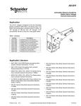
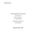
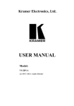
AV-607-1 AV-609-1 SmartX Actuator Linkages for 1-1/2” to 6” Globe Valves General Instructions Application AV-607-1 and AV-609-11 linkages are designed to connect single or dual Schneider Electric spring return and nonspring return SmartX Actuators to 1-1/2” to 6” VB-9xxx and 2-1/2” to 6” VB-8xx3 globe valves. Features • Allows mounting of single or dual Schneider Electric SmartX Actuators • AV-607-1 is compatible with Schneider Electric (Siebe, Barber-Colman, INVENSYS) 2-1/2” to 5” VB-8xx3, 1-1/2” to 4” VB-931x, and discontinued 1-1/2” to 4” VB-92xx valves and Schneider Electric SmartX actuators2 • AV-609-1 is compatible with Schneider Electric (Siebe, Barber-Colman, INVENSYS) 6” VB-8xx3, 5” and 6” VB931x, and discontinued 5” and 6” VB-92xx valves and Schneider Electric SmartX Actuators2 AV-607-1 • Maintenance-free construction • Corrosion protected heavy-duty steel rack and pinion construction and metal housing • Precision rack self aligns with the valve stem AV-609-1 1 AV-607-1 and AV-609-1 replace AV-607 and AV-609 respectively 2 Check the appropriate valve selection guide for close-offs for your application, Schneider Electric F-27479-3 Note: Do not install a 300 lb-in MX41-634-x actuator on the AV-607-1 linkage as equipment damage may occur. 1-888-444-1311 Product Support Services www.schneider-electric.com April 2014 2 Applicable Literature • EN-205 Water System Guidelines, F-26080 • AV-608 Linkage Adapter Kit General Instructions, F-27253 • MA40-704x, MA4x-707x, MA4x-715x Schneider Electric SmartX Spring Return Two-Position Actuators General Instructions, F-26642 • • • • • • • MA40-717x Schneider Electric SmartX Series Spring Return Two-Position Actuators General Instructions, F-26742 MF4x-7xx3 Schneider Electric SmartX Series Spring Return Floating Actuator General Instructions, F-26644 MF40-7173 Schneider Electric SmartX Series Spring Return Floating Actuator General Instructions, F-26749 MF41-6153,/MS41-6153 Series Non-Spring Return Rotary Electronic Damper Actuator General Instructions, F-27215 MS4x-7xx3 Schneider Electric SmartX Series Spring Return Proportional Actuator General Instructions, F-26645 MS40-717x Schneider Electric SmartX Series Spring Return Proportional Actuator General Instructions, F-26748 Mx41-6xxx-220/-230 and MX4x-7xxx-220/-230 Actuator/Linkage Assemblies for 2-1/2” to 6” Globe Valves General Instructions, F-27160 • Vx-7000 Series and Vx-9000 Series Mx4x-6xxx and Mx4x-7xxx Series Linked Globe Valve Assemblies with Schneider Electric SmartX Actuators Selection Guide, F-26752 • VB-8xx3 Series Balanced Plug Valve Selection Guide, F-27199 Accessories • PKG-1171 Replacement Hardware kit (to replace lost hardware; see Figure‑1) Clamps (4) AV-609-1 Stabilizer Factory assembled to linkage Stem Nuts (2) Clamp Blocks (4)* NYBA-206 Anti-Rotation Stud for MX41-6153 (2) For AV-607-1 Only AV-607-1 Stabilizer Factory assembled to linkage Anti-Rotation Spacer Factory assembled to linkage Spacer NYBA-148 Anti-Rotation Stud for Mx4x40-717x and NYBA-161 Mx41-6343 (2) Anti-Rotation Stud for Mx4x-707x and MX4x-715x (2) Factory assembled to linkage * Clamp blocks are only required for the MX41-634x and Mx40-717x actuators. Figure-1 Replacement Hardware Inspection Inspect package for damage. If damaged, notify carrier immediately. If undamaged, open the package and inspect for obvious damage. Return damaged products. Inspect the hardware package included with the linkage to make sure all required clamps (4), clamp blocks (4), stem lock nuts (2), and anti-rotation studs (six, two factory assembled to linkage) are included. See Figure-1. Not all parts will be needed for every installation. Requirements • Training: Installer must be a qualified, experienced technician. • Tools (not provided): – – – – – – – – – Appropriate wrenches for anti-rotation studs, stem extensions, packing nuts, and bracket nuts 10 mm socket wrench (for shaft clamp nuts on Mx40-717x, Mx41-707x, Mx41-715x) 1/2” nut driver and 1/2” open end wrench (for all except Mx41‑634x, Mx40‑717x) Measuring scale graduated in 1/32” increments Torque wrench, range to include 90 to 120 lb-in. (7.5 to 10 lb-ft, 10 to 14 N-m) Pipe wrenches, two 11/16” open-end wrench for jam nuts, two Vise grip or pliers Appropriate power supply (see the applicable actuator General Instructions sheet for power requirements) Warning: Electrical shock hazard! Contact with live circuits can result in severe injury or death. • Disconnect the power supply (line power) at the breaker or fuse before and during installation to prevent electric shock and equipment damage. • Make all connections in accordance with the wiring diagram and in accordance with national and local electrical codes. Use copper conductors only. Failure to observe these warnings can result in severe injury or death and can damage the equipment. Schneider Electric F-27479-3 1-888-444-1311 Product Support Services www.schneider-electric.com April 2014 3 General Installation Schneider Electric globe valve rack and pinion linkages are provided as complete assemblies. The following pages contain instructions for installing the AV‑607-1 and AV‑609-1 linkages. Either a single actuator or dual actuators may be installed using these instructions. Note: When installing dual actuators: • Both actuators must be the same model. • Actuators must be mounted and adjusted so as to rotate and spring return (if applicable) in the same direction. Refer to the mounting instructions and Table‑ through Table-x. • Refer to the applicable actuator literature for actuator wiring information. • Only use the actuator and linkage combinations that are shown on Table 1. Linkage or valve damage could result if a in correct combination is applied. • Do not attempt to use the actuator manual override feature with two actuators clamped to the same shaft. Damage and improper operation can occur. Using manual override to set individual actuator preload before installation on the linkage is permissable. Mounting Actuator and Linkage to Valve Body Process Overview This mounting procedure consists of two sections: • Section A. Mounting Linkage to Valve – A1. Select and install anti-rotation studs. – A2. VB-9xxx and VB-8xx3 (2-way and 3-way) valves and appropriate actuator types, follow the instructions in this section to assemble the linkage to the valve • Section B. Actuator Mounting and Setup In this section, choose the subsection that is appropriate for the specific actuator type and valve type, to mount the actuator and adjust the linkage: – B1. Spring Return Actuators with Manual Override 2-Way Valves and 3-Way Valves (Normal Position — Valve Stem Up) – B2. Spring Return Actuators with Manual Override 2-Way Valves and 3-Way Valves (Normal Position — Valve Stem Down) – B3. Non-Spring Return Actuator with Manual Override VB-8213 and VB-921x 2-Way Valves (Valve Stem Up, Open) VB8223 and VB-922x 2-Way Valves (Valve Stem Up, Closed) VB-8303 and VB-931x 3-Way Valves (Valve Stem Up, Port A Closed) – B4. Spring Return Actuators without Manual Override VB-8223, VB-922x 2-Way Valves (Normal Position — Valve Stem Up, Closed) VB-8303, VB-931x 3-Way Valves (Normal Position — Valve Stem Up, Port A Closed) – B5. Spring-Return Actuators without Manual Override VB-8213, VB-921x 2-Way Valves (Normal Position — Valve Stem Down, Closed) VB-8303, VB-931x 3-Way Valves (Normal Position — Valve Stem Down, Port B Closed) The linkage is assembled to the valve according to Section A. Refer to Table‑1, below, to determine the remainder of the assembly path for a specific actuator and valve. Table-1 Procedure for Mounting Actuator and Linkage to Valve Body. Actuator Type Valve Type Section B Subsection B1 Subsection B2 Subsection B3 Spring Return Actuators with Manual Override Mx41-707x Mx41-715x 2-Way and 3-Way, Normal Position Valve Stem Up Non-Spring Return Actuators with Manual Override Mx41-6153 Mx41-634x 2-Way and 3-Way, Normal Position Valve Stem Up X 2-Way and 3-Way, Normal Position Valve Stem Down X Spring Return Actuators without Manual Override Mx40-717x 2-Way and 3-Way, Normal Position Valve Stem Up 2-Way and 3-Way, Normal Position Valve Stem Down F-27479-3 Subsection B5 X X X 2-Way and 3-Way, Normal Position Valve Stem Downa Schneider Electric Subsection B4 X 1-888-444-1311 Product Support Services www.schneider-electric.com April 2014 4 Section A. Mounting Linkage to Valve A1. Select and Install Anti-Rotation Studs. Based on the actuator(s) being used, select the appropriate anti-rotation studs using Figure‑. Two NYBA-161 anti-rotation studs (for Mx4x-707x and Mx4x-715x actuators) are shipped factory assembled to each side of the linkage. If NYBA-148 or NYBA-206 are required, remove the two factory-installed anti-rotation studs one at a time and replace them with the required studs. Hand tighten the stud in the linkage frame slot and slide down to provide clearance for actuator installation (see Figure-2 below). NYBA-161 for Mx4x-707x, MX4x-715x (Factory assembled to linkage) NYBA-148 for Mx40-717x, Mx41-6343 AV-601-1 Only NYBA-206 for Mx41-6153 AV-607-1 Only Anti-Rotation Studs (2) (one each side) Figure-2 Anti-Rotation Studs A2. Mounting Linkage to Valve — VB-9xxx, VB-8xxx, and Appropriate1 Actuator Models 1. Assemble the linkage to the valve, according to Figure‑3. 2. Continue the assembly process according to the following section, “Section B. Actuator Mounting and Setup.” 1 See Table‑1 on page 3 1 2 Thread the spanner nut onto the bonnet, and then place the spacer (provided with the AV-607-1 and AV-609-1) on top of the spanner nut. Thread the two jam nuts (provided with the AV-607-1 and AV-609-1) onto the valve stem. Adjust the spanner nut and jam nuts to the height shown. 3 Tighten the two jam nuts against each other, using two 11/16" open-end wrenches. Valve Stem 3 threads visible, minimum 2-1/2" to 6" VB-8213 2-Way VB-921x 2-Way, Stem Up Open VB-8223 2-Way, Stem Up Closed & VB-8303 3-Way Jam Nuts (2) 2-1/2" to 5" for VB-8000 Series 2-1/2" to 4” for VB-9000 Series Spacer 1 thread visible minimum 1-11/16" ± 1/32" (with stem down) Spanner Nut 6" Valves for VB-8000 Series 5” and 6” for VB-9000 Series 2-19/32" ± 1/32" (with stem up) 3-19/32" ± 1/32" (with stem up) Typical Valve Body (2-Way shown) 7 4 Rotate the pinion shaft CW to fully lower the rack, and then position the linkage over the valve stem. Orient the linkage on the valve as desired by rotating the linkage up to one turn 8 5 9 6 Tighten the spanner nut against the spacer. Turn the entire linkage to partially thread the rack onto the valve stem. Thread the entire linkage onto the bonnet until it contacts the spacer. Tighten the jam nuts against the rack, using an 11/16" open-end wrench on the lower jam nut. Note: The valve stem will rotate with the jam nuts. 1 1 To allow easier rotation of the jam nuts and valve stem, unseat the valve stem by rotating the pinion shaft slightly CW or CCW. Figure-3 Assembling Linkage to Valve Schneider Electric F-27479-3 1-888-444-1311 Product Support Services www.schneider-electric.com April 2014 5 Section B. Actuator Mounting and Setup To mount the actuator and set up the assembly, refer to the subsection that applies to the specific actuator type and valve type. B1. Spring Return Actuators with Manual Override 2-Way Valves and 3-Way Valves (Normal Position — Valve Stem Up) Mx41-707x (VB-9xxx only with AV-607-1) and Mx41-715x (AV-607-1 and AV-609-1) a. Install the actuator (or actuators if using dual actuators) onto the linkage and valve, and set up the assembly, according to Table‑3 on page 10 or Table‑3 on page 11 Note: If using dual actuators, make sure both rotate and spring return in the same direction. Do not use manual override on installed actuators if using dual actuators. See “General Installation” on page 3. 1 Normal Position - Valve Stem Up 5 VB-8213 & VB-921x 2-Way, Stem Up Open 1 Set the actuator preload to an indicator reading of 80° (i.e. 10° from the end of stroke). Make sure the actuator is in full contact with the plastic stand-offs on the linkage. 6 VB-8223 & VB-922x 2-Way, Stem Up Closed VB-8303 & VB-931x 3-Way, Port A Closed Set the actuator preload to an indicator reading 1 of 5°. Remove anti-rotation stud if assembled on 80° linkage. Note: The manual override disengages when the actuator is powered. The manual override may also be manually disengaged using the supplied hex wrench. To do this, turn, then release, the hex wrench approximately 5° CW, to "jog" the mechanism and release the manual override preset. Note that 1 to 1-1/2 turns of the manual override crank is approximately 10°. 5° 2 Slide the actuator, "L" side facing out, onto the linkage's pinion shaft. 3 Align the actuator with the linkage. 4 Slide anti-rotation stud(s) NYBA-161 half way into the slot on the bottom of the actuator, and then tighten the the anti-rotation stud. Ensure the valve is in the closed position (see Table-6; port A closed for 3-way). Use a 10 mm wrench or socket to tighten the two nuts equally on the shaft clamp, 8 to 10 lb-ft (11 to 14 N-m). L R L K LOC R K LOC 7 NYBA-161 Anti-Rotation Stud 1 L Refer to the applicable table in "Setting Actuator/Valve Action" and, using a screwdriver, turn the L/R selector to choose "direct acting" or "reverse acting." 8 Wire the actuator in accordance with the job wiring diagrams and the wiring information contained in the applicable actuator General Instructions (see "Applicable Literature"). 9 Optional: Affix the Open and Closed labels to the angle of rotation indicator, in positions to match the actual valve stroke. The Mx41-707x and Mx41-715x actuators feature a manual override mechanism that may be used to reposition the actuator’s output shaft. Both actuators have 95° of stroke (from indicator reading -5° to 90°). Caution: Do not use manual override if using dual actuators! CLOSED OPEN Figure-4 Mounting Mx41-707x or M41-715x and Setting Up Actuator/Linkage/Valve b. Refer to the appropriate actuator General Instructions sheet for actuator wiring and application information (see “Applicable Literature” on page 2). For valve body installation and application information, refer to the appropriate valve body General Instructions sheet. c. Power the actuator(s) and check the system’s operation for heating or cooling output, in response to the control signal. See “Setting Actuator/Valve Action” on page 10. Schneider Electric F-27479-3 1-888-444-1311 Product Support Services www.schneider-electric.com April 2014 B2. Spring Return Actuators with Manual Override 2-Way Valves and 3-Way Valves (Normal Position — Valve Stem Down) 6 Mx41-707x (VB-9xxx only with AV-607-1) and Mx41-715x (AV-607-1 and AV-609-1) a. Install the actuator (or actuators if using dual actuators) onto the linkage and valve, and set up the assembly, according to Table‑2 on page 10 or Table‑3 on page 11. Note: If using dual actuators, make sure both rotate and spring return in the same direction. Do not use manual override on installed actuators if using dual actuators. See “General Installation” on page 3. Normal Position - Valve Stem Down 1 5 VB-8213 & VB-921x 2-Way, Stem Up Open Set the actuator preload to an indicator reading1 of 5°. Make sure the actuator is in full contact with the plastic stand-offs on the linkage. 6 VB-8223 & VB-922x 2-Way, Stem Up Closed VB-8303 & VB-931x 3-Way, Port B Closed Set the actuator preload to an indicator reading 1 of 80° (i.e. 10° from the end of stroke). Ensure the valve is in the closed position (see Table-6; port A closed for 3-way). Use a 10 mm wrench or socket to tighten the two nuts equally on the shaft clamp, 8 to 10 lb-ft (11 to 14 N-m). Note: The manual override disengages when the actuator is powered. The manual override may also be manually disengaged using the supplied hex wrench. To do this, turn, then release, the hex wrench approximately 5° CW, to "jog" the mechanism and release the manual override preset. Note that 1 to 1-1/2 turns of the manual override crank is approximately 10°. 80° R 2 Slide the actuator, "R" side facing out, onto the linkage's pinion shaft. Relocate the actuator clamp to the outboard side if necessary. L 5° R K LOC R 3 4 Align the actuator with the linkage. K LOC Slide anti-rotation stud(s) NYBA-161 half way into the slot on the bottom of the actuator, and then tighten the nut on the anti-rotation stud. 7 Refer to the applicable table in "Setting Actuator/Valve Action" and, using a screwdriver, turn the L/R selector to choose "direct acting" or "reverse acting." 8 Wire the actuator in accordance with the job wiring diagrams and the wiring information contained in the applicable actuator General Instructions (see "Applicable Literature"). 9 Optional: Affix the Open and Closed labels to the angle of rotation indicator, in positions to match the actual valve stroke. NYBA-161 Anti-Rotation Stud CLOSED 1 L The Mx41-707x and Mx41-715x actuators feature a manual override mechanism that may be used to reposition the actuator’s output shaft. Both actuators have 95° of stroke (from indicator reading -5° to 90°). OPEN Caution: Do not use manual override if using dual actuators! Figure-5 Mounting Mx41-707x or M41-715x and Setting Up Actuator/Linkage/Valve b. Refer to the appropriate actuator General Instructions sheet for actuator wiring and application information (see “Applicable Literature” on page 2). For valve body installation and application information, refer to the appropriate valve body General Instructions sheet. c. Power the actuator(s) and check the system’s operation for heating or cooling output, in response to the control signal. See “Setting Actuator/Valve Action” on page 10. Schneider Electric F-27479-3 1-888-444-1311 Product Support Services www.schneider-electric.com April 2014 7 B3. Non-Spring Return Actuator with Manual Override VB-8213 and VB-921x 2-Way Valves (Valve Stem Up, Open) VB-8223 and VB-922x 2-Way Valves (Valve Stem Up, Closed) VB-8303 and VB-931x 3-Way Valves (Valve Stem Up, Port A Closed) Mx41-6153 Series (VB-9xxx only) Actuator with AV-607-1 Linkage, Mx41-634x Actuator with AV‑609-1 Linkage Only a. Install the actuator (or actuators if using dual Mx41-6153 actuators) onto the linkage and valve, and set up the assembly, according to Figure‑7 on page 8 and Table‑4 on page 11 or Table‑5 on page 12. Note: If using dual actuators, make sure both rotate in the same direction. Do not use manual override on installed actuators if using dual actuators. See “General Installation” on page 3. Shaft Clamp Nut 1 Rotate the linkage's pinion shaft to the valve closed position: • Stem Up Closed VB-922x Series and VB-931x Series Valves Rotate the pinion shaft CCW to retract the linkage rack to the up position. Stem Up Closed (shown) Manual Override Button Slide the actuator onto the linkage's pinion shaft. Mx41-6343 Series - Install with the "L" side facing out. 4 Align the actuator with the linkage. Slide the anti-rotation stud half way into the slot on the bottom of the actuator, and then tighten the nut on the anti-rotation stud. Mx41-6343 Series - Position the output shaft as shown: Mx41-6153 Series a. Press and hold down the manual override button. b. Position the actuator output shaft, 10° stem up open or 10° stem up closed (note that each increment is 5°). c. When finished, release the manual override button. NYBA-148 Anti-Rotation Stud for Mx41-6343 10° 1 Position the actuator's output shaft as follows: Mx41-6343 Series a. Using the supplied hex wrench, position the actuator's output shaft at 1 10° stem up open or 10° stem up closed (note that each increment is 5°) Mx41-6153 Series 3 OPEN 5 • Stem Up Open VB-921x Series Rotate the pinion shaft CW to Stem Up extend the linkage rack to the down Open position. 2 CLOSED Optional: Affix the Open and Closed labels to the indicator in the appropriate positions. Stem Up Open 6 NYBA-206 Anti-Rotation Stud for Mx41-6153 Verify that the actuator is in full contact with the plastic stand-offs on the linkage. Once the valve is in the closed position, proceed as follows: Mx41-6153 Series Using a 10 mm wrench or socket, tighten the shaft clamp nut 7.5 to 9 lb-ft (10 to 12 N-m). Do not over-tighten. Stem Up Closed 10° L Mx41-6343 Series Using a 1/2" wrench or socket, tighten the shaft Figure-6 Mounting Mx41-6153 Series or Mx41-634x Series Actuator and Setting Up Actuator/Linkage/Valve b. Refer to the appropriate actuator General Instructions sheet for actuator wiring and application information (see “Applicable Literature” on page 2). For valve body installation and application information, refer to the appropriate valve body General Instructions sheet. c. Power the actuator(s) and check the system’s operation for heating or cooling output, in response to the control signal. See “Setting Actuator/Valve Action” on page 10. Schneider Electric F-27479-3 1-888-444-1311 Product Support Services www.schneider-electric.com April 2014 8 B4. Spring Return Actuators without Manual Override VB-8223, VB-922x 2-Way Valves (Normal Position — Valve Stem Up, Closed) VB-8303, VB-931x 3-Way Valves (Normal Position — Valve Stem Up, Port A Closed) Mx40-717x (AV-607-1 and AV-609-1) a. Install the actuator (or actuators if using dual actuators) onto the linkage and valve, and set up the assembly, according to Table‑3 on page 11. Use the two clamps supplied with the linkage. Note: If using dual actuators, make sure both rotate and spring return in the same direction. Clamp blocks (one for each clamp; see steps 2 and 5) 1 Rotate the linkage's pinion shaft CCW, to retract the rack (stem up). 2 5 L Slide the actuator, "L" side facing out, onto the linkage's pinion shaft. Make sure clamp blocks are inserted between pinion shaft and each clamp. With clamp blocks in place, hold the actuator at the 10° position. Use a 1/2" wrench or socket to tighten the two nuts equally on each shaft clamp, 4 to 6 lb-ft (5 to 8 N-m). 1-5/8" Open-End Wrench 1-3/8" TOOL-3 7 3 1 4 1 2 1-5/8" Align the actuator with the linkage, then rotate it 10° CW. Note that 1-3/8" movement at the anti-rotation slot (measured at the slot's centerline) is sufficiently equal to 2 2 Make sure the actuator is in full contact with the plastic stand-offs on the linkage, and that the valve is in the full up position. Tip: • Anti-Rotation Stud for Mx40-717x Mx40-717x actuators are shipped at the zero position, without preload. 3 NYBA-148 100 Tip: A 1-5/8" open-end wrench (TOOL-37) can be used to measure the amount of rotation (measured between opposite sides of the slot). 6 Apply power to rotate the actuator body CCW into alignment with the linkage, and then slide the anti-rotation stud (NYBA-148) halfway into the slot on the bottom of the actuator. Tighten the 3 nut on the anti-rotation stud. ! Caution: Take care not to pinch your fingers or hand between the actuator and the linkage, when powering the actuator into alignment. MA40-717x Two-Position - When power is applied to L1, L2 (Red / Black 24V) (White / Black 120v) (Lt Blue / Brown 240v) the actuator will travel CW (As viewed from the L side). Caution: When setting the valve preload, power must be used to position the actuator. Do not manually force the actuator into the mounting position. If forced, damage to the pinion shaft or improper close-off may occur. • MF40-7173 Floating Control - The Yellow/Black lead drives the actuator CCW and the Blue lead drives the actuator CW (as viewed from the "L" side). The Red lead is 24 hot and the Black is 24 Ground. Making the Red lead to the Blue lead will drive the actuator CW. • MS40-717x Proportional Control - Apply 10Vdc to the Gray (COM) and Yellow/Black (+) Leads, and then apply power to( L1 and L2) (Brown / Light Blue 240v) (Black / White 120v) or (Red / Black 24v) to drive the actuator CW (As viewed from the L Side). CLOSED 7 OPEN Optional: Affix the Open and Closed labels to the indicator, in positions to match the actual valve stroke. Figure-7 Mounting Mx40-717x and Setting Up Actuator/Linkage/Valve b. Refer to the appropriate actuator General Instructions sheet for actuator wiring and application information (see “Applicable Literature” on page 2). For valve body installation and application information, refer to the appropriate valve body General Instructions sheet. c. Power the actuator(s) and check the system’s operation for heating or cooling output, in response to the control signal. See “Setting Actuator/Valve Action” on page 10. Schneider Electric F-27479-3 1-888-444-1311 Product Support Services www.schneider-electric.com April 2014 9 B5. Spring-Return Actuators without Manual Override VB-8213, VB-921x 2-Way Valves (Normal Position — Valve Stem Down, Closed) VB-8303, VB-931x 3-Way Valves (Normal Position — Valve Stem Down, Port B Closed) Mx40-717x (AV-607-1 and AV-609-1) a. Install the actuator (or actuators if using dual actuators) onto the linkage and valve, and set up the assembly, according to and Table‑3 on page 11. Use the two clamps supplied with the linkage. Note: If using dual actuators, make sure both rotate and spring return in the same direction. Clamp block (one for each 5 With clamp blocks in place, hold the actuator at the 10° position. Use a 1/2" wrench or socket to tighten the two nuts equally on each shaft clamp, 4 to 6 lb-ft (5 to 8 N-m). clamp; see steps 2 and 5) R 1 Rotate the linkage's pinion shaft CW, to extend the rack (stem down). 2 Slide the actuator, "R" side facing out, onto the linkage's pinion shaft. Make sure clamp blocks are inserted between pinion shaft and each clamp. 1-3/8" 7 TOOL-3 1-5/8" Open-End 3 1 4 1 3 Wrench Align the actuator with the linkage, then rotate it 10° CCW. Note that 1-3/8" movement at the anti-rotation slot (measured at the slot's centerline) is sufficiently equal to 10°. 1-5/8" 2 2 2 Make sure the actuator is in full contact with the plastic stand-offs on the linkage, and that the valve is in the full down NYBA-148 Anti-Rotation Stud for 10° 6 Tip: • MA40-717x Two-Position - When power is applied to L1, L2 (Red / Black 24V) (White / Black 120v) (Lt Blue / Brown 240v) the actuator will travel CWW (As viewed from the "R" side). ! Apply power to rotate actuator body CW into alignment with the linkage, and then slide the anti-rotation stud (NYBA-148) halfway into the slot on the bottom of the actuator. Tighten the nut on the 3 anti-rotation stud. Caution: Take care not to pinch your fingers or hand between the actuator and the linkage, when powering the actuator into alignment. Caution: When setting the valve preload, power must be used to position the actuator. Do not manually force the actuator into the mounting position. If forced, damage to the pinion shaft or improper close-off may occur. • MF40-717x Floating Control - the Yellow/Black lead drives the actuator CW and the Blue lead drives the actuator CCW (as viewed from the "R" side). The Red lead is 24 hot and the Black is 24 Ground. Making the Red lead to the Blue lead will drive the actuator CCW. MS40-717x Proportional Control - Apply 10Vdc to the Gray (COM) and Yellow/Black (+) Leads, and then apply power to L1 and L2 (Brown / Light Blue 240v) (Black/ White 120v) or (Red / Black 24v) to drive the actuator full CCW (As viewed from the "R" Side). Tip: A 1-5/8" open-end wrench (TOOL-37) can be used to measure the amount of rotation (measured between opposite sides of the slot). Mx40-717x Mx40-717x actuators are shipped at the zero position, without preload. • 2 CLOSED 7 OPEN Optional: Affix the Open and Closed labels to the indicator, in positions to match the actual valve stroke. Figure-8 Mounting Mx40-717x and Setting Up Actuator/Linkage/Valve b. Refer to the appropriate actuator General Instructions sheet for actuator wiring and application information (see “Applicable Literature” on page 2). For valve body installation and application information, refer to the appropriate valve body General Instructions sheet. c. Power the actuator(s) and check the system’s operation for heating or cooling output, in response to the control signal. See “Setting Actuator/Valve Action” on page 10. Schneider Electric F-27479-3 1-888-444-1311 Product Support Services www.schneider-electric.com April 2014 10 Setting Actuator/Valve Action Set the actuator/valve action according to Table-2, Table-3, Table-4, or Table-6. These tables may also be used to check the action of the completed actuator/linkage/valve assembly. Table-2 Mx41-707x Mx41-715x Series Spring Return Actuators. Primarya Secondaryb Actuator Actuator Valve Part Number Facing Switch Facing Switch Side Setting Side Setting Control Signal Increase Primary Actuator Rotationc Secondary Primary Secondary Valve Stem Actuator Valve Action Actuator Actuator Moves Rotationc Rotationc Rotationc L L R R CW CCW Down Closes CCW CW VB-921x L R R L CCW CW Up Opens CCW CW VB-8213 R L L R CW CCW Down Closes CW CCW R R L L CCW CW Up Opens CW CCW L L R R CW CCW Down Opens CCW CW L R R L CCW CW Up Closes CCW CW VB-922x VB-8223 R L L R CW CCW Down Opens CW CCW R R L L CCW CW Up Closes CW CCW L L R R CW CCW Down “A” Opens “B” Closes CCW CW L R R L CCW CW Up “A” Closes “B” Opens CCW CW R L L R CW CCW Down “A” Opens “B” Closes CW CCW R R L L CCW CW Up “A” Closes “B” Opens CW CCW L L R R CW CCW Down “A” Opens “B” Closes CCW CW L R R L CCW CW Up “A” Closes “B” Opens CCW CW R L L R CW CCW Down “A” Opens “B” Closes CW CCW R R L L CCW CW Up “A” Closes “B” Opens CW CCW VB-931x VB-8303 a Primary actuator is mounted on side of linkage with rack not visible b Secondary actuator is mounted on side of linkage with rack visible. c Spring Return Valve Normal Position Open (Stem Up) Closed (Stem Down) Closed (Stem Up) Open (Stem Down) “A” Closed “B” Open (Stem Up) “A” Open “B” Closed (Stem Down) “A” Closed “B” Open (Stem Up) “A” Open “B” Closed (Stem Down) As viewed facing actuator. Schneider Electric F-27479-3 1-888-444-1311 Product Support Services www.schneider-electric.com April 2014 11 Table- 3 MA40-717x Spring Return Actuators. Valve Part Number VB-921x VB-8213 VB-922x VB-8223 Primarya Actuator Secondaryb Actuator Facing Side Facing Side Primary Actuator Rotationc Secondary Actuator Rotationc Valve Stem Moves Valve Action Primary Actuator Rotationc Secondary Actuator Rotationc Valve Normal Position L R CW CCW Down Closes CCW CW Open (Stem Up) R L CCW CW Up Opens CW CCW Closed (Stem Down) L R CW CCW Down Opens CCW CW Closed (Stem Up) R L CCW CW Up Closes CW CCW Open (Stem Down) L R CW CCW Down “A” Opens “B” Closes CCW CW “B” Open, “A” Closed (Stem Up) R L CCW CW Up “A” Opens “B” Closes CW CCW “A” Open, “B” Closed (Stem Down) L R CW CCW Down “A” Opens “B” Closes CCW CW “B” Open, “A” Closed (Stem Up) R L CCW CW Up “A” Closes “B” Opens CW CCW “A” Open, “B” Closed (Stem Down) Control Signal Increase VB-931x VB-8303 a Primary actuator is mounted on side of linkage with rack not visible b Secondary actuator is mounted on side of linkage with rack visible. c Spring Return As viewed facing actuator. Table-4 MF41-6153 Floating, MS41-6153 Proportional Non-Spring Return Actuators (AV-607-1 Only) Control Signal Increase Valve Part Number VB-921x VB-8213 VB-922x VB-8223 Primarya Actuator Rotationb CWd Secondaryc Actuator Rotationb CCWe Valve Stem Moves Down CCWe CWd Up Opens CWd CCWe Down Opens CCWe CWd Up Closes CW CCWe Down “A” Opens, “B” Closes CCWe CWd Up “A” Closes, “A” Opens CW CCWe Down “A” Opens, “B” Closes CWd Up “A” Closes, “A” Opens d VB-931x VB-8303 d CCWe a Primary actuator is mounted on side of linkage with rack not visible b Secondary actuator is mounted on side of linkage with rack visible. Valve Action Closes As viewed facing actuator. MF models: control signal applied to Wire 6 (Y1). c d MF models: control signal applied to Wire 6 (Y1). MS models: DIP switch set to “CW”. e MF models: control signal applied to Witre 7 (Y2). MS models: DIP switch set to “CCW”. Schneider Electric F-27479-3 1-888-444-1311 Product Support Services www.schneider-electric.com April 2014 Table-5 Mx41-6343 Floating and Mx41-634x Proportional Non-Spring Return Actuator (AV-609-1 Only) Valve Part Number VB-921x VB-8213 VB-922x VB-8223 VB-931x VB-8303 Primarya Actuator Secondaryb Actuator Facing Side Facing Side Primary Actuator Rotationc Secondary Actuator Rotationc Valve Stem Moves Valve Action L R CW CCW Down Closes R L CCW CW Up Opens L R CW CCW Down Opens R L CCW CW Up Closes L R CW CCW Down “A” Opens, “B” Close R L CCW CW Up “A” Closes, “B” Opens L R CW CCW Down “A” Opens, “B” Closes R L CCW CW Up “A” Closes, “B” Opens Control Signal Increase a Primary actuator is mounted on side of linkage with rack not visible b Secondary actuator is mounted on side of linkage with rack visible. As viewed facing actuator. c Valve Body Action Table-6 Valve Body Action Valve Body Part Number VB-8213 Two-way stem up open VB-8223 Two-way stem up closed VB-8303 Three-way diverting / mixinga VB-921x Two-way stem up open VB-922x Two-way stem up closed VB-931x Three-way mixinga Valve Action Stem Up Stem Down Open Closed Closed Open Port A Closed Port B Opena Port A Open Port B Closeda Open Closed Closed Open Port A Closed Port B Opena Port A Open Port B Closeda AB port is the common port on 3-way valves © 2014 Schneider Electric. All rights reserved. a Description Schneider Electric F-27479-3 1-888-444-1311 Product Support Services www.schneider-electric.com April 2014