1
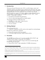
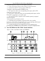
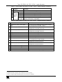
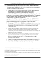
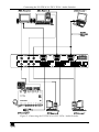
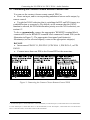
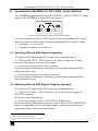
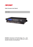
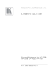
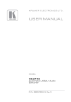
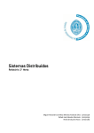
Kramer Electronics, Ltd.
USER MANUAL
Model:
VS-2DVA
2x1 DVI / XGA / Audio Switcher
Contents
Contents
1
2
3
4
5
5.1
6
6.1
6.2
7
Introduction
Getting Started
Overview
Your VS-2DVA 2x1 DVI / XGA / Audio Switcher
Connecting the VS-2DVA 2x1 DVI / XGA / Audio Switcher
Connecting the Contact Closure Remote Control PINS
Operating the VS-2DVA 2x1 DVI / XGA / Audio Switcher
Switching DVI and XGA Signals Separately
Switching DVI and XGA Signals Together (Ganged)
Technical Specifications
1
1
1
2
4
6
7
7
7
8
Figures
Figure 1: VS-2DVA 2x1 DVI / XGA / Audio Switcher
Figure 2: Connecting the VS-2DVA 2x1 DVI / XGA / Audio Switcher
Figure 3: Connecting the Contact Closure Remote Control PINS
Figure 4: Initial Status of the SELECTOR Buttons
2
5
6
7
Tables
Table 1: Front Panel VS-2DVA 2x1 DVI / XGA / Audio Switcher Features
Table 2: Rear Panel VS-2DVA 2x1 DVI / XGA / Audio Switcher Features
Table 3: Technical Specifications of the VS-2DVA 2x1 DVI / XGA / Audio Switcher
3
3
8
i
Introduction
1
Introduction
Welcome to Kramer Electronics (since 1981): a world of unique, creative and
affordable solutions to the infinite range of problems that confront the video, audio
and presentation professional on a daily basis. In recent years, we have redesigned
and upgraded most of our line, making the best even better! Our 350-plus
different models now appear in 8 Groups1, which are clearly defined by function.
Congratulations on purchasing your VS-2DVA 2x1 DVI / XGA2 / Audio
Switcher. This product is ideal for:
Presentation and multimedia applications
Preview and monitoring graphics and audio signals
The package includes the following items:
VS-2DVA 2x1 DVI / XGA2 / Audio Switcher
Power adapter (12V DC Input)
This user manual3
2
Getting Started
We recommend that you:
Unpack the equipment carefully and save the original box and packaging
materials for possible future shipment
Review the contents of this user manual
Use Kramer high performance high resolution cables4
3
Overview
The VS-2DVA is an all-in-one 2x1 switcher for DVI, XGA/UXGA2, and
unbalanced audio signals. In particular, the VS-2DVA:
Equalizes and reclocks the DVI input, effectively reconstructing and
retransmitting the DVI signal
Has an XGA/UXGA1 video bandwidth of 350MHz, that ensures
1 GROUP 1: Distribution Amplifiers; GROUP 2: Video and Audio Switchers, Matrix Switchers and Controllers; GROUP 3:
Video, Audio, VGA/XGA Processors; GROUP 4: Interfaces and Sync Processors; GROUP 5: Twisted Pair Interfaces;
GROUP 6: Accessories and Rack Adapters; GROUP 7: Scan Converters and Scalers; and GROUP 8: Cables and Connectors
2 Handles all known computer video resolutions (VGA to UXGA)
3 Download up-to-date Kramer user manuals from the Internet at this URL: http://www.kramerelectronics.com/manuals.html
4 The complete list of Kramer cables is on our Web site at http://www.kramerelectronics.com (click “Cables and Connectors”
in the Products section)
1
Your VS-2DVA 2x1 DVI / XGA / Audio Switcher
transparent operation is achieved at the highest resolutions
Comes with contact closure remote control for forced operation
Is housed in a half 19" rack size and is 12VDC fed
In addition, with the high quality VS-2DVA, both:
DVI inputs have their own corresponding audio inputs, and the DVI
output has its own audio output
XGA/UXGA1 inputs have their own corresponding audio inputs, and the
XGA/UXGA output has its own audio output
DVI and XGA/UXGA1 signals can be switched separately or ganged
(switched together)
Achieving the best performance means:
Connecting only good quality connection cables, thus avoiding
interference, deterioration in signal quality due to poor matching, and elevated
noise levels (often associated with low quality cables)
Avoiding interference from neighboring electrical appliances and
positioning your VS-2DVA away from moisture, excessive sunlight and dust
4
Your VS-2DVA 2x1 DVI / XGA / Audio Switcher
Figure 1, Table 1 and Table 2 define the VS-2DVA:
Figure 1: VS-2DVA 2x1 DVI / XGA / Audio Switcher
1 Handles all known computer video resolutions (VGA to UXGA)
2
KRAMER: SIMPLE CREATIVE TECHNOLOGY
Your VS-2DVA 2x1 DVI / XGA / Audio Switcher
Table 1: Front Panel VS-2DVA 2x1 DVI / XGA1 / Audio Switcher Features
Feature
Function
POWER Switch
DVI 2
DVI 1
1
XGA 1
1
XGA 2
GANG
1
DVI+XGA
Illuminated switch for turning the unit ON or OFF
Press to select the DVI source at input 2
Press to select the DVI source at input 1
1
Press to select the XGA source at input 1
1
Press to select the XGA source at input 2
1
Press to toggle between switching the DVI and the XGA
signals in one action or separately
SELECTOR
Buttons
#
1
2
3
4
5
6
Table 2: Rear Panel VS-2DVA 2x1 DVI / XGA1 / Audio Switcher Features
#
1
2
3
4
5
6
7
8
9
10
11
12
13
14
Feature
Function
1
AUDIO OUT (XGA ) 3.5mm Mini
Connects to the unbalanced stereo audio acceptor
1
Jack
that corresponds to the XGA output
1
AUDIO IN 2 (XGA ) 3.5mm Mini Jack Connects to the unbalanced stereo audio source that
1
corresponds to the XGA source 2
1
AUDIO IN 1 (XGA ) 3.5mm Mini Jack Connects to the unbalanced stereo audio source that
1
corresponds to the XGA source 1
1
1
XGA OUTPUT HD15F Connector
Connects to the XGA acceptor
XGA1 INPUT 2 HD15F Connector
Connects to the XGA1 source 2
1
1
XGA INPUT 1 HD15F Connector
Connects to the XGA source 1
REMOTE Terminal Block Connector Connects to dry contact switches
AUDIO (DVI) 3.5mm Mini Jack
Connects to the unbalanced stereo audio acceptor
that corresponds to the DVI output
AUDIO IN 2 (DVI) 3.5mm Mini Jack
Connects to the unbalanced stereo audio source that
corresponds to the DVI source 2
AUDIO IN 1 (DVI) 3.5mm Mini Jack
Connects to the unbalanced stereo audio source that
corresponds to the DVI source 1
DVI OUTPUT Connector
Connects to the DVI acceptor
DVI INPUT 2 Connector2
Connects to the DVI source 2
DVI INPUT 1 Connector2
Connects to the DVI source 1
12V DC
+12V DC connector for powering the unit
1 Handles all known computer video resolutions (VGA to UXGA)
2 Does not support High bandwidth Digital Content Protection (HDCP)
3
Connecting the VS-2DVA 2x1 DVI / XGA / Audio Switcher
5
Connecting the VS-2DVA 2x1 DVI / XGA / Audio Switcher
To connect your VS-2DVA 2x1 DVI / XGA / Audio Switcher, as the example
in Figure 2 illustrates, do the following1:
1. Connect up to 2 XGA/UXGA sources to the 2 HD15F input connectors,
and connect up to 2 unbalanced stereo audio sources to the 2
corresponding AUDIO input 3.5mm mini jacks, as follows:
Connect the XGA source 1 (for example, a laptop’s digital graphics card)
to the INPUT 1 XGA HD15F connector, and its audio to the IN 1 3.5mm mini
jack, for example, using a Kramer C-GMA/GMA cable (VGA HD15M
+Audio jack to VGA HD15M +Audio jack)2
Connect the XGA source 2 (for example, a PC) to the INPUT 2 XGA
HD15F connector and its audio to the IN 2 3.5mm mini jack, using separate
cables (as illustrated in Figure 2) or a Kramer C-GMA/GMA cable2
2. Connect up to 2 DVI (that is, DVI-D) sources (for example, computers) to
the 2 DVI-I input connectors, INPUT 1 and INPUT 2, and connect up to 2
unbalanced stereo audio sources to the 2 corresponding AUDIO input
3.5mm mini jacks.
3. Connect the XGA HD15F output connector3 to the XGA acceptor (for
example, a monitor) and connect the corresponding AUDIO output
3.5mm mini jack to the unbalanced stereo audio acceptor (for example, an
amplifier and a pair of speakers).
4. Connect the DVI output connector3 to the DVI acceptor (for example, a
projector) and connect the corresponding AUDIO output 3.5mm mini
jack of the VS-2DVA to the INPUT 1 3.5mm mini jack of the 903
Personal Stereo Amplifier.
5. Connect4 the contact closure remote control PINS (optional), see section 5.1.
6. Connect4 the 12V DC power adapter (wall transformer) to the 12V DC
socket and connect the transformer to the mains electricity.
1 Switch OFF the power on each device before connecting it to your VS-2DVA. After powering up your VS-2DVA, switch
on the power on each device
2 Not supplied. The complete list of Kramer cables is on our Web site at http://www.kramerelectronics.com (click “Cables
and Connectors” in the Products section)
3 You do not have to connect both outputs. For example, if you only want to switch DVI, connect only that output of the
VS-2DVA, and leave the XGA output unconnected
4 The connection is not illustrated in Figure 2
4
KRAMER: SIMPLE CREATIVE TECHNOLOGY
Connecting the VS-2DVA 2x1 DVI / XGA / Audio Switcher
Figure 2: Connecting the VS-2DVA 2x1 DVI / XGA / Audio Switcher
5
Connecting the VS-2DVA 2x1 DVI / XGA / Audio Switcher
5.1 Connecting the Contact Closure Remote Control PINS
You can use the contact closure remote control PINS to:
Route an input, and its corresponding unbalanced stereo audio output, by
remote control
Toggle the GANG selection, that is, switching the DVI and XGA inputs in a
combined action or separately. (By default, at the moment that the GANG
function is selected, the DVI selection takes priority over the XGA selection), see
section 6.2
To do so, momentarily connect the appropriate1 REMOTE terminal block
connector PIN to the REMOTE terminal block connector Ground PIN (see the
illustration in Figure 3). The appropriate front panel push button(s)
illuminate(s) as the selected input(s) routes to the appropriate output(s).
DO NOT:
Interconnect PIN DVI 1, PIN DVI 2, PIN XGA 1, PIN XGA 2, or PIN
GANG
Connect more than one PIN to the Ground PIN at the same time
Figure 3: Connecting the Contact Closure Remote Control PINS
1 To route DVI Input 1, connect PIN DVI 1 to the Ground PIN; to route DVI Input 2, connect PIN DVI 2 to the Ground PIN.
To route XGA Input 1, connect PIN XGA 1 to the Ground PIN; to route XGA Input 2, connect PIN XGA 2 to the Ground
PIN. To route the GANG, connect PIN GANG to the Ground PIN
6
KRAMER: SIMPLE CREATIVE TECHNOLOGY
Operating the VS-2DVA 2x1 DVI / XGA / Audio Switcher
6
Operating the VS-2DVA 2x1 DVI / XGA / Audio Switcher
The VS-2DVA automatically selects DVI INPUT 1 and XGA INPUT 1 when
power to the VS-2DVA is turned ON (see Figure 4):
Figure 4: Initial Status of the SELECTOR Buttons
You can switch one of the two DVI inputs1 to the corresponding DVI output2,
and one of the two XGA inputs1 to the corresponding XGA output2, either:
Separately, see section 6.1
Together (Ganged), see section 6.2
6.1 Switching DVI and XGA Signals Separately
To switch a DVI input and an XGA input in two separate actions:
If the GANG (DVI + XGA) button is lit, press to toggle for separate
selection. The button is now not illuminated
Press one of the two DVI Selector buttons
The pressed button illuminates, indicating selection and outputting of that
video and audio source
Press one of the two XGA Selector buttons
The pressed button illuminates, indicating selection and outputting of that
video and audio source
6.2 Switching DVI and XGA Signals Together (Ganged)
To switch a DVI input and an XGA input in a combined action:
If the GANG (DVI + XGA) button is not lit, then press to toggle for
GANGED operation
The button is now illuminated
Press one of the two DVI or XGA SELECTOR buttons
The pressed button illuminates, together with the XGA or DVI SELECTOR
button corresponding to the same input number, indicating selection and
outputting of those video and audio sources
1 With its unbalanced stereo audio input
2 Together with the unbalanced stereo audio output
7
Technical Specifications
7
Technical Specifications
Table 3 includes the technical specifications:
1
Table 3: Technical Specifications of the VS-2DVA 2x1 DVI / XGA / Audio Switcher
2
MAX. OUTPUT LEVEL:
2 XGA/UXGA on HD15F connectors; with corresponding 2 unbalanced
stereo audio 14dBm/50k on 3.5mm mini jacks
3
2 DVI , 1.2Vpp on DVI Molex 24pin female connectors; DDC signal 5Vpp
(TTL); with corresponding 2 unbalanced stereo audio 14dBm/50k on
3.5mm mini jacks
2
1 XGA/UXGA on an HD15F connector; with corresponding 1 unbalanced
stereo audio 14dBm/50k on a 3.5mm mini jack
1 DVI3, 1.2Vpp on a DVI Molex 24pin female connector; DDC signal 5Vpp
(TTL); with corresponding 1 unbalanced stereo audio 14dBm/50k on a
3.5mm mini jack
VIDEO: 1.6Vpp
AUDIO: 14.2dBm
BANDWIDTH (-3dB):
DIFF. GAIN:
DIFF. PHASE:
K-FACTOR:
S/N RATIO:
CROSSTALK (all hostile):
COUPLING:
AUDIO THD + NOISE:
AUDIO 2nd HARMONIC:
POWER SOURCE:
DIMENSIONS:
WEIGHT:
ACCESSORIES:
OPTIONS:
VIDEO: 340MHz, Fully Loaded AUDIO: >100kHz
0.03%
0.02 deg
<0.05%
VIDEO: 74.2dB
AUDIO: 87.3dB
VIDEO: –55.9dB
AUDIO: –59dB
VIDEO: DC
AUDIO: DC
0.019%
0.003%
12 VDC 280mA
22cm x 18cm x 4.5cm (8.7" x 7" x 1.7") W, D, H.
1.3 kg (2.9 lbs.) approx.
Power supply (12V, 500mA)
RK-80 19" rack kit
INPUTS:
OUTPUTS:
1 Specifications are subject to change without notice
2 Handles all known computer video resolutions (VGA to UXGA)
3 On a DVI-I connector. Note that only the digital signal (DVI-D) is available on the DVI connector
8
KRAMER: SIMPLE CREATIVE TECHNOLOGY
LIMITED WARRANTY
Kramer Electronics (hereafter Kramer) warrants this product free from defects in material and workmanship under the
following terms.
HOW LONG IS THE WARRANTY
Labor and parts are warranted for three years from the date of the first customer purchase.
WHO IS PROTECTED?
Only the first purchase customer may enforce this warranty.
WHAT IS COVERED AND WHAT IS NOT COVERED
Except as below, this warranty covers all defects in material or workmanship in this product. The following are not covered
by the warranty:
1.
2.
3.
Any product which is not distributed by Kramer, or which is not purchased from an authorized Kramer dealer. If you are
uncertain as to whether a dealer is authorized, please contact Kramer at one of the agents listed in the web site
www.kramerelectronics.com.
Any product, on which the serial number has been defaced, modified or removed.
Damage, deterioration or malfunction resulting from:
i)
Accident, misuse, abuse, neglect, fire, water, lightning or other acts of nature
ii)
Product modification, or failure to follow instructions supplied with the product
iii)
Repair or attempted repair by anyone not authorized by Kramer
iv)
Any shipment of the product (claims must be presented to the carrier)
v)
Removal or installation of the product
vi)
Any other cause, which does not relate to a product defect
vii)
Cartons, equipment enclosures, cables or accessories used in conjunction with the product
WHAT WE WILL PAY FOR AND WHAT WE WILL NOT PAY FOR
We will pay labor and material expenses for covered items. We will not pay for the following:
1.
2.
3.
Removal or installations charges.
Costs of initial technical adjustments (set-up), including adjustment of user controls or programming. These costs are the
responsibility of the Kramer dealer from whom the product was purchased.
Shipping charges.
HOW YOU CAN GET WARRANTY SERVICE
1.
2.
3.
To obtain service on you product, you must take or ship it prepaid to any authorized Kramer service center.
Whenever warranty service is required, the original dated invoice (or a copy) must be presented as proof of warranty coverage,
and should be included in any shipment of the product. Please also include in any mailing a contact name, company, address, and
a description of the problem(s).
For the name of the nearest Kramer authorized service center, consult your authorized dealer.
LIMITATION OF IMPLIED WARRANTIES
All implied warranties, including warranties of merchantability and fitness for a particular purpose, are limited in duration to
the length of this warranty.
EXCLUSION OF DAMAGES
The liability of Kramer for any effective products is limited to the repair or replacement of the product at our option. Kramer
shall not be liable for:
1.
2.
Damage to other property caused by defects in this product, damages based upon inconvenience, loss of use of the product, loss
of time, commercial loss; or:
Any other damages, whether incidental, consequential or otherwise. Some countries may not allow limitations on how long an
implied warranty lasts and/or do not allow the exclusion or limitation of incidental or consequential damages, so the above
limitations and exclusions may not apply to you.
This warranty gives you specific legal rights, and you may also have other rights, which vary from place to place.
NOTE: All products returned to Kramer for service must have prior approval. This may be obtained from your dealer.
This equipment has been tested to determine compliance with the requirements of:
EN-50081:
"Electromagnetic compatibility (EMC);
generic emission standard.
Part 1: Residential, commercial and light industry"
EN-50082:
"Electromagnetic compatibility (EMC) generic immunity standard.
Part 1: Residential, commercial and light industry environment".
CFR-47:
FCC Rules and Regulations:
Part 15: “Radio frequency devices
Subpart B – Unintentional radiators”
CAUTION!
Servicing the machines can only be done by an authorized Kramer technician. Any user who makes changes or modifications to
the unit without the expressed approval of the manufacturer will void user authority to operate the equipment.
Use the supplied DC power supply to feed power to the machine.
Please use recommended interconnection cables to connect the machine to other components.
9
For the latest information on our products and a list of Kramer
distributors, visit our Web site: www.kramerelectronics.com.
Updates to this user manual may be found at
http://www.kramerelectronics.com/manuals.html.
We welcome your questions, comments and feedback.
Kramer Electronics, Ltd.
Web site: www.kramerelectronics.com
E-mail: [email protected]
P/N: 2900-000003 REV 1