1
ED 01 - 505
- Cooling Only D-Series
ED01-505
Split - System
Room Air Conditioners
D - Series
Cooling Only
1.
2.
3.
4.
5.
FT25DVM
FT35DVM
R25DV1
R35DV1
Features ..................................................................................................2
Power Supply ..........................................................................................5
Functions.................................................................................................6
Specifications ..........................................................................................7
Dimensions .............................................................................................8
5.1 Indoor Units ..............................................................................................8
5.2 Outdoor Units ...........................................................................................9
6. Wiring Diagrams....................................................................................10
6.1 Indoor Units ............................................................................................10
6.2 Outdoor Units .........................................................................................11
7. Piping Diagrams....................................................................................12
7.1 Indoor Units ............................................................................................12
7.2 Outdoor Units .........................................................................................13
8. Capacity Tables ....................................................................................14
8.1 Cooling Only...........................................................................................14
8.2 Capacity correction factor by the length of refrigerant piping
(Reference) ............................................................................................16
9. Operation Limit......................................................................................17
10.Sound Level ..........................................................................................18
10.1 Measuring Location ................................................................................18
10.2 Octave Band Level .................................................................................19
11.Electric Characteristics..........................................................................20
12.Installation Manual ................................................................................21
13.Operation Manual..................................................................................31
14.Optional Accessories ............................................................................52
14.1 Option List ..............................................................................................52
14.2 Installation Manual .................................................................................53
Room Air Conditioners D-Series
1
Features
ED01-505
1. Features
Features
< FT25/35DVM >
Stylish Flat Design
Energy Saving
Quiet Operation
Wipe-clean Flat Panel
Healthy & Clean Functions
< R25/35DV1 >
New35
Photocatalytic Deodorizing Function
05RAG04- 4
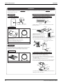
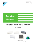
New Stylish Flat Design
harmonizes with interiors
and the simple design does
not make you feel the
existence of A/C in your
room.
Sophisticated edge
Simple display
Straight line
05RAG04- 5
Installation Example
05RAG04- 6
2
Room Air Conditioners D-Series
ED01-505
Features
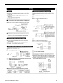
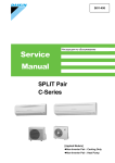
195mm
< Current Model >
273mm
784mm
< New Model >
ign!
ated Des
Sophistic
195mm
283mm
800mm
05RAG04- 7
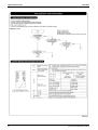
Wipe-clean
Grille Type :
Remove and wash the grille
Current models are
New Flat Panel : Easy to clean without removing the panel
New models are
Also washable after
removing the panel.
05RAG04- 9
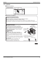
Air-Purifying Filter with Photocatalytic
Deodorizing Function
Double effect : Dust collecting & Deodorizing
Long Lasting Effect
No replacement required
for 3 years with soaking
in water once 6 months.
Needless to Expose to the Sun
Active Component Regenerated
by the Room Light
Material improvement makes
it possible
05RAG04- 10
Room Air Conditioners D-Series
3
Features
ED01-505
Compatibility
Outdoor Unit
Indoor Unit
New
FT25/35DVM
Current
FT25/35BAVM
for 50Hz General
New
Current
R25/35DV1
R25/35JV1
05RAG04- 16
4
Room Air Conditioners D-Series
ED01-505
Power Supply
2. Power Supply
Notes:
Indoor Units
Outdoor Units
Power Supply
FT25DVM
R25DV1
FT35DVM
R35DV1
1φ, 220/240V, 50Hz
Power Supply Intake ; Outdoor Unit
Room Air Conditioners D-Series
5
Functions
ED01-505
Functions
Inverter (with Inverter Power Control)
Basic Function
Compressor
Comfortable
Airflow
Comfort Control
Operation
Lifestyle
Convenience
Functions
—
Air Purifying Filter with Bacteriostatic,
Virustatic Functions
—
—
Photocatalytic Deodorizing Filter
—
PAM Control
—
Air Purifying Filter with Photocatalytic
Deodorizing Function
{
Oval Scroll Compressor
—
Swing Compressor
—
Titanium Apatite Photocatalytic
Air-Purifying Filter
—
Operation Limit for Cooling (°CDB)
19.4
~46
Operation Limit for Heating (°CWB)
Health & Clean
Rotary Compressor
{
Longlife Filter
—
Reluctance DC Motor
—
Mold Proof Air Filter
{
Power-Airflow Flap
—
Wipe-clean Flat Panel
{
Power-Airflow Dual Flaps
{
Washable Grille
—
Power-Airflow Diffuser
—
Mold Proof Operation
—
Wide-Angle Louvers
{
Heating Dry Operation
—
Vertical Auto-Swing (Up and Down)
{
Good-Sleep Cooling Operation
—
Horizontal Auto-Swing (Right and Left)
—
24-Hour ON/OFF Timer
{
Night Set Mode
{
Auto-Restart (after Power Failure)
{
3-D Airflow
—
Comfort Airflow Mode
—
3-Step Airflow (H/P Only)
—
Auto Fan Speed
{
Indoor Unit Silent Operation
—
Night Quiet Mode (Automatic)
—
Timer
Self-Diagnosis (Digital, LED) Display
Worry Free
“Reliability &
Durability”
{
+
Wiring Error Check
—
Anticorrosion Treatment of Outdoor Heat
Exchanger
{
Multi-Split / Split Type Compatible Indoor
Unit
{
Flexible Voltage Correspondence
—
Outdoor Unit Silent Operation (Manual)
—
Intelligent Eye
—
Quick Warming Function
—
Hot-Start Function
—
Automatic Defrosting
—
Chargeless
Automatic Operation
—
Either Side Drain (Right or Left)
{
Programme Dry Function
{
Power Selection
—
Fan Only
{
5-Rooms Centralized Controller (Option)
{
New Powerful Operation (Non-Inverter)
{
Inverter Powerful Operation
—
Remote Control Adaptor
(Normal Open-Pulse Contact)(Option)
{
Priority-Room Setting
—
Cooling / Heating Mode Lock
—
Remote Control Adaptor
(Normal Open Contact)(Option)
{
DIII-NET Compatible (Adaptor)(Option)
—
Home Leave Operation
—
ECONO Mode
—
Indoor Unit On/Off Switch
{
Signal Reception Indicator
{
Temperature Display
—
Another Room Operation
—
Notes: { : Holding Functions
— : No Functions
6
Category
FT25·35DVM
R25·35DV1
Category
FT25·35DVM
R25·35DV1
3. Functions
High Ceiling Application
Flexibility
—
10m
Remote Control
Remote
Controller
Wireless
{
Wired
—
+ : Digital Only
Room Air Conditioners D-Series
ED01-505
Specifications
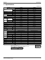
4. Specifications
220/240V, 50Hz
Indoor Units
Models
Outdoor Units
Capacity
Moisture Removal
Running Current
Power Consumption
Power Factor
COP
Liquid
Piping
Connections Gas
Drain
Heat Insulation
Indoor Units
Front Panel Color
kW
Btu/h
kcal/h
L/h
A
W
%
W/W
mm
mm
mm
H
M
L
Air Flow Rate m³/min
(cfm)
Type
Motor Output
Speed
Air Direction Control
Air Filter
Running Current
Power Consumption
Power Factor
Temperature Control
Dimensions (H×W×D)
Packaged Dimensions (H×W×D)
Weight
Gross Weight
Operation
H/L
Sound
Outdoor Units
Casing Color
Type
Compressor Model
Motor Output
Type
Refrigerant
Oil
Charge
Type
Refrigerant
Charge
m³/min
Air Flow Rate
cfm
Type
Fan
Motor Output
Running Current
Power Consumption
Power Factor
Starting Current
Dimensions (H×W×D)
Packaged Dimensions (H×W×D)
Weight
Gross Weight
Operation Sound
Drawing No.
Fan
Notes:
W
Steps
A
W
%
mm
mm
kg
kg
FT25DVM
R25DV1
Cooling
2.62 / 2.62
8,900 / 8,900
2,250 / 2,250
1.2
3.94 / 4.25
815 / 880
94.0 / 86.3
3.21 / 2.98
φ 6.4
φ 9.5
φ18.0
Both Liquid and Gas Pipes
FT25DVM
White
8.8 (311)
7.4 (261)
5.9 (208)
Cross Flow Fan
18
5 Steps, Auto
Right, Left, Horizontal, Downward
Removable / Washable / Mildew Proof
0.17 / 0.15
35 / 35
93.6 / 97.2
Microcomputer Control
283×800×195
265×855×340
9
12
dBA
W
L
kg
W
A
W
%
A
mm
mm
kg
kg
dBA
36 / 28
39 / 31
R25DV1
Ivory White
Hermetically Sealed Rotary Type
RC30BV1R2T
700
SUNISO 4GSD.I.
0.4
R22
0.76
28 /30
988 /1,059
Propeller
25
3.77 / 4.1
780 / 845
94.0 / 85.9
19 / 21
560×695×265
599×797×310
27
30
H : 46 / 48
3D049542
R35DV1
Ivory White
Hermetically Sealed Rotary Type
RC46AV1TRT
1,100
SUNISO 4GSD.I.
0.5
R22
0.95
26.5 / 28
935 / 988
Propeller
25
5.33 / 5.28
1,080 / 1,150
92.1 / 90.8
26 / 28
560×695×265
599×797×310
33
35
H : 48 /49
3D049543
MAX. interunit piping length: 25m
MAX. interunit height difference: 15m
Amount of additional charge of refrigerant 20g/m for piping length exceeding 10m
The data are based on the conditions shown in the table below.
Cooling
Indoor ; 27°CDB/19°CWB
Outdoor ; 35°CDB/24°CWB
Room Air Conditioners D-Series
FT35DVM
R35DV1
Cooling
3.58 / 3.58
1,2200 / 1,2200
3,050 / 3,050
1.9
5.25 / 5.45
1,120 / 1,190
92.2 / 91.0
3.2 / 3.0
φ 6.4
φ 12.7
φ18.0
Both Liquid and Gas Pipes
FT35DVM
White
9.9 (350)
8.3 (293)
6.8 (240)
Cross Flow Fan
18
5 Steps, Auto
Right, Left, Horizontal, Downward
Removable / Washable / Mildew Proof
0.19 / 0.17
40 / 40
95.7 / 98.0
Microcomputer Control
283×800×195
265×855×340
9
12
Piping Length
Conversion Formulae
kcal/h=kW×860
Btu/h=kW×3414
cfm=m³/min×35.3
5m
7
Dimensions
ED01-505
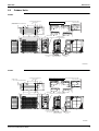
5. Dimensions
5.1
Indoor Units
THE MARK (→) SHOWS PIPING DIRECTION
REAR
30 MIN.
( SPACE FOR
PERFORMANCE )
FT25DVM
AIR FLOW( INDOOR )
800
RIGHT
LEFT
( INCLUDING
MOUNTING PLATE )
197
195
SIGNAL RECEIVER
BOTTOM
FLAPS
TERMINAL BLOCK
WITH EARTH
TERMINAL
GAS PIPE 9. 5Cut
( THE LENGTH OF PIPE OUTSIDE
THE UNIT : ABOUT 390 )
INDOOR UNIT ON/OFF SWITCH
FRONT PANEL FIXED SCREWS
( INSIDE )
50 MIN.
( SPACE FOR
MAINTENANCE )
REQUIRED SPACE
NAME PLATE
283
OPERATION LAMP
TIMER LAMP
50 MIN.
( SPACE FOR
MAINTENANCE )
ROOM TEMP. THERMISTOR( INSIDE )
LIQUID PIPE 6. 4CuT
( THE LENGTH OF PIPE OUTSIDE
THE UNIT : ABOUT 340 )
SIGNAL TRANSMITTER
DRAIN HOSE
( CONNECTING PART
I. D. φ14
O. D. φ18
THE HOSE LENGTH OF OUTSIDE
THE UNIT IS APPROX. 440 )
17
711
49
13
800
BLADE ANGLE
18
58
UP/DOWN( AUTOMATIC )
163
44.5
FAN
283
COOLING, DRY
180
DAIKIN
60
50°
WIRELESS REMOTE CONTROLLER
110
WALL HOLE FOR EMBEDDED PIPING
φ 65 HOLE
70°
STANDARD LOCATIONS OF WALL HOLES
RIGHT/LEFT( MANUAL )
44.5
5°
10°
WALL HOLE
φ 65 HOLE
( ARC433A55 )
45°
45°
3D048857
THE MARK(→) SHOWS PIPING DIRECTION
REAR
30 MIN.
( SPACE FOR
PERFORMANCE )
FT35DVM
AIR FLOW( INDOOR )
800
RIGHT
LEFT
( INCLUDING
MOUNTING PLATE )
197
195
SIGNAL RECEIVER
BOTTOM
FLAPS
INDOOR UNIT ON/OFF SWITCH
FRONT PANEL FIXED SCREWS
( INSIDE )
50 MIN.
( SPACE FOR
MAINTENANCE )
REQUIRED SPACE
NAME PLATE
283
OPERATION LAMP
TIMER LAMP
50 MIN.
( SPACE FOR
MAINTENANCE )
ROOM TEMP. THERMISTOR( INSIDE )
TERMINAL BLOCK
WITH EARTH
TERMINAL
GAS PIPE 12. 7Cut
( THE LENGTH OF PIPE OUTSIDE
THE UNIT : ABOUT 390 )
LIQUID PIPE 6. 4CuT
( THE LENGTH OF PIPE OUTSIDE
THE UNIT : ABOUT 340 )
SIGNAL TRANSMITTER
DRAIN HOSE
( CONNECTING PART
I. D. φ14
O. D. φ18
THE HOSE LENGTH OF OUTSIDE
THE UNIT IS APPROX. 440 )
17
711
49
13
800
BLADE ANGLE
18
58
UP/DOWN( AUTOMATIC )
163
44.5
FAN
283
COOLING, DRY
180
DAIKIN
60
50°
WIRELESS REMOTE CONTROLLER
70°
110
WALL HOLE FOR EMBEDDED PIPING
φ 65 HOLE
STANDARD LOCATIONS OF WALL HOLES
RIGHT/LEFT( MANUAL )
44.5
5°
10°
WALL HOLE
φ 65 HOLE
( ARC433A55 )
45°
45°
3D047960B
8
Room Air Conditioners D-Series
ED01-505
5.2
Dimensions
Outdoor Units
4-HOLES FOR ANCHOR BOLTS
( M8 OR M10 )
WALL HEIGHT ON AIR OUTLET SIDE
= LESS THAN 1200
MINIMUM SPACE FOR AIR PASSAGE
150
50
304
50
50
470
100
50
288
100
20
33
12
420
300
DRAIN OUTLET
( I. Dφ15. 9 HOSE FOR CONNECTION )
150
R25DV1
115
NAME PLATE
695
70
8
265
TERMINAL STRIP
WIRING INLET WITH EARTH TERMINAL
74
78
560
19
118
SERVICE PORT
21
178
GAS STOP VALVE
IN CASE OF REMOVING LIQUID STOP VALVE
( φ9. 5CuT )
( φ6. 4CuT )
STOP VALVE COVER
3D028041B
4-HOLES FOR ANCHOR BOLTS
( M8 OR M10 )
MINIMUM SPACE FOR AIR PASSAGE
WALL HEIGHT ON AIR OUTLET SIDE
= LESS THAN 1200
50
304
50
50
470
100
50
288
100
150
20
33
12
420
300
DRAIN OUTLET
( I. Dφ15. 9 HOSE FOR CONNECTION )
150
R35DV1
115
NAME PLATE
695
70
8
265
WIRING INLET
TERMINAL STRIP
WITH EARTH TERMINAL
SERVICE PORT
GAS STOP VALVE
( φ12. 7CuT )
74
78
560
19
118
178
IN CASE OF REMOVING
STOP VALVE COVER
21
LIQUID STOP VALVE
( φ6. 4CuT )
3D049408
Room Air Conditioners D-Series
9
Wiring Diagrams
ED01-505
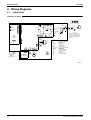
6. Wiring Diagrams
6.1
Indoor Units
FT25DVM / FT35DVM
FIELD WIRING.
S27
PCB3
S26
PCB1
F1U
H1
1
V1
H1P
MR2 H3
LED2
H2P
C70
R1T
2
RED
1
3
WHT
2
BLK
3
V2
GRN /
YLW
OUTDOOR
CAUTION
NOTE THAT OPERATION WILL
RESTART AUTOMATICALLY IF
THE MAIN POWER SUPPLY IS
TURNED OFF AND THEN BACK
ON AGAIN.
FG
RED
S21
WHT
HA
BLK
S7
BLU
t°
PCB2
S29
SIGNAL
RECEIVER
1
S6
R2T
M
M
M1F
t°
140°C
GRY
5
PNK
BLU
S32
RED
S28
ORG
YLW
PPL
WIRELESS
REMOTE
CONTROLLER
H2
SA1
S1
S1W
t°
X1M
3.15A
LED1
C70
FG
F1U
H1P~H2P
M1F
M1S
MR2
PCB1~PCB3
R1T, R2T
S1 ~S38
S1W
SA1
V1, V2
X1M
:
:
:
:
:
:
:
:
:
:
:
:
:
:
:
RUNNING CAPACITOR
FRAME GROUND
FUSE
PILOT LAMP
FAN MOTOR
SWING MOTOR
MAGNETIC RELAY
PRINTED CIRCUIT BOARD
THERMISTOR
CONNECTOR
OPERATION SWITCH
SURGE ARRESTER
VARISTOR
TERMINAL STRIP
PROTECTIVE EARTH
INDOOR
M1S
3D048861
10
Room Air Conditioners D-Series
ED01-505
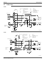
6.2
Wiring Diagrams
Outdoor Units
R25DV1
GRN
YLW
X1M
C11R, C12R : RUNNING CAPACITOR
F1U
: FUSE
K1M
: COMPRESSOR RELAY
M1F
: FAN MOTOR
L
: LIVE
Q1CL
: OVERCURRENT
N
: NEUTRAL
M1C
: COMPRESSOR MOTOR
X1M, X2M
: TERMINAL STRIP
TFU
: THERMAL FUSE
TO INDOOR UNIT
OVERLOAD PROTECTOR
: PROTECTIVE EARTH
RED
1
2
1
BLU
2
WHT
4
3
BLU
C
YLW
3
6
RED
BLK
X2M
L
GRN
YLW
3
3.15A
BLK
L
5
RED
C11R
13
14
BLK
BRN
N
POWER SUPPLY
~ 50Hz
220V-240V
N
Q1CL
BLK
M
M1F
BLK
F1U
M
1~
RED
A2
BLK
A1
M1C
M
1~
S
WHT
C12R
140°C
K1M
BLK
BLK
TFU
76°C
3D024713C
R35DV1
GRN
YLW
C11R, C12R : RUNNING CAPACITOR
F1U
: FUSE
K1M
: COMPRESSOR RELAY
M1F
: FAN MOTOR
L
: LIVE
Q1L
: OVERLOAD PROTECTOR
N
: NEUTRAL
X1M, X2M
: TERMINAL STRIP
M1C
: COMPRESSOR MOTOR
TFU
: THERMAL FUSE
X1M
: PROTECTIVE EARTH
TO INDOOR UNIT
RED
1
2
1
BLU
2
WHT
4
3
BLU
C
3
YLW
6
3
5
BRN
RED
X2M
L
14
BLK
13
BLK
F1U
N
RED
A2
BLK
A1
C12R
K1M
WHT
M
1~
M1F
140°C
BLK
N
M
RED
3.15A
BLK
L
BLK
POWER SUPPLY
~ 50Hz
220V-240V
YLW
GRN
BLK
C11R
M1C
M
1~
S
BLK
Q1L
130°C
TFU
76°C
3D024714C
Room Air Conditioners D-Series
11
Piping Diagrams
ED01-505
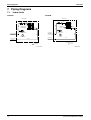
7. Piping Diagrams
7.1
Indoor Units
FT25DVM
FT35DVM
INDOOR UNIT
INDOOR UNIT
MAFFLER ASSY
MAFFLER ASSY
HEAT EXCHANGER
7.0CuT
6.4CuT
(6.4CuT)
THERMISTOR
ON HEAT EXCH.
THERMISTOR
ON HEAT EXCH.
6.4CuT
6.4CuT
CROSS FLOW FAN
FIELD PIPING
(6.4CuT)
M
FIELD PIPING
9.5CuT
CROSSFLOW FAN
M
9.5CuT
(12.7CuT)
(9.5CuT)
REFRIGERANT FLOW
COOLING
C : 4D047912A
12
6.4CuT
FAN MOTOR
FAN MOTOR
FIELD PIPING
6.4CuT
7.9CuT
7.9CuT
6.4CuT
FIELD PIPING
HEATE XCHANGER
7.0CuT
REFRIGERANT FLOW
COOLING
C : 4D047913A
Room Air Conditioners D-Series
ED01-505
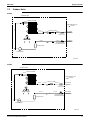
7.2
Piping Diagrams
Outdoor Units
R25DV1
OUTDOOR UNIT
7.9CuT
HEAT EXCHANGER
7.9CuT
9.5CuT
REFRIGERANT FLOW
COOLING
CAPILLARY TUBE
7.9CuT
6.4CuT
7.9CuT
7.9CuT
LIQUID
STOP VALVE
7.9CuT
M
PROPELLER FAN
FIELD PIPING
(6.4CuT)
9.5CuT
9.5CuT
FIELD PIPING
GAS STOP VALVE
WITH SERVICE PORT
(9.5CuT)
ACCUMULATOR
COMPRESSOR
3D020878E
R35DV1
OUTDOOR UNIT
7.9CuT
HEAT EXCHANGER
9.5CuT
7.9CuT
REFRIGERANT FLOW
COOLING
7.9CuT
7.9CuT
CAPILLARY TUBE
6.4CuT
FIELD PIPING
(6.4CuT)
LIQUID
STOP VALVE
7.9CuT
M
PROPELLER FAN
12.7CuT
12.7CuT
GAS STOP VALVE
WITH SERVICE PORT
FIELD PIPING
(12.7CuT)
ACCUMULATOR
COMPRESSOR
3D020877D
Room Air Conditioners D-Series
13
Capacity Tables
ED01-505
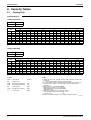
8. Capacity Tables
8.1
Cooling Only
FT25DVM+R25DV1
Cooling (220V 50Hz)
AFR
8.8
BF
0.24
OUTDOOR TEMPERATURE(°CDB)
INDOOR
TEMP
20
25
30
32
35
40
EWB
EDB
TC
SHC
PI
TC
SHC
PI
TC
SHC
PI
TC
SHC
PI
TC
SHC
PI
TC
SHC
PI
°C
°C
kW
kW
kW
kW
kW
kW
kW
kW
kW
kW
kW
kW
kW
kW
kW
kW
kW
kW
14.0
20
2.68
2.00
0.63
2.56
1.94
0.69
2.44
1.88
0.75
2.39
1.86
0.77
2.32
1.82
0.81
2.20
1.76
0.87
16.0
22
2.80
1.97
0.63
2.68
1.91
0.69
2.56
1.85
0.75
2.51
1.83
0.77
2.44
1.80
0.81
2.32
1.74
0.87
18.0
25
2.93
2.06
0.63
2.80
2.01
0.69
2.68
1.95
0.75
2.63
1.93
0.78
2.56
1.90
0.81
2.44
1.85
0.87
19.0
27
2.99
2.17
0.63
2.86
2.12
0.69
2.74
2.07
0.75
2.69
2.05
0.78
2.62
2.02
0.82
2.50
1.97
0.88
22.0
30
3.17
2.10
0.64
3.05
2.05
0.70
2.92
2.01
0.76
2.87
1.99
0.78
2.80
1.96
0.82
2.68
1.92
0.88
24.0
32
3.29
2.04
0.64
3.17
2.00
0.70
3.04
1.96
0.76
2.99
1.94
0.79
2.92
1.92
0.82
2.80
1.88
0.88
Cooling (240V 50Hz)
AFR
8.8
BF
0.24
OUTDOOR TEMPERATURE(°CDB)
INDOOR
TEMP
20
25
30
32
35
40
EWB
EDB
TC
SHC
PI
TC
SHC
PI
TC
SHC
PI
TC
SHC
PI
TC
SHC
PI
TC
SHC
PI
°C
°C
kW
kW
kW
kW
kW
kW
kW
kW
kW
kW
kW
kW
kW
kW
kW
kW
kW
kW
14.0
20
2.68
2.00
0.68
2.56
1.94
0.74
2.44
1.88
0.81
2.39
1.86
0.83
2.32
1.82
0.87
2.20
1.76
0.94
16.0
22
2.80
1.97
0.68
2.68
1.91
0.74
2.56
1.85
0.81
2.51
1.83
0.84
2.44
1.80
0.87
2.32
1.74
0.94
18.0
25
2.93
2.06
0.68
2.80
2.01
0.75
2.68
1.95
0.81
2.63
1.93
0.84
2.56
1.90
0.88
2.44
1.85
0.94
19.0
27
2.99
2.17
0.68
2.86
2.12
0.75
2.74
2.07
0.81
2.69
2.05
0.84
2.62
2.02
0.88
2.50
1.97
0.95
22.0
30
3.17
2.10
0.69
3.05
2.05
0.76
2.92
2.01
0.82
2.87
1.99
0.85
2.80
1.96
0.89
2.68
1.92
0.95
24.0
32
3.29
2.04
0.69
3.17
2.00
0.76
3.04
1.96
0.82
2.99
1.94
0.85
2.92
1.92
0.89
2.80
1.88
0.95
Symbols
AFR
: Air flow rate
BF
: Bypass factor
NOTES:
(m³/min.)
EWB
: Entering wet bulb temp.
(°C)
EDB
: Entering dry bulb temp.
(°C)
TC
: Total capacity
(kW)
SHC
: Sensible heat capacity
(kW)
PI
: Power input
(kW)
1. Ratings shown are net capacities which include a deduction for indoor fan
motor heat.
2.
shows nominal(rated) capacities and power input.
3. TC, PI and SHC must be calculated by interpolation using the figures in
the above tables. (Figures out of the tables should not be used for
calculation.)
4. SHC is based on each EWB and EDB.
SHC∗=SHC correction for other dry bulb.
=0.02×AFR(m³/min.)×(1–BF)×(DB∗–EDB)
Add SHC∗to SHC.
5. Capacities are based on the following conditions.
Corresponding refrigerant piping length : 5m
Level difference
: 0m
6. Air flow rate (AFR) and bypass factor (BF) are tabulated above.
3D049930
14
Room Air Conditioners D-Series
ED01-505
Capacity Tables
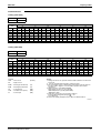
FT35DVM+R35DV1
Cooling (220V 50Hz)
AFR
9.9
BF
0.24
OUTDOOR TEMPERATURE(°CDB)
INDOOR
TEMP
20
25
30
32
35
40
EWB
EDB
TC
SHC
PI
TC
SHC
PI
TC
SHC
PI
TC
SHC
PI
TC
SHC
PI
TC
SHC
PI
°C
°C
kW
kW
kW
kW
kW
kW
kW
kW
kW
kW
kW
kW
kW
kW
kW
kW
kW
kW
14.0
20
3.67
2.58
0.86
3.50
2.50
0.94
3.33
2.41
1.02
3.27
2.37
1.06
3.17
2.32
1.11
3.00
2.24
1.19
16.0
22
3.83
2.54
0.86
3.67
2.46
0.95
3.50
2.37
1.03
3.43
2.34
1.06
3.33
2.29
1.11
3.17
2.21
1.20
18.0
25
4.00
2.64
0.87
3.83
2.56
0.95
3.66
2.48
1.03
3.60
2.45
1.07
3.50
2.41
1.12
3.33
2.33
1.20
19.0
27
4.08
2.76
0.87
3.91
2.68
0.95
3.75
2.61
1.04
3.68
2.58
1.07
3.58
2.54
1.12
3.41
2.47
1.20
22.0
30
4.33
2.65
0.88
4.16
2.59
0.96
3.99
2.52
1.04
3.93
2.49
1.08
3.83
2.46
1.13
3.66
2.39
1.21
24.0
32
4.49
2.58
0.88
4.33
2.51
0.97
4.16
2.45
1.05
4.09
2.43
1.08
3.99
2.40
1.13
3.83
2.34
1.22
Cooling (240V 50Hz)
AFR
9.9
BF
0.24
OUTDOOR TEMPERATURE(°CDB)
INDOOR
TEMP
20
25
30
32
35
40
EWB
EDB
TC
SHC
PI
TC
SHC
PI
TC
SHC
PI
TC
SHC
PI
TC
SHC
PI
TC
SHC
PI
°C
°C
kW
kW
kW
kW
kW
kW
kW
kW
kW
kW
kW
kW
kW
kW
kW
kW
kW
kW
14.0
20
3.67
2.58
0.91
3.50
2.50
1.00
3.33
2.41
1.09
3.27
2.37
1.12
3.17
2.32
1.18
3.00
2.24
1.26
16.0
22
3.83
2.54
0.92
3.67
2.46
1.01
3.50
2.37
1.09
3.43
2.34
1.13
3.33
2.29
1.18
3.17
2.21
1.27
18.0
25
4.00
2.64
0.92
3.83
2.56
1.01
3.66
2.48
1.10
3.60
2.45
1.13
3.50
2.41
1.19
3.33
2.33
1.28
19.0
27
4.08
2.76
0.93
3.91
2.68
1.01
3.75
2.61
1.10
3.68
2.58
1.14
3.58
2.54
1.19
3.41
2.47
1.28
22.0
30
4.33
2.65
0.93
4.16
2.59
1.02
3.99
2.52
1.11
3.93
2.49
1.15
3.83
2.46
1.20
3.66
2.39
1.29
24.0
32
4.49
2.58
0.94
4.33
2.51
1.03
4.16
2.45
1.12
4.09
2.43
1.15
3.99
2.40
1.20
3.83
2.34
1.29
Symbols
AFR
: Air flow rate
BF
: Bypass factor
NOTES:
(m³/min.)
EWB
: Entering wet bulb temp.
(°C)
EDB
: Entering dry bulb temp.
(°C)
TC
: Total capacity
(kW)
SHC
: Sensible heat capacity
(kW)
PI
: Power input
(kW)
1. Ratings shown are net capacities which include a deduction for indoor fan
motor heat.
2.
shows nominal(rated) capacities and power input.
3. TC, PI and SHC must be calculated by interpolation using the figures in
the above tables. (Figures out of the tables should not be used for
calculation.)
4. SHC is based on each EWB and EDB.
SHC∗=SHC correction for other dry bulb.
=0.02×AFR(m³/min.)×(1–BF)×(DB∗–EDB)
Add SHC∗to SHC.
5. Capacities are based on the following conditions.
Corresponding refrigerant piping length : 5m
Level difference
: 0m
6. Air flow rate (AFR) and bypass factor (BF) are tabulated above.
3D049931
Room Air Conditioners D-Series
15
Capacity Tables
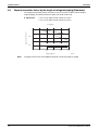
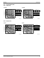
8.2
ED01-505
Capacity correction factor by the length of refrigerant piping (Reference)
The cooling and the heating capacity of the unit has to be corrected in accordance with the length of
refrigerant piping. (The distance between the indoor unit and the outdoor unit)
Split System
<— line : For the indoor unit with capacity of 2.5 kW. >
<--- line : For the indoor unit with capacity of 3.5 kW. >
Cooling (R22)
Capacity correction factor
1
0.9
Range of the Refrigerant Additional Charge
0.8
5
10
15
Piping length (m)
Notes:
16
20
25
(R2501)
The graph shows the factor when additional refrigerant of the proper quantity is charged.
Room Air Conditioners D-Series
ED01-505
Operation Limit
9. Operation Limit
R25DV1 / R35DV1
50
40
30
Pull-down period
Continuous operation
Outdoor temp. (°CDB)
46
20
19.4
0
10
14
Notes:
The graph is based
on the following conditions.
• Equivalent piping length
5m
• Level difference
0m
• Air flow rate
High
20
23
28 30
Indoor temp. (°CWB)
4D000888P
Room Air Conditioners D-Series
17
Sound Level
ED01-505
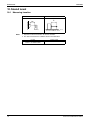
10. Sound Level
10.1 Measuring Location
Indoor Unit
Outdoor Unit
Wall Mounted Type
1m
0.8m
1m
(R1759)
Notes:
1. Operation sound is measured in an anechoic chamber.
2. The data are based on the conditions shown in the table below.
Cooling
Indoor ; 27°CDB/19°CWB
Outdoor ; 35°CDB/24°CWB
18
(R1003)
Piping Length
5m
Room Air Conditioners D-Series
ED01-505
Sound Level
10.2 Octave Band Level
10.2.1 Indoor Units
FT25DVM
FT35DVM
70
OVER ALL(dB)
NC-60
60
NC-50
50
SCALE
50Hz
220-240v
(H)
50Hz
220-240v
(L)
A
36
28
(B.G.N IS ALREADY RECTIFIED)
OPERATING CONDITIONS
NC-40
POWER SOURCE 220-240V 50Hz
40
JIS STANDARD
STANDARD EXTERNAL STATIC PRESSURE
50Hz 220-240v(H)
NC-30
30
50Hz 220-240v(L)
NC-20
20
APPROXIMATE
THRESHOLD HEARING
FOR CONTINUOUS
NOISE
63
125
250
500
1000
2000
4000
OCTAVE BAND SOUND PRESSURE LEVEL
dB(0dB=0.0002µ bar)
OCTAVE BAND SOUND PRESSURE LEVEL
dB(0dB=0.0002µ bar)
70
OVER ALL(dB)
NC-60
60
NC-50
50
SCALE
50Hz
220-240v
(H)
50Hz
220-240v
(L)
A
39
31
(B.G.N IS ALREADY RECTIFIED)
OPERATING CONDITIONS
NC-40
POWER SOURCE 220-240V 50Hz
40
JIS STANDARD
50Hz 220-240v(H)
NC-30
30
50Hz 220-240v(L)
Cooling
NC-20
20
8000
OCTAVE BAND CENTER FREQUENCY (Hz)
APPROXIMATE
THRESHOLD HEARING
FOR CONTINUOUS
NOISE
63
125
250
500
1000 2000 4000
OCTAVE BAND CENTER FREQUENCY (Hz)
8000
4D048829
4D048281A
10.2.2 Outdoor Units
R25DV1
R35DV1
70
NC-60
60
NC-50
SCALE
50Hz
220V
50Hz
240V
A
46
48
(B.G.N IS ALREADY RECTIFIED)
OPERATING CONDITIONS
50
POWER SOURCE 220-240V 50Hz
NC-40
JIS STANDARD
40
50Hz 220V
NC-30
50Hz 240V
30
NC-20
20
OVER ALL(dB)
OVER ALL(dB)
APPROXIMATE
THRESHOLD HEARING
FOR CONTINUOUS
NOISE
63
125
250
500
1000 2000 4000
OCTAVE BAND CENTER FREQUENCY (Hz)
NC-60
60
NC-50
SCALE
50Hz
220V
50Hz
230V
50Hz
240V
A
48
48
49
(B.G.N IS ALREADY RECTIFIED)
OPERATING CONDITIONS
50
POWER SOURCE 220-240V 50Hz
NC-40
JIS STANDARD
40
50Hz 220V • 230V
50Hz 240V
NC-30
30
NC-20
20
APPROXIMATE
THRESHOLD HEARING
FOR CONTINUOUS
NOISE
63
8000
4D029157B
Room Air Conditioners D-Series
OCTAVE BAND SOUND PRESSURE LEVEL
dB(0dB=0.0002µ bar)
OCTAVE BAND SOUND PRESSURE LEVEL
dB(0dB=0.0002µ bar)
70
125
250
500
1000 2000 4000
OCTAVE BAND CENTER FREQUENCY (Hz)
8000
4D000697D
19
Electric Characteristics
ED01-505
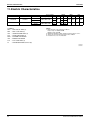
11. Electric Characteristics
Power Supply
Indoor Unit
Outdoor Unit
FT25DVM
R25DV1
FT35DVM
R35DV1
Hz-Volts
Voltage Range
MCA
50-220
MAX. 50Hz 264V
MIN. 50Hz 198V
4.7
MAX. 50Hz 264V
MIN. 50Hz 198V
6.7
50-240
50-220
50-240
5.2
6.7
COMP
MFA
15
15
LRA
RLA
19
3.4
21
3.8
26
5.0
28
5.0
OFM
IFM
W
FLA
W
FLA
25
0.27
18
0.16
25
0.27
18
0.16
SYMBOLS:
NOTES:
MCA
1. RLA is based on the following conditions.
Indoor temp. 27°CDB/19°CWB
Outdoor temp. 35°CDB.
2. Maximum allowable voltage variation between phases is 2%.
3. Select wire size based on the larger value of MCA.
4. Instead of fuse, use circuit breaker.
: MIN. CIRCUIT AMPS (A)
MFA
: MAX. FUSE AMPS (A)
LRA
: LOCKED ROTOR AMPS (A)
RLA
: RATED LOAD AMPS (A)
OFM
: OUTDOOR FAN MOTOR
IFM
: INDOOR FAN MOTOR
FLA
: FULL LOAD AMPS (A)
W
: FAN MOTOR RATED OUTPUT (W)
3D049939
3D049940
20
Room Air Conditioners D-Series
ED01-505
Installation Manual
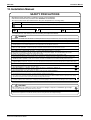
12. Installation Manual
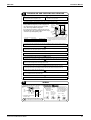
SAFETY PRECAUTIONS
• Read these Safety Precautions carefully to ensure correct installation.
• This manual classifies the precautions into WARNING and CAUTION.
Be sure to follow all the precautions below: they are all important for ensuring safety.
WARNING
Failure to follow any of WARNING is likely to result in such grave consequences as death or serious injury.
CAUTION
Failure to follow any of CAUTION may result in grave consequences in some cases.
• The following safety symbols are used throughout this manual:
Be sure to observe this instruction.
Be sure to establish an earth connection.
Never attempt.
• After completing installation, test the unit to check for installation errors. Give the user adequate instructions
concerning the use and cleaning of the unit according to the Operation Manual.
WARNING
• Installation should be left to the dealer or another professional. Improper installation may cause water leakage, electrical shock, or fire.
• Install the air conditioner according to the instructions given in this manual. Incomplete installation may cause water leakage, electrical shock, or fire.
• Be sure to use the supplied or specified installation parts. Use of other parts may cause the unit to come to lose, water leakage, electrical shock, or fire.
• Install the air conditioner on a solid base that can support the weight of the unit.
An inadequate base or incomplete installation may cause injury in the event the unit falls off the base.
• Electrical work should be carried out in accordance with the installation manual and the national electrical wiring
rules or code of practice. Insufficient capacity or incomplete electrical work may cause electrical shock or fire.
• Be sure to use a dedicated power circuit. Never use a power supply shared by another appliance.
• For wiring, use a cable length enough to cover the entire distance with no connection.
Do not use an extension cord. Do not put other loads on the power supply, use a dedicated power circuit.
(Failure to do so may cause abnormal heat, electrical shock or fire.)
• Use the specified types of wires for electrical connections between the indoor and outdoor units.
Firmly clamp the interconnecting wires so their terminals receive no external stresses. Incomplete connections or clamping may cause terminal overheating or fire.
• After connecting interconnecting and supply wiring be sure to shape the cables so that they do not put undue force on the
electrical covers or panels. Install covers over the wires. Incomplete cover installation may cause terminal overheating, electrical shock, or fire.
• When installing or relocating the system, be sure to keep the refrigerant circuit free from substances other than the specified
refrigerant (R22), such as air. (Any presence of air or other foreign substance in the refrigerant circuit causes an abnormal pressure rise or rupture, resulting in injury.)
• The installation height from the floor must be over 1.8m.
• If any refrigerant has leaked out during the installation work, ventilate the room.
(The refrigerant produces a toxic gas if exposed to flames.)
• After all installation is complete, check to make sure that no refrigerant is leaking out.
(The refrigerant produces a toxic gas if exposed to flames.)
• During pump-down, stop the compressor before removing the refrigerant piping.
If the compressor is still running and the shut-off valve is open during pump-down, air will be sucked in when the refrigerant piping is removed,
causing abnormal pressure in the freezer cycle which will lead to breakage and even injury.
• During installation, attach the refrigerant piping securely before running the compressor.
If the compressor is not attached and the shut-off valve is open during pump-down, air will be sucked in when the compressor is run, causing
abnormal pressure in the freezer cycle which will lead to breakage and even injury.
• Be sure to establish an earth. Do not earth the unit to a utility pipe, arrester, or telephone earth.
Incomplete earth may cause electrical shock. A high surge current from lightning or other sources may cause damage to the air conditioner.
• Be sure to install an earth leakage breaker. Failure to install an earth leakage breaker may result in electrical shocks.
CAUTION
• Do not install the air conditioner in a place where there is danger of exposure to inflammable gas leakage.
If the gas leaks and builds up around the unit, it may catch fire.
• Establish drain piping according to the instructions of this manual. Inadequate piping may cause flooding.
• Tighten the flare nut according to the specified method such as with a torque wrench.
If the flare nut is tightened too hard, the flare nut may crack after a long time and cause refrigerant leakage.
Room Air Conditioners D-Series
21
Installation Manual
ED01-505
ACCESSORIES
Indoor unit
A
~L
A Mounting plate
1
E Remote controller holder
1
J Insulation tape
1
B Mounting plate fixing
screw M4 × 25L
6
F Fixing screw for remote controller
holder M3 × 20L
2
K Operation manual
1
C Air purifying filter with
photocatalytic deodorizing function
2
G AAA dry-cell batteries
2
L Installation manual
1
D Wireless remote controller
1
H Indoor unit fixing screw
M4 × 12L
2
CHOOSING A SITE
• Before choosing the installation site, obtain user approval.
Indoor unit
Outdoor unit
The indoor unit should be sited in a place where:
• the restrictions on installation specified in the
indoor unit installation drawings are met,
• both air intake and exhaust have clear paths of air,
• the unit is not in the path of direct sunlight,
• the unit is away from the source of heat or steam,
• there is no source of machine oil vapour (this may
shorten indoor unit life),
• cool air is circulated throughout the room,
• the unit is away from electronic ignition type
fluorescent lamps (inverter or rapid start type) as
they may shorten the remote controller range,
• the unit is at least 1 metre away from any television
or radio set (unit may cause interference with the
picture or sound)
• install at the recommended height (1.8m).
The outdoor unit should be sited in a place where:
• the restrictions on installation specified in the outdoor unit installation diagram are met,
• drain water causes no trouble or problem in particular,
• both air intake and exhaust have clear paths of air (they should be free of snow in
snowy districts),
• the unit is in a clear path of air but not directly exposed to rain, strong winds, or direct
sunlight,
• there is no fear of inflammable gas leakage,
• the unit is no directly exposed to salt, sulfidized gases, or machine oil vapour (they
may shorten outdoor unit life).
• operation noise or hot air flow does not cause trouble to neighbours,
• the unit is at least 3 metres away from any television or radio antenna.
Wireless Remote Controller
• Turn on all the fluorescent lamps in the room, if any, and find the site where remote
control signals are properly received by the indoor unit (within 7 metres).
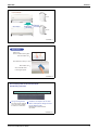
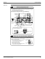
INSTALLATION TIPS
<When there is no work space because the unit is close to ceiling>
1. Removing and installing front panel.
• Removal method
Caution
Hook fingers on the panel protrusions on the left and right of the main body,
and open until the panel stops. Slide the front panel sideways to disengage
the rotating shaft. Then pull the front
panel toward you to remove it.
1) Push up.
Be sure to wear protection gloves.
Place both hands under the center of the front
grille, and while pushing up, pull it toward you.
2) Pull toward you.
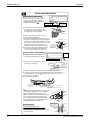
• Installation method
1) Install the front grille and firmly engage the upper hooks (3 locations).
2) Install 2screws of the front grille.
3) Install the air filter and then mount the front panel.
• Installation method
tab(3)
Push the
rotating shaft
of the front
panel into the
groove.
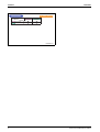
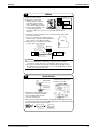
3. How to set the different
addresses.
• Removal method
1) Remove front panel to remove the air filter.
2) Remove the front grille.
3) In front of the
mark of the front grille,
there are 3 upper hooks. Lightly pull the
front grille toward you with one hand, and
push down on the hooks with the fingers of
your other hand.
22
mark area
(3 locations)
Upper hook
Lightly pull the front
grille toward you with
one hand, and push
down on the hooks with
the fingers of your other
hand. (3 locations)
Push
down.
Upper hook
Upper hook
PCB
Address
2. Removing and installing front grille.
When two indoor units are
installed in one room, the two
wireless remote controllers
can be set for different
addresses.
1) Remove the front grille.
(2 screws)
2) Remove the electrical
wiring box. (1 screw)
3) Remove the metal plate
electrical wiring cover.
(3 tabs)
4) Cut the address jumper (JA)
on the printed circuit board.
5) Cut the address jumper
(J4) in the remote controller.
Electrical
wiring box
JA
Align the tabs of the front panel with the
grooves, and push all the way in. Then close
slowly. Push the center of the lower surface
of the panel firmly to engage the tabs.
JA Address
EXIST
CUT
1
2
Metal
cover
Screw
J4
J4 ADDRESS
EXIST
CUT
1
2
Room Air Conditioners D-Series
ED01-505
Installation Manual
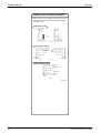
INDOOR/OUTDOOR UNIT INSTALLATION DRAWINGS
A Mounting plate
How to attach the indoor unit.
Hook the claws of the bottom frame
to the mounting plate.
If the claws are difficult to hook,
remove the front grille.
The mounting plate should be installed
on a wall which can support the weight
of the indoor unit.
B Mounting plate fixing
screws M4 × 25L (6)
How to remove the indoor unit.
Push up the marked area (at the
lower part of the front grille) to
release the claws. If it is difficult to
release, remove the front grille.
30mm or more
from ceiling
A Mounting
plate
Clip
Bottom frame
Front grille
Mark (rear side)
Front panel
Cut thermal insulation pipe to an appropriate length and wrap it with
tape, making sure that no gap is left in the insulation pipe’s cut line.
Caulk pipe
hole gap
with putty.
50mm or more from walls
(on both sides)
Air filters
C Air purifying filter with photocatalytic deodorizing function
Wrap the insulation pipe with the finishing
tape from bottom to top.
Service lid
Opening service lid
Service lid is opening/closing
type.
Opening method
1) Remove the service lid
screws.
2) Pull out the service lid
diagonally down in the
direction of the arrow.
3) Pull down.
R35
25m
Max. allowable length
Max. allowable height
15m
Additional refrigerant required for
refrigerant pipe exceeding 10m in length.
Gas pipe
Install Air purifying filter with photocatalytic
deodorizing function on air filter
Liquid pipe
20g/m
O.D. 9.5mm
O.D. 12.7mm
O.D. 6.4mm
* Be sure to add the proper amount of additional refrigerant. Failure to do so may
result in reduced performance.
Air filter
Filter frame
R25
Model
C Air purifying filter with
photocatalytic
deodorizing function
Tab
* Appearance of the outdoor unit
may differ from some models.
Before screwing the remote
controller holder to the wall,
make sure that control
signals are properly
received by indoor unit.
D Wireless
remote controller
1 Insert.
Service lid
How to remove the service lid.
• Remove the screw on the service lid.
• Slide the lid downward to remove it.
E
Remote
controller holder
How to attach the service lid.
• Insert the upper part of the service lid
into the outdoor unit to install.
• Tighten the screws.
250mm from wa
ll
F
(M3 × 20L)
In sites with poor drainage, use block
bases for outdoor unit.
Adjust foot height until the unit is
leveled. Otherwise, water leakage
or pooling of water may occur.
470
(Foot b
olt-hole
e
hol
oltot b
F( o ters)
cen
8
28
centers
)
115
(From
unit’s si
de
Allow space for piping
and electrical servicing.
Where there is a danger of the unit falling,
use foot bolts, or wires.
)
Unit: mm
Room Air Conditioners D-Series
23
Installation Manual
ED01-505
Outdoor Unit Installation Guidelines
• Where a wall or other obstacle is in the path of outdoor
unit’s intake or exhaust airflow, follow the installation
guidelines below.
Wall facing one side
More than 50
More than 100
Side view
Walls facing two sides
More than 100
More
than 150
More than 50
More than 50
Top view
Walls facing three sides
More than 150
More than 300
More
than 50
Top view
Unit: mm
24
Room Air Conditioners D-Series
ED01-505
Installation Manual
Indoor Unit
1
INSTALLING THE MOUNTING PLATE
• The mounting plate should be installed on a wall which can support the weight of the indoor unit.
(1) Temporarily secure the mounting plate to the wall, make sure that the panel is completely
level, and mark the boring points on the wall.
(2) Secure the mounting plate to the wall with screws.
Recommended mounting-plate retention spots and Dimensions
450
Recommended
mounting - plate
retention spots
(6 spots in all)
100
400
(Bolt size : M10)
135
110
φ65
60
φ65
130
220
60
44.5
Use tape
measure
as shown.
Position the
end of a tape
measure at
131.5
44.5 87
283
47.5
46.5
(Bolt size : M10)
50.5
80
141.5
Place a leveler
on raised tab.
110
50
800
Drain hose
position
Throughthe-wall
hole 65mm
Liquid pipe end Keep here the piece cut out
from the unit for piping.
Gas pipe end
* The removed pipe port cover can be
kept in the mounting plate pocket.
Removed pipe
port cover.
A Mounting plate
2
BORING A WALL HOLE AND INSTALLING WALL EMBEDDED PIPE
• For walls containing metal frame or metal board, be sure to use a wall embedded pipe and
wall cover in the feed-through hole to prevent possible heat, electrical shock, or fire.
• Be sure to caulk the gaps around the pipes with caulking
Inside
Outside
material to prevent water leakage.
Wall embedded pipe
(1) Bore a feed-through hole of 65mm in the wall so
it has a down slope toward the outside.
(2) Insert a wall pipe into the hole.
(3) Insert a wall cover into wall pipe.
(4) After completing refrigerant piping, wiring, and drain
piping, caulk pipe hole gap with putty.
Room Air Conditioners D-Series
(field supply)
Caulking
φ65
Wall hole cover
(field supply)
Wall embedded pipe
(field supply)
25
Installation Manual
ED01-505
3
INSTALLING INDOOR UNIT
Right-Side, Right-Back, or Right-Bottom Piping
(1) Attach the drain hose to the underside of the
refrigerant pipes with adhesive vinyl tape.
(2) Wrap the refrigerant pipes and drain hose
Remove pipe port cover
together with insulation tape J .
here for right-side piping
Right-back piping
Bind coolant pipe and
drain hose together with
insulating tape.
Right-bottom piping
Remove pipe port cover here for right-bottom piping
A Mounting plate
(3) Pass the drain hose and refrigerant pipes through
the wall hole, then set the indoor unit on the
mounting plate hooks by using the markings at
the top of the indoor unit as a guide.
(4) Open the front grille, then open the service lid.
(Refer to INSTALLATION TIPS.)
(5) Pass the interconnecting wires from the outdoor unit
Hang indoor unit's hook here.
through the feed-through wall hole and then through the
back of the indoor unit. Pull them through the front side.
Bend the ends of tie wires upward in advance for easier
A Mounting
work. (If the interconnecting wire ends are to be
plate
When stripping the
ends of interconnecting
stripped first, bundle wire ends with adhesive tape.)
wires in advance, bind
Interconnecting
right ends of wires with
(6) Press the indoor unit’s bottom panel with both hands
wires
insulating tape.
Wire guide
to set it on the mounting plate hooks. Make sure the
wires do not catch on the edge of the indoor unit.
Left-Side, Left-Back, or Left Bottom Piping
Remove pipe
port cover here
for left-side
piping
(1) Attach the drain hose to the underside of
the refrigerant pipes with adhesive vinyl tape.
Left-side
piping
Remove pipe port cover here for left-bottom piping
Left-back
piping
Left-bottom piping
(2) Be sure to connect the drain hose to the drain
port in place of a drain plug.
• How to set drain plug
ap
No g
Do not apply lubricating
oil (refrigerant machine
oil) when inserting.
Application of causes
deterioration and drain
leakage of the plug.
Insert a hexagon wrench (4mm)
(3) Shape the refrigerant pipe along the pipe path marking on the mounting plate.
(4) Pass drain hose and refrigerant pipes through the wall hole, then set the indoor unit on
mounting plate hooks, using the markings at the top of indoor unit as a guide.
(5) Pull in the interconnecting wires.
(6) Connect the inter-unit piping.
Drain
hose
Caulk this hole
with putty or
caulking material.
A Mounting plate
Bind with plastic
tape.
Wrap insulating tape around the bent portion
of refrigerant pipe.
Overlap at least half the width of the tape
with each turn.
Note:
• Wrap the refrigerant pipes and drain hose together with
insulation tape as right figure, in case of setting the
drain hose through the back of the indoor unit.
• While exercising care so that the interconnecting wires
do not catch indoor unit, press the bottom edge of
indoor unit with both hands until it is firmly caught by
the mounting plate hooks. Secure indoor unit to the
mounting plate with the screws (M4 × 12L).
Wall Embedded Piping
Follow the instructions given under
Left-Side, Left-Back, or Left Bottom Piping .
• Insert the drain hose to this depth so it won’t be pulled
out of the drain pipe.
26
Drain hose
A
Mounting
plate
Refrigerant
pipes
Bottom frame
H M4 × 12L (2 point)
Insert drain hose to this
depth so it won’t be
pulled out of drain pipe.
50mm
or more
Outer wall
Inner wall
Drain hose
Vinyl chloride
drain pipe
(VP-30)
Room Air Conditioners D-Series
ED01-505
Installation Manual
4
WIRING
S21
1) Strip wire ends (15mm).
Terminal block
Electrical component box
2) Match wire colours with
Shape wires so
terminal numbers on indoor
that the service
lid will fit securely.
and outdoor unit’s terminal
Connector for fan motor
blocks and firmly screw wires
Firmly secure wire retainer
so that wires sustain no
to the corresponding terminals.
Use the
external stress.
specified
3) Connect the earth wires to the
Wire retainer
wire type.
corresponding terminals.
Attach the earth wire so that it is not connected to the fan motor
connector.
4) Pull wires to make sure that they are securely latched up, then retain
wires with wire retainer.
5) In case of connecting to an adapter system.
Run the remote controller cable and attach the
S21 connector as the illustration right.
PCB
6) Shape the wires so that the service lid fits
securely, then close service lid.
Firmly fix the wires with
the terminal screws.
Outdoor unit
1 23
When wire length exceeds
10m, use 2.0-mm wires.
Indoor
unit
LN
1
2
3
Safety
breaker
15A
Earth leakage
circuit breaker
Power
supply
50Hz 230V
H05VV
Firmly fix the wires with
the terminal screws.
Earth
Warning
1) Do not use tapped wires, stand wires, extensioncords, or starbust
connections, as they may cause overtheating, electrical shock,or fire.
2) Do not use locally purchased electrical parts inside the product. (Do not
branch the power for the drain pump, etc., from the terminal block.) Doing
so may cause electric shock or fire.
5
DRAIN PIPING
• Connect the drain hose, as described below.
The drain hose should
be inclined downward.
• Remove the air filters and pour some
water into the drain pan to check
the water flows smoothly.
No trap is permitted.
Do not put the end
of the hose in water.
• When drain hose requires extension, obtain
an extension hose commercially available.
Be sure to thermally insulate the indoor
section of the extension hose.
Extension drain hose
Indoor unit
drain hose
Heat insulation tube
(Field supply)
φ18
• When connecting a rigid polyvinyl chloride pipe (nominal diameter 13mm) directly to the drain
hose attached to the indoor unit as with embedded piping work, use any commercially available
drain socket (nominal diameter 13mm) as a joint.
Drain hose supplied with
the indoor unit
Room Air Conditioners D-Series
Commercially available
drain socket
(nominal diameter 13mm)
Commercially available rigid
polyvinyl chloride pipe
(nominal diameter 13mm)
27
Installation Manual
ED01-505
Outdoor Unit
1
INSTALLING OUTDOOR UNIT
• For outdoor unit installation, see CHOOSING A SITE , Outdoor unit
and INDOOR/OUTDOOR UNIT INSTALLATION DRAWINGS .
2
FLARING THE PIPE END
1. Cut the pipe end with a pipe cutter.
2. Remove burrs with the cut surface facing downward
so that the chips do not enter the pipe.
3. Put the flare nut on the pipe.
4. Flare the pipe.
5. Check that the flaring is properly made.
(Cut exactly at
right angles.)
Remove burrs
Flaring
Set exactly at the position shown below.
A
Die
A
RIGID
0.5mm
IMPERIAL
1.0mm
Check
Warning
Flare’s inner surface
must be flaw-free.
Incomplete flaring may cause refrigerant gas leakage.
The pipe end must
be evenly flared in
a perfect circle.
Make sure that the
flare nut is fitted.
3
REFRIGERANT PIPING
1. Align the centers of both flares and tighten
the flare nuts 3 or 4 turns by hand. Then
tighten them fully with the torque wrenches.
• Use torque wrenches when tightening the
flare nuts to prevent damage to the flare
nuts and escaping gas.
2. To prevent gas leakage, apply refrigeration
machine oil on both inner and outer surfaces
of the flare.
Flare nut tightening torque
Gas side
Liquid side
3/8 inch
1/2 inch
1/4 inch
32.7-39.9N•m
49.5-60.3N•m
14.2-17.2N•m
(333-407kgf•cm) (505-615kgf•cm) (144-175kgf•cm)
Valve cap tightening torque
Liquid side
Gas side
3/8 inch
1/2 inch
1/4 inch
21.6-27.4N•m
26.5-32.3N•m
21.6-27.4N•m
(220-280kgf•cm) (270-330kgf•cm) (220-280kgf•cm)
Service port cap tightening torque 10.8-14.7N•m (110-150kgf•cm)
Cautions on Pipe Handling
• Protect the open end of the pipe against
dust and moisture.
Rain
• All pipe bends should be as gentle as
possible. Use a pipe bender for bending.
(Bending radius should be 30 to 40mm or larger.)
Be sure to
place a cap.
Wall
If no flare cap is
available, cover
the flare mouth
with tape to keep
dirt or water out.
Selection of Copper and Heat Insulation materials
When using commercial copper pipes and fittings, observe the following:
• Insulation material: Polyethylene foam
Heat transfer rate: 0.041 to 0.052kW/mK (0.035 to 0.045kcal/mh˚C)
Refrigerant gas pipe’s surface temperature reaches 110˚C max.
Choose heat insulation materials that will withstand this temperature.
• Be sure to insulate both the gas and liquid piping and to provide insulation dimensions as below.
Gas side
25 class
35 class
O.D. 9.5mm
O.D. 12.7mm
Thickness 0.8mm
Liquid side
O.D. 6.4mm
Thickness
0.8mm
35 class
Liquid pipe
thermal
insulation
I.D. 14-16mm
I.D. 8-10mm
Gas pipe thermal insulation
25 class
I.D. 12-15mm
• Use separate thermal insulation pipes for gas and liquid
refrigerant pipes.
Thickness 10mm Min.
Gas pipe Inter-unit wiring
Liquid pipe
Gas pipe
insulation
Finishing tape
28
Liquid pipe
insulation
Drain hose
Room Air Conditioners D-Series
ED01-505
Installation Manual
4
PURGING AIR AND CHECKING GAS LEAKAGE
Warning
Warning
Do not mix any substance other than the specified
refrigerant (R22) into the refrigeration cycle.
If refrigerant gas leaks during air purging, ventilate
the room as soon as possible.
To prevent air pollution, a vacuum pump should be used for air purging wherever possible.
• If using additional refrigerant, perform air purging from
the refrigerant pipes and indoor unit using a vacuum
pump, then charge additional refrigerant.
• Use a hexagonal wrench (4mm) to operate the shut-off valve rod.
• All refrigerant pipe joints should be tightened with a torque
wrench at the specified tightening torque.
Pressure
Compound
meter
pressure gauge
Gauge
manifold
Low-pressure
valve
Highpressure
valve
Valve lids
Charging
hoses
Service Gas
shut-off
Vacuum pump port
valve
*1. Pipe length vs. vacuum pump run time
Pipe length
Up to 15 metres
More than 15 metres
Run time
Not less than 10 min.
Not less than 15 min.
Liquid
shut-off
valve
*2. If the compound pressure gauge pointer swings back, refrigerant
may have water content or a loose pipe joint may exists. Check
all pipe joints and retighten nuts as needed, then repeat steps (2)
through (4).
(1) Connect projection side (on which worm pin is pressed) of charging hose (which comes from gauge manifold) to
gas shut-off valve’s service port.
(2) Fully open gauge manifold’s low-pressure valve (Lo) and completely close its high-pressure valve (Hi).
(High-pressure valve subsequently requires no operation.)
(3) Do vacuum pumping and make sure that the compound pressure gauge reads –0.1MPa (–76cmHg)*1.
(4) Close gauge manifold’s low-pressure valve (Lo) and stop vacuum pump.
(Keep this state for a few minutes to make sure that the compound pressure gauge pointer does not swing back.)*2.
(5) Remove covers from liquid shut-off value and gas shut-off valve.
(6) Turn the liquid shut-off valve’s rod 90 degrees counterclockwise with a hexagonal wrench to open valve.
Close it after 5 seconds, and check for gas leakage.
Using soapy water, check for gas leakage from indoor unit’s flare and outdoor unit’s flare and valve rods.
After the check is complete, wipe all soapy water off.
(7) Disconnect charging hose from gas shut-off valve’s service port, then fully open liquid and gas shut-off valves.
(Do not attempt to turn valve rod beyond its stop.)
(8) Tighten valve lids and service port caps for the liquid and gas shut-off valves with a torque wrench at the specified torques.
5
WIRING
• For interconnecting wire connections, see INDOOR UNIT , 4. WIRING .
Terminal block
(For interconnecting
wire)
Wire
clamp
band
Terminal block
(For power supply)
Ground terminal
Service
lid
• How to tighten the screws on
the terminal block.
– Bare the ends of the
electric wires.
Bare wires
up to here
If the wire is
bared too much,
electric leakage
shock occur.
Room Air Conditioners D-Series
(1 wire – 1 terminal)
GOOD
• Regarding the interconnecting
and power cables.
Warning! Never use short cables for
connecting end of conductor to each other.
– After retaining the wires,
check that all the terminal
screws are firmly tightened.
– Don’t connect together two
wires on one terminal.
GOOD
NO GOOD
NO GOOD
29
Installation Manual
ED01-505
6
DRAIN WORK
• If the drain port is covered by a mounting base or floor surface, place additional foot bases of at
least 30mm in height under the outdoor unit’s feet.
• In cold areas, do not use a drain hose with the outdoor unit. (Otherwise, drain water may
freeze.)
TRIAL OPERATION AND TESTING
Trial Operation and Testing
(1) Measure the supply voltage and make sure that it falls in the specified range.
(2) Trial operation should be carried out in cooling mode.
Trial operation from Remote Controller
(1) Press ON/OFF button to turn on the system.
(2) Simultaneously press center of TEMP button and MODE button.
(3) Press MODE button twice.
(“ ” will appear on the display to indicate that Trial Operation mode is selected.)
(4) Trial run mode terminates in approx. 30 minutes and switches into normal mode. To quit a trial operation,
press ON/OFF button.
Select the lowest programmable temperature.
• Trial operation in cooling mode may be disabled depending on the room temperature.
Use the remote controller for trial operation as described below.
• After trial operation is complete, set the temperature to a normal level (26˚ to 28˚C).
• For protection, the unit disables restart operation for 3 minutes after it is turned off.
(3) Carry out the test operation in accordance with the Operation Manual to ensure that
all functions and parts, such as louver movement, are working properly.
The air conditioner requires a small amount of power in its standby mode. If the system
* is not to be used for some time after installation, shut off the circuit breaker to eliminate
unnecessary power consumption.
If the circuit breaker trips to shut off the power to the air conditioner, the system will
* restore the original operation mode when the circuit breaker is opened again.
Test Items
Test Items
Symptom
(diagnostic display on RC)
Indoor and outdoor units are installed properly on solid bases.
Fall, vibration, noise
No refrigerant gas leaks.
Incomplete cooling
function
Refrigerant gas and liquid pipes and indoor drain hose
extension are thermally insulated.
Water leakage
Draining line is properly installed.
Water leakage
System is properly earthed.
Electrical leakage
The specified wires are used for interconnecting wire
connections.
Inoperative or burn
damage
Indoor or outdoor unit’s air intake or exhaust has clear path of air.
Shut-off valves are opened.
Incomplete cooling
function
Indoor unit properly receives remote controller commands.
Inoperative
Check
3P153869-2B
30
Room Air Conditioners D-Series
ED01-505
Operation Manual
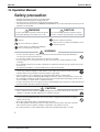
13. Operation Manual
Safety precaution
•
•
•
•
Keep this manual where the operator can easily find them.
Read this manual attentively before starting up the unit.
For safety reason the operator must read the following cautions carefully.
This manual classifies precautions into WARNING and CAUTION. Be sure to follow all precautions below: they are all
important for ensuring safety.
WARNING
CAUTION
If you do not follow these instructions exactly, the unit may
cause property damage, personal injury or loss of life.
If you do not follow these instructions exactly, the unit may
cause minor or moderate property damage or personal injury.
Never do.
Be sure to follow the instructions.
Be sure to earth the air conditioner.
Never cause the air conditioner (including the remote
controller) to get wet.
Never touch the air conditioner (including the
remote controller) with a wet hand.
WARNING
• In order to avoid fire, explosion or injury, do not operate the unit when harmful, among which flammable or
corrosive gases, are detected near the unit.
• It is not good for health to expose your body to the air flow for a long time.
• Do not put a finger, a rod or other objects into the air outlet or inlet. As the fan is rotating at a high speed, it will
cause injury.
• Do not attempt to repair, relocate, modify or reinstall the air conditioner by yourself. Incorrect work will cause electric
shocks, fire etc.
For repairs and reinstallation, consult your Daikin dealer for advice and information.
• The refrigerant used in the air conditioner is safe. Although leaks should not occur, if for some
reason any refrigerant happens to leak into the room, make sure it does not come in contact
with any flame as of gas heaters, kerosene heaters or gas range.
• If the air conditioner is not cooling properly, the refrigerant may be leaking, so call your dealer.
When carrying out repairs accompanying adding refrigerant, check the content of the repairs with our service staff.
• Do not attempt to install the air conditioner by your self. Incorrect work will result in water leakage, electric shocks or
fire. For installation, consult the dealer or a qualified technician.
• In order to avoid electric shock, fire or injury, if you detect any abnormality such as smell of fire, stop the operation and
turn off the breaker. And call your dealer for instructions.
CAUTION
• The air conditioner must be earthed. Incomplete earthing may result in electric shocks. Do not connect the
earth line to a gas pipe, water pipe, lightning rod, or a telephone earth line.
• In order to avoid any quality deterioration, do not use the unit for cooling precision instruments, food, plants,
animals or works of art.
• Never expose little children, plants or animals directly to the air flow.
• Do not place appliances which produce open fire in places exposed to the air flow from the unit or under the
indoor unit. It may cause incomplete combustion or deformation of the unit due to the heat.
• Do not block air inlets nor outlets. Impaired air flow may result in insufficient performance or trouble.
2
Room Air Conditioners D-Series
31
Operation Manual
ED01-505
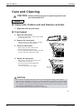
• Do not stand or sit on the outdoor unit. Do not place any object on the unit to avoid injury, do not remove the fan guard.
• Do not place anything under the indoor or outdoor unit that must be kept away from moisture. In certain conditions,
moisture in the air may condense and drip.
• After a long use, check the unit stand and fittings for damage.
• Do not touch the air inlet and aluminum fins of outdoor unit. It may cause injury.
• The appliance is not intended for use by young children or infirm persons without supervision.
• Young children should be supervised to ensure that they do not play with the appliance.
• To avoid oxygen deficiency, ventilate the room sufficiently if equipment with burner is used together with the
air conditioner.
• Before cleaning, be sure to stop the operation, turn the breaker off or pull out the supply cord.
• Do not connect the air conditioner to a power supply different from the one as specified. It may cause trouble or fire.
• Depending on the environment, an earth leakage breaker must be installed. Lack of an earth leakage breaker may
result in electric shocks.
• Arrange the drain hose to ensure smooth drainage. Incomplete draining may cause wetting of the building, furniture
etc.
• Do not operate the air conditioner with wet hands.
• Do not wash the indoor unit with excessive water, only use a slightly wet cloth.
• Do not place things such as vessels containing water or anything else on top of the unit. Water may penetrate into the unit and degrade electrical insulations, resulting in an electric shock.
Installation site.
To install the air conditioner in the following types of environments, consult the dealer.
• Places with an oily ambient or where steam or soot occurs.
• Salty environment such as coastal areas.
• Places where sulfide gas occurs such as hot springs.
• Places where snow may block the outdoor unit.
The drain from the outdoor unit must be discharged to a place of good drainage.
Consider nuisance to your neighbours from noises.
For installation, choose a place as described below.
• A place solid enough to bear the weight of the unit which does not amplify the operation noise or vibration.
• A place from where the air discharged from the outdoor unit or the operation noise will not annoy
your neighbours.
Electrical work.
• For power supply, be sure to use a separate power circuit dedicated to the air conditioner.
System relocation.
• Relocating the air conditioner requires specialized knowledge and skills. Please consult the dealer if relocation is necessary for moving or remodeling.
3
32
Room Air Conditioners D-Series
ED01-505
Operation Manual
Names of parts
Indoor Unit
1
2
3
4
5
10
9
8
6
7
14
13
12
ON/OFF
11
4
Room Air Conditioners D-Series
33
Operation Manual
ED01-505
Outdoor Unit
15
20
17
18
19
16
Indoor Unit
1. Air filter
2. Air purifying filter with
photocatalytic deodorizing function:
• These filters are attached to the inside of the air
filters.
11. Indoor Unit ON/OFF switch: (page 10.)
• Push this switch once to start operation.
Push once again to stop it.
• The operation mode refers to the following
table.
3. Air inlet
Mode
4. Front panel
COOL
5. Panel tab
6. Room temperature sensor:
• It senses the air temperature around the unit.
7. Display
8. Air outlet
9. Flaps (horizontal blades): (page 12.)
10. Louvers (vertical blades):
• The louvers are inside of the air outlet.
(page 13.)
Temperature
setting
22˚C
Air flow
rate
AUTO
• This switch is useful when the remote controller
is missing.
12. Operation lamp (green)
13. TIMER lamp (yellow): (page 15.)
14. Signal receiver:
• It receives signals from the remote controller.
• When the unit receives a signal, you will hear a
short beep.
• Operation start .............beep-beep
• Settings changed..........beep
• Operation stop ..............beeeeep
Outdoor Unit
15. Air inlet: (Back and side)
16. Air outlet
17. Refrigerant piping and inter-unit cable
18. Drain hose
19. Earth terminal:
• It is inside of this cover.
20. Outside air temperature sensor:
• It senses the ambient temperature around the
unit.
Appearance of the outdoor unit may differ from some models.
5
34
Room Air Conditioners D-Series
ED01-505
Operation Manual
Remote Controller
1
ON
2
C
4
ECONO
POWERFUL
ON/OFF
TEMP
5
3
6
9
MODE
SWING
FAN
SILENT MOLD PROOF SENSOR
ON
CANCEL
OFF
7
8
12
14
TIMER
13
11
10
<ARC433A55>
1. Signal transmitter:
• It sends signals to the indoor unit.
2. Display:
• It displays the current settings.
(In this illustration, each section is shown
with all its displays ON for the purpose of
explanation.)
3. POWERFUL button:
POWERFUL operation (page 14.)
4. TEMPERATURE adjustment buttons:
• It changes the temperature setting.
5. ON/OFF button:
• Press this button once to start operation.
Press once again to stop it.
6. MODE selector button:
• It selects the operation mode.
(DRY/COOL/FAN) (page 10.)
7. FAN setting button:
• It selects the air flow rate setting.
8. SWING button:
• Adjusting the Air Flow Direction. (page 12.)
9. ON TIMER button: (page 16.)
10. OFF TIMER button: (page 15.)
11. TIMER Setting button:
• It changes the time setting.
12. TIMER CANCEL button:
• It cancels the timer setting.
13. CLOCK button: (page 9.)
14. RESET button:
• Restart the unit if it freezes.
• Use a thin object to push.
6
Room Air Conditioners D-Series
35
Operation Manual
ED01-505
Preparation Before Operation
To set the batteries
1. Press
with a finger and slide the
front cover to take it off.
Position + and
– correctly!
2
–
+
+
2. Set two dry batteries (AAA).
–
3. Set the front cover as before.
3
1
ATTENTION
About batteries
• When replacing the batteries, use batteries of the same type, and replace the two old batteries
together.
• When the system is not used for a long time, take the batteries out.
• We recommend replacing once a year, although if the remote controller display begins to fade or if
reception deteriorates, please replace with new alkali batteries. Do not use manganese batteries.
• The attached batteries are provided for the initial use of the system.
The usable period of the batteries may be short depending on the manufactured date of the air
conditioner.
7
36
Room Air Conditioners D-Series
ED01-505
Operation Manual
Preparation Before Operation
To operate the remote
controller
• To use the remote controller, aim the transmitter
at the indoor unit. If there is anything to block
signals between the unit and the remote controller, such as a curtain, the unit will not operate.
• Do not drop the remote controller. Do not get it wet.
• The maximum distance for communication is
about 7m.
Receiver
To fix the remote controller
holder on the wall
1. Choose a place from where the signals reach the unit.
2. Fix the holder to a wall, a pillar, etc.
with the screws supplied with the
holder.
3. Place the remote controller in the
remote controller holder.
Remote controller
holder
Set.
• To remove, pull it upwards.
ATTENTION
About remote controller
• Never expose the remote controller to direct sunlight.
• Dust on the signal transmitter or receiver will reduce the sensitivity. Wipe off dust with soft cloth.
• Signal communication may be disabled if an electronic-starter-type fluorescent lamp (such as
inverter-type lamps) is in the room. Consult the shop if that is the case.
• If the remote control signals happen to operate another appliance, move that appliance to somewhere else, or consult the shop.
8
Room Air Conditioners D-Series
37
Operation Manual
ED01-505
To set the clock
1. Press “CLOCK button”.
is displayed.
ON
C
blinks.
2. Press “TIMER setting button” to
set the clock to the present time.
Holding down “
” or “
” button rapidly
increases or decreases the time display.
3. Press “CLOCK button”.
ECONO
POWERFUL
ON/OFF
TEMP
blinks.
Turn the breaker ON
• Turning ON the breaker opens the flap, then
closes it again. (This is a normal procedure.)
MODE
SWING
FAN
SILENT MOLD PROOF SENSOR
2
ON
CANCEL
1, 3
OFF
TIMER
NOTE
Tips for saving energy
• Be careful not to cool the room too much.
Keeping the temperature setting at a moderate level helps save energy.
• Cover windows with a blind or a curtain.
Blocking sunlight and air from outdoors increases the cooling effect.
• Clogged air filters cause inefficient operation and waste energy. Clean them
once in about every two weeks.
Recommended temperature setting
For cooling:26˚C – 28˚C
Please note
• The air conditioner always consumes 15-35 watts of electricity even while it is not operating.
• If you are not going to use the air conditioner for a long period, for example in spring or autumn, turn the breaker
OFF.
• Use the air conditioner in the following conditions.
Mode
COOL
Operating conditions
Outdoor temperature: 20 to 46˚C
Indoor temperature: 18 to 32˚C
Indoor humidity: 80% max.
If operation is continued out of this range
• A safety device may work to stop the operation.
• Condensation may occur on the indoor unit and drip.
DRY
Outdoor temperature: 20 to 46˚C
Indoor temperature: 18 to 32˚C
Indoor humidity: 80% max.
• A safety device may work to stop the operation.
• Condensation may occur on the indoor unit and drip.
• Operation outside this humidity or temperature range may cause a safety device to disable the system.
9
38
Room Air Conditioners D-Series
ED01-505
Operation Manual
DRY · COOL · FAN Operation
The air conditioner operates with the operation mode of your
choice.
From the next time on, the air conditioner will operate with the
same operation mode.
ON
To start operation
C
1. Press “MODE selector button” and
select a operation mode.
• Each pressing of the button advances the
mode setting in sequence.
4
ECONO
: DRY
POWERFUL
ON/OFF
TEMP
2, 3
1
: COOL
: FAN
MODE
FAN
SWING
SILENT MOLD PROOF SENSOR
5
ON
2. Press “ON/OFF button” .
CANCEL
OFF
TIMER
• The OPERATION lamp lights up.
To stop operation
3. Press “ON/OFF button” again.
• Then OPERATION lamp goes off.
To change the temperature setting
4. Press “TEMPERATURE adjustment button”.
DRY or FAN mode
COOL mode
Press “
“
The temperature setting is not variable.
” to raise the temperature and press
” to lower the temperature.
Set to the temperature you like.
C
10
Room Air Conditioners D-Series
39
Operation Manual
ED01-505
To change the air flow rate setting
5. Press “FAN setting button”.
DRY mode
COOL or FAN mode
Five levels of air flow rate setting from “
plus “
” to “
”
” are available.
The air flow rate setting is not variable.
NOTE
Note on DRY operation
• The computer chip works to rid the room of humidity while maintaining the temperature as
much as possible. It automatically controls temperature and fan strength, so manual adjustment of these functions is unavailable.
Note on air flow rate setting
• At smaller air flow rates, the cooling effect is also smaller.
11
40
Room Air Conditioners D-Series
ED01-505
Operation Manual
Adjusting the Air Flow Direction
You can adjust the air flow direction to increase your comfort.
To adjust the horizontal
blades (flaps)
ON
C
1. Press “SWING button”.
is displayed on the LCD and the flaps will
begin to swing.
2. When the flaps have reached the
desired position, press “SWING
button” once more.
The display will go blank.
The flaps will stop moving.
ECONO
POWERFUL
ON/OFF
TEMP
MODE
SWING
FAN
SILENT MOLD PROOF SENSOR
ON
1, 2
CANCEL
OFF
TIMER
12
Room Air Conditioners D-Series
41
Operation Manual
ED01-505
To adjust the vertical blades
(louvers)
Hold the knob and move the louvers.
(You will find a knob on the left-side and the right-side blades.)
• When the unit is installed in the corner of a room,
the direction of the louvers should be facing away
from the wall.
If they face the wall, the wall will block off the wind,
causing the cooling efficiency to drop.
Notes on flaps and louvers angles
• When “SWING button” is selected, the
flaps swinging range depends on the
operation mode. (See the figure.)
ATTENTION
• Always use a remote controller to adjust the
flaps angle. If you attempt to move it forcibly
with hand when it is swinging, the
mechanism may be broken.
• Be careful when adjusting the louvers.
Inside the air outlet, a fan is rotating at a high
speed.
In DRY mode or COOL mode
When stop operation
10˚
Upper limit
50˚
Lower limit
In FAN mode
When stop operation 5˚
Upper limit
70˚
Lower limit
13
42
Room Air Conditioners D-Series
ED01-505
Operation Manual
POWERFUL Operation
POWERFUL operation quickly maximizes the cooling effect in
any operation mode. You can get the maximum capacity .
To start POWERFUL
operation
ON
C
1. Press “POWERFUL button”.
• POWERFUL operation ends in 20 minutes. Then
the system automatically operates again with the
settings which were used before POWERFUL
operation.
• When using POWERFUL operation, there
are some functions which are not available.
•
“
ECONO
POWERFUL
ON/OFF
TEMP
1, 2
” is displayed on the LCD.
To cancel POWERFUL
operation
2. Press “POWERFUL button” again.
• “
” disappears from the LCD.
MODE
SWING
FAN
SILENT MOLD PROOF SENSOR
ON
CANCEL
OFF
TIMER
NOTE
Notes on POWERFUL operation
• POWERFUL Operation can only be set when the unit is running. Pressing the operation
stop button causes the settings to be canceled, and the“ ”disappears from the LCD.
• In COOL mode
The air flow rate is fixed to the maximum setting.
The temperature and air flow settings are not variable.
• In DRY mode
The temperature setting is lowered by 2.5˚C and the air flow rate is slightly increased.
• In FAN mode
The air flow rate is fixed to the maximum setting.
14
Room Air Conditioners D-Series
43
Operation Manual
ED01-505
TIMER Operation
Timer functions are useful for automatically switching the air
conditioner on or off at night or in the morning. You can also
use OFF TIMER and ON TIMER in combination.
To use OFF TIMER operation
ON
C
• Check that the clock is correct.
If not, set the clock to the present time.
(page 9.)
1. Press “OFF TIMER button”.
ECONO
POWERFUL
ON/OFF
TEMP
is displayed.
blinks.
2. Press “TIMER Setting button” until
the time setting reaches the point
you like.
• Every pressing of either button increases or
decreases the time setting by 10 minutes.
Holding down either button changes the setting rapidly.
MODE
SWING
FAN
SILENT MOLD PROOF SENSOR
ON
CANCEL
2
4
OFF
TIMER
1, 3
3. Press “OFF TIMER button” again.
• The TIMER lamp lights up.
To cancel the OFF TIMER operation
4. Press “CANCEL button”.
• The TIMER lamp goes off.
NOTE
• When TIMER is set, the present time is not displayed.
• Once you set ON, OFF TIMER, the time setting is kept in the memory. (The memory is canceled when
remote controller batteries are replaced.)
• When operating the unit via the ON/OFF Timer, the actual length of operation may vary from the time
entered by the user. (Maximum approx. 10 minutes)
NIGHT SET MODE
When the OFF TIMER is set, the air conditioner automatically adjusts the temperature setting (0.5˚C
up in COOL) to prevent excessive cooling for your pleasant sleep.
15
44
Room Air Conditioners D-Series
ED01-505
Operation Manual
TIMER Operation
To use ON TIMER operation
• Check that the clock is correct. If not, set the
clock to the present time (page 9.).
1. Press “ON TIMER button”.
ON
is displayed.
C
blinks.
2. Press “TIMER Setting button” until
the time setting reaches the point
you like.
• Every pressing of either button increases or
decreases the time setting by 10 minutes.
Holding down either button changes the setting rapidly.
3. Press “ON TIMER button” again.
• The TIMER lamp lights up.
ECONO
POWERFUL
ON/OFF
TEMP
MODE
SWING
FAN
SILENT MOLD PROOF SENSOR
1, 3
ON
CANCEL
4
OFF
To cancel ON TIMER
operation
TIMER
2
4. Press “CANCEL button”.
• The TIMER lamp goes off.
To combine ON TIMER and OFF TIMER
• A sample setting for combining the two timers is shown below.
Display
(Example)
Present time: 11:00 p.m.
(The unit operating)
OFF TIMER at 0:00 a.m.
ON TIMER at 7:00 a.m.
Combined
ATTENTION
In the following cases, set the timer again.
• After a breaker has turned OFF.
• After a power failure.
• After replacing batteries in the remote controller.
16
Room Air Conditioners D-Series
45
Operation Manual
ED01-505
Care and Cleaning
CAUTION
Before cleaning, be sure to stop the operation and
turn the breaker OFF.
Units
Indoor unit, Outdoor unit and Remote controller
1. Wipe them with dry soft cloth.
Front panel
1. Open the front panel.
• Hold the panel by the tabs on the two sides and lift
it unitl it stops with a click.
2. Remove the front panel.
• Lift the front panel up, slide it slightly to the right,
and remove it from the horizontal axle.
3. Clean the front panel.
• Wipe it with a soft cloth soaked in water.
• Only neutral detergent may be used.
• In case of washing the panel with water, dry it with
cloth, dry it up in the shade after washing.
4. Attach the front panel.
• Set the 2 keys of the front panel into the slots
and push them in all the way.
• Close the front panel slowly and push the
panel at the 3 points.
(1 on each sides and 1 in the middle.)
Fit the key
into the slot.
CAUTION
•
•
•
•
Don’t touch the metal parts of the indoor unit. If you touch those parts, this may cause an injury.
When removing or attaching the front panel, use a robust and stable stool and watch your steps carefully.
When removing or attaching the front panel, support the panel securely with hand to prevent it from falling.
For cleaning, do not use hot water above 40˚C, benzine, gasoline, thinner, nor other volatile oils, polishing compound, scrubbing brushes, nor other hand stuff.
• After cleaning, make sure that the front panel is securely fixed.
17
46
Room Air Conditioners D-Series
ED01-505
Operation Manual
Filters
1. Open the front panel. (page 17.)
2. Pull out the air filters.
• Push a little upwards the tab at the center of each air
filter, then pull it down.
3. Take off the air purifying filter with
photocatalytic deodorizing function.
• Hold the recessed parts of the frame and unhook
the four claws.
4. Clean or replace each filter.
Air purifying filter
with photocatalytic
deodorizing function Air filter
See figure.
Filter frame
Tab
5. Set the air filter and the air purifying
filter with photocatalytic deodorizing function
as they were and close the front panel.
Push
• Insert claws of the filters into slots of the front panel. Close
the front panel slowly and push the panel at the 3 points. (1
on each sides and 1 in the middle.)
Air Filter
1. Wash the air filters with water or clean them with
vacuum cleaner.
• If the dust does not come off easily, wash them with neutral detergent
thinned with lukewarm water, then dry them up in the shade.
• It is recommended to clean the air filters every two weeks.
Air purifying filter with photocatalytic
deodorizing function (gray)
The Air purifying filter with photocatalytic deodorizing function can be
renewed by washing it with water once every 6 months. We recommend
replacing it once every 3 years.
[ Maintenance ]
1.
2.
3.
4.
5.
Remove dust with a vacuum cleaner and wash lightly with water.
If it is very dirty, soak it for 10 to 15 minutes in water mixed with a neutral cleaning detergent.
Do not remove filter from frame when washing with water.
After washing, shake off remaining water and dry in the shade.
Since the material is made out of paper, do not wring out the filter when removing water from it.
[ Replacement]
1. Remove the tabs on the filter frame and replace with a new filter.
• Dispose of the old filter as flammable waste.
18
Room Air Conditioners D-Series
47
Operation Manual
ED01-505
NOTE
• Operation with dirty filters:
(1) cannot deodorize the air.
(2) cannot clean the air.
(3) results in poor cooling.
(4) may cause odour.
• To order air purifying filter with photocatalytic deodorizing function contact to the service shop there
you bought the air conditioner.
• Dispose of old filters as flammable waste.
Item
Air purifying filter with photocatalytic deodorizing
function. (without frame) 1 set
Part No.
KAF970A44
Check
Check that the base, stand and other fittings of the outdoor unit are not decayed or corroded.
Check that nothing blocks the air inlets and the outlets of the indoor unit and the outdoor unit.
Check that the drain comes smoothly out of the drain hose during COOL or DRY operation.
• If no drain water is seen, water may be leaking from the indoor unit. Stop operation and consult the service shop if this is the case.
Before a long idle period
1. Operate the “Fan only” for several hours on a fine day to dry out the
inside.
• Press “MODE selector button”and select “Fan”operation.
• Press “ON/OFF button”and start operation.
2. Clean the air filters and set them again.
3. Take out batteries from the remote controller.
4. Turn OFF the breaker for the room air conditioner.
19
48
Room Air Conditioners D-Series
ED01-505
Operation Manual
Trouble Shooting
These cases are not troubles.
The following cases are not air conditioner troubles but have some reasons. You may just continue using it.
Case
Explanation
Operation does not start soon.
• When ON/OFF button was
pressed soon after
operation was stopped.
• When the mode was
reselected.
• This is to protect the air conditioner.
You should wait for about 3 minutes.
The outdoor unit emits water or
steam.
In COOL or DRY mode
• Moisture in the air condenses into water on the cool
surface of outdoor unit piping and drips.
Mists come out of the indoor
unit.
This happens when the air in the room is cooled into mist by
the cold air flow during cooling operation.
The indoor unit gives out odour. This happens when smells of the room, furniture, or
cigarettes are absorbed into the unit and discharged with the
air flow.
(If this happens, we recommend you to have the indoor unit
washed by a technician. Consult the service shop where you
bought the air conditioner.)
The outdoor fan rotates while
the air conditioner is not in
operation.
After operation is stopped:
• The outdoor fan continues rotating for another 60
seconds for system protection.
While the air conditioner is not in operation:
• When the outdoor temperature is very high, the outdoor
fan starts rotating for system protection.
The operation stopped
suddenly.
(OPERATION lamp is on.)
For system protection, the air conditioner may stop
operating on a sudden large voltage fluctuation.
It automatically resumes operation in about 3 minutes.
20
Room Air Conditioners D-Series
49
Operation Manual
ED01-505
Check again.
Please check again before calling a repair person.
Case
The air conditioner does not
operate.
(OPERATION lamp is off.)
Check
• Hasn’t a breaker turned OFF or a fuse blown?
• Isn’t it a power failure?
• Are batteries set in the remote controller?
• Is the timer setting correct?
Cooling effect is poor.
• Are the air filters clean?
• Is there anything to block the air inlet or the outlet of the
indoor and the outdoor units?
• Is the temperature setting appropriate?
• Are the windows and doors closed?
• Are the air flow rate and the air direction set appropriately?
Operation stops suddenly.
(OPERATION lamp flashes.)
• Are the air filters clean?
An abnormal functioning
happens during operation.
• The air conditioner may malfunction with lightning or radio
waves. Turn the breaker OFF, turn it ON again and try
operating the air conditioner with the remote controller.
• Is there anything to block the air inlet or the outlet of the
indoor and the outdoor units?
Clean the air filters or take all obstacles away and turn the
breaker OFF. Then turn it ON again and try operating the air
conditioner with the remote controller. If the lamp still flashes,
call the service shop where you bought the air conditioner.
21
50
Room Air Conditioners D-Series
ED01-505
Operation Manual
Call the service shop immediately.
WARNING
When an abnormality (such as a burning smell) occurs, stop operation and turn the breaker OFF.
Continued operation in an abnormal condition may result in troubles, electric shocks or fire.
Consult the service shop where you bought the air conditioner.
Do not attempt to repair or modify the air conditioner by yourself.
Incorrect work may result in electric shocks or fire.
Consult the service shop where you bought the air conditioner.
If one of the following symptoms takes place, call the service shop immediately.
The power cord is abnormally hot or damaged.
An abnormal sound is heard during operation.
The safety breaker, a fuse, or the earth leakage breaker
cuts off the operation frequently.
A switch or a button often fails to work properly.
There is a burning smell.
Water leaks from the indoor unit.
After a power failure
The air conditioner automatically resumes
operation in about 3 minutes. You should just
wait for a while.
Turn the breaker
OFF and call the
service shop.
Lightning
If lightning may strike the neighbouring area,
stop operation and turn the breaker OFF for
system protection.
We recommend periodical maintenance.
In certain operating conditions, the inside of the air conditioner may get foul after several seasons of
use, resulting in poor performance. It is recommended to have periodical maintenance by a specialist
aside from regular cleaning by the user. For specialist maintenance, contact the service shop where
you bought the air conditioner.
The maintenance cost must be born by the user.
22
3P153868-2B
Room Air Conditioners D-Series
51
Optional Accessories
ED01-505
14. Optional Accessories
14.1 Option List
Option Name
Notes:
52
Kit Name
Applicable
Model
1
Centralized control board-up to 5 rooms +1
KRC72
Indoor Unit
2
Wiring adaptor for time clock/remote control +2
(Normal open pulse contact / Normal open contact)
KRP413A1S
Indoor Unit
3
Air Purifying Filter with Photocatalytic Deodorizing Function
KAF970A44
Indoor Unit
4
Remote controller loss prevention with the chain
KKF917A4
Indoor Unit
5
Drain Plug
KKP937A4
Outdoor Unit
6
Air Direction Adjustment Grille
KPW937A4
Outdoor Unit
+1 Wiring adaptor is also required for each indoor unit.
+2 Wiring adaptor ; supplied by DAIKIN. Time clock and other devices ; obtained locally.
Room Air Conditioners D-Series
ED01-505
Optional Accessories
14.2 Installation Manual
14.2.1 KRP413A1S
Room Air Conditioners D-Series
53
Optional Accessories
ED01-505
Installation
This product is available in two types. The KRP413A1S
installation within the indoor unit.
is for installation in a case independent of the indoor unit, and the KRP413A1
1. KRP413A1S
1
is for
3. Attaching Adaptor Case Assy (for KRP413A1S)
Installation diagram
1
Adaptor case
Indoor unit PCB
Using the screws (to mount on a wall, etc.)
● Use the 3 supplied screws to attach the case assy .
Adopter case
S21
Indoor unit
Relay harness
2
Local inter-unit
power cord, etc.
Install the adaptor case assy as close to the indoor unit as possible.
� Removing case front
Case front
Components
� Adaptor case assy
(Adaptor (PCB) is attached in the adaptor case.)
� Relay harness (approx. 0.8 m)
Screw
Adaptor PCB
Screw cover
� Accessories
• Tie-wrap (4 pcs.)
• Velcro for attaching to the indoor unit (2 sets)
• Screws for attaching the adaptor case (4 pcs.)
• Screws for attaching to the wall (3 pcs.)
Remove the screw cover, one of the screws
and then the case front.
� Attach the case back to the surface by
tightening the screws through the screw
holes (one round hole, two long holes).
� After connecting the cables (refer to the following sections), replace the
case front. Be careful not to damage the harness in the case.
Press in so that the prong catches
the case back.
� Installation manual
Wiring
2. KRP413A1
For this type, install the adaptor PCB within the indoor unit. The method of
installation and connection vary depending on the model of the air
conditioner. See your air conditioner installation manual for details.
1
Screw
Screw cover
Components
� Adaptor PCB
� Relay harness (approx. 0.25 m)
2
Using Velcro (to attach on the indoor unit)
● Attach the adaptor case with the supplied Velcro.
� Remove the case front (as for mounting on a wall).
� After connecting the cables (see the following sections), replace the
case front. It can be screwed to the case back from the rear with the
four supplied screws.
Be careful not to damage the harness in the case.
� Stick one end of the Velcro to the rear side of the case back, and stick
the other end to the indoor unit with the same space between them.
� Installation manual
Velcro male
(female)
Velcro female
(male)
Indoor unit
To prevent the adaptor case assy from falling, do not use the Velcro for
attaching it to a wall or other surface.
54
Room Air Conditioners D-Series
ED01-505
Room Air Conditioners D-Series
Optional Accessories
55
Optional Accessories
56
ED01-505
Room Air Conditioners D-Series
ED01-505
Optional Accessories
14.2.2 KPW937A4
Q Before Installation
Checking the parts
Check the following parts
Name
Louver
Installation manual
Shape
Quantity
With 4 screws
1piece
1piece
Q Installation Procedure
Selection of Installation Location
Use when installing in a location that meets the following conditions.
zWhen installing near the border to a neighbor's house
zIf exhaust blows directly on passers-by because outdoor unit is installed facing a road.
zChanging the fan direction of the outdoor unit to prevent it blowing directly on shrubbery, etc.
Installation of Louver
zInstallation is possible in the four directions:
upward, downward, rightward, and leftward.
zThe installation screws are attached to the louver.
zFirst temporarily attach the louver with 4 screws,
then check that the angle is correct, and finally
tighten the screws fully.
Prepared hole
pitch 435mm
Fan partition
Part A
(see figure below)
Prepared hole
pitch 435mm
Fan partition
CAUTION
1.Install so that a short circuit is prevented.
2.For the use in snowy regions, avoid installation
with the air outlet facing upward. Install so that
the air outlet faces leftward, rightward, or downward.
Snow accumulates in the air outlet of the outdoor
unit, causing malfunction of the main body of the
outdoor unit.
3.Be advised that if the fan direction is up,
dead leaves and other foreign matter
easily accumulates in the exhaust vent.
The prepared hole is in between the grating
of the grille. Part A (prepared hole) cross
section (the shape of either a or b)
a) Grille grating
Prepared hole
b) Grille grating
Prepared hole
4P104499-1
Room Air Conditioners D-Series
57
ED 01-505
Printed in Japan 05/2005 B AK