1
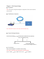
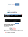
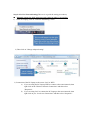
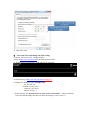
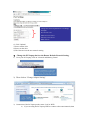
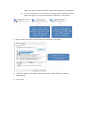
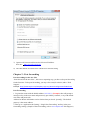
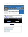
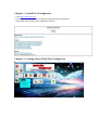
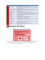
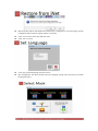
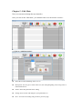
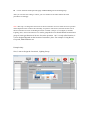
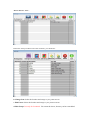
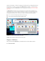
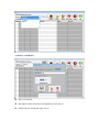
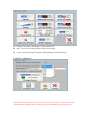
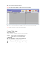
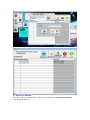
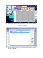
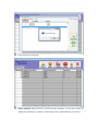
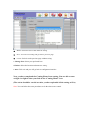
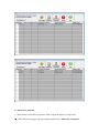
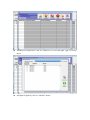
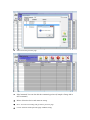
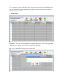
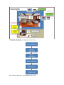
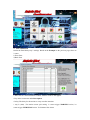
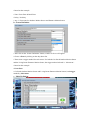
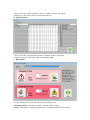
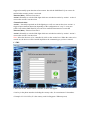
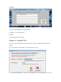
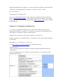
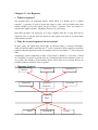
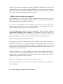
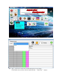
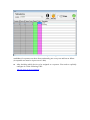
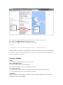
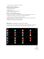
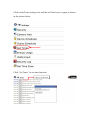
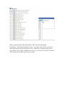
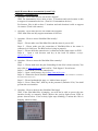
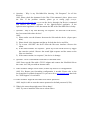
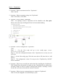
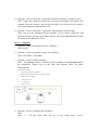
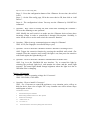
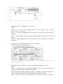
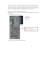
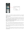
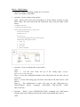
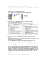
iNet Configurator Manual Part I: Network Setup Chapter 1 - iNet Network Setup(Local WiFi Access) Chapter 2 - Port Forwarding(WiFi/3G Remote Access) Part II: User Interface and System Design/Redesign Chapter 3 - Install iNet Configurator Chapter 4 - Getting Started With iNet Configurator Chapter 5 - Edit Main Chapter 6 - Edit Device Chapter 7 - Edit Scene Chapter 8 - Edit Conditions Chapter 9 - Set Line Break Chapter 10 - Security Chapter 11 - Upload To iNet Part III: Htm Page Chapter 12 - Fill up Device ID into iNet(ipconfig.htm) Chapter 13 - Set Repeater Notes For Installer Part IV: FAQ Introduction Welcome to the world of wireless communication. We are pleased that you have chosen the Anjels iNet. iNet Configurator is a software for you to personalize your iNet. iNet Configurator allows you to Create/Edit/Delete the data structure, icons, scene control and extra to enhance your lifestyle. The user guide will go through the whole process with a sample project for better understanding. Chapter 1 - iNet Network Setup Introduction Note: This manual will guides through the configuration of iNet network with the router network. iNet Hardware Connection Note: iNet MUST connect to the router with LAN cable only. Network Checking Flowchart Check Network Setting Is Subnet Mask and Default Gateway(Router) same as iNet Default Setting Yes Ready For Test No Need to Setting the iNet (refer to the iNet Setup Procedures ) Network Setup Step 1: On the Laptop/PC - Check The Network setting Note: This is to check the network parameters of the local router (1) Go to “Start” Type “cmd” and click search Select cmd.exe (2) Type ipconfig (3) Press Enter (4) Check the Subnet Mask and Default Gateway (5) Compared with iNet Default Setting Default Setting for iNet: a.IP Address: 192.168.1.81 b.Subnet Mask: 255.255.255.0 c. Default Gateway: 192.168.1.1 If the parameters are same, we do not need to change any setting. It can be used for testing or uploading data directly. If the parameters are different, then we need to change the setting of iNet(Refer to step2) to communicate to local network(Router). Step 2: iNet New Network Setting(This one is to guide the setting procedures) Manually change the PC/Laptop network setting in order to access iNet. 1) At the PC/Laptop, click on "Network and Sharing Center" 2) Then click on "Change Adapter Setting" 3) Connection of the PC/Laptop to the router: LAN or WIFI a) If you are using the PC/Laptop WIFI to connect to the router/network, then right click on the "Wireless Network Connection" and then select "Properties". b) If you are using LAN to connect the PC/Laptop to the router/network, then right click on you “Local Area Connection” and then select “Properties”. 4) Then, double click on the "Internet Protocol Version 4 (TCP/IPV4)” 5) Check the “Use the following IP address” 6) Key in the information as below, IP address: 192.168.1.100 Subnet Mask: 255.255.255.0 Default Gateway: 192.168.1.1 7) Then click “OK” Access the iNet and change the iNet setting 1) Open a web browser. (IE / Google Chrome) 2) Key in http://192.168.1.81:8181(by default) and press Enter 3) You should see a black image with "All ON" & "All OFF" 4) After that, key in http://192.168.1.81:8181/ipconfig.cgi 5) Change the setting as below, (Example only) IP: 192.168.2.81 MASK: 255.255.255.0 Gateway: 192.168.2.1 DNS: 192.168.2.1 (In this example, the “Default Gateway of the router is 192.168.2.1”, which is different from iNet default setting, therefore we make the changes of iNet as above.) Change the network parameters accordingly Example: IP=192.168.2.81 Mask=255.255.255.0 Gateway=192.168.2.1 DNS=8.8.8.8 6) Click "Submit". 7) Power off the iNet. 8) Power on the iNet. 9) The iNet now has the new network setting. Change the PC/Laptop back to the Router Default Network Setting. 1) Go to your PC/Laptop, click on "Network and Sharing Center" 2) Then click on "Change Adapter Setting" 3) Connection of the PC/Laptop to the router: LAN or WIFI a) If you are using the PC/Laptop WIFI to connect to the router/network, then b) right click on the "Wireless Network Connection" and then go "Properties". If you are using LAN to connect the PC/Laptop to the router/network, then right click on you “Local Area Connection” and then go “Properties”. 4) Then, double click on the "Internet Protocol Version 4 (TCP/IPV4)” 5) Check the “Obtain an IP address automatically.”& “Obtain DNS server address automatically” 6) Click “OK”. 7) Open a web browser and browse the iNet new IP address New one: http://192.168.2.81:8181 8) The iNet shall be accessible now with the new network setting. Chapter 2 - Port forwarding Port forwarding for the new iNet. “Port forward for the new iNet” , this is not a repeating step, you have to do port forwarding for the first time. To do port forwarding, you may refer to Anjels website, under “Tech Support”. Example: http://www.anjels.com/template.jsp?p=my/RouterConfigurationforiNet.html Port Forwarding 1. Log into the router with the default address 192.168.1.1 (Example) then will prompt a message to key in the user name and password, (provided by customer, or try with default user name and password). Address for Router information can be obtain when you check “ipconfig”. The default gateway is the router address. 2. Then go to “Application & Gaming”, “Single Port Forwarding” and key in the port forwarding settings, (Sample of Port Forwarding, refer to www.anjels.com Tech Support.) HTTP Server, Public Port = 8181, Local Port = 8181 FTP Server, Public Port = 8121, Local Port = 21 Telnet Server, Public Port =8123, Local Port = 23 4) The new iNet is connected and ready for uploading. Make sure the new iNet is connected, and you are able to connect to the webpage 192.168.1.81:8181 locally as shown: Make sure access the i-Net with another network, example: Smart phone 3G to access the i-Net with address http://inet.anjels.com : Key in iNet serial no. & Password Chapter 3 - Install iNet Configurator 1. Visit http://inet.anjels.com 2. Click on Mini-iNet cum iNet Configurator Setup Program (for Windows) 3. Download and install the iNet Configurator software Chapter 4 - Getting Started With iNet Configurator After you click on “Delete All Data” icon, a window as above will appear. You have to key in the word “delete” and click “OK”, in order to delete all the data in the Configurator. Click “Cancel” to go back to previous page. After click on “Select IP” button, window as above will appear. Key in the iNet IP address. Click “Cancel” to go back to previous page. iNet Configurator will search for upgrade through internet automatically Upgrade the iNet to a newer version. You may upgrade from a version to the same version with no ill effect. This option is provided in case of any error during upgrading and the process is incomplete. Once upgraded, you cannot downgrade. Certain upgrade may cause the iNet to reboot but this will be done automatically if necessary. Note:iNet Configurator version and iNet version is not necessary to be the same. Data from iNet will be download and restored to the Configurator in your PC/Laptop. All the Configurator data on the PC/Laptop will be overwritten. Click “Yes” to start restore the data from iNet. Click “No” to cancel. “Tick” the preferred language and click “Save”. iNet Configurator will shut off itself. The new language setting will work when you launch the program again. After you click on A/B, you should be able to see the different shapes as below: Choose the preferred mask and go to previous page by clicking on Exit. “ Pick Picture”Select the picture that you want to create as an icon. The picture to be used as an icon will shown at “New icon is shown here”. Give a name for the new icon and click “Save”. “Cancel” is to cancel and go back to previous page. Chapter 5 - Edit Main Now, we can start to design the user interface. Once you click on the “Edit Main”, you should be able to see the window as below : a. Click on “Add Description” Select the Location ID(Range from 0 to 12) Description: You can give a name of the icon, For example lighting, fans, living room or master bedroom etc. Footer: Select the preferred footer setting. Change Icon: Choose and change to your preferred icon. Save:Save the new setting and go back to previous page Cancel: Go back to the previous page without adding a new location/group. After you save the new setting or cancel, you can continue to do others follow the same procedures accordingly. Note: This step is to design the main icons in the user interface. You can select the icon’s position which depends on the Location ID. Normally, we prefer to start from 0, because the first row in the user interface are some controlling shortcuts or called “ Groups”. For example, it includes Lighting, Fans, Aircon and Curtain. It is used to group the devices from different location into a group of same type/function of devices for easier operation. 1 to 12 is only called location, it is to be designed depends on the location of customer’s place. For example: Living Room, Car porch, Mater Bedroom etc. Example Only: Now, I want to design the Location 0, Lighting Group After I click on ‘ Save ’ : Follow the same procedures to do other locations, you should see : b. Change Icon: Select the location and change to your preferred icon. c. Edit Footer: Select the location and change to your preferred footer. d. Edit Group: It is only for Location 0. You cannot do it now, because you have not added any device to location 1-12 and it is an empty one. In other words, you cannot pick any device from location 1-12. Hence, we need to do the Edit device for location 1-12 to form a device list firstly, then go back to Edit main to do the edit group for location 0.(refer to next chapter edit device) e. Add Function: It includes some special functions, for example: Device Schedules, Set Timer, Energy Usage, Security and Scene Schedules. Actually, it is an default settings inside the setting of main menu. Here, it allows you to make it a shortcut for easier operation. Save:Save the new setting and go back to previous page. Cancel: Go back to the previous page without saving. f. Delete: Select the location and delete the setting. g. Exit: Click exit and you will go back to previous page. Chapter 6 - Edit Device Once you click on the “Edit Device”, you should be able to see the window as below : Select the location a. Click on “Add Device” Select Location ID Description: Name of the devices(It depends on your choice) Change Device: Change the types of icon Change Icon: Choose and change to your preferred icon. Save:Save the new setting and go back to previous page Cancel: Go back to the previous page without adding a new location/group. b. Click on “Add Sensor” Note: The location for sensor is only from 13-15, device ID is from 1-16. But location 13-15 is not means they should be there. Actually, they can be added to any location from 1-12. c. Click on “Add Siren” Note: The location for siren is only 16, Device ID: 1- 4 d. Delete: Select the location and delete the setting. e. Exit: Click exit and you will go back to previous page. *Edit Group(It need to be done in Edit Main) Edit main-Select Location 0(any one of lighting, fans, aircon or curtain) Click “Edit Group” - Click “Add device” Now, you can pick any device from different location into a same type/function group for easier operation. Select the device and Click “Add One” Note: You can continue to add device and click Exit to leave this page. Click on “Save” to confirm your settings or Click Cancel to leave without saving. Note: Do the rest location 0 follow the same procedures. Chapter 7 - Edit Scene What is Edit Scene? Scenes control –By one click to activate a series of activities. Example:Leaving Home - Off all the lights & aircon. Coming Home - On all the lights & aircon a. Add Scene Make a Description: Coming Home(Example only) Change Icon: Select your preferred Icon Save:Save the new setting and go back to previous page. Cancel: Go back to the previous page without saving. b. Edit Scene Command Select One Scene and Click on “Edit Scene Command” (Coming Home Example) You should be able to see: Add device and Add sensor: Here, we can select a lot of devices to be controlled in this series of activities. Select the light and action you want to control when coming home(turn on lights) and click on “Add One” Click Exit to leave this page Edit Command: Select the device and Click Edit Command, you also have chance to change the command, for example: On/Off, Open/Close, Enable/Disable your devices. Delete: Select the device and delete the setting. Save:Save the new setting and go back to previous page. Cancel: Go back to the previous page without saving. c. Change Icon: Select your preferred Icon d. Delete: Select the location and delete the setting. e. Exit: Click exit and you will go back to configurator interface. Now, you have completed the Coming Home Scene setting. You are able to turn on light 1 to light 4 when you click on the “Coming Home” icon. (The action should be carried out after you have uploaded all the setting to iNet) Note: You can follow the same procedures to do the other scene control. Chapter 8 - Edit Conditions What is Edit Condition? Normally, it is for sensor(i-sensor/i-Guard) to activate a series of activities when the sensor was triggered by movement. Example:Sensor turns on light when it detect movement(You must ensure your system has some sensors. If not, this Condition is not need to be configured) Here, my living room has a motion sensor. I want to turn on light1 and light2 when sensor detect movement in living room. When there is no motion detected, turn off the lights. Let’s start this chapter: a. Add Trigger Select the motion sensor in living room Trigger Upon: 2 types 1. Motion/Bright/Open (It means the sensor is triggered by motion,then it will activate some activities.) 2. No Motion/Dark/Close (It means the sensor detect no motion,then it will activate some activities.) Save:Save the new setting and go back to previous page. b. Edit Scene Command 1. When motion sensor detect movement: Turn on light1 & light2 in Living Room Select the sensor (trigger type upon motion) and Click on “Edit Scene Command” Add Device & Add Sensor: Click on “Add device” to select the light1, light 2 in Living Room Add light1 & light2 by click on “Add One” button Exit: Go back to previous page. Edit Command: You can also edit the command types here.(Example: Change ON to OFF command ) Delete: Select the device and delete the setting. Save:Save the new setting and go back to previous page. Cancel: Go back to the previous page without saving. Note: Add sensor is same as add device here. It means we are not only can On/Off lights, but also can control other sensors(Enable/Disable) when one sensor triggered by movement to activate a series of activities. c. Add EzSwitch Sometimes, we want to use EzSwitch to control some devices for easier operation. Therefore, we need to create Scenes Control for Ezswitch. Click on Add EzSwitch and select a location for it Click on ‘ Save ’ to save new setting ID of EzSwitch Scene: 0106(Example) This ID must be write down, because we will do the configuration for EzSwitch in htm page for controlling this Scene.(Refer to EzSwitch Configuration Manual) Edit Scene Command: Refer to add trigger procedures(Here, we use EzSwitch to turn on light 3& light4 in Living Room) Click on “Save” to save new setting Note: The EzSwitch has 4 buttons, which one is for controlling light3 & light4 is depending on your EzSwitch configuration. Remember to write down the ID of the Scene for EzSwitch (Please refer to EzSwitch Configuration Manual.) d. Delete: Select the location and delete the setting. e. Exit: Click exit and you will go back to configurator interface. Chapter 9 - Set Line Break Click on “LineBreak” on Configurator User Interface We can preview the Main menu we have designed before Click the Green Color line to set the line break Exit: Go to previous page with saving Chapter 10 - Security Notes: • This user manual covers only the Security System configuration. • Both user manuals are available on http://inet.anjels.com • ALL the Devices/Sensors that used in Security System have to be pre-configured location IDs & device IDs. Security Security System -Configuration Flow Chart Click on “Security”, you should be able to see: a. Zone Definition Define the Zone/Delay/Any 2 settings. Based on the Example on the previous page, there are 2 zones: 1)Front Zone 2)Back Zone • After click on “Zone Definition” button, window as above will appear. • Key in the zone name under Description. • Delay–The delay for the actions to carry out after intrusion. • Any 2 (mins) –For motion sensor pair setting. 1st sensor trigger WARNING action, 2nd sensor trigger INTRUSION action. To eliminate false alarm. • Based on the example: • Zone -Front Zone & Back Zone. • Delay –No delay. • Any 2 –Front zone for Outdoor Motion Sensor and Entrance Motion Sensor b. Sensor Definition • After click on the “Sensor Definition” button, window as above will appear. • Choose a Zone by clicking on the drop down list. • Then select a trigger method for each sensor. For both the Car Porch Outdoor Motion Sensor and the Living Room Entrance Motion Sensor, the trigger method selected is ‘ Movement ’. • Based on the example: • Front Zone: • Car Porch Outdoor Motion Sensor and Living Room Entrance Motion Sensor, both trigger method by Movement. c. Mode Definition • After click on the “Mode Definition” button, a window as above will appear. • Then key in a descriptive name for each mode and Exit. d. Zone Selection • After click on the “Zone Selection” button, a window as above will appear. • Tick the zones to be associated with a corresponding mode. e. Edit Action • Choose the Mode to be edit with actions by the drop down list. • Warning Action: (Only work with Any 2 motion sensors setting) Action 1 - Normally to switch on a light. Action 1 is triggered when the first sensor is triggered, normally upon detection of movement. Just tick the SMS/Email if you want to be notified when warning action is activated. Timeout (Mins) –Timeout for Action 1. Action 2-Normally to switch off the light which are switched on earlier by Action 1. Action 2 occurs after Action 1 has timed out. • Intrusion Action: Action 1 - Normally topswitch on all the lightings as well as to turn on the siren. Action 1 is triggered upon intrusion detection depending on the configuration as "Any 2" or any one sensor. Just tick the SMS/Email if you want to be notified when intrusion is activated Timeout (Mins) –Timeout for Action 1. Action 2-Normally to switch off the light which are switched on earlier by Action 1.Action 2 occurs after Action 1 has timed out. Note: Select the Devices to be controlled by click on the Action Icon. When the action to be carried out, the devices will be On/Off depends on the command types you have selected. f. SMS • After click on the “SMS” button, a window as above will appear. • Just key in the phone numbers including the country code, for a maximum of 10 numbers. • Example: 65 1234 5678 (65 is the country code for Singapore. Without spaces) g. Email • After click on the “Email” button, a window as above will appear. • Just key in a maximum of 10 email addresses. • Example: ******@hotmail.com h. Exit • Exit and back to previous page. Chapter 11 - Upload To iNet When you come to this chapter, that means you have already completed all the design and settings. Select IP(This is the IP address of iNet) and click on “Save” Note: iNet default IP address is 192.168.1.81 Port Number is 8181. But sometimes we need to change the default IP(refer to chapter 1), we must select the New IP here to allow the iNet to communicate with Configurator.(For example: we select ip: 192.168.2.1 here) Upload to iNet Click on the Icon “ Upload to iNet ”. Now, we can upload all the settings to iNet. After that, we should be able to see the main menu at: http://192.168.1.81:8181 (The ip address depends on your setting. If you change the ip before, you need to use the new one(Example http:192.168.2.1:8181); If not, it should be the default IP) Chapter 12 - Fill up Device ID Into iNet Note: After we uploaded the settings into iNet, we can start to fill up each device into iNet(Topswitch, Dimmer, Converter etc.). Actually, we can prepare it for installation in our office and give each product a sticker to indicate the ID. Example: 01 01 The first 01 is the location 1 and the 01 is the device 1. Example: Location 1 is Living Hall, device 1 is a dimmer, so 0101 is the i-Dimmer installed at Living hall. Max location = 12 Max devices = 12x16=192 Go to http://192.168.1.81:8181/config.htm You should be able to see: To add the devices, 1. Key in the location and device number according to the POR form/Sticker, then press “ADD Device”. 2. After you add the device, try “ON Device” and “OFF Device”, you will see the actual feedback from the device. Chapter 13 - Set Repeater 1. What is repeater? Our products have an important feature which allow it to double up as a “signal repeater”. A repeater is used to repeat the signal so that a device further away that cannot reliably receive the signal, can get it from a repeater. Users can choose to activate this“signal repeater” capability whenever it is necessary. Note that repeaters can repeat up to 3 hops. Signals after the 3rd hop will not be repeated. Also, a repeater will not repeat its own signal even when it is passed back from another repeater. 2. Why do we need repeaters in our system? In open space, the signal may reach 50m. In enclosed space, it can pass through 2 walls and will be rather weak after the 3rd wall. A repeater will be needed to repeat the signal so that the signal can reach for example a device beyond the 3rd wall or beyond 50m. Assuming a system comprising of iNet, i-Top Switch, i-Dimmer, i-Converter, i-Guard etc. Normally, we prefer to put the iNet in a central position in the customer’s place so as to reduce the distance of the furthest device and to also cover as many devices as possible without assistance from a repeater. 3. Repeater Concept Dimmer Topswitch1 Topswitch2 Topswitch3 Topswitch3 (Repeater) Converter4 iNet Siren Topswitch6 i-Guard Example: iNet sends a command to control TopSwitch1 which is too far away and cannot reliably receive the signal. Setting TopSwitch3 as a repeater, helps to relay the signal thus, reaching TopSwitch1. Similarly, when TopSwitch1 replies, the repeater repeats the signal, thus helping the signal to reach iNet. 4. How to select a device as a repeater? Basic planning is use a safe gauge of 40m distance from iNet. For every wall, we deduct 20m. That will provide you a good idea of where to place the iNet. Eventually, it has to be physically confirmed for each site. For devices on a different level, the signal can reach up to the next floor only. However, not all devices on the next floor can reliably receive the signal. Therefore, a good candidate for repeater has to be carefully selected. The most important criteria to select a repeater is that the device being a repeater must reliably receive all signals. It is a bad choice to select a device as a repeater if it cannot reliably receive the signal. Eventually, all the subsequent devices being serviced by this repeater will end up with similarly poor performances too. Step1: Choose a good position to place the iNet We suggest to put it in the central position in the customer’s place. This is because the system is limited with up to 3 hops. Assuming a hotel with long rows of rooms, 3 hops may not reach the the furthest device. However, with iNet in the center, the left wing can have 3 hops and the right wing having an independent 3 more hops, we can effectively double the coverage. Another example: For a 3-storey building, we would suggest putting iNet in the 2nd storey. If it is a 4-storey building, iNet may be on the 2nd or 3rd storey. Normally, the ground floor is more important, so iNet is preferred to be located on the 2nd floor. Sometimes the ground floor may be chosen. Step2: Use Configurator to test the devices to select a repeater Before you start to test the device, you must ensure your laptop/PC has installed the iNet Configurator. Open Configurator and click Tester button Here, you need to select the location and device to be tested. Click on the row to select a device and click the “Start Test” button You can view the the results. (Green for passes, Magenta for failures) Suitable candidates for repeaters are those that consistently pass every test and has no failure (Acceptable one must be 6 pass out of 6 hits) After deciding which device to be assigned as a repeater. You need to explicitly configure it via the following URL: http:192.168.1.81:8181/config.htm Set Repeater On Set Repeater Off Key in the Location & Device ID of the device to be configured as a repeater. Click the “Set Repeater On” button in the window. To remove repeaters, click on “Set Repeater Off” button. Done. Note: Repeat this process for additional repeaters for new Location & Device ID. Warning: Please do not set too many repeaters in the system, because it can cause signal collision and affect the whole system. Add repeaters one at a time and test the results after each addition in order to select the next candidate. Notes For Installer Notes: 1. Remember to backup the data for every customer. How to backup the data? 1. Go to C:\Anjels\Anjels iNet Configurator (The installation path for the iNet Configuration software.) 2. Copy the data folder. (The data folder contains all the data structure/information that uploaded to the iNet) 3. Create a folder and keep a copy of the data as backup. Installation Before installation, check with the customer for electrical layout diagram for the first point. With Electrical Layout Diagram, 1. Install the devices according to the first point. 2. Make a mark on the diagram. Without Electrical Layout Diagram, 1. Look for the first point. 2. Install the devices. 3. Sketch the Electrical Layout Diagram. 4. Make a mark on the diagram. Below is some of the tips for installation, 1. Make sure the antenna is there. If the antenna drops off or becomes loose, do not use 2. Make sure the antenna is not kept inside a metal casing of the light. 3. Make sure the curtains/blinds has drycontact interface. 4. Make sure the devices are placed far apart. If too near, one antenna will absorb all the energy and the others may not receive the signal. 5. Make sure test with the i-Net after installation. Important: Do remember to set timer for i-Sensor To set timer for i-sensor, login to the Home Page of the User Interface. As shown at the picture below, the timer setting icon is located at the right bottom corner. Setting Click on the Timer setting icon, and this will lead you to a page as shown in the picture below. Click “Set Timer” to set timer function. Click to set the timer Select your preferred time and Click “OK” to leave this page. Explanation: “Meeting Room Motion Sensor” will trigger some devices (eg.turn on some lights) when it detects movement, after 5 minutes it will trigger those devices again(eg.turn off the lights). Within the 5 minutes, it will restart to count for 5 minutes if the motion sensor detects the movement again. Anjels Wireless Home Automation System FAQ Controller – iNet/Mini-iNet 1. Question – How many devices can an iNet support? ANS: For Automation, iNet is able to have 12 locations and each location is able to support 16 automation devices. (Total is 192 automation devices.) For Sensors, iNet is able to have 3 locations and each location is able to support 16 sensors. (Total is 48 sensors.) 2. Question – How many devices can a Mini-iNet support? ANS: Mini-iNet can only support maximum 10 devices. 3. Question – How to access iNet/Mini-iNet locally? ANS: Steps 1 – Please make sure iNet/Mini-iNet and the router is power ON. Steps 2 – Please make sure the connection of iNet/Mini-iNet to the router is connected via LAN port. The RJ45 socket is plug in properly. Steps 3 – Please check the smart device is connected to the same router via WiFi. Steps 4 – Open a web browser and key in the local IP address. (Example: http://192.168.1.81:8181) 4. Question – How to access the iNet/Mini-iNet remotely? ANS: Steps 1 – Please make sure the port forwarding for the iNet is done correctly. You may refer to www.anjels.com then look for “Tech Support” for reference. Steps 2 – Turn on the 3G on the smart device. Steps 3 – Open a web browser, key in http://inet.anjels.com Steps 4 – Submit the Serial Number of the connected iNet. (Serial Number is available at the product label on the iNet.) Steps 5 – Please bookmark the page, or “Add to home screen”. Steps 6 – Press “Enter iNet”, then key in the password. (Default: 1234). You shall get into the user interface. 5. Question – How to check is the iNet/Mini-iNet hang? ANS: If the iNet/Mini-iNet is hanging, you will not be able to access the user interface locally or remotely. Please observe the activity light (Green LED) as picture shown below. If the activity light stops blinking, it means this iNet is hanging, which is faulty. 6. Question – Why is my iNet/Mini-iNet showing “No Response” for all the devices? ANS: Please check the Antenna for the iNet. If the antenna is there, please reset the iNet. If the problem remains, please go to config page (Example: http://192.168.1.81:8181/config.htm), try to on the device through (On Device) command and observe the actual response of the light/electrical appliance. If the light/electrical appliance is ON, that means the RX of the iNet/Mini-iNet is faulty. 7. Question – Why is my iNet showing “No response” for some/one of the device, but I can control the other devices? ANS1) Please make sure the distance between the iNet and the device. (Open space 40m). 2) Please check is the Antenna straight up for both the device and iNet. 3) Try to turn “ON/OFF” the device from the iNet user interface. Observe the status. 4) If the status remains “no response”, please try to turn on the device by toggle the retractive switch. Observe the actual light response and the status on the iNet user interface. 5) If the status remains “no response”, the device is damage. 8. Question – How is installation/connection of iNet/Mini-iNet? ANS: Power up the iNet with a 5V DC adapter and connect the iNet/Mini-iNet to the router via LAN port with an internet cable. 9. If the customer changes a new router, is there any need for re-configuration? ANS: Yes. Router port forwarding configuration is needed. Please refer to the local supplier for technical support. Or you can refer to www.anjels.com then look for “Tech Support” for reference. 10. If the customer forget the iNet/Mini-iNet remote password? ANS: Anjels is able to reset the remote password to default password (1234). 11. What is the reason that might cause iNet to hang? ANS: Try not to install the iNet near to a heat source. Device - i-TopSwitch 12. Question – What is maximum load for i-TopSwitch? ANS: 1200 W 13. Question – What is operating voltage for i-TopSwitch? ANS: 230V/50Hz, 110V/60Hz 14. Question – How to install i-TopSwitch? ANS – For lightings control, i-TopSwitch will be installed at the first point. Please refer to the steps and diagram below for better understanding. To install the i-Top Switch: 1. Turn OFF the main power at the DB. 2. Ensure existing mechanical switch is in “OFF” position. 3. Connect wires accordingly: 3.1 Neutral wire to “N” 3.2 Live wire to “L” 3.3 Load wire to “L1 15. Question – How to configure the i-TopSwitch? ANSSteps 1 – Get the iNet ready and go to the config page. (Example: http://192.168.1.81:8181/config.htm) Steps 2 – Press the configuration button of the i-TopSwitch for one time, the red led is ON. Steps 3 – On the iNet config page, fill in the correct device ID, then click at “Add Device”. Steps 4 – The configuration is done. You may test the i-TopSwitch by ON/OFF device command. 16. Question – Why I have to modify the wall switch after installing the i-TopSwitch? ANS- Modify the wall switch is to make sure the i-TopSwitch device always have incoming voltage in order to control it through iNet anytime. Secondly, is easier for the user to use the wall switch for retractive function. 17. Question – What is energy consumption/power rating for i-TopSwitch? ANS- 0.3W (For Singapore is around $0.60 per year.) 18. Question – How to check the i-TopSwitch retractive function is working or not? ANS- Trigger the retractive function by pressing the modified wall switch. (For example: Press the retractive wall switch, the light is on, then press the retractive wall switch again, the light should go off. 19. Question – How to check the i-TopSwitch communication with the iNet? ANS- Log in to the iNet/Mini-iNt user interface. Try to control “ON/OFF”, and monitor the status and the actual light response. The actual light should ON when the status in iNet/Mini-iNet is ON. Device – i-Dimmer 1. Question – What is maximum load for i-Dimmer? ANS: 800 W 2. Question – What is operating voltage for i-Dimmer? ANS: 230V/50Hz, 110V/60Hz 3. Question – How to install i-Dimmer? ANS – For lightings control, i-Dimmer will be installed at the first point before the transformer. Please refer to the steps and diagram below for better understanding. To install the i-Dimmer: 1. Turn OFF the main power at the DB. 2. Ensure existing mechanical switch is in “OFF” position. 3. Connect wires accordingly: 3.1 Neutral wire to “N” 3.2 Live wire to “L” 3.3 Load wire to “L1” 4. Question – How to configure the i-Dimmer? ANSSteps 1 – Get the iNet ready and go to the config page. (Example: http://192.168.1.81:8181/config.htm) Steps 2 – Press the configuration button of the i-Dimmer for one time, the red led is ON. Steps 3 – On the iNet config page, fill in the correct device ID, then click at “Add Device”. Steps 4 – The configuration is done. You may test the i-Dimmer by ON/OFF/0-8 command. 5. Question – Why I have to modify the wall switch after installing the i-Dimmer / Or leave the dimming to max position? ANS- Modify the wall switch is to make sure the i-Dimmer device always have incoming voltage in order to control/dim it through iNet anytime. Secondly, is easier for the user to use the wall switch for retractive function. 6. Question – What is energy consumption/power rating for i-Dimmer? ANS- 0.3W (For Singapore is around $0.60 per year.) 7. Question – How to check the i-Dimmer retractive function is working or not? ANS- Trigger the retractive function by pressing the modified wall switch. (For example: Press the retractive wall switch, the light is on, then press the retractive wall switch again, the light should go off. 8. Question – How to check the i-Dimmer communication with the iNet? ANS- Log in to the iNet/Mini-iNt user interface. Try to control the light by selecting the preferred light level, and monitor the status and the actual light response. The actual light should change brightness when the light level bar in iNet/Mini-iNet is changing. Device - i-Converter 1. Question – What is operating voltage for i-Converter? ANS: 230V/50Hz, 110V/60Hz 2. Question – How to install i-Converter? ANS – For i-Converter to control IR appliances, every situation varies, will try to hide the device from view of sight. For a very common case will be aircon. Steps and diagram as below. To install the i-Converter: 1. Turn OFF the main power at the DB. 2. Ensure existing mechanical switch is in “OFF” position. 3. Connect wires accordingly: 3.1 Neutral wire to “N” 3.2 Live wire to “L” 3.3 The IR sensor of the i-Converter is pointing to the aircon receiver. 3. Question – How to configure the i-Converter? ANSSteps 1 – Get the iNet ready and go to the config page. (Example: http://192.168.1.81:8181/config.htm) Steps 2 – Press the configuration button of the i-Converter for one time, the red led is ON. Steps 3 – On the iNet config page, fill in the correct device ID, then click at “Add Device”. Steps 4 – The configuration is done. You may test the i-Converter by ON/OFF/ command. 4. Question – How to learn the IR code to the i-Converter? ANS- Please refer to the table below. Notes: Once you send the signal to the i-Converter receiver, if the LED is still blinking, please continue to send the corresponsensignal until the LED go off. 5. Question – How do I know my i-Converter is function properly or not? ANSSteps 1 - Log in to the user interface of iNet. Try to control “ON/OFF”, and monitor the status and the actual aircon response. If the status showing on the iNet is response “ON/OFF” each time you press on the icon, that means this device communication is function properly. Steps 2 – Please check on the positioning of the IR sensor from the i-Converter, make sure the IR sensor is pointing to the aircon’s IR receiver. Then repeat steps 1. If the status on iNet is showing “ON/OFF” but the actual aircon is still not function correctly, then please try to re-learn the IR code for the i-Converter. You may refer to “Question – How to learn the IR code to the i-Converter?”. 6. Question – Can I control a Daikin model Aircon? Please perform 2 steps as below, to identify the Daikin controllability with Anjels i-Converter. A) Check the Model of the FCU. The model label is here. For Daikin FCU Model, the latest models are starting with DVM and follow on. Tested DVM and FVM both are compatible. B) Check the Daikin Aircon Remote controller. The Daikin remote controller Model is located at the back of the controller. Tested with model, 1) ARC433A55 2) ARC433B76 7. Question – After I install the i-Converter on the Daikin aircon, I can control ON/OFF, but the aircon is not cold, and the led on the fan coil unit is blinking, what is the problem? ANS: Problem above is due to the i-Converter tapping power from the fan coil unit with a wrong connection. Tapping the “Neutral” wire of the i-Converter to the fan coil unit “Signal” wire, this will cause the compressor stop functioning hence the fan coil unit will not behave properly. Step 1: Use a test pen to check the “Live” connection of the i-Converter tapping power from the fan coil unit. Step 2: As for “Neutral” connection, disconnect the neutral wire one by one and try to switch on/off the fan coil unit to find out the correct “Neutral” wire. Step 3: Tap to the correct “Neutral” wire from the fan coil unit and test the aircon again. Check and make sure the compressor can run while you switch on the fan coil unit. Notes: If 1 compressor support 2 fan coil unit, either one of the fan coil unit with wrong wiring connection AND is switched on will cause the compressor stop functioning. Device - i-DryContact 1. Question – What is operating voltage for i-Converter? ANS: 230V/50Hz, 110V/60Hz 2. Question – How to install i-DryContact? ANS – Please refer to the steps and diagram as below. Below example is using RJ45 socket. The used socket and pin connection varies from the brand of the motor. To install the i-DryContact: 1.Turn OFF the main power at the DB. 2.Ensure existing mechanical switch is in “OFF” position. 3.Connect wires accordingly: 3.1Neutral wire to “N” 3.2 Live wire to “L” 3.3 Connect the RJ45/prepared socket to the control signal port. The RJ45 wiring control signals is as below, 1) Yellow : UP. 2) Green : Stop. 3) Red : Down. 4) Black : no connection. 3. Question – How to configure the i-DryContact? ANSSteps 1 – Get the iNet ready and go to the config page. (Example: http://192.168.1.81:8181/config.htm) Steps 2 – Press the configuration button of the i-DryContact for one time, the red led is ON. Steps 3 – On the iNet config page, fill in the correct device ID, then click at “Add Device”. Steps 4 – The configuration is done. You may test the i-DryContact by ON/OFF/Check Device command. (ON=OPEN, OFF=CLOSE, Check Device=STOP) 4. Question – When I press OPEN/STOP/CLOSE command, the i-DryContact response with relay clicking sound, but the actual curtain/blinds don’t move? ANS- Steps 1 - Please make sure the motorized curtain is working properly with the motorized curtain remote controller. If step 1 failed, please get the motorized curtain to work first before proceed to step 2. Steps 2 – Check the dry contact interface plug in properly. Steps 3 – Try to control the curtain/blinds again. Steps 4 – If Steps 3 fail again, please the check the signal wire which is the “Red/Yellow/Green” wire connection 5. Question – Why is the actual curtain re-acted oppositely when I press “Close/Open” on the iNet user interface? ANS- By referring to the i-DryContact L1 and L2. Please interchange the “L1 control signal wire” with the “L2 control signal wire”. 6. Question – Why is the control of curtain/blind only work with either “Open/Up” or “Close/Down”, but not “Stop”? The i-DryContact is function well and response is correct, just that the actual curtain is not moving. ANS- Please check the signal wire connection, make sure the wire contact is there, “Yellow-Open/Up” and “Red-Close/Down”. Notes: There are cases that the wiring seems connect properly and tighten, but is screw on the plastic of the wire, where there is actually no contact on the copper wire, results the functionality failure. Device - i-Adapter 1. Question – What is maximum load for i-Adapter? ANS: 500 W 2. Question – What is operating voltage for i-Adapter? ANS: 230V/50Hz, 110V/60Hz 3. Question – How to install i-Adapter? ANS – Plug in the i-Adapter into the 3 pin plug socket. Any electrical appliance that plug on the i-Adapter will be able to control remotely through controllers. 4. Question – How to configure the i-Adapter? ANSSteps 1 – Get the iNet ready and go to the config page. (Example: http://192.168.1.81:8181/config.htm) Steps 2 – Press the configuration button of the i-Adapter for one time, the red led is ON. Steps 3 – On the iNet config page, fill in the correct device ID, then click at “Add Device”. Steps 4 – The configuration is done. You may test the i-Adapter by ON/OFF/ command. 5. Question – How do I know my i-Adapter is function properly or not? ANSSteps 1- Log in to the user interface of iNet. Try to control “ON/OFF”, and monitor the status and the actual i-Adapter/electrical appliance response. If the step above failed, please check the i-Adapter distance with the iNet. (The distance of iNet to i-Adapter for open space max is 40 meters. Actual situation varies from block/ block material/ i-Adapter location.) If the i-Adapter is plug in nearby to the iNet and yet fail the step 1, the i-Adapter is faulty. 6. Question – Why the i-Adapter is showing ON in the user interface, and the actual i-Adapter green led is on, but the electrical appliance is not functioning? ANSPlease make sure the electrical appliance is in working condition before plug onto the i-Adapter. If the electrical appliance plug on wall socket is working, but is not functioning when plug on i-Adapter. The i-Adapter is faulty. Device – i-Sensor 1. Question – What is operating voltage for i-Sensor? ANS: 2 AA size battery / 5V DC Power Adapter. 2. Question – What is the motion detection range? ANS: 10 meters. 3. Question – What is the effective height? ANS: 1.7-2meters (Recommended.) 4. Question – What is the effective angle? ANS: 95 degrees for Horizontal Angle. 20 degrees for vertical angle. 5. Question – How to install i-Sensor? ANS – i-Sensor can be run with batteries and a 4.5v/5v DC power adapter. Running on batteries, you will have the flexibility to put/hide the sensor anywhere you want, as long as the within the communication area of the controller. Running on a power adapter, you will need to prepare a 3 pin plug socket for the power adapter. 6. Question – How to configure the i-Sensor? ANSSteps 1 – Get the iNet ready and go to the config page. (Example: http://192.168.1.81:8181/config.htm) Steps 2 – Press the configuration button of the i-Sensor for one time, the red led is ON. Steps 3 – On the iNet config page, fill in the correct device ID, then click at “Add Device”. Steps 4 – The configuration is done. You may test the i-Sensor by setting the timing and observe the sensor status (OCCUPIED/UNOCCUPIED). 7. Question – How do I know the i-Sensor is communicated with iNet? ANSSteps 1- Check the batteries/power adapter by re-insert/re-plug the power to the i-Sensor. The red LED at the front of the i-Sensor should blink 2 and a half times. Steps 2- Please make sure the distance of iNet to i-Sensor for open space max is 40 meters. Actual situation varies from block/ block material/ i-Sensor location.) Steps 3- Log in to the iNet user interface and check the response of the i-Sensor. Enable the i-Sensor and create motion. Verify the i-Sensor red led will blink when detect motion and the status showing on the iNet user interface will change to “Occupied”. (The delay from “Occupied” to “Unoccupied” is depends on the user setting.) If the i-Sensor is place nearby to the iNet and yet fail the step 2, the i-Sensor is faulty. 8. Question – Why is the i-Sensor don’t trigger any action after detect movement? ANS: Steps 1- Please use iNet Configurator to check the motion/no motion setting for the i-Sensor. If the setting is correct, but action is not working, The i-Sensor is faulty. 9. Question – Why is the i-Sensor keep showing “Occupied or Unoccupied” status? ANS- Please reset the i-Sensor by power off and power on again. If this problem happens again, this i-Sensor is faulty. Device – Kilosaver 1. Question – What is operating voltage for Kilosaver Sensor? ANS: 110/230v AC 2. Question – What is the effective range? ANS: 5 meters. 3. Question – What is the effective height? ANS: 2.8meters (Recommended.) 4. Question – What is the effective angle? ANS: 110 degrees for horizontal angle and 90 degrees for vertical angle. 5. Question – What is the timer setting available? ANS: Adjustable from 10s to 8 hours. 6. Question – Is the kilosaver sensor have lamination setting? ANS: Yes. The luminous intensity setting is from 5 LUX to infinity(Direct sunlight). 7. Question – How to install Kilosaver sensor? ANS – Please refer to diagram below for better understanding. 8. Question – How to configure the Kilosaver sensor timing setting? ANS- Please refer to the table below. 9. Question – How can I set the lumination setting for the Kilosaver sensor? ANSPowering up the Kilosaver is not necessary for this setting. To configure such that Kilosaver will activate the appliance: Only when the environment is dark, turn the dial anti-clockwise fully. Regardless of dark or bright, turn the dial clockwise fully. To fine tune such that the appliance will activate only if the ambient light falls under a specific brightness, then you have to connect the Kilosaver and power it up. Press the Config Switch once and release immediately. You will notice that the Red LED will light up for 2 seconds and then blink once. Thereafter, the Red LED may be flickering. Turn the dial until the flickering is off then turn slowly until the flickering starts. That will be the ambient brightness that Kilosaver will activate the appliance as long as the ambient light remains at that level or darker. Should the ambient light become brighter; the Kilosaver will not activate the appliance. 10. Question – Why is the Kilosaver red led keep blinking? ANS- Please reset the Kilosaver sensor by turn off and on again the power switch. (To power off, you might need to hold the switch for a while, then only release.) Check and see if the Kilosaver sensor red led is still blinking? If yes, this kilosaver sensor is faulty. 11. Question – Why is the Kilosaver sensor switch on the light without any motion? ANS- Please make sure there aren’t any movement/changes of the heat in the air that might cause false alarm to the Kilosaver sensor. If the Kilosaver sensor is still triggering without any motion, this kilosaver sensor is faulty. 12. Question – Why is the Kilosaver sensor is not triggering at all when there is motion? ANSSteps 1- Please make sure the power switch is on, so that the Kilosaver sensor is power up. Steps 2- If the Kilosaver sensor is power up and yet cannot detect motion and trigger light, this kilosaver sensor is faulty. 13. Question – Why is the Kilosaver sensor is triggering while there is no motion? ANS: Please check for any heat source nearby? Kilosaver sensor detects the heat changes in the air as motion. For example: The Kilosaver sensor is facing to an open window where there is a tree moving while wind blows, this is cause Kilosaver sensor detects as movement and turn on the light.