1
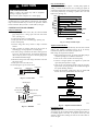
40GVC / 38GVC
40GVQ / 38GVQ
High---Wall Ductless Split Systems
Size 9K --- 36K
Installation Instruction
NOTE: Read the entire instruction manual before starting the installation.
TABLE OF CONTENTS
PAGE
PARTS LIST . . . . . . . . . . . . . . . . . . . . . . . . . . . . . . . . . . . . . . . 1
SAFETY CONSIDERATIONS . . . . . . . . . . . . . . . . . . . . . . . . . 2
SYSTEM REQUIREMENTS . . . . . . . . . . . . . . . . . . . . . . . . 2--3
DIMENSIONS . . . . . . . . . . . . . . . . . . . . . . . . . . . . . . . . . . . . 4--6
CLEARANCES . . . . . . . . . . . . . . . . . . . . . . . . . . . . . . . . . . . . . 7
INSTALLATION GUIDE . . . . . . . . . . . . . . . . . . . . . . . . . . . . . 8
INDOOR UNIT INSTALLATION . . . . . . . . . . . . . . . . . . . . . 8--9
Install Mounting Plate . . . . . . . . . . . . . . . . . . . . . . . . . . . . . 8
Drill Hole in Wall for Interconnecting Piping, Drain
and Wiring . . . . . . . . . . . . . . . . . . . . . . . . . . . . . . . . . . . . . 9
OUTDOOR UNIT INSTALLATION . . . . . . . . . . . . . . . . . . 9--10
Piping Connections . . . . . . . . . . . . . . . . . . . . . . . . . . . . . . . 9
Outdoor Unit Wiring Connections . . . . . . . . . . . . . . . . . . 10
INSTALL ALL POWER, INTERCONNECTING WIRING AND
PIPING TO INDOOR UNIT . . . . . . . . . . . . . . . . . . . . . . . . . . 10
SYSTEM VACUUM AND CHARGE . . . . . . . . . . . . . . . . . . . 11
START--UP . . . . . . . . . . . . . . . . . . . . . . . . . . . . . . . . . . . . . . . . 12
WIRING DIAGRAMS . . . . . . . . . . . . . . . . . . . . . . . . . . . . . . . 13
TROUBLESHOOTING . . . . . . . . . . . . . . . . . . . . . . . . . . . 14--17
The following parts are included in your indoor unit.
contact your dealer if any parts are damaged or missing:
Parts
Mounting Plate
Mounting Hardware
Remote Control
Remote Control Holder
Battery (1.5V)
Qty
1
7
1
1
2
Please
SAFETY CONSIDERATIONS
Installing, starting up, and servicing air--conditioning equipment
can be hazardous due to system pressures, electrical components,
and equipment location (roofs, elevated structures, etc.).
Only trained, qualified installers and service mechanics should
install, start--up, and service this equipment.
Untrained personnel can perform basic maintenance functions such
as cleaning coils. All other operations should be performed by
trained service personnel.
When working on the equipment, observe precautions in the
literature and on tags, stickers, and labels attached to the
equipment.
Follow all safety codes. Wear safety glasses and work gloves. Keep
quenching cloth and fire extinguisher nearby when brazing. Use
care in handling, rigging, and setting bulky equipment.
Read these instructions thoroughly and follow all warnings or
cautions included in literature and attached to the unit. Consult
local building codes and current editions of the National Electrical
Code ( NEC ) NFPA 70. In Canada, refer to current editions of the
Canadian electrical code CSA 22.1.
Recognize safety information. This is the safety--alert symbol !! .
When you see this symbol on the unit and in instructions or
manuals, be alert to the potential for personal injury.Understand
these signal words: DANGER, WARNING, and CAUTION.
These words are used with the safety--alert symbol. DANGER
identifies the most serious hazards which will result in severe
personal injury or death. WARNING signifies hazards which
could result in personal injury or death. CAUTION is used to
identify unsafe practices which may result in minor personal injury
or product and property damage. NOTE is used to highlight
suggestions which will result in enhanced installation, reliability, or
operation.
WARNING
!
CAUTION
!
EQUIPMENT DAMAGE HAZARD
Failure to follow this caution may result in equipment
damage or improper operation.
Do not bury more than 36 in. (914 mm) of refrigerant pipe
in the ground. If any section of pipe is buried, there must be
a 6 in. (152 mm) vertical rise to the valve connections on
the outdoor units. If more than the recommended length is
buried, refrigerant may migrate to the cooler buried section
during extended periods of system shutdown. This causes
refrigerant slugging and could possibly damage the
compressor at start--up.
GENERAL
These instructions cover the installation, start--up and servicing of
38GVC(Q) outdoor and 40GVC(Q) indoor units duct free systems.
SYSTEM REQUIREMENTS
Allow sufficient space for airflow and servicing unit. See Fig. 6
for minimum required distances between unit and walls or ceilings.
Piping
IMPORTANT: Both refrigerant lines must be insulated
separately.
S Minimum refrigerant line length between the indoor and outdoor
units is 10 ft. (3 m).
S The following maximum lengths are allowed:
Unit Size
9K
12K
18, 24K
30, 36K
REFRIGERANT LINE LENGTHS ft. (m)
Max Elevation
Max Elevation
Max Line Length
(ID over OD)
(OD over ID)
50 (15)
50 (15)
82 (25)
98 (30)
33 (10)
33 (10)
33 (10)
33 (10)
33 (10)
33 (10)
33 (10)
33 (10)
S The following are the piping sizes.
ELECTRICAL SHOCK HAZARD
Unit Size
9, 12K
18, 24K
30, 36K
Failure to follow this warning could result in personal
injury or death.
Before installing, modifying, or servicing system, main
electrical disconnect switch must be in the OFF
position. There may be more than 1 disconnect switch.
Lock out and tag switch with a suitable warning label.
PIPE SIZES
Mix Phase
1/4”
1/4”
1/4”
Vapor
3/8”
1/2”
5/8”
Refrigerant Charge
Unit
Size
Charge Amount *
LBS (kg)
Additional Charge Amount **
oz/ft (g/m)
Metering Device ***
Cool Only
Heat Pump
Cool Only
Heat Pump
Cool Only
9K
2.31 (1.05)
2.31 (1.05)
0.16 (15)
0.16 (15)
Capillary
12K 115v
2.54 (1.15)
2.54 (1.15)
0.16 (15)
0.22 (20)
Capillary
12K 208/230v
2.2 (1.00)
2.2 (1.0)
0.16 (15)
0.22 (20)
Capillary
18K
2.75 (1.25)
2.87 (1.30)
0.16 (15)
0.22 (20)
Capillary
24K
3.42 (1.55)
3.42 (1.55)
0.16 (15)
0.22 (20)
EXV
30K
--- --- --- --5.29 (2.40)
--- --- --- --0.54 (50)
--- --- --- --36K
5.30 (2.40)
5.73 (2.60)
0.54 (50)
0.54 (50)
Capillary
* Charge is for piping that runs up to 25 ft. (7.6 m)
** For piping runs greater than 25 ft. (7.6 m), add specified amount of charge per foot of extra piping, up to the allowable length.
*** EXV --- Electronic Expansion Device, Capillary tubes are used as metering devices
2
Heat Pump
Capillary
Capillary
Capillary
Capillary
EXV
EXV
EXV
Connecting (Power and Control Cable)
Power Wiring:
The main power is supplied to the outdoor unit. The field supplied
connecting cable from the outdoor unit to indoor unit consists of
three (3) wires and provides the power for the indoor unit. Two
wires are high voltage AC power and one is a ground wire.
Consult your local building codes and the NEC (National
Electrical Code) or CEC (Canadian Electrical Code) for special
requirements.
All wires must be sized per NEC or CEC and local codes. Use
Electrical Data table MCA (minimum circuit amps) and MOCP
(maximum over current protection) to correctly size the wires and
the disconnect fuse or breakers respectively.
Per caution note, only copper conductors with a minimum 300 volt
rating and 2/64--inch thick insulation must be used.
!
EQUIPMENT DAMAGE HAZARD
Failure to follow this caution may result in equipment
damage or improper operation.
S Wires should be sized based on NEC and local codes.
S Use copper conductors only with a minimum 300 volt .
rating and 2/64 inch thick insulation.
!
18 AWG
16 AWG
CAUTION
EQUIPMENT DAMAGE HAZARD
Failure to follow this caution may result in equipment
damage or improper operation.
Control Wiring:
A separate shielded copper conductor only, with a minimum 300
volt rating and 2/64--inch thick insulation, must be used as the
communication wire from from the outdoor unit to the indoor unit.
To minimize voltage drop of the control wire, use the following
wire size and maximum lengths shown in the chart below.
Wire Size
CAUTION
S Be sure to comply with local codes while running wire
from indoor unit to outdoor unit.
S Every wire must be connected firmly. Loose wiring may
cause terminal to overheat or result in unit malfunction.
A fire hazard may also exist. Therefore, be sure all
wiring is tightly connected.
Length
ft (m)
50 ft. (15 m)
50 ft (15) to 100 ft. (30 m)
S No wire should be allowed to touch refrigerant tubing,
compressor or any moving parts.
S Disconnecting means must be provided and shall be
located within sight and readily accessible from the air
conditioner.
S Connecting cable with conduit shall be routed through
hole in the conduit panel.
Electrical Data
Unit Size
System Voltage
Volts--- Ph.--- Freq.
Operating
Voltage
(Min/Max)
Compressor
RLA
LRA
Outdoor Fan
Indoor Fan
Volts
FLA
Output
Watts
Volts
FLA
Output
Watts
MCA
Max
Fuse/CB
Amps
(MOCP)
9K--- AC
115--- 1--- 60
103/127
9.76
25
115 AC
0.17
30
115 V--- AC
0.38
15.0
13
20
9K--- HP
115--- 1--- 60
103/127
9.76
20
176--- 375 DC
0.17
30
115 V--- AC
0.38
15.0
13
20
12K--- AC
115--- 1--- 60
103/127
11.20
25
115 AC
0.17
30
115 V--- AC
0.38
15.0
15
25
12K--- HP
115--- 1--- 60
103/127
11.20
20
176--- 375 DC
0.17
30
115 V--- AC
0.38
15.0
15
25
12K
208/230--- 1--- 60
187/253
7.30
16.5
208/230 AC
0.25
21
208/230 V--- AC
0.19
15.0
10
15
18K
208/230--- 1--- 60
187/253
10.86
27
208/230 AC
0.62
60
208/230 V--- AC
0.32
20.0
15
25
24K
208/230--- 1--- 60
187/253
11.71
41
208/230 AC
0.62
60
208/230 V--- AC
0.45
35.0
16
25
30K
208/230--- 1--- 60
187/253
13.45
40
310 DC
0.45
100
208/230 V--- AC
0.40
40.0
20
30
36K--- AC
208/230--- 1--- 60
187/253
16.92
67
310 DC
0.73
100
208/230 V--- AC
0.47
60.0
24
35
36K--- HP
208/230--- 1--- 60
187/253
17.50
67
310 DC
0.73
170
208/230 V--- AC
0.47
60.0
24
40
3
DIMENSIONS -- INDOOR
W
D
H
A12377
Unit Size
9K
12K
18K
24K
30/36 K
W
In. (mm)
30.3 (770)
30.3 (770)
34.0 (865)
39.7 (1008)
53.1 (1349)
H
In. (mm)
11.1 (283)
11.1 (283)
12.0 (305)
12.6 (319)
12.8 (325)
D
In. (mm)
7.9 (201)
7.9 (201)
8.5 (215)
8.7 (221)
10.0 (254)
Net Operating Weight
Lbs. (Kg)
18.7 (8.5)
19.8 (9.0)
26.5 (12.0)
33.1 (15.0)
44.1 (20.0)
Fig. 1 --- Indoor Unit Dimensions
DIMENSIONS - OUTDOOR
10.1 (257)
21.3 (540)
30.0 (762)
12.6 (320)
33.4 (848)
11.7 (267)
Unit: IN. (mm)
21.3 (540)
Fig. 2 --- 9K and 12K 115V (Net Operating Weight: 75 lbs. / 34 kg)
4
A12531
DIMENSIONS - OUTDOOR CONTINUED
25.9 (658)
21.7 (551)
10.8 (274)
28.0 (711)
12.5 (318)
18.5 (470)
Unit: IN. (mm)
11.8 (300)
Unit: IN. (mm)
A12532
Fig. 3 --- 12K 230V (Net Operating Weight: 63.8 lbs. / 30 kg)
35.0 (890)
27.6 (700)
13.4 (340)
37.9 (963)
15.6 (396)
22.0 (560)
14.3 (364)
Unit: IN. (mm)
Fig. 4 --- 18K and 24K (Net Operating Weight: 112.2 lbs. / 51 kg)
5
A12533
DIMENSIONS - OUTDOOR CONTINUED
36
(914.4)
14.6
(370.8)
31.1
(789.9)
16.7
(424.2)
38.6
(980.4)
24
(609.6)
15.7
(398.8)
in. (mm)
Fig. 5 --- 30K and 36K (Net Operating Weight: 30K = 154 lbs. / 70 kg; 36K = 161 lbs. / 73 kg)
6
A12379
CLEARANCES
Indoor Unit
Distance to Ceiling
6 in (152 mm)
Distance to Wall
6 in (152 mm)
Distance to Wall
6 in (152 mm)
Distance in Front of Unit
118 in (2997 mm)
Distance to Floor
66 in (1676 mm)
NOTE: Refrigerant lines
may be routed in any of the
(4) directions, right,
right rear, left, or left rear.
See instructions for details
● The clearance dimensions are necessary for a correct installation
and are the minimum permissible distances to adjacent structures.
Outdoor Unit
Above Unit
20 in (508 mm)
Air Inlet Side
12 in (305 mm)
Distance to
Back Wall
12 in (305 mm)
Distance to Wall
20 in (508 mm)
Air Discharge Side
79 in (2007 mm)
valve cover
A12385
Fig. 6 --- Indoor and Outdoor Unit Clearances
7
INSTALLATION GUIDE
30.3 (770)
10.2 (258.5)
Unit: IN. (mm)
A12534
Fig. 7 --- 09 and 12K Mounting Plate Spacing
34.1 (865)
6.9
(175)
5.9
(150)
21.3 (540)
Φ55
Φ55
1.6 (40)
1.6 (40)
Unit: IN. (mm)
A12535
Fig. 8 --- 18k Mounting Plate Spacing
39.7 (1008)
27.0 (685)
5.1 (130)
7.6 (193)
Φ55
12.6 (319)
INDOOR UNIT INSTALLATION
INSTALL MOUNTING PLATE
1. Carefully remove the mounting plate from the unit box.
2. The mounting plate should be located horizontally and level
on the wall. All minimum spacings shown in Fig. 7
through Fig. 10 should be maintained.
3. If the wall is block, brick, concrete or similar material, drill
.2” (5 mm) diameter holes and insert anchors for the appropriate mounting screws.
4. Attach the mounting plate to the wall.
21.6 (548.5)
50 (126.5)
11.1 (283)
Ideal installation locations include:
Indoor Unit
S A location where there are no obstacles near inlet and outlet area.
S A location which can bear the weight of indoor unit.
S Do not install indoor units near a direct source of heat such as
direct sunlight or a heating appliance.
S A location which provides appropriate clearances as outlined in
Fig. 6. Be sure to leave enough distance to allow access for
routine maintenance. The installation site should be 66 in (1676
mm) or more above the floor.
S Select a place away from potential electronic interference.
S Select a place where the filter can be easily removed.
Outdoor Unit
S A location which is convenient to installation and not exposed to
strong wind.
S A location which can bear the weight of outdoor unit and where
the outdoor unit can be mounted in a level position.
S A location which provides appropriate clearances as outlined in
Fig. 6.
S Do not install the indoor or outdoor units in a location with
special environmental conditions.
S Make sure the outdoor unit is installed in accordance with the
installation instructions and is convenient for maintenance and
repair.
S See the refrigerant piping table for the maximum height
difference between indoor and outdoor units and the maximum
length of the connecting tubing.
Φ55
2.0 (50)
2.0 (50)
3.9
(100)
Unit: IN. (mm)
4.9
(124)
Fig. 9 --- 24k Mounting Plate Spacing
10.0
(254.0)
A12536
13.7
(348.0)
29.4
(746.8)
Unit: IN. (mm)
Fig. 10 --- 30/36k Mounting Plate Spacing
Wall
Wall
Mark middle
Level
6 in.
See Hole
Size Tables
6 in.
(Rear piping hole)
(Rear piping hole)
Fig. 11 --- Mounting Plate Spacing
8
See Hole
Size Tables
A12537
A12584
DRILL HOLE IN WALL FOR INTERCONNECTING
PIPING, DRAIN AND WIRING
OUTDOOR UNIT INSTALLATION
1. Use a rigid base to support unit in a level position.
2. Locate outdoor unit and connect piping and wiring.
Refrigerant Line Routing
The refrigerant lines may be routed in any of the four directions
shown in Fig. 12.
For maximum serviceability, it is recommended to have refrigerant
line flare connections and the drain connection on the outside of
the wall that the fan coil is mounted on.
!
CAUTION
EQUIPMENT DAMAGE HAZARD
Failure to follow this caution may result in equipment
damage or improper operation.
Excessive torque can break flare nut depending on
installation conditions.
As viewed from front
Knockout 3
(030, 036 only)
Knockout 2
3
1 Right Exit
2 Right Rear Exit
(a)
4
Knockout 1
Left Exit
Left Rear Exit
(b)
(c)
Fig. 12 --- Refrigerant Line Routing
A12585
If piping is going through the back:
1. Determine pipe hole position using the mounting plate as a
template. Drill pipe hole diameter per chart below. The
outside pipe hole is 1/2--in. (13 mm) min. lower than inside
pipe hole, so it slants slightly downward (see Fig. 13).
If piping is going to exit from the left rear, it is recommended to field--fabricate piping extensions to get the flare connections to the outside of the wall.
1/2 in. (13 mm)
Min.
INDOOR
OUTDOOR
A07371
Model Size
9k, 12k and 18k
24k, 30k, 36k
Hole Diameter
in. (mm)
2.2 (56)
2.8 (71)
Fig. 13 --- Drill Holes
Piping Connections to Outdoor Unit
IMPORTANT: Use refrigeration grade tubing ONLY. No
other type of tubing may be used. Use of other types of tubing
will void manufacturer’s warranty.
Make sure there is enough piping to cover the required length
between the outdoor and indoor unit.
Only use piping suitable for high side pressure for both high
side and low side connections.
Piping Guide:
S Do not open service valves or remove protective caps from
tubing ends until all the connections are made.
S Bend tubing with bending tools to avoid kinks and flat spots.
S Keep the tubing free of dirt, sand, moisture, and other
contaminants to avoid damaging the refrigerant system.
S Avoid sags in the suction line to prevent the formation of oil
traps. Insulate each tube with minimum 3/8--in. (10 mm) wall
thermal pipe insulation. Inserting the tubing into the insulation
before making the connections will save time and improve
installation quality.
1. Remove service valve cover if provided with unit.
2. Cut tubing with tubing cutter.
3. Install correct size flare nut onto tubing and make flare connection.
4. Apply a small amount of refrigerant oil to the flare connection on the tubing.
5. Properly align tubing in with service valve.
6. Tighten flare nut and finish installation using two wrenches
as shown in Fig. 14.
If piping is going through the right or left side:
1. Use a small saw blade to carefully remove the corresponding plastic covering on side panel and drill the appropriate
size hole where the pipe is going through the wall. See Fig.
19.
2. Remove knockout 1 to run just the wiring. Remove knockout 1 and 2 or knockout 1, 2 and 3 if you are running both
piping and wiring through the side of the unit. See Fig. 12.
NOTE: If required, a condensate pump is available for the
application.
Fig. 14 --- Tighten Flare Nut
A07354
Strong
wind
Fig. 15 --- High Wind Installation
9
A07350
Outdoor Unit Wiring Connections
1. Mount outdoor power disconnect.
2. Run power wiring from main box to disconnect per NEC
and local codes. Set outdoor unit in place.
3. Remove field wiring cover from unit by removing screws.
4. Connect conduit to the conduit panel. (See Fig. 16)
5. Properly connect both power supply and control lines to terminal block per the connection diagram.
6. Ground unit in accordance with NEC and local electrical
codes.
7. Use lock nuts to secure conduit.
8. Reinstall field wiring cover.
Fig. 17 --- Hanging Indoor Unit
5. Open front cover of indoor unit and remove field wiring terminal block cover (see Fig. 18)
Field Wiring Cover
Field Wiring
Cover
Interconnecting
Cable
Conduit Panel
Fig. 18 --- Field Wiring Cover
lock nut
conduit
Finish
Fig. 16 --- Field Wiring
!
A12539
CAUTION
EQUIPMENT DAMAGE HAZARD
Failure to follow this caution may result in equipment
damage or improper operation.
S Be sure to comply with local codes while running wire
from indoor unit to outdoor unit.
S Every wire must be connected firmly. Loose wiring may
cause terminal to overheat or result in unit malfunction.
A fire hazard may also exist. Therefore, be sure all wiring
is tightly connected.
S No wire should be allowed to touch refrigerant tubing,
compressor or any moving parts.
S Disconnecting means must be provided and shall be
located within sight and readily accessible from the air
conditioner.
S Connecting cable with conduit shall be routed through
hole in the conduit panel.
A08283
A08279
6. Pull interconnecting wire up from back of indoor unit and
position in close to the terminal block on indoor unit.
7. Push bottom of indoor unit onto mounting plate to complete wall mount.
8. Connect wiring from outdoor unit per connection diagram
(see Fig. 26).
NOTE:
Polarity of power wires must match original
connection on outdoor unit.
9. Replace field wiring cover and close front cover of indoor
unit.
10. Connect refrigerant piping and drain line outside of indoor
unit. Refer to Fig. 14 for proper installation of flare connections. Complete pipe insulation at flare connection then
fasten piping and wiring to the wall as required. Completely seal the hole in the wall.
Knockout 3 (030, 036 Only)
Knockout 2
Knockout 1
Fig. 19 --- Remove Knockouts
Fixing hook
INSTALL ALL POWER, INTERCONNECTING
WIRING, AND PIPING TO INDOOR UNIT.
Mounting
1. Run interconnecting piping and wiring from outdoor unit to
indoor unit.
2. Pass interconnecting cable through hole in wall (outside to
inside).
3. Lift indoor unit into position and route piping and drain
through hole in wall (inside to outside). Fit interconnecting
wiring into back side of indoor unit.
4. Hang indoor unit on upper hooks of wall mounting plate (as
shown in Fig. 17 and Fig. 20)
A12540
Mounting
plate
plate
Fig. 20 --- Hang Indoor Unit
10
A12408
CAUTION
!
UNIT DAMAGE HAZARD
Failure to follow this caution may result in equipment
damage or improper operation.
Deep Vacuum Method
The deep vacuum method requires a vacuum pump capable of
pulling a vacuum of 500 microns and a vacuum gage capable of
accurately measuring this vacuum depth. The deep vacuum method
is the most positive way of assuring a system is free of air and
liquid water. (See Fig. 23)
5000
4500
4000
3500
3000
2500
2000
1500
1000
500
Never use the system compressor as a vacuum pump.
SYSTEM VACUUM AND CHARGE
Using Vacuum Pump
1. Completely tighten flare nuts A, B, C, D, connect manifold
gage charge hose to a charge port of the low side service
valve. (See Fig. 21.)
2. Connect charge hose to vacuum pump.
3. Fully open the low side of manifold gage. (See Fig. 22)
4. Start vacuum pump
5. Evacuate using either deep vacuum or triple evacuation
method.
6. After evacuation is complete, fully close the low side of
manifold gage and stop operation of vacuum pump.
7. The factory charge contained in the outdoor unit is good for
up to 25 ft. (8 m) of line length. For refrigerant lines longer
than 25 ft (8 m), add 0.1 oz. per foot of extra piping up to
the maximum allowable length.
8. Disconnect charge hose from charge connection of the low
side service valve.
9. Fully open service valves B and A.
10. Securely tighten caps of service valves.
Indoor Unit
Refrigerant
Outdoor Unit
A
Low Side
B
High Side
C
D
LEAK IN
SYSTEM
MICRONS
Refrigerant tubes and indoor coil should be evacuated using the
recommended deep vacuum method of 500 microns. The alternate
triple evacuation method may be used if the procedure outlined
below is followed. Always break a vacuum with dry nitrogen.
VACUUM TIGHT
TOO WET
TIGHT
DRY SYSTEM
0
1
2
3 4
5
MINUTES
6
7
Fig. 23 --- Deep Vacuum Graph
A95424
Triple Evacuation Method
The triple evacuation method should only be used when vacuum
pump is only capable of pumping down to 28 in. of mercury
vacuum and system does not contain any liquid water.
Refer to Fig. 24 and proceed as follows:
1. Pump system down to 28 in. of mercury and allow pump to
continue operating for an additional 15 minutes.
2. Close service valves and shut off vacuum pump.
3. Connect a nitrogen cylinder and regulator to system and
open until system pressure is 2 psig.
4. Close service valve and allow system to stand for 1 hr. During this time, dry nitrogen will be able to diffuse throughout
the system absorbing moisture.
5. Repeat this procedure as indicated in Fig. 24. System will
then be free of any contaminants and water vapor.
EVACUATE
Service Valve
A07360
Fig. 21 --- Service Valve
BREAK VACUUM WITH DRY NITROGEN
WAIT
Manifold Gage
EVACUATE
BREAK VACUUM WITH DRY NITROGEN
500 microns
Low side valve
Charge hose
WAIT
High side valve
EVACUATE
Charge hose
CHECK FOR TIGHT, DRY SYSTEM
(IF IT HOLDS DEEP VACUUM)
Vacuum pump
RELEASE CHARGE INTO SYSTEM
Low side valve
Fig. 22 --- Manifold
Fig. 24 --- Triple Evacuation Method
A07361
A95425
Final Tubing Check
IMPORTANT: Check to be certain factory tubing on both indoor
and outdoor unit has not shifted during shipment. Ensure tubes are
not rubbing against each other or any sheet metal. Pay close
attention to feeder tubes, making sure wire ties on feeder tubes are
secure and tight.
11
START--UP
Test Operation
Perform test operation after completing gas leak and electrical
safety check.
1. Push the “ON/OFF” button on Remote Control to begin
testing.
NOTE: A protection feature prevents the air conditioner from
being activated for approximately 3 minutes.
2. Push MODE button, select COOLING, HEATING, FAN
mode to check if all functions work correctly.
INSTALLATION AND MAINTENANCE OF FILTER
1. Grasp the front panel by it’s two ends and lift the panel and
then remove the air filter.
2. Install a clean air filter along the arrow direction and close
the panel.
SYSTEM CHECKS
1. Conceal the tubing where possible.
2. Make sure that the drain tube slopes downward along its entire length.
3. Ensure all tubing and connections are properly insulated.
4. Fasten tubes to the outside wall, when possible.
5. Seal the hole through which the cables and tubing pass.
INDOOR UNIT
1.
2.
3.
4.
Do all Remote Control buttons function properly?
Do the display panel lights work properly?
Does the air deflection louver function properly?
Does the drain work?
Air filter
OUTDOOR UNIT
1. Are there unusual noises or vibrations during operation?
Explain Following Items To Customer With The Aid Of The
Owner’s Manual:
1. How to turn air conditioner on and off; selecting
COOLING, HEATING and other operating modes; setting
a desired temperature; setting the timer to automatically start
and stop air conditioner operation; and all other features of
the Remote Control and display panel.
2. How to remove and clean the air filter.
3. How to set air deflection louver.
4. Explain care and maintenance.
5. Present the Owner’s Manual and installation instructions to
customer.
Auxiliary filter
Fig. 25 --- Install Air Filter
12
A12541
WIRING DIAGRAMS
38GV/40GV 9K~12K 115-1-60 Connection Diagram
CONNECTING CABLE
OUTDOOR TO INDOOR
N
S
L
L
N
Pow er to Control Pow er to
Indoor to Indoor
Indoor
Unit
Unit
Unit
Main
Pow er
Supply
Main
Pow er
Supply
115-1-60 Low V DC 115-1-60
115-1-60
115-1-60
GND
N
S
L
GND
Ground
Pow er
from
Outdoor
Unit
Control
from
Outdoor
Unit
Pow er
from
Outdoor
Unit
Ground
115-1-60
Low V DC
115-1-60
38GV 9K~12K Outdoor Unit Terminal Block
40GV 9K~12K Indoor Unit Terminal Block
38GV/40GV 12K 208/230-1-60 Connection Diagram
CONNECTING CABLE
OUTDOOR TO INDOOR
L2
S
Pow er to
Indoor Unit
L1
GND
Control
Pow er to
to Indoor
Indoor Unit
Unit
L2
S
Ground
208/230-1-60 Low V DC 208/230-1-60
208/230-1-60
L2
L1
GND
Main Pow er
Supply
Main Pow er
Supply
Ground
208/230-1-60
208/230-1-60
L1
GND
Control
Pow er from
Pow er from
from
Outdoor Unit
Outdoor Unit Ground
Outdoor Unit
Low V DC
208/230-1-60
40GV 12K Indoor Unit Terminal Block
38GV 12K Outdoor Unit Terminal Block
38GV/40GV 18K~36K 208/230-1-60 Connection Diagram
CONNECTING CABLE
OUTDOOR TO INDOOR
L2
Pow er to
Indoor Unit
S
Control to
Indoor
Unit
208/230-1-60 Low V DC
L1
Pow er to
Indoor Unit
L1
L2
Main Pow er Main Pow er
Supply
Supply
GND
Ground
208/230-1-60 208/230-1-60 208/230-1-60
L2
S
L1
GND
Pow er from
Outdoor
Unit
Control
from
Outdoor
Unit
Pow er from
Outdoor
Unit
Ground
208/230-1-60 Low V DC 208/230-1-60
38GV 18K~36K Outdoor Unit Terminal Block
40GV 18K~36K Indoor Unit Terminal Block
NOTE: Polarity of power wires must match original connection on outdoor unit.
Fig. 26 --- Unit Wiring Diagrams
13
A12542
TROUBLESHOOTING
This unit has on--board diagnostics. Error codes will appear on the LED display on the front panel of the indoor unit in place of the
temperature display. Error codes are also displayed on the outdoor unit microprocessor board with colored LED lights. The table below
explains the error codes for both units.
Diagnostic Codes
38/40GVC/Q 9k / 12k, 115v
Malfunction
Error Code
on indoor unit
Repair Method/Cause
Indoor PCB Malfunction
EE
Replace indoor main board
Anti--- freeze Protection
E2
Outdoor ambient temperature is too low
System overload protection
H4
Check for dirty or blocked heat exchangers
Indoor motor malfunction
H6
Check motor mounting and wiring
Indoor pipe temperature sensor malfunction
F2
Measure the resistance value in the sensor
Return air temperature sensor malfunction
F1
Measure the resistance value in the sensor
Indoor board malfunction
UF
Replace indoor main board
Compressor overload protection
H3
Check overload wiring
Compressor start--- up failure
Lc
Check if the resistance of the compressor and the resistance to
ground is normal. If the resistance is normal, the outdoor main
board may be defective.
Outdoor fan motor failure
UH
Check outdoor motor
Low voltage protection
E5
Check incoming power
4--- way valve malfunction
U7
Replace 4--- way valve
Compressor phase detection error
U1
Replace outdoor main board
Compressor speed reduction
H7
Check if the resistance of the compressor and the resistance to
ground is normal. If the resistance is normal, the outdoor main
board may be defective.
Current detection malfunction
U5
Replace outdoor main board
Outdoor ambient temperature sensor
malfunction
F3
Measure the resistance value in the sensor
Discharge temperature sensor malfunction
(out of range)
E4
Measure the resistance value in the sensor
Discharge temperature sensor malfunction
(open or shorted)
F5
Measure the resistance value in the sensor
Condenser temperature sensor malfunction
(open or shorted)
F4
Measure the resistance value in the sensor
Heat sink over--- temperature
P8
Is outdoor ambient temperature out of system operating range?
Is heat sink blocked or damaged?
DC over--- current
UU
--- ---
Heat sink temperature sensor malfunction
P7
Replace outdoor main board
Low charge
F0
Check for leaks
DC input voltage is too high
PH
Check incoming power supply
DC input voltage is too low
PL
Check incoming power supply
Communication malfunction
E6
Check wiring connection
Indoor and outdoor unit mismatched
UA
Check system combination
14
TROUBLESHOOTING (CONTINUED)
Diagnostic Codes
38/40GVC/Q 12K, 230v
Malfunction
Error Code on indoor unit
Repair Method/Cause
Indoor PCB Malfunction
EE
Replace indoor main board
Anti--- freeze Protection
E2
Outdoor ambient temperature is too low
System overload protection
H4
Check for dirty or blocked heat exchangers
Indoor motor malfunction
H6
Check motor mounting and wiring
Indoor pipe temperature sensor malfunction
F2
Measure the resistance value in the sensor
Return air temperature sensor malfunction
F1
Measure the resistance value in the sensor
Indoor board malfunction
UF
Replace indoor main board
Compressor overload protection
H3
Check overload wiring
Compressor start--- up failure
Lc
Check if the resistance of the compressor and the resistance to
ground is normal. If the resistance is normal, the outdoor main
board may be defective.
Outdoor fan motor failure
UH
Check outdoor motor
Low voltage protection
E5
Check incoming power
4--- way valve malfunction
U7
Replace 4--- way valve
Compressor phase detection error
U1
Replace outdoor main board
Compressor speed reduction
H7
Check if the resistance of the compressor and the resistance to
ground is normal. If the resistance is normal, the outdoor main
board may be defective.
Current detection malfunction
U5
Replace outdoor main board
Outdoor ambient temperature sensor malfunction
F3
Measure the resistance value in the sensor
Discharge temperature sensor malfunction
(out of range)
E4
Measure the resistance value in the sensor
Discharge temperature sensor malfunction
(open or shorted)
F5
Measure the resistance value in the sensor
Condenser temperature sensor malfunction
(open or shorted)
F4
Measure the resistance value in the sensor
Heat sink over temperature
P8
Is outdoor ambient temperature out of system operating range?
Is heat sink blocked or damaged?
DC over--- current
H5
--- ---
Heat sink temperature sensor malfunction
P7
Replace outdoor main board
Low charge
F0
Check for leaks
DC input voltage is too high
PH
Check incoming power supply
DC input voltage is too low
PL
Check incoming power supply
Communication malfunction
E6
Check wiring connection
Indoor and outdoor unit mismatched
UA
Check system combination
15
TROUBLESHOOTING (CONTINUED)
Diagnostic Codes
38/40GVC/Q 18k--24k, 230v
Error Code
on indoor unit
Repair Method/Cause
System high pressure protection
E1
Poor heat exchange. Are the coils clogged or blocked? Is the ambient temperature out of system range?
Anti--- freeze Protection
E2
Outdoor ambient temperature is too low
Discharge temperature sensor malfunction
(out of range)
E4
Measure the resistance value in the sensor
Low voltage protection
E5
Check incoming power
Communication malfunction
E6
Check wiring connection
System overload protection
E8
Refer to Service Manual
Indoor board malfunction
U8
Replace indoor main board
Indoor motor malfunction
H6
Check motor mounting and wiring
Missing jumper from indoor board
C5
No jumper on controller or installed improperly or damaged. Corresponding circuit on main board has malfunction.
Return air temperature sensor malfunction
F1
Measure the resistance value in the sensor
Indoor pipe temperature sensor malfunction
F2
Measure the resistance value in the sensor
Outdoor ambient temperature sensor malfunction
F3
Measure the resistance value in the sensor
Condenser temperature sensor malfunction
(open or shorted)
F4
Measure the resistance value in the sensor
Discharge temperature sensor malfunction
(open or shorted)
F5
Measure the resistance value in the sensor
Overload limit, compressor speed reduction
F6
Refer to Service Manual
Over current compressor speed reduction
F8
System voltage is too low or system voltage is high
Compressor discharge temperature high,
compressor speed reduction
F9
Load is too great
Ambient temperature too high
Refrigerant is low
Electric expansion valve malfunction
Over voltage protection
PH
Check incoming power supply
Current detection malfunction
U5
Replace outdoor main board
Compressor current protection
P5
Refer to Service Manual. Check inverter board.
Defrosting
H1
H1 signal normal operation
Compressor overload protection
H3
Check overload wiring
System overload protection
H4
Checked for dirty or blocked heat exchangers
IPM protection
H5
IPM module over temperature, low voltage, silica grease problem
PFC (power factor correction) board protection
HC
Refer to Service Manual
Compressor speed reduction
H7
Check if the resistance of the compressor and the resistance to
ground is normal. If the resistance is normal, the outdoor main
board may be defective.
Ambient temperature cut off range
H0
Refer to Service Manual (overload, high temperature, cutout)
Compressor start--- up failure
LC
Check if the resistance of the compressor and the resistance to
ground is normal. If the resistance is normal, the outdoor main
board may be defective.
Compressor phase detection error
U1
Replace outdoor main board
Malfunction
16
TROUBLESHOOTING (CONTINUED)
Diagnostic Codes
38/40GVC/Q 30k--36k, 230v
Malfunction
Error Code
on indoor unit
Repair Method/Cause
Defrosting
H1
H1 signal normal operation
Anti--- freeze Protection
E2
Outdoor ambient temperature is too low
IPM protection
H5
IPM module over temperature, low voltage, silica grease problem
Low voltage protection
E5
Check incoming power
System overload protection
H4
Checked for dirty or blocked heat exchangers
Discharge temperature sensor malfunction
(out of range)
E4
Measure the resistance value in the sensor
Compressor overload protection
H3
Check overload wiring, compressor shell overheat, low charge
Compressor high voltage/power protection
L9
Compressor voltage too high, ambient temperature out of range
IPM protection
H5
IPM module over temperature, low voltage, silica grease problem
Indoor PCB Malfunction
EE
Replace main indoor board
DC input voltage is too low
PL
Check incoming power supply
DC input voltage is too high
PH
Check incoming power supply
PFC (power factor correction) board protection
HC
Refer to Service Manual
Indoor motor malfunction
H6
Check motor mounting and wiring
Indoor and outdoor units mismatched
LP
Check system combination
Condenser temperature sensor malfunction
(open or shorted)
F4
Measure the resistance value in the sensor
Outdoor ambient temperature sensor
malfunction
F3
Measure the resistance value in the sensor
Discharge temperature sensor malfunction
(open or shorted)
F5
Measure the resistance value in the sensor
Return air temperature sensor malfunction
F1
Measure the resistance value in the sensor
Indoor pipe temperature sensor malfunction
F2
Measure the resistance value in the sensor
Communication malfunction
E6
Check wiring connection
Missing jumper from indoor board
C5
No jumper on controller or installed improperly or damaged. Corresponding circuit on main board has malfunction.
System high pressure protection
E1
Poor heat exchange. Are the coils clogged or blocked? Is the ambient temperature out of system range?
17
Copyright 2013 Carrier Corp. S 7310 W. Morris St. S Indianapolis, IN 46231
Edition Date: 07/13
Manufacturer reserves the right to change, at any time, specifications and designs without notice and without obligations.
18
Catalog No: 38---40GVC ---Q---2SI
Replaces: 38--- 40GVC--- Q--- 1SI