1
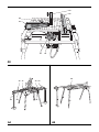
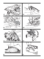
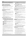
www.
.eu
DW743N
Copyright DEWALT
2
10 11
14
13
12
39
3
6
8
7
5
4
2
1
9
A1
14
15
16
22
20
17
18
19
21
A2
1
25
26
24
27
23
22
A3
35
30 31
28
A4
2
29
33 32
34
A5
36
37
29
A6
A7
38
X
A8
B
3
46
47
48
49
18
C2
C1
50
20
2
E1
56
23
55
52
D
4
E2
60
58
59
57
F1
F2
62 63
64
22
8
60 61
67
65
F3
G1
7
66
62
4
52
68
70
70
69
G2
H
66
62
22
71
I1
I2
5
72
7
J1
J2
73
74
K1
22
K2
77
76
75
16
12
2
L2
L1
16
62
16
3-8 mm
M
6
N
76
25
20
26
79
80
81
78
O
Q
77
P
R
17
S
T
82
U
81
V1
7
85
85
84
V2
W
8
83
V3
ENGLI SH
FLIP-OVER SAW DW743N
Congratulations!
You have chosen a DEWALT tool. Years of experience, thorough
product development and innovation make DEWALT one of the most
reliable partners for professional power tool users.
The vibration emission level given in this information sheet has been
measured in accordance with a standardised test given in EN 61029
and may be used to compare one tool with another. It may be used for
a preliminary assessment of exposure.
WARNING: The declared vibration emission level
represents the main applications of the tool. However if
the tool is used for different applications, with different
accessories or poorly maintained, the vibration emission
may differ. This may significantly increase the exposure level
over the total working period.
Technical Data
Voltage
(UK & Ireland only)
Type
Power input
230 V tools
115–120 V tools
No-load speed
Blade diameter
Blade bore
Blade body thickness
Blade tooth thickness
Riving knife thickness
Mitre (max. positions)
Bevel (max. positions)
Automatic blade brake time
Weight
V
V
W
W
min-1
mm
mm
mm
mm
mm
left
right
left
s
kg
Cutting capacities
Mitre saw mode (fig. b)
Cutting angle
DW743N
QS/GB
230
230/115
2
2,000
1,700
2,850
250
30
2.2
3
2.3
45°
45°
45°
< 10
37
DW743N DW743N
LX
DK
–
230
115
230/115
2
3
2,000
1,700
2,850
250
30
2.2
3
2.3
45°
45°
45°
< 10
37
Size of material
H mm B mm
Straight cross-cut
Table turned 45° right for mitre cuts
Table turned 45° left for mitre cuts
Sawhead tilted 45° left for bevel cuts
20
180
30
40
68
85
176
170
140
26
70
20
50
95
130
140
2,000
1,700
2,850
250
30
2.2
3
2.3
45°
45°
45°
< 10
37
Notes
Workpiece
place against
fence (X)
No packaging
piece required
An estimation of the level of exposure to vibration should
also take into account the times when the tool is switched
off or when it is running but not actually doing the job. This
may significantly reduce the exposure level over the total
working period.
Identify additional safety measures to protect the operator
from the effects of vibration such as: maintain the tool and
the accessories, keep the hands warm, organisation of
work patterns.
Fuses:
Europe
U.K. & Ireland
U.K. & Ireland
230 V tools
230 V tools
115 V tools
10 Amperes, mains
13 Amperes, in plugs
16 Amperes, mains
NOTE: This device is intended for the connection to a power supply
system with maximum permissible system impedance Zmax of 0.30 Ω
at the interface point (power service box) of user’s supply.
The user has to ensure that this device is connected only to a power
system which fulfils the requirement above. If necessary, the user can
ask the public power supply company for the system impedance at the
interface point.
Definitions: Safety Guidelines
The definitions below describe the level of severity for each signal word.
Please read the manual and pay attention to these symbols.
DANGER: Indicates an imminently hazardous situation
which, if not avoided, will result in death or serious injury.
WARNING: Indicates a potentially hazardous situation
which, if not avoided, could result in death or serious
injury.
CAUTION: Indicates a potentially hazardous situation
which, if not avoided, may result in minor or moderate
injury.
NOTICE: Indicates a practice not related to personal
injury which, if not avoided, may result in property
damage.
Cross-cut at
max. height
Denotes risk of electric shock.
Denotes risk of fire.
Bench Saw mode
Max. ripping capacity left/right
Depth of cut at 90°
Depth of cut at 45°
mm
mm
mm
210/210
0–70
0–32
210/210
0–70
0–32
210/210
0–70
0–32
LPA
KPA
LWA
KWA
dB(A)
dB(A)
dB(A)
dB(A)
93
3
106
2.9
93
3
106
2.9
93
3
106
2.9
Denotes sharp edges.
EC-Declaration of Conformity
MACHINERY DIRECTIVE
(sound pressure)
(sound pressure uncertainty)
(sound power)
(sound power uncertainty)
Vibration total values (triax vector sum) determined according to EN 61029-1
and EN 61029-2-11.
Vibration emission value ah
ah =
Uncertainty K =
m/s²
m/s²
2.0
1.5
2.0
1.5
2.0
1.5
DW743N
DEWALT declares that these products described under “technical data”
are in compliance with:
2006/42/EC, EN 61029-1, EN 61029-2-11.
These products also comply with Directive 2004/108/EC. For more
information, please contact DEWALT at the following address or refer to
the back of the manual.
The undersigned is responsible for compilation of the technical file and
makes this declaration on behalf of DEWALT.
9
EN GL I S H
13. Do not overreach.
Keep proper footing and balance at all times.
14. Maintain tools with care.
Horst Grossmann
Vice President Engineering and Product Development
DEWALT, Richard-Klinger-Straße 11,
D-65510, Idstein, Germany
01.01.2010
Safety Instructions
WARNING! When using electric tools basic safety
precautions should always be followed to reduce
the risk of fire, electric shock and personal injury
including the following.
Read all these instructions before attempting to operate this product
and save these instructions.
SAVE THIS MANUAL FOR FUTURE REFERENCE
General Safety Rules
1. Keep work area clear.
Cluttered areas and benches invite injuries.
2. Consider work area environment.
Do not expose the tool to rain. Do not use the tool in damp or wet
conditions. Keep the work area well lit (250 - 300 Lux). Do not use
the tool where there is a risk of causing fire or explosion, e.g., in the
presence of flammable liquids and gases.
3. Guard against electric shock.
Avoid body contact with earthed surfaces (e.g., pipes, radiators,
cookers and refrigerators). When using the tool under extreme
conditions (e.g., high humidity, when metal swarf is being
produced, etc.), electric safety can be improved by inserting an
isolating transformer or a (FI) earth-leakage circuit-breaker.
4. Keep other persons away.
Do not let persons, especially children, not involved in the work,
touch the tool or the extension cord and keep them away from the
work area.
5. Store idle tools.
When not in use, tools must be stored in a dry place and locked up
securely, out of reach of children.
6. Do not force the tool.
It will do the job better and safer at the rate to which it was
intended.
Keep cutting tools sharp and clean for better and safer
performance. Follow instructions for lubricating and changing
accessories. Inspect tools periodically and if damaged have
them repaired by an authorized service facility. Keep handles and
switches dry, clean and free from oil and grease.
15. Disconnect tools.
When not in use, before servicing and when changing accessories
such as blades, bits and cutters, disconnect tools from the power
supply.
16. Remove adjusting keys and wrenches.
Form the habit of checking to see that adjusting keys and
wrenches are removed from the tool before operating the tool.
17. Avoid unintentional starting.
Do not carry the tool with a finger on the switch. Be sure that the
tool is in the “off” position before plugging in.
18. Use outdoor extension leads.
Before use, inspect the extension cable and replace if damaged.
When the tool is used outdoors, use only extension cords intended
for outdoor use and marked accordingly.
19. Stay alert.
Watch what you are doing. Use common sense. Do not operate the
tool when you are tired or under the influence of drugs or alcohol.
20. Check for damaged parts.
Before use, carefully check the tool and mains cable to determine
that it will operate properly and perform its intended function.
Check for alignment of moving parts, binding of moving parts,
breakage of parts, mounting and any other conditions that may
affect its operation. A guard or other part that is damaged should
be properly repaired or replaced by an authorized service centre
unless otherwise indicated in this instruction manual. Have
defective switches replaced by an authorized service centre.
Do not use the tool if the switch does not turn it on and off.
Never attempt any repairs yourself.
WARNING! The use of any accessory or attachment or
performance of any operation with this tool other than
those recommended in this instruction manual may present
a risk of personal injury.
21. Have your tool repaired by a qualified person.
This electric tool complies relevant safety rules. Repairs should
only be carried out by qualified persons using original spare parts;
otherwise this may result in considerable danger to the user.
7. Use the right tool.
Do not force small tools to do the job of a heavy duty tool. Do
not use tools for purposes not intended; for example do not use
circular saws to cut tree limbs or logs.
8. Dress properly.
Do not wear loose clothing or jewellery, as these can be caught in
moving parts. Non-skid footwear is recommended when working
outdoors. Wear protective hair covering to contain long hair.
9. Use protective equipment.
Always use safety glasses. Use a face or dust mask if working
operations create dust or flying particles. If these particles might
be considerably hot, also wear a heat-resistant apron. Wear ear
protection at all times. Wear a safety helmet at all times.
10. Connect dust extraction equipment.
If devices are provided for the connection of dust extraction and
collecting equipment, ensure these are connected and properly
used.
11. Do not abuse the cord.
Never yank the cord to disconnect it from the socket. Keep the
cord away from heat, oil and sharp edges. Never carry the tool by
its cord.
12. Secure work.
Where possible use clamps or a vice to hold the work. It is safer
than using your hand and it frees both hands to operate the tool.
10
Additional Safety Rules for Flip-over Saws
• Do not allow untrained people to operate this machine.
• Do not use the saw to cut other than aluminium, wood or similar
materials.
• Select the correct saw blade for the material to be cut.
• Do not use cracked or damaged saw blades.
• Do not use HSS blades.
• Use correctly sharpened blades. Observe the maximum speed
marked on the saw blade.
• Use only saw blades recommended by the manufacturer and
which conform to EN 847-1.
• Do not use the saw without the guards and riving knife in position
and properly maintained, especially when changing from mitre saw
mode to bench saw mode, or vice versa.
• Make sure the floor area around the machine is level, well
maintained and free of loose materials, e.g. chips and cut-offs.
• Make sure adequate general or localized lighting is provided.
• Wear suitable personal protective equipment when necessary,
including:
– hearing protection to reduce the risk of induced hearing loss;
– respiratory protection to reduce the risk of inhalation of harmful
dust;
ENGLI SH
– gloves for handling saw blades and rough material. Saw blades
should be carried in a holder wherever practicable.
• Refrain from removing any cut-offs or other parts of the work piece
from the cutting area while the saw is running and the saw head is
not in the rest position.
• Replace the table insert when worn.
• Replace the table when the slot in the table is too wide.
• Do not use cracked or damaged saw blades.
• Do not use any abrasive discs.
• Raise the blade from the kerf in the workpiece prior to releasing the
switch.
• Ensure that the arm is securely fixed when performing bevel cuts.
• Do not wedge anything against the fan to hold the motor shaft.
• Ensure that the upper portion of the saw blade is completely
enclosed in the mitre sawing mode.
• The blade guard on your saw will automatically raise when the arm
is brought down; it will lower over the blade when the arm is raised.
The guard can be raised by hand when installing or removing saw
blades or for inspection of the saw. Never raise the blade guard
manually unless the saw is switched off.
• Ensure that the arm is securely fixed in the working position in the
bench sawing mode.
• Keep the surrounding area of the machine well maintained and free
of loose materials, e.g. chips and cut-offs.
• Ensure that the arm is securely fixed when bevelling in the bench
saw mode.
• Check periodically that the motor air slots are clean and free of
chips.
• Take care when grooving during the bench saw operation by using
appropriate guarding system. Slotting is not allowed.
• Replace the kerf plate when worn.
• Report faults in the machine, including guards or saw blades, to
your dealer as soon as they are discovered.
• Connect the saw to a dust collection device when sawing wood.
Always consider factors which influence exposure of dust such as:
-– Type of material to be machined (chip board produces more
dust than wood);
-– Correct adjustment of the saw blade;
-– Ensure that the local extraction as well as hoods, baffles and
chutes are properly adjusted.
-– Dust extractor with air velocity not less than 20 m/s
• Do not use any abrasive discs or diamond cutting wheels.
• Refrain from removing any cut-offs or other parts of the workpiece
from the cutting area while the machine is running and the saw
head is not in the rest position.
• In case of an accident or machine failure, immediately turn the
machine off and disconnect machine from the power source.
• Report the failure and mark the machine in suitable form to prevent
other people from using the defective machine.
• When the saw blade is blocked due to abnormal feed force during
cutting, turn the machine off and disconnect it from power supply.
Remove the workpiece and ensure that the saw blade runs free.
Turn the machine on and start new cutting operation with reduced
feed force.
• Disconnect the machine from the mains before carrying out any
maintenance work or when changing the blade.
• Never perform any cleaning or maintenance work when the
machine is still running and the head is not in the rest position.
• When possible, always mount the machine to a bench.
• If you use a laser to indicate the cutting line, make sure that the
laser is of class 2 according to EN 60825-1:2001. Do not replace
a laser diode with a different type. If damaged, have the laser
repaired by an authorised repair agent.
• Never use the machine in mitre saw mode as long as the guard is
not fitted (50, fig. D).
• Always use the push stick. Never cut workpiece shorter than
30 mm.
• Without additional support the machine is designed to accept the
maximum workpiece size of:
– Height 68 mm by width 140 mm by length 600 mm
– Longer workpieces need to be supported by suitable additional
table, e.g. DE3497. Always clamp the workpiece safely.
• Always clamp the workpiece safely.
Additional Safety Rules for Bench Saws
• Never cut light alloy, especially magnesium.
• Do not use saw blades with a body thickness greater or a width of
tooth smaller than the thickness of the riving knife.
• Whenever the situation allows, mount the machine to a bench
using bolts with a diameter of 8 mm and 80 mm in length (fig.C2).
• Make sure that the blade rotates in the correct direction and that
the teeth are pointing to the front of the bench saw.
Additional Safety Rules for Mitre Saws
• Be sure all clamp handles are tight before starting any operation.
• Make sure all locking knobs and clamp handles are tight before
starting any operation.
• Be sure all blade and flanges are clean and the recessed sides of
the collar are against the blade. Tighten the arbor nut securely.
• Do not operate the machine without the guard in position, or if the
guard does not function or is not maintained properly.
• Keep the saw blade sharp and properly set.
• Never use your saw without the kerf plate.
• Make sure that the riving knife is adjusted to the correct distance
from the blade - maximum 5 mm.
• Never place either hand in the blade area when the saw is
connected to the electrical power source.
• Never operate the saw without the upper and lower guards in
place.
• Never attempt to stop a machine in motion rapidly by jamming a
tool or other means against the blade; serious accidents can be
caused unintentionally in this way.
• Keep your hands out of the path of the saw blade.
• Before using any accessory consult the instruction manual. The
improper use of an accessory can cause damage.
• Use a push stick at all times, and ensure that you do not place
hands closer than 150 mm from the saw blade while cutting.
• Select the correct blade for the material to be cut.
• Do not attempt to operate on anything but the designated voltage.
• Observe the maximum speed marked on the saw blade.
• Do not apply lubricants to the blade when it is running.
• Use a holder or wear gloves when handling a saw blade.
• Do not reach around behind the saw blade.
• Ensure that the saw blade is mounted correctly before use.
• Always keep the push stick in its place when not in use.
• Make sure that the blade rotates in the correct direction. Keep the
blade sharp.
• Do not stand on top of the unit.
• Do not use blades of larger or smaller diameter than
recommended. For the proper blade rating refer to the technical
data. Use only the blades specified in this manual, complying with
EN 847-1.
• Consider applying specially designed noise-reduction blades.
• Do not use HSS blades.
• Disconnect the saw from the mains supply before changing blades
or carrying out maintenance.
• During transportation make sure that the upper part of the saw
blade is covered, e.g., by the guard.
• Do not use the guard for handling or transportation.
• Do not use blades with a body thickness greater or a width of tooth
smaller than the thickness of the riving knife.
• Consider applying specially designed noise-reduction blades.
11
EN GL I S H
• Always keep the push stick in its place when not in use.
Do not use the riving knife when using the machine in the
mitre saw mode. Make sure that the riving knife is secured in
the upper rest position (fig. A2).
• During transportation make sure that the upper part of the saw
blade is covered, e.g. by the guard.
Additional Safety Rules for Table Saws
Carrying point
• Rebating, slotting or grooving is not allowed.
• Always use the push stick. Never cut workpiece smaller than
30 mm.
• Without additional support the machine is designed to accept the
maximum workpiece size of:
– Height 70 mm by width 600 mm by length 1500 mm
DATE CODE POSITION (FIG. A1)
The Date Code (39), which also includes the year of manufacture, is
printed into the housing.
Example:
2010 XX XX
– Longer workpieces need to be supported by suitable additional
table, e.g. DE3497 or DE3472.
Residual Risks
The following risks are inherent to the use of saws:
– injuries caused by touching the rotating parts
In spite of the application of the relevant safety regulations and the
implementation of safety devices, certain residual risks cannot be
avoided. These are:
Year of Manufacture
Package Contents
The package contains:
1 Partly assembled machine
4 Legs
1 Box containing:
1 Top guard for bench saw position
– Impairment of hearing.
1 Under-table guard for mitre saw position
– Risk of accidents caused by the uncovered parts of the rotating
saw blade.
1 Parallel fence
– Risk of injury when changing the blade.
1 Push stick
1 Plastic bag containing:
– Risk of squeezing fingers when opening the guards.
4 M8 locking knobs
– Health hazards caused by breathing dust developed when sawing
wood, especially oak, beech and MDF.
4 M8 x 50 mushroom head bolts
4 D8 flat washers
The following factors are of influence to noise production:
– The material to be cut.
– The type of saw blade.
– The feed force.
The following factors increase the risk of breathing problems:
– No dust extractor connected when sawing wood.
1 Locking grommet
1 Instruction manual
1 Exploded drawing
• Check for damage to the tool, parts or accessories which may
have occurred during transport.
– Insufficient dust extraction caused by uncleaned exhaust filters
• Take the time to thoroughly read and understand this manual prior
to operation.
– Worn saw blade.
• Remove the saw from the packaging material carefully.
– Workpiece not exactly guided.
Description (fig. A1–A8)
Markings on Tool
WARNING: Never modify the power tool or any part of it.
Damage or personal injury could result.
The following pictograms are shown on the tool:
Read instruction manual before use.
A1
1 On/off switch (bench saw mode)
2 Table release lever
Wear ear protection.
3 Rotating table clamp
4 Mitre saw table
Wear eye protection.
5 Rotating table
6 Fence right-hand side
7 Fence left-hand side
8 Rotating table location plunger
Never use the mitre saw when the guard is not in place.
9 Mitre scale/table insert
10 Dust extraction adapter
✔
11 Fixed upper blade guard
12 Moveable lower blade guard
13 Guard release lever
When using the machine in the mitre saw mode, make sure
to operate the trigger switch when switching on and off. Do
not operate the switchbox in this mode.
14 Operating handle
A2
14 Operating handle
15 Trigger switch (mitre saw mode)
When using the machine in the bench saw mode, make
sure that the riving knife has been mounted. Do not use the
machine without the riving knife.
16 Riving knife storage
17 Push stick storage
18 Leg
12
ENGLI SH
19 Foot
Electrical Safety
20 Table locking device
The electric motor has been designed for one voltage only. Always
check that the power supply corresponds to the voltage on the rating
plate.
21 Saw table retention bracket
22 Bevel clamp handle
BENCH SAW MODE
A3
22 Bevel clamp handle
23 Height adjuster
24 Bench saw table
This machine is of Class I construction; therefore earthed (grounded)
connection is required.
WARNING: 115 V units have to be operated via a fail-safe
isolating transformer with an earth screen between the
primary and secondary winding.
If the supply cord is damaged, it must be replaced by a specially
prepared cord available through the DEWALT service organisation.
26 Parallel fence
Mains Plug Replacement
(U.K. & Ireland Only)
27 Mitre fence (option)
If a new mains plug needs to be fitted:
25 Upper blade guard
• Safely dispose of the old plug.
OPTIONAL ACCESSORIES
• Connect the brown lead to the live terminal in the plug.
For use in mitre saw mode:
• Connect the blue lead to the neutral terminal.
A4
28 Adjustable stand 760 mm (max. height) (DE3474)
29 Support guide rails 1,000 mm (DE3494)
WARNING: No connection is to be made to the earth
terminal.
29 Support guide rails 500 mm (DE3491)
Follow the fitting instructions supplied with good quality plugs.
Recommended fuse: 13 A.
30 Swivelling stop (DE3462)
FITTING A MAINS PLUG TO 115 V UNITS (U.K. AND IRELAND ONLY)
31 Length stop for short workpieces (to be used with guide rails [29])
(DE3460)
32 Support with removable stop (DE3495)
33 Support with stop removed (DE3495)
34 Material clamp (DE3461)
• The plug should be fitted by a competent person. If you are in
doubt, contact an authorized DEWALT repair agent or qualified
electrician.
• The plug fitted should comply with BS EN60309 (BS4343), 16
Amps, earthing contact position 4h.
Using an Extension Cable
A5
35 Roller support table (DE3497)
If an extension cable is required, use an approved 3–core extension
cable suitable for the power input of this tool (see technical data).
For use in bench saw mode:
The minimum conductor size is 1.5 mm2. When using a cable reel,
always unwind the cable completely.
A3
ASSEMBLY AND ADJUSTMENTS
27 Mitre fence (DE3496)
A6
36 Extension table (DE3472)
A7
37 Single sliding table (DE3471)
Not shown
– Double sliding table
For use in all modes:
WARNING: To reduce the risk of injury, turn unit off
and disconnect machine from power source before
installing and removing accessories, before adjusting or
changing set-ups or when making repairs. Be sure the
trigger switch is in the OFF position. An accidental start-up
can cause injury.
Unpacking
WARNING: When moving the machine, always seek
assistance. The machine is too heavy for one person to
handle.
• Remove the loose packaging material from the box.
• Lift the machine out of the box.
A8
38 Three way dust extraction kit (DE3500)
INTENDED USE
Your DEWALT flip-over saw has been designed to operate as a mitre
saw or saw bench to perform the four main sawing operations of
ripping, cross-cutting, bevelling and mitring easily, accurately and safely.
This unit is designed for use with a nominal blade diameter 250 mm
carbide tip blade. for professional cutting wood, wood products and
plastics.
MITRE SAW MODE
In mitre saw mode, the sawing machine is used in vertical, mitre or
bevel position.
BENCH SAW MODE
Turned over on its central axis, the sawing machine is used to perform
the standard ripping operation and for sawing wide pieces by manually
feeding the workpiece into the blade.
WARNING: Do not use the machine for other purposes as
described.
• Remove the parts box from the interior of the machine.
• Remove any remaining packing material from the machine.
Mounting the Legs (fig. C1)
With the legs mounted, the machine is suitable for stand-alone
placement.
• Turn the machine upside down.
• Pass a coach bolt (47) from the flat side through the holes into
each of the legs (18).
• Place a lock knob (48) and washer (49) onto the bolts.
• Present a leg (18) to each of the mounting points (46) located at
the edges on the inside of the base. For each leg, make sure that
the lock knob and washer locate at the outside of the open ended
slot.
• Tighten the lock knobs.
• Turn the machine straight up. Make sure it is level; adjust the leg
clamping height if required.
13
EN GL I S H
Mounting the Machine to the Workbench (fig. C2)
With the legs removed, the machine is suitable for placement on a
workbench. To ensure a safe operation, the machine has to be fixed to
the workbench and mounted with bolts 8 mm diameter by 80 mm long.
ASSEMBLY FOR MITRE SAW MODE
Mounting the Under-table Guard (fig. D)
The under-table guard (50) is fitted to the top of the bench saw table.
• Place the two hooks on the left of the guard into the oblong slots
on the left of the blade slot (52).
• Place the guard flat on the table and press it in the locking
grommet.
• To remove, loosen the grommet with a screwdriver and proceed in
reverse order.
Turning the Sawhead and Table Over
(fig. A3, E1, E2)
• Withhold the saw table with one hand and push the table release
lever (2) to the left (fig. E1).
• Push the table downwards at the front and swing it over completely
until the motor assembly is uppermost and the indentation engages
in the retaining teeth of the table locking device (20).
• The head assembly is held down by a clamp strap at the front and
a height adjuster (23) at the rear (fig. A3).
• Place the blade spanner and Hex key in their storage position.
WARNING: After mounting or replacing the blade, always
check that the blade is fully covered by the guard. Make
sure the blade spanner and hex key have been replaced in
their storage position.
Adjustments for Mitre Saw Mode
WARNING: Be aware the saw blade shall be replaced in
the described way only. Only use saw blades as specified
under Technical Data; Cat.no.: DT4321.
Your mitre saw was accurately adjusted at the factory. If readjustment
due to shipping and handling or any other reason is required, follow the
steps below to adjust your saw. Once made, these adjustments should
remain accurate.
Checking and Adjusting the Blade to the Fence
(fig. D, G1, G2, H)
With the head in the vertical position and the bevel clamp handle (22)
released, slacken the locking screw (65) in the rotating table location
plunger (8) (fig. G1).
• Pull down the head until the blade just enters the saw kerf.
• Place a square (66) against the left side (7) of the fence and blade
(62) (fig. G2). The angle should be 90°.
WARNING: Do not touch the tips of the blade teeth with
the square.
• Remove the strap.
• If adjustment is required, proceed as follows:
• Rotate the wheel (55) counterclockwise whilst holding down the
head until the "U"-shaped bracket (56) can be disengaged from its
seating (fig. E2).
• Rotate the eccentric adjustment bush (67) until the face of the saw
blade is flat against the square (fig. G1).
• Swing and push the height adjuster up.
• Check that the red marks (68) near the blade slot (52) are in line
with the 0° position (69) on the two scales (fig. H).
• Holding the head firmly, allow the spring pressure to take the head
upwards into its rest position.
Mounting the Saw Blade (fig. A2, F1–F3)
WARNING: To reduce the risk of injury, turn unit off
and disconnect machine from power source before
installing and removing accessories, before adjusting
or changing set-ups or when making repairs. Be sure
the trigger switch is in the OFF position. An accidental startup can cause injury.
WARNING: Be aware the saw blade shall be replaced in
the described way only. Only use saw blades as specified
under Technical Data; Cat.no.: DT4321.
WARNING: The teeth of a new blade are very sharp and
can be dangerous.
WARNING: Always change blades with the machine in
mitre saw mode.
• Tighten the locking screw (65).
• If adjustment is required, loosen the screws (70) and bring the
indicators in line. The 45° position should now also be accurate. If
this is not the case, the blade is not perpendicular to the rotating
table (see below).
Checking and Adjusting the Blade to the Table
(fig. I1, I2)
• Loosen the bevel clamp knob (22) (fig. I1).
• Press the saw head to the right to ensure it is fully vertical and
tighten the bevel clamp handle.
• Pull down the head until the blade just enters the saw kerf.
• Place a set square (66) on the table and up against the blade (62)
(fig. I2). The angle should be 90°.
WARNING: Do not touch the tips of the blade teeth with
the square.
• Ensure riving knife (16) is secured in the upper rest position (fig. A2).
• If adjustment is required, proceed as follows:
• Insert the hex key (57) through the hole (58) in the belt casing into
the spindle end (fig. F1). Place the blade spanner (59) onto the
blade locking screw (60) (fig. F2).
• Loosen the bevel clamp knob (22) (fig. I1) and turn the vertical
position adjustment stop screw (71) in or out until the blade is at
90° to the table as measured with the square (66) (fig. I2).
• The blade locking screw has a left-handed thread, therefore holding
the hex key firmly, turn the spanner clockwise to loosen.
• Depress the head lock up guard release lever (13) to release the
lower guard (12), then raise the lower guard as far as possible.
Checking and Adjusting the Mitre Angle
(fig. A1, A2, H)
The straight cross-cut and 45° mitre positions are pre-set.
• Remove the blade locking screw (60) and the outside arbor collar
(61) (fig. F3).
• Pull up the rotating table location plunger (8) and rotate it
counterclockwise a quarter of a turn (fig. A1).
• Make sure the inner flange and both faces of the blade are clean
and free of dust.
• Loosen the rotating table clamp (3). The handle allows a ratchettype action when full rotation of the handle is not possible.
• Install the saw blade (62) onto the shoulder (63) provided on the
inside arbor collar (64), making sure that the teeth at the bottom
edge of the blade are pointing toward the back of the saw (away
from the operator).
• Grip the control handle (14) (fig. A2), compress the guard release
lever (13) and lower the saw about halfway (fig. A1).
• Carefully ease the blade into position and release the lower blade
guard.
• Replace the outer arbor collar.
• Tighten the blade locking screw (60) by turning counterclockwise
while holding the hex key steady with your other hand.
14
• Turn the sawhead with its rotating table to the required position.
• Tighten the rotating table clamp (3). The rotating table location
plunger (8) will engage automatically (fig. A1).
Using the red marks (68), the mitre saw table (4) can be set to any mitre
angle left or right between 0° and 45° (fig. H).
• Proceed as for pre-set positions. The rotating table location plunger
cannot be used for intermediate angles.
ENGLI SH
WARNING: Always make a trial cut in a piece of waste
wood, to check for accuracy.
WARNING: Never use your saw in bench saw mode
without the upper guard correctly fitted.
Adjusting the Fence (fig. J1, J2)
Mounting and Adjusting the Parallel Fence (fig. O)
The moveable part of the left side of the fence can be adjusted to
provide maximum support of the workpiece near the blade, while
allowing the saw to bevel to a full 45° left. The sliding distance is limited
by stops in both directions. To adjust the fence (7):
The dual height parallel fence (26) can be used in two positions (11 or
60 mm). The parallel fence can be mounted on either side of the blade.
• Lift the lever (72) to release the fence (7).
• Slide the fence to the left.
• Make a dry run with the saw switched off and check for clearance.
Adjust the fence to be as close to the blade as practical to provide
maximum workpiece support, without interfering with the up and
down movement of the arm.
• Push the lever (72) down to secure the fence in place.
Checking and Adjusting the Bevel Angle
(fig. J1, K1, K2)
• Slide the side fence to the left as far as it will go (fig. J1).
• Loosen the bevel clamp handle (22) and move the saw head to the
left. This is the 45° bevel position.
• If adjustment is required, proceed as follows:
• Turn the stopscrew (73) in or out as necessary until the pointer (74)
indicates 45°.
ASSEMBLY FOR BENCH SAW MODE
Changing from Mitre Saw to Bench saw Mode
(fig. A1–A3, E2, L1, L2)
• Put the blade into 0° cross-cut position with the rotating table
location plunger (8) correctly located and the rotating table clamp
(3) secured (fig. A1).
• Slacken the riving knife clamp bolt (75) just enough to allow the
riving knife to enter the mounting slot (fig. L1).
• Take the riving knife (16) from its storage position against the saw
head (fig. A2).
TO MOUNT THE FENCE INTO THE APPROPRIATE POSITION,
PROCEED AS FOLLOWS:
• Loosen the knob (77).
• Slide the bracket on from the left or the right. The clamping plate
(78) engages behind the front edge of the table.
• Tighten the knob (77).
• Check that the fence is parallel to the blade.
• If adjustment is required, proceed as follows:
• Adjust the fence so that it is parallel to the blade by checking the
distance between the blade and the fence at the front and rear of
the blade. To do so, turn the adjustment screw in the fence support
in or out as necessary.
The default set-up of the fence is to the right-hand side of the blade.
TO PREPARE THE FENCE FOR USE TO THE LEFT-HAND SIDE OF THE BLADE,
PROCEED AS FOLLOWS:
• Loosen the knob (77).
• Pull out the bracket (79) and replace it in the other end.
• Fit the fence to the table.
• Tighten the knob (77).
WARNING: Use the 11 mm profile for ripping low
workpieces to allow access between the blade and the
fence for the push stick (17).
WARNING: The rear end of the fence should be level with
the front of the riving knife.
Changing from Bench saw to Mitre Saw Mode
(fig. A3, D, E1, E2, L1)
• Remove the parallel fence (26) (fig. A3).
• Depress the guard release lever (13) to release the blade guard
(12), then raise the blade guard as far as possible (fig. A1).
• Turn the wheel (55) of the height adjuster (23) to provide maximum
cutting depth in mitre saw mode (fig. E2).
• Slide the riving knife bracket (76) fully into the mounting slot (77)
(fig. L1). Tighten the clamp bolt.
• Proceed as described in the section "Turning the sawhead and
table over".
• Gently release the lower guard until it is held in place behind the
edge protruding from the inside of the riving knife.
• Slacken the riving knife clamp bolt (75) and remove the riving knife
(16), while holding the blade guard (12) (fig. L1).
• Remove the under-table guard.
• Lower the blade guard.
• Pull down the saw head and swing the height adjuster (23) until its
U-shaped bracket (56) engages on the pin provided in the base
(fig. E2).
• Place the riving knife in its storage position against the saw head.
• Turn the wheel (55) of the adjuster to make the blade and riving
knife protrude from the bench saw table (24) (fig. A3) to provide
maximum cutting depth in bench saw mode.
WARNING: The blade should not foul the lower blade
guard.
• Pull the table release lever (2) to the left, lift the front edge of the
table and flip it back through 180° until the teeth of the tablelocking device (20) automatically engage the saw blade retention
lever to secure it in the bench saw mode (fig. L2).
WARNING: Be careful not to lose control over the
movement of the table.
Position of the Riving Knife (fig. M)
• Fit the riving knife (16) as described above. Once fitted, the riving
knife does not require further adjustment.
Fitting the Upper Blade Guard (fig. N)
The upper blade guard (25) is designed to be quickly and easily
attached, via a spring-loaded plunger to the hole in the riving knife
(16) once it has been positioned through the worktable for bench saw
mode.
Secure the upper blade guard (25) to the riving knife by pulling the knob
(76) to allow the plunger in the guard to engage.
• Replace the under-table guard (50) (fig. D).
Prior to Operation
• Install the appropriate saw blade. Do not use excessively worn
blades. The maximum rotation speed of the tool must not exceed
that of the saw blade.
• Do not attempt to cut excessively small pieces.
• Allow the blade to cut freely. Do not force.
• Allow the motor to reach full speed before cutting.
• Make sure all locking knobs and clamp handles are tight.
OPERATION
Instructions for Use
WARNING: Always observe the safety instructions and
applicable regulations.
WARNING: To reduce the risk of serious personal
injury, turn tool off and disconnect tool from power
source before making any adjustments or removing/
installing attachments or accessories.
WARNING:
• The attention of UK users is drawn to the "woodworking
machines regulations 1974" and any subsequent
amendments.
15
EN GL I S H
• Ensure the material to be sawn is firmly secured in place.
• Apply only a gentle pressure to the tool and do not exert
side pressure on the saw blade.
• Avoid overloading.
Ensure the machine is placed to satisfy your ergonomic conditions in
terms of table height and stability. The machine site shall be chosen so
that the operator has a good overview and enough free surrounding
space around the machine that allows handling of the workpiece
without any restrictions.
To reduce effects of vibration make sure the environment temperature
is not too cold, machine and accessory is well maintained and the
workpiece size is suitable for this machine.
Switching on and off (fig. A1–A2, P)
This machine has two independent switching systems. In bench saw
mode, the on/off switch (1) (A1) is used. In mitre saw mode, the trigger
switch (15) (A2) is used.
WARNING: Do not allow the sawhead to jump back
unaided to prevent damage.
Mitre Cuts (fig. R)
• Set the required mitre angle.
• Ensure that the rotating table clamp is tightly secured.
• Proceed as for a vertical straight cross-cut.
• Prevent the blade cutting the table if the angle is not 45°.
WARNING: When mitring the end of a piece of wood with
a small off-cut, position the wood to ensure that the offcut is to the side of the blade with the greater angle to the
fence: left mitre, off-cut to the right mitre, off-cut to the left.
Bevel Cuts (fig. A2, S)
• Release the bevel clamp handle (22) and tilt the head to the angle
required.
BENCH SAW MODE (FIG. P)
• Tighten the bevel clamp handle.
The on/off switch used in bench saw mode offers multiple advantages:
• Proceed as for a vertical straight cross-cut.
– no-volt release function: should the power be shut off for some
reason, the switch has to be deliberately reactivated.
Compound Mitre
– extra safety: the hinged safety enclosure plate can be locked by
passing a padlock through the centre hasp. The plate also serves
as an "easy to locate" emergency stop button as pressure on the
front of the plate will depress the stop button.
Set the bevel angle and subsequently set the mitre angle.
To switch the machine on, press the green start button (80).
To switch the machine off, press the red stop button (81).
This cut is a combination of a mitre and a bevel cut. The limitations are
35° mitre/30° bevel. Do not exceed these limits.
Sawing in the Bench Mode
• Always use the riving knife.
MITRE SAW MODE (FIG. A2)
• Always ensure that the riving knife and blade guard are correctly
aligned.
To switch the machine on, press the trigger switch (15).
• Always ensure that the mitre saw is set and locked in 0° mitre.
To switch the machine off, release the trigger switch.
BASIC SAW CUTS
Sawing in Mitre Saw Mode
It is dangerous to operate without guarding. Guards must be in position
when sawing.
• Make sure that the under-table guard does not become clogged
with sawdust.
• Always clamp the workpiece when cutting non-ferrous metals.
General Handling
– In the mitre saw mode, the sawhead is automatically locked in the
upper "park" position.
– Squeezing the guard release lever will unlock the sawhead. Moving
the sawhead down retracts the moveable lower guard.
WARNING: Do not cut metal in this mode.
Ripping (fig. A2, T)
• Set the bevel angle to 0°.
• Adjust the saw blade height. The correct blade position is to have
the tips of three teeth above the top surface of the wood.
• Set the parallel fence to the required distance.
• Hold the workpiece flat on the table and against the fence. Keep
the workpiece approx. 25 mm away from the saw blade.
• Keep both hands away from the path of the saw blade.
• Switch the machine on and allow the saw blade to reach full
speed.
– Never seek to prevent the lower guard returning to its park position
when the cut is completed.
• Slowly feed the workpiece underneath the upper blade guard,
keeping it firmly pressed against the fence. Allow the teeth to cut,
and do not force the workpiece through the saw blade. The saw
blade speed should be kept constant.
– The minimum length of offcut material is 10 mm.
• Remember to use the push stick (17) when close to the blade.
– When cutting short material (min. 190 mm to the left or the right of
the blade), the use of the optional material clamp is recommended.
• After completing the cut, switch the machine off, allow the saw
blade to stop and remove the workpiece.
– When cutting UPVC sections, a supporting piece made out of
timber with a complementary profile should be placed beneath the
material being cut to provide the correct level of support.
Vertical Straight Cross Cut (fig. Q)
• Set the rotating table to 0° and make sure that the locating plunger
is engaged.
• Tighten the rotating table clamping knob.
• Place the wood to be cut against the fence. Take hold of the
control handle and press in the guard retraction lever.
WARNING: Never push or hold the free or cut-off side of
the workpiece.
WARNING: Always use a push stick when ripping small
workpieces.
Bevel Cuts (fig. U)
• Release the bevel clamp handle and set the blade to the required
angle.
• Switch the machine on.
• In order to prevent material jamming between the blade and the
fence, position the fence to the left of the blade.
• Allow the blade to cut freely. Do not force.
• Proceed as for vertical ripping.
• After completing the cut, release the switch and wait for the saw
blade to come to a complete standstill before returning the head to
its upper rest position.
• Release the guard retraction lever.
16
Mitre Cuts (fig. V1–V3)
• To adjust the mitre fence, loosen the stop screw locknut (81) and
screw the stop (82) in or out until the mitre pointer reads 0°
(fig. V1).
ENGLI SH
• Set the blade height and angle.
• Insert the slide bar (83) of the mitre fence into the groove (84)
provided in the left-hand side of the table (fig. V2).
• Loosen the mitre locking knob (85) and rotate the fence to set the
scale to the required angle (fig. V3).
• Tighten the mitre locking knob (85).
• Place the workpiece against the flat surface of the mitre fence.
Switch on and, holding the workpiece firmly, slide the fence along
the groove to take the workpiece into the blade. When the cut is
completed, switch off immediately.
Fence Positions, Bench Saw Mode (fig. W)
– For ripping thin materials, use the 11 mm profile of the dual height
parallel fence and position the fence opposite the front edge of the
riving knife.
– For ripping thicker materials, use the 60 mm profile of the dual
height parallel fence.
– For cross-cutting narrow and short workpieces (fig. W):
• Adjust the parallel fence with the low profile facing the blade
and install the rear of the fence in line with the leading edge
of the blade.
• Set the workpiece against the mitre fence (at 0° or 90°) and
push the mitre fence to make the cut.
• To prevent small offcut pieces fouling against the blade,
prepare a tapered length of timber and clamp it on the rear
edge of the worktable close enough to the right-hand side of
the blade so that successive offcuts feed automatically to the
right.
– For ripping narrow (< 120 mm) and long workpieces:
• Place the fence in rearmost position to maintain accuracy
during long cuts.
• Connect one hose to the small diameter outlet and one to the
large diameter outlet using the corresponding spouts.
• Connect the hoses to the 3-way connector.
• Connect the single outlet of the 3-way connector to the hose from
the dust extractor.
Connecting - bench saw position
• Replace the saw blade guard by the guard supplied with the dust
extraction kit and connect the hose from the under-table guard
to it.
• Proceed as for mitre saw position.
MITRE SAW EXTRA SUPPORT/LENGTH STOP (FIG. A4)
The extra support and length stop can be mounted on the left-hand
side or on the right-hand side, or with two sets on either side.
• Fit the items 28–34 onto the two guide rails (29).
• Use the swivelling stop (30) for cross-cutting 210 mm wide boards
(15 mm thick).
ROLLER SUPPORT TABLE (FIG. A5)
In mitre saw mode, the roller support table can be mounted on the lefthand side or on the right-hand side, or with two sets on either side.
In bench saw mode, it can also be mounted in front or at the rear of the
saw table.
SIDE EXTENSION TABLE (FIG. A6)
The side extension table increases the distance from the rip fence to
the blade to 600 mm or more, depending on the rod length fitted to the
machine and the clamped position of the table. The side extension table
must be used in conjunction with guide rails (29) (option).
The adjustable table is equipped with an engraved scale along its front
edge and mounted on a sturdy base which clamps to the guide rods.
• Fit the extension table to the right-hand side of the machine for
continuity of the distance scale on both tables.
• Push the workpiece with both hands (one on each side of
the blade).
SINGLE SLIDING TABLE (FIG. A7)
• Use a push stick when close to the blade.
This sliding table (37) allows for board sizes to the left of the blade up to
1200 x 900 mm.
• Support long workpieces at the outfeed side.
– For ripping wider (> 120 mm) workpieces:
• Adjust the fence forward as in figure W if the material being
cut tends to jam between the blade or the riving knife and
the fence.
Optional Attachments
WARNING: Prior to assembling any accessories always
unplug the machine.
WARNING: Since accessories, other than those offered
by DEWALT, have not been tested with this product, use
of such accessories with this tool could be hazardous.
To reduce the risk of injury, only DEWALT, recommended
accessories should be used with this product.
DUST EXTRACTION KIT (FIG. A1, A2, A8)
This machine is provided with three dust extraction points for use in
each mode.
• When sawing wood, always connect a dust extraction device
designed in accordance with the relevant regulations regarding dust
emission.
WARNING: Whenever possible, connect a dust extraction
device designed in accordance with the relevant regulations
regarding dust emission.
Connect a dust collection device designed in accordance with the
relevent regulations. The air velocity of externally connected systems
shall be 20 m/s +/- 2 m/s. Velocity to be measured in connection tube
at the point of connection, with the tool connected but not running.
The guide rods are mounted on a sturdy alloy extrusion which is quickly
detachable from the machine and yet fully adjustable is all planes.
The fence incorporates a full length measuring tape for quick positioning
of an adjustable stop and an adjustable support for narrow workpieces.
DOUBLE SLIDING TABLE
This sliding table allows for board sizes to the left of the blade up to
1850 mm.
Transporting
WARNING: Always transport the machine in bench saw
mode with the upper blade guard fitted.
• Remove the legs.
WARNING: When carrying the machine, always seek
assistance. The machine is too heavy for one person to
handle.
MAINTENANCE
Your DEWALT power tool has been designed to operate over a long
period of time with a minimum of maintenance. Continuous satisfactory
operation depends upon proper tool care and regular cleaning.
WARNING: To reduce the risk of injury, turn unit off
and disconnect machine from power source before
installing and removing accessories, before adjusting
or changing set-ups or when making repairs. Be sure
the trigger switch is in the OFF position. An accidental startup can cause injury.
A seperate dust kit is available as an option (DE3500)
1. Fit the dust extraction tube to the nozzles; the longer hose to upper
nozzle.
2. Connect the hoses to the three way connector.
Connecting - mitre saw position
Lubrication
The bearings of the motor are pre-lubricated and watertight.
• Connect one hose to the under-table guard.
17
EN GL I S H
• Slightly oil the rotating table bearing surface where it slides on the
lip of the fixed table at regular intervals.
• Clean the parts subject to accumulation of sawdust and chips
periodically with a dry brush.
Cleaning
WARNING: Blow dirt and dust out of the main housing
with dry air as often as dirt is seen collecting in and around
the air vents. Wear approved eye protection and approved
dust mask when performing this procedure.
WARNING: Never use solvents or other harsh chemicals
for cleaning the non-metallic parts of the tool. These
chemicals may weaken the materials used in these parts.
Use a cloth dampened only with water and mild soap.
Never let any liquid get inside the tool; never immerse any
part of the tool into a liquid.
WARNING: To reduce the risk of injury, regularly clean
the table top.
WARNING: To reduce the risk of injury, regularly clean
the dust collection system.
Before use, carefully check the upper blade guard, movable lower
blade guard as well as the dust extraction tube to determine that it will
operate properly. Ensure that chips, dust or workpiece particle cannot
lead to blockage of one of the functions.
In case of workpiece fragments jammed between saw blade and
guards disconnect the machine from the power supply and follow the
instructions given in section Mounting the Saw Blade. Remove the
jammed parts and reassembling the saw blade.
Optional Accessories
WARNING: Since accessories, other than those offered
by DEWALT, have not been tested with this product, use
of such accessories with this tool could be hazardous.
To reduce the risk of injury, only DEWALT, recommended
accessories should be used with this product.
Consult your dealer for further information on the appropriate
accessories.
Protecting the Environment
Separate collection. This product must not be disposed of
with normal household waste.
Should you find one day that your DEWALT product needs replacement,
or if it is of no further use to you, do not dispose of it with household
waste. Make this product available for separate collection.
Separate collection of used products and packaging allows
materials to be recycled and used again. Re-use of
recycled materials helps prevent environmental pollution
and reduces the demand for raw materials.
Local regulations may provide for separate collection of electrical
products from the household, at municipal waste sites or by the retailer
when you purchase a new product.
DEWALT provides a facility for the collection and recycling of DEWALT
products once they have reached the end of their working life. To take
advantage of this service please return your product to any authorised
repair agent who will collect them on our behalf.
You can check the location of your nearest authorised repair agent by
contacting your local DEWALT office at the address indicated in this
manual. Alternatively, a list of authorised DEWALT repair agents and
full details of our after-sales service and contacts are available on the
Internet at: www.2helpU.com.
18
GUARANTEE
DEWALT is confident of the quality of its products and offers
an outstanding guarantee for professional users of the
product. This guarantee statement is in addition to and in no
way prejudices your contractual rights as a professional user
or your statutory rights as a private non-professional user. The
guarantee is valid within the territories of the Member States of
the European Union and the European Free Trade Area.
• 30 DAY NO RISK
SATISFACTION GUARANTEE •
If you are not completely satisfied with the performance of
your DEWALT tool, simply return it within 30 days, complete
with all original components, as purchased, to the point of
purchase, for a full refund or exchange. The product must
have been subject to fair wear and tear and proof of purchase
must be produced.
• ONE YEAR FREE SERVICE CONTRACT •
If you need maintenance or service for your DEWALT tool,
in the 12 months following purchase, it will be undertaken
free of charge at an authorised DEWALT repair agent. Proof
of purchase must be produced. Includes labour. Excludes
accessories and spare parts unless failed under warranty.
• ONE YEAR FULL WARRANTY •
If your DEWALT product becomes defective due to faulty
materials or workmanship within 12 months from the date of
purchase, DEWALT guarantees to replace all defective parts
free of charge or – at our discretion – replace the unit free of
charge provided that:
• The product has not been misused;
• The product has been subject to fair wear and tear;
• Repairs have not been attempted by unauthorised
persons;
• Proof of purchase is produced;
• The product is returned complete with all original
components.
If you wish to make a claim, contact your seller or check the
location of your nearest authorised DEWALT repair agent in
the DEWALT catalogue or contact your DEWALT office at the
address indicated in this manual. A list of authorised DEWALT
repair agents and full details of our after-sales service is
available on the Internet at: www.2helpU.com.
19
20
21
Belgique et Luxembourg
België en Luxemburg
Black & Decker - DEWALT
Nieuwlandlaan 7, IZ Aarschot B156
B-3200 Aarschot
Tel:
+32 (0)015 - 15 47 9211
Fax:
+32 (0)015 - 15 47 9210
www.dewalt.be
Danmark
DEWALT
Sluseholmen 2-4
2450 København SV
Tlf:
70201511
Fax:
70224910
www.dewalt.dk
Deutschland
DEWALT
Richard-Klinger-Straße
65510 Idstein
Tel:
06126-21-1
Fax:
06126-21-2770
www.dewalt.de
Ελλάς
Black & Decker (Hellas) S.A.
Στράβωνος 7 & Βουλιαγμένης 159
Γλυφάδα 16674, Αθήνα
Τηλ: (01) 8981-616
Φαξ: (01) 8983-570
Service:
(01) 8982-630
España
DEWALT
Parque de Negocios “Mas Blau”
Edificio Muntadas, c/Bergadá, 1, Of. A6
08820 El Prat de Llobregat (Barcelona)
Tel:
934 797 400
Fax:
934 797 439
www.dewalt.es
France
DEWALT
5, allée des hêtres
BP 30084, 69579 Limonest Cedex
Tel:
04 72 20 39 20
Fax:
04 72 20 39 00
www.dewalt.fr
Schweiz
Suisse
Svizzera
DEWALT
In der Luberzen 40
8902 Urdorf
Tel:
01 - 730 67 47
Fax:
01 - 730 70 67
www.dewalt.ch
Ireland
DEWALT
Calpe House Rock Hill
Black Rock, Co. Dublin
Tel:
00353-2781800
Fax:
00353-2781811
www.dewalt.ie
Italia
DEWALT
Viale Elvezia 2
20052 Monza (Mi)
Tel:
800-014353
Fax:
039-2387592
www.dewalt.it
Nederlands
Black & Decker - DEWALT
Joulehof 12
4600 AB Bergen Op Zoom
Tel:
0164 283000
Fax:
0164 283100
www.dewalt.nl
Norge
DEWALT
Postboks 4814, Nydalen
0422 Oslo
Tel:
22 90 99 00
Fax:
22 90 99 01
www.dewalt.no
Österreich
DEWALT
Werkzeugevertriebs GmbH
Erlaaerstraße 165, Postfach 320,1231 Wien
Tel:
01 - 66116 - 0
Fax:
01 - 66116 - 14
www.dewalt.at
Portugal
DEWALT
Rua Egas Moniz 173
João do Estoril, 2766-651 Estoril
Tel:
214 66 75 00
Fax:
214 66 75 75
www.dewalt.pt
Suomi
DEWALT Oy
Tekniikantie 12
02150 Espoo, Finland
Puh: 010 400 430
Faksi: 0800 411 340
www.dewalt.fi
DEWALT Oy
Teknikvägen 12
02150 Esbo, Finland
Tel:
010 400 430
Fax:
0800 411 340
www.dewalt.fi
Sverige
DEWALT
Box 94
431 22 Mölndal
Tel:
031 68 61 00
Fax:
031 68 60 08
www.dewalt.se
Türkiye
KALE Hırdavat ve Makina A.Ş.
Tel:
0212 533 52 55
Defterdar Mah. Savaklar Cad. No:15
Faks: 0212 533 10 05
Edirnekapı / Eyüp / İSTANBUL 34050 TÜRKİYE www.dewalt.com.tr
United Kingdom
DEWALT
210 Bath Road
Slough, Berks SL1 3YD
N045340
Tel:
01753-56 70 55
Fax:
01753-57 21 12
www.dewalt.co.uk
02/10