1
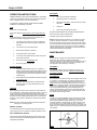
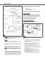
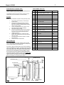
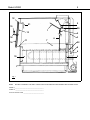
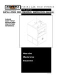
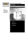
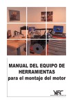
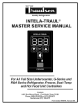
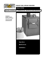
SOLID FUEL SPACE HEATER
Box 3637, Smithers, BC V0J 2N0
Model HF85R
INSTALLATION AND OPERATION INSTRUCTION MANUAL
PLEASE
KEEP THESE
INSTRUCTIONS
FOR FUTURE
REFERENCE
Operation
Maintenance
Installation
DEAR CUSTOMER:
You have purchased what we feel is possibly the best wood burning heating system in North America today!
You will find that your ARDENT ENERGY heater will operate much differently than the old fashioned fire boxes of the
past, offering vastly reduced creosote deposits and an extended burn time.
It is in your best interest to become familiar with your ARDENT ENERGY heating system. Study your Installation
Manual carefully before attempting to install your heating system. Avoid discarding your Installation Manual, as it may
be used for future reference.
In the event you wish to add optional equipment to your unit at a later date, please inform your ARDENT ENERGY
dealer. The serial number of your heater should be included with your order to assure prompt and accurate service.
We congratulate you on your choice of the ARDENT ENERGY heating system and may your home fires keep burning!
Yours truly,
ARDENT ENERGY Inc
J G (Hans) Duerichen P. Eng.
President
June 2001 (ver 3)
TABLE OF CONTENTS
SAFETY INSTRUCTIONS
GENERAL SPECIFICATIONS
OPERATION INSTRUCTIONS
Fuel
The bypass damper
Lighting
Reloading
MAINTENANCE
Ash removal
Door
Draft control
Brick
Exterior
Hot water system
INSTALLATION
Location and clearances
Installation procedure
Connection to chimney
Chimney
Chimney termination
INSTALLATION OF OPTIONS
Wall thermostat kit
Water heating system
Air circulation blower
REPLACEMENT PARTS LIST
REPLACEMENT PARTS ILLUSTRATION
WARRANTY
PAGE
PAGE
PAGE
PAGE
PAGE
PAGE
PAGE
PAGE
PAGE
PAGE
PAGE
PAGE
PAGE
PAGE
PAGE
PAGE
PAGE
PAGE
PAGE
PAGE
PAGE
PAGE
PAGE
PAGE
PAGE
PAGE
PAGE
3
3
4
4
4
4
4
4
4
4
5
5
5
5
5
5
5
5
6
6
6
6
7
7
7
8
9
Model HF85R
3
SAFETY INSTRUCTIONS
GENERAL SPECIFICATIONS
WARNING !
THESE OPERATOR SAFETY INSTRUCTIONS SHOULD BE
TYPE OF FUEL
Wood, any species
COMBUSTION SYSTEM
Down-feed progressive crossdraft design with a constant
preheat secondary air system.
TEMPERATURE CONTROL
Manual bimetallic thermostat
with optional electric wall
thermostat
FIREBOX LINING
Firebrick 32 mm X 114 mm X
229 mm (1 1/4” X 4 1/2” X 9” )
BODY
2.6 mm, 3.5 mm & 8 mm Steel
(12 GA, 10 GA & 5/16” Steel)
DOORS
Constant center push design
with 5/8” (15 7/8 mm) diameter
glass fiber rope seal.
ASH REMOVAL
Approximately every 1-3
months as needed.
READ CAREFULLY!
DO NOT DESTROY
PLEASE RETAIN FOR FUTURE REFERENCE
1.
Fire door must be latched shut at all times when fire is
burning. Open only to reload or check fire.
2.
When reloading or checking fire, pull open bypass lever
first, then open door very slowly.
3.
All combustible material, including firewood, must be a
minimum of 460 mm (l8”) from unit.
4.
Do not hang any combustible material above unit.
5.
Burn wood only!
6.
Do not use gasoline type lantern fuel, kerosene, charcoal
lighter fluid or similar liquids to start or freshen up a fire in
this heater. Keep all such liquids well away from the heater
while it is in use.
•
•
OPTIONS
•
Wall thermostat
Domestic hot water
heating coils
Air circulation blower
Chimney Fires
When wood heats up, wood gases and water vapor
are given off. If these gases are not burned off in the
stove, they condense in the stove pipes and chimney. This buildup is called creosote. This usually happens when a heater is at low heat setting. At high
heat settings most of the gases are burned.
INSULATION
SMOKE SHIELD
BYPASS
DAMPER
FLAME
DEFLECTOR
DOWN DRAFT
BAFFLE
A chimney fire occurs when creosote in the chimney
ignites, usually when the heater is turned up high
after a period of low burn.
CROSS-DRAFT
ANGLE
SECONDARY
HEAT
EXCHANGER
Check your chimney pipe daily for creosote buildup
until experience shows how often cleaning is necessary. Running the heater wide open with bypass
pulled out for 30 minutes periodically (about once a
week) will minimize creosote buildup. If creosote
buildup is 6 mm (1/4”) or more, clean or have the
chimney cleaned mechanically.
PRIMARY HEAT
EXCHANGER
AIR INLET
In the event of an uncontrolled chimney fire, shut the
bypass damper and turn down the draft damper completely. (On thermostat models—turn down thermostat).
If chimney fire does not die down, keep a watch on
fire and prepare to vacate the house.
OPTIONAL
WATER COIL
BLOWER
FIG. 1
FIREBRICK
If needed, call the fire department.
RATING
1,300 - 22,000
5,000 - 85,000
NOTE:
1.
(KW)
(BTU/hr)
SIZE
(mm)
(in.)
692 x 1016 x 965 H
27 ½ x 40 x 38 H
WEIGHT
(Kg)
(lbs.)
273
600
FUEL CAPACITY
(liters)
(cubic ft)
230
8½
MAX. FUEL SIZE
(mm)
(in.)
305 diameter x 610 long
12 diameter x 24 long
FLUE OUTLET
(mm)
(in.)
203 diameter
8 diameter
2.
Establish a routine for the storage of fuel, care of
wood burner and firing technique. Be aware that during mild weather and low heater temperatures, more
creosote is deposited and more frequent cleanings
are necessitated.
All ARDENT ENERGY heating units are designed
with double walled sides and insulated doors. This
keeps the exterior of the units relatively cool. However, children must be taught to respect all wood
burning appliances and not to play around or with
them.
Model HF85R
OPERATION INSTRUCTIONS
ARDENT ENERGY units are especially designed for controllability. With the optional thermostat kit, your house will be heated to
within 1 degree Celsius of your thermostat setting.
The following operating instruction MUST BE FOLLOWED
CAREFULLY for satisfactory operation.
FUEL
Do not burn any fuel but wood.
Do not burn driftwood. Salt corrosion is not covered under warranty.
Wood should be dry, however green wood can be burned. It
should be noted when using green wood that:
1.
The amount of wood that you need is increased by
approximately 20% when using green compared to
dry wood.
2.
The wood has to be in smaller pieces.
3.
More frequent fueling is necessary.
4.
Creosote formation may increase.
5.
The fire has to be started with dry wood until a good
bed of coals is formed.
6.
Heat output will be considerably lower.
7.
Do not use grate or elevate fire.
BYPASS DAMPER
1.
When the bypass damper is open (i.e. bypass rod
pulled out) combustion will take place within the entire
firebox. Operate the heating unit with bypass control
rod pulled out when quick heat is required and when
starting the fire.
2.
When desired house temperature has been achieved
push bypass rod in.
3.
Whenever there is a fire burning, the bypass lever
should be open for 30 seconds before the door is
slowly opened.
LIGHTING
Before lighting, the bottom of the unit must be covered with one
inch of sand or ash. After lighting, leave the door open a crack for
a few minutes for the wood to catch then latch door shut. The
bypass should be left open long enough to allow the chimney and
the heater to reach operating temperature and so create a good
draft. Do not use a grate or elevated fire; build wood fire directly
on hearth.
NOTE: Fire door must be latched shut at all times except when
loading fuel or checking the fire.
MANUAL CONTROL
4
RELOADING
1.
Have wood on hand to load firebox.
2.
Open bypass lever for 30 seconds.
3.
Open the door SLOWLY. Allow the chimney to draw
off smoke
4.
Load wood.
5.
Close door and push bypass lever in.
DO NOT OVER-FIRE UNIT BY LEAVING DOOR OPEN EXCEPT TO LIGHT AND TO CHECK FIRE.
Operation with door ajar voids warranty.
NOTE: Cleanest burning conditions occur when the fuel wood
has been reduced to charcoal. To minimize creosote buildup,
load the unit with just enough wood to last until the next loading
time. This will ensure that the fuel is in charcoal form for a good
portion of the burn cycle. Of course, the unit can be loaded to
capacity during extremely cold weather or when extended intervals between loadings are anticipated.
MAINTENANCE
DAILY
Check chimney and pipe for creosote build-up until experience
shows how often cleaning is necessary. Periodically
(about once week) run unit at maximum with bypass open for 30
minutes to bake any creosote in the chimney and pipes. This
should greatly reduce frequency of cleaning.
AS NEEDED
Any creosote buildup in chimney and pipe over 6 mm (1/4”)
should be removed mechanically. OPEN BYPASS BEFORE
CLEANING CHIMNEY.
ASH REMOVAL
Ashes should be removed once they reach a depth of 100 mm (4
in.) maximum. Let the fire burn out. Protect the area in front of
heater with a non-combustible material. Shovel ashes into a
metal container with a tight fitting lid and leave an inch of ash in
the heater. The closed container of ashes should be placed outside on non-combustible surface, or on the ground, well away
from all combustible materials, pending final disposal. If the
ashes are disposed of by burial in soil or otherwise locally dispersed, they should be retained in the closed container until all
the cinders have thoroughly cooled.
DOOR
The door is an unique adjustable center push design to ensure
trouble free, air tight operation for years to come. When closing
the door there should be a slight resistance; if not, the door
should be adjusted. To adjust in and out, loosen the top 2 nuts,
move the door in or out, then tighten the nuts. To adjust up or
down, loosen the bottom 2 nuts, move the door up or down, then
tighten the nuts. Lubricate door pawl with high temperature lubricant monthly.
Turn manual draft control counterclockwise (open) all the way
until unit warms up, then clockwise to adjust temperature to suit.
TOP
NUTS
WALL THERMOSTAT CONTROL
Set the thermostat at temperature desired. When warming up a
cold room there will be an initial temperature overrun, then the
temperature will stabilize.
BOTTOM
NUTS
FIG. 2
Model HF85R
5
DRAFT CONTROL
Check that it opens and closes freely.
FIREBRICK
Care should be taken when refueling to avoid breakage of brick.
If frozen wood is burned, do not let frozen surface touch brick.
Broken brick must be replaced to prevent overheating of firebox.
Periodically check the door seal for condition and tightness of
door fit. If seal shows signs of a deteriorating condition, improper
fit or signs of leakage, it should be replaced.
FIG. 3
3.
PAINT
The midnight brown, high temperature paint is designed to withstand temperatures to 6500C (12000F). However, should paint
discoloration happen, the affected areas can be retouched. For
the correct type of paint, contact your dealer. When first using the
unit, the paint may smoke for 1/2 hour to 1 hour. This is normal
and is part of the curing process.
4.
5.
HOT WATER SYSTEM
DRAINING AND CLEANING
6.
Cleaning should not normally be necessary unless water tends to
cause deposits. Should heating efficiency drop off noticeably, the
coil in the heater should be inspected and if necessary, cleaned.
7.
8.
Suggested Procedure for Cleaning Coil (see Fig. 6 on Page 7):
1.
2.
3.
4.
5.
6.
Let the unit cool down.
Close the valves to the Range Boiler from the coil.
Open the drain valve & drain water from the coil.
Disconnect the piping & unions.
Clean the coil, using a drain cleaning “snake.”
Connect piping, close drain and open valves to range boiler.
WHEN YOU HAVE NO WATER
Your heater should not be fired with a dry water coil. If you have
no water for circulation, the coil should be isolated from the system and removed, replacing open holes with two 25 mm (1”) diameter standard washers per hole, using a 19 mm x 25 mm (3/4”
X 1”) bolt to hold washers together.
INSTALLATION
9.
To ensure vertical alignment, suspend a plumb bob from
the ceiling over the exact center of the flue of the stove,
and mark a spot on the ceiling to indicate the center of the
chimney.
Check that the intended location will not interfere with ceiling joists or rafters before proceeding further.
Install chimney according to chimney manufacturer’s instructions. Read section on Chimney and see Diagram 2.
Chimney must be a 8” diameter listed chimney suitable for
wood burning appliances. If an existing masonry chimney
is to be used read section under Chimney for specific cautions.
Ceiling shield S85 must be installed on ceilings less than
2.4 m (94”) high. Install shield directly over stove and secure to ceiling with screws provided.
Use plumb bob to ensure that the heater flue is centered
under the chimney.
Install chimney connector. The connector must be at least
24 gauge steel. Insert crimped end of the 8” diameter connector into the heater flue. Install additional connector to
meet chimney.
Connect chimney connector to chimney as per chimney
manufacturer’s instructions.
Combustible floor must be protected by non-combustible material
extending beneath the heater and to the front and sides as indicated: G - 460 mm (18”) ; H - l50 mm (6”) ; 1 - 150 mm (6”)
The space beneath the heater must not be obstructed.
Smoke detector must be located a minimum of 4.5 meters (15’)
away from heating unit to avoid accidentally setting off the smoke
detector.
NOTE: Clearances may be reduced only if combustible material
is protected (See CSA Installation Code for Solid Fuel
Burning Appliances and Equipment No B365—M 1991)
LOCATION AND CLEARANCES
Clearances may be reduced by means approved by the regulatory authority.
MINIMUM CLEARANCE TO COMBUSTIBLE MATERIALS:
CONNECTION TO CHIMNEY
Sidewall (A)
515 mm (20”)
Backwall (B)
305 mm (12”)
Sidewall (D)
700 mm (27½”)
Backwall (E)
395 mm (15½”)
INSTALLATION PROCEDURE
1.
2.
Do not locate near an exit. Do not connect space heater to
any air distribution duct.
Locate heater and floor protection as central as possible
within the home or space to be heated, observing minimum
clearances to combustible materials listed above.
Chimney suitability is the most important factor that will influence
the performance of your ARDENT ENERGY heater. If you follow
these instructions your heater will perform efficiently. If an existing chimney does not meet the specifications consult your ARDENT ENERGY dealer about remedial action.
Unit must be connected to the chimney using a minimum of elbows and horizontal pipe. All horizontal pipe must slope toward
heater and be installed with seam up. Unit flue opening is designed for the connector to go into the opening.
All connections must be such that any condensation in the flue
runs back into the unit and not onto the floor. Ensure connection
pipe is spaced at least 460 mm (18”) from any unprotected combustible material. Do not pass a chimney connector through an
attic or roof space, closet or similar concealed space, or a floor,
ceiling, wall or partition of combustible construction.
Model HF85R
6
regulator should be fitted to the connector pipe. If the draft is less
than .06 appropriate action should be taken to improve the draft.
RAIN CAP
eg.
STORM
COLLAR
915 mm (36”)
MINIMUM
a) insulate chimney
b) move unit to eliminate horizontal section
c) add to top of chimney
If an existing chimney is to be used, it must be inspected carefully
for soundness and to assure that it meets the above specifications.
FLASHING
CEILING SHIELD
8” DIA. LISTED
CHIMNEY
SUITABLE FOR
WOODBURNING
APPLIANCES
TRIM COLLAR
CHIMNEY TERMINATION
Chimneys are required to extend at least 915 mm (3’) above the
highest point where they pass through the roof of the building and
at least 610 mm (2’) higher than any portion within ten feet. In
some cases the chimney must be higher than minimum for enough
draft due to unfavorable geometry of the surroundings.
INSTALLATION OF OPTIONS
WALL THERMOSTAT KIT (MODEL HC2)
8” DIA 24 GA
STEEL
CHIMNEY
CONNECTOR
The control system consists of an electric damper control unit and
a wall thermostat.
LIP INSIDE
FLUE COLLAR
HEAT
DEFLECTOR
MANUAL
CONTROL
FLOOR
SHIELD
WALL THERMOSTAT CONTROL
CHECK REAR
CLEARANCE
THERMOSTAT
CONTROL
HEAT EXCHANGE FINS
WATER COIL
KNOCKOUT
HEAT SHIELD
MOUNTING
SCREW
AIR INLET
ASSEMBLY
FIG. 4
FIG. 5
CAUTION: UNDER NO CIRCUMSTANCES MUST ANY TYPE
OF DAMPER OR RESTRICTION BE INSTALLED IN THE CHIMNEY OR CONNECTING STOVE PIPE.
INSTALLATION
CHIMNEY
1.
Chimney size: 178 mm (8”) diameter or 150 mm x 250 mm (6” x
10”) maximum inside measure masonry chimney.
2.
Metal chimneys must be of a type suitable for wood burning appliances and masonry chimneys must be lined with an approved
liner.
ARDENT ENERGY heating units burn very efficiently, resulting in
lower than usual flue gas temperatures. For this reason,
outside installation of the chimney is not recommended. Due to
the fact that it will dissipate more heat, an outside chimney will
cause more problems with low draft and excessive creosote accumulation.
On initial operation of the heating unit a draft reading should be
taken. (Contact your local ARDENT ENERGY dealer for further
information on measuring draft). The draft should measure .06
water column with the unit at normal operating temperature. If
this reading has to be induced by a roaring fire, it is an indication
that draft is inadequate. If the draft is more than .06 a draft
3.
4.
5.
6.
7.
8.
9.
Remove the 32 mm (1 1/4”) knockout at top left of rear heat
shield. Insert arm through hole and screw the damper control
unit into pre-drilled holes.
Remove left hand side shroud by unscrewing 2 screws at
back.
Attach one end of ball chain to damper control arm.
Attach the remaining end through hole in air intake assembly.
(There should be a slight slack in the chain.)
Locate thermostat some distance from heater 3M - 6M (10’ 20’) but not in another room unless direct venting is provided
for hot air.
The thermostat should be set on an interior wall. Follow manufacturer’s instructions.
The heat anticipator setting should be 0.4 amps.
Check chain length by shutting off the manual control and
setting the thermostat above room temperature. The draft
damper should open to maximum.
Set thermostat below room temperature; the draft damper
should close completely. Adjust chain length if required.
Model HF85R
7
WATER HEATING COIL (MODEL SHW4)
ARDENT ENERGY heating units are designed to heat your domestic hot water during the heating season.
The HF85R can accept one or two coils (1 per side). The coil
replaces all but one of the firebrick on the side located.
Procedure:
REPLACEMENT PARTS LIST
ITEM QTY DESCRIPTION
PART #
1
1
Scandinavian baffle 8 x 18 5/8
AAP016
2
1
Bypass damper
A237W
3
26”
#10 Steel ball chain
R6110
4
2
Detachable pendant 6P
R6121
5
1
Flame deflector
A540
6
1
Down draft baffle
A542
7
2
Cross draft angle
A543W
8
1
Draft control
A913
9
1
Primary air heat exchanger
A321W
10
19
Firebrick 1 1/4 x 4 1/2 x 9
R7101
11
1
Door sill 3 x 16 1/8
AAP059
12
80”
Gasket 5/8 round regular black
R7005
13
1
Door liner
A086
14
1
Door
A356W
15
1
Door knob 1 7/8 OD 1/2 ID
R6020
16
1
Door closer
A759W
17
2
Draft/bypass handle 5/16
R6005
18
1
Bypass bar
A334
19
1
Draft control rod
A324W
20
1
Bypass lever
A239W
21
1
Smoke shield
A079W
22
1
Draft control gasket
A989
NOTE: Ensure installation complies with local plumbing codes.
1.
2.
3.
4.
5.
6.
7.
8.
Remove both side shrouds by unscrewing the
screws at back.
Remove rear heat shield and punch out the 2
knockouts on the side desired. Knock outs are
tight, out of necessity. A sharp blow with a heavy
hammer will be required.
Loosen cross draft angle nuts on side of unit. (2
each side located on outside of firebox).
Remove brick from that side.
Punch out 2 knockouts at back of stove. Reach in
through punched out holes with a bar extension
and punch out knockouts in primary heat exchanger. (see Fig 5.)
Position water coil in stove, replace brick and
tighten cross draft angle nuts on side of heater to
hold coil in place.
Install mineral wool gasket and plate on outside
and screw tight.
Replace shrouds and heat shield.
TANK CONNECTION
It is recommended that the ‘2 tank” system be used. The first
tank or “Range Boiler” must remain un-insulated to dissipate any
excess heat generated by the hot water coil.
Connection of piping to Range Boiler must be strictly followed as
shown in the Diagram. The 2 shut—off valves must be no smaller
than 3/4 inch GATE valves. Make certain that the PRV (Watts 3L)
and P&TRV (Watts 100XL) are installed in their respective locations and not vice versa. Maximum pressure setting is 150 psi.
Do not use less than 3/4 inch diameter standard pipe between
range boiler and heater, orientation of pipe must be slightly uphill
from the coil outlet to the upper connection at the tank, otherwise
vapor lock will occur and water will not circulate. Minimum range
Boiler recommended is 30 Imperial gallon capacity.
FIG. 6
Model HF85R
8
12
2
21
15
20
1
13
5
16
6
11
14
3
7
22
8
4
10
9
Fig. 7
NOTE:
RECORD YOUR MODEL AND SERIAL # HERE FOR EASY REFERENCE WHEN ORDERING REPLACEMENT PARTS.
MODEL # ____________________________________________
SERIAL I# ___________________________________________
DATE OF INSTALLATION _______________________________
Model HF85R
9
Model HF85R Space Heater Warranty
THREE YEAR LIMITED WARRANTY
Ardent Energy Ltd. warrants the Model HF85R space heater against defects in material and workmanship for a period of three (3) years from the date received, with the exception of items listed hereafter
in the "Exclusions" section.
Ardent Energy Ltd., at its option, will replace, repair or cause to be repaired any part found to be
defective upon inspection by an authorized Ardent Energy Ltd. representative.
EXCLUSIONS
1. Repairs or replacement of part or all of the appliance, necessitated by use of the stove other than for
normal home use, as directed by the instruction manual.
2. Repairs or replacements necessitated by vandalism, neglect, abuse or failure to adequately service
the appliance, as stated in the instruction manual.
3. Repairs or replacements necessitated by work or service not authorized by Ardent Energy Ltd.
4. Equipment and accessories not manufactured by Ardent Energy are warranted only to the extent of
the original manufacturer's warranty.
5. Repairs or replacement of motors, fittings, controls, transformers, accessories and so forth.
6. Replacement of gaskets and firebrick.
7. Repairs necessitated by excessive chimney draft.
LIMITATIONS
1. All items found to be defective will be replaced or repaired upon return of the defective part to an authorized Ardent Energy Ltd. dealer.
2. Any space heater or part thereof that is replaced or serviced during the three year warranty period,
will be warranted under the terms of that particular limited warranty for a period not exceeding the remaining term of the original limited warranty, or six months, whichever is longer.
3. This warranty is transferable. However, proof of date of purchase is required before service or replacement of any defective part is performed.
4. This Limited Warranty does not apply to damage to the space heater or part thereof, while in transit.
Any claim of such must be directed to the common carrier.
5. If the installation does not conform to local building or fire codes, or in their absence, the installation
requirements in the instruction manual, any claims are not valid and will not be processed.
6. Any shipping charges incurred during a warranty claim will be borne by the space heater owner.
7. The remedies set forth herein are exclusive, and the liability of Ardent Energy Ltd. with respect to any
contract, tort, under any warranty or otherwise shall not exceed the price of the equipment or part on
which such liability is based.
To enable us to service any warranty claim as quickly as possible, please fill out and return your warranty card as soon as you receive
your Ardent Energy space heater.