1
Agilent E7501A Arbitrary Analog
Signal Development System
(...a component of Signal Studio™)
Getting Started
Part Number: E7501-90001
Printed in USA
November 22, 2000
Notice
The information contained in this document is subject to change without
notice.
Agilent Technologies makes no warranty of any kind with regard to this
material, including, but not limited to, the implied warranties of
merchantability and fitness for a particular purpose. Agilent Technologies
shall not be liable for errors contained herein or for incidental or
consequential damages in connection with the furnishing, performance, or
use of this material.
Agilent Technologies assumes no responsibility for the use or reliability of
its software on equipment that is not furnished by Agilent Technologies.
This document contains proprietary information which is protected by
copyright. All rights are reserved. No part of this document may be
photocopied, reproduced, or translated to another language without prior
written consent of Agilent Technologies.
Restricted Rights Legend
Use, duplication, or disclosure by the U.S. Government is subject to
restrictions as set forth in subparagraph (c)(1)(ii) of the Rights in Technical
Data and Computer Software clause at DFARS 252.227-7013 for DOD
agencies, and subparagraphs (c)(1) and (c)(2) of the Commercial Computer
Software Restricted Rights clause at FAR 52.227-19 for other agencies.
Agilent Technologies
1400 Fountaingrove Parkway
Santa Rosa, CA 95403-1799, U.S.A.
© Copyright Agilent Technologies 2000
Adobe® Acrobat® is a trademark of Adobe Systems Incorporated.
QuickTime™ is a U.S. trademark of Apple Computer, Inc.
Windows NT® is a U.S. registered trademark of Microsoft Corporation.
Notepad and WordPad are products of Microsoft Corporation.
ii Agilent E7501A Getting Started
Warranty
Certification
Agilent Technologies certifies that this product met its published
specifications at the time of shipment from the factory. Agilent Technologies
further certifies that its calibration measurements are traceable to the
United States National Institute of Standards and Technology (NIST,
formerly NBS), to the extent allowed by the Institute’s calibration facility,
and to the calibration facilities of other International Standards
Organization members.
Warranty
This Agilent Technologies system product is warranted against defects in
materials and workmanship for a period corresponding to the individual
warranty periods of its component products. Instruments are warranted for a
period of three years. During the warranty period, Agilent Technologies will,
at its option, either repair or replace products that prove to be defective.
Warranty service for products installed by Agilent Technologies and certain
other products designated by Agilent Technologies will be performed at
Buyer’s facility at no charge within Agilent Technologies service travel
areas. Outside Agilent Technologies service travel areas, warranty service
will be performed at Buyer’s facility only upon Agilent Technologies’s prior
agreement and Buyer shall pay Agilent Technologies’s round trip travel
expenses. In all other areas, products must be returned to a service facility
designated by Agilent Technologies.
For products returned to Agilent Technologies for warranty service, Buyer
shall prepay shipping charges to Agilent Technologies and Agilent
Technologies shall pay shipping charges to return the product to Buyer.
However, Buyer shall pay all shipping charges, duties, and taxes for products
returned to Agilent Technologies from another country.
Agilent Technologies warrants that its software and firmware designated by
Agilent Technologies for use with an instrument will execute its
programming instructions when properly installed on that instrument.
Agilent Technologies does not warrant that the operation of the instrument,
or software, or firmware will be uninterrupted or error free.
Agilent E7501A Getting Started iii
LIMITATION OF WARRANTY. The foregoing warranty shall not apply
to defects resulting from improper or inadequate maintenance by Buyer,
Buyer-supplied software or interfacing, unauthorized modification or
misuse, operation outside of the environmental specifications for the
product, or improper site preparation or maintenance.
NO OTHER WARRANTY IS EXPRESSED OR IMPLIED. AGILENT
TECHNOLOGIES SPECIFICALLY DISCLAIMS THE IMPLIED
WARRANTIES OR MERCHANTABILITY AND FITNESS FOR A
PARTICULAR PURPOSE.
EXCLUSIVE REMEDIES. THE REMEDIES PROVIDED HEREIN ARE
BUYER’S SOLE AND EXCLUSIVE REMEDIES. AGILENT
TECHNOLOGIES SHALL NOT BE LIABLE FOR ANY DIRECT,
INDIRECT, SPECIAL, INCIDENTAL, OR CONSEQUENTIAL
DAMAGES, WHETHER BASED ON CONTRACT, TORT, OR ANY
OTHER LEGAL THEORY.
Assistance
Product maintenance agreements and other customer assistance agreements
are available for Agilent Technologies products.
For assistance, call your local Agilent Technologies Sales and Service Office
(refer to “Service and Support” on page v).
iv Agilent E7501A Getting Started
Service and Support
Any adjustment, maintenance, or repair of this product must be performed
by qualified personnel. Contact your customer engineer through your local
service center. You can find support information on the web at
http://www.tm.agilent.com
If you do not have access to the Internet, one of these Agilent Technologies
centers can direct you to your nearest representative:
United States:
Agilent Technologies
Test and Measurement Call Center
PO Box 4026
Englewood, CO 80155-4026
(800) 452 4844 (toll-free in US)
Canada:
Agilent Technologies Canada Ltd.
5150 Spectrum Way
Mississauga, Ontario L4W 5G1
(905) 206 4725
Europe:
Agilent Technologies European Marketing Centre
Postbox 999
1180 AZ Amstelveen
The Netherlands
(31 20) 547 9900
Japan:
Agilent Technologies Ltd.
Measurement Assistance Center
9-1, Takakura-Cho, Hachioji-Shi
Tokyo 192, Japan
(81) 426 56 7832
(81) 426 56 7840 (FAX)
Latin America:
Agilent Technologies Latin American Region Headquarters
5200 Blue Lagoon Drive, 9th Floor
Miami, Florida 33126, U.S.A.
(305) 267 4245, (305) 267-4220
(305) 267 4288 (FAX)
Australia/New Zealand:
Agilent Technologies Australia Ltd.
31-41 Joseph Street
Blackburn, Victoria 3130
Australia
1 800 629 485 (Australia)
0800 738 378 (New Zealand)
(61 3) 9210 5489 (FAX)
Asia-Pacific:
Agilent Technologies Asia Pacific Ltd.
17-21/F Shell Tower, Times Square
1 Matheson Street, Causeway Bay
Hong Kong
(852) 2599 7777
(852) 2506 9285 (FAX)
Agilent E7501A Getting Started v
Safety and Regulatory Information
Review this product and related documentation to familiarize yourself with
safety markings and instructions before you operate the instrument. This
product has been designed and tested in accordance with international
standards.
WARNING
The WARNING notice denotes a hazard. It calls attention to a procedure,
practice, or the like, that, if not correctly performed or adhered to, could result
in personal injury. Do not proceed beyond a WARNING notice until the
indicated conditions are fully understood and met.
CAUTION
The CAUTION notice denotes a hazard. It calls attention to an operating
procedure, practice, or the like, which, if not correctly performed or adhered
to, could result in damage to the product or loss of important data. Do not
proceed beyond a CAUTION notice until the indicated conditions are fully
understood and met.
Instrument Markings
!
When you see this symbol on your instrument, you should refer to the instrument’s
instruction manual for important information.
This symbol indicates hazardous voltages.
The laser radiation symbol is marked on products that have a laser output.
This symbol indicates that the instrument requires alternating current (ac) input.
The CE mark is a registered trademark of the European Community. If it is
accompanied by a year, it indicates the year the design was proven.
The CSA mark is a registered trademark of the Canadian Standards Association.
1SM1-A
This text indicates that the instrument is an Industrial Scientific and Medical Group 1
Class A product (CISPR 11, Clause 4).
This symbol indicates that the power line switch is ON.
This symbol indicates that the power line switch is OFF or in STANDBY position.
vi Agilent E7501A Getting Started
Safety Earth
Ground
This is a Safety Class I product (provided with a protective earthing
terminal). An uninterruptible safety earth ground must be provided from the
main power source to the product input wiring terminals, power cord, or
supplied power cord set. Whenever it is likely that the protection has been
impaired, the product must be made inoperative and secured against any
unintended operation.
Before Applying Power
Verify that the product is configured to match the available main power
source as described in the input power configuration instructions in this
manual. If this product is to be powered by autotransformer, make sure the
common terminal is connected to the neutral (grounded) side of the ac power
supply.
Agilent E7501A Getting Started vii
Typeface Conventions
•
Used to emphasize important information:
Use this software only with the Agilent Technologies xxxxxX
system.
•
Used for the title of a publication:
Refer to the Agilent Technologies xxxxxX System-Level User’s
Guide.
•
Used to indicate a variable:
Type LOAD BIN filename.
Instrument Display
•
Used to show on-screen prompts and messages that you will see on the
display of an instrument:
The Agilent Technologies xxxxxX will display the message CAL1
SAVED.
[Keycap]
•
Used for labeled keys on the front panel of an instrument or on a
computer keyboard:
Press [Return].
{Softkey}
•
Used for simulated keys that appear on an instrument display:
Press {Prior Menu}.
User Entry
•
Used to indicate text that you will enter using the computer keyboard;
text shown in this typeface must be typed exactly as printed:
Type LOAD PARMFILE
•
Used for examples of programming code:
Italics
#endif // ifndef NO_CLASS
Path Name
•
Used for a subdirectory name or file path:
Edit the file usr/local/bin/sample.txt
Computer Display
•
Used to show messages, prompts, and window labels that appear on a
computer monitor:
The Edit Parameters window will appear on the screen.
•
Used for menus, lists, dialog boxes, and button boxes on a computer
monitor from which you make selections using the mouse or keyboard:
Double-click EXIT to quit the program.
viii Agilent E7501A Getting Started
In This Book...
In this book, you will learn about:
•
•
•
•
Installation of Hardware and Software
Performing Manual Acceptance Tests
Using SCPI Interfaces
Specifications and Characteristics
This book prepares you for your first steps in using the Agilent E7501A
arbitrary analog signal developer.
The standard Agilent E7501A arbitrary analog signal developer forms a
frequency source and consists of a microwave synthesizer coupled with a
three-channel arbitrary waveform generator (ARB) for generating AM, FM,
and Pulse drive signals. The frequency source is implemented in a C-size,
VXI mainframe that occupies four to six slots; the actual number of slots
depends on the Slot 0 module being used.
Agilent E7501A arbitrary analog signal developer software is used to
produce signals with AM, FM, and Pulse modulations and save all
information about the signal in what is referred to as a Signal Plan. You can
use the features of this software through its main GUI or through a
remote-programming interface. The way that the main GUI is used is
dependent on the view that you select. There are currently three views
available: RF Source Control View, Stimulus Parameters View, or
Signal Plan View. While all views give you access to information used in a
Signal Plan, there is a difference in the way in which information is accessed
and displayed. In addition, each view gives you access to different sets of
parameters in a Signal Plan. When using the software through a
remote-programming interface, you control the software by the use of SCPI
commands that are sent through either the E7501A SCPI Interface, the
E7501A SCPI Assistant, a LAN interface, or a GPIB interface.
Agilent E7501A Getting Started ix
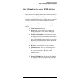
How to proceed…
First, review the hardware and software requirements for using this
product. After installing the Agilent E7501A arbitrary analog signal
developer software, start the program and become familiar with the
features available on the main GUI, various pull-down menus, dialog
boxes, and the various views available.
This software is used to produce signals with AM, FM, and Pulse
modulations and save all information about the signal in what is referred
to as a Signal Plan. A Signal Plan is a detailed description of a signal
which is used to generate physical signals in a hardware independent
manner.
If you have your hardware assets available, you can learn about
preparing the software to work with your hardware. Finally, you can
learn about producing signals and developing a Signal Plan by working
through the main GUI or a SCPI interface.
x Agilent E7501A Getting Started
Contents
Notice . . . . . . . . . . . . . . . . . . . . . . . . . . . . . . . . . . . . . . . . . . . . . . . . . . . . . ii
In This Book... . . . . . . . . . . . . . . . . . . . . . . . . . . . . . . . . . . . . . . . . . . . . . . ix
1.
Installation and Configuration
Hardware and Software Requirements . . . . . . . . . . . . . . . . . . . . . . . . . . . 1-2
Step 1. Unpacking the Agilent E7501A System . . . . . . . . . . . . . . . . . . . . 1-3
Step 2. Installing the System Hardware . . . . . . . . . . . . . . . . . . . . . . . . . . 1-4
Step 3. Installing the Agilent E7501A Software . . . . . . . . . . . . . . . . . . . . 1-7
Step 4. Configuring Hardware/Software Assets . . . . . . . . . . . . . . . . . . . 1-10
Understanding the Asset Manager . . . . . . . . . . . . . . . . . . . . . . . . . . 1-10
Starting the Asset Manager . . . . . . . . . . . . . . . . . . . . . . . . . . . . . . . 1-11
Selecting a Configuration . . . . . . . . . . . . . . . . . . . . . . . . . . . . . . . . . 1-12
Configuring an RF Source . . . . . . . . . . . . . . . . . . . . . . . . . . . . . . . . 1-13
Configuring a Modulation Source . . . . . . . . . . . . . . . . . . . . . . . . . . 1-15
(Optional) Configuring Other Available Assets . . . . . . . . . . . . . . . . 1-16
(Optional) Adding a Hardware/Software Asset . . . . . . . . . . . . . . . . 1-17
(Optional) Removing a Hardware/Software Asset . . . . . . . . . . . . . . 1-19
Exiting Configuration . . . . . . . . . . . . . . . . . . . . . . . . . . . . . . . . . . . . 1-19
Step 5. Starting the Agilent E7501A Software . . . . . . . . . . . . . . . . . . . . 1-20
2.
Performing Acceptance Test Procedures
Test 1. CW Frequency and Power . . . . . . . . . . . . . . . . . . . . . . . . . . . . . . 2-2
Description . . . . . . . . . . . . . . . . . . . . . . . . . . . . . . . . . . . . . . . . . . . . . 2-2
Equipment Required . . . . . . . . . . . . . . . . . . . . . . . . . . . . . . . . . . . . . . 2-2
Equipment Setup . . . . . . . . . . . . . . . . . . . . . . . . . . . . . . . . . . . . . . . . 2-2
Test 2. AM Accuracy . . . . . . . . . . . . . . . . . . . . . . . . . . . . . . . . . . . . . . . . 2-5
Description . . . . . . . . . . . . . . . . . . . . . . . . . . . . . . . . . . . . . . . . . . . . . 2-5
Equipment Required . . . . . . . . . . . . . . . . . . . . . . . . . . . . . . . . . . . . . . 2-5
Equipment Setup . . . . . . . . . . . . . . . . . . . . . . . . . . . . . . . . . . . . . . . . 2-5
Test 3. FM Accuracy . . . . . . . . . . . . . . . . . . . . . . . . . . . . . . . . . . . . . . . . 2-8
Description . . . . . . . . . . . . . . . . . . . . . . . . . . . . . . . . . . . . . . . . . . . . . 2-8
Equipment Required . . . . . . . . . . . . . . . . . . . . . . . . . . . . . . . . . . . . . . 2-8
Equipment Setup . . . . . . . . . . . . . . . . . . . . . . . . . . . . . . . . . . . . . . . . 2-8
Test 4. Pulse Modulation Level Accuracy . . . . . . . . . . . . . . . . . . . . . . . 2-11
Description . . . . . . . . . . . . . . . . . . . . . . . . . . . . . . . . . . . . . . . . . . . . 2-11
Equipment Required . . . . . . . . . . . . . . . . . . . . . . . . . . . . . . . . . . . . . 2-11
Equipment Setup . . . . . . . . . . . . . . . . . . . . . . . . . . . . . . . . . . . . . . . 2-11
Test 5. Verify Hopping
with Two Pulse Modulated Signals . . . . . . . . . . . . . . . . . . . . . . . . . 2-14
Description . . . . . . . . . . . . . . . . . . . . . . . . . . . . . . . . . . . . . . . . . . . . 2-14
Equipment Required . . . . . . . . . . . . . . . . . . . . . . . . . . . . . . . . . . . . . 2-14
Equipment Setup . . . . . . . . . . . . . . . . . . . . . . . . . . . . . . . . . . . . . . . 2-14
Agilent E7501A Getting Started Contents-11
Test 6. Verify Synchronization of the Racal 3153 . . . . . . . . . . . . . . . . . 2-16
Description . . . . . . . . . . . . . . . . . . . . . . . . . . . . . . . . . . . . . . . . . . . . 2-16
Equipment Required . . . . . . . . . . . . . . . . . . . . . . . . . . . . . . . . . . . . . 2-16
3.
Using SCPI Interfaces
Overview of SCPI Interfaces . . . . . . . . . . . . . . . . . . . . . . . . . . . . . . . . . .
E7501A SCPI Assistant . . . . . . . . . . . . . . . . . . . . . . . . . . . . . . . . . . .
E7501A SCPI Interface . . . . . . . . . . . . . . . . . . . . . . . . . . . . . . . . . . .
Using the E7501A SCPI Assistant . . . . . . . . . . . . . . . . . . . . . . . . . . . . . .
To Start the E7501A SCPI Assistant . . . . . . . . . . . . . . . . . . . . . . . . .
E7501A SCPI Assistant GUI . . . . . . . . . . . . . . . . . . . . . . . . . . . . . . .
SCPI Assistant SCPI Command Entry Box . . . . . . . . . . . . . . . . . . . .
SCPI Assistant Quick Reference Guide Selection Box . . . . . . . . . . .
SCPI Assistant Query Response Box . . . . . . . . . . . . . . . . . . . . . . . . .
SCPI Assistant Indicators and Related Functions . . . . . . . . . . . . . . .
Using the E7501A SCPI Interface . . . . . . . . . . . . . . . . . . . . . . . . . . . . . .
Understanding the E7501A SCPI Interface . . . . . . . . . . . . . . . . . . . .
Making a Connection . . . . . . . . . . . . . . . . . . . . . . . . . . . . . . . . . . . . .
Configuring a VXI-11 Connection . . . . . . . . . . . . . . . . . . . . . . . . . . .
Examples Using HPBW and VXI-11 . . . . . . . . . . . . . . . . . . . . . . . . .
Configuring a Telnet, Sockets, or RS-232 Connection . . . . . . . . . . .
Examples Using a Telnet Connection . . . . . . . . . . . . . . . . . . . . . . . .
Starting the E7501A SCPI Interface Programmatically . . . . . . . . . . . . . .
4.
18
18
18
19
20
21
22
22
23
24
27
27
28
29
39
40
44
50
Specifications and Characteristics
Agilent E7501A Getting Started Contents-12
1
Installation and Configuration
Preconfigured System
A preconfigured system
includes a computer shipped
from Agilent Technologies with
all required hardware and
software pre installed.
This chapter helps guide you though the process of installing both the
hardware (if you did not order a preconfigured system) and the Agilent
E7501A arbitrary analog signal developer software. A set of acceptance tests
are also included at the end of this installation process. The acceptance tests
are intended as functionality checks and are not intended for testing against
customer specifications.
If You Ordered
...Preconfigured System, perform the following steps:
...Option 1FF (delete computer), perform the following steps:
Skip “Hardware and Software Requirements” on page 1-2
Confirm that your system meets all
“Hardware and Software Requirements” on page 1-2
“Step 1. Unpacking the Agilent E7501A System” on page 1-3
“Step 1. Unpacking the Agilent E7501A System” on page 1-3
Skip Steps 2 to 4
“Step 2. Installing the System Hardware” on page 1-4
“Step 3. Installing the Agilent E7501A Software” on page 1-7
“Step 4. Configuring Hardware/Software Assets” on page 1-10
“Step 5. Starting the Agilent E7501A Software” on page 1-20
“Step 5. Starting the Agilent E7501A Software” on page 1-20
“Performing Acceptance Test Procedures” on page 2-1
“Performing Acceptance Test Procedures” on page 2-1
Agilent E7501A Getting Started 1-1
Installation and Configuration
Hardware and Software Requirements
Hardware and Software Requirements
•
•
•
•
•
•
Pentium microprocessor (400 MHz or higher recommended)
•
One of the following Slot 0 modules:
Windows NT 4.0 with Service Pack 5 or higher
Minimum of 128 MB of RAM or higher
Minimum of 1 GB hard disk space or higher
CD-ROM drive
Agilent E8403A C-size VXI mainframe or equivalent with five or six
empty slots (the number of slots is dependent on the Slot 0 module used)
Agilent E8491B IEEE-1394 PC Link to VXI - Using a PCI to
IEEE-1394 Interface
Agilent 9850A VXI Embedded PC Controller or equivalent
Agilent I/O Libraries Version J.01.02 or higher (which contains
Agilent Technologies VISA)
Agilent External CD-ROM drive and its interface cable
NI VXI-MXI-2 - Using a PCI-MXI-2 Interface
NOTE
Agilent I/O Libraries Version J.01.02 or higher (which contains
Agilent Technologies VISA)
National Instruments VISA I/O Library Version 2.0 or higher
Agilent E7501A arbitrary analog signal developer is not compatible with
National Instruments MXI-1 or GPIB interfaces, or an Agilent 82341A
GPIB interface card or its equivalent.
1-2 Agilent E7501A Getting Started
Installation and Configuration
Step 1. Unpacking the Agilent E7501A System
Step 1. Unpacking the Agilent E7501A System
1. Unpack and inspect the shipping container and its contents thoroughly to
ensure that nothing was damaged during shipment.
If the container or packing material is damaged, the contents should be
checked both mechanically and electrically. If the contents are damaged
or defective, contact your nearest Agilent Technologies Sales and
Service office. Keep the shipping materials for the carrier’s inspection.
Verify that all parts and materials were included in the shipping
container:
•
•
Getting Started - this document
•
Parallel Port License Key- contains a hardware license
key (dongle) that attaches to the parallel printer port on the
rear of your PC and is used to validate a use license; if you
order a VXI Embedded PC, the license key is connected to
the parallel printer port through an interface adapter cable
that is supplied with the PC.
•
•
•
•
VXI Mainframe - Agilent E8403A C-size mainframe
•
External CD-ROM Drive - this external CD-ROM drive
and its interface cable is only supplied when your system
uses a VXI Embedded PC controller as the Slot 0 module
Software CD - contains all software components for
installing the Agilent E7501A arbitrary analog signal
development system
RF Source - Agilent E6432A microwave synthesizer
Modulation Source - Racal 3153 waveform generator
Three Cables - for connecting AM, FM, and Pulse input
and output ports between the RF source and the
modulation source
Agilent E7501A Getting Started 1-3
Installation and Configuration
Step 2. Installing the System Hardware
Step 2. Installing the System Hardware
NOTE
If you ordered a preconfigured system, skip this step and proceed to
“Step 5. Starting the Agilent E7501A Software” on page 1-20.
CAUTION
Do not turn power on to the C-size VXI mainframe until all VXI modules
have been installed and you have made all peripheral connections to the
Slot 0 module being used.
If you have problems or questions reqarding the following processes, refer to
the manufacturers’ documentation for the product in question.
1. Set up an Agilent Technologies E8403A C-size VXI mainframe or
equivalent.
2. Turn power off to the C-size VXI mainframe and install the Slot 0
module being used.
3. Set the logical addresses of the Agilent Technologies E6432A
microwave synthesizer and Racal 3153 waveform generator:
The units can be Auto Configured when set to address 255 (FF).
If you prefer to manually select the addresses, the factory suggests
using address 210 (D2) for the Agilent Technologies E6432A
microwave synthesizer and 3 for the Racal 3153 waveform
generator.
4. Install the Agilent Technologies E6432A microwave synthesizer and
Racal 3153 waveform generator into the C-size VXI mainframe.
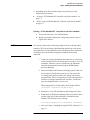
5. Connect the front panel cables as follows:
Agilent Technologies E6432A
Racal 3153
Pulse
Output 1
FM
Output 2
AM
Output 3
10 MHz Out 0 dBm
10 MHz REF INPUT
1-4 Agilent E7501A Getting Started
Installation and Configuration
Step 2. Installing the System Hardware
6. Depending on the Slot 0 module being used, perform one of the
following two procedures:
“If using a VXI Embedded PC Controller as the Slot 0 module:” on
page 1-5
“If NOT using a VXI Embedded PC Controller as the Slot 0 module:”
on page 1-6
If using a VXI Embedded PC Controller as the Slot 0 module:
a. Turn power ON to the C-size VXI mainframe.
b. Run the pre-installed Agilent I/O Config utility (which is part of
Agilent I/O Libraries).
CAUTION
Use extreme caution when connecting peripheral cables to the embedded
controller. The I/O base board of the embedded controller provides power
for peripheral devices through different pins. Making incorrect connections
can damage the board and may damage the peripheral device being
connected.
i.
Connect any desired peripherals (keyboard, mouse, serial ports,
monitor, and SCSI devices) and turn power on to the C-size VXI
mainframe. When the system is powered on, the embedded
controller automatically runs the program SURM [Startup
Resource Manager].
ii. Before the Windows NT software (including Agilent VISA) can
be used, the I/O Config utility must be run. You can run the
I/O Config utility that is located in the Agilent I/O Libraries
program folder. The I/O Config utility is used by the Agilent I/O
Libraries to configure instrument I/O interfaces. An interface
must be configured before it can be used.
While running the I/O Config utility, check the box labeled,
“Configure interfaces automatically”.
iii. Reboot the C-size VXI mainframe so that changes take effect.
iv. Run Resman [VXI Resource Manager] and verify that the Slot 0
module being used is found. Resman is available from the
Windows NT Start task bar by selecting:
Start/Programs/National Instruments VXI/Resman
v. Proceed to “Step 3. Installing the Agilent E7501A Software” on
page 1-7.
Agilent E7501A Getting Started 1-5
Installation and Configuration
Step 2. Installing the System Hardware
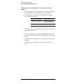
If NOT using a VXI Embedded PC Controller as the Slot 0
module:
a. Set up a Windows NT computer with Service Pack 5 or higher that
has a CD-ROM drive and a minimum of 128 MB or RAM.
b. Turn power OFF to the Windows NT computer and install the
PCI interface card being used.
PCI Interface Card Being Used
Slot 0 Module Being Used
PCI to IEEE-1394 Interface
Agilent Technologies E8491B
IEEE-1394 PC Link to VXI
PCI-MXI-2 Interface
National Instruments VXI-MXI-2
c. Connect the interface cable between the PCI interface card and the
Slot 0 module being used.
When connecting between an Agilent E8491B Slot 0 module and
the PCI to IEEE-1394 interface, any available IEEE-1394 port may
be used.
d. Turn power ON to the Windows NT computer and the C-size VXI
mainframe.
e. Proceed to “Step 3. Installing the Agilent E7501A Software” on
page 1-7.
1-6 Agilent E7501A Getting Started
Installation and Configuration
Step 3. Installing the Agilent E7501A Software
Step 3. Installing the Agilent E7501A Software
NOTE
If you ordered a preconfigured system, skip this step and proceed to
“Step 5. Starting the Agilent E7501A Software” on page 1-20.
1. Insert the Agilent E7501A arbitrary analog signal developer CD-ROM.
If the CD does not auto install, the Setup.exe file can be executed
from the Windows NT Start task bar by selecting:
Start/Run and typing D:\Setup.exe (where D:\ is the path to the
CD-ROM drive).
The following is performed
during the installation
process:
2. The version of the operating system is checked to assure
Windows NT 4.0 is installed.
If Windows NT 4.0 is not found, a message is displayed and the
installation process is aborted.
3. The computer is checked to assure that a minimum of 128 MB of RAM
is installed.
If there is not 128 MB or more of RAM available, a message is
displayed informing the user that the software will run slow, but the
installation process can still continue.
4. The version of the Service Pack is checked to assure Service Pack 5 or
greater is installed.
If Service Pack 5 or greater is not installed, a dialog box is displayed
allowing the Service Pack to be upgraded.
If you answer “no” to the dialog box, a message is displayed and
the software installation process is aborted.
If you answer “yes” to the dialog box, the software installation
process is aborted and a Service Pack installation is run. After
the Service Pack upgrade is complete, the software installation
process must be restarted from step 1 of this procedure.
The user is prompted to select a Slot 0 module for I/O
communication or to install the software to run in
Demonstration Mode (Demo Mode).
Agilent E7501A Getting Started 1-7
Installation and Configuration
Step 3. Installing the Agilent E7501A Software
Use Demo Mode or select a
Slot 0 Module
•
If Demonstration Mode is selected, no I/O libraries are required and the
Agilent E7501A arbitrary analog signal developer software can be used
without hardware.
If You Select a
Slot 0 Module
•
If Slot 0 is selected to be an Agilent E8491B IEEE-1394 PC Link to
VXI, the Agilent I/O Libraries are installed.
During the installation of Agilent I/O Libraries (which contains
Agilent VISA):
a. Check the box labeled,
“Install Agilent E8491 VXI Components”.
This installs code for the PCI to IEEE-1394 interface card.
b. Check the box labeled
“Configure interfaces automatically”.
(If this box is not checked, you must manually configure the PCI to
IEEE-1394 interface card using the I/O Config utility before it can
be used with the Agilent I/O Libraries. The I/O Config utility is used
by the Agilent I/O Libraries to configure instrument I/O interfaces.
An interface must be configured with the I/O Config utility before it
can be used with the Agilent I/O Libraries. For further information
on using the I/O Config utility, refer to the documentation that came
with the PCI to IEEE-1394 interface card.)
•
If Slot 0 is selected to be a National Instruments VXI-MXI-2, the
National Instruments VISA Library is installed.
The following steps must be performed after the installation of the
National Instruments VISA Library:
a. Run the program T&M Explorer [Test and Measurement Explorer].
T&M Explorer is available from the Windows NT Start task bar by
selecting:
Start/Programs/National Instruments VXI/T&M Explorer.
b. Select the PCI-MXI-2 interface.
c. Right-mouse click and select Hardware Configuration.
d. Select the PCI tab and select the checkbox labeled:
Enable low-level register access API support.
e. Select the down arrow on the User window size entry box, select
8 MB, and select OK.
f.
Exit T&M Explorer.
1-8 Agilent E7501A Getting Started
Installation and Configuration
Step 3. Installing the Agilent E7501A Software
g. Reboot the Windows NT computer and VXI mainframe so that
changes take effect.
h. Run the program Resman [VXI Resource Manager] and verify that
the Slot 0 module being used is found.
Resman is available from the Windows NT Start task bar by
selecting:
Start/Programs/National Instruments VXI/Resman.
Agilent E7501A Getting Started 1-9
Installation and Configuration
Step 4. Configuring Hardware/Software Assets
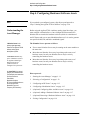
Step 4. Configuring Hardware/Software Assets
NOTE
If you ordered a preconfigured system, skip this step and proceed to
“Step 5. Starting the Agilent E7501A Software” on page 1-20.
Understanding the
Asset Manager
Before using the Agilent E7501A arbitrary analog signal developer, you
must configure a Stimulus Server. Once configured and connected, the
Stimulus Server controls the hardware/software (which is a minimum of
one RF Source and zero or more Modulation Sources). It is used to generate
user specified AM, FM, and Pulse modulated signals.
A Stimulus Server is the
primary signal-generation
element in the Agilent E7501A
arbitrary analog signal
development system.
The Stimulus Server operates as follows:
A Hardware Asset is any
piece of hardware (such as
an Agilent Technologies
E6432A microwave
synthesizer) that is
configured for system use.
An Asset Role is the general
category of a hardware asset.
(For example, some asset roles
are: Stimulus Server,
Power Meter,
Modulation Analyzer,
RF Source, Modulation Source,
Source Synchronizer,
Modulation Type, and
Frequency List Calculator.)
Zero or more Stimulus Servers may be running on the same machine at
the same time.
More than one Stimulus Server may be pointing at the same set of
hardware assets, but only one Stimulus Server may be actively
controlling the hardware assets.
More than one Stimulus Server may be pointing at the same set of
hardware assets, but only one Stimulus Server may be actively
controlling the hardware assets.
How to proceed:
1. “Starting the Asset Manager” on page 1-11.
2. “Selecting a Configuration” on page 1-12.
3. “Configuring an RF Source” on page 1-13.
4. “Configuring a Modulation Source” on page 1-15.
5. “(Optional) Configuring Other Available Assets” on page 1-16.
6. “(Optional) Adding a Hardware/Software Asset” on page 1-17
7. “(Optional) Removing a Hardware/Software Asset” on page 1-19
8. “Exiting Configuration” on page 1-19
1-10 Agilent E7501A Getting Started
The following procedures demonstrate how to use the Asset Manager to
configure a Stimulus Server with one RF Source and three Modulation
Sources that deliver AM, FM, and Pulse modulations. Following these
procedures are some optional procedures that demonstrate how to configure
other additional assets, and how to add or remove assets from a
configuration.
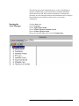
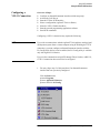
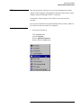
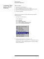
Starting the
Asset Manager
Click the Start menu,
point to Programs,
point to Agilent Signal Studio,
point to E7501A Signal Development System,
point to E7501A Signal Developer,
point to the pull down View menu and click Configuration.
Agilent E7501A Getting Started 1-11
Installation and Configuration
Step 4. Configuring Hardware/Software Assets
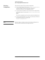
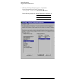
Selecting a
Configuration
Select either the Agilent E7501A or Demo configuration.
If you select the Agilent E7501A as the Current Configuration ,
you must configure a Stimulus Server with a minimum of
one RF Source and zero or more Modulation Sources.
If you do not have any hardware assets connected to the computer that is
running this software, you can set the Current Configuration to
Demo.
This selects a simulation asset for each role used by the Stimulus Server.
NOTE
If you have purchased other servers with your system, they will show on
the available list and can be selected as the
Current Configuration .
Each time changes are made to an asset in the selected configuration, the
software must be restarted before the changes take effect.
1-12 Agilent E7501A Getting Started
Installation and Configuration
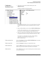
Step 4. Configuring Hardware/Software Assets
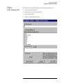
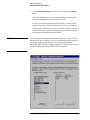
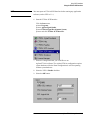
Configuring an
RF Source
1. From the list of assets in the left-hand window pane, select RF Source.
A dialog box similar to the following appears.
The left-hand window pane is a tree view of assets that can be selected.
The right-hand window pane shows information related to a selected
asset.
2. Select an RF Source such as the Agilent/HP E6432 RF Source.
3. Select any of the fields in the right-hand window pane and an entry box
or drop-down selection box will open and allow the field to be edited.
For example, you could edit the asset name, comment, address,
interface bus, or the VISA library being used by the RF Source.
To Edit the Asset Name Field
Select the Asset Name field and type Agilent/HP E6432 RF Source or any
name that you would like for this asset.
To Edit the Comment Field
Select the Comment field and type a comment for this asset.
To Edit the Address Field
Select the Address field and type an address such as 210. The address being
used must match the actual address of the hardware.
To Edit the Bus Field
Select the Bus field and select a bus from the drop-down selection box that is
to be used with this asset.
Agilent E7501A Getting Started 1-13
Installation and Configuration
Step 4. Configuring Hardware/Software Assets
To Edit the VISA Library Field
Select the VISA Library field and select either Agilent Technologies or
National Instruments from the drop-down selection box.
The selection that you make is dependent on the Slot 0 module being used
with your system.
Slot 0 Module Being Used
VISA Library
Agilent Technologies E8491B
IEEE-1394 PC Link to VXI
Agilent Technologies
Agilent Technologies 9850A
VXI Embedded PC Controller
or equivalent
Agilent Technologies
National Instruments VXI-MXI-2
National Instruments
This is important because a unique copy of the visa32.dll is used by both the
Agilent Technologies and National Instruments VISA Library, and both of
these libraries use a different version of this file. The most current
installation of one of these VISA Libraries will have their version of the
visa32.dll file installed. So, the VISA Library that is selected must
correspond with the Slot 0 module being used.
1-14 Agilent E7501A Getting Started
Installation and Configuration
Step 4. Configuring Hardware/Software Assets
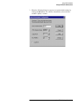
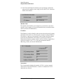
Configuring a
Modulation Source
1. From the list of assets in the left-hand window pane, select
Modulation Source.
A dialog box similar to the following appears.
The left-hand window pane is a tree view of assets that can be selected.
The right-hand window pane shows information related to a selected
asset.
2. Select an AM modulation source such as the RI3153 AM Mod Source.
An FM or Pulse modulation source can be configured using the same
process that is used when configuring an AM modulation source.
3. Select any of the fields in the right-hand window pane and an entry box
or drop-down selection box will open and allow the field to be edited.
For example, you could edit the asset name, comment, address,
interface bus, or the VISA library being used by the
RI3153 AM Mod Source.
To Edit the Asset Name Field
Select the Asset Name field and type RI3153 AM Mod Source or any name
that you would like for this asset.
To Edit the Comment Field
Select the Comment field and type a comment for this asset.
To Edit the Address Field
Select the Address field and type an address such as 3 for this asset. The
address being used must match the actual address of the hardware.
To Edit the Bus Field
Select the Bus field and select a bus from the drop-down selection box that is
to be used with this asset.
Agilent E7501A Getting Started 1-15
Installation and Configuration
Step 4. Configuring Hardware/Software Assets
To Edit the Channel Field
Select the Channel field and select the channel from the drop-down
selection box that is to be used with this asset.
CAUTION
The following table shows the default channel that is used with each output
of a Racal 3153 waveform generator. When changes are made to the channel
field, the corresponding cabling on the front panels must also be changed.
Agilent Technologies E6432A
Racal 3153
Default Channel
Pulse
Output 1
1
FM
Output 2
2
AM
Output 3
3
The default channel settings should not be changed unless you understand
that changing these channels also changes the filters and frequency ranges
used by each of these channels.
To Edit the Filter Field
Select the Filter[1,2,3] field and enter the directory path and file name to
designate a particular correction file. This correction file is used to correct
(offset) the response of a built-in filter. (For example, when using the
Racal 3153 waveform generator as the modulation source, a correction file
named C:\Temp\Filter_AM_1.txt could be created that contains values
to offset the response of the built-in filter for Channel 3.)
Each correction file must contain correction-value pairs in a sequential list.
The list is composed of a frequency point and an offset power value that is to
be applied at each specific frequency point. Unspecified points, between
correction points, are interpolated.
(Optional)
Configuring Other
Available Assets
The process for configuring other available assets follows a similar process
to configuring an RF source and a modulation source.
1-16 Agilent E7501A Getting Started
Installation and Configuration
Step 4. Configuring Hardware/Software Assets
(Optional) Adding a
Hardware/Software
Asset
1. Click the Add Asset icon (
).
2. Click the down arrow to expose all asset roles (different categories of
hardware/software assets) that are available in the currently selected
configuration.
As an example, we could add an RF Source as follows:
1. Click the Add Asset icon.
2. Click the down arrow to expose all asset roles that are available in the
currently selected configuration, and select RF Source.
3. Click the down arrow to expose all modules that fill the selected role and
select HP E6432 RF Source.
Agilent E7501A Getting Started 1-17
Installation and Configuration
Step 4. Configuring Hardware/Software Assets
4. Edit the name that you would like assigned to the newly added asset by
typing in the Asset Name field.
When finished editing the name, click OK.
5. The left-hand window pane should now show the newly added asset as
an RF Source that can be selected and used by the current configuration.
The right-hand window pane shows information related to the selected
RF Source. (For information related to changing the fields in the
right-hand window pane, refer to the section titled, “Configuring an
RF Source” on page 1-13.)
1-18 Agilent E7501A Getting Started
Installation and Configuration
Step 4. Configuring Hardware/Software Assets
(Optional) Removing a
Hardware/Software
Asset
When the Configuration view is selected, the left-hand window pane is a tree
view of available assets. The right-hand window pane shows information
related to a selected asset.
1. Select the general category (asset role) that an asset is to be removed
from by clicking the plus sign.
2. Select an asset to remove from the list that is exposed.
3. Click the Delete Asset icon (
NOTE
).
There is no Undo for this action. To get a deleted asset back into a
configuration, refer to the section titled, “(Optional) Adding a
Hardware/Software Asset” on page 1-17.
If you delete a configuration (such as Agilent E7501A or Demo), the fastest
way to restore them is to re-install the Agilent E7501A arbitrary analog
signal development system software. (For details on installation, refer to
“Step 3. Installing the Agilent E7501A Software” on page 1-7.)
Exiting Configuration
To exit Configuration, select a different view.
Agilent E7501A Getting Started 1-19
Installation and Configuration
Step 5. Starting the Agilent E7501A Software
Step 5. Starting the Agilent E7501A Software
1. Click the Start menu,
point to Programs,
point to Agilent Signal Studio,
point to E7501A Signal Development System,
point to and click E7501A Signal Developer.
2. The Agilent E7501A arbitrary analog signal developer software should
open and be ready for use.
At this point, an Acceptance Test Procedure (ATP) may be performed.
The ATP is a set of manual tests and is documented in the section of
“Performing Acceptance Test Procedures” on page 2-1. The ATP is
intended as a functionality check and is not intended for testing against
customer specifications.
1-20 Agilent E7501A Getting Started
2
Performing Acceptance Test Procedures
In this chapter, you will learn about:
•
Performing Acceptance Test Procedures
After satisfying the requirements and steps detailed in Chapter 1,
“Installation and Configuration””, the following manual Acceptance Test
Procedure (ATP) may be performed.
Performing an ATP is not required and is provided and intended as a
functionality check only; it is not intended for testing against customer
specifications. This ATP consists of a set of tests that can be performed in
under two hours with a minimum of test equipment.
Acceptance Tests
•
•
•
•
•
“Test 1. CW Frequency and Power” on page 2-2
•
“Test 6. Verify Synchronization of the Racal 3153” on page 2-16
“Test 2. AM Accuracy” on page 2-5
“Test 3. FM Accuracy” on page 2-8
“Test 4. Pulse Modulation Level Accuracy” on page 2-11
“Test 5. Verify Hopping with Two Pulse Modulated Signals” on
page 2-14
Required Test Equipment or Equivalent
•
•
Agilent E7501A arbitrary analog signal developer
Agilent 8563E spectrum analyzer
Agilent E7501A Getting Started 2-1
Performing Acceptance Test Procedures
Test 1. CW Frequency and Power
Test 1. CW Frequency and Power
Description
During this test, the system is set to two different frequencies at two different
power levels, and the output signal is measured with a spectrum analyzer.
Equipment Required
•
•
Agilent E7501A arbitrary analog signal developer
Agilent 8563E spectrum analyzer
Equipment Setup
NOTE
All test equipment requires a 30 minute warm-up period to ensure warranted
performance. Both the Agilent E7501A arbitrary analog signal developer
and the Agilent 8563E spectrum analyzer need to be connected to a common
10 MHz reference.
When using the Agilent E7501A arbitrary analog signal developer, ensure
that Reference is set to External; the Reference can be selected from the RF
Source Control view.
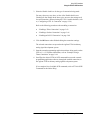
Step 1.
Use a high frequency 3.5 mm cable to connect the Agilent E7501A arbitrary
analog signal developer output to the input of the Agilent 8563E
spectrum analyzer.
2-2 Agilent E7501A Getting Started
Performing Acceptance Test Procedures
Test 1. CW Frequency and Power
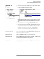
Step 2.
Agilent E7501A Summary
Agilent E7501A Details
Reset
1. From the pull down View menu,
select Reset View Settings and Windows.
Reference = External
2. From the RF Source Control view,
select Reference and set it to External.
Frequency = 1 GHz
3. From the RF Source Control view,
select Frequency Units and set it to GHz.
4. From the RF Source Control view,
highlight the Frequency field and enter 1 using the keyboard.
Power = +10 dBm
5. From the RF Source Control view,
highlight the Power field and enter 10 using the keyboard.
RF On = Enabled
6. From the RF Source Control view,
select the RF Output Enable check box.
Agilent 8563E Summary
Agilent 8563E Details
Preset
1. Press the green Preset front panel key.
Frequency = 1 GHz
2. Press the Frequency front panel key and enter 1 GHz.
Span = 1 MHz
3. Press the Span front panel key and enter 1 MHz.
Reference Level = +20 dBm
4. Press the Amplitude front panel key and enter +20 dBm; this sets
a reference level.
Marker, Peak Search
5. Press the Mkr and Peak Search front panel keys.
Record Marker value for
1 GHz and 10 dBm.
6. Enter the marker value in Table 2-1 for 1 GHz and 10 dBm.
Agilent E7501A Summary
Agilent E7501A Details
Auto Atten = Disabled
1. From the RF Source Control view,
unselect the Auto Atten check box so that the attenuator can be
manually controlled.
Attenuation = 50 dB
2. From the RF Source Control view,
highlight the Attenuation field and enter 50 using the keyboard.
Agilent 8563E Summary
Agilent 8563E Details
Marker, Peak Search
1. Press the Mkr and Peak Search front panel keys.
Record Marker value for
1 GHz and -40 dBm.
2. Enter the marker value in Table 2-1 for 1 GHz and -40 dBm.
Step 3.
Agilent E7501A Getting Started 2-3
Performing Acceptance Test Procedures
Test 1. CW Frequency and Power
Step 4.
Agilent E7501A Summary
Agilent E7501A Details
Frequency = 10 GHz
1. From the RF Source Control view,
highlight the Frequency field and enter 10 using the keyboard.
Agilent 8563E Summary
Agilent 8563E Details
Frequency = 10 GHz
1. Press the Frequency front panel key and enter 10 GHz.
Marker, Peak Search
2. Press the Mkr and Peak Search front panel keys.
Record Marker value for 10 GHz 3. Enter the marker value in Table 2-1 for 10 GHz and -40 dBm.
and -40 dBm.
Step 5.
Agilent E7501A Summary
Agilent E7501A Details
Attenuation = 0 dB
1. From the RF Source Control view,
highlight the Attenuation field and enter 0 using the keyboard.
Agilent 8563E Summary
Agilent 8563E Details
Marker, Peak Search
1. Press the Mkr and Peak Search front panel keys.
Record Marker value for 10 GHz 2. Enter the marker value in Table 2-1 for 10 GHz and 10 dBm.
and 10 dBm.
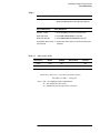
Table 2-1
Maximum Power Table
Test Frequency
Selected Power
Measured Power
Test Limits
1 GHz
10 dBm
dBm
10 GHz
-40 dBm
dBm
1 GHz
10 dBm
dBm
10 GHz
-40 dBm
dBm
2-4 Agilent E7501A Getting Started
Performing Acceptance Test Procedures
Test 2. AM Accuracy
Test 2. AM Accuracy
Description
This test is used to verify that AM modulation is working correctly.
The Agilent E6432A microwave synthesizer is configured for linear AM and
a spectrum analyzer is used to measure sidebands. The AM output of the
Racal 3153 arbitrary waveform generator drives the Agilent E6432A
microwave synthesizer AM input. The test is performed at carrier
frequencies of 10 MHz and 20 GHz, with AM depth of 100%, and an
AM rate of 10 kHz.
Equipment Required
•
•
Agilent E7501A arbitrary analog signal developer
Agilent 8563E spectrum analyzer
Equipment Setup
NOTE
All test equipment requires a 30 minute warm-up period to ensure warranted
performance. Both the Agilent E7501A arbitrary analog signal developer
and the Agilent 8563E spectrum analyzer need to be connected to a common
10 MHz reference.
When using the Agilent E7501A arbitrary analog signal developer, ensure
that Reference is set to External; the Reference can be selected from the RF
Source Control view.
Step 1.
Use a high frequency 3.5 mm cable to connect the Agilent E7501A arbitrary
analog signal developer output to the input of the Agilent 8563E
spectrum analyzer.
Agilent E7501A Getting Started 2-5
Performing Acceptance Test Procedures
Test 2. AM Accuracy
Step 2.
Agilent E7501A Summary
Agilent E7501A Details
Reset
1. From the pull down View menu,
select Reset View Settings and Windows.
Reference = External
2. From the RF Source Control view,
select Reference and set it to External.
Frequency = 10 MHz
3. From the RF Source Control view,
select Frequency Units and set it to MHz.
4. From the RF Source Control view,
highlight the Frequency field and enter 10 using the keyboard.
Power = 0 dBm
5. From the RF Source Control view,
highlight the Power field and enter 0 using the keyboard.
AM = Enabled
6. From the Stimulus Parameters view,
select the AM tab.
7. On the AM tab,
select the Value field for AM Rate and enter 10000 (10 kHz).
8. From the RF Source Control view,
select the AM check box.
RF On = Enabled
9. From the RF Source Control view,
select the RF Output Enable check box.
Agilent 8563E Summary
Agilent 8563E Details
Preset
1. Press the green Preset front panel key.
Frequency = 10 MHz
2. Press the Frequency front panel key and enter 10 MHz.
Span = 100 kHz
3. Press the Span front panel key and enter 100 kHz.
Reference Level = +10 dBm
4. Press the Amplitude front panel key and enter +10 dBm; this sets
a reference level.
Marker, Peak Search
5. Press the Mkr and Peak Search front panel keys.
Marker Delta, Next Peak
6. Press the Marker Delta and Next Peak front panel keys.
Record Marker value for
10 MHz and 10 kHz Rate.
7. Enter the marker value in Table 2-2 for 10 MHz test frequency and
10 kHz Rate
2-6 Agilent E7501A Getting Started
Performing Acceptance Test Procedures
Test 2. AM Accuracy
Step 3.
Agilent E7501A Summary
Agilent E7501A Details
Frequency = 20 GHz
1. From the RF Source Control view,
highlight the Frequency field and enter 20 using the keyboard.
Agilent 8563E Summary
Agilent 8563E Details
Frequency = 20 GHz
1. Press the Frequency front panel key and enter 20 GHz.
Marker, Peak Search
2. Press the Mkr and Peak Search front panel keys.
Marker Delta, Next Peak
3. Press the Marker Delta and Next Peak front panel keys.
Record Marker value for 20 GHz 4. Enter the marker value in Table 2-2 for 20 GHz test frequency and
10 kHz Rate.
and 10 kHz Rate.
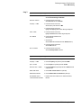
Table 2-2
AM Accuracy Table
Test Frequency
AM Rate
AM Depth
Measured Power
Test Limits
10 MHz
10 kHz
100%
dBm
20 GHz
10 kHz
100%
dBm
AM Accuracy Test Limit = ±12% and is calculated as follows:
Esb (dB) – Ec (dB) = 20 log m/2
where: Esb = the amplitude of the AM sideband
Ec = the amplitude of the carrier
m = modulation percent expressed as a fraction
Agilent E7501A Getting Started 2-7
Performing Acceptance Test Procedures
Test 3. FM Accuracy
Test 3. FM Accuracy
Description
This test is used to verify that FM modulation is working correctly.
The Agilent E6432A microwave synthesizer and the Racal 3153 arbitrary
waveform generator are configured for a modulation index of 2.404 which is
approximately a null of the Bessel function Jo. The amplitude of the function
generator is varied until the carrier being monitored on the spectrum
analyzer is a minimum. The function generator amplitude is then recorded
and compared to the theoretical value to calculate the FM accuracy error.
The test is performed at carrier frequencies of 10 MHz and 20 GHz, with an
FM Rate of 200 kHz.
Equipment Required
•
•
Agilent E7501A arbitrary analog signal developer
Agilent 8563E spectrum analyzer
Equipment Setup
NOTE
All test equipment requires a 30 minute warm-up period to ensure warranted
performance. Both the Agilent E7501A arbitrary analog signal developer
and the Agilent 8563E spectrum analyzer need to be connected to a common
10 MHz reference.
When using the Agilent E7501A arbitrary analog signal developer, ensure
that Reference is set to External; the Reference can be selected from the RF
Source Control view.
Step 1.
Use a high frequency 3.5 mm cable to connect the Agilent E7501A arbitrary
analog signal developer output to the input of the Agilent 8563E
spectrum analyzer.
2-8 Agilent E7501A Getting Started
Performing Acceptance Test Procedures
Test 3. FM Accuracy
Step 2.
Agilent E7501A Summary
Agilent E7501A Details
Reset
1. From the pull down View menu,
select Reset View Settings and Windows.
Reference = External
2. From the RF Source Control view,
select Reference and set it to External.
Frequency = 10 MHz
3. From the RF Source Control view,
select Frequency Units and set it to MHz.
4. From the RF Source Control view,
highlight the Frequency field and enter 10 using the keyboard.
Power = 0 dBm
5. From the RF Source Control view,
highlight the Power field and enter 0 using the keyboard.
FM = Enabled
6. From the Stimulus Parameters view,
select the FM tab.
7. On the FM tab,
select the Value field for FM Rate and enter 200000 (200 kHz).
8. From the RF Source Control view,
select the FM check box.
RF On = Enabled
9. From the RF Source Control view,
select the RF Output Enable check box.
Agilent 8563E Summary
Agilent 8563E Details
Preset
1. Press the green Preset front panel key.
Frequency = 10 MHz
2. Press the Frequency front panel key and enter 10 MHz.
Span = 100 kHz
3. Press the Span front panel key and enter 100 kHz.
Reference Level = +10 dBm
4. Press the Amplitude front panel key and enter +10 dBm; this sets
a reference level.
Marker, Peak Search
5. Press the Mkr and Peak Search front panel keys.
Marker Delta, Next Peak
6. Press the Marker Delta and Next Peak front panel keys.
Record Marker value for
10 MHz and 200 kHz FM Rate.
7. Enter the marker value in Table 2-3 for 10 MHz and 200 kHz
FM Rate.
Agilent E7501A Getting Started 2-9
Performing Acceptance Test Procedures
Test 3. FM Accuracy
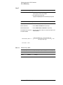
Step 3.
Agilent E7501A Summary
Agilent E7501A Details
Frequency = 20 GHz
1. From the RF Source Control view,
select Frequency Units and set it to GHz.
2. From the RF Source Control view,
highlight the Frequency field and enter 20 using the keyboard.
Agilent 8563E Summary
Agilent 8563E Details
Frequency = 20 GHz
1. Press the Frequency front panel key and enter 20 GHz.
Marker, Peak Search
2. Press the Mkr and Peak Search front panel keys.
Marker Delta, Next Peak
3. Press the Marker Delta and Next Peak front panel keys.
Record Marker value for 20 GHz 4. Enter the marker value in Table 2-2 for 20 GHz test frequency and
200 kHz FM Rate.
and 200 kHz FM Rate.
Calc Fgen Amp Vpp – Act Fgen Amp Vpp
FM Accuracy Error % = ------------------------------------------------------------------------------------------------------- × 100
Calc Fgen Amp Vpp
Test Limit = +40%
Table 2-3
FM Accuracy Table
Test Frequency
FM Rate
Calc Fgen Amp Vpp Act Fgen Amp Vpp
10 MHz
200 kHz
1.92 Vpp
20 GHz
200 kHz
1.92 Vpp
2-10 Agilent E7501A Getting Started
FM Accuracy Error%
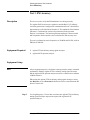
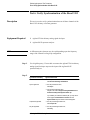
Test 4. Pulse Modulation Level Accuracy
Description
The Agilent E6432A microwave synthesizer and the Agilent E7501A
arbitrary analog signal developer is configured for pulse modulation. A
spectrum analyzer is used in zero span to measure the amplitude of the pulse
envelope. This measured value is compared to the CW amplitude with pulse
modulation turned off. Depending on the model of spectrum analyzer used,
the Pulse Repetition Frequency (PRF) may need to be decreased to measure
the pulse.
Equipment Required
•
•
Agilent E7501A arbitrary analog signal developer
Agilent 8563E spectrum analyzer
Equipment Setup
NOTE
All test equipment requires a 30 minute warm-up period to ensure warranted
performance. Both the Agilent E7501A arbitrary analog signal developer
and the Agilent 8563E spectrum analyzer need to be connected to a common
10 MHz reference.
When using the Agilent E7501A arbitrary analog signal developer, ensure
that Reference is set to External; the Reference can be selected from the RF
Source Control view.
Step 1.
Use a high frequency 3.5 mm cable to connect the Agilent E7501A arbitrary
analog signal developer output to the input of the Agilent 8563E
spectrum analyzer.
Agilent E7501A Getting Started 2-11
Performing Acceptance Test Procedures
Test 4. Pulse Modulation Level Accuracy
Step 2.
Agilent E7501A Summary
Agilent E7501A Details
Reset
1. From the pull down View menu,
select Reset View Settings and Windows.
Reference = External
2. From the RF Source Control view,
select Reference and set it to External.
Frequency = 1 GHz
3. From the RF Source Control view,
select Frequency Units and set it to GHz.
4. From the RF Source Control view,
highlight the Frequency field and enter 1 using the keyboard.
Power = 0 dBm
5. From the RF Source Control view,
highlight the Power field and enter 0 using the keyboard.
Pulse = Enabled
6. From the RF Source Control view,
select the Pulse check box.
RF On = Enabled
7. From the RF Source Control view,
select the RF Output Enable check box.
Agilent 8563E Summary
Agilent 8563E Details
Preset
1. Press the green Preset front panel key.
Frequency = 1 GHz
2. Press the Frequency front panel key and enter 1 GHz.
Span = 100 kHz
3. Press the Span front panel key and enter 100 kHz.
Reference Level = +10 dBm
4. Press the Amplitude front panel key and enter +10 dBm; this sets
a reference level.
Marker, Peak Search
5. Press the Mkr and Peak Search front panel keys.
Marker Delta, Next Peak
6. Press the Marker Delta and Next Peak front panel keys.
Record Marker value for
1 GHz and 30 kHz PRF.
7. Enter the marker value in Table 2-4 for 1 GHz and 30 kHz PRF.
2-12 Agilent E7501A Getting Started
Performing Acceptance Test Procedures
Test 4. Pulse Modulation Level Accuracy
Step 3.
Agilent E7501A Summary
Agilent E7501A Details
Frequency = 20 GHz
1. From the RF Source Control view,
select Frequency Units and set it to GHz.
2. From the RF Source Control view,
highlight the Frequency field and enter 20 using the keyboard.
Agilent 8563E Summary
Agilent 8563E Details
Frequency = 20 GHz
1. Press the Frequency front panel key and enter 20 GHz.
Marker, Peak Search
2. Press the Mkr and Peak Search front panel keys.
Marker Delta, Next Peak
3. Press the Marker Delta and Next Peak front panel keys.
Record Marker value for 20 GHz 4. Enter the marker value in Table 2-4 for 20 GHz test frequency and
30 kHz PRF.
and 30 kHz PRF.
Accuracy = – ( Carrier Amplitude – Pulse Amplitude)
Table 2-4
Pulse Leveled Accuracy Table
Test
Frequency
PRF
Pulse Amplitude
Carrier
Amplitude
Accuracy
Test Limit
1 GHz
30 kHz
±2 dB
20 GHz
30 kHz
±2 dB
Agilent E7501A Getting Started 2-13
Performing Acceptance Test Procedures
Test 5. Verify Hopping with Two Pulse Modulated Signals
Test 5. Verify Hopping
with Two Pulse Modulated Signals
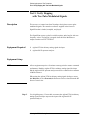
Description
This test uses a “canned waveform” that hops slowly between two pulse
modulated signals. The canned waveform is supplied in the form of a
Signal Plan that is loaded, compiled, and played.
The Signal Plan creates a pulse list with four pulses and a hop list with two
frequency values. The hop list is stepped when the Pulse Mod Source
outputs a marker on VXI TTLTRG4.
Equipment Required
•
•
Agilent E7501A arbitrary analog signal developer
Agilent 8563E spectrum analyzer
Equipment Setup
NOTE
All test equipment requires a 30 minute warm-up period to ensure warranted
performance. Both the Agilent E7501A arbitrary analog signal developer
and the Agilent 8563E spectrum analyzer need to be connected to a common
10 MHz reference.
When using the Agilent E7501A arbitrary analog signal developer, ensure
that Reference is set to External; the Reference can be selected from the RF
Source Control view.
Step 1.
Use a high frequency 3.5 mm cable to connect the Agilent E7501A arbitrary
analog signal developer output to the input of the Agilent 8563E
spectrum analyzer.
2-14 Agilent E7501A Getting Started
Performing Acceptance Test Procedures
Test 5. Verify Hopping with Two Pulse Modulated Signals
Step 2.
Agilent E7501A Summary
Agilent E7501A Details
Reset
1. From the pull down View menu,
select Reset View Settings and Windows.
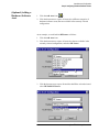
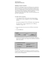
Open a Signal Plan
2. From the pull down File menu,
select Open.
3. In the browser window that opens,
navigate to the folder C:\Program Files\Agilent\Measurement
and Stimulus Subsystems\FreqHopAndPulse.ssp.
If you installed your software in a different path, you may need to
use the program: Start/Find/Files or Folders and enter
FreqHopAndPulse.ssp in the browser window that appears.
Compile the Signal Plan
4. From the pull down Signal Plan menu,
select Compile All.
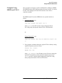
Play the Signal Plan
5. From the pull down Signal Plan menu,
select Play.
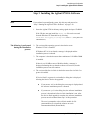
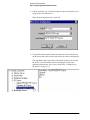
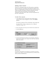
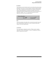
To view the signal that is created, set up a
spectrum analyzer at a center frequency of
1 GHz with a 50 MHz span. Shown below are
the two signals that should be visible. Note that
the two signals may be reversed; this is
dependent on when the Racal 3153 waveform
generator triggers the hop list.
Agilent E7501A Getting Started 2-15
Performing Acceptance Test Procedures
Test 6. Verify Synchronization of the Racal 3153
Test 6. Verify Synchronization of the Racal 3153
Description
This test is used to verify synchronization between all three channels of the
Racal 3153 arbitrary waveform generator.
Equipment Required
•
•
NOTE
Agilent E7501A arbitrary analog signal developer
Agilent 8563E spectrum analyzer
A different negative detector may be used depending upon the frequency
range of the external leveling loop configuration.
Step 1.
Step 2.
Use a high frequency 3.5 mm cable to connect the Agilent E7501A arbitrary
analog signal developer output to the input of the Agilent 8563E
spectrum analyzer.
Agilent E7501A Summary
Agilent E7501A Details
Reset
1. From the pull down View menu,
select Reset View Settings and Windows.
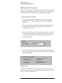
Open a Signal Plan
2. From the pull down File menu,
select Open.
3. In the browser window that opens,
navigate to the folder C:\Program Files\Agilent\Measurement
and Stimulus Subsystems\Synchronization.ssp.
If you installed your software in a different path, you may need to
use the program: Start/Find/Files or Folders and enter
Synchronization.ssp in the browser window that appears.
Compile the Signal Plan
4. From the pull down Signal Plan menu,
select Compile All.
Play the Signal Plan
5. From the pull down Signal Plan menu,
select Play.
2-16 Agilent E7501A Getting Started
3
Using SCPI Interfaces
In this chapter, you will learn about:
•
•
“Using the E7501A SCPI Assistant” on page 3-19
“Using the E7501A SCPI Interface” on page 3-27
“Understanding the E7501A SCPI Interface” on page 3-27
“Making a Connection” on page 3-28
“Configuring a VXI-11 Connection” on page 3-29
“Configuring a Telnet, Sockets, or RS-232 Connection” on
page 3-40
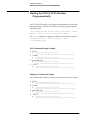
How to proceed…
First, after you have decided to use SCPI commands to control your
hardware, select either the E7501A SCPI assistant, the
E7501A SCPI interface, or both.
If you select to use a E7501A SCPI interface, you must select a
connection type and follow the directions for setting it up. When ready,
become familiar with the SCPI interface panels and each of its various
sections. To learn more about all available SCPI commands, refer to the
Online Help system that is available from the main GUI of the Agilent
E7501A arbitrary analog signal developer software.
Agilent E7501A Getting Started 3-17
Using SCPI Interfaces
Overview of SCPI Interfaces
Overview of SCPI Interfaces
In addition to the Agilent E7501A arbitrary analog signal developer user
interface, your hardware can be controlled through either or both of the
following SCPI interfaces.
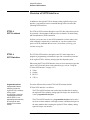
E7501A
SCPI Assistant
The E7501A SCPI assistant, through its own GUI, takes input from a person.
It’s primarily a development aid that provides an interface for both testing
and demonstration of SCPI commands.
It allows you to enter one or more SCPI commands at a time (where each
valid command is separated by a semicolon) or view the response from
queries of SCPI commands that are sent; it even allows you to log your
sessions in a log file.
E7501A
SCPI Interface
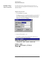
The E7501A SCPI interface, through its own GUI, takes input from a
program or programming environment. It provides a connectivity interface
to the Agilent E7501A arbitrary analog signal development system.
When using the E7501A SCPI interface, there are four connection types that
can be used. (For details about each connection type, refer to “Using the
E7501A SCPI Interface” on page 3-27.)
•
•
•
•
Programmable Interface
A programmable interface
allows you to control the
Agilent E7501A arbitrary
analog signal
development system from
a programming environment
such as VEE or C++; the
programming environment may
be running on the same
machine or from a remote
machine.
Telnet
Sockets
RS-232
VXI-11
The main difference between the E7501A SCPI assistant and the
E7501A SCPI interface is as follows:
The E7501A SCPI assistant runs on the same machine that is running
the Agilent E7501A arbitrary analog signal developer user interface, but
is not a programmable interface.
The E7501A SCPI interface is a programmable interface and it can be
run from a remote machine or through a remote communication port on
the same machine that is running the Agilent E7501A arbitrary analog
signal developer user interface.
3-18 Agilent E7501A Getting Started
Using SCPI Interfaces
Using the E7501A SCPI Assistant
Using the E7501A SCPI Assistant
Agilent E7501A Getting Started 3-19
Using SCPI Interfaces
Using the E7501A SCPI Assistant
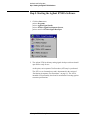
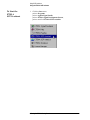
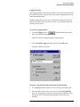
To Start the
E7501A
SCPI Assistant
1. Click the Start menu,
point to Programs,
point to Agilent Signal Studio,
point to E7501A Signal Development System,
point to and click E7501A SCPI Assistant.
3-20 Agilent E7501A Getting Started
Using SCPI Interfaces
Using the E7501A SCPI Assistant
E7501A
SCPI Assistant GUI
The E7501A SCPI assistant consists of the following main sections:
•
•
•
•
SCPI Command Entry Box
Quick Reference Guide Selection Box
Query Response Box
Indicators and Related Functions
Agilent E7501A Getting Started 3-21
Using SCPI Interfaces
Using the E7501A SCPI Assistant
SCPI Assistant
SCPI Command
Entry Box
The SCPI Command Entry Box allows you to enter one or more SCPI
commands with their parameters, and send them to the Agilent E7501A
arbitrary analog signal development system. Multiple SCPI commands can
be sent by separating commands with semicolons.
To send SCPI commands from the SCPI Command Entry Box
Type any of the SCPI commands with their parameters in the
SCPI Command Entry Box and click the Send button (
); you can
also use the Enter key on your computer’s keyboard. Multiple SCPI
commands can be sent by separating commands with semicolons.
SCPI Assistant
Quick Reference
Guide Selection Box
The Quick Reference Guide Selection Box consists of a list of all available
SCPI commands for the Agilent E7501A arbitrary analog signal developer.
To send a SCPI command from the Quick Reference Guide
Selection Box
1. Double-click on a command in the Quick Reference Guide
Selection Box and it is placed in the SCPI Command Entry Box.
If the command does not have any required parameters, it is
executed immediately.
If the command requires parameters, a value must be entered for
each required parameter before the command is executed.
To view a complete list of available SCPI commands
1. Click the View QRG button (
the E7501A SCPI assistant.
) available from the bottom of
To print a complete list of available SCPI commands
1. Click the View QRG button (
the E7501A SCPI assistant.
) available from the bottom of
2. Use standard Windows’ printing capabilities once the list is displayed.
As an example, if the SCPI commands are displayed by
Microsoft Notepad, select Print from the pull down File menu.
3-22 Agilent E7501A Getting Started
Using SCPI Interfaces
Using the E7501A SCPI Assistant
SCPI Assistant
Query Response Box
The Query Response Box displays all returned responses that are generated
from SCPI commands being sent.
To clear the Query Response Box
1. Click the Clear button (
Query Response Box.
) available above the
This clears the Query Response buffer and the Query Response Box.
Agilent E7501A Getting Started 3-23
Using SCPI Interfaces
Using the E7501A SCPI Assistant
SCPI Assistant
Indicators and
Related Functions
The following Indicators and Related Functions are available:
•
•
•
•
•
•
SYSTem:ERRor? Function
SRQ Event Indicator
Status, Error, Warning Messages
Device Clear Function
Logging Function
View QRG [Quick Reference Guide] Function
SYSTem:ERRor? Function
The SYSTem:ERRor? button is a shortcut button that allows the
SYSTem:ERRor? command to be executed without having to type it in the
SCPI Command Entry Box or locate it in the Quick Reference Guide
Selection Box.
SRQ Event Indicator
The SRQ [Service Request] Event light indicates that an SRQ interrupt has
taken place. This event can be cleared with the *CLS button. Before the SRQ
Event indicator will operate, SRQs must be enabled using SCPI status
commands. (Refer to Online Help for information on using each of the SCPI
status commands.)
The *CLS button is a shortcut button that allows the clear command to be
executed without having to type it in the SCPI Command Entry Box or
locate it in the Quick Reference Guide Selection Box.
Status, Error, Warning Messages
This section displays server status, error, and warning messages that occur
due to the SCPI commands that are sent using either the SCPI Command
Entry Box or the Quick Reference Guide Selection Box.
Device Clear Function
Device Clear is used to clear any commands from the SCPI Command
Entry Box.
3-24 Agilent E7501A Getting Started
Using SCPI Interfaces
Using the E7501A SCPI Assistant
Logging Function
The Logging function is available in both the E7501A SCPI assistant and the
E7501A SCPI interface; the procedure for using the Logging function is the
same from both interfaces.
Enabling logging allows you to log Commands Sent, Query Responses, or
both. All log entries can be saved in a text file (*.log) using the name and
directory of your choice.
To start the Logging function
1. Click the Logging button (
the E7501A SCPI assistant.
) available from the bottom of
The SCPI Assistant Logging dialog box should appear.
2. Click the Enable Logging checkbox and select the OK button.
Logging is disabled by default.
To specify a log file that is different from the default filename
1. Use the Browse button to open a browser and select a directory path.
2. Enter the name of the log file you wish to use in the Log File Name
entry box. By default, the log file is stored in the same directory where
the Agilent E7501A arbitrary analog signal developer software is
installed.
Agilent E7501A Getting Started 3-25
Using SCPI Interfaces
Using the E7501A SCPI Assistant
To display the contents of the log file
1. Select the View Log button and the log file is displayed in
Microsoft Notepad.
To clear the contents of the log file
1. Select the Clear Log button and all entries in the log file are cleared.
3-26 Agilent E7501A Getting Started
Using SCPI Interfaces
Using the E7501A SCPI Interface
Using the E7501A SCPI Interface
Understanding the
E7501A
SCPI Interface
The E7501A SCPI interface, through its own GUI, takes input from a
program or programming environment. It provides a connectivity interface
to the Agilent E7501A arbitrary analog signal development system.
The E7501A SCPI interface GUI can be used with four connection types:
•
•
•
•
Telnet
Sockets
RS-232
VXI-11
Telnet, Sockets, and RS-232 come with all Microsoft Windows’ operating
systems. VXI-11 requires an Internal Instrument interface to be configured
with the I/O Config utility before it can be enabled; the I/O Config utility is
available only with Agilent I/O Libraries.
If you are using a National Instrument MXI-VXI Slot 0 module, a VXI-11
connection can not be enabled; it requires an Internal Instrument interface to
be configured, and this functionality is not available with
National Instruments MXI-VXI Slot 0 modules.
Telnet, Sockets, and VXI-11 each use different communication protocol
(communication rules), listen on different ports, and communicate over a
LAN [Local Area Network]; one or more sessions of communication can be
configured and used simultaneously.
RS-232 is a serial COM port interface that uses a direct cable (a null-modem
cable) between the computer running the Agilent E7501A arbitrary analog
signal development system and the computer running the user’s
programming environment.
Agilent E7501A Getting Started 3-27
Using SCPI Interfaces
Using the E7501A SCPI Interface
Making a Connection
Before sending any SCPI commands from an external programming
environment, decide which connection type you plan to use and follow the
steps to make one or more connections using:
Telnet, Sockets, RS-232, or VXI-11.
The following drawing shows the relationship between the host PC elements
and those elements that are part of the remote computer.
Depending on which connection type you plan to use, refer to one of the
following processes:
•
•
“Configuring a VXI-11 Connection” on page 3-29
“Configuring a Telnet, Sockets, or RS-232 Connection” on page 3-40
3-28 Agilent E7501A Getting Started
Using SCPI Interfaces
Using the E7501A SCPI Interface
Configuring a
VXI-11 Connection
Overview of Steps:
•
•
•
•
•
•
•
Configure an Internal Instrument interface (initial setup only).
Activate the LAN Server.
Start the E7501A SCPI Interface.
Select a configuration (Agilent E7501A or Demo).
Select the VXI-11 Enable checkbox.
Start the external programming application software.
Send SCPI commands.
Configuring a VXI-11 connection may require the following:
NOTE
If you wish to communicate with the Agilent E7501A arbitrary analog signal
development system from a remote computer using SCPI through a VXI-11
connection, you must configure an Internal Instrument interface with the
I/O Config utility before it can be enabled; the I/O Config utility is available
only with Agilent I/O Libraries.
If you wish to communicate using SCPI through Telnet, Sockets, or RS-232,
a VXI-11 connection does not need to be configured.
1. You may skip to step 5 of this procedure if an Internal Instrument
interface has been previously configured.
Click the Start menu,
point to Programs,
point to Agilent IO Libraries,
point to and click IO Config.
Agilent E7501A Getting Started 3-29
Using SCPI Interfaces
Using the E7501A SCPI Interface
2. Select Internal Instrument in the left pane and click the Configure
button.
If the Internal Instrument is not available as a choice in the left pane,
repeat the installation process using your setup CD.
In order for the Internal Instrument to be available, you must install
Agilent I/O Libraries. During the installation process, your computer is
checked for the installation of Agilent I/O Libraries and if it is found, an
Agilent I/O Library Upgrade is automatically performed; this upgrade is
what makes the Internal Instrument available.
NOTE
If you are using a National Instrument MXI-VXI Slot 0 module, a VXI-11
connection can not be enabled; it requires an Internal Instrument interface to
be configured, and this functionality is not available with National
Instruments MXI-VXI Slot 0 modules. Agilent I/O Libraries cannot be used
to control National Instruments MXI-VXI Slot 0 modules.
3-30 Agilent E7501A Getting Started
Using SCPI Interfaces
Using the E7501A SCPI Interface
3. When the following dialog box appears, accept the default settings by
clicking the OK button. The software automatically selects the next
available “hpib(x)” number.
Agilent E7501A Getting Started 3-31
Using SCPI Interfaces
Using the E7501A SCPI Interface
4. When the following dialog box appears, verify that the
Internal Instrument appears in the right-pane list
(Configured Interfaces) and click the OK button.
In the following example, the Internal Instrument is configured as:
3-32 Agilent E7501A Getting Started
SICL Name
VISA Name
hpib7
GPIB0
Using SCPI Interfaces
Using the E7501A SCPI Interface
NOTE
You must activate the LAN Server if you wish to communicate with the
Agilent E7501A arbitrary analog signal development system from a remote
computer using SCPI through a VXI-11 connection.
If not using a remote computer, the LAN Server does not need to be
activated.
If you wish to communicate using SCPI through Telnet, Sockets, or RS-232,
the LAN Server does not need to be configured.
5. Activate the LAN Server.
Click the Start menu,
point to Programs,
point to Agilent IO Libraries,
point to and click LAN Server.
Agilent E7501A Getting Started 3-33
Using SCPI Interfaces
Using the E7501A SCPI Interface
The LAN Server dialog box should appear and be ready to communicate
with a remote PC or Unix workstation. This dialog box does not display any
information, but it needs to be active for the LAN Server to function. The
window can be minimized. (To minimize the window, select the
minimize button in the upper-right corner of the dialog box.)
3-34 Agilent E7501A Getting Started
Using SCPI Interfaces
Using the E7501A SCPI Interface
NOTE
You must open an E7501A SCPI Interface before running any application
software (such as VEE or C++).
6. Start the E7501A SCPI Interface.
Click the Start menu,
point to Programs,
point to Agilent Signal Studio,
point to E7501A Signal Development System,
point to and click E7501A SCPI Interface.
7. Select the configuration that you would like to use:
Agilent E7501A or Demo. The Agilent E7501A configuration requires
system hardware while the Demo configuration is used for operating
without system hardware.
8. Select the VXI-11 Enable checkbox.
9. Select the OK button.
Agilent E7501A Getting Started 3-35
Using SCPI Interfaces
Using the E7501A SCPI Interface
10. The E7501A SCPI Interface Monitor opens and displays information
about the local machine you are using as well as the VXI-11 connection
that has been enabled.
Machine Name
The machine name identifies your computer on your network, such as the
network in your company. (For more information about your machine name,
contact your network administrator.)
IP Address
The IP address is used to identify a node on a network and to specify routing
information. Each node on a network must be assigned a unique IP address.
This address is made up of the network ID, plus a unique host ID assigned
by the network administrator. This address is typically represented in
dotted-decimal notation, with the decimal value of each octet separated by a
period (for example, 138.57.7.27). (For more information about IP
addressing, contact your network administrator.)
Connections
The Connections box displays the number of VXI-11 sessions currently
connected to E7501A SCPI interface. A total of 5 simultaneous VXI-11
connections are allowed.
3-36 Agilent E7501A Getting Started
Using SCPI Interfaces
Using the E7501A SCPI Interface
SICL Interface Name
The SICL Interface Name is a symbolic name that SICL uses to uniquely
identify an instrument interface. If your application software uses SICL I/O
libraries, use this name and the Logical Unit number to address the
instrument interface properly.
SICL Interface names are set using the I/O Config utility of
Agilent I/O Libraries.
VISA Interface Name
The VISA Interface Name is a symbolic name that VISA uses to uniquely
identify an instrument interface. If your application software uses VISA I/O
Libraries, use this name to address the instrument interface properly.
VISA Interface names are set using the I/O Config utility of
Agilent I/O Libraries.
SICL Logical Unit
SICL Logical Unit is a number that SICL uses to uniquely identify this
Instrument interface. If your application software uses SICL I/O Libraries,
use this number and the SICL Interface name in order to address this
Instrument interface properly.
SICL Logical Unit numbers are set using the I/O Config utility of
Agilent I/O Libraries.
Address of Subsystem
Address of Subsystem is the address of the Agilent subsystem on the
VXI-11 interface emulated GPIB bus. Application software should address
the subsystem using this device address.
The Address of Subsystem is set in the Interface Selection dialog.
NOTE
Note that the default address of the subsystem is 0 when the VXI-11
interface is used.
Agilent E7501A Getting Started 3-37
Using SCPI Interfaces
Using the E7501A SCPI Interface
Logging Function
The Logging function is available in both the E7501A SCPI assistant and the
E7501A SCPI interface; the procedure for using the Logging function is the
same from both interfaces.
Enabling logging allows you to log Commands Sent, Query Responses, or
both. All log entries can be saved in a text file (*.log) using the name and
directory of your choice.
(For further information on the Logging function, refer to page 3-25.)
11. Start the external programming application software being used (such as
VEE or C++). For further information, refer to “Examples Using HPBW
and VXI-11” on page 3-39.
12. Send/Type the desired E7501A SCPI commands between the external
programming application software, through the enabled connection, to
the Agilent E7501A arbitrary analog signal development system.
(For a complete list of available SCPI commands, refer to E7501A SCPI
Commands in the Online Help.)
3-38 Agilent E7501A Getting Started
Using SCPI Interfaces
Using the E7501A SCPI Interface
Examples Using
HPBW and VXI-11
These examples are language specific to HP BASIC for Windows (HPBW).
The HPBW program can be running on either the same local PC or a remote
PC that is also running the E7501A SCPI interface with a VXI-11
connection enabled.
The HPBW autost file uses the HPIBS driver to open the interface as
follows:
1. Using the Same PC, type:
LOAD BIN “HPIBS; DEV hpib7 ISC 7”
where, hpib7 is the SICL interface name configured with the
I/O Config utility and opened with the E7501A SCPI interface.
or
Using a Remote PC, type:
LOAD BIN “HPIBS; DEV lan[<IP address>]:hpib7 ISC
7”
2. Your program would then address the Agilent E7501A arbitrary analog
signal development system as follows:
OUTPUT 700; “*IDN?”
ENTER 700; Id$
where, <IP address> is the IP address of the PC that is running the
Agilent E7501A arbitrary analog signal development system, and
hpib7 is the SICL interface name configured with the I/O Config
utility and opened with the E7501A SCPI interface.
Agilent E7501A Getting Started 3-39
Using SCPI Interfaces
Using the E7501A SCPI Interface
Configuring a Telnet,
Sockets, or RS-232
Connection
Overview of Steps:
•
•
•
•
•
Start the E7501A SCPI Interface.
Select a configuration (Agilent E7501A or Demo).
Select the Enable check box for the type of connection being made.
Start the external programming application software.
Send SCPI commands.
Configuring a Telnet, Sockets, or RS-232 connection may require the
following procedures:
1. Start the E7501A SCPI Interface.
Click the Start menu,
point to Programs,
point to Agilent Signal Studio,
point to E7501A Signal Development System,
point to and click E7501A SCPI Interface.
2. Select the configuration that you would like to use:
Agilent E7501A or Demo. The Agilent E7501A configuration requires
system hardware while the Demo configuration is used for operating
without system hardware.
3-40 Agilent E7501A Getting Started
Using SCPI Interfaces
Using the E7501A SCPI Interface
3. Select the Enable check box for the type of connection being made.
You may select one, two, three, or four of the Enable check-boxes.
Checking all four Enable check-boxes gives access to the settings used
for each connection. (When selecting the VXI-11 enable checkbox, refer
to, “Configuring a VXI-11 Connection” on page 3-29.)
Refer to the following procedures when enabling a connection:
“Enabling a Telnet Connection” on page 3-42
“Enabling a Sockets Connection” on page 3-46
“Enabling an RS-232 Connection” on page 3-48
4. Click the OK button when finished editing the connection settings.
The selected connections are opened to the Agilent E7501A arbitrary
analog signal development system.
5. Start the external programming application software being used (such as
VEE or C++). For further information, refer to “Examples Using a
Telnet Connection” on page 3-44
6. Send/Type the desired E7501A SCPI commands between the external
programming application software, through the enabled connection, to
the Agilent E7501A arbitrary analog signal development system.
(For a complete list of available SCPI commands, refer to E7501A SCPI
Commands in the Online Help.)
Agilent E7501A Getting Started 3-41
Using SCPI Interfaces
Using the E7501A SCPI Interface
Enabling a Telnet Connection
Telnet uses a LAN interface along with TCP/IP protocol to communicate
between the Agilent E7501A arbitrary analog signal development system
and the user’s programming environment; each Telnet connection listens on
a unique port address and requires installed and configured networking
software. Telnet requires the IP address of the computer being
communicated with along with the address of the port being listened on by
the E7501A SCPI interface.
To enable a Telnet connection
1. After starting the E7501A SCPI interface and selecting either the
Agilent E7501A or Demo configuration, select the Telnet Enable
checkbox.
(For details on starting the E7501A SCPI Interface and selecting either
the Agilent E7501A or Demo configuration, refer to “Making a
Connection” on page 3-28.)
2. Enter a port number or leave the port set to 23; this is the default value.
3. Select the OK button.
4. The E7501A SCPI Interface Monitor opens and displays information
about the local machine you are using as well as the Telnet connection
that has been enabled.
Machine Name
The machine name identifies your computer on your network, such as the
network in your company. (For more information about your machine name,
contact your network administrator.)
3-42 Agilent E7501A Getting Started
Using SCPI Interfaces
Using the E7501A SCPI Interface
IP Address
The IP address is used to identify a node on a network and to specify routing
information. Each node on a network must be assigned a unique IP address.
This address is made up of the network ID, plus a unique host ID assigned
by the network administrator. This address is typically represented in
dotted-decimal notation, with the decimal value of each octet separated by a
period (for example, 138.57.7.27). (For more information about IP
addressing, contact your network administrator.)
Port
The Port box displays the number of the currently selected port being used
by the enabled Telnet connection. (For more information about ports, contact
your network administrator.)
Connections
The Connections box displays the number of Telnet sessions currently
connected to E7501A SCPI interface. A total of 5 simultaneous Telnet or
Sockets connections are allowed.
Agilent E7501A Getting Started 3-43
Using SCPI Interfaces
Using the E7501A SCPI Interface
Examples Using a
Telnet Connection
The Telnet program can be running on either the same local PC or a
remote PC that is also running the E7501A SCPI interface with a Telnet
connection enabled.
Using the Same Local PC
1. Select Start/Run and type telnet.
The telnet program must be installed and available on your local PC. If
it is available, a dialog box similar to the following might appear that
allows you to enter SCPI commands. The IP address of your local PC
could also be used in place of localhost.
2. Enter the SCPI command, *IDN?
If everything is working correctly with the Telnet connection, you
should see a response such as the following:
3-44 Agilent E7501A Getting Started
Using SCPI Interfaces
Using the E7501A SCPI Interface
Using a Remote PC such as Unix
1. From a Unix prompt, type: telnet <IP address>,
where, <IP address> is the IP address of the PC that is running the
opened E7501A SCPI interface. (In the previous section, “Enabling a
Telnet Connection” on page 3-42, the IP address was 141.121.82.18, but
the PC being connected to in your situation would be different.)
The telnet program must be installed and available on your Unix station.
If it is available, a dialog box similar to the following might appear that
allows you to enter SCPI commands.
2. Enter the SCPI command, *IDN?
If everything is working correctly with the Telnet connection, you
should see a response such as the following:
Agilent E7501A Getting Started 3-45
Using SCPI Interfaces
Using the E7501A SCPI Interface
Enabling a Sockets Connection
Sockets use a LAN interface along with TCP/IP protocol to communicate
between the Agilent E7501A arbitrary analog signal development system
and the user’s programming environment; each Sockets connection listens
on a unique port address and requires installed and configured networking
software. Sockets require the IP address of the computer being
communicated with along with the address of the port being listened on by
the E7501A SCPI interface.
To enable a Sockets connection
1. After starting the E7501A SCPI interface and selecting either the
Agilent E7501A or Demo configuration, select the Sockets Enable
checkbox.
(For details on starting the E7501A SCPI Interface and selecting either
the Agilent E7501A or Demo configuration, refer to “Making a
Connection” on page 3-28.)
2. Enter a port number or leave the port set to 7737; this is the default
value.
3. Select the OK button.
4. The E7501A SCPI Interface Monitor opens and displays information
about the local machine you are using as well as the Sockets connection
that has been enabled.
Machine Name
The machine name identifies your computer on your network, such as the
network in your company. (For more information about your machine name,
contact your network administrator.)
3-46 Agilent E7501A Getting Started
Using SCPI Interfaces
Using the E7501A SCPI Interface
IP Address
The IP address is used to identify a node on a network and to specify routing
information. Each node on a network must be assigned a unique IP address.
This address is made up of the network ID, plus a unique host ID assigned
by the network administrator. This address is typically represented in
dotted-decimal notation, with the decimal value of each octet separated by a
period (for example, 138.57.7.27). (For more information about IP
addressing, contact your network administrator.)
Port
The Port box displays the number of the currently selected port being used
by the enabled Sockets connection. (For more information about ports,
contact your network administrator.)
Connections
The Connections box displays the number of Telnet sessions currently
connected to E7501A SCPI interface. A total of 5 simultaneous Telnet or
Sockets connections are allowed.
Agilent E7501A Getting Started 3-47
Using SCPI Interfaces
Using the E7501A SCPI Interface
Enabling an RS-232 Connection
RS-232 is a serial COM port interface that uses a direct cable (a null-modem
cable) between the computer running the Agilent E7501A arbitrary analog
signal development system and the user’s programming environment.
To enable an RS-232 connection
1. After starting the E7501A SCPI interface and selecting either the
Agilent E7501A or Demo configuration, select the RS-232 Enable
checkbox.
(For details on starting the E7501A SCPI Interface and selecting either
the Agilent E7501A or Demo configuration, refer to “Making a
Connection” on page 3-28.)
2. Select a port number from the list of available ports (such as COM1 or
COM2); the first available port is used by default. The port settings can
be changed using the Windows Control Panel configuration utility.
3. Select the OK button.
4. The E7501A SCPI Interface Monitor opens and displays information
about the local machine you are using as well as the RS-232 connection
that has been enabled.
Machine Name
The machine name identifies your computer on your network, such as the
network in your company. (For more information about your machine name,
contact your network administrator.)
3-48 Agilent E7501A Getting Started
Using SCPI Interfaces
Using the E7501A SCPI Interface
IP Address
The IP address is used to identify a node on a network and to specify routing
information. Each node on a network must be assigned a unique IP address.
This address is made up of the network ID, plus a unique host ID assigned
by the network administrator. This address is typically represented in
dotted-decimal notation, with the decimal value of each octet separated by a
period (for example, 138.57.7.27). (For more information about IP
addressing, contact your network administrator.)
Port
The Port box displays the name of the currently selected port being used by
the enabled RS-232 connection.
Agilent E7501A Getting Started 3-49
Using SCPI Interfaces
Starting the E7501A SCPI Interface Programmatically
Starting the E7501A SCPI Interface
Programmatically
The E7501A SCPI interface can be started programmatically from a DOS
command prompt, a Windows NT shortcut, or from a program using the
following syntax:
<path>\ScpiClient.exe /driver ("<VXI-11_SICL_Name>" | telnet |
sockets | serial) [/server “<Configuration_Name>”]
The /server parameter is optional and defaults to the last one used and
<Configuration_Name> = “Agilent E7501A” | “Demo” |
“<user_defined_name>”
DOS Command Prompt Example:
•
•
•
•
Telnet
C:\Program Files\Agilent Signal Studio
\E7501A Signal Development System\ScpiClient.exe /driver telnet
Sockets
C:\Program Files\Agilent Signal Studio
\E7501A Signal Development System\ScpiClient.exe /driver sockets
Serial (RS-232)
C:\Program Files\Agilent Signal Studio
\E7501A Signal Development System\ScpiClient.exe /driver serial
VXI-11
C:\Program Files\Agilent Signal Studio
\E7501A Signal Development System\ScpiClient.exe /driver "hpib8"
Windows NT Shortcut Example:
For a Windows NT shortcut you must use quotes due to spaces in the path:
•
•
•
•
Telnet
“C:\Program Files\Agilent Signal Studio
\E7501A Signal Development System\ScpiClient.exe” /driver telnet
Sockets
“C:\Program Files\Agilent Signal Studio
\E7501A Signal Development System\ScpiClient.exe” /driver sockets
Serial (RS-232)
“C:\Program Files\Agilent Signal Studio
\E7501A Signal Development System\ScpiClient.exe” /driver serial
VXI-11
“C:\Program Files\Agilent Signal Studio
\E7501A Signal Development System\ScpiClient.exe" /driver "hpib8"
3-50 Agilent E7501A Getting Started
4
Specifications and Characteristics
In this chapter, you will learn about:
•
System Specifications for the Agilent E7501A arbitrary analog signal
developer
System Specifications refer to the combination of specifications for the
Agilent E6432A microwave synthesizer and Racal 3153 arbitrary waveform
generator being used. These system specifications describe warranted
product performance and apply over the 0 to +55 degrees Celsius
temperature range, except as noted otherwise.
The system specifications rely on each of the modules being calibrated
independently. Refer to the documentation of each module for a listing of
their warranted specifications.
Items noted as Typical describe non-warranted typical performance and
items noted as Characteristic describe non-warranted functional and
performance information of a product. This non-warranted information is
derived during the design phase of a product and is not verified on a
continuing basis.
Agilent E7501A Getting Started 4-51
Specifications and Characteristics
Warm-Up Time Required
Warm-up time is required before the system can meet specifications.
Operation to specifications requires 30 minutes to warm-up from a cold start
at 0 to +55 degrees Celsius.
Correctable Values only apply at ± 3 degrees Celsius of the ambient
temperature of where a correction is performed.
Agilent E6432A
Microwave
Synthesizer
Racal 3153
ArbitraryWaveform
Generator
Agilent E7501A
Arbitrary Analog
Signal Developer
Correctable Values
of the
Agilent E7501A
Arbitrary Analog
Signal Developer
AM Rate
dc to 100 kHz
0.01 Hz to 25 MHz
0.01 Hz to 100 kHz
0.01 Hz to 250 kHz
AM Accuracy
6%@1 kHz
30% depth
1%@1 kHz
6%@1 kHz
30% depth
1%
20 Hz to 100 kHz
AM Distortion
None
0.3% Max Res &
Sampling
< 1% Typical
No Change
FM Rate (E6432A Standard Model)
100 kHz to 1 MHz
0.01 Hz to 25 MHz
100 kHz to 1 MHz
50 kHz to 1 MHz
FM Rate (E6432A Option 002)
1 kHz to 1 MHz
0.01 Hz to 25 MHz
1 kHz to 1 MHz
??? kHz to 1 MHz
FM Accuracy
30%@ 1 vpp,
1 MHz FM Rate
1% @ 1 kHz
30%@ 1 vpp,
1 MHz FM Rate
1%
< 100 kHz
FM Distortion
None
0.3%
< 1% Typical
No Change
Pulse Width
15 ns
2 GHz to 20 GHz
20 ns Minimun ???
20 ns Minimun
2 GHz to 20 GHz
No Change
4-52 Agilent E7501A Getting Started
Specifications and Characteristics
DECLARATION OF CONFORMITY
According to ISO/IEC Guide 22 and CEN/CENELEC EN 45014
Manufacturer’s Name:
Agilent Technologies, Inc.
Manufacturer’s Address:
1400 Fountaingrove Parkway
Santa Rosa, CA 95403-1799
USA
Declares that the products
Product Name:
Arbitrary Analog Signal Generation System
Model Number:
E7501A
Product Options:
This declaration covers all options of the above
products.
Conform to the following product specifications:
EMC: IEC 61326-1:1997+A1:1998 / EN 61326-1:1997+A1:1998
Standard
Limit
CISPR 11:1990 / EN 55011-1991
Group 1, Class A
IEC 61000-4-2:1995+A1998 / EN 61000-4-2:1995
4 kV CD, 8 kV AD
IEC 61000-4-3:1995 / EN 61000-4-3:1995
3 V/m, 80 - 1000 MHz
IEC 61000-4-4:1995 / EN 61000-4-4:1995
0.5 kV sig., 1 kV power
IEC 61000-4-5:1995 / EN 61000-4-5:1996
0.5 kV L-L, 1 kV L-G
IEC 61000-4-6:1996 / EN 61000-4-6:1998
3 V, 0.15 – 80 MHz
IEC 61000-4-11:1994 / EN 61000-4-11:1998
1 cycle, 100%
Safety: IEC 61010-1:1990 + A1:1992 + A2:1995 / EN 61010-1:1993 +A2:1995
CAN/CSA-C22.2 No. 1010.1-92
Supplementary Information:
The products herewith comply with the requirements of the Low Voltage Directive
73/23/EEC and the EMC Directive 89/336/EEC and carry the CE-marking accordingly.
Santa Rosa, CA, USA
1 September, 2000
Greg Pfeiffer/Quality Engineering Manager
For further information, please contact your local Agilent Technologies sales office, agent or distributor.
Agilent E7501A Getting Started 4-53
Specifications and Characteristics
4-54 Agilent E7501A Getting Started
Index
L
localhost, 44
N
null-modem cable, 27
S
system
unpacking, 1-3
U
unpacking your system, 1-3
Agilent E7501A Getting Started Index-lv
Agilent E7501A Getting Started Index-lvi