1
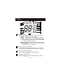
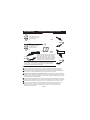
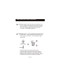
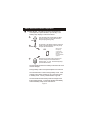
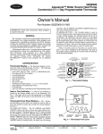
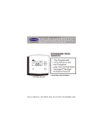
P/N 50QE900-250FS
OWNER'S MANUAL
AQUAZONE
Programmable
Digital Thermostat
I2:00
Am
72
Mo
74
COOL
AUTO
70
HEAT
Mounts Flush to the Wall
7 Day Programmable
3 Occupied, 1 Unoccupied
Auto Changeover
Large, Easy To Read Display
Thermoglow Backlight
Remote Sensor Ready
Dry Contact Equipped
Energy Saving Smart Fan
Fan Purge, IAQ Feature
Includes Locking Cover
Meets California Title 24
Designed for Commercial Water Source Heat Pumps
Commercial Systems & Services
Carrier Corporation 3/00
Table Of Contents
FRONT PANEL
DISPLAY
QUICK START Set the clock and go
BASIC OPERATION
PROGRAMMING Occupied / Unoccupied
ADVANCED SETUP
ABOUT ADVANCED OPERATION
WARRANTY
2
3
5
6
8
12
17
23
CAUTION
Follow Installation Instructions before proceeding.
SET THERMOSTAT TO MODE “OFF” PRIOR TO
CHANGING SETTINGS IN SETUP OR RESTORING
FACTORY DEFAULTS.
Commercial Systems & Services
Carrier Corporation 3/00
P/N 50QE900-250FS
Page 1
Front Panel
1
5
3
2
4
6
1
Liquid Crystal Display
2
Up/Down Buttons
3
Mode Button
4
Override Button
5
Heat or Cool Indicator
with Thermoglow
Heat = Red, Cool = Green
6
Temperature Sensor Bubble
Page 2
Display
2
6
3
1
8
I2:00
7
11
Am Start
Pm Stop
88
SuMoTuWeThFrSa Setup
unoccupied 123
COOL
10
Locked
Override
AUTO
ONOFF
Program On
Service Filter
Fan On
88
4
88
HEAT
1
5
1
1
1
4
9
1
Mode Indicators
Selects the operation mode of the equipment.
HEAT - indicates the heat mode.
COOL - indicates the air conditioning mode.
AUTO - indicates the system will automatically
changeover between heat and cool modes
as the temperature varies.
OFF - indicates the entire system is turned off.
PROGRAM ON - indicates the stored program
is enabled to run. Page 6.
2
Clock with Day of the Week
Indicates the current time and day. This clock is
also used to program the timer periods. Page 5.
3
Room Temperature Display
Indicates the current room temperature.
4
Desired Set Temperature
Indicates desired room temperature(s). Page 7.
Page 3
Display
5
Override Indication
Indicates the current program is currently being
overridden for up to 4 hours. Page 7,17.
6
Occupied or Unoccupied Indication
Indicates the program number: Occupied 1,2,3,
or Unoccupied. Page 8-11.
7
Setup Indication
Indicates the thermostat is in the programming
mode. Page 12.
8
Fan Operation Indication
Fan On - indicates constant, continuous fan
operation.
When Fan On is not lit - indicates the fan will
only operate when necessary to heat or
to cool. Page 12.
9
Service Filter Indication
Service Filter indicates when the filter should
be serviced under normal conditions.
Appears after 0 - 1950 hours of blower
operation (adjustable). Page 14.
10
Locked Indication
Locked appears after the right combination of
buttons are pressed, rendering the buttons
inoperative. Page 19.
11
Start / Stop Indication
Start or Stop appears when programming
timer functions. Page 9.
Page 4
Quick Start Set the Clock and Go
MODE
OVERRIDE
I2:00
Press the Mode button.
While holding the Mode,
press the Override button
for 2 seconds to enter Setup
screens.
During Setup & Programming:
Pressing the Mode button
selects different flashing items.
(Represented in dark black)
Pressing the Up and Down
buttons will modify the flashing
selection.
I
Press
Su
2
To adjust the
clock or Day use
MODE
buttons.
Press both Mode and
Override buttons as
above to return to
normal operation.
MODE
OVERRIDE
The thermostat is preprogrammed from the
factory to operate 1 or 2 Stage equipment* without
the need for further programming. To optimize the
installation of this thermostat follow the instructions
in the Advanced Setup section.
Page 5
Basic Operation
Select Mode
I2:00
70
70
70
70
70
Pm
Mo
The HEAT setting indicates the
temperature the room has to
reach before the furnace will
turn on to heat the room.
I2:00
Pm
Mo
The COOL setting indicates the
temperature the room has to
reach before the air conditioner
will turn on to cool the room.
I2:00
Pm
Mo
AUTO will automatically select
heat or cool based on room
temperature demand.
I2:00
Program On will activate the
stored timer operation.
(occupied &
unoccupied periods.)
Pm
Mo
unoccupied 1
ProgramOn
I2:00
OFF indicates both heating
and air conditioning
systems are turned off.
69
72
HEAT
COOL
Press
72
MODE
COOL
AUTO
69
73
HEAT
Press
MODE
COOL
70
HEAT
Pm
Mo
Page 6
Press
MODE
OFF
Press
MODE
Basic Operation
Select Desired Temperature
I2:00
70
Pm
Mo
72
In any mode, adjust the
desired Set Temperature
with
COOL
AUTO
69
HEAT
buttons.
Pressing the up/down buttons in Auto mode will adjust both the heat and cool
set temperatures simultaneously.
Pressing the up/down buttons in Heat or Cool modes will adjust only the
heat or cool set temperature.
Press
Override
I2:00
OVERRIDE
65
Pm Stop
Su
unoccupied
ProgramOn
I2:00
0:30
74
Pm
73
Pm
Su
occupied 1
ProgramOn
COOL
85
COOL
55
HEAT
During programmed, unoccupied periods
a press of the Override button will force
the thermostat into Occupied 1 comfort
settings, temporarily.
With each successive push of the Override
button, the override timer will add 30
minutes, until the maximum of 4 hours is
reached. Then the next press will zero out
the override timer, returning to unoccupied
if there are no further button presses.
When in Override, the Override icon and
the Occupied 1 icon appear on the display.
The time of day clock alternates with the
time remaining in override.
Override
72
HEAT
During Override, the setpoints are
adjustable, provided the keypad is not
locked.
Page 7
Programming
MODE
Occupied & Unoccupied Periods
Press the Mode button. While holding the Mode,
press the Up button for 2 seconds to enter
time period programming.
occupied 1
Select the maximum # of
occupied periods to be
used on any one day.
Typically 1.
(1,2 or 3)
Press
74
occupied 1
Adjust the cooling
setpoint for occupied 1.
MODE
COOL
(35 - 99 )
Press
MODE
74
occupied 1
Adjust the heating
setpoint for occupied 1.
COOL
(35 - 99 )
72
85
HEAT
Adjust the cooling
setpoint for unoccupied
periods.
(35 - 99 )
unoccupied
Press
MODE
COOL
Press
MODE
Continued
Page 8
Programming
Occupied & Unoccupied Periods
Adjust the heating setpoint for unoccupied
periods.
unoccupied
(35 - 99)
Select the day for
Occupied 1.
(M - S)
55
HEAT
Press
MODE
Mo
occupied 1
Press
MODE
7:00
Adjust the start time
for occupied 1.
Am Start
Mo
occupied 1
Press
MODE
6:00
Adjust the stop time
for occupied 1.
Pm Stop
Mo
occupied 1
Press
MODE
On
Select Occupied 1 to run
on this day (On), or not to
run this day (Off).
Mo
occupied 1
ON
Off
Press
MODE
Page 9
Continued
Programming
Occupied & Unoccupied Periods
The copy command becomes available after the maximum # of
occupied periods are programed in a day. This example uses 1
as the maximum occupied periods ever programed in one day.
Yes
Select Yes or No to copy
the previous day’s
program to this day.
No
No
Co
Tu
If Yes is selected:
Py
Selecting Yes, then pressing mode will copy the
previous day’s program and then will ask the
same copy question again. If yes is selected
each time, this routine will repeat until Saturday
is copied to Sunday. After Saturday is copied
to Sunday, the copy command is unavailable.
Press
MODE
Select the day
for Occupied 1.
If No is selected:
Press
MODE
Tu
occupied 1
(T - M)
Press
MODE
9:00
Adjust the start time
for occupied 1.
Am Start
Tu
Occupied 1
Press
MODE
5:00
Pm Stop
Tu
Occupied1
Adjust the stop time
for occupied 1.
Press
MODE
Page 10
Continued
Programming
Occupied & Unoccupied Periods
On
Select Occupied 1 to run
on this day (On), or not to
run this day (Off).
Tu
Occupied 1
OFF
Off
Press
MODE
No
Yes
Select Yes or No to copy
the previous day’s
program to this day.
No
If Yes is selected:
Press
MODE
Co
We
Py
Selecting Yes, then pressing mode will copy the
previous day’s program and then will ask the
same copy question again. If yes is selected
each time, this routine will repeat until Saturday
is copied to Sunday. After Saturday is copied
to Sunday, the copy command is unavailable.
If No is selected:
Press
MODE
If no is selected, as in previous steps flashing prompts for input will appear for
start and stop times for Occupied 1. If more than one occupied period was
selected in step 1 on page 8, then cool/heat setpoints, and start/stop times
for additional occupied periods will be prompted.
PROGRAMMING NOTES
If only 1 Occupied period is selected in step 1 on page 8, Occupied 2 & 3 programming steps are
skipped. Further, if only 2 occupieds are selected, Occupied 3 programming steps are skipped.
Heat & Cool setpoints for Occupied 1 are the same for every day of the week. Heat & Cool setpoints
for Occupied 2 & 3 can be adjusted differently for each day of the week, if desired.
If the start time is set later in the day than the stop time, the program will run from the start time to
midnight and from midnight to the stop time on the same day. For example: 9:00pm start, 8:00am stop,
on Monday. In this example the program will run from 12:00am Monday to 8:00am Monday and again
from 9:00pm Monday to 12:00pm Monday.
The Unoccupied settings take effect at all times when: (1) the program is on and (2) the current time is
outside a preset occupied period. For this reason start and stop times aren’t necessary for unoccupied.
If the same start and stop times are programmed in for an occupied period, then it will run 24 hours.
If one occupied period starts and stops within another occupied period the lower occupied # has
priority. For example: If Occupied 3 is programmed to be “on” 24 hours, and Occupied 2 is
programmed to run that day, then Occupied 2 settings will take over from occupied 3 between
Occupied 2 start and stop times.
Page 11
Advanced Setup
MODE
OVERRIDE
Press the Mode button.
While holding the Mode,
press the Override button
for 5 seconds to enter Setup
screens.
NOTE: Each step # is located at
the top right corner of the
display for easy reference.
I2:00
Am
Setup
I
Adjust the time of day
clock.
Tip: To change hours quickly, press and
hold the override button in and press
the up or down buttons.
Press
Mo
Setup
2
MODE
Select the day of the
week.
Press
0
Press
OVERRIDE
Setup
3
MODE
Reset the Service Filter
counter to 0, to remove
the icon from the display.
Press
Service Filter
Adjust the number of
hours the blower will
run before the Service
Filter icon appears on
the display. 0 = off.
500
Setup
4
MODE
Press
(0 - 1950)
MODE
Service Filter
Page 12
Continued
Advanced Setup
Fan On
Setup
Select fan operation,
Fan On or Fan Auto.
5
AUTO
Press
Fan Auto
Fan
MODE
88
2
2
6
Pu
Setup
Adjust the deadband
from 1 - 6 degrees.
Adjust the minimum
difference between
cooling & heating
setpoints.
(0 - 6 )
Select the cycles per
hour limit.
d=cycles per hour
limit defeated.
d1=d + defeat 5 min.
Compressor lockout.
(d, d1, 2 - 6)
81f
Setup
Setup
0:00
Setup
Adjust the preoccupancy
fan purge timer.
0 - 3 hours.
0:00 = off
Page 13
6
Press
MODE
7
COOL
HEAT
8
Cy
9
Press
MODE
Press
MODE
Press
MODE
Continued
Advanced Setup
On
Select the display backlight always On, or Off
after 8 seconds.
Off
Select the unit ID for
‘Soft Start’. This is used
in multiple installs to
stagger equipment turn
on times. 0 = off.
Each # = 30 second delay.
(0 - 99)
LI
Setup
Sof
ON
Select thermostat
operation in degrees
Fahrenheit or Centigrade.
F
Yes
Select the sensor type:
Yes = Outside or Duct
sensor
No =Automatic Detection
of Remote Sensor
Press
MODE
Start
0
F
Setup
Setup
C
I0
No
Setup
II
Press
MODE
I2
Press
MODE
I3
Press
No
MODE
To view Outside or Duct temperature
press and hold Mode 2 seconds, min.
The thermostat will not control to Outside or Duct Sensors.
Continued
Page 14
Advanced Setup
Sec
O
Setup
Select the security level:
0=no security in effect
1=setpoint range limited
2=1+ program on all times
3=2 + prohibits setpoint
changes
I4
Locked
Press
MODE
Adjust the maximum
allowable heat setpoint
when security is in effect.
(Step 15 only appears
if step 14 is not 0).
(35 - 99)
hi
80
Setup
I5
Locked
HEAT
Press
MODE
lo
Adjust the minimum
allowable cool setpoint
when security is in effect.
(Step 16 only appears
if step 14 is not 0).
(35 - 99)
65
Setup
I6
COOL
Locked
Press
MODE
Continued
Page 15
Advanced Setup
0
B
Setup
Select the reversing
valve polarity for
Heat Pump, O or B.
O
I7
Press
MODE
Press the Mode button.
While holding the Mode, press the Override
button for 2 seconds to leave the Setup
screens. If no buttons are pressed, the
display will leave the setup screens after
30 seconds.
OVERRIDE
Advanced Setup Table
Step #
1
2
3
4
5
6
7
8
9
10
11
12
13
14
15
16
17
Description
Range
Time of day clock set
Day of the week
Reset Service Filter icon
Service Filter run time set
Fan operation
Deadband or Temperature swing
Forced minimum difference heat/cool
Cycles per hour
Fan Purge timer
Thermoglow backlight
Soft Start
Fahrenheit or Centigrade
Outside/Duct Sensor
Security Levels
Maximum allowable Heat setpoint
Minimum allowable Cool setpoint
Reversing Valve polarity
Page 16
24 hour
Sun - Sat
-0 -1950
Auto / On
1-6
0-6
d, d1, 2 - 6
0:00 - 3:00
Off / On
0 - 99
F/C
Yes / No
0-3
35 - 99
35 - 99
O /B
Factory Default
12:00 Am
Monday
-500
Auto
2
2
6
0:00
On
0
F
No
0
80
65
O
About Advanced Features & Operation
CLOCK BACKUP - In the event of a power loss, the thermostat
internal clock will continue to keep proper time for a
minimum of 48 hours without external power or batteries.
2 STAGE OPERATION - The 2nd Stage of heat or cool is
turned on when (1) the 1st Stage has been on for a
minimum of two minutes, and (2) the temperature spread
from the setpoint is equal to or greater than: the setpoint
plus the deadband, plus 2 degrees.
Cooling
Heating
2 degrees
2nd Stage
turn on
1st Stage
turn on
Dead
Band
Heat
Setpoint
Dead
Band
Cool
Setpoint
2 degrees
1st Stage
turn on
2nd Stage
turn on
MINIMUM HEAT/COOL SETPOINT DIFFERENCE - The Heat
and Cool setpoints will not be allowed to come any closer
to each other than the value set in Advanced Setup step
# 7, on page 13. This minimum difference is enforced
during Auto changeover and Program On operation.
ENERGY SAVING SMART FAN - If Fan On is selected,
page 13, step 5, the fan will run continuously at all times,
except in Off, and will only run if there is a heating or
cooling demand in Unoccupied periods.
OVERRIDE - As explained on page 7, pressing the Override
button during a programmed, Unoccupied period will force
the thermostat into Occupied 1, temporarily, up to 4 hours.
If the Override button is pressed during an Occupied
period, the thermostat will be forced into Unoccupied and
the occupied # (1,2 or 3), it was forced out of will be
turned off, only for that day.
During Override periods the setpoints may be adjusted,
but they will not be remembered after Override ends.
Page 17
About Advanced Features & Operation
FAN PURGE TIMER - When this feature is activated, the fan
will turn on during Unoccupied at a preset amount of time
prior to Occupied 1. This preoccupancy fan purge timer
may be set as instructed on page 13, step #9, from
0 - 3 hours. 0 = this feature turned off.
EMERGENCY HEAT - To turn on Emergency Heat press in the
Override button. While holding the Override button press
the Up button for 2 seconds. The Cool setpoint display
will read ‘EH’.
I2:00
Press for
Emergency Heat
Am
73
Mo
eh
74
HEAT
OVERRIDE
During Emergency Heat the thermostat will turn
on the fan and the 2nd stage of heat, when there is a
demand for heat, locking out the 1st stage compressor.
Exiting Emergency Heat is the same as entering. During
Emergency Heat only OFF and HEAT are available.
Page 18
About Advanced Features & Operation
KEYPAD LOCK - To prevent unauthorized use of the thermostat,
the front panel buttons may be disabled. To disable, or
‘lock’ the keypad, press and hold in the Mode button.
While holding the Mode button in, press the Up and Down
buttons in together. The Locked icon will appear on the
display.
I2:00
Pm
We
unoccupied
85
COOL
Locked
Press all 3 for
Keypad Lockout
55
HEAT
On
MODE
To unlock the buttons, again press and hold the Mode
button. While holding the Mode button in, press the Up
and Down buttons in together. The Locked icon will
disappear from the display.
DRY CONTACT SWITCH - The terminals are ‘normally open’.
Closing or completing the circuit will cause the thermostat
to enter Occupied 1. This feature allows an external
device such as a Central Time Clock, Occupancy Sensor,
or a Telephone activated device to force 1 or more
thermostats into Occupied 1. For the Dry Contact to work
the thermostat must be in Program On. Set Occupied 1
to Off for all 7 days, so the Contact closure will be in
control. When the thermostat is forced into Occupied 1
via the Dry Contact closure, the icon Occupied 1 will blink.
CK1
GND
Page 19
Important Note: For control of multiple
thermostats by 1 source, refer to
document P/N 88-175 ‘Potential Phasing
Problems’ before installation.
About Advanced Features & Operation
HOLIDAY MODE - This feature forces the thermostat into
Unoccupied for a preset duration, up to 99 days. The
Holiday setup display is entered as follows:
1
MODE
2
OVERRIDE
Press the Mode button. While holding the Mode,
press the Up button for 2 seconds to enter the
time period programming setup.
The first step on the display prompts for maximum
number of Occupied periods. Ignore this prompt
and press the Override button.
hol
0
3
When active
the display
counts down
remaining days
blinking.
Unoccupied also
appears.
Press the Up or Down buttons to select the
number of days the thermostat will be in
Holiday mode. 0 = Off. To exit Holiday setup,
press the Mode button.
The thermostat will enter the Holiday mode when the clock
crosses midnight.
During Holiday mode Unoccupied setpoints are enforced.
The Override button is active during Holiday mode. It will
override to Occupied 1 settings up to 4 hours then return
to Holiday mode. The Dry Contact Switch is ignored.
The thermostat will exit Holiday mode at midnight of the
final programmed day. To terminate Holiday immediately,
enter the Holiday setup screen and select 0.
Page 20
About Advanced Features & Operation
SOFT START - This feature is utilized in multiple thermostat
installations controlled by the Dry Contact terminals.
Assigning a unique Soft Start number to each thermostat
will stagger the turn on times, even though the Dry
Contact closes, for all the thermostats connected, at the
same time. Each Soft Start number represents a multiple
of 30 seconds from the Dry Contact closure.
For example, #1 = turn on 30 seconds after Dry Contact
closure, #2 = turn on 60 seconds after closure, #3 = turn
on 90 seconds after closure, and so on. See page 14,
step 11, to configure the thermostat for Soft Start.
DUAL SETPOINT BEHAVIOR - The adjustable setpoint range
is: 35 - 99 degrees in Fahrenheit and 7 - 35 degrees in
Centigrade. When in the modes Heat or Cool, this
adjustable range is unhampered.
When adjusting any Auto mode, including programming
Occupied and Unoccupied periods, the thermostat will not
allow the Heat setpoint to get closer to the Cool setpoint
than the value programmed as the minimum difference in
step 7, page 13.
When entering the Auto mode from Cool, the Heat and
Cool setpoints will remain spread apart by the amount
that they were adjusted, prior to entering Auto.
For example: If the Cool setpoint was set to 80 while
in the Cool mode and the Heat setpoint was adjusted to
70 while in the Heat mode, upon entering the Auto mode
the Heat and Cool setpoints would be 80 and 70. Both
setpoints would then move up and down together, (in this
example spread by 10 degrees), by pressing the up or
down buttons.
To move the Heat and Cool setpoints closer together,
enter the Cool or Heat mode by pressing the Mode button,
then adjust the setpoint(s) closer together. Heat is limited
to how close it can come to Cool by step 7, page 13.
Page 21
About Advanced Features & Operation
REMOTE SENSORS (Optional Accessory) - When connected
to terminals RS+5, RS, & GND on the back of the
thermostat, it will read the temperature from the Remote
Sensor and ignore the temperature sensor inside the
thermostat. The thermostat automatically recognizes
when a Remote Sensor is connected (setup step #13-No).
When reading the temperature from the remote, the degree
icon above the room temperature blinks once a second.
The Override button on the Remote
Sensor works slightly different than
the Override button on the front panel.
Each press of the ‘External’ Override
button adds 2 hours to the override
timer. If the timer was already active,
Optional
Remote Sensor
the first button press will round the
Optional R.F. Sensor
runtime to either 2:00 or 4:00.
Subsequent button presses will not wraparound as the
Override button on the thermostat does, so the 2nd or
greater button press will set the runtime to 4:00. The
Locked feature has no effect on the external Override
button. The wired Remote Sensor is connected to the
thermostat with up to 500’ of 20 ga. or 300’ of 18 ga.
thermostat wire. See the Remote Sensor instructions for further details.
OVER
RIDE
OVER
RIDE
FACTORY DEFAULTS - If, for any reason it is desirable to
return all stored settings back to the factory default
settings, press the Mode button. While holding the Mode
button in, press the Down button for 2 sec. All icons will
appear. Press and hold in the Override button until Fd
appears. This resets all factory settings. To calibrate
room temperature, press the Mode button once more.
At this point use the Up and Down buttons to calibrate
room temperature, if needed. Press the Mode button to
return to normal operation. NOTE CAUTION ON PAGE 1.
Page 22
Warranty
One-Year Warranty - This Product is warranted to be free from defects in material and
workmanship. If it appears within one year from the date of original installation, whether or not
actual use begins on that date, that the product does not meet this warranty, a new or
remanufactured part, at the manufacturer’s sole option, to replace any defective part will be
provided without charge for the part itself; PROVIDED the defective part is returned to the
distributor through a qualified servicing dealer.
THIS WARRANTY DOES NOT INCLUDE LABOR OR OTHER COSTS incurred for diagnosing,
repairing, removing, installing, shipping, servicing or handling of either defective parts or
replacement parts. Such costs may be covered by a separate warranty provided by the installer.
THIS WARRANTY APPLIES ONLY TO PRODUCTS IN THEIR ORIGINAL INSTALLATION
LOCATION AND BECOMES VOID UPON REINSTALLATION.
LIMITATIONS OF WARRANTIES – ALL IMPLIED WARRANTIES (INCLUDING IMPLIED
WARRANTIES OF FITNESS FOR A PARTICULAR PURPOSE AND MERCHANTABILITY) ARE
HEREBY LIMITED IN DURATION TOT THE PERIOD FOR WHICH THE LIMITED WARRANTY
IS GIVEN. SOME STATES DO NOT ALLOW LIMITATIONS ON HOW LONG AN IMPLIED
WARRANTY LASTS, SO THE ABOVE MAY NOT APPLY TO YOU. THE EXPRESSED
WARRANTIES MADE IN THIS WARRANTY ARE EXCLUSIVE AND MANY NOT BE ALTERED,
ENLARGED, OR CHANGED BY ANY DISTRIBUTOR, DEALER, OR OTHER PERSON
WHATSOEVER.
ALL WORK UNDER THE TERMS OF THIS WARRANTY SHALL BE PERFORMED DURING
NORMAL WORKING HOURS. AL REPLACEMENT PARTS, WHETHER NEW OR
REMANUFACTURED, ASSUME AS THEIR WARRANTY PERIOD ONLY THE REMAINING
TIME PERIOD OF THIS WARRANTY.
THE MANUFACTURER WILL NOT BE RESPONSIBLE FOR:
1. Normal maintenance as outlined in the installation and servicing instructions or owners
manual including filter cleaning and/or replacement and lubrication.
2. Damage or repairs required as a consequence of faulty installation, misapplication, abuse,
improper servicing, unauthorized alteration or improper operation.
3. Failure to start due to voltage conditions, blown fuses, open circuit breakers or other
damages due to the inadequacy or interruption of electrical service.
4. Damage as a result of floods, winds, fires, lightning, accidents, corrosive environments or
other conditions beyond the control of the Manufacturer.
5. Parts not supplied or designated by the Manufacturer, or damages resulting from their use.
6. Manufacturer products installed outside the continental U.S.A., Alaska, Hawaii, and
Canada.
7. Electricity or fuel costs or increases in electricity or fuel costs from any reason whatsoever
including additional or unusual use of supplemental electric heat.
8. ANY SPECIAL INDIRECT OR CONSEQUENTIAL PROPERTY OR COMMERCIAL
DAMAGE OF ANY NATURE WHATSOEVER. Some states do not allow the exclusion of
incidental or consequential damages, so the above may not apply to you.
This warranty gives you specific legal rights, and you may also have other rights which may vary
form state to state.
Page 23
P/N 88-252