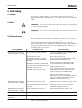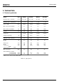
1
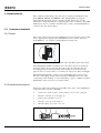
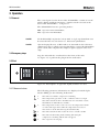
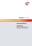
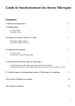
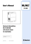
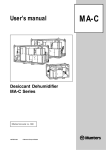
User’s manual
Cooling Dehumidifier
MK-series
Effective from serial No. 227789 990319
TGB-1028
© Munters Europe AB 2001
MK
MK Dehumidifier
2
TGB-1028-01.12
MK Dehumidifier
Contents
1. Introduction
1.1 General ......................................................5
1.2 Unpacking of the unit .................................5
1.3 Method of operation ...................................5
1.4 Transport instructions .................................5
1.5 Safety .........................................................6
1.6 Marking ......................................................6
2. Installation
2.1 General. .....................................................7
2.2 Placing of the unit .......................................7
2.3 Electrical connection ..................................7
2.4 Condensate drain .......................................8
2.5 Connection of humidistat ............................8
3. Operation
3.1 General ......................................................9
3.2 Emergency stops .......................................9
3.3 Start ...........................................................9
3.4 Stop ............................................................10
3.4 Emptying the water container .....................11
4. Maintenance
4.1 General ......................................................12
4.2 Safety .........................................................12
4.3 Maintenance schedule ...............................12
5. Fault finding
5.1 General ......................................................13
5.2 Safety .........................................................13
5.3 Fault localization.........................................13
6. Technical Data
6.1 Technical specification ................................14
TGB-1028-01.12
3
MK Dehumidifier
Important user information
Intended use of equipment
Safety
The MK-series cooling dehumidifiers are to be used
for dehumidification of air. All other use of the
equipment, or use which is contrary to the instructions
given in this manual, can cause personal injury and/or
machine damage.
About this manual
This manual describes the preparation for operation,
maintenance and fault finding.
The goal of the manual is to provide the necessary
information for the understanding of the unit ’s
construction and function, and to serve as a guide
during installation operation, maintenance and basic
trouble shooting.
Warranty and obligations
The warranty period is 12 months from the date the
equipment left our factory unless otherwise advised in
writing. The warranty is limited to a free exchange
complete with free freight, of faulty units or
components which have failed as a result of faulty
quality or defects in manufacture.
Munters guarantees that the delivered unit has
undergone rigid testing to ensure that the
specifications stated here are fulfilled. All claims on
warranty must verify that the fault has occurred within
the guarantee period, plus that the unit has been used
within its operating range as stated in the
specification. All claims must include the unit type and
manufacturing number. This data is to be found
stamped on the unit identification plate, see section
1.5 Marking for location.
Note
The contents in this publication can be changed
without prior notice.
This publication contains information which is
protected by copyright laws. No part of this
publication may be reproduced, stored in a system for
information retrieval or be transmitted in any form, in
any manner, without Munters’ written consent.
Please send any comments regarding the content of
this publication to:
Munters Europe AB
Dehumidification Division
Technical Publications
P O Box 434
SE-191 24 Sollentuna
Sweden
Tel: +46 (8) 626 63 00
Fax: +46 (8) 626 63 65
© Munters Europe AB 1999
4
NOTE!
WARNING! is used in this publication to indicate a possible danger that
could lead to personal injury. An
instruction is normally given, followed
by a short explanation plus the possible
effect if the instruction is not followed.
CAUTION! is used in this publication to indicate a possible danger that
could lead to damage to the machine or
other equipment and/or cause
environmental damage. An instruction
is normally given, followed by a short
explanation plus the possible
environmental effect if the instruction is
not followed.
is used to accentuate supplementary
information that is required for
problem-free use or optimal use of the
unit.
Conformity with directives and standards
MK-series is designed and manufactured by an EN-ISO
9001 accredited development and manufacturing
organisation. The units conform with the
specifications in European machine directive 89/392/
EEC, the low voltage directive 73/23/EEC and EMC
directive 89/336/EEC. The following design
standards have been applied:
• EN 292-1/-2
- Machine safety, basic concepts,
general principles for design.
• EN 60335-2-40 - Machine safety, electrical
equipment of machines.
• EN 1050
- Machine safety, risk analysis.
• EN 50081-1
- Electromagnetic compatibility,
general emission standard, public
environment.
• EN 50082-2
- Electromagnetic compatibility,
general resistance standard
industrial environment.
TGB-1028-01.12
MK Dehumidifier
1. Introduction
1.1 General
The Munters MK-series dehumidifiers are available in four (4)
different sizes and they can easely be moved to locations where
dehumidification of air is required.
1.2 Unpacking of the unit
The MK 300 has to be lifted vertically out of the packaging if you do
not want to damage the packaging. The MK 450, MK 800 and MK
1000 can be rolled out after having tilted the packaging.
After the handle is fitted the unit is ready to use.
1.3 Method of operation
The dehumidifiers type MK work in accordance with the condensation
principle.
Figure 1-1 shows the principle in the cooling circuit. The humid air is
drawn in by a fan. The air passes through a filter and is cooled down
on the evaporator
. This will bring the air temperature down
below the dew point and then the water vapour condenses to droplets
on the evaporator.
The droplets fall onto a condensate tray and are led to a water
container (MK300, MK450, MK800) or to a drain (MK1000).
The cold air is then led through the condenser
where it is
reheated. This heat comes from the condensation process and from
the energy of the compressor and the fan, which is turned into heat.
Therefore the air leaves the dehumidifier at a temperature which is
higher than at the entrance.
The approx. increase in temperature is 5°C.
The continuous air circulation through the unit reduces the relative
humidity giving rapid but gentle drying.
Figure 1-1 Principle of the cooling process
1.4 Transport instructions
The MK 300 has to be transported in vertical position. If the unit is
laid down during transport, the compressor may be damaged, and oil
from the compressor may get into the cooling circuit.
These precepts do not apply for MK 450, MK 800 and MK 1000, as
these units are fitted with rotary compressors.
TGB-1028-01.12
5
MK Dehumidifier
1.5 Safety
Information given in this manual are suggested best working practice
and shall in no way take precedence over individual responsibilities
and/or local rules and regulations.
Great effort has been placed on the design and manufacture of the
various sections of the unit so that it will comply with all applicable
safety aspects for this type of equipment. During operation it is always
each individual person’s responsibility to consider:
•
Their own and others’ personal safety.
•
The safety of the unit through correct use of the equipment in
accordance with the descriptions and instructions given in this
manual.
WARNING! The dehumidifier must be connected to an earthed electrical
outlet.
WARNING! The dehumidifier must not be connected to other mains than
specified on the unit’s identification plate.
WARNING! The dehumidifier must not be opened by anyone other than
trained and qualified personnel.
1.6 Marking
1.6.1 Location
Figure 1-2. Identification plate location
1.6.2 Identification plate
Figure 1-3. Identification plate content
6
TGB-1028-01.12
MK Dehumidifier
2. Installation
2.1 General
The MK Dehumidifiers are intended for indoor installation.
If the unit is stored prior to installation, place it in a roofed area, on a
level surface where it is protected from impact, dust, frost, rain or
aggressive contiminants.
2.2 Placing of the unit
If possible the dehumidifier should be placed in the middle of a room
to ensure a good air circulation.
The air should be sucked in freely at the back of the unit and blown
out at the front.
It is important that the dehumidifier is not installed near a source of
heat as for example a radiator, and doors and windows must be kept
closed.
Figure 2-1. Minimum distances to walls
2.3 Electrical connection
2.3.1 General
The unit is complete with plug and power cable for connection to an
earthed outlet. The voltage and frequency are specified on the unit’s
identification plate.
2.3.2 Safety
WARNING! The dehumidifier must be connected to an earthed electrical
outlet.
WARNING! The dehumidifier must not be connected to other mains than
specified on the unit’s identification plate.
WARNING! The dehumidifier must not be opened by anyone other than
trained and qualified personnel.
TGB-1028-01.12
7
MK Dehumidifier
2.4 Condensate drain
The condensate discharge into the water container included for the
units MK300, MK450 and MK800. The dehumidifier is stopped
automatically when the water container is full. Switch the on-off
schwitch to off position before emptying the water container. The MK
1000 has no water container and therefore a hose (Ø 16 mm)must be
connected to the drain outlet.
2.5
Connection of humidistat
2.5.1 General
The connection socket for the humidistat is located at the power cable
entry. Appropriate plug for the humidistat socket can be ordered
from Munters , see section 2.5.2 Humidistat connection kit
Figure 2-2 Power cable entry, Humidistat socket and Man/Auto mode switch
The humidistat shall be mounted 1–1.5 m. above the floor and positioned so that it is not exposed directly to dry air from the unit or
incoming moist air from opening and closing doors. It may not be
placed close to a heat source or so that it is exposed to direct sunlight.
The humidistat shall be a single stage humidistat and connected so
that the controlling circuit closes as relative humidity increases. The
connecting cable shall be screened and have copper conductors with a
minimum cross-section area of 2 x 0.75 mm2.
2.5.2 Humidistat connection kit
Follow the instructions below to assembly and connect the humidistat
connection kit. (Art. No. 24039E)
1.
Connect the leads to pins 1 and 2, and the screen to the earth pin.
2.
Affix the terminal (2) to the plug (1).
3.
Tighten the terminal screws (3).
4.
Affix the cover (4) to the plug (1).
5.
Affix the flange (5) to the cover (4).
Figure 2-3 Humidistat connection kit assembly
8
TGB-1028-01.12
MK Dehumidifier
3. Operation
3.1 General
The control panel on the front of the dehumidifier consists of on-off
switch, display and hour run meter. A mode switch is located at the
back of the dehumidifier, see Figure 2-2
The dehumidifier has two operating modes :
Man Operation without humidistat.
Auto Operation with humidistat
NOTE!
For the dehumidifier to function in Auto mode, a single stage humidistat must
be connected to the unit. See Section 2.5, Connection of humidistat.
NOTE!
After each stop of the unit, in Man mode or in Auto mode or due to the water
stop function, there is a built-in function that delays re-start of the dehumidifier
for 45 seconds. This will protect the compressor against frequent starts and
stops.
3.2 Emergency stops
Stop the unit with the on-off switch at the front of the unit,
see Figure 3-1, or pull out the plug from the wall outlet.
3.3 Start
Figure 3-1. Control panel - on-off switch, display and hour run meter
3.3.1 Measured values
The following parameter information are displayed and the light
diodes (LED) give the following indications:
1.
The unit is on and the compressor is running.
2.
The temperature/pressure on the condenser side is too high.
The unit is switched off for 45 minutes before automatic restart.
The LED is on and indicates a failure.
3.
The temperature in the room is too low. At temperatures under
+3°C the unit stops. If the ambient temperature increases to
more than +3°C the unit starts again automatically.
4.
The unit is switched off beacause the water container is full.
5.
The unit is in defrosting mode. During defrosting the
compressor is working and the fan is stopped.
6.
The evaporator is icing up.
o
3C
TGB-1028-01.12
9
MK Dehumidifier
3.3.2 Manual operation
1.
Switch the on-off switch to position I, see Figure 3-1.
2.
Select the MAN operating mode with the MAN-AUTO switch, see
Figure 2-2.
Fan and compressor start. The light diod No. 1 on the display lights
up. The unit now operates continuously, independently of the relative
humidity in the room. The unit is switched off by turning the on-off
switch to position 0.
3.3.3 Automatic operation
For the dehumidifier to operate in the Auto mode , the humidistat
must be connected to the humidistat socket of the unit, see Section 2.5,
Connection of humidistat.
1.
Adjust the humidistat to the desired setpoint.
2.
Switch the on-off switch to position I, see Figure 3-1.
3.
Select the Auto operating mode with the MAN-AUTO switch, see
Figure 2-2.
If the relative humidity of the room is higher than the humidistat setpoint, the unit starts to dehumidify. When the relative humidity of the
air is equal to the set-point of the humidistat, the unit switches off
automatically. If the humidity of the air increases again, the unit is
switched on again by the humidistat
If the dehumidifier is to be turned off completely, for example if the
water container is to be emptied, the on-off switch must be set at
position 0.
NOTE!
The opening and closing of the humidistat circuit within the 45 seconds period
will not start the dehumidifier again because of the delay function. The purpose
with this function is to prevent the dehumidifier from continuously cycling on
and off, in the event the humidistat is installed in a poorly choosen location.
3.3.4 Hour run meter
The hour run meter indicates accumulated number of hours the
dehumidifier has been in dehumidifying operation. The two digits to
the right indicates percent of one hour e.g. 0000475 should be read as
four hours and 45 minutes. The hour run meter is not re-setable.
3.4 Stop
Switch the on-off switch to position 0, see Figure 3-1.
10
TGB-1028-01.12
MK Dehumidifier
3.5
Emptying the water container
As mentioned in section 2.4 the unit has to be switched off before
taking out the water container. When taking out the water container,
press it slightly inwards to disengage the cut of the water container
from the edge. When reinserting the water container care must be
taken not to place the container in a position which switches off the
automatic water stop function, see Figure 3-2.
Figure 3-2. Position of the water container
TGB-1028-01.12
NOTE!
If the water stop function is switched off the water in the container will run
over.
NOTE!
After each stop of the unit by the water stop function, here is a built-in function
that delays re-start of the dehumidifier for 45 seconds.
11
MK Dehumidifier
4. Maintenance
4.1 General
The dehumidifier is designed for long, continuous operation with a
minimum of attendance. Under normal operating conditions, requirements for maintenance are minimal.
Maintenance interval lengths are primarily determined by operating
conditions and the environment in which the unit is installed. When
in doubt, consult Munters’ product service department. See addresses
for Munters representatives on the back cover of this manual.
4.2 Safety
WARNING! The unit must not be opened by anyone other than trained and
qualified personnel.
4.3 Maintenance schedule
The unit design allows for required maintenance actions to be carried
out from the outside without the need for opening the unit.
The following maintenance schedule is recommended by Munters and
covers procedures for inspection and maintenance as well as suggested
time intervals for a unit that operates under normal operational and
environmental conditions.
If the inlet process air has a high dust content, preventative scheduled
maintenance should be performed at shorter intervals than what is
specified below.
Com ponent
Inspection/m aintenance
3-6 m onths
12 m onths
Process filter 1
Clean filter. It can be rinsed in lukewarm soapy
water or, if not very dirty, cleaned with a
vacuum cleaner.
Clean filter housing and change filter (EU3).
Dehum idifier, outside
Check for physical dam age and clean unit
exterior if necessary.
Check for physical dam age and clean unit
exterior if necessary.
Contact M unters’ product service departm ent
as required.
Hum idistat
-
Check sensor functions and calibrate if
necessary.
Contact M unters’ product service departm ent
as required.
1)Filter mesh is removed by moving the upper part outwards.
Table 4-1. Maintenance schedule
12
TGB-1028-01.12
MK Dehumidifier
5. Fault finding
5.1 General
The purpose of this chapter is to provide guidance in basic fault
finding and provide instructions for corrective actions so as to remedy
faults.
5.2 Safety
WARNING! The unit must not be connected to other mains than specified on
the units identification plate.
WARNING! The unit must not be opened by anyone other than trained and
qualified personnel.
5.3 Fault localization
The unit design allows for fault localization actions to be carried out
from the outside without the need for opening the unit.
Go through the following trouble shooting list before contacting
Munters’ product service department. The list provides help in identifying types of faults that are easy to remedy without the assistance of
specially trained personnel.
Fault symptom
Dehumidifier has stopped and
no fault indications are light up.
Possible cause
Corrective action
On-off switch turned off by mistake.
Place the on-off switch in the on position and
check that dehumidifier starts.
No mains power to unit.
Check mains power to unit.
Dehumidifier switched to automatic
mode by mistake with no humidistat
connected.
Set the operating mode switch to manual mode
and check that the dehumidifier starts.
Dehumidifier switched to manual mode
by mistake with a humidistat connected.
Set the operating mode switch to automatic
mode and check that the dehumidifier starts.
Reduce humidistat setpoint
Humidistat setpoint too high
Humidistat fault (automatic mode).
Set the operating mode to manual mode and
check that the dehumidifier starts. If the unit
starts, the humidistat is probably at fault.
Check the humidistat by seeing if the
dehumidifier starts when the humidistat setpoint
is reduced.
Reset the humidistat setpoint after the check.
Calibrate the humidistat if necessary.
Dehumidifier has stopped and
fault indication No 2. lights up
Roomtemperature is above +30°C
Wait until the room temperature is below +30°C
Pressure and temperature on the highpressure side of the cooling system is
too high.
Check filter and process air inlet for dirt or
blockage. Check that the fan is working.
Contact Munters product service.
Dehumidifier has stopped and
fault indication No 3. lights up
Room temperature is below +3°C.
Wait until the temperature is above +3°C
Dehumidifier has stopped and
fault indication No 4. lights up
The water container is full.
Empty the water container.
Dehumidifier capacity has
diminished
Fault in the cooling circuit.
Contact Munters product service.
Table 5-1. Fault localization
TGB-1028-01.12
13
MK Dehumidifier
6. Technical Data
6.1 Technical specification
Model
Type
MK300
MK450
MK800
MK1000
Working range - humidity
% R.H.
40 - 100
40 - 100
40 - 100
40 - 100
°C
3 - 30
3 - 30
3 - 30
3 - 30
V/Hz
230/50
230/50
230/50
230/50
Max. current consumption
A
2,7
2,9
4,1
6,9
Max. power consumption
W
600
700
950
1500
m³/h
280
400
800
1000
-
R 407C
R 407C
R 407C
R 407C
kg
0,3
0,475
0,575
1,6
l
5,5
12,5
12,5
- *)
kg
41
52
60
74
mm
mm
mm
486
546
991
596
580
1010
596
580
1010
686
607
1128
Max. noise level
dBA
58
60
62
65
Dehumidification capacity
at 20°C 60% RH
at 10°C 60% RH
l/24h
l/24h
7,7
3,0
18,0
7,2
28,8
11,5
36,0
15,6
Working range - temperature
Power supply
Air flow
Refrigerant
Refrigerant quantity
Capacity of water container
Weight
Dimensions
Width
including frame
Depth
handle and wheels
Heigh
*) Hose to be connected to drain outlet
Table 6-1. Specifications
14
TGB-1028-01.12
MK Dehumidifier
TGB-1028-01.12
15
ARGENTINA
Munters Argentina
BUENOS AIRES
Tel: +54 (0)11 4902 1874
Fax: +54 (0)11 4902 1823
CANADA
Munters Inc.
MISSISSAUGA
Tel: +1 905 858 5851
Fax: +1 905 858 9130
GERMANY
Munters GmbH
HAMBURG
Tel: +49 (0)40 7 341 601
Fax: +49 (0)40 7 341 6131
NEW ZEALAND
Munters Pty Ltd
AUCKLAND
Tel: +64 96 34 8241
Fax: +64 96 34 8237
SOUTH AFRICA
Munters (Pty) Ltd
JOHANNESBURG
Tel: +27 (0)11 455 2550/1/2
Fax: +27 (0)11 455 2553
THAILAND
Munters Co., Ltd
BANGKOK
Tel: +662 645 2708
Fax: +662 645 2710
AUSTRALIA
Munters Pty
NORTH ALBURY
Tel: +61 (0) 260 256 422
Fax: +61 (0) 260 258 266
CHINA
Munters Beijing Ltd
BEIJING
Tel: +86 (0)10 6942 9512
Fax: +86 (0)10 6942 9513
ITALY
Munters S.R.L.
ASSAGO (MI)
Tel: +39 0 2 488 6781
Fax: +39 0 2 488 1171
NETHERLANDS
Munters Vochtbeheersing
ALPHEN a/d RIJN
Tel: +31 (0) 172 43 32 31
Fax: +31 (0) 172 44 29 60
SPAIN
Munters Spain SA
MADRID
Tel: +34 (9) 1 640 0902
Fax: +34 (9) 1 640 1132
USA
Munters Corporation
AMESBURY
Tel: +1 978 241 1100
Fax: +1 978 241 1214
AUSTRIA
Munters Luftentfeuchtung
WIEN
Tel: +43 (0) 1 616 42 98
Fax: +43 (0) 1 616 42 98 98
DENMARK
Munters A/S
FARUM
Tel: +45 44 95 3355
Fax: +45 44 95 3955
JAPAN
Munters KK
TOKYO 174
Tel: +81 (0)3 5970 0021
Fax: +81 (0)3 5970 3197
SAUDI ARABIA
Hawa Munters
RIYADH
Tel: +966 (1)477 1514
Fax: +966 (1)476 0936
SWEDEN
Munters Europe AB
SOLLENTUNA
Tel: +46 (0)8 626 6300
Fax: +46 (0)8 754 8594
BELGIUM
Munters N.V.
AARTSELAAR
Tel: +32 (0) 3 458 2434
Fax: +32 (0) 3 458 2433
FINLAND
Munters OY
HELSINGFORS
Tel: +358 (0)9 8386 0330
Fax: +358 (0)9 8386 0336
KOREA
Munters
SEOUL
Tel: +82 (0)2 552 8770
Fax: +82 (0)2 552 8772
POLAND
Munters Poland Sp zoo
GDANSK
Tel: +48 58 305 35 17
Fax: +48 58 346 34 53
SWITZERLAND
Munters AG
ZÜRICH
Tel: +41 (0) 1 271 1013
Fax: +41 (0) 1 271 1019
BRAZIL
Munters Brasil
VILA EMILIANO PERNETA
Tel: +55 (0)41 868 2176
Fax: +55 (0)41 868 2105
FRANCE
Munters France S.A.
COLOMBES PRINCIPAL
CEDEX
Tel: +33 (0) 141 19 24 42
Fax: +33 (0) 141 19 00 32
MEXICO
Munters de Mexico S.A. de C.V.
GUADALUPE N.L.
Tel: +52 (9) 8 327 5990 to 93
Fax: +52 (9) 8 327 5994
SINGAPORE
Munters Pte Ltd
SINGAPORE
Tel: +65 744 6828
Fax: +65 744 9585
UNITED KINGDOM
Munters UK Ltd
HUNTINGDON
Tel: +44 (0) 1480 432 243
Fax: +44 (0) 1480 413 147