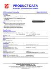
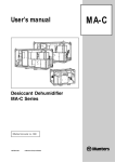
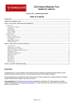
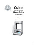
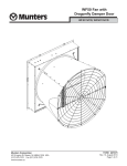
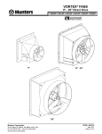
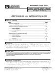
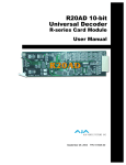
1
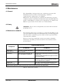
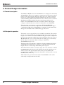
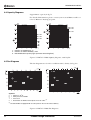
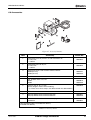
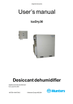
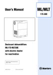
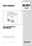
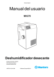
User’s Manual
Desiccant Dehumidifiers
MG50 & MG90
Effective from serial No. 31880
190TGB-1004
© Munters Europe AB 2005
MG
MG50/90 Dehumidifiers
Contents
Important user information ......................................4
1. Introduction
1.1
1.2
1.3
1.4
General ..........................................................5
About this manual ..........................................5
Safety and Cautions.......................................5
Markings ........................................................6
2. Installation
2.1
2.2
2.3
2.4
2.5
2.6
2.7
2.8
2.9
Safety.............................................................7
Packaging and delivery inspection.................7
Storing the equipment....................................7
Location requirements ...................................8
Duct/hose connections ..................................8
2.5.1 General ...............................................8
2.5.2 Ducting and airflow adjustment ..........9
Mounting units on the Wall...........................10
Installation examples ...................................11
Electrical connections ..................................13
2.8.1 General .............................................13
2.8.2 Safety................................................13
Connecting the humidistat ...........................13
3. Operation
3.1 Starting up ...................................................15
3.2 Emergency stop...........................................15
3.3 Start .............................................................15
3.3.1 Manual operation ..............................15
3.3.2 Automatic operation..........................15
3.4 Stopping the unit..........................................16
4. Maintenance
4.1 General ........................................................17
4.2 Safety...........................................................17
4.3 Maintenance schedule.................................17
5. Fault finding
5.1 General ........................................................18
5.2 Safety...........................................................18
5.3 Fault localization ..........................................18
6. Product Design Information
6.1
6.2
6.3
6.4
6.5
6.6
6.7
Product description ......................................20
Principal of operation ...................................20
Dimensions and service space ....................21
Capacity Diagrams.......................................22
Fan Diagrams ..............................................22
Accessories .................................................23
Technical Specifications...............................24
190TGB-1004-F05.05
Contents
3
MG50/90 Dehumidifiers
Important user information
Intended use of equipment
Safety
The MG50 & MG90 dehumidifiers are intended to
be used for the dehumidification of air. All other
uses of the equipment, or use which is contrary to
the instructions given in this manual, can cause
personal injury and/or machine damage.
In this publication hazardous activities are
indicated and preceded by the common hazard
symbol.
WARNING! is used in this
publication to indicate a possible
danger that could lead to personal
injury. An instruction is normally
given, followed by a short
explanation plus the possible effect if
the instruction is not followed.
Warranty and obligations
The warranty period is 12 months from the date
the equipment left our factory unless otherwise
advised in writing. The warranty is limited to a free
exchange complete with free freight, of faulty
units or components which have failed as a result
of faulty quality or defects in manufacture.
Munters guarantees that the delivered unit has
undergone rigid testing to ensure that the
specifications stated here are fulfilled. All claims
on warranty must verify that the fault has occurred
within the guarantee period, plus that the unit has
been used within its operating range as stated in
the specification. All claims must include the unit
type and manufacturing number. This data is to be
found stamped on the unit identification plate,
see Section Markings for location.
CAUTION! is used in this
publication to indicate a possible
danger that could lead to damage to
the machine or other equipment
and/or cause environmental
damage. An instruction is normally
given, followed by a short
explanation plus the possible
environmental effect if the
instruction is not followed.
NOTE!
Used to accentuate supplementary
information that is required for problemfree use or optimal use of the unit.
Note
The contents of this publication can be changed
without prior notice.
This publication contains information which is
protected by copyright laws. No part of this
publication may be reproduced, stored in a system
for information retrieval or be transmitted in any
form, in any manner without Munters’ written
consent.
Please send any comments regarding the content
of this publication to:
Conformity with directives and standards
The MG50 & MG90 dehumidifiers are designed and
manufactured by an EN-ISO 9001 accredited
development and manufacturing organization. The
unit conforms with the specifications in the Machinery
Directive 98/37/EEC, the Low Voltage Directive
73/23/EEC as amended by Directive 93/68/EEC and
the EMC Directive 89/336/EEC as amended by
Directives 92/31/EEC and 93/68/EEC . The standards
applied are listed in the EC Declaration of Conformity.
Munters Europe AB
Dehumidification Division
Technical Publications
PO Box 434
SE-191 24 Sollentuna
Sweden
Tel.: +46 (8) 626 63 00
Fax: +46 (8) 626 86 18
© Munters Europe AB 2005
4
Important user information
190TGB-1004-F
MG50/90 Dehumidifiers
1. Introduction
1.1 General
The MG50 and MG90 desiccant dehumidifiers are designed to
efficiently dehumidify air. Munters has a wide range of dehumidifiers
that have design parameters applicable for different usages and
applications. Please contact your nearest Munters office if you have any
doubt or questions regarding the actual installation.
For MG50/90 product data, see chapter 6. Product Design Information.
1.2 About this manual
This manual is written for the user of the dehumidifier and describes
the installation, operation, maintenance and basic fault finding.
The information structure of the manual is built on numbered chapters
and sections. Contents (page 3) gives a quick overview. The different
chapters can be used separately to serve their purpose. Figures and
tables are numbered in accordance with the actual chapter, e.g. figure
1-3 is picture number 3 and is found in chapter 1.
The goal of the manual is to provide the necessary information for the
user to understand the unit’s construction and function, and to serve as
a guide during installation, operation, maintenance and basic fault
finding that generally can be carried out before contacting Munters
Product Service.
1.3 Safety and Cautions
The contents of this manual include suggested best working practices
and procedures. These are issued for guidance only, they do not take
precedence over the individual responsibility and/or local safety
regulations. During installation and operation of this equipment it is
always each individual person’s responsibility to consider:
• Their own and others’ personal safety.
• The safety of the unit through correct use of the equipment in
accordance with the descriptions and instructions given in this
manual.
Every care has been taken in the design and manufacture of the MG50
and MG90 dehumidifiers to ensure that they meet the safety
requirements of the directives and standards listed in the EC
Declaration of Conformity.
It is recommended to be informed about the use of safety symbols in
this manual by reading the opposite page Important user information.
The relevant safety information for this manual will be found listed
early in each manual chapter.
190TGB-1004-F
Introduction
5
MG50/90 Dehumidifiers
1.4 Markings
Location of the unit
identification plate
Type MG50
Fabr. No 0214 190XXX XXXXX
1 ~ 230V 50Hz
M
0.040 kW
0,4 kW
Max
0,440 kW
IP44
Munters Europe AB
Figure 1-1. Identification plate location
The units Identification plate is located on the underneath of the
dehumidifier.
Type MG50
Fabr. No 0214 190XXX XXXXX
1 ~ 230V 50Hz
M
0.040 kW
0,4 kW
Max
0,440 kW
IP44
Munters Europe AB
Figure 1-2. Identification plate content
6
Introduction
190TGB-1004-F
MG50/90 Dehumidifiers
2. Installation
2.1 Safety
WARNING! The dehumidifier must be connected to an earthed electrical outlet.
WARNING! The unit must not be connected to other mains than specified on
the unit’s identification plate.
WARNING! The unit must not be opened by anyone other than trained and
qualified personnel.
CAUTION! If there is a risk for freezing temperatures, the wet air ducting must
be insulated.
CAUTION! We recommend that only a qualified electrician should connect the
humidistat to the cable.
WARNING! All electrical equipment connections must be carried out in
accordance with local regulations and by qualified personnel.
WARNING! Do not place the Wet Air side (A) and the back side (B) of the unit
close to the wall or close to heat sensitive objects. Position the dehumidifier so that
there is sufficient space for the air to circulate around it (see section 2.4. Location
requirements).
2.2 Packaging and delivery inspection
1. Check the delivery against the packaging list, consignment note or
other delivery documents and check that everything is included and
nothing is damaged.
2. Contact Munters immediately if delivery is not complete in order to
avoid installation delays.
3. If the unit is to be put into storage, prior to installation, see section
2.3. Storing the equipment.
NOTE!
If the installation is not to be carried out immediately after the arrival of the
equipment it is advisable to leave the packing material in place on the
dehumidifier, or to re-use the packaging material to provide temporary protection
for the unit during later transport to the installation location and during
installation.
4. Remove all packaing material from the unit, check carefully to make
sure that no damage has occured during transport.
5. Any visible damage must be reported in writing to Munters prior to
the start of installation.
2.3 Storing the equipment
The following is important if the dehumidifier is to be stored prior to
installation:
• Place the dehumidifier on a horizontal surface.
190TGB-1004-F
Installation
7
MG50/90 Dehumidifiers
• Protect the dehumidifier from physical damage.
• Store the dehumidifier under cover and protect from dust, frost,
rain and aggressive contaminants.
2.4 Location requirements
The unit should be placed in a upright position, inside or outside the
dehumidifiered space, and be at least 15 cm above the floor.
The dehumidifier is intended for indoor installation.
It is important that the intended installation site meets the location and
space requirements for the equipment in order to achieve the best
possible performance and trouble-free operation.
For unit and service dimensions, see section 6.3. Dimensions and service
space.
WARNING! Do not place the Wet Air side (A) and the back side (B) of the unit
close to the wall or close to heat sensitive objects. Position the dehumidifier so that
there is sufficient space for the air to circulate around it.
Front side
(A)
NOTE!
Back side
(B)
It is important, both for maintenance and for service, that the minimum
dimensions for service access are complied with.
2.5 Duct/hose connections
2.5.1 General
Follow the instructions below when ducts, or alternate flexible hoses
are attached to the unit’s air outlet connections:
Process and reactivation air inlets and the dry air outlet can be
connected to a duct system or operated with free suction and
discharge. The wet air outlet however, must always be connected to a
duct or hose which must be mounted so as to slope down from the
dehumidifier to allow drainage of condensate.
– Ducting shall be as short as possible so as to minimize static pressure
losses.
– For unrestricted performance, all duct connections must be air and
vapour tight.
8
Installation
190TGB-1004-F
MG50/90 Dehumidifiers
– Ducting for wet air shall be installed at a downward incline to enable
condensate to drain. The wet air ducting should be provided with
suitable drainage at low points to prevent the collection of
condensed water. Alternatively, condensation can be avoided by
insulating the duct with at least 25 mm of suitable insulating
material.
– Cover the duct opening with a net to prevent birds and vermin from
entering the unit. Place the duct opening so that rain and snow
cannot enter the ducting.
– Ducting for wet air should be corrosion resistant and able to
withstand temperatures of up to 70°C.
– The wet Air shall normally be transported outdoors. At large sites,
where the dehumidifier is placed outside of the space to be
dehumidified, the wet air can be discharged in the vicinity of the
unit. Place the outlet so that wet air does not blow towards moisturesensitive objects.
– The minimum distance between dry or wet air outlet and a wall is
0.5m.
The filters for both process and reactivation air can be changed with
the ducting connected.
CAUTION! If there is a risk of freezing temperatures, the wet air ducting must
be insulated.
2.5.2 Ducting and airflow adjustment
Reactivation air
The dehumidifier is equipped with two orifice plates (airflow
restrictions) in the reactivation air circuit.
One of which is located at the inlet to the reactivation air fan behind
the filter and inlet cone (This cannot be removed).
The second orifice(A), is located in the wet air outlet. This orifice plate
will provide correct airflow if a total of 5 m of hose is not exceeded for
reactivation and wet air. If the flexible hose exceeds 5 m (max 10 m)
the orifice plate (A) and wall pipe (optional extra) cannot be used.
When using a wall pipe (see section 6.6. Accessories)connected to the
hose, remove orifice (A).
Process air
The dry and process air hose may have a total length of up to 10 m
without any significant effect on the dehumidifying capacity.
Reduction of process airflow in a ventilating system (see figure 2-1.
Connection to ducting).
In order to obtain the required low humidity when the space is
ventilated with dry air, (“open system”) the dry airflow should be
reduced by fitting an orifice plate (B) inside the connection piece (C)
for the dry air outlet. This will increase the dehumidification capacity.
190TGB-1004-F
Installation
9
MG50/90 Dehumidifiers
The accessories (B) and (C) are optional extras. The connection piece
(C) allows the dry air outlet to be duct connected.
Item
D
C
E
B
Function
A1
Orifice plate for wet air.
B
Orifice plate used in a “ventilating system”.
C
Connection piece for dry air outlet.
D
Connection piece for process air inlet.
E
Connection piece for reactivation air inlet.
F
Wet air outlet.
1
Item included with delivery
Other items can be ordered as accessories, see
section 6.6. Accessories.
F
Table 0-1. Duct Functions
A
Figure 2-1. Connection to ducting
2.6 Mounting units on the Wall
The MG units can be placed on the wall in two ways using a wall bracket
(optional extra), thus enabling optimized positioning of the wet and
dry air outlets to meet any desired requirements.
1. One is to have the unit’s wet air outlet positioned close to the wall on
the right side of the unit.
2. The other is to have the front of the unit facing the wall, so that the
wet air outlet is positioned furthest away from the wall to the left side
of the unit.
Option 1 & 2 both have a strip of wood (or similar) placed inbetween
the wall bracket and the wall. This wood is required so that to enable
enough space for air to circulate around the units and to be able to
connect the humidistat plug (option 2).
Option 2
Option 1
A. Wall Bracket1
B. Wet Air Hose
C. Wall Pipe1
(Mounted with a down
slope towards the outside)
D. Wooden Distance:
Depth 30 mm
Width 40 mm
Length 350 mm
Dry Air
Outlet
Wet Air
Outlet
1Optional
extra
Figure 2-2. Wall mounted dehumidifiers.
10
Installation
190TGB-1004-F
MG50/90 Dehumidifiers
Figure 2-3. Wall Pipe
2.7 Installation examples
Closed Airflow System
The air in the space is recirculated through the dehumidifier.
1
The wet air outlet is connected to a hose and is then
discharged outside.
Reactivation air is taken from outside through a hose
connected to a connection piece.
NOTE! A short hose (~ 0.3 m) on the dry air outlet can
improve the air circulation and eliminate the risk
of short-circuiting dry air and process air.
2
Process air it taken from the dehumidified space
through a hose connected to a connection piece.
Dry air is supplied to the space through a hose
connected to a connection piece. First remove the
orifice plate (B) fitted in the connection piece.
190TGB-1004-F
Installation
11
MG50/90 Dehumidifiers
The wet air outlet is connected to a hose and is then
discharged outside.
3
Reactivation air is taken from the dehumidified
space.
NOTE! A short hose (~ 0.3 m) on the dry air outlet can
improve the air circulation and eliminate the risk
of short-circuiting dry air and process air.
Resulting dehumidifying capacity is 2/3 of the
diagram data, see section 6.4. Capacity Diagrams for
details.
Figure 2-4. Installation examples in a closed system.
Ventilating System
The space is ventilated with dehumidified air.
1
Dry air is supplied to the space through a hose
connected to a connection piece fitted with an
orifice plate (B) in order to obtain required
reduction of process airflow:
MG50 = 25 m3/h, MG90 = 45m3/h
12
Installation
190TGB-1004-F
MG50/90 Dehumidifiers
The wet air outlet is connected to a hose and is then
discharged outside.
Reactivation air and process air are taken from outside
through hoses and connection pieces.
2
Dry air is supplied to the space through a connection
piece fitted with an orifice plate (B) in order to obtain
required reduction of process airflow:
MG50 = 25 m3/h,MG90 = 45 m3/h
Figure 2-5. Installation examples in a ventilating system.
2.8 Electrical connections
2.8.1 General
Included with delivery is a 2.5m long power cable with a plug for
connection to an earthed outlet. The voltage and frequency are
specified on the unit’s identification plate.
2.8.2 Safety
WARNING! The unit must be connected to an earthed electrical outlet.
WARNING! The unit must not be connected to other mains than specified on
the unit’s identification plate.
2.9 Connecting the humidistat
The dehumidifiers are supplied with a pre-wired socket, suitable for
connecting the unit to a low voltage, single stage humidistat, see figure
below. The humidistat can be ordered as an optional extra.
Figure 2-6. Humidistat Cable Connecting plug
CAUTION! We recommend that only a qualified electrician should connect the
humidistat to the cable.
190TGB-1004-F
Installation
13
MG50/90 Dehumidifiers
The connection socket for the humidistat is located on the front of the
unit.
Humidistat
Socket
Figure 2-7. Humidistat Location
The humidistat should be mounted 1–1.5 m. above the floor and
positioned so that it is not exposed directly to dry air from the unit or
incoming moist air from opening and closing doors. It may not be
placed close to a heat source or so that it is exposed to direct sunlight.
The humidistat shall be a single stage humidistat and connected so that
the controlling circuit closes as relative humidity increases. The
connecting cable shall be screened and have copper conductors with a
minimum cross-section area of 2 x 0.75 mm2.
If the units are in conjunction with an external humidistat it can
operate in either A or B mode.
A mode: The humidistat controls the entire dehumidifier ON/OFF
(default mode).
B mode: The humidistat controls only the reactivation heater and the
fan continously operates ON/OFF.
At delivery the dehumidifier is connected to operate in the A mode.
To change the dehumidifier to B mode, move the link at S2 on the PCB
from A to B as shown in figure 2-8. PCB Board.
For the location of the PCB, see figure 6-1. Principal of operation.
WARNING! All electrical equipment connections must be carried out in
accordance with local regulations and by qualified personnel.
Figure 2-8. PCB Board
14
Installation
190TGB-1004-F
MG50/90 Dehumidifiers
3. Operation
3.1 Starting up
Before starting the dehumidifier for the first time, carry out the
following checks:
1. Check that the unit has been correctly connected to the mains
supply, by reference to the identification plate (see section 1.4.
Markings) and has been correctly connected to the supply. If a fused
circuit breaker has been fitted, check that the fuse rating in the
circuit breaker is correct.
2. If a humidistat has been installed, check that it has been correctly
positioned in the room and has been properly connected to the unit
(see section 2.9. Connecting the humidistat).
3.2 Emergency stop
Stop the unit by pulling out the plug from the wall outlet, or if it is
permanently connected to the mains supply, by operating the
externally mounted circuit breaker.
3.3 Start
3.3.1 Manual operation
Set the mode switch to the MAN position and connect the dehumidifier
to the mains supply or operate the circuit breaker (if fitted) and ensure
that the unit starts.
MAN-AUT mode
switch
Figure 3-1. Location of MAN-AUT mode switch
3.3.2 Automatic operation
NOTE!
For the unit to operate in the Automatic Mode, an optional single-stage
humidistat must be installed and correctly connect to the unit.
1. Set the mode switch to the AUT postion and adjust the humidistat
set-point to the minimum relative humidity (RH) value.
190TGB-1004-F
Operation
15
MG50/90 Dehumidifiers
2. Connect the dehumidifier to the mains supply or operate the circuit
breaker (if fitted) and ensure that the unit starts.
3. Slowly increase the humidistat set-point until the dehumidifier
stops. This checks that the humidistat and the dehumidifier are
functioning correctly.
NOTE!
Depending on the position of the link on the PCB, the fan may continue to run
when the reactivation heater has been switched off. For details refer to section 2.9.
Connecting the humidistat
4. Adjust the humidistat set-point to the desired RH value.
3.4 Stopping the unit
Stop the unit by disconnecting it from the mains supply or by operating
the externally mounted circuit breaker.
16
Operation
190TGB-1004-F
MG50/90 Dehumidifiers
4. Maintenance
4.1 General
The dehumidifier is designed for long, continuous operation with
minimum attention. Under normal operating conditions,
requirements for maintenance are minimal.
Maintenance interval lengths are primarily determined by operating
conditions and the environment in which the unit is installed. When in
doubt, consult Munters’ product service department. See addresses for
Munters representatives on the back cover of this manual.
4.2 Safety
WARNING! The unit must not be opened by anyone other than trained and
qualified personnel.
4.3 Maintenance schedule
The following maintenance schedule is recommended by Munters and
covers procedures for inspection and maintenance as well as suggested
time intervals for a unit that operates under normal operational and
environmental conditions.
If the process air has a high dust content, preventative scheduled
maintenance should be performed at shorter intervals than what is
specified below.
Inspection/Maintenance
Component
3-6 Months
12 Months
Process and
Reactivation filter
Clean filter1 cassette and change
filter as required.
Clean filter housing and change filter.
Unit housing
Check for physical damage and
clean unit exterior if necessary.
Check for physical damage and clean unit exterior
if necessary.
If ducted, check connections for signs of air leaks
and incorrect fitting.
Humidistat
N/A
Check sensor functions and calibrate or replace if
necessary. Contact you local Munters’s product
service department as required.
Function and
performance check.
N/A
Carry out a full function and performance check
and replace worn components as necessary.
1
When replacing the filter casette, ensure that the arrow is pointing towards the dehumidifier.
Table 4-1. Maintenance schedule
190TGB-1004-F
Maintenance
17
MG50/90 Dehumidifiers
5. Fault finding
5.1 General
The purpose of this chapter is to provide guidance in basic fault finding
and provide instructions for corrective actions so as to remedy faults.
5.2 Safety
WARNING! The unit must not be connected to other mains than specified on
the units identification plate.
WARNING! The unit must not be opened by anyone other than trained and
qualified personnel.
5.3 Fault localization
Go through the following fault localization list below before contacting
Munters’ product service department. The list provides help in
identifying types of faults that are easy to remedy without the assistance
of specially trained personnel.
18
Fault finding
190TGB-1004-F
MG50/90 Dehumidifiers
Fault Symptom
Unit has stopped.
Possible Cause
Action
Failure of the electrical supply.
Check power supply to the unit.
Unit switched to automatic mode by
mistake with no humidistat connected.
Set the operating mode to manual
mode and check that the dehumidifier
starts.
Humidistat fault (automatic mode).
Set the operating mode to manual
mode and check that the dehumidifier
starts. If the unit starts, the humidistat
is probably at fault.
Check the humidistat by seeing if the
dehumidifier starts when the humidistat
set-point is reduced.
Reset the humidistat set-point after the
check. Calibrate the humidistat if
necessary or replace.
Unit has stopped.
The thermal protection in the fan motor – Switch off the unit and disconnect it
has tripped.
from the mains.
– Remove the duct connection piece
and filter cassette on the process
and/or reactivation side.
– Ensure that the fan impellers, that
are now accessible, rotate freely.
Unit has stopped.
High temperature cut-out has tripped.
Check that the filters and ducts are not
blocked and reset the cut-out. To reset
the cut-out the unit must be unplugged
from the mains supply, then reconnected when the unit has cooled
down.
The major causes of the high
temperature cut-out tripping are:
– Reactivation airflow failure.
– Blocked filter or duct.
– Fan impeller obstructed.
Loss of Performance:
Dehumidifier appears to be operating
correctly, but is not controlling the
humidity.
Reactivation temperature too low.
Check to see if orifice (A) is fitted.
Reactivation heater not operating
Check that the reactivation heater is
operating by measuring the power
consumption, see table 6-4. Power
specifications.
Reactivation airflow is incorrect.
Check the ductwork (if fitted) and filters
for blockages or signs of leaks.
The usage of an orifice plate in
conjunction with a wall pipe also
causes too low reactivation airflow.
Rotor drive failure.
Check rotor drive belt and drive motor.
Check the rotor is rotating at about 10
revolutions per hour by looking through
the dry air outlet.
Table 5-1. Fault localization
190TGB-1004-F
Fault finding
19
MG50/90 Dehumidifiers
6. Product Design Information
6.1 Product description
The MG50 & MG90 desiccant dehumidifiers are designed to efficiently
dehumidify air. Their very compact construction incorporates sections
held together by four bolts. The fan, desiccant rotor and reactivation
heater are secured in fixed positions within their respective sections
without utilizing additional attachments. One of the sections contains a
distribution chamber with isolated sections that provide precise
balance for dehumidification and reactivation airflows. Its rugged
casing is constructed from corrosion resistant die case aluminium.
The electrical control system conforms to EN 60204 (IEC204)
standards and the electrical components are assembled in the upper
compartment. MG Series dehumidifiers conform to both harmonised
European Standards and to CE marking specifications.
6.2 Principal of operation
The unit’s rotor is exposed in sectors to different airflows. The airflow
that is to be dehumidified is called process air and passes through the
largest sector of the rotor. The moisture in the process air is deposited
into the rotor structure and the process air will then leave the rotor as
dry air. While the rotor rotates slowly the incoming process air always
meets a dry rotor structure, thus creating a continuous
dehumidification process.
The desiccant rotor structure comprises of a large number of narrow
and parallel air channels, processed to a composite material that is
highly effective at attracting and holding water vapour.
The airflow that is used to reactivate (dry) the rotor structure is called
reactivation air and is first heated. Passing through the smallest sector
of the rotor, in the opposite direction to the process airflow, the
reactivation air removes the deposited moisture and leaves the rotor as
wet air (warm, moist air).
This method of operation means that the dehumidifier also works
effectively at temperatures below 0°C.
20
Product Design Information
190TGB-1004-F
MG50/90 Dehumidifiers
Drive motor
Reactivation air
PCB board
Filter
Filter
Process air
Heater
Wet air
Impellers
Dry air
Rotor
Figure 6-1. Principal of operation
6.3 Dimensions and service space
Scaled and dimensioned AutoCAD drawings are available in Munters’
DryCAD program (can be ordered at the nearest Munters office).
1 = Process Air Inlet
2 = Dry Air Outlet
3 = Reactivation Air Inlet
4 = Wet Air Outlet
Figure 6-2. Dimensions
Width (A)
Depth (B)
275 mm
275 mm
Height (C) Diameter1(D)
388 mm
62,5 mm
Diameter (E)
Service Space
(F)
Service
Space (G)
Weight
48 mm
350 mm
500 mm
10 kg
Table 6-1. Dimensions & Weight
1
NOTE!
190TGB-1004-F
Connection piece accessory option.
The above dimensions & weight are for both the MG50 and the MG90
dehumidifiers.
Product Design Information
21
MG50/90 Dehumidifiers
6.4 Capacity Diagrams
Approximate capacity in kg/h.
For detailed information, please contact your nearest Munters office or
refer to Munters’ DryCap program.
MG90
MG50
80% RH
60% RH
40% RH
80% RH
60% RH
40% RH
1. Process air temperature, °C
2. Process air relative humidity, %RH
3. Dehumidification capacity, kg/h (moisture removel kg/hour)
Figure 6-3. MG50 & MG90 Capacity diagrams, rated airflow
6.5 Fan Diagrams
The fan diagrams are for inlet conditions 20°C, density 1,2 kg/m3
Symbols:
q = Airflow, I/s (m3/h)
ps = Static pressure available
1 = Process air
2 = Reactivation air. Without orifice plate on wet air outlet. (1)
(1)
The dehumidifier is equipped with an orifice plate on the wet air outlet at delivery.
Figure 6-4. MG50 & MG90 Fan Diagrams
22
Product Design Information
190TGB-1004-F
MG50/90 Dehumidifiers
6.6 Accessories
Figure 6-5. Accessory locations
Item
1
2
3
4
1
2
Accessory
Article No.
Connection piece for process air and reactivation air:
Ø = 62,5 mm
L = 70 mm
19026042
Connection piece for dry air:
Ø = 62,5 mm
L = 70 mm
19026044
Orifice plate to be used to obtain reduced airflow:
MG50 (25 m3/h)
MG90 (45 m3/h)
19030157
19030155
Wall Bracket
19026040
Kits: Includes items 1,2,3 & 7
MG50
MG90
19030019
19030159
5
Hose for wet air: Ø = 51 mm
Specify length in meters when ordering.
2
(1 m hose and 2 hose clamps are delivered with the dehumidifier)
19026043
6
2
19030009
7
Wall pipe MG50: Outer Diameter Ø25 mm
Wall pipe MG90: Outer Diameter Ø32mm
8
1
Filter Cassette
Humidistat with cable and connection plug
Humidistat
19026041
19030158
19026045E
19030042
The humidistat cable is included with delivery
Included with delivery
Table 6-2. Accessory details
190TGB-1004-F
Product Design Information
23
MG50/90 Dehumidifiers
6.7 Technical Specifications
Model:
Technical data for:
Dehumidifier
MG50
MG90
80
85
50
100
120
0,040
110
120
90
100
120
0,090
12
50
-
20
100
-
0,4
100
0,65
97
19030009
19030009
-20 to +40
5
58
IP44
IP54
Class B
Class B
HPS
-20 to +40
5
56
IP44
IP54
Class B
Class B
HPS
Process air1
Freeblowing air 50Hz (m3/h)
Freeblowing air 60Hz (m3/h)
Rated airflow (m3/h)
Available static pressure 50Hz (Pa)
Available static pressure 60Hz (Pa)
Fan motor power (kW)
Reactivation air1
Rated airflow (m3/h)
Available static pressure (Pa)
Fan motor power (kW)2
Reactivation air heater
Heater power (kW)
Temperature increase across heater (°C)
Filter
Filter EU3 (Article No.)
Miscellaneous data
Operating temperature (°C)
Drive motor power (W)
Max noise level unducted (dBa)
IEC protective class (unit)
IEC protective class (electrical panel)
Fan motor winding insulation grade
Drive motor winding insulation grade
Rotor type
1
2
Stated performance based on 20 °C and air density of 1,2kg/m3.
Common motor for process and reactivation fans.
Table 6-3. Technical specifications
Total power, voltage and current (amphs/phase)
Unit
MG50
MG90
Voltage (V)
115
200
230
240
115
200
230
240
Frequency (Hz)
50-60
50-60
50-60
50-60
50-60
50-60
50-60
50-60
Total Power (W)
440
440
440
440
740
740
740
740
Current (A)
3,8
2,2
1,9
1,8
6,4
3,7
3,2
3,1
Table 6-4. Power specifications
24
Product Design Information
190TGB-1004-F
MG50/90 Dehumidifiers
190TGB-1004-F
Product Design Information
25
MG50/90 Dehumidifiers
26
Product Design Information
190TGB-1004-F
AUSTRALIA
Munters Pty
NORTH ALBURY
Tel: +61 (0)260 256 422
Fax: +61 (0)260 258 266
CHINA
Munters Beijing Ltd
BEIJING
Tel: +86 (0)10 80 481 121
Fax: +86 (0)10 80 483 493
GERMANY
Munters GmbH
HAMBURG
Tel: +49 40 734 16 01
Fax: +49 40 734 11 11
[email protected]
NETHERLANDS
Munters Vochtbeheersing
ALPHEN a/d RIJN
Tel: +31 172 43 32 31
Fax: +31 172 44 29 60
[email protected]
SPAIN
Munters Spain SA
MADRID
Tel: +34 91 640 09 02
Fax: +34 91 640 11 32
[email protected]
USA
Munters Corporation
AMESBURY
Tel: +1 978 241 1100
Fax: +1 978 241 1214
AUSTRIA
Munters Luftentfeuchtung
WIEN
Tel: +43 1 616 42 98
Fax: +43 1 616 42 98 98
[email protected]
DENMARK
Munters A/S
FARUM
Tel: +45 44 95 33 55
Fax: +45 44 95 39 55
[email protected]
ITALY
Munters S.R.L.
ASSAGO (MI)
Tel: +39 02 488 6781
Fax: +39 02 488 1171
[email protected]
NEW ZEALAND
Munters Pty Ltd
AUCKLAND
Tel: +64 96 34 8241
Fax: +64 96 34 8237
SWEDEN
Munters Europe AB
SOLLENTUNA
Tel: +46 8 626 6300
Fax: +46 8 754 8594
[email protected]
www.munters.com
BELGIUM
Munters N.V.
AARTSELAAR
Tel: +32 3 458 24 34
Fax: +32 3 458 24 33
[email protected]
DUBAI
Munters Middle East
DUBAI
Tel: + 971 488 130 26
Fax: + 971 488 131 06
JAPAN
Munters KK
TOKYO 174
Tel: +81 (0)3 5970 0021
Fax: +81 (0)3 5970 3197
POLAND
Munters Poland Sp zoo
GDANSK
Tel: +48 58 320 01 00
Fax: +48 58 320 01 19
[email protected]
SWITZERLAND
Munters AG
ZÜRICH
Tel: +41 1 271 1013
Fax: +41 1 271 1019
[email protected]
BRAZIL
Munters Brasil
São Paulo
Tel: +55 (0)11 505 40 150
Fax: +55 (0)11 505 40 883
FINLAND
Munters OY
HELSINKI
Tel: +358 9 8386 030
Fax: +358 9 8386 0336
[email protected]
KOREA
Munters
SEOUL
Tel: +82 (0)2 865 8771
Fax: +82 (0)2 865 8737
SINGAPORE
Munters Pte Ltd
SINGAPORE
Tel: +65 6744 6828
Fax: +65 6744 9585
THAILAND
Munters Co., Ltd
BANGKOK
Tel: +662 645 2708
Fax: +662 645 2710
CANADA
Munters Inc.
MISSISSAUGA
Tel: +1 905 858 5851
Fax: +1 905 858 9130
FRANCE
Munters France SAS
ARGENTEUIL
Tel: +33 1 34 11 57 57
Fax: +33 1 34 11 57 58
[email protected]
MEXICO
Munters de Mexico S.A. de C.V.
APODACA, N.L.
Tel: +52 81 8262 5400
Fax: +52 818262 5401
SOUTH AFRICA
Munters (Pty) Ltd
JOHANNESBURG
Tel: +27 (0)11 971 97 00
Fax: +27 (0)11 971 97 25
UNITED KINGDOM
Munters UK Ltd
HUNTINGDON
Tel: +44 1480 432 243
Fax: +44 1480 413 147
[email protected]