1
5 MINUTE
EASY SETUP GUIDE
PXE-H650
EX PER lEN C E
TH E
0 R I V E"
#$'/iLPINE
Mobil~
M.dld 'l.oluhon\
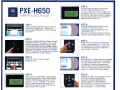
STEP 5:
PXE-H650
5 MINUTE EZ SETUP GUIDE
STEP 1:
Insert included calibration disc, set factory
volume to 3/4, play track 1. Make sure
factory bass/treble/balance/fader controls
are set flat.
STEP 2:
Power up the PXE-H650; the display will read
"ENTER TO SETUP" so press "enter" to start
the Auto Ranging/Auto Summing procedure.
If the display reads something different refer to
pg.15 of the owners manual for Factory Reset
procedure. The display will read "CHECKING
INPUTS"; and after 10-15 seconds the display
will read "ENTER TO START ANTEQ".
STEP 3:
Switch to track 2 on the included
calibration disc.
The PXE-H650's display will now read
"ADJUST XOVER+AMP LEVELS".
Turn all amp Xovers off, then roughly set
amp gains. Use track 3 on the calibration
disc for this. With Alpine amps,1/2 gain for
front/rear and 3/4 gain for sub works fine.
When finished, press enter.
STEP 6:
The PXE-H650's display will now read
"ENTER TO START MULTEQ".
Press enter, now the display will read
"MEASURE POS 1".
Place the microphone where the driver's
head will be, pointing straight up. Exit the
vehicle and close all doors and windows.
STEP 7:
Press the "front" button on the remote
to start measuring position 1. The LED
will change from flashing to steady, and
you will hear the log chirps calibrating
each speaker in the car.
STEP 8:
When position 1 measurement is complete,
the LED will start flashing and the display
will read "MEASURE POS 2". Move the
microphone to where the passenger's
head will be, and close the doors. Press
"front" on the remote to start measuring
position 2, and the LED will go steady.
STEP 4:
STEP 9:
Press "enter" to start AntEQ. This will take
about 20-30 seconds. After AntEQ is done,
the PXE-H650's display will read "2-WAY
OUTPUT, Y or N". Choose "N" if only the
front 2 output is being used; select "Y" if
both front 1 and front 2 outputs are being
used. Press enter to select.
Measure at least 2 more positions in the
car (maximum 8) using the same
procedure. Choose additional mic
positions based on user preference.
After at least 4 mic positions total, press
the "right" button on the remote to
finish calibration. YOU'RE DONE!
PXE-H650 INSTALLATION & USAGE TIPS Output channels configuration:
• Amp gains must be set so that speaker levels (SPL) are matched prior to MultEQ
calibration. This will help assure that one or more channels do not clip the MIC input
during measurements.
• To assist with setting proper amp gains, the AUX input clip LED functions as a MIC
input clip indicator during MultEQ calibration. The clip LED must not illuminate at
any time during the calibration procedure for if it does, the acoustic measurements will
not be accurate.
• The SUB channel is the most likely to clip the MIC input due to high SPL compared
with FRONT and REAR channels. Check to make sure that the SUB level is matched
to the FRONT and REAR speakers and that the clip LED is not illuminating during
calibration.
• Recommended starting amp gain levels prior to MultEQ calibration:
- FRONT and REAR amp gains are set to 1/2 positions (nominal)
- SUBWOOFER amp gain is set to 1/4 position (9 o'clock)
Once MultEQ calibration is completed, final adjustment of amp gains should be carried
out to suit the taste of the system user.
• If MIC input clip LED illuminates at any time during 1st MIC position measurement,
amp levels must reduced and 1st MIC position must be repeated.
MAIN (speaker level) input configuration:
Input channels:
• One pair of full-range stereo inputs (L & R) is all that is needed by the PXE-H650 for
proper operation. If full range stereo inputs are available from the factory system, they
should be connected to the L2IR2 channels of the MAIN (speaker level) input harness.
• If the vehicle has factory crossed over speaker outputs, both high pass (tweeter) and
low pass (midrange) signals must be connected to the MAIN inputs for proper fullrange signal input. The factory subwoofer output may also need to be connected to
achieve a full-range signal.
Polarity:
• All OEM head units that are connected to the MAIN input harness must be wired in
phase, observing correct polarity.
• Reversed polarity on MAIN input channel connections can be detected during the
"ADJUST XOVER+AMP LEVELS" step using Track 3 - Pink Noise prior to MultEQ
calibration. If low or no speaker output is detected on LEFT or RIGHT channels, check
the polarity of the speaker level inputs on that channel.
• After correcting any incorrect wiring polarity, a factory reset should be done and the
PXE-H650 setup procedure should be repeated from the beginning.
Setting OEM head unit volume level
• The OEM head unit volume level must be set so that it is high enough to allow
maximum system output yet low enough to avoid a distorted input level to the PXEH650. 2/3 to 3/4 of maximum volume scale on the OEM head unit is recommended.
Storing custom settings permanently in memory
• After changing any Custom Tuning parameters, you must remember to navigate to
SAVE SETTINGS and press "ENTER" in order to store these settings permanently
in memory.
ffffMLPINER
Mobile Media Solutions
PXE·H650
SYSTEM INTERGRATION AUDIO PROCESSOR
PROCESSEUR AUDIO D'INTEGRATION SYSTEME
OWNER'S MANUAL
MANUEL DU PROPRIETAIRE
IMPRINT
Caution
• Read this manual thoroughly before starting installation and operation. You will find a number of Safety Warnings in this
manual to tell you about things that could hurt you or other people if you were to ignore the Warnings. We cannot be
responsible for problems resulting from failure to observe the Warnings in this manual.
• This manual uses a symbol to show how to use this product safely and to avoid harm to yourself and others and damage
to your property. Here is what this symbol means. Understanding it is important for reading the Manual.
• Meaning of Symbol:
This symbol means there is something that could cause serious injury or
death to ou or other people.
DO NOT DISASSEMBLE OR ALTER
Attempts to disassemble or alter this product can lead to accidental fires or electrical shock.
KEEP SMALL ARTICLES OUT OF THE REACH OF CHILDREN
Keep small articles (wire-ties, etc.) out of reach of children. If swallowed, consult a physician immediately.
USE ONLY IN CARS WITH A 12 VOLT NEGATIVE GROUND
Use only in cars with a 12 volt negative (-) ground electrical system. (Check with your dealer if you are not sure.) Failure to
do so may result in fire, etc.
BEFORE WIRING, DISCONNECT THE CABLE FROM THE NEGATIVE BATTERY TERMINAL
Before doing any electrical wiring, disconnect the cable from the negative (-) terminal of the battery. Failure to do so may
result in electric shock or injury due to electrical shorts.
KEEP ELECTRICAL CABLES TOGETHER TO AVOID OPERATING HAZARDS
Dress the wiring to keep them from interfering with the operation of the steering wheel, gear lever, brake pedals, etc.
DO NOT CUT AWAY INSULATION FROM ANY WIRE TO POWER OTHER EQUIPMENT
Tapping power from wiring to supply voltage to another piece of equipment could exceed the current carrying capacity of
that wire. This could result in fire or electric shock.
DO NOT INSTALL IN LOCATIONS WHICH MIGHT HINDER VEHICLE OPERATION
Do not install in locations which might create hazards for the vehicle occupants or hinder vehicle operation (such as the
steering wheel or gear shift) by obstructing forward vision or hampering movement etc.
DO NOT DAMAGE PIPES OR WIRING WHEN DRILLING HOLES
When drilling holes in the chassis for installation, take precautions so as not to contact, damage or obstruct pipes, tanks or
electrical wiring. Failure to take such precautions may result in fire.
DO NOT USE NUTS OR BOLTS IN THE BRAKE SYSTEM FOR INSTALLATION OR GROUND CONNECTIONS
Never use safety-related parts such as bolts or nuts in the steering or brake systems or tanks to make wiring installations or
ground connections. Using such parts could disable control of the vehicle and cause fire etc.
HALT USE IMMEDIATELY IF A PROBLEM APPEARS
When problems appear, stop using the system immediately and contact the dealer from whom you purchased the
equipment. Some problems which may warrant immediate attention include a lack of sound, noxious odors or smoke being
emitted from the unit, or foreign objects dropped inside the unit.
DO NOT OPERATE THE EQUIPMENT OR LOOK AT THE SCREEN WHILE DRIVING
Do not change settings while driving. If operation requiring a prolonged view of the display is required, stop the vehicle in a
safe location before attempting operation.
HAVE THE WIRING AND INSTALLATION DONE BY EXPERTS
The wiring and installation of this unit requires special technical skill and experience. To ensure safety, always contact the
dealer where you purchased this unit to have the work done.
DO NOT INSTALL IN LOCATIONS WITH HIGH MOISTURE OR DUST
Avoid installing the unit in locations with high incidence of moisture or dust. Moisture or dust that penetrates into this unit
may cause smoke or fire.
MAKE THE CORRECT CONNECTIONS
Failure to make the correct connections can cause fire or accident to occur.
ARRANGE THE WIRING SO IT IS NOT CRIMPED OR PINCHED
Route the cables and wiring so as not to be crimped by moving parts like seat rails or to make contact with sharp spots
which could damage the wiring.
DO NOT RAISE THE VOLUME EXCESSIVELY
Keep the volume at a level where you can still hear outside noises while driving. Driving while unable to hear outside sounds
could cause an accident.
WARNING
Temperature
Be sure the temperature inside the vehicle is between +60 0 e (+140°F) and -10 0 e (+ 14°F) before
turning your unit on.
Fuse Replacement
When replacing the fuse(s), the replacement must be of the same amperage as shown on the fuse
holder. If the fuse(s) blows more than once, carefully check all electrical connections for shorted
circuitry. Also have your vehicle's voltage regulator checked.
Maintenance
If you have problems, do not attempt to repair the unit yourself. Return it to your Alpine dealer or
the nearest Alpine Service Station for servicing.
Installation Location
Make sure the PXE-H650 will not be exposed to:
• Direct sun and heat
• High humidity
• Excessive dust
• Excessive vibrations
Warnings
2
Features/Description
5
SETUP CD - Contents
6
CAUTION - Input Level Adjustment.
6
Remote Control
7
Main Chassis
8
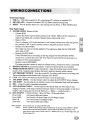
Wiring/Connections
9
Basic Operation
Initial Setup & AntEQ
11
MultEQ
13
Demo Mode
-,
15
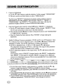
Sound Customization
Equalizer
16
Crossover
17
Time Delay
19
Mounting
20
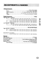
Adjustments and Ranges
21
Specifications
22
The Alpine PXE-H650 is a versatile processor that takes an OK sounding factory system
turns it into a high-end, audiophile system. The PXE-H650 utilizes advanced sound
tuning of the factory equipment to correct the acoustical problems inherent in the vehicle.
Using AntEQTM to remove any factory pre-equalization, Audyssey MultEQTM flattens the
frequency response inside the vehicle's interior and adjusts the overall response to a preselected target curve.
Once sound levels are balanced, and the system is tuned for optimum response, the
addition of Alpine amplifiers and speakers give significant improvement over your factory
hardware. Additional amps for tweeters and subwoofers provide a quality, bi-amped system
extending the system's response far beyond what a normal factory system is capable of. It's
easy to upgrade from factory to Alpine!
£
WARNING
It is dangerous and illegal for the driver to watch VideorrV while driving
any vehicle. The driver may be distracted from looking ahead and an accident could occur.
Features:
•
•
•
•
•
•
•
•
•
•
AntEQ and MultEQ (Imprint technology)
AUX Input (Audio)
5-Channel Factory Head Unit Input (Speaker or Line Level)
6.1 Channel Analog Line Level Outputs (Front 1/2, Rear, Subwoofer)
3 Custom Parametric EQ Bands
Crossover: Front 1/2 HP, Front 2 LP, Rear HP, Sub LP
7-Channel Time Correction
Source-Tone Memory
2 User Presets
IR Remote Control for Source, Sub Level, Muting, Bal/Fad and User Presets
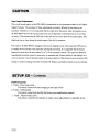
Input Level Adjustment
The overall sound quality of the PXE-H650 is determined by the adjustments made by the Digital
Signal Processor. The accuracy of these adjustments are directly affected by the input to the
processor. Therefore, it is very important that the output from the factory radio be properly set so
the PXE-H650 receives the correct audio level (not so high that it's distorted and not so low that
it's noisy). This ensures that the DSP chip in the unit can see every detail of the audio signal. This
important step is done during the initial stages of the Set Up sequence.
The input to the PXE-H650 is equipped with an auto-ranging circuit. This keeps the DSP input at
a constant level for better noise immunity and signal processing. It is suggested that the factory
head unit volume level be set at about 2/3 to 3/4 of its maximum volume. This position should be
remembered (mark the control in some way or remember the Volume number in the display) so if
it is ever moved, it can be returned easily to the same position. Other functions such as factory EQ
settings or position settings must also be turned off. Balance and Fader positions must be centered.
H650 Setup Disc
1. Track - Auto range setup
This track is used with auto ranging to set input levels
2. Track - AntEQ setup
This track is used with AntEQ for factory pre-equalization removal
3. Track - Adjust Amp Levels
This track is used by the installer to make coarse adjustments to amplifier levels.
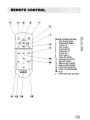
Remote Function Call-outs
1
AUX Source Select
2
Factory H/U Select
3
Volume UP
4
User Preset 1
5
Subwoofer DN
6
Subwoofer UP
7
Volume DN
8
User Preset 2
9
Treble EO UP/DN
10 Midrange EO UP/DN
11 Bass EO UP/DN
12 Balance Left (CLEAR)
13 Balance Right (DONE)
14 Fader Rear (CANCEL)
15 Fader Front (MEASURE)
000
000
&A88
MID
TREB
RIGHT
o
~
C
13
Mute
Center (both BAL and FAD)
------...
I:@.~<Sl
--
~.~
....... • @ ~
,0• • -
-
"-
~
~
--
00
u.
LI
LI
III
III
I
85
-
-
-
...
• ....... OUT .....
....
• ...... ON ......
~
....
o
o
._._-..
_-
.-...---~
•
o
.....
.. AUll .....
• AUX ........... UD
• AUll ..... _ _
"
@
@
@
I
I
._-._._'_1_
'_1• AUll_ ..... J.a
._-
I
' _ _ LID
CJ
·uu_
.....
Front Panel Chassis
1 USB Port - USB cable required for PC control/setup (PC software on supplied CD)
2 MULTEQ LED - Output for included LED; EQ Status indicator during setup
3 RESET - Press & Release button for: Clear settings, Factory Reset, or Redo MultEQ setup
Rear Panel Chassis
4 POWER SUPPLY Harness (6-Pin)
•
5
6
7
8
9
10
11
12
13
Ground (BLK)
Connect this lead to a good chassis ground on the vehicle. Make sure the connection is
made to bare metal and is securely fastened using a sheet metal screw.
• Battery (YEL)
This is a constant +12V for the main unit. It will remain powered even when the Ignition
key position is OFF. It draws minimal current to maintain processor memory.
• Remote OUT (BLU/WHT)
This output can tum on external amplifiers. The signal goes high after the PXE-H650
audio mute is OFF.
• Remote ON (BLU/WHT)
If the OEM head unit is not turning on the EQ using the AUTO RANGING INPUT,
use this wire. Connect this wire to the 'Auto Tum On' lead of the Factory head unit or a
switched 12 VDC source (Ignition).
• Remote Control (WHT/BRN)
This input provides a means by which an external source, connected to AUX, is controlled.
REMOTE IR INPUT (2.5mm mini-phono) - Input for external remote eye (included)
WIRED REMOTE INPUT (3.5mm mini-phono) - Input for steering wheel control (factory
option); Note: Using this input disables the factory head unit steering wheel controls.
AUX PRIMARY SOURCE - Tum this switch ON, if a factory radio source is not being used.
This accommodates an aftermarket radio using the AUX INPUT.
CLIP - This LED is ON whenever the AUX source is over the input limit.
AUX INPUT LEVEL - Use this trimmer control to adjust theAUX INPUT below clipping.
AUX INPUT - Use this input for an auxiliary source or an aftermarket head with line outputs.
MIC - 3.5mm TIS jack for included microphone
AUTO RANGING INPUT - Use this input for the factory head unit. This input is 'auto
ranging' to handle a wide range of factory head unit outputs. It will accept speaker or line level
outputs. It has 5 input pairs for Front & Rear Left +1-, Right +1-, and Subwoofer +1-.
RCA OUTPUT - 2 Front L/R Pairs, 1 Rear L/R Pair, 1 Subwoofer Mono
Front Ll/RI
For Factory High-pass Output
Front L2/R2
For Factory Low-pass Output (or Full Range Output)
Rear L/R
For Factory Rear, Full Range Output
Subwoofer
For Factory Subwoofer Output
Note: OUTPUT:
INPUT:
For full-range only, use outputs FRONT l21R2
If there is a UR pair of full range outputs available from the factory system (FRONT or REAR)
these should be used first and connected to inputs L21R2 on the H650. If the factory 2-way
output must be used, connect Tweeter Left to Ll, Woofer Left to L2, Tweeter Right to RI, and
Woofer Right to R2.
Before Running AntEQ
The following guidelines will ensure a smooth and accurate setup procedure. Have the
MultEQ CD, microphone and LED available and take a note of the conditions below
as they are needed in the next section. Some type of stand is also needed to place the
microphone at different locations in the vehicle. A clip or tape is not always a good
idea as not everyone's ear can be stuck to the headliner or clipped to the visor. The best
locations are where a head is most likely to be found (along with its accompanying
body).
1. Determine the factory system's output type (full-range or two-way). If you know
that your vehicle has tweeters mounted in the dash or door panels, the Factory Radio
probably has two-way outputs.
In the case of a two-way system, make sure the tweeter output goes to the Ll/R1
inputs and the low output goes to the L2/R2 inputs. At this time, decide the crossover
point for the high-pass speakers. Find the low cut-off point of the tweeters and
use that as the HP cut-off (5 kHz by default). The mid-bass low-pass cut-off is
determined by tweeter high-pass. If there is a subwoofer in the system, the low pass
cut-off will be set automatically by MultEQ.
If the output is full range, the factory radio output must go to the L2/R2 inputs.
2. It is recommended to start MultEQ calibration with the 1st MIC position in the
driver's seat and the 2nd MIC position in either the passenger's seat or in between the
two front seats. Just remember, the more positions that are included in the calibration,
the better the results will sound. MultEQ requires a minimum of 4 MIC positions and
has a limit of 8. The number and location of the MIC positions is left up to the user.
However, following the guidelines described here have been found to give the best
results.
3. PRESET 1 settings are derived from MIC position 1 and PRESET 2 settings are
derived from MIC position 2. The 3rd through 6th MIC positions should be grouped
where the driver's head would be positioned. The 7th and 8th MIC positions should
be in the rear seats.
NOTES:
• It is possible that poor MIC positioning could cause anomalies in the calculated
response curve. If this happens during the first calibration run, try moving the MIC
positions 3 through 8 to more favorable positions.
• If using the AUX Input as the primary source for the EQ, the REMOTE ON wire
must be used. Otherwise, there is no way for the EQ to turn on. Use the Remote On
wire from the head unit or a source of switched ACC voltage (Ignition).
Initial Setup & AntEQ
Initially, a blank display is shown during sleep mode (before head unit powers up).
1.
TURN ON Vehicle Ignition Switch
2.
TURN ON Factory Radio Power and insert the H650 Setup CD.
If properly connected, the Factory Radio Power should automatically turn ON the
PXE-H650. The PXE-H650 display = "ALPINE PXE-H650" if already setup.
If this is the very first time the PXE-H650 is being used, the system will enter the
SETUP mode automatically. When it does so, follow the steps below. If you don't
enter the setup mode automatically please refer to page 15 and FACTORY RESET.
3.
Adjust Factory Head Unit.
Head unit controls such as TONE, EQ or other special processing must be turned
OFF. Set BALANCE and FADER controls to their center position. Make sure that the
volume control on the factory head unit is set at about 2/3 to 3/4 of its maximum output.
This will ensure that any automatic frequency compensation circuitry in the head
unit is off. It also ensures that the output is not distorted but at a high enough level to
provide a good signal for accurate processing to take place.
The PXE-H650 utilizes an auto-ranging circuit for the Factory Head Unit input. This
enables considerable flexibility in making output adjustments of the factory head unit.
Once the level is set, the factory volume control (and others) should not be changed.
Volume will be controlled through the PXE-H650 using the supplied remote control.
Play Track 1, "Autorange Setup," of the Setup CD loaded in Step 2 above.
4.
"ENTER TO SETUP"
This is displayed when the PXE-H650 is Powered UP for the first time (or after a
'FACTORY RESET' is performed). Press "ENTER" to initiate SETUP sequence.
SETUP continues with Auto Ranging level setting ("CHECKING INPUTS").
5.
"CHECKING INPUTS" - Checking and setting input levels from the head unit
Before AntEQ begins analyzing the factory radio's output, proper signal levels are
required. The Auto-ranging process is completed when "ENTER TO START ANTEQ"
is displayed.
Play Track 2, "AntEQ Setup", of the Setup CD loaded in Step 2 above.
6.
"ENTER TO START ANTEQ" - Continue with AntEQ processing
Press ENTER to continue to the AntEQ procedure. Whatever levels were set during
auto-ranging are now used as the baseline response for AntEQ.
7.
"AntEQ SAVING" - AntEQ completes and saves the resulting filters.
AntEQ has flattened out any equalization that is inherent in the factory radio. This is
in preparation for the MultEQ process in the upcoming steps. After completing this
process, the settings are saved and recalled when required for new settings.
2-Way Output Settings
8.
"2-WAY OUTPUT" - Following "AntEQ SAVING"
If the FRONT Output is configured as a 2-Way system, select 'Y' at the prompt and
press "ENTER." The default 'N' assumes only a single, full range Front (Front L2/R2).
If 'Y' is selected, the crossover is set in Step 9 below.
If 'N' is selected, skip to the AMP LEVELS adjustments. FRONT 1 is turned OFF and
FRONT 2 is set as a Full Bandwidth output.
WARNING: Output of the PXE-H650 is not muted at this point. Make sure volume
levels are at reasonable levels.
9.
"FRONT 1 HPF" - Set the High-pass crossover point
The FRONT 1 high-pass crossover is set to 5 kHz by default. This also selects the
FRONT 2 Low-pass crossover at the same point.
Use the Tor. button to change the value in the HPF field. Values available for each
crossover are listed in the "ADJUSTMENTS & RANGES" section.
Press "ENTER" to continue.
WARNING: Output of the PXE-H650 is not muted at this point. Make sure volume
levels are at reasonable levels.
Amplifier Levels
10. "ADJUST XOVER + AMP LEVELS" - Make adjustments to match amp levels
Play Track 3 of the PXE-H650 Setup Disc in the Factory Head unit. This is a Pink
Noise signal to facilitate the trimming of the amplifier level controls.
WARNING: Output of the PXE-H650 is not muted at this point. Make sure volume
levels are at reasonable levels.
While listening to the system, use the amp's level controls to match the output of each
of the speakers. Level matching does not have to be exact as the MultEQ processing
will make the final tweaks to the system. Matching levels as closely as possible makes
MultEQ's job a little easier and faster. Typical coarse amp levels are:
12 o'clock (middle position on gain controls) for Front and Rear amp input levels,
9 o'clock (or 1/4 position) for Subwoofer amp input level.
11. After all adjustments have been made, press "ENTER" to continue to MultEQ
calibration.
MultEQ Calibration
At this point in the process, a baseline response curve has been created and stored for
your specific vehicle. This curve ensures that the MultEQ algorithms are working with
a reasonably neutral sounding curve. This eliminates all the peaks and dips in the source
unit, making MultEQs job much easier.
1.
"ENTER TO START MULTEQ" - Prepare vehicle for calibration
Make sure the MultEQ LED and microphone are connected (TIP: LED is OFF if
no mic connected). The MultEQ LED is Green and blinks at 1Hz when LED and
Microphone are properly connected.
The microphone should be placed in the primary listening position (normally the
driver's seat). This position is saved as PRESET 1 and is used as the reference for
all further DSP calculations. Plan to use at least 6 different positions for optimum
performance (minimum is 4 and maximum is 8 positions)
Press "ENTER" to start the MultEQ calibration procedure. The MultEQ LED blinks
slowly (1 Hz) during normal operation.
2.
"CONNECT LED & MIC"
If the PXE-H650 does not detect the microphone, "CONNECT LED & MIC" is
displayed and the MultEQ LED blinks quickly. Troubleshoot the microphone to ensure
proper operation and connection. The system will continue automatically when the
microphone is detected.
3.
"MEASURE POS I" - Prepare to run the calibration test
If the Mic checks out in Step 2 above, the MultEQ LED is blinking slowly.
Position the Mic in location 1 and exit the vehicle. Close all windows.
Press MEASURE on the remote control to begin (see Page 7).
4.
"CHK OUTPUTS & MIC" - Speaker detection Error
If there was a problem during the Speaker Detection process, the PXE-H650 displays
the above error display on the LCD and the LED will blink quickly. Troubleshoot the
system by making sure that nothing has become disconnected or turned off.
Press the reset button after correcting any problems. Navigate to "RECALIBRATE
MULTEQ" in the display. Press "DONE" on the remote control to finalize MultEQ
filter calibration or "MEASURE" to the next mic position of calibration. The LED
blinks slowly between position measurements.
5.
"MEASURE POS 2"
Reposition the microphone to the secondary position in the vehicle. When ready, exit
the vehicle and press "MEASURE" on the remote control to begin. The MultEQ LED
illuminates a steady green. .
6.
"CHK OUTPUTS & MIC"
If the MultEQ LED is blinking fast, something may have happened to the mic during
the user's exit. Make any necessary corrections to position, etc. It will then be
necessary to restart the calibration sequence. At this point, press the reset button and
navigate to the "RECALIBRATE MULTEQ" option screen. Press "ENTER" to select
this option. The "2-WAY OUTPUT" screen is displayed. Configure this setting the
same as previous MultEQ sequence. Press "ENTER" and re-check amp and crossover
levels with Track 3 -Pink Noise. Press "ENTER" when ready to restart the MultEQ
calibration sequence. Resume the first MIC position measurement (and speaker
detection) by jumping back to step 3 when ready.
7.
Next MIC Position
At the "MEASURE pas 3" display, reposition the microphone to another position.
Repeat Step 5 above for this new position.
Continue this process for up to 5 more microphone positions. 4 calibrated positions is
the minimum for proper MultEQ response. 6 positions is recommended for optimal
results. Normally, the more locations used, the more accurate the final EQ curve.
NOTE:
Mic Position 1 is stored in PRESET 1. Mic Position 2 is stored in PRESET 2.
Equalization and Time Delay will be optimized for these two positions.
8.
Done
After completing the desired number of MIC positions, press "DONE" while
"MEASURE pas X" (Where X is either 5,6,or 7) is showing on the display. When
calibration is completed in the last step, "CALCULATING FILTERS" then "SAVING
FILTERS" is displayed on the LCD and finally "ALPINE PXE-H650" is displayed.
NOTE:
Press the "RESET" button on the main chassis, any time during the calibration process, to
return to the Main Menu. From the Main Menu, four options are available.
• RECALIBRATE MULTEQ: Press ENTER at this display to clear the previous MultEQ
settings. The current levels and AntEQ settings are not changed.
• CLEAR SETTINGS: Press ENTER at this display to clear all Customization settings.
This returns the processor to the last MultEQ baseline response.
• FACTORY RESET: Press ENTER at this display to return the PXE-H650 to its original
factory condition. The entire calibration procedure must be redone.
• CANCEL: Press ENTER at this display to return to PXE-H650 STANDBY mode.
Demo Mode Overview
• Demo mode will allow the user to audition MultEQ/AntEQ ON and OFF with the press
of a single button on the remote control.
Demo Mode
• Press the MODE button once on the PXE-H650 to reach the Demo mode screen on the
LCD. Press the "ENTER" button once to enter the Demo mode. At this time, "DEMO
MODE ON" appears in the display. Press the Fader "REAR" button to tum OFF MultEQ/
AntEQ, while pressing the Fader "FRONT" button turns MultEQ/AntEQ ON.
• While in the Demo mode, all remote controller buttons are locked out except: Volume
UP, Volume DOWN, HU andAUX source switch buttons, and MUTE (if AUX
PRIMARY SOURCE switch is ON then HU source switch button is also locked out).
• Press the "ENTER" button again to tum off the Demo mode and resume normal
operation. At this time, "DEMO MODE OFF" appears in the display.
Introduction
Each output of the PXE-H650 has a 3-Band, parametric equalizer, up to 10 ms of time
correction and customizable crossover points for High-pass, Low-pass and Subwoofer.
Experimentation with the sound is encouraged, as a simple press of the RESET button and
selecting "CLEAR SETTINGS" will return all settings back to their original, corrected
levels before customization began.
The following procedure explains the steps necessary to customize the Parametric EQ,
Time Delay and Crossover. Use the same procedure described below, for each of the
channels being modified. Pressing "ENTER" gets you into the program screen mode,
which will allow current values to then be changed. Navigate to "SAVE SETTINGS"
screen and press ENTER to store changes in memory.
Parametric Equalizer
The Equalizer uses 3 Bands for each of the 7 channels to customize the tone of the music.
Each Source Input to the PXE-H650 has its own EQ. Each of the Bands (Bass, Mid and
Treble) is adjusted in a similar manner. The following steps use the Bass Band as an
example. Use the same steps to make changes to the Mid and Treble Bands as well.
Equalizer
1.
Press MODE to enter Custom Tuning mode.
2.
With "PRESET 1" in the display, use the 'Y or A buttons to choose the MIC position
to modify or to choose the EQ Adjustment mode. (PRESET 1 or PRESET 2)
a) PRESET 1 refers to the Primary Mic position. PRESET 2 refers to the Second mic
position.
b) Upon making the Mic Position selection, use the. button to move to the next
selection mode. The next parameter to modify (Crossover, or Time Delay) is
selected as described following EQ Adjustment.
* Use the ~ button to return to the PRESET selection mode.
3.
EQ Adjustment
a) Use the 'Y or A buttons to select "CUSTOMAUX EQ" or "CUSTOM HU EQ."
b) The user can also use these buttons to select "CROSSOVER" or "TIME DELAY"
when in the PRESET 1 or PRESET 2 menus (in 2b above).
The following BASS adjustment procedures are similar in nature to the MID and
TREBLE adjustments. Substitute "MID" or "TREB" for "BASS" and perform the
same procedure mentioned below for "BASS."
4.
5.
Select the EQ Band to adjust.
a) Use the Tor .. button to make the selection. In this example, "BASS" (or "MID"
or "TREB").
b) Once the Band has been selected, Press "ENTER" to begin making the adjustments.
Modify 3 different EQ parameters: LEVEL, Q, and Fc. Use the ~ or ~ buttons to
choose the parameter to modify. Use the Tor .. buttons to change the parameter.
a) LEVEL is adjustable from -6 dB to +6 dB using the T or .. buttons.
This adjustment will effectively lower by 25% or increase by 400%, the output at
the center frequency. The LEVEL changes in 1 dB steps.
b) Q (Q-factor) is adjustable from 0.5 (wide band) to 2.0 (narrow band).
The Q determines how much the frequencies below and above the center frequency i
are affected by the LEVEL adjustment in 'a.' Use the Tor .. buttons to choose a
Q-factor from 0.5 to 2.0 in steps of 0.5.
c) Fc (center Frequency) is adjustable from 30 to 150 Hz.
This is the point of maximum effect for the EQ LEVEL adjustment. All frequencies
above and below Fc are affected to a lesser degree, depending on the Q setting. The
frequencies are selectable using the T or .. buttons. They vary for each band and
are listed below.
BASS EQ: Fc = 30,40,5060,80, 100, 125, 150 (Hz)
MID EQ:
Fc = 500, 750, 1k, 1.5k, 2k, 3k, 4k, 5k (Hz)
TREB EQ: Fc = 6k, 7.5k, 10k, 12.5k, 15k, 17.5k (Hz)
d) Upon completing the adjustment, press ENTER to save values and exit back to the
"CUSTOM EQ" HU or AUX sub-menu headings of BASS, MID or TREB EQ.
e) Use the MODE button at any point, to return to the previous sub-menu.
Crossover Overview
The PXE-H650 crossover allows custom cut-off points for the high-pass and low-pass
filters of the Front and Rear speakers and the Subwoofer. This is especially useful when the
factory speakers have been upgraded to handle a much wider audio bandwidth.
Crossover
1.
2.
Press MODE twice to enter Custom Tuning mode.
Navigate to the right with the right cursor button. With "PRESEf 1" in the display, use
the Tor .. buttons to choose the MIC position to modify.
a) PRESET 1 refers to the Primary Mic position. PRESET 2 refers to the Secondary
position.
b) Upon making the Mic Position selection, use the ~ button to move to the next
selection mode. The next parameter to modify (Crossover, or Time Delay) is
selected as described below.
* Use the ~ button to return to the PRESET selection mode.
3.
Crossover Adjustment
a) Use the ~ or. button to make the selection. In this example, "CROSSOVER"
b) The user can also use these buttons to select "TIME DELAY."
The following "FRONT 2" adjustment procedures will be similar in nature to
adjustments for the other channels. Just substitute "FRONT 1," "REAR," or
"SUBWOOFER," for "FRONT 2." The procedure is the same with only the
parameters slightly different, as shown at the end of this section.
4.
Enter the Channel select mode by using the ~ button. "FRONT 1" is displayed.
a) Use the ~ or. button to choose a channel. In this example, "FRONT 2." Note:
Use the same procedure to select any of the other channels.
b) User can also use the ~button to return to the previous level with "CROSSOVER"
or "TIME DELAY" selections.
c) Once the channel has been selected, Press "ENTER" to begin making the
adjustment.
5.
Modify 2 different Crossover parameters: LEVEL and Fc (cut-off Frequency). Once
Fc is selected, the Crossover becomes active. Use the ~ or ~ buttons to choose the
parameter to modify. Use the ~ or. buttons to change the parameter.
a) LEVEL is adjustable from -15 dB to + 15 dB using the ~ or • buttons.
This adjustment changes the LEVEL in 1 dB steps. The range for this parameter
remains the same for ALL Channels in ALL modes.
b) The Fc adjustment depends on the output mode. The ~ or. buttons select the
frequency.
The frequency range of FRONT 2 changes based on the FRONT 1 configuration.
Once FRONT 1 is activated (Fc selected), FRONT 2 changes from a High-pass
crossover to a Band-pass crossover. This is to accommodate the 2-way output mode.
The Fc changes as follows:
Output Mode
2 or 4 CH, wlwo Su~
FRONT 1
FRONT 2
REAR
SUB
NA
HPF: 50 - 200 Hz @-12dB/oct
HPF: 50 - 200 Hz @ -12 dB/oct
LPF: 50 - 200 Hz; -12/-24 dB/oct
LPF: 200 - 5k Hz @ -12 dB/oct;
HPF: 50 - 200 Hz@-12dB/oct
HPF: 50 - 200 Hz@ -12 dB/oct
LPF: 50 - 200 Hz; -12/-24 dB/oct
2-Wrt. 4-CH, ~H; wlwo Su~ HPF: 200 - 5 kHz@-12dB/oct
c) For the Subwoofer Channel, a third parameter is available. Use the the ~ or •
buttons to toggle between the 12 dB/oct or 24 dB/oct crossover slopes.
d) Upon completing the adjustment, press ENTER to exit back to the "CROSSOVER"
sub-menu.
e) If all CROSSOVER adjustments have been completed, use the ~ button to return to
the PRESET selection mode. Press ENTER again to exit and save the adjustments.
f) Use the MODE button at any point, to return to the previous sub-menu to make
additional adjustments. "SAVE SETTINGS" stores changes in memory.
Time Delay Overview
MultEQ determines the default delay during initial Setup. However, there may be times
when the delay needs to be tweaked or temporarily modified. Be advised, any changes
made causes deviation from MultEQ's default specs and no longer conforms to its ideal
sound stage. All channels have delays adjustable from 0 to 10ms in 0.1 ms steps.
Time Delay
1.
Press MODE twice to enter Custom Tuning mode.
2.
With "PRESET 1" in the display, use the" or • buttons to choose the MIC position
to modify.
a) PRESET 1 refers to the Primary Mic position. PRESET 2 refers to the Second mic
position.
b) Upon making the Mic Position selection, use the ~ button to move to the next
selection mode. The next parameter to modify (Crossover, or Time Delay) is
selected as described below.
* Use the ~ button to return to the PRESET selection mode.
c) Use the" or. buttons to choose TIME DELAY.
d) Press the ~ button to move to the Channel selection mode.
e) Use the" or. buttons to select a Channel to modify (FRONT LEFf l/RIGHT
1, FRONT LEFf 2/RIGHT 2, REAR LEFf,RIGHT, SUBWOOFER). Use the ~
button to return to the PRESET selection mode.
3.
Time Correction
a) With the desired channel selected, press ENTER, to begin the adjustment.
b) Use the" or. buttons to change the delay (from 0 to 10ms) for each channel.
c) Upon completing the adjustment, press ENTER to exit back to the "TIME DELAY"
sub-menu.
d) If all "TIME DELAY" adjustments have been completed, use the ~ button to
return to the PRESET selection mode. Press ENTER again to exit and save the
adjustments. Selecting "SAVE SETTINGS" stores changes in memory.
e) Use the MODE button at any point, to return to the previous sub-menu. to make
additional adjustments.
NOTES:
• Customization alters the MultEQ post-calibration settings. Doing this mayor may not
result in an improvement of the overall sound quality.
• If setup includes a 2-Way output, the FRONT 1 High-pass and FRONT 2 Low-pass
cut-off frequencies should not be altered during customization. If these crossover
points must be changed, the MultEQ calibration must also be rerun.
E
E
0"1
---------v-------...-l
...-l
-4-T-~-------------------------_+i.t__
00
000
o
E
E
1.0
......
M
N
3 Band Parametric
Q
Level
Bass Frequency
Mid
Treble
Digital Crossovers
High Pass (@ -12 dB/oct)
0.5 to 2 (0.5 steps)
-6 to +6 dB (1 dB steps)
Fe = 30, 40, 50, 60, 80, 100, 125, 150 Hz
Fe
= 0.5, 0.75, 1.0, 1.5, 2.0, 3.0, 4.0, 5.0 kHz
Fe = 6, 7.5, 10, 12.5, 15, 17.5 kHz
2-Way
F1
200, 220, 250, 280, 315, 360, 400, 450, 500, 560, 630, 710, 800, 900, 1k
.......................... 1.2k, 1.4k, 1.6k, 1.8k, 2k, 2.2k, 2.5k, 2.8k, 3.2k, 3.6k, 4k, 4.5k, 5k Hz
F2
50, 60, 70, 80, 90, 100, 110, 120, 130, 140, 150, 160, 170, 180, 190, 200 Hz
R
50, 60, 70, 80, 90, 100, 110, 120, 130, 140, 150, 160, 170, 180, 190, 200 Hz
Low Pass (@ -12 dB/oct)
F2
200, 220, 250, 280, 315, 360, 400, 450, 500, 560, 630, 710, 800, 900, 1k
.......................... 1.2k, 1.4k, 1.6k, 1.8k, 2k, 2.2k, 2.5k, 2.8k, 3.2k, 3.6k, 4k, 4.5k, 5k Hz
...............................................................................Normal (Full Range)
High Pass (@ -12 dB/oct)
F2
R
50, 60, 70, 80, 90, 100, 110, 120, 130, 140, 150, 160, 170, 180, 190, 200 Hz
50, 60, 70, 80, 90, 100, 110, 120, 130, 140, 150, 160, 170, 180, 190, 200 Hz
Subwoofer (@ -12/-24 dB/oct)
........................... 50, 60, 70, 80, 90, 100, 110, 120, 130, 140, 150, 160, 170, 180, 190, 200 Hz
General
User Memory
PC Control Interface
Pre-amp Control
Source Select
Remote Turn-on
Turn-off Delay
2 Presets
USB
Volume/Balance/Fader/Sub Level
HU (Factory)/AUX
Automatic Input Signal Sensing
5 minutes
MAIN UNIT MAIN Input
AUX Input
SPECIFICATION
VALUE
Max Input Level
16 Vrms
Max Input Level
1.5 Vrms
(AUX PRIMARY OFF)
Max Input Level
2.5 Vrms
(AUX PRIMARY ON)
GENERAL
Output Impedance
<1kn
Frequency Response
20 Hz to 20 kHz
THD
<0.2%
SNR
82 dB
Power Requirement
12.0 VDC
(11-16 VDC allowable)
Operating Current
< 700 mA
Operating Temperature
+14°F to +140°F
-10°C to +60°C)
Dimensions
252mm x 38mm x 149mm
Weight
1.0kg/35.3 oz
Accessories
RUE-4265 Remote Control..
Power Supply Connector
x1
x1
Speaker Input Connector
Microphone
IR Remote Sensor
MultEQ LED
Batteries (AAA)
Owner's Manual.
Imprint Setup CD
x1
x1
x1
x1
x2
x1
x1
NOTES:
Due to continuous product improvements, specifications and design are subject to change without notice.
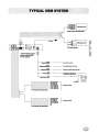
I Front LIft lW~
I Front LIft WP
I
I
8
..
r~~~ ~O_:_M_:_ofer
__
r-------------------------! l1 :J
f-------------------------!1.11
~
f-----------------------~All
IRs..-
:Y=is
Full Range Syatem
• AUX Primary Source
switch must be OFF
for this system
---
__
In_~
_ONc-.
_CUTc-.
L
_
~-------------------------
r-----~--------------
r-------------------------r-------------r--------------------------
G~"'a_part'"
IJ cMNIa bodJ wllIla _ .
lIuIIwocn' 0Ulpul
,.., 0Ulpul (L)
,.., 0Ulpul (RI
Front 2 0Ulpul (LI
"""" 2 Output (R)
Franl1 Output (L)
_1 Output (R)
}---
Iubwoofer 0Ulpul
}---
e CH System wtth Subwoofer
I
--L-~;~=~~:ulL-_-_-_-_-_-_-_-_-_-_-_-_-_-_
~-------------------------
-0ulpuI(L)
_OulpuI(R)
Output (L)
Output (R)
NC
NC
-------------- '-- z
r------------------------- '-- z
r--------------
r----------------------4 CH System with Subwoofer
u_n_lt_
_. _.
" - - ON Cable -
--
-=-
:~~~@l.:@
T TT
@N Q
-o-0'!"
...... -.
-
- 1I:IIl........ OUT c.bIe
-
IR8eneor -
--.
00
...:.::.u
8B
---
" - - Q>nIIaI c:.IIle
iii
""'"'" OUT c:.IIle
QI'OlIIld C'"
-
I
a-y " - c:.IIle
I
I
II
I
•I
I
I
I
I II
•
I•,
i------------------~~~
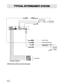
-----------------------8uIrMIoIIIr
~0utpuI(R)
•L - - - - - - - - - - - - - - - - - - - !tOft:l
ftOft:lOulpul(Ll
0uIpul (RI
--------------------·!tOft10u1pul(Ll
1 0uIpul (R)
~----------------------------ftOft
I CH SylItIm with 8ubwooflIr
* AUX Prime" Source switch must be ON for this system
----
Not uMd In "'.. .,....
---- - - - -
'Ill Ell...... AlpIne " - - ON c:.IIle
-----
NOTES
LIMITED WARRANTY
ALPINE ELECTRONICS OF AMERICA, INC. AND ALPINE OF CANADA INC. rAlplne'), are dedicated to quality craftsmanship and are
pleased to offer this Warranty. We suggest that you read It thoroughly. Should you have any questions, please contact your Dealer
or contact Alpine at one of the telephone numbers listed below.
ePRODUCTS COVERED:
This Warranty covers Car Audio, Navigation Products and
Related Accessories ('the producf). Products purchased in the
canada are covered only In the canada. Products purchased in
the U.S.A. are covered only in the U.S.A.
.LENGTH OF WARRANTY:
This Warranty Is in effect for one year from the date of the first
consumer purchase.
.WHO IS COVERED:
This Warranty only covers the original purchaser of the product,
2 You should provide a detailed description of the problem(s) for
which service Is required.
3 You must supply proof of your purchase of the product.
4 You must package the product securely to avoid damage durIng shipment. To prevent lost packages it Is recommended to
use a carrier that provides a tracking service.
.HOW WE LIMIT IMPLIED WARRANnE8:
ANY IMPLIED WARRANTIES INCLUDING FITNESS FOR USE
AND MERCHANTABILITY ARE LIMITED IN DURATION TO THE
PERIOD OF THE EXPRESS WARRANTY SET FORTH ABOVE AND
NO PERSON IS AUTHORIZED TO ASSUME FOR ALPINE ANY
who must reside in the United States, Puerto Rico or Canada.
OTHER LIABILITY IN CONNECTION WITH THE SALE OF THE
.WHAT IS COVERED:
PRODUCT.
This Warranty covers defects In materials or workmanship (parts .HOW WE EXCLUDE CERTAIN DAMAGES:
and labor) In the product.
ALPINE EXPRESSLY DISCLAIMS LIABILITY FOR INCIDENTAL
.WHAT IS NOT COVERED:
AND CONSEQUENTIAL DAMAGES CAUSED BY THE PRODUCT.
This Warranty does not cover the following:
THE TERM 'INCIDENTAL DAMAGES' REFERS TO EXPENSES OF
1 Damage occurring during shipment of the product to Alpine
TRANSPORTING THE PRODUCT TO THE ALPINE SERVICE CEN·
for repair (claims must be presented to the carrier).
TER, LOSS OF THE ORIGINAL PURCHASER'S TIME, LOSS OF
2 Damage caused by accident or abuse, including burned voice THE USE OF THE PRODUCT, BUS FARES, CAR RENTALS OR
colis caused by over-driving the speaker (amplifier level Is
OTHERS COSTS RELATING TO THE CARE AND CUSTODY OF
turned up and driven into distortion or clipping).
THE PRODUCT. THE TERM 'CONSEQUENTIAL DAMAGES'
Speaker mechanical failure (e.g. punctures, tears or rips).
REFERS TO THE COST OF REPAIRING OR REPLACING OTHER
Cracked or damaged LCD panels. Dropped or damaged hard
PROPERTY WHICH IS DAMAGED WHEN THIS PRODUCT DOES
drives.
NOT WORK PROPERLY.
3 Damage caused by negligence, misuse, Improper operation or THE REMEDIES PROVIDED UNDER THIS WARRANTY ARE
failure to foliow Instructions contained In the Owner's manual. EXCLUSIVE AND IN LIEU OF ALL OTHERS.
4 Damage caused by act of God, including without limitation,
.HOW STATE/PROVINCIAL LAW RELATES TO THE WARRANTY'
earthquake, fire, flood, storms or other acts of nature.
'
Any cost or expense related to the removal or reinstallation of This Warran~ gives ¥ou specific legal rights, and you may also
the product.
have. other nght~ :"hlch vary from state. to state and province to
5 service performed by an unauthorized person company or
~roVlnce. In addition, some states/provinces do not allow Iimita·
association.
' t l o n s on how long an Implied warranty lasts, and some do not
6 Any prodUct which has the serial number defaced altered or allow the exclusion or limitation of Incidental or consequent!al
removed.
'dam~ges. Accordingly, limitations as to these matters contained
7 Any product which has been adjusted, altered or modified
herein may not apply to you.
without Alpine's consent.
.IN CANADA ONLY:
8 Any product not distributed by Alpine within the United States, This Warranty is not valid unless your Alpine car audio product
Puerto Rico or Canada.
has been Installed In your vehicle by an Authorized Installation
9 Any product not purchased from an Authorized Alpine Dealer. Center, and this warranty stamped upon Installation by the
.HOW TO OBTAIN WARRANTY SERVICE:
installation center.
1 You are responsible for delivery of the product to an
.HOW TO CONTACT CUSTOMER SERVICE:
Authorized Alpine Service Center or Alpine for repair and for
Should the product require service, please call the following
payment of any initial shipping charges. Alpine will, at its
number for your nearest Authorized Alpine Service Center.
option, repair or replace the product with a new or reconditioned product without charge. If the repairs are covered by
CAR AUDIO 1·800-ALPINE·1 (1-800·257-4831)
the warranty, and if the product was shipped to an Authorized
Alpine service Center or Alpine. Alpine will pay the return ship- Or visit our website at; http://www.alplne-usa.com
ping charges.
ALPINE ELECTRONICS OF AMERICA, INC.,
19145 Gramercy Place, Torrance, California 90501, U.S.A.
ALPINE ELECTRONICS OF CANADA, INC.,
777 Supertest Road, Toronto, Ontario M3J 2M9, Canada Phone 1-416-736-6211
Do not send products to these addresses.
Call the toll free telephone number or visit the website to locate a service center.
C 2006 Alpine Electronics of America, Inc. All Rights Reserved.
ALPINE ELECTRONICS, INC.
Tokyo office; 1-1-8 Nishi Gotanda,
Shinagawa-ku, Tokyo 141-8501, Japan
Tel.: (03) 3494-1101
ALPINE ELECTRONICS OF AMERICA, INC.
19145 Gramercy Place, Torrance,
California 90501, U.S.A.
Tel.: 1-800-ALPINE1 (1-800-257-4631)
1-888-NAV-HELP (1-888-628-4357)
ALPINE ELECTRONICS OF CANADA, INC.
Suite 203, 7300 Warden Ave. Markham, Ontario
L3R 9Z6, Canada
Tel.: 1-800-ALPINE1 (1-800-257-4631)
ALPINE ELECTRONICS OF AUSTRALIA PTY. LTD.
6·8 Fiveways Boulevarde Keysborough Victoria 3173,
Australia
Tel.: (03) 9769-0000
ALPINE ELECTRONICS GmbH
Kreuzerkamp 7-11 40878 Ratingen, Germany
Tel.: 02102-45 50
ALPINE ITALIA S.p.A.
Via C.Colombo 8, 20090 Trezzano
SuI Naviglio MI, Italy
Tel.: 02-48 47 81
ALPINE ELECTRONICS FRANCE S.A.R.L.
98, Rue De La Belle Etoile, Z.1. Paris Nord \I B.P.50016
F-95945, Roissy, Charles De Gaulle Cedex, France
Tel.: 01-48 63 89 89
ALPINE ELECTRONICS OF U.K., LTD.
13 Tanners Drive, Blakelands,
Milton keynes MK14 5BU, U.K.
Tel.: 01908-61 1556
ALPINE ELECTRONICS DE ESPANA, S.A.
Portal De Gamarra 36, Paboll6n 32
01013 Vitoria(Alava)-Apdo. 133, Spain
Tel.: 34-45-283588
Printed in U.S.A.
.#AY/iLPINE.
Mobil,
Mect~
SokIlkoftl
PXE-H650 SETUP DISC
V2.2.7
rl\UDYSSEY
...... '(0
xr
~/iLPINE.
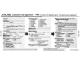
Customer Care Registration
......... For easy on-line registration, go to ..www.alpine-usa.com/registration..
Thank you for choosing Alpine! Please register your product with us so we can serve you better.
First name:
----,.
Last name: _ _
~
_
• Product purchased
_
1,0 Cassette Player
2. 0 CD Player
3. 0 MD Player
4. 0 DVD Player
5. 0 CD Changer
6. 0 Amplifier
7.0 Speaker
8. 0 Subwoofer
Home address: "'Street="'"'add="""''==-----------
City
ZiP COde
SlatelProv
May we' contact you at this address? 1.0Yes 2.0 No
Phone number: (
)
----------::=-----=~
May we contact you at this number? 1. 0 Yes 2.0 No
w
a:
w
E-mail Address:
May we contact you by e-mail?
:I:
..J
<C
w
(JJ
....,-_--:.-_-----;:,,----=,,-----
• Gender
1.0 Male
1. 0 Yes 2.0 No
2.0 Female
• Date of Birth Month:
Year:
~--• Marital Status
1.0 Single
2. 0 Married
• Which ethnlclty best describes yourself:
1. 0 Caucasian
2. 0 Hispanic
3. 0 African-American
4. 0 Asian
5.0 Other
-+
o
High SChool Student
High School Graduate
2 Yr. DegreelSome College
Completed 4 Yr. College
Completed Graduate SChool
1.0Yes.j,
'
_
_
• Date of Purchase:
Year:
navigation system, which monitor?
1.0 Alpine ~ (Model No.)
_
2.0 Other ~ (Brand Name)
----------
• Purpose of buying this unit?
_
o
1.
Addition
2.0 Replacement ~
*Previous brand replaced?
1.0 Factory installed
2.0 Alpine
3.0 Other
-+
.
Occupation
1. ~ ExecutivelManagerial
Thank you for your cooperation! We value your privacy. This information will remain confidential with Alpine and its affiliates.
2.
o Two or more times
6.
7.
2.
SecretariaVClerical
3.
Sales
'4.
General Labor
5.0 Professional
~ EngineeringITechnical
Farming/Fishing
Retired
9.
Student
10. 0 Other
'--,-_ _
8.
(JJ
m
~
r:J:
m
m
:D
• Household Income
1. 0 Less than $30,000
2. 0 $30,000 - $50,000
3. 0 $50,000 - $70,000
4. 0 $70,000 - $90,000
5. 0 $90,000 • $110,000
6. 0 Over $110,000
.Type of vehicle 10 which this unit Is Installed. Make:
_
Model:
Purchased Year:
• Have you purchased Alpine products before?
1.0 First time
you? .
1. 0 I usually have more elect.ronic equipment than my friend$>
2. 0 I am usually one of the first of my friends to buy thenewest<
electronic equipmenf
"
" .'"
3. 0 I usually wait until a product has been out fOr awhilebef9re "
I purchase i t '
"
"",'
4.0 I am usually on of the first of my friends,to know sPout the
newest car
' - '
5. 0 I usually knQw more about cars than my friends
_
• Model Number:
.If
_
• Which of the following statements best descrlt*
• serial Number:
Month:
2.0No.
(Brand Name) _ _....,-
o
.Your highest level of education completed:
1. 0
2. 0
3. 0
4. 0
5. 0
• When you purchased this Alpine unit, did you
compare It with other brands?
9, 0 Monitor Controller
10, Video Monitor
11. 0 Navigation
12.0 Mobile Mayday
13. Video Tape Player
14.0 Processor/Equalizer
15.0 Security
16.0 Other
_
Model Year:
_
• How ,was this vehicle purchased?
1.
o Bought
'
Customer Care Registration is for Product registration,
Failure to complete and return this card does not diminish your warranty rights.
2.
o Leased
PART NO. 68P04190K17-A
II
NO POSTAGE
NECESSARY
IF MAILED
IN THE
UNITED STATES
BUSINESS REPLY MAIL
FIRST-CLASS MAIL
PERMIT NO. 320
TORRANCE CA
POSTAGE WILL BE PAID BY ADDRESSEE
ATIENTION MARKETING SERVICES
ALPINE ELECTRONICS OF AMERICA INC
PO BOX 2859
TORRANCE CA 90509-9939
1111111111111111111111111111111111111111111111111111
_______________________ .o~~~ _=~.
__
~C~_ ~-
=_-~_-~--
~.~
_ _ ~_~
_ _ ~_~
_ _-=-,
__
i FOR USE IN USA, PLEASE FOLD HERE AND ENSURE THAT
AMERICAN ADDRESS FACES UP.
'dn S3~'f:! SS3t1aa'f N'fla'fN'f~
1'fH13t1nSN3 aN'f 3t13H OlO:! 3S'f31d "'fa'fN'f~ NI 3Sn tlO:!
1
1111111111111111111111111111111111111111111111111111
v::m:l3~V
.:10 S3l.Vl.S a3l.INn
9L86- ~0906 v':) 3,:)N~~Ol.
ld A,:)~3~~E) gv~6~
S,:)INO~l.,:)313 3NldlV
_AI.. . . . . .
BAWd JlMldllfIVW AldIIlSIISIIMIIlVN1lIDl
mVlJm-.
81 . . . .' .
.....
mImm
BD
ma
m.1
AMOHI
III