1
2342.book Page 0 Thursday, July 22, 2004 8:35 AM
PT Program Generator
User’s Manual
2342.book Page i Thursday, July 22, 2004 8:35 AM
PSC Inc
959 Terry Street
Eugene, Oregon 97402
Telephone: (541) 683-5700
Fax: (541) 345-7140
An Unpublished Work - All rights reserved. No part of the contents of this documentation or the procedures
described therein may be reproduced or transmitted in any form or by any means without prior written permission of
PSC Inc. or its wholly owned subsidiaries ("PSC"). Owners of PSC products are hereby granted a non-exclusive,
revocable license to reproduce and transmit this documentation for the purchaser's own internal business purposes. Purchaser shall not remove or alter any proprietary notices, including copyright notices, contained in this
documentation and shall ensure that all notices appear on any reproductions of the documentation.
Should future revisions of this manual be published, you can acquire printed versions by contacting PSC Customer
Administration. Electronic versions may either be downloadable from the PSC web site (www.pscnet.com) or provided on appropriate media. If you visit our web site and would like to make comments or suggestions about this or
other PSC publications, please let us know via the “Contact PSC” page.
Disclaimer
Reasonable measures have been taken to ensure that the information included in this manual is complete and
accurate. However, PSC reserves the right to change any specification at any time without prior notice.
PSC is a registered trademark of PSC Inc. The PSC logo is a trademark of PSC. All other trademarks and trade
names referred to herein are property of their respective owners.
Falcon® is a registered trademark of PSC.
Microsoft Windows®, Windows® NT, Windows® ME, Windows® 95, Windows® 98, and Windows® 2000 are registered
trademarks of Microsoft Corporation.
This product may be covered by one or more of the following patents: 4603262 • 4639606 • 4652750 • 4672215 • 4699447 • 4709195 • 4709369 •
4749879 • 4792666 • 4794240 • 4798943 • 4799164 • 4820911 • 4845349 • 4861972 • 4861973 • 4866257 • 4868836 • 4879456 • 4939355 • 4939356 •
4943127 • 4963719 • 4971176 • 4971177 • 4991692 • 5001406 • 5015831 • 5019697 • 5019698 • 5086879 • 5115120 • 5144118 • 5146463 • 5179270 •
5198649 • 5200597 • 5202784 • 5208449 • 5210397 • 5212371 • 5212372 • 5214270 • 5229590 • 5231293 • 5232185 • 5233169 • 5235168 • 5237161 •
5237162 • 5239165 • 5247161 • 5256864 • 5258604 • 5258699 • 5260554 • 5274219 • 5296689 • 5298728 • 5311000 • 5327451 • 5329103 • 5330370 •
5347113 • 5347121 • 5371361 • 5382783 • 5386105 • 5389917 • 5410108 • 5420410 • 5422472 • 5426507 • 5438187 • 5440110 • 5440111 • 5446271 •
5446749 • 5448050 • 5463211 • 5475206 • 5475207 • 5479011 • 5481098 • 5491328 • 5493108 • 5504350 • 5508505 • 5512740 • 5541397 • 5552593 •
5557095 • 5563402 • 5565668 • 5576531 • 5581707 • 5594231 • 5594441 • 5598070 • 5602376 • 5608201 • 5608399 • 5612529 • 5629510 • 5635699 •
5641958 • 5646391 • 5661435 • 5664231 • 5666045 • 5671374 • 5675138 • 5682028 • 5686716 • 5696370 • 5703347 • 5705802 • 5714750 • 5717194 •
5723852 • 5750976 • 5767502 • 5770847 • 5786581 • 5786585 • 5787103 • 5789732 • 5796222 • 5804809 • 5814803 • 5814804 • 5821721 • 5822343 •
5825009 • 5834708 • 5834750 • 5837983 • 5837988 • 5852286 • 5864129 • 5869827 • 5874722 • 5883370 • 5905249 • 5907147 • 5923023 • 5925868 •
5929421 • 5945670 • 5959284 • 5962838 • 5979769 • 6000619 • 6006991 • 6012639 • 6016135 • 6024284 • 6041374 • 6042012 • 6045044 • 6047889 •
6047894 • 6056198 • 6065676 • 6069696 • 6073849 • 6073851 • 6094288 • 6112993 • 6129279 • 6129282 • 6134039 • 6142376 • 6152368 • 6152372 •
6155488 • 6166375 • 6169614 • 6173894 • 6176429 • 6188500 • 6189784 • 6213397 • 6223986 • 6230975 • 6230976 • 6237852 • 6244510 • 6259545 •
6260763 • 6266175 • 6273336 • 6276605 • 6279829 • 6290134 • 6290135 • 6293467 • 6303927 • 6311895 • 6318634 • 6328216 • 6332576 • 6332577 •
6343741 • 6,568,598 • 6,578,765 • AU703547 • D312631 • D313590 • D320011 • D320012 • D323492 • D330707 • D330708 • D349109 • D350127 •
D350735 • D351149 • D351150 • D352936 • D352937 • D352938 • D352939 • D358588 • D361565 • D372234 • D374630 • D374869 • D375493 •
D376357 • D377345 • D377346 • D377347 • D377348 • D388075 • D446524 • EP0256296 • EP0260155 • EP0260156 • EP0295936 • EP0325469 •
EP0349770 • EP0368254 • EP0442215 • EP0498366 • EP0531645 • EP0663643 • EP0698251 • GB2252333 • GB2284086 • GB2301691 • GB2304954 •
GB2307093 • GB2308267 • GB2308678 • GB2319103 • GB2333163 • GB2343079 • GB2344486 • GB2345568 • GB2354340 • ISR107546 • ISR118507
• ISR118508 • JP1962823 • JP1971216 • JP2513442 • JP2732459 • JP2829331 • JP2953593 • JP2964278 • MEX185552 • MEX187245 • RE37166 •
Other Patents Pending
2342.book Page i Thursday, July 22, 2004 8:35 AM
CONTENTS
Software End User License Agreement .................................................. vii
Introduction ........................................................................................... 1
Document Overview .........................................................................................................
Style Conventions ...........................................................................................................
Manual Formatting Conventions...................................................................................
Keyboard Keys....................................................................................................
Keystrokes .........................................................................................................
Windows Controls................................................................................................
Mouse Actions ...........................................................................................................
Portable Keys............................................................................................................
1
2
2
2
2
3
3
3
Getting Started....................................................................................... 5
Overview ........................................................................................................................ 5
Before You Start .............................................................................................................. 6
What’s New in PPG v5.0? ............................................................................................ 6
PPG License Agreement .............................................................................................. 6
Registering Your Copy of PPG ...................................................................................... 6
PPG Installation ............................................................................................................... 6
PPG System Requirements.......................................................................................... 6
Required Hardware .............................................................................................. 6
Operating Systems .............................................................................................. 7
Supported Portables................................................................................................... 7
Installing PPG ........................................................................................................... 7
Upgrading to PPG v5.0 ............................................................................................... 8
Uninstalling PPG ........................................................................................................ 8
Launching and Exiting PPG ................................................................................................ 8
Launching PPG .......................................................................................................... 8
Exiting PPG............................................................................................................... 9
Overview of PPG .............................................................................................................. 9
PPG Tutorial............................................................................................................ 10
Program Files.......................................................................................................... 10
Executable Programs ......................................................................................... 10
Sample Program Files ........................................................................................ 10
User’s Guide
i
2342.book Page ii Thursday, July 22, 2004 8:35 AM
User Interface .........................................................................................................
Menus and Toolbars ...........................................................................................
PPG Toolbar Buttons ..........................................................................................
Program Nodes Toolbar ......................................................................................
Navigation ..............................................................................................................
Working with PPG Windows.................................................................................
Generating the Program..................................................................................................
Downloading the Program .........................................................................................
Transferring Data ....................................................................................................
11
11
11
12
13
13
14
14
14
PPG Application Design ........................................................................ 15
Overview ......................................................................................................................
Designing the Application ................................................................................................
Application Output ...................................................................................................
Application Structure................................................................................................
Node Types and the Parent-Child Relationship ...................................................................
Creating Function Nodes ...........................................................................................
Frames ............................................................................................................
Subroutines ......................................................................................................
Using Your Flow Chart ........................................................................................
Creating Operation Nodes .........................................................................................
Actual vs. Virtual Display ..........................................................................................
Defining Program Flow .............................................................................................
Sending and Receiving Files ............................................................................................
Additional Resources ......................................................................................................
15
15
15
16
17
18
18
18
18
18
19
20
20
21
The PPG Menubar ................................................................................. 23
Overview ...................................................................................................................... 23
File Menu ...................................................................................................................... 23
Creating a New File (Ctrl+N) ............................................................................................................... 24
Opening an Existing File (Ctrl+O)....................................................................................................... 25
Closing a File .......................................................................................................... 25
Saving a File (Ctrl+S) ........................................................................................................................... 25
Save As.................................................................................................................. 26
Printing a File (Ctrl+P) ......................................................................................................................... 26
Page Setup ............................................................................................................. 27
Download (Ctrl+D) ................................................................................................................................ 28
Customize Application (Ctrl+Z)........................................................................................................... 28
Customize Display (Ctrl+Y) ................................................................................................................. 31
Recent Files ............................................................................................................ 33
Exit (Alt+F4)........................................................................................................................................... 34
Edit Menu ..................................................................................................................... 34
Selecting Objects..................................................................................................... 34
Moving Objects........................................................................................................ 35
Moving Links..................................................................................................... 35
Cut (Ctrl+X)............................................................................................................................................ 35
Copy (Ctrl+C)......................................................................................................................................... 35
Paste (Ctrl + V) ...................................................................................................................................... 35
Delete (Del) ............................................................................................................. 36
Properties ............................................................................................................... 36
Function Nodes ................................................................................................. 36
Operation Nodes................................................................................................ 37
ii
PT Program Generator (PPG) v5.0
2342.book Page iii Thursday, July 22, 2004 8:35 AM
View Menu .................................................................................................................... 38
Show Calling Function .............................................................................................. 38
Show Frame/Subroutine Nodes.................................................................................. 38
Toolbar .................................................................................................................. 39
PPG ................................................................................................................. 39
Program Nodes ................................................................................................. 39
PPG Explorer........................................................................................................... 40
Status Bar .............................................................................................................. 40
Create Menu ................................................................................................................. 40
Function Nodes ....................................................................................................... 42
Frame (Ctrl+Alt+F) ........................................................................................................................ 42
Subroutine (Ctrl+Alt+S)................................................................................................................ 42
Operation Nodes...................................................................................................... 42
Menu (Ctrl+Alt+U) ......................................................................................................................... 42
Display (Ctrl+Alt+D)...................................................................................................................... 42
Input (Ctrl+Alt+I)........................................................................................................................... 42
Output (Ctrl+Alt+O) ...................................................................................................................... 42
Verify (Ctrl+Alt+F)......................................................................................................................... 42
Copy (Ctrl+Alt+C).......................................................................................................................... 42
Modify (Ctrl+Alt+Y) ....................................................................................................................... 43
Math (Ctrl+Alt+M).......................................................................................................................... 43
Call (Ctrl+Alt+L)............................................................................................................................. 43
Link (Ctrl+Alt+N) ........................................................................................................................... 43
Data ...................................................................................................................... 43
Register ........................................................................................................... 43
File.................................................................................................................. 43
Template.......................................................................................................... 43
Field ................................................................................................................ 43
Window Menu................................................................................................................ 44
Cascade Windows .................................................................................................... 45
Tile Windows........................................................................................................... 45
Filename [Frame] .................................................................................................... 46
Help Menu .................................................................................................................... 47
PPG Help (F1) ........................................................................................................................................ 47
About PPG... ........................................................................................................... 47
Creating & Using Nodes........................................................................ 49
Overview ......................................................................................................................
Flow Chart Levels ..........................................................................................................
Frames ..................................................................................................................
Subroutines ............................................................................................................
Creating New Nodes.......................................................................................................
Menu Nodes............................................................................................................
Menu Text ........................................................................................................
Function Key.....................................................................................................
Display Nodes .........................................................................................................
Input Nodes............................................................................................................
Input From Tab (Next Nodes)..............................................................................
Track Size Tab ..................................................................................................
Display Tab ......................................................................................................
Store Info Tab ..................................................................................................
Output Nodes..........................................................................................................
User’s Guide
49
50
50
51
53
55
55
56
56
57
58
58
59
60
60
iii
2342.book Page iv Thursday, July 22, 2004 8:35 AM
Information to Output Tab ..................................................................................
Special Commands ............................................................................................
Next Node ........................................................................................................
Verify Nodes ...........................................................................................................
Wildcards .........................................................................................................
Verify Information Tab .......................................................................................
Verify Options Tab .............................................................................................
Store Index Tab ................................................................................................
Next Nodes.......................................................................................................
Copy Nodes ............................................................................................................
Copy From Tab..................................................................................................
Copy To Tab .....................................................................................................
Next Nodes.......................................................................................................
Modify Nodes ..........................................................................................................
Data to Modify ..................................................................................................
Modification Type ..............................................................................................
Next Nodes.......................................................................................................
Math Nodes.............................................................................................................
Floating Point Math ............................................................................................
Operand 1 Tab ..................................................................................................
Operand 2 Tab ..................................................................................................
Result Tab ........................................................................................................
Next Nodes Tab.................................................................................................
Operation (Mathematical Function) ......................................................................
Call Nodes ..............................................................................................................
Call Subroutine .................................................................................................
Links......................................................................................................................
Creating Links ...................................................................................................
Adjusting Links..................................................................................................
Moving Links.....................................................................................................
Deleting Links ...................................................................................................
Automatically Generated Nodes .......................................................................................
Start Nodes ............................................................................................................
Exit Nodes ..............................................................................................................
Return Nodes ..........................................................................................................
61
62
63
63
63
64
65
66
66
66
67
67
67
67
68
68
69
69
70
70
71
71
72
72
72
73
73
73
74
74
74
75
75
75
75
Managing Data ..................................................................................... 77
Overview ......................................................................................................................
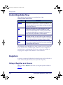
Controlling Data Flow .....................................................................................................
Registers ......................................................................................................................
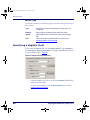
Using a Register as a Source .....................................................................................
Register Fields.........................................................................................................
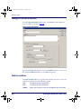
Using a Register as a Destination ...............................................................................
Write Type........................................................................................................
Specifying a Register Field ........................................................................................
Register Example: Parsing Data .................................................................................
Files .............................................................................................................................
Using a File as a Source............................................................................................
Data Location..........................................................................................................
Using a File as a Destination......................................................................................
Write Type........................................................................................................
Templates.....................................................................................................................
iv
77
78
78
78
79
79
80
80
81
81
82
82
83
84
84
PT Program Generator (PPG) v5.0
2342.book Page v Thursday, July 22, 2004 8:35 AM
Template Uses ........................................................................................................
Creating a Template ................................................................................................
Modifying an existing template ..................................................................................
Template Example: Modifying Inventory .....................................................................
Fields ...........................................................................................................................
Using Fields in Templates .........................................................................................
84
85
86
86
87
88
PT40 Communication............................................................................ 89
Overview ......................................................................................................................
Downloading the Application to the PDT ............................................................................
What Happens During a Download?............................................................................
Specialized Download Situations ................................................................................
Using XFER32................................................................................................................
XFER32 Setup .........................................................................................................
General Tab......................................................................................................
Transfer Tab .....................................................................................................
Logging Tab......................................................................................................
Sending and Receiving Data......................................................................................
Transmit (Send) Files.........................................................................................
Receive Files.....................................................................................................
89
89
91
92
92
92
93
94
96
96
97
98
PPG Tutorial ......................................................................................... 99
Overview ...................................................................................................................... 99
Studying a Sample Program .......................................................................................... 100
Building a Custom Portable Program............................................................................... 106
Creating Frames and Links...................................................................................... 106
Creating Frames.............................................................................................. 106
Creating Links................................................................................................. 107
Main Menu Access ........................................................................................... 108
Creating the Main Menu Nodes ................................................................................ 109
Saving Your Program ............................................................................................. 113
Creating and Setting Up the Collect Data Nodes......................................................... 113
The Display: Enter Item Node ........................................................................... 115
The Input: Item Node ...................................................................................... 115
The Verify: Input Node..................................................................................... 118
The Output: Error Beep Node ............................................................................ 119
The Display: Error Text Node ............................................................................ 119
The Copy: To File Node .................................................................................... 120
Creating and Setting Up the Upload Data Nodes ........................................................ 121
The Menu: Confirmation Node ........................................................................... 122
The Output: to PC Node ................................................................................... 122
The Output: Error Beep Node ............................................................................ 123
The Menu: Error Text Node............................................................................... 123
The Display: Successful Node............................................................................ 124
The Input: Timeout Display Node ...................................................................... 124
The Modify: Erase File Node.............................................................................. 125
Loading and Using the Program ..................................................................................... 126
Loading the Program onto the Portable ..................................................................... 126
Using the Program on the Portable........................................................................... 126
Creating and Using Templates ....................................................................................... 128
Creating the New Nodes ......................................................................................... 129
Creating the Fields................................................................................................. 131
User’s Guide
v
2342.book Page vi Thursday, July 22, 2004 8:35 AM
Example Frames ................................................................................. 135
Setting the Date and Time ............................................................................................
Changing the Auto-Off Timeout......................................................................................
Displaying the Contents of a Register .............................................................................
Sample Verification Methods..........................................................................................
Verifying a Numeric Value .......................................................................................
Verifying that a Number is an Integer .......................................................................
Verifying Input Size ...............................................................................................
Downloading a File to a PSC Portable ..............................................................................
Finding the Number of Records in a File ..........................................................................
Searching for a Partial Match .........................................................................................
Searching for Data in a File ...........................................................................................
Splitting Records into Two Files......................................................................................
Referencing Two Different Files ......................................................................................
Reviewing a File...........................................................................................................
Sounding a Beep..........................................................................................................
Padding a Number with Leading Zeros ............................................................................
136
136
137
138
138
139
142
145
147
148
149
151
153
155
157
157
The PPG Library.................................................................................. 159
Overview .................................................................................................................... 159
PPG Program Source Files ............................................................................................. 159
PPG System Commands...................................................................... 163
Overview .................................................................................................................... 163
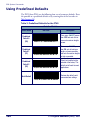
Using Predefined Defaults ............................................................................................. 164
Alternate Parameters.................................................................................................... 165
ASCII/Hex Conversion Table.............................................................. 167
Useful Bar Codes ................................................................................ 169
Troubleshooting ................................................................................. 171
Overview ....................................................................................................................
Fixing Corrupted Files ...................................................................................................
Downloading the Program to the Portable........................................................................
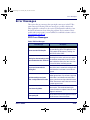
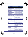
Error Messages ............................................................................................................
PPG Error Messages .........................................................................................
PPGComp Error Messages .................................................................................
PPGXfer Error Messages ...................................................................................
Technical Support ........................................................................................................
PSC Website Support .......................................................................................
PSC Website TekForum ....................................................................................
Reseller Technical Support ................................................................................
Telephone Technical Support.............................................................................
171
171
172
173
173
175
176
178
178
178
178
178
Glossary ............................................................................................. 179
Index .................................................................................................. 183
vi
PT Program Generator (PPG) v5.0
2342.book Page vii Thursday, July 22, 2004 8:35 AM
PSC Inc.
PT Program Generator
(PPG) Software End User
License Agreement
NOTICE TO END USER: PSC is providing you with a license for the Software you have acquired, subject to the terms and
conditions of this Agreement. If you use the Software, you will be deemed to have accepted the terms and conditions of this
Agreement. If you do not intend to be bound by the terms of this Agreement, PSC is not willing to license the Software to you, you
may not use or copy the Software, and you must contact the party from whom you acquired the Software promptly for instructions.
This End User License Agreement (“Agreement”) is a legally binding agreement governing the licensing of the Software by PSC Inc. and its
wholly owned subsidiaries and affiliates (“PSC”) to the entity or person who has acquired the Software (“End User”). For purposes of this
Agreement, “Software” means the PT Program Generator, whether obtained directly or indirectly from PSC, including any related update or
upgrade such as enhancements or modifications, and including all accompanying documentation. Any software that is associated with a
separate end-user license agreement is licensed to you under the terms of that license agreement. PSC and End User hereby agree as follows:
1. Scope of License Granted.
1.1 PSC grants to End User a non-exclusive, non-transferable, perpetual license to use the Software, in machine-readable form only, solely for
End User's internal business purposes. This Agreement does not convey ownership of the Software to End User. Title to the Software shall be
and remain at all times with PSC or any third party from whom PSC has obtained a licensed right.
1.2 Each Software license permits End User to install the Software on a single computer only. A separate Software license must be acquired for
each computer on which the Software operates.
1.3 End User may make one copy of the Software for backup purposes, provided that End User reproduces all proprietary notices on the copy,
including patent, copyright, trademark, and other similar notices of PSC's proprietary interest in the Software.
1.4 End User shall not sell, assign, sublicense, distribute, lend, rent, give, or otherwise transfer the Software to any third party unless such third
party agrees with PSC in writing to be bound by the terms and conditions of this Agreement. Any such transfer of the Software absent such
agreement shall be null and void.
1.5 Other than as provided in this Agreement, End User shall not copy or modify the Software. Under no circumstances shall End User
decompile, disassemble, reverse engineer, or otherwise reproduce or remanufacture the Software, whether modified or unmodified, without
PSC's prior written consent.
1.6 Any copying, installing, reproduction, reverse-engineering, electronic transfer, or other use of the Software 1) on other than the number of
computers for which End User has paid for a Software license, or 2) on any non-PSC equipment, will be a material breach of this Agreement.
However, PSC may elect not to terminate this Agreement or the granted license, but instead may elect to notify End User that End User is
deemed to have ordered and accepted a license for each breaching use. End User shall pay PSC the applicable list price fees for each such
license as of the date of breach as determined by PSC.
User’s Guide
vii
2342.book Page viii Thursday, July 22, 2004 8:35 AM
(PPG) Software End User License Agreement
2. Intellectual Property.
End User acknowledges that the Software constitutes valuable trade secrets of PSC and that the Software is protected by intellectual property
laws and treaties. The license set forth in this Agreement does not transfer to End User any ownership of PSC's copyrights, patents, trademarks,
service marks, trade secrets, or other intellectual property rights and End User shall have no right to commence any legal action to obtain such
rights. End User shall not remove, modify, or take any other action that would obscure any copyright, trademark, or other intellectual property
notices contained in the Software.
3. Proprietary Information.
3.1 “Proprietary Information” means all (a) source code, object code, software, documentation, and any related internal design, system design,
data base design, algorithms, technology, technical data or information, implementation techniques, and trade secrets related to the Software,
(b) any other trade secrets marked appropriately or identified as proprietary or confidential, and (c) any information that End User, under the
circumstances, should recognize as confidential. Proprietary Information does not include any information that the receiving party can establish
was (1) in the public domain, (2) already in the receiving party's possession or rightfully known prior to receipt, (3) rightfully learned from a third
party not in violation of any other's proprietary rights, or (4) independently developed.
3.2 End User acknowledges that Proprietary Information is the confidential, proprietary, and trade secret property of PSC and End User
acquires no right or interest in any Proprietary Information.
3.3 End User shall not disclose, provide, or otherwise make available PSC's Proprietary Information to any person other than End User's
authorized employees or agents, all of whom must be under confidentiality agreement at least as restrictive as the terms of this Section 3, and
End User shall not use the Proprietary Information other than in conjunction with use of the Software exclusively for End User's internal business
purposes. End User shall take steps to protect the Proprietary Information no less securely than if it were End User's own intellectual property.
3.4 The provisions of this Section shall survive and continue for five (5) years after the termination of this Agreement.
4. Limited Warranty.
4.1 PSC warrants that, under normal use and operation, the Software will conform substantially to the applicable documentation for a period of
thirty (30) days from delivery to End User. During this period, for all reproducible nonconformities for which PSC has been given written notice,
PSC will use commercially reasonable efforts to remedy nonconformities determined by PSC. End User agrees to supply PSC with all
reasonably requested information and assistance necessary to help PSC in remedying such nonconformities. For all defects reported to PSC
within the warranty period, PSC's liability is limited to providing End User with one copy of corrections or refunding the amount End User paid for
the Software license, at PSC's discretion, and responding to End User's software problem reports according to PSC's standard assistance
practices. PSC does not warrant that the Software will meet End User's requirements or that use of the products will be uninterrupted or error
free, or that PSC's remedial efforts will correct any nonconformance. This limited warranty does not cover any software that has been
customized, subjected to damage or abuse, whether intentionally, accidentally, or by neglect, or to unauthorized repair, unauthorized alteration,
or unauthorized installation, and shall be void if End User modifies the Software, uses the Software in a manner other than as established in the
applicable documentation, or if End User breaches any of the provisions of this Agreement.
4.2 THE SOFTWARE IS PROVIDED “AS IS” AND, EXCEPT AS PROVIDED IN THIS SECTION, PSC MAKES NO WARRANTIES OF ANY
KIND, EXPRESS OR IMPLIED, WRITTEN OR ORAL, WITH RESPECT TO THE SOFTWARE, AND SPECIFICALLY DISCLAIMS THE IMPLIED
WARRANTIES OF MERCHANTABILITY AND FITNESS FOR A PARTICULAR PURPOSE.
5. Infringement.
5.1 PSC will defend End User against any claim in a lawsuit that the Software furnished hereunder infringes a United States patent or copyright
of a third party and PSC will pay any damages finally awarded against End User by a court of competent jurisdiction that are attributable to such
claim or will pay End User's part of any settlement that is attributable to such claim, provided, that 1) End User notifies PSC promptly in writing
of the claim, 2) PSC controls the defense or settlement of the claim, and 3) End User cooperates fully with PSC in such defense or settlement.
All notices of a claim should be sent to PSC Inc., Legal Department, 111 SW Fifth Ave. Suite 4100, Portland, OR 97204-3644.
5.2 In the defense or settlement of any such claim, PSC may, at its option, 1) procure for End User the right to continue using the Software, 2)
modify the Software so that it becomes non-infringing, 3) replace the Software with an equivalent product not subject to such claim, or 4) provide
End User an opportunity to return the Software and receive a refund of the amount End User paid for the Software license, less a reasonable
allowance for use.
viii
PT Program Generator (PPG) v5.0
2342.book Page ix Thursday, July 22, 2004 8:35 AM
PT Program Generator
5.3 PSC shall have no liability to End User for claims of infringement based upon 1) the use of the Software in combination with any product
which PSC has not either furnished or authorized for use with such Software, 2) the use of any Software designed, manufactured, or modified to
the specifications of End User, or 3) End User's customization or modification of the Software.
5.4 THE FOREGOING STATES PSC'S COMPLETE AND ENTIRE OBLIGATION TO END USER CONCERNING CLAIMS OF INTELLECTUAL
PROPERTY INFRINGEMENT, CANCELS AND SUPERCEDES ANY PRIOR AGREEMENTS, WHETHER ORAL OR WRITTEN, BETWEEN
PSC AND END USER CONCERNING SUCH CLAIMS, AND WILL NOT BE MODIFIED OR AMENDED BY ANY PAST,
CONTEMPORANEOUS, OR FUTURE AGREEMENTS OR DEALINGS BETWEEN PSC AND END USER, WHETHER ORAL OR WRITTEN,
EXCEPT AS SET FORTH IN A FUTURE WRITING SIGNED BY AN AUTHORIZED REPRESENTATIVE OF EACH PARTY.
6. Limitation of Liability.
PSC'S LIABILITY FOR DAMAGES, IF ANY, WHETHER BASED UPON CONTRACT, TORT (INCLUDING NEGLIGENCE), PRODUCT
LIABILITY, STRICT LIABILITY, WARRANTY, OR ANY OTHER BASIS, SHALL NOT EXCEED THE AMOUNT END USER PAID FOR THE
SOFTWARE LICENSE. UNDER NO CIRCUMSTANCES SHALL PSC BE LIABLE FOR LOST PROFITS, LOST DATA, INTERRUPTION OF
SERVICE, OR FOR ANY SPECIAL, CONSEQUENTIAL, CONTINGENT, INDIRECT, INCIDENTAL, PUNITIVE, EXEMPLARY, OR OTHER
SIMILAR DAMAGES, EVEN IF PSC HAS BEEN ADVISED OF THE POSSIBILITY OF SUCH DAMAGES.
7. Technical Support.
End User is entitled to one (1) free technical support call in connection with End User's use of the Software. Technical support does not include
assisting End User in developing applications. End User may obtain additional support for the Software from PSC at PSC's standard support
fees and under PSC's standard support terms and conditions in effect at the time End User acquires the Software.
8. Government Restricted Rights; International Use.
The Software is provided with Restricted Rights. Use, duplication, or disclosure by the U.S. Government is subject to the restrictions for
computer software developed at private expense as set forth in the U.S. Federal Acquisition Regulations at FAR 52.227-14(g), or 52.227-19 or in
the Rights in Technical Data and Computer Software clause at DFARS 252.227-7013(c)(1)(ii), whichever is applicable. If End User uses the
Software outside the United States, End User must comply with the local laws of the country in which the Software is used, with U.S. export
control laws, and with the English language version of this Agreement. The provisions of the “United Nations Convention on International Sale of
Goods” shall not apply to this Agreement.
9. Termination.
9.1 Either party may terminate this Agreement or any license granted under this Agreement at any time upon written notice if the other party
breaches any provision of this Agreement.
9.2 Upon termination of this Agreement, End User immediately shall cease using the Software and shall return to PSC or destroy all Software
covered by this Agreement, and shall furnish PSC with a certificate of compliance with this provision signed by an officer or authorized
representative of End User.
10. General Provisions.
10.1 Entire Agreement; Amendment. This Agreement contains the entire agreement between the parties relating to the Software and
supersedes all prior or contemporaneous agreements, written or oral, between the parties concerning the Software. This Agreement may not be
changed, amended, or modified except by written document signed by an authorized representative of each party.
10.2 Notice. All notices required or authorized under this Agreement shall be given in writing, and shall be effective when received, with
evidence of receipt. Notices shall be sent to End User at such address as End User shall provide to PSC in writing, and shall be sent to PSC
Attn: Contract Administration, PSC Inc., 959 Terry Street, Eugene, OR 97402.
10.3 Waiver. A party's failure to enforce any of the terms and conditions of this Agreement shall not prevent the party's later enforcement of such
terms and conditions.
10.4 Governing Law. This Agreement shall be governed by the laws of the State of Oregon, United States of America, excluding choice of law
provisions.
10.5 Attorneys Fees. In the event an action is brought to enforce the terms and conditions of this Agreement, the prevailing party shall be
entitled to reasonable attorneys' fees, both at trial and on appeal.
-END-
User’s Guide
ix
2342.book Page x Thursday, July 22, 2004 8:35 AM
(PPG) Software End User License Agreement
NOTES
x
PT Program Generator (PPG) v5.0
2342.book Page 1 Thursday, July 22, 2004 8:35 AM
Chapter 1
Introduction
This document assumes that you are familiar with Microsoft Windows®. If you do not
know how to launch applications, select menu options, or use dialog boxes, please
refer to your Microsoft Windows documentation before proceeding with PPG.
Document Overview
This document is divided into seven chapters and eight appendices:
•
Introduction on page 1, provides an overview of PPG, describes the conventions used in this manual, and tells how to access PSC Technical
Support.
•
Getting Started on page 5, tells you how to install and run PPG. It also
gives you an overview of PPG concepts and usage.
•
PPG Application Design on page 15, provides information on program-
ming concepts including how to design your program, define program modules and specify program flow.
•
The PPG Menubar on page 23 describes the PPG menubar and how to
access all PPG’s features using the menubar, including creating, saving
and editing applications.
•
Creating & Using Nodes on page 49, gives you detailed information on
Frames, Subroutines, Nodes, and Links.
•
Managing Data on page 77, describes the use of Registers, Fields, Files,
and Templates.
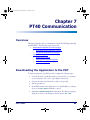
•
PT40 Communication on page 89, show you how to download applica-
tions to the PDT and how to transfer data to and from the portable
device.
•
User’s Guide
PPG Tutorial on page 99, is a step-by-step tutorial to use in learning PPG.
1
2342.book Page 2 Thursday, July 22, 2004 8:35 AM
Introduction
•
Example Frames on page 135, contains sample code for commonly used
functions.
•
The PPG Library on page 159, describes the applications that come with
PPG.
•
PPG System Commands on page 163, identifies the system commands
that can be used with PPG.
•
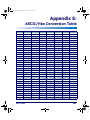
ASCII/Hex Conversion Table on page 167, contains a table of ASCII charac-
ters for your reference.
•
Useful Bar Codes on page 169, contains bar codes that can be used to
program your portable data collection unit.
•
Troubleshooting on page 171, provides troubleshooting information and
table of possible error messages.
•
Glossary on page 179, is a glossary of the specific PPG programming
terms used in this manual.
Style Conventions
Formatting conventions are used throughout this document to provide a consistent method for representing various screen shots, buttons, controls, keyboard characters, notes, and cautions while you are working with PPG.
Manual Formatting Conventions
Keyboard Keys
Keyboard keys, such as ENTER, are in Bold. When keyboard keys are Linked
with a plus sign (for example, SHIFT+ENTER, or Ctrl+C), hold down the first
key while pressing the second key once.
Keystrokes
Input characters, filenames, file paths, field selections from a pull-down list,
and data or keystrokes entered by the user are shown in courier bold.
Input characters are usually given in lowercase (no capital letters); you may
enter them in lowercase, uppercase, or a combination. When input characters
are given in uppercase or a combination of lowercase and uppercase, type the
characters exactly as shown.
2
PT Program Generator (PPG) v5.0
2342.book Page 3 Thursday, July 22, 2004 8:35 AM
Style Conventions
Windows Controls
Words in Bold are selections that appear in the PPG program, such as frame
names, subroutine names, node names, file, field, template, and register
names, menu options, buttons, dialog boxes, field names, and radio-buttons.
Words in Bold separated by an arrow (>) are menu actions you make in the
order provided. For example, File > Run means select the File menu and then
select Run from that menu.
Cautions indicate an action where there is a possibility of damage to data integrity or
data failure. Cautions always have the Caution icon to the left.
CAUTION
Notes provide additional information on a topic, including technical details, exceptions to instructions and other pertinent information. Notes always have the notepad
icon to the left.
Mouse Actions
Click or Select
Press and immediately release the left mouse button without moving
the mouse. Clicking is used to select specific buttons on various forms
and tables.
Double Click
Click the left mouse button twice in rapid succession. Used to initiate an
application.
Right Click
Press and hold the right mouse button without moving the mouse.
Portable Keys
Keys on the portable data terminal (PDT) unit are bracketed with < >, to identify that they refer to the portable data collection unit, rather than the PC.
User’s Guide
<F1> — <F8> Keys
The Function keys, <F1> – <F8>, are used specifically on the
PT40 portable data collection units.
<ENTER> Key
To differentiate the <ENTER> key on the portable from the Enter
key on the PC’s keyboard, portable keys are formatted as “press
<ENTER>”.
3
2342.book Page 4 Thursday, July 22, 2004 8:35 AM
Introduction
NOTES
4
PT Program Generator (PPG) v5.0
2342.book Page 5 Thursday, July 22, 2004 8:35 AM
Chapter 2
Getting Started
Overview
Refer to this section as you prepare to install and use the PT Program Generator (PPG). The following general topics are covered:
•
•
Before You Start on page 6
•
•
•
What’s New in PPG v5.0? on page 6.
•
•
•
•
•
•
PPG System Requirements on page 6.
Registering Your Copy of PPG on page 6.
PPG Installation on page 6
Required Hardware on page 6.
Operating Systems on page 7.
Supported Portables on page 7.
Installing PPG on page 7.
•
Upgrading to PPG v5.0 on page 8.
Launching and Exiting PPG on page 8
•
Overview of PPG on page 9
•
•
•
•
•
•
•
User’s Guide
PPG License Agreement on page 6.
PPG Tutorial on page 10.
User Interface on page 11.
Menus and Toolbars on page 11.
PPG Toolbar Buttons on page 11.
Program Nodes Toolbar on page 12.
Working with PPG Windows on page 13.
•
Navigation on page 13.
Generating the Program on page 14.
•
Downloading the Program on page 14.
•
Transferring Data on page 14.
5
2342.book Page 6 Thursday, July 22, 2004 8:35 AM
Getting Started
Before You Start
What’s New in PPG v5.0?
The following features are new to this version of PPG:
•
PPG v5.0 works with PSC’s Falcon PT40.
•
Improved user interface provides buttons to access program nodes and
controls.
•
Double-byte language support for Chinese Simplified and Chinese
Traditional characters.
PPG License Agreement
Review the license agreement; it gives you permission to copy the program
files for backup purposes only. You may not make a copy for another person to
use. When you open the envelope that contains the software, this means that
you agree to the terms of the license agreement.
Registering Your Copy of PPG
PSC values your feedback. Please take a few moments and complete the Product Registration form located on PSC's website or on the PSC Manuals CD.
Registering your products ensures that you will be informed of the latest product news, software updates and other future developments from PSC.
PPG Installation
PPG System Requirements
PPG runs with the minimum hardware and operating system requirements
listed below. For maximum performance, install PPG onto a computer with a
higher speed processor and more memory than the minimum requirements.
Required Hardware
The following equipment is required to run PPG:
6
•
Processor - 450MHz
•
Memory - 12MB
•
Hard Disk - 10MB
PT Program Generator (PPG) v5.0
2342.book Page 7 Thursday, July 22, 2004 8:35 AM
PPG Installation
•
Video - VGA
•
A CD-ROM drive
•
A serial port (for loading your program into a portable)
Operating Systems
PPG works with the following Microsoft® Windows® operating systems:
•
Windows® 98 (SP5)
•
Windows® 2000 (full double-byte functionality)
•
Windows® Me (SP5)
•
Windows® NT (SP6)
•
Windows® XP (full double-byte functionality)
Supported Portables
PPG v 5.0 only supports the PSC Falcon PT40. A compatible docking station
or communications cable is required for the PDT to work with PPG. Contact
a portable data collection supplier to purchase the required equipment and
accessories.
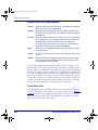
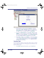
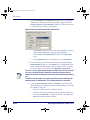
Installing PPG
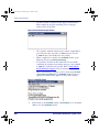
Complete the following steps in the installation utility to install PPG:
1. Insert the PPG Installation disk into your PC’s CD drive. A Welcome
screen opens.
2. Press Next on the Welcome screen to continue the installation.
3. Press Yes, I Accept at the License Agreement screen to continue the
PPG installation process and accept the PPG license agreement.
4. At the Destination Location screen, select the PPG destination directory:
PPG installs to C:\Program Files\PSC\PPG50 by
default.
• Press the Browse button to select or create another directory in
which to install PPG.
5. Press Next to select the installation of the PT40 software and PPG.
•
6. Press Next to begin the installation of PPG. A series of Installing....
screens appear.
User’s Guide
7
2342.book Page 8 Thursday, July 22, 2004 8:35 AM
Getting Started
7. Finally, a message that PPG has been successfully installed is displayed.
8. Press Finish to exit the installation.
Upgrading to PPG v5.0
If you want to upgrade to PPG v5.0, complete the instructions in Installing PPG
on page 7. By default, PPG v5.0 is installed in a different default location on
your PC’s hard drive than PPG v4.5, so it is possible to have both versions
installed at the same time.
Prior PPG version source files (*.scr) are converted when you open and save
them in PPG v5.0. To maintain PPG v4.5 compatible applications, open them
in PPG v5.0 and save them with a new name or new location.
There is no keyboard wedge support in PPG v5.0. Applications created in previous
versions of PPG that use the keyboard wedge option can be saved in PPG v5.0, but
they must be updated with a new input method after you save them.
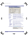
Uninstalling PPG
To uninstall PPG, use the standard method of removing programs installed on
Microsoft Windows:
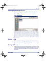
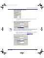
1. From the Windows Start menu, select Settings > Control Panel > Add/
Remove Programs.
2. At the Add/Remove Programs window, select Change or Remove Programs along the left side of the window.
3. Scroll down the screen until you locate PT Program Generator and
select it by clicking on it with your mouse.
4. Press Change/Remove to initiate the program removal process.
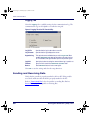
Launching and Exiting PPG
Launching PPG
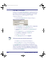
To launch PPG, complete the following steps:
1. Select PPG from your Windows Start Menu > PT Program Generator
> PT Program Generator.
8
PT Program Generator (PPG) v5.0
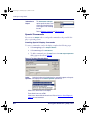
2342.book Page 9 Thursday, July 22, 2004 8:35 AM
Overview of PPG
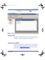
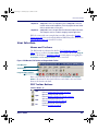
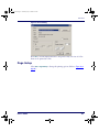
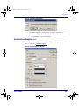
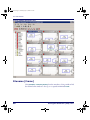
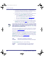
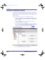
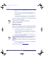
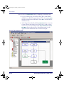
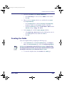
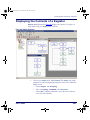
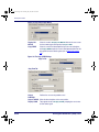
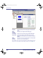
2. The PPG window opens as illustrated in Figure 1 with a new, blank
PPG application.
Figure 1. The PPG Window
Exiting PPG
To exit PPG, select File > Exit from the menubar or double-click on the Control-menu box. A dialog appears, asking if you want to save any changes to the
current file. Select Yes to save changes or No to discard them.
Overview of PPG
Use PPG to construct and design an application for your PSC portable. You
can create custom applications to collect, verify, and store data. Designing and
creating the program is the first part of the process; there are several steps
involved. Refer to PPG Application Design on page 15 for an overview of using
PPG to construct an application for your PSC portable.
User’s Guide
9
2342.book Page 10 Thursday, July 22, 2004 8:35 AM
Getting Started
PPG Tutorial
To become familiar with PPG, complete the PPG Tutorial on page 99, or access
the PPG Tutorial via the on-line help.
Program Files
Executable Programs
Following is a list of executable programs that are installed on your PC during
the installation of PPG:
PPG
PPG is the PT Program Generator application. This is the application you
use to create programs for a PSC portable.
PPGXFER
PPGXFER is used to transfer the program you created in PPG to the portable. This utility is called automatically by PPG when you download a program
to the portable. Refer to Downloading the Application to the PDT on page 89
and Specialized Download Situations on page 92.
PPGComp
PPGComp (PPG Compiler) is used to compile the program you created into
the format which is downloaded to the PDT. This utility is called automatically
by PPG when you download a program to the portable. Refer to Downloading the Application to the PDT on page 89.
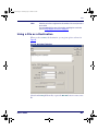
XFER32
XFER32 is used to transfer data between a PC and the portable. After you
input data or scan bar codes with the portable, you can use this utility to
upload the data into a file on your PC. You can also use it to download information stored in a PC file into the portable. Refer to Using XFER32 on
page 92.
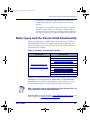
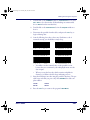
Sample Program Files
PPG comes with four sample files. Some of these files are just portions of programs demonstrating use of a specific node. However, you can use any of these
samples as a foundation for building a full-size program:
10
sample.scr
sample.scr allows you to collect information with your portable,
upload collected data to a PC, and erase collected data. You will be using
this file as you work through PPG Application Design on page 15 and the
PPG Tutorial on page 99.
sample2.scr
sample2.scr is a simple but complete data-collection program that
allows the user to enter data as either item-and-quantity values or just item
values. The program also stores data, uploads data, and erases data.
PT Program Generator (PPG) v5.0
2342.book Page 11 Thursday, July 22, 2004 8:35 AM
Overview of PPG
sample3.scr
sample3.scr is an expanded version of sample2.scr that
includes review and edit capabilities. (This is the program that was loaded
with your portable when you first got it.)
sample4.scr
sample4.scr is an application which illustrates multiple frame levels.
This example is useful as a model for designing complex applications.
PPG also comes with some example frames and files, discussed in Example
Frames on page 135. You can download additional PPG library files, discussed in
The PPG Library on page 159, from PSC’s website.
User Interface
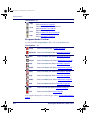
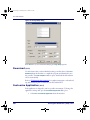
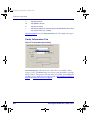
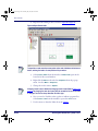
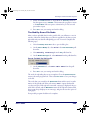
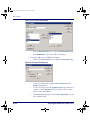
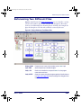
Menus and Toolbars
The PPG menubar is discussed in detail in The PPG Menubar on page 23. In
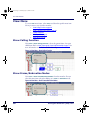
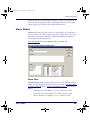
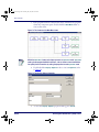
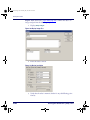
Figure 2, the top toolbar is the PPG toolbar. The second toolbar is the Program
Nodes toolbar. Refer to View Menu on page 38 for information on toggling the
PPG toolbar and the Program Nodes toolbar on and off.
Figure 2. PPG Menubar, PPG Toolbar, and Program Nodes Toolbar
PPG Menubar
PPG Toolbar
Program Nodes Toolbar
Refer to the following tables for descriptions of PPG toolbar and Program
toolbar buttons, their basic functions, and a Link to the section that
discusses the function in detail.
Nodes
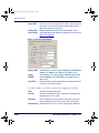
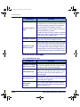
PPG Toolbar Buttons
Click this Button To
Create a new PPG flow chart file.
New
Refer to Creating a New File (Ctrl+N) on page 24.
Open an existing PPG flow chart file.
Open
Refer to Opening an Existing File (Ctrl+O) on page 25.
Save an existing PPG flow chart file.
Save
Refer to Saving a File (Ctrl+S) on page 25.
Cut the selected node to the clipboard.
Cut
Refer to Cut (Ctrl+X) on page 35.
User’s Guide
11
2342.book Page 12 Thursday, July 22, 2004 8:35 AM
Getting Started
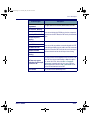
Click this Button To
Copy the selected node to the clipboard.
Copy
Refer to Copy (Ctrl+C) on page 35.
Paste the cut or copied node to the flow chart.
Paste
Refer to Paste (Ctrl + V) on page 35.
Open the Print dialog box.
Print
Refer to Printing a File (Ctrl+P) on page 26.)
Open the PPG online Help file.
Help
Refer to PPG Help (F1) on page 47.
Program Nodes Toolbar
To create new PPG Program Nodes, click on the node’s Create button:
Click this Button
To
Frame
Create a new Frame. (Refer to Frames on page 50.)
Subroutine
Create a new Subroutine. (Refer to Subroutines on page 51.)
Menu
Create a new Menu node. (Refer to Menu Nodes on page 55.)
Display
Create a new Display node. (Refer to Display Nodes on page 56.)
Input
Create a new Input node. (Refer to Input Nodes on page 57.)
Output
Create a new Output node. (Refer to Output Nodes on page 60)
Verify
Create a new Verify node. (Refer to Verify Nodes on page 63.)
Copy
Create a new Copy node. (Refer to Copy Nodes on page 66.)
Modify
Create a new Modify node. (Refer to Modify Nodes on page 67.)
Math
Create a new Math node. (Refer to Math Nodes on page 69.)
Call
Create a new Call node. (Refer to Call Nodes on page 72.)
Link
Create a new Link. (Refer to Links on page 73.)
For a complete description of each node type, refer to Creating & Using Nodes on
page 49.
12
PT Program Generator (PPG) v5.0
2342.book Page 13 Thursday, July 22, 2004 8:35 AM
Overview of PPG
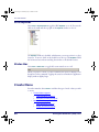
Navigation
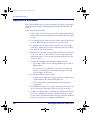
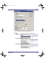
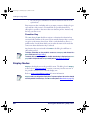
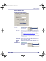
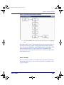
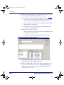
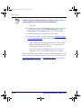
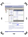
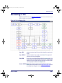
If your flow chart is larger than the PPG window, use the scroll bars and cursor
keys to scroll different areas into view. (refer to Figure 3 on page 13). Or use your
mouse to expand the window size by clicking and dragging on the beveled
lower right corner of the PPG window.
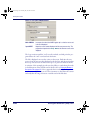
Working with PPG Windows
To expand the PPG window to fill the screen, or the PPG Application to fill
the PPG window, select the Maximize button in the upper right corner of the
window.
To temporarily remove the PPG window from your screen without exiting the
application, select the Minimize button. The window becomes an application
icon in the Windows taskbar. Click on the taskbar icon to bring the window
back exactly as you left it.
Figure 3. Scroll bars on a Flow Chart
User’s Guide
13
2342.book Page 14 Thursday, July 22, 2004 8:35 AM
Getting Started
For information on working in application windows, including using scroll bars and
selecting menu commands, refer to your Microsoft Windows documentation.
Generating the Program
Refer to PPG Application Design on page 15 for an overview of using PPG to create
a PDT application, starting with a flow chart of your data-collection process.
Creating & Using Nodes on page 49 provides details on each program node type.
Downloading the Program
Once you have created a PDT application using PPG, connect your portable
to a PC and use the Download Program command to load the program into
the portable unit. PPGComp compiles the program automatically, translating
it into code that is understood by the portable, and then sends the program via
the cable to your portable. After the application has been downloaded to the
portable, you are now ready to collect data with the portable.
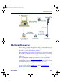
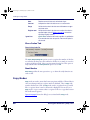
Transferring Data
After you have input data or scanned a series of bar codes with the programmed portable data collection unit, you can use XFER32 to transfer the collected data to a file on your PC. The data is uploaded via the serial cable to a
specified file on your computer. You can also transfer data, such as a pick list
for comparing input data, from the PC to the portable. For detailed instructions, refer to PT40 Communication on page 89.
Collected data is usually a series of numbers or alphanumeric strings stored in
a file until you transfer it into a data processing program. For example, a
scanned bar code that reads 107-028-0274, once filtered through a program set up to interpret it, is translated into more readable information, such
as DOCKERS T-LG, $25.60.
You can program the portable to translate scanned numbers into words, but
this is usually done with your data processing program. For example, you can
load the data into a spreadsheet program that performs calculations. Or use a
database program that tracks your inventory. Use PPG to format collected data
into human recognizable information.
14
PT Program Generator (PPG) v5.0
2342.book Page 15 Thursday, July 22, 2004 8:35 AM
Chapter 3
PPG Application Design
Overview
This chapter provides an overview of the process of designing and building an
application using PPG. The following topics are covered:
•
•
Designing the Application on page 15.
•
Application Output on page 15.
•
Application Structure on page 16
Node Types and the Parent-Child Relationship on page 17.
•
Creating Function Nodes on page 18
•
Creating Operation Nodes on page 18
•
Actual vs. Virtual Display on page 19.
•
Defining Program Flow on page 20.
•
Sending and Receiving Files on page 20.
•
Additional Resources on page 21.
Designing the Application
Application Output
Before you begin to design an application, you must decide how the resulting
data will be handled. You probably have a good idea of how you would like the
collected data to be output. The result of the application is usually a file of collected data, so you must determine the purpose of the file and how it is organized; this determines what data is collected and how. You may want to
examine portions of collected data or work with data files downloaded into the
PT40. After you have determined the data output format, you can begin to
define the program steps and flow.
User’s Guide
15
2342.book Page 16 Thursday, July 22, 2004 8:35 AM
PPG Application Design
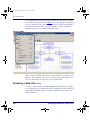
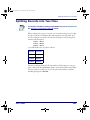
Application Structure
Next you must decide what you want the program to do. Draft a program flow
chart with pencil and paper, while keeping in mind the following ideas and
concepts.
Follow them as steps if you like:
1. List the major actions the user may take. These may include reading
data from the scanner, uploading data from the PDT, and storing data
in a file.
2. For each major action, define each step. In what order will the actions
be taken? Walk through each step as if you were the end user.
3. Do multiple actions contain the same step? If so, save time and program size by putting these steps into a subroutine that can be called
from different areas of the program.
4. Will each action be taken in a specific order or will the user be allowed
to choose an action? To offer a choice of actions, such as collecting
and uploading data, you can provide a menu that will allow the user
to select an action.
5. Visualize the individual steps involved in each major action.
•
For example, will the user be collecting different types of data at
different times?
•
For each action you would take as a portable user, imagine the
options you would expect to have and the messages you would
expect to appear on the screen.
6. In what order will the actions be taken?
•
Is there an obvious direction to the program? For example, a user
would normally collect data and then upload it.
•
This order should be reflected in the main menu and in the
program flow.
7. How will the user start? Do you want to identify the user first by asking for a password or ID number? What about a log-on message?
8. To make your design clearer, try breaking your design up into logical
sections. As a guideline, if a function contains more than ten steps,
you may want to break it down further. Keeping each frame small will
make your program easier to implement and maintain.
16
PT Program Generator (PPG) v5.0
2342.book Page 17 Thursday, July 22, 2004 8:35 AM
Node Types and the Parent-Child Relationship
•
For example, an application with collect and store functions
would be broken up into a collection function and a storage
function.
•
For example, a storage function may contain steps to verify the
data meets certain criteria, store the data in a file and track the
amount of data stored. This may, depending on the complexity of
each step, be broken up into functions which perform each step.
Node Types and the Parent-Child Relationship
Build your application in a modular fashion, taking advantage of the ParentChild relationship. There can be multiple levels in each program flow chart.
Any type of Operation node can exist at any level. The top level is the parent
and lower levels are children.
Table 1. Function and Operation Nodes
Function Nodes
Operation Nodes
Menu Nodes starting on page 5-55
Display Nodes starting on page 5-56
Input Nodes starting on page 5-57
Frames starting on page 5-50
Subroutines starting on page 5-51
Output Nodes starting on page 5-60
Verify Nodes starting on page 5-63
Copy Nodes starting on page 5-66
Modify Nodes starting on page 5-67
Math Nodes starting on page 5-69
Call Nodes starting on page 5-72
Applications constructed with PPG contain two general types of nodes, Function Nodes, which include Frames and Subroutines, and Operation Nodes.
Each Frame in a program flow chart represents a major function or option.
Connect Frames together in a logical way that indicates program flow.
While it is possible to create an entire application at the main frame level, this is not
the best approach for any but the smallest applications.
Operation Nodes are described briefly in Creating Operation Nodes on page 18, and
more completely in Creating & Using Nodes on page 49.
User’s Guide
17
2342.book Page 18 Thursday, July 22, 2004 8:35 AM
PPG Application Design
Creating Function Nodes
Once you’ve designed the basic program structure, the next step in generating
a portable program is to define each Function Node. Function Nodes are
frames or subroutines and are used to organize the steps and work of Operation Nodes. Most developers start by creating Function Nodes.
Frames
contain a set of program steps that are collected and ordered in a logical structure. Frames can consist of other frames, subroutines, and nodes.
Nodes are Linked together within the frame using Links.
Frames
Subroutines
Subroutines contain nodes that execute program steps, much like Frames, but
they can be called from anywhere in the application. They should be self-contained and perform functions that are used in multiple places in the application. Use Call nodes to link Subroutines to the location within the Operation
Node or Frame where they will be called.
Using Your Flow Chart
Using the flow chart you created in Application Structure on page 16, list the
Frames and Subroutines you will define. As a general guideline, if the function is used in multiple places, make it a Subroutine. Otherwise, it should be a
Frame. Once all Function Nodes are created, define each step by creating the
Operation Nodes.
Creating Operation Nodes
Each Operation Node represents a program step or work performed by the
application. After you have created the frames and subroutines, fill in the program steps for each function node. Using the flow chart, create an appropriate
Operation Node for each step in the Frame or Subroutine. There are nine different types of Operation Nodes to chose from, as shown in Table 1 on page 17.
18
PT Program Generator (PPG) v5.0
2342.book Page 19 Thursday, July 22, 2004 8:35 AM
Node Types and the Parent-Child Relationship
Actual vs. Virtual Display
The Falcon PT40's actual display screen is a window to a larger display area
called the virtual display (refer to Figure 4). Most applications you will use will
fit into the actual display. However, applications can sometimes contain data
longer than the default 6 line by16 character view of the actual display.
Figure 4. Virtual vs. Actual Display Using Default System Font
0,0
Actual Display
16 characters wide
80 characters wide
The shaded box
F1=NEXT F2=PRE
represents the PT40
REC#11 OF 16
display screen.
6 lines high 120850A30NME5274J400967629
25 lines high
F3=REV F4=EXIT
F1=NEXT F2=PRE
REC#12 OF 16
120850A30NME5274J400984019
F3=REV F4=EXIT
F1=NEXT F2=PRE
REC#13 OF 16
120850A30NME5274J400942885
F3=REV F4=EXIT
Virtual Display: The larger area represents the maximum size for the Virtual Display in some applications
(visible to the user only by using the arrow navigation keys)
Adding or changing character sizes changes the appearance of the actual display.
The number of lines and characters will vary with the character sizes.
The actual display screen shows only a portion of the available data in the virtual display. Use the arrow keys to navigate the actual display screen to view
the virtual display data. The text in the virtual display remains in place and the
actual display screen changes its view within the virtual display.
If you scan longer bar codes or enter more data than can fit in a single line of
the virtual display, the data automatically wraps to the next line. Because
applications for the PT40 can contain and use different fonts, the amount of
data that is available within the virtual display will vary.
User’s Guide
19
2342.book Page 20 Thursday, July 22, 2004 8:35 AM
PPG Application Design
The virtual display maintains the latest lines of data once all lines of the virtual
display are full. The oldest lines of data are “pushed off the top” as new data is
added at the bottom.
Defining Program Flow
After you create all the nodes, connect the program pieces together using Link
Nodes to define the flow of the program.
Links are shown on the PPG display with arrows which point from one step to
the next. Some nodes will have multiple entry and exit points. For example, a
Copy node can have either one or two exit points. You may choose to have
your application go to a Display node if an error occurs or, if the copy operation is successful, to continue on to a Menu node.
For information on the mechanics of creating, modifying and deleting Links,
refer to Links on page 73.
Refer to Data on page 43 for a brief overview of data types and Links to each
type’s description. For more detailed information on managing program data
or to specify a Data File, Field, Template, or Register, refer to Managing Data on
page 77.
Sending and Receiving Files
The final step in using PPG is to transfer the applications you have created to
the Falcon PT40. Refer to PT40 Communication on page 89 for more information
on sending and receiving files.
Figure 5 on page 21 is a flow chart showing the application generation, data flow,
file transfer process used when you create custom files with PPG and download them to your PSC Falcon PT40 from a PC.
20
PT Program Generator (PPG) v5.0
2342.book Page 21 Thursday, July 22, 2004 8:35 AM
Additional Resources
Figure 5. Application Generation, Data Flow & Transfer Process
Additional Resources
Before or after you complete the application design, to understand better how
to work with PPG to design and to create custom applications for your PSC
Falcon PT40, complete the PPG Tutorial on page 99.
Refer to Sample Program Files on page 10 for information on the four (4) sample
files included with the PPG software. You can open these files to see how they
are constructed, and use them as building blocks in constructing your own
application.
Refer to Example Frames on page 135 for information on the example frames
included with PPG. Refer to The PPG Library on page 159 for information on
sample PPG program source files which you can download from PSC’s website
that include examples of file manipulation, templates, and nodes.
You can download additional library files at no charge from the Technical Support area of PSC’s website at www.pscnet.com. Refer to The PPG Library on
page 159 for more information on these files.
User’s Guide
21
2342.book Page 22 Thursday, July 22, 2004 8:35 AM
PPG Application Design
NOTES
22
PT Program Generator (PPG) v5.0
2342.book Page 23 Thursday, July 22, 2004 8:35 AM
Chapter 4
The PPG Menubar
Overview
This section discusses the PPG menubar, located at the top left of the user
interface. The following menu items are reviewed:
•
File Menu on page 23.
•
Edit Menu on page 34.
•
View Menu on page 38.
•
Create Menu on page 40.
•
Window Menu on page 44.
•
Help Menu on page 47.
Refer to Menus and Toolbars on page 11 for a brief overview of the PPG menubar.
File Menu
The following sub-topics are covered in this section:
•
•
•
•
•
•
•
•
•
•
•
•
User’s Guide
Creating a New File (Ctrl+N) on page 24.
Opening an Existing File (Ctrl+O) on page 25.
Closing a File on page 25.
Saving a File (Ctrl+S) on page 25.
Save As on page 26.
Printing a File (Ctrl+P) on page 26.
Page Setup on page 27.
Download (Ctrl+D) on page 28.
Customize Application (Ctrl+Z) on page 28
Customize Display (Ctrl+Y) on page 31.
Recent Files on page 33.
Exit (Alt+F4) on page 34.
23
2342.book Page 24 Thursday, July 22, 2004 8:35 AM
The PPG Menubar
To access File menu items, click on File > and then the menu item you want to
use from the menubar as shown in Figure 6. Or use the appropriate keyboard
short cut, indicated on the same line as the menu item. Many standard Windows keyboard shortcuts can be used. For example, to print, press Ctrl + P
simultaneously; to save, press Ctrl + S simultaneously.
Figure 6. File Menu
Like most software programs, PPG stores data in files. To save a program flow
chart, you store it as a file. Once you have saved the file, you can open it and
modify it. Use the File menu to create a new file, open an existing file, save a
file, save a file with a new name, close a file, and print a file.
Creating a New File
(Ctrl+N)
To create a new flow chart, select File > New from the menubar. If no application is currently open, an empty flow chart is loaded into the PPG window. If
an application is already open, a second copy of PPG will start and open the
empty application.
24
PT Program Generator (PPG) v5.0
2342.book Page 25 Thursday, July 22, 2004 8:35 AM
File Menu
Opening an Existing File
(Ctrl+O)
To open an existing program source file, select Open from the File menu, or
use the keyboard shortcut: Ctrl+O.This action opens the Open dialog, as
shown in Figure 7.
Figure 7. The Open Dialog
By default, the File list shows all program source (.scr) files in the PPG
directory. If the file you want is located elsewhere, choose the drive and directory from those lists, or type them in the input box. Select the file you want to
open from the File list or type its name in the input box, and select OK. If no
application is currently open, the specified file is loaded into the PPG window.
If an application is already open, a second copy of PPG will start and open the
file you selected.
Closing a File
To close a file and leave PPG open, select File > Close from the menubar. If
you have made changes to the file, PPG will ask you if you want to save your
changes. Press OK to save the changes and close the file.
Saving a File
(Ctrl+S)
After you saved a flow chart in a file, use File > Save to save changes to it without being prompted for a file name. If a file has not already been saved, you are
prompted to name the file. Select OK to save the program flow chart in the
specified file.
User’s Guide
25
2342.book Page 26 Thursday, July 22, 2004 8:35 AM
The PPG Menubar
If a file of that name already exists in the specified directory, a dialog box
appears, asking if you want to replace the existing file. Select Yes to replace the
file or No to return to the Save As dialog box, where you can give the file
another name or place it in another location.
Save As
To save a newly created file for the first time (or to save an existing file with a
different filename or location), select File> Save As from the menubar. This
opens the Save As dialog box, shown in Figure 8.
Figure 8. The Save As Dialog
Type a name for the new file in the File Name field. The pull-down list displays the names of all existing source-program files in the PPG directory.
Unless you want to overwrite the contents of an existing file, use a unique
name. PPG automatically provides the program file with a *.scr extension.
By default, the file is saved in the directory in which you installed PPG, and
this is where PPG will look to open a file. To store the file somewhere else,
select or enter the drive and directory before the file name in the File Name
field.
Printing a File
(Ctrl+P)
To print the current view of a program flow chart, select File > Print from the
menubar. Refer to the Print dialog, shown in Figure 9.)
26
PT Program Generator (PPG) v5.0
2342.book Page 27 Thursday, July 22, 2004 8:35 AM
File Menu
Figure 9. The Print Dialog
Press OK to send the displayed frame to the printer. Only one view of a flow
chart can be printed at a time.
Page Setup
Select File > Page Setup to change the printing options. (Refer to Figure 10 on
page 28.)
User’s Guide
27
2342.book Page 28 Thursday, July 22, 2004 8:35 AM
The PPG Menubar
Figure 10. The Page Setup Dialog
Press OK when you are finished modifying the Page Setup options.
Download
(Ctrl+D)
Use this feature after you have finished creating your flow chart. Select File >
from the menubar to compile the program and download it onto
the portable. The PPG Compiler window opens, downloads the file and then
closes, automatically.
Download
Refer to PT40 Communication on page 89 for complete instructions on downloading and transferring files to and from your PC and the PDT.
Customize Application
(Ctrl+Z)
Each application is designed to run in a specific environment. To change the
application settings and open the Customize Application dialog box:
1. Select File > Customize Application from the menubar.
28
PT Program Generator (PPG) v5.0
2342.book Page 29 Thursday, July 22, 2004 8:35 AM
File Menu
Figure 11. The Customize Application Dialog
2. Change the desired settings as explained below:
PDT Options
Default PDT type
Click on the arrow to access the fields’ pull-down lists.
Determines the PSC portable defaults. Select from
one of two PSC portable
types.
Default Language
Determines the language
and font size in which
prompts appear on the
PDT.
Default Font Size
User’s Guide
Determines the language
and font size in which all
other text appears on the
PDT.
29
2342.book Page 30 Thursday, July 22, 2004 8:35 AM
The PPG Menubar
Appearance
Font
You can change the appearance of nodes with these fields.
Press the Font Select button to open the Font dialog box shown
in Figure 12 to change the font and size displayed in the flow chart.
Figure 12. Font Dialog Box
Your font changes affect all text in the flow chart, not just the selected node or frame.
All objects in the current flow chart are affected immediately. Corresponding settings
for previously-created applications will not be changed.
Node Type
Default width / height for nodes and grids are displayed in pixels
Width
Height
Function
100
25
Operation
80
38
Width and Height indicate the number of pixels between points.
If some of the text in flow chart nodes is being cut off, you can either increase the node
size or decrease the font size.
3. Select OK to save your settings. This opens the dialog shown in
Figure 13 on page 31.
30
PT Program Generator (PPG) v5.0
2342.book Page 31 Thursday, July 22, 2004 8:35 AM
File Menu
Figure 13. Customize Options dialog
4. Select OK to apply the setting changes to all new applications.
•
•
Press No to apply your changes only to the current application.
Press Cancel to cancel your changes.
Customize Display (Ctrl+Y)
File > Customize Display from the menubar to open the Display Options dialog box, as shown in Figure 14 on page 31.
Figure 14. The Display Options Window
User’s Guide
31
2342.book Page 32 Thursday, July 22, 2004 8:35 AM
The PPG Menubar
Grid
Each flow chart has a grid background, which is useful in organizing the nodes. You can customize the grid to meet your needs.
Snap to grid
Enable Snap to grid to organize the flow chart so that nodes
automatically snap to the nearest grid point when they are moved.
If this feature is not enabled, nodes are free-floating.
View grid points Enable this option to display grid points on the flow chart window.
Dimensions
Appearance
Node type
Default width/height =
10 pixels between
points.
You can change the shape and color for each type of node in the
flow chart.
Select the node type
you wish to modify from
the Node type pulldown list.
The shape, text style
and colors currently set
for that node type are
displayed.
Shape
Select a shape for the
node from the pull-down
list.
Text color
Select a text color for
the node from the pulldown list. Default =
Black.
32
PT Program Generator (PPG) v5.0
2342.book Page 33 Thursday, July 22, 2004 8:35 AM
File Menu
Fill color
Select a fill color for the
node from the pull-down
list. Default = White.
Outline color
Select a outline color for
the node from the pulldown list. Default =
Navy.
More Colors...
Startup
Show PPG
Toolbar
Click on More Colors... to open a standard Windows dialog box
for creating custom colors.
Select the checkbox to enable this feature when PPG opens.
Enable to display the File toobar.
Show Program
Nodes toolbar
Enable to display Program Nodes toobar when PPG opens.
Show PPG
Explorer
Enable to display the PPG Explorer window when PPG opens.
Recent Files
Select File > Recent Files from the menubar to show a list of recently opened
PPG files.
Figure 15. Recent Files Menu
You can select a file to open from this list.
User’s Guide
33
2342.book Page 34 Thursday, July 22, 2004 8:35 AM
The PPG Menubar
Exit
(Alt+F4)
Select File > Exit from the menubar to exit PPG. If you have made changes
since the last time you saved the file, PPG will prompt you to save the file.
Edit Menu
The following topics are covered in this section:
• Selecting Objects on page 34.
• Moving Objects on page 35.
• Cut (Ctrl+X) on page 35.
• Copy (Ctrl+C) on page 35.
• Paste (Ctrl + V) on page 35.
• Delete (Del) on page 36.
• Properties on page 36
To access Edit menu items, select Edit > and then the specific menu item you
want to use from the menubar, as shown in Figure 16 on page 34.
Figure 16.The Edit Menu
Selecting Objects
Select multiple objects using standard Windows selection methods:
34
•
Select one object. Hold down the shift button, point and select
another object with your right mouse button. Add as many objects as
you wish, holding down the shift button while selecting the object
with the mouse.
•
You can also select a group of objects by pointing to a spot on the
frame window which is above and to the left of the items to be
selected. Hold down the left mouse button and drag the pointer to a
point below and to the right of the objects to be selected. When the
PT Program Generator (PPG) v5.0
2342.book Page 35 Thursday, July 22, 2004 8:35 AM
Edit Menu
box is the desired size and shape, release the mouse button. All objects
within the box are selected.
You may then cut or copy all the selected objects and place them somewhere
else, or drag all the selected objects with the mouse to a new location.
Moving Objects
To move an object from one frame or program to another, select it and choose
Edit > Cut. To copy an object, select Edit > Copy. Then go to where you want
the cut or copied object inserted and choose Edit > Paste. The object is pasted
in the top left corner of the window; drag it with the mouse to reposition it.
You can use the Cut, Copy, and Paste commands to move and copy parts of a
flow chart from one frame to another or from one program to another. These
commands operate on frames and nodes just like they do on text or graphics in
other Windows applications.
Moving Links
To move a node while retaining the position of anchored, jointed links, press
and hold the Shift and Ctrl keys while grasping the node with the mouse and
moving it to the new location.
Fields and templates cannot be moved or copied between programs.
Copied nodes lose their template and field references if the application in which they
are placed does not have the same data elements.
Cut
(Ctrl+X)
Select Edit > Cut from the menubar to cut the selected item. Or you can use
the standard Windows keyboard shortcut and press Ctrl+X.
Copy
(Ctrl+C)
Select Edit > Copy from the menubar to copy the selected item. You can also
use the standard Windows keyboard shortcut and press Ctrl+C.
Paste
(Ctrl + V)
Select Edit > Paste from the menubar to paste the copied item.Or you can use
the standard Windows keyboard shortcut and press Ctrl+V.
User’s Guide
35
2342.book Page 36 Thursday, July 22, 2004 8:35 AM
The PPG Menubar
Delete
(Del)
To delete a node or frame, select it and choose Edit > Delete from the menubar
or press the Delete key. The object is removed along with any associated Links.
CAUTION
PPG has no Undo command to reverse actions you make accidentally.
For that reason, it's a good idea to use the Cut command instead of the Delete
command to remove nodes and frames. That way, if you delete something by mistake,
you can use the Paste command to retain the information.
Properties
Select Edit > Properties from the menubar to view the Properties dialog for
both Function and Operation Nodes.
Function Nodes
For Function Nodes (Frames and Subroutines) you can also point to the node
and click the right mouse button to activate a popup menu; select Properties.
The Function Node’s Properties dialog opens, showing the assigned name and
description.
Figure 17. Subroutine Properties Dialog Box
36
Name
PPG automatically names the item with its type. You can rename or
change the name of the item.
Description
This field is optional, but you may wish to complete it to provide yourself
additional information when using similarly named items.
•
To keep modifications, press OK; a new name shows on the node.
•
Press Cancel to close the dialog without keeping your modifications.
PT Program Generator (PPG) v5.0
2342.book Page 37 Thursday, July 22, 2004 8:35 AM
Edit Menu
Operation Nodes
For Operation Nodes you can also access the Properties dialog using the following methods:
•
Point to the node and double click with the left mouse button.
•
Point to the node and click the right mouse button to activate a
popup menu; select Properties.
The Operation Node’s Properties dialog box opens, showing the assigned
name and other node information. Figure 18 illustrates one type of properties
dialog box. Refer to Creating & Using Nodes starting on page 49 to view the properties dialog for each node type.
Figure 18. Display Node Properties Dialog Box
User’s Guide
Name
PPG automatically names the item with its type. You can rename or
change the name of the item.
Description
This field is optional, but you may wish to complete it to provide yourself
additional information when using similarly named items.
Display
This displays what will appear in the portable’s display window.
Next Node
Select the next node in the application’s sequence of events.
•
To approve the changes, press OK to view the new name on the node.
•
Press Cancel to close the dialog without keeping your modifications.
37
2342.book Page 38 Thursday, July 22, 2004 8:35 AM
The PPG Menubar
View Menu
To access View menu items, select View > and then the specific menu item
below you want to use from the menubar:
•
•
•
•
•
Show Calling Function on page 38.
Show Frame/Subroutine Nodes on page 38.
Toolbar on page 39.
PPG Explorer on page 40.
Status Bar on page 40.
Show Calling Function
Select View > Show Calling Function to show the parent frame of an open
child frame. Refer to Node Types and the Parent-Child Relationship on page 17 for
more information on the Parent-Child relationship.
Figure 19. View Menu > Show Calling Function
Show Frame/Subroutine Nodes
Select View > Show Frame/Subroutine Nodes from the menubar. You can
select this menu item only after clicking on a Frame or Subroutine node.
Figure 20. View Menu > Show Frames/Subroutine Nodes
38
PT Program Generator (PPG) v5.0
2342.book Page 39 Thursday, July 22, 2004 8:35 AM
View Menu
Toolbar
The PPG Toolbars can be turned on and off by toggling the appropriate menu
items. Use these features to customize the way your copy of PPG looks and
behaves. Select View > Toolbar from the menubar.
Figure 21. View Toolbars menu
PPG
Select View > Toolbar > PPG. Selecting this menu item toggles the PPG Toolbar
on and off.
Program Nodes
Select View > Toolbar > Program Nodes. Selecting this menu item toggles the
PPG Program Nodes Toolbar on and off. Refer to Program Nodes Toolbar on
page 12 for a table showing what each node button does and where to get more
information on each node type.
User’s Guide
39
2342.book Page 40 Thursday, July 22, 2004 8:35 AM
The PPG Menubar
PPG Explorer
Select View > PPG Explorer to toggle the PPG Explorer on or off. You can also
click on the small X at the top right of the Explorer window to close it.
The Explorer window is dockable, which means you can reposition it to other
locations. To move it, click on the double bar at the top of the Explorer. Hold
the left mouse button down and drag the window to the desired location.
Status Bar
Select View > Status bar to toggle the bottom status bar on or off.
When you print to a menu or toolbar command, the status bar displays a text
description of the command. Toggling the status bar off makes the application
display window slightly larger.
Create Menu
From the menubar, select Create > and then the type of node or data you wish
to create:
•
•
40
Function Nodes on page 42.
•
•
Frame (Ctrl+Alt+F) on page 42.
•
•
Menu (Ctrl+Alt+U) on page 42.
Subroutine (Ctrl+Alt+S) on page 42.
Operation Nodes on page 42.
Display (Ctrl+Alt+D) on page 42.
PT Program Generator (PPG) v5.0
2342.book Page 41 Thursday, July 22, 2004 8:35 AM
Create Menu
•
•
•
•
•
•
•
•
•
Input (Ctrl+Alt+I) on page 42.
•
•
•
•
Register on page 43.
Output (Ctrl+Alt+O) on page 42.
Verify (Ctrl+Alt+F) on page 42.
Copy (Ctrl+Alt+C) on page 42.
Modify (Ctrl+Alt+Y) on page 43.
Math (Ctrl+Alt+M) on page 43.
Call (Ctrl+Alt+L) on page 43.
Link (Ctrl+Alt+N) on page 43.
Data on page 43.
File on page 43.
Template on page 43.
Field on page 43.
Refer to Creating & Using Nodes on page 49 for a a complete review of creating and
using nodes.
Figure 22. Create Menu
User’s Guide
41
2342.book Page 42 Thursday, July 22, 2004 8:35 AM
The PPG Menubar
Function Nodes
Frame (Ctrl+Alt+F)
For a thorough discussion of Frames, refer to Frames on page 50.
Subroutine (Ctrl+Alt+S)
For complete information on Subroutines, refer to Subroutines on page 51.
Operation Nodes
Menu (Ctrl+Alt+U)
nodes present a group of options on the portable’s screen. They allow
the user to select an option by pressing a function key. For complete information on Menus, refer to Menu Nodes on page 55.
Menu
Display (Ctrl+Alt+D)
Display
nodes display text on the portable’s screen. Refer to Display Nodes on
page 56
Input (Ctrl+Alt+I)
Input nodes specify how the portable will receive data. You can indicate how
the input is accepted and where it is stored. Refer to Input Nodes on page 57.
Output (Ctrl+Alt+O)
Output nodes send data to either the display, serial port or the portable’s system
software. Output to the system software allows you to send special commands
to reposition the cursor, sound a beep or reconfigure the portable. Refer to Out-
put Nodes on page 60
Verify (Ctrl+Alt+F)
nodes test data in a register or file to see if it matches the expected type
or value. Refer to Verify Nodes on page 63
Verify
Copy (Ctrl+Alt+C)
Copy
nodes move data between registers and files. Refer to Copy Nodes on
page 66.
42
PT Program Generator (PPG) v5.0
2342.book Page 43 Thursday, July 22, 2004 8:35 AM
Create Menu
Modify (Ctrl+Alt+Y)
nodes change the contents of a given register or file. Refer to Modify
Nodes on page 67.
Modify
Math (Ctrl+Alt+M)
Math nodes perform basic mathematical functions on the contents of a register
or file. Refer to Math Nodes on page 69.
Call (Ctrl+Alt+L)
Call nodes branch to a subroutine. Upon completion, the subroutine returns
to the calling node. Refer to Call Nodes on page 72.
Link (Ctrl+Alt+N)
Links connect other nodes (except Subroutines.) For complete information on
Links, refer to Links on page 73.
Data
The portable has its own data storage methods. Refer to Managing Data on
page 77 for information on Data Files, Fields, Templates, and Registers.
Register
Registers store data temporarily. For complete information on Registers, refer
to Registers on page 78.
File
Files hold data in the portable until it can be uploaded to a PC. For complete
information on Files, refer to Files on page 81.
Template
Use templates to combine data stored in different registers or break down data
in a single register into fields. For complete information on Templates, refer to
Templates on page 84.,
Field
Fields allow you to store multiple pieces of data in a single register. For complete information on Fields, refer to Fields on page 87.
User’s Guide
43
2342.book Page 44 Thursday, July 22, 2004 8:35 AM
The PPG Menubar
Window Menu
To access Window menu items, select Window > and the desired menu item:
•
•
•
Cascade Windows on page 45.
Tile Windows on page 45.
Filename [Frame] on page 46.
Figure 23. Window Menu
Select More Windows... at the bottom of the Window menu to view a list of
open frames if you have more than nine (9) frames open.
Figure 24. More Windows... Dialog
44
PT Program Generator (PPG) v5.0
2342.book Page 45 Thursday, July 22, 2004 8:35 AM
Window Menu
Cascade Windows
Select Windows > Cascade from the menubar to arrange open windows as
overlapping tiles. Refer to Figure 25 on page 45, to view cascading windows.
Figure 25. Windows Arranged by Cascading
Tile Windows
Select Windows > Tile from the menubar to arrange open windows as nonoverlapping tiles. Refer to Figure 26 on page 46, to view tiled windows.
User’s Guide
45
2342.book Page 46 Thursday, July 22, 2004 8:35 AM
The PPG Menubar
Figure 26. Windows Arranged by Tiling
Filename [Frame]
Select Windows > Filename [Frame] from the menubar to bring a window hidden behind other windows to the top or to expand a minimized Frame.
46
PT Program Generator (PPG) v5.0
2342.book Page 47 Thursday, July 22, 2004 8:35 AM
Help Menu
Help Menu
To access Help menu items, select Help > and then the specific menu item you
want to use from the menubar:
•
•
PPG Help (F1).
About PPG....
Figure 27. Help Menu
PPG Help
(F1)
Select Help > PPG Help to access the main Help menu. You can also press <F1>
or the Help button on many Dialogs for context sensitive PPG Help anywhere
within the PPG application.
About PPG...
The About dialog shows information about the PPG application including
copyright and version information.
Figure 28. About PPG...
User’s Guide
47
2342.book Page 48 Thursday, July 22, 2004 8:35 AM
The PPG Menubar
NOTES
48
PT Program Generator (PPG) v5.0
2342.book Page 49 Thursday, July 22, 2004 8:35 AM
Chapter 5
Creating & Using Nodes
Overview
This section contains the following topics:
•
•
•
User’s Guide
Flow Chart Levels on page 50.
•
Frames on page 50.
•
Subroutines on page 51.
Creating New Nodes on page 53.
•
Menu Nodes on page 55.
•
Display Nodes on page 56.
•
Input Nodes on page 57.
•
Output Nodes on page 60.
•
Verify Nodes on page 63.
•
Copy Nodes on page 66.
•
Modify Nodes on page 67.
•
Math Nodes on page 69.
•
Call Nodes on page 72.
•
Links on page 73.
Automatically Generated Nodes on page 75
•
Start Nodes on page 75.
•
Exit Nodes on page 75.
•
Return Nodes on page 75.
49
2342.book Page 50 Thursday, July 22, 2004 8:35 AM
Creating & Using Nodes
Flow Chart Levels
After creating an empty application with the File New command, start in the
main frame level. Nodes at this level should include frames and subroutines
defining major steps in the application. Take advantage of the parent-child
relationship to organize the application in a logical and maintainable fashion.
To access the steps within a frame or subroutine, double-click on the frame
with the left mouse button or select View > Show Frame/Subroutine Nodes
from the menubar. To return to the higher level, double-click on one of the
Exit or Entry nodes or choose View > Show Calling Function from the
menubar.
Frames
Each frame in a program flow chart represents a major function or option.
Typically, a program's frames include a Main Menu frame and a frame for each
option on the menu. Links connect the frames in a way that indicates program
flow. Figure 29 shows the start frame of the sample2.scr application
installed with PPG.
Figure 29. The Frames Level of a Program
To create the frames of a program flow chart, complete the following steps:
50
PT Program Generator (PPG) v5.0
2342.book Page 51 Thursday, July 22, 2004 8:35 AM
Flow Chart Levels
1. Select Create > Frame from the menubar. A new frame appears in the
lower right corner of the frame window. The new frame is assigned a
default name.
2. To position the frame, point to it, hold down the left mouse button,
and drag the frame with the mouse. When the frame is positioned
where you want it, release the mouse button.
If you're creating several frames, you can create a single frame node as described
above. Then select the frame by clicking on it with the left mouse button. Copy the
frame by selecting Edit > Copy from the menu. Then select Edit > Paste as many
times as necessary to create the number of copies you need.
3. To give the frame a more useful name, select Edit > Properties from
the menu or select Properties from the pop-up menu (point and click
the right mouse button). This opens the Frame Properties dialog box.
Figure 30. The Frame/Subroutine Properties Dialog Box
Name
PPG automatically names the item with its type. You can rename or
change the name of the item.
Description
This field is optional, but you may wish to complete it to provide yourself
additional information when using similarly named items.
Subroutines
Subroutines, like frames, are nodes that contain program steps. Subroutines
are useful when your program uses the same sequence of nodes in several
frames. Rather than repeating the nodes for each frame, you can put them in a
subroutine and then use a Call node to reference the subroutine (refer to Call
Nodes on page 72).
User’s Guide
51
2342.book Page 52 Thursday, July 22, 2004 8:35 AM
Creating & Using Nodes
Figure 31 on page 52 shows the Frames level of a program that contains three
subroutines: one for counting the data collected in a file, one for verifying that
data, and one for displaying the data. Call nodes within the program frames
jump to the subroutines as needed.
Subroutine nodes can be placed anywhere in the application. However, to
make subroutine management easier, most applications will locate subroutines
either at the top-most frame level or in a separate frame that contains all application subroutines.
Figure 31. Subroutines in a PPG program
Creating subroutines is the same as creating frames. Complete the following
steps:
1. Select Create > Subroutine from the menubar. A new subroutine
opens in the lower right corner of the frame. The new subroutine is
assigned a default name.
52
PT Program Generator (PPG) v5.0
2342.book Page 53 Thursday, July 22, 2004 8:35 AM
Creating New Nodes
2. To position the subroutine, move the pointer to it, hold down the left
mouse button, and drag the subroutine with the mouse. When the
subroutine is positioned where you want it, release the mouse button.
Since subroutines aren’t Linked to other objects, their locations are
optional. Normally, they are placed to one side of the frame.
3. To give the subroutine a more useful name, select Edit > Properties
from the menubar or select Properties from the pop-up menu (point
and click the right mouse button). This opens the Subroutine Properties dialog box (Figure 30 on page 51). Enter the new name in the name
field, and select OK.
If you're creating several subroutines, you can create a single subroutines as
described above. Then select the subroutine by clicking on it with the left mouse button. Copy the subroutine by selecting Edit > Copy from the menu. Then select Edit >
Paste as many times as necessary to create the number of copies you need.
To reference a subroutine from within a frame, use a Call node (refer to Call
Nodes on page 72). When the subroutine has been executed, control continues
with the next node after the Call node.
Creating New Nodes
Each Frame and Subroutine of a program flow chart contains its own set of
nodes, in a child (sub-level) flow chart. Every Frame is assigned at least one
node automatically: a Start node, which shows the name of the Frame. If the
Frame contains Links to other frames, an Exit node for each Link is also created automatically. A subroutine has a Start node and a Return node, which
are created automatically by PPG. You add and Link your own nodes to define
details for the Frame.
To get to the Operation level of a frame, double-click on it. You can also move
to it with the mouse and then select View > ShowFrame/Subroutine Nodes
from the menubar.
To create a node, complete the following steps:
1. Select the type of node you want to create from the Create menu. A
new node will appear in the lower right corner of the frame window.
The new node is assigned a default name.
User’s Guide
53
2342.book Page 54 Thursday, July 22, 2004 8:35 AM
Creating & Using Nodes
2. To position the node, move the pointer to it, hold down the left
mouse button, and drag the node with the mouse. When the node is
positioned where you want it, release the mouse button.
3. To give the node a more useful name, double-click on it with the left
mouse button, select Edit > Properties from the menubar.
•
Or select Properties from the menu which appears when you
point to the node and click the right mouse button.
•
This opens the Node Properties (refer to Figure 33 on page 57).
•
Enter the new name in the name field, and press OK.
4. To set options and specify functions for the node, display the node’s
Properties dialog as described in Step 3, above. Set options and enter
information as necessary, and then select OK to save your changes.
If you're creating several nodes of the same type, create a single node as described
above. Then select the node by clicking on it with the left mouse button. Copy the
node by selecting Edit > Copy from the menu. Then select Edit > Paste as many
times as necessary to create sufficient copies.
Each node you create requires at least one Link to another node; some require
two or more. Use the Create Link command to draw Links from one node to
another (refer to Creating Links on page 73).
Each node is defined by a series of properties. To view or modify the properties
of any node, double-click on the node with the left mouse button, select Edit >
Properties from the menu or select Properties from the menu which appears
when you point to the node and click the right mouse button. This opens the
Node Properties dialog box (refer to Figure 32 on page 55).
All nodes contain the following fields:
Name
Edit as desired to call the Node by a meaningful name.
Description
Edit as desired to differentiate between similar nodes and node types.
Many Node Properties dialogs also contain the following:
54
Next Node
For each selected node, specify a frame or node to branch to.
Display
Enter text as you wish it to appear on the display of the PDT.
PT Program Generator (PPG) v5.0
2342.book Page 55 Thursday, July 22, 2004 8:35 AM
Creating New Nodes
Each node type also contains properties unique to its type. For more details on
each node type, all operation nodes are described in this section in the order
that they appear on the PPG toolbar and the PPG menubar.
Menu Nodes
A Menu node presents a group of options on the portable’s screen and allows
the user to choose one of those options by pressing a function key. The portable’s function keys can be used with or without the shift key, allowing for a
total of eight selectable menu options.
Figure 32 on page 55 shows the Properties dialog for a Menu node.
Figure 32. Properties Dialog for a Menu node
Menu Text
The Menu Display window represents the portable’s screen. The Falcon PT40
display can vary, depending upon the options you selected in Customize Application (Ctrl+Z) on page 28. Refer to Actual vs. Virtual Display on page 19 for more information.
User’s Guide
•
System font size 8: the display is 6 rows by 16 characters wide.
•
System font size 12: the display is 4 rows by12 characters wide.
•
Chinese characters: the display is 3 rows x 8 characters wide.
55
2342.book Page 56 Thursday, July 22, 2004 8:35 AM
Creating & Using Nodes
•
Or you can get a combination of Chinese characters and one of the
system fonts.
Enter menu text here, including titles or prompts you want to display. In general, each line of the screen is associated with one portable function key,
although it is possible to have more than one function per line. Activate only
the keys you want to use.
Function Key
The <F1> through <F8> checkboxes activate or deactivate the function keys
associated with each line of the screen. If you want the function key to execute
an option on the menu, select it here. Next to each checked box, there is a
pull-down list of nodes from which you can select the name of the node that
comes next when that function key is selected.
Any function keys not activated in the Menu node dialog box will have no
effect when pressed.
To display information on the portable’s screen use a Display node instead of a
Menu node (refer to Display Nodes).
To execute only one action regardless of which function key is displayed, use a Display node in conjunction with an Input node (refer to Input Nodes on page 57).
Display Nodes
Display nodes display text on the portable’s screen. The dialog box for Display
nodes (refer to Figure 33 on page 57) contains a text-entry area the exact size of
the portable’s screen. Use it to enter the display text.
Refer to Actual vs. Virtual Display on page 19 for more information
Display nodes are designed to display data. To present options that can be selected
with the portable’s function keys, use a Menu node (refer to Menu Nodes on page 55).
56
PT Program Generator (PPG) v5.0
2342.book Page 57 Thursday, July 22, 2004 8:35 AM
Creating New Nodes
Figure 33. The Dialog Box for a Display node
Input Nodes
Input nodes specify how the portable will receive data. You can use the dialog
box for an Input node to indicate which sources of input (scanner, data keys,
etc.) you want to accept.
Figure 34. Input Node Property Dialog
User’s Guide
57
2342.book Page 58 Thursday, July 22, 2004 8:35 AM
Creating & Using Nodes
Input From Tab (Next Nodes)
Scanner
Allows data input from the bar code scanner. The program proceeds without
waiting for the user to press the ENTER key.
Data Key
Allows data input from the portable’s data keys (all the keys except the four
function keys, <F1> through <F4>). The program waits for the user to press
the ENTER key.
<Fn> Key
Allows data input from any of the function keys. There are four function keys,
<F1> through <F4> or you can press the <Shift> key once to put the unit
into shifted mode. This results in function keys <F5> through <F8>.
For example, press shift and then <F3> to enter <F7>. The program proceeds without waiting for the user to press the ENTER key.
Serial
Allows data, such as downloaded inventory, to be input using the serial interface or serial device.
On Error
For each selected node, specify a frame or node to branch to upon receiving
an error.
TimeOut
Specifies the number of seconds the portable will wait for data to be input. If
no response is encountered within that time, the program moves on to the
node specified by the Link To setting.
For each selected input source, specify the frame or node to branch to. The
pull-down list for this option lists each node in the frame or subroutine. Select
the next node to be completed for each input type. You can specify a different
Link for each type of source. For example, you could Link any scanned (scanner) input to a Verify node that makes sure it's a valid number and at the same
time set up any function key input to return to the Main Menu. You can also
specify a file or register to store the input data in, create a Link for a timeout
condition (no input received within a given number of seconds), and arrange
for input data to be displayed in a specific position on the screen.
Track Size Tab
The Track Size tab option specifies whether to save the number of characters
received. Selecting this option allows you to select a register (refer to Registers
on page 78). Be sure to use a different register from the one used to store the
data. For serial input with a file as the destination, the number of records in
the file is saved as the size in the register.
58
PT Program Generator (PPG) v5.0
2342.book Page 59 Thursday, July 22, 2004 8:35 AM
Creating New Nodes
Figure 35. Input Node: Track Size Tab
An Input Size register is predefined for your convenience.
Display Tab
The Echo to Display option determines whether the received data is displayed
on the portable’s screen.
Figure 36. Input Node: Display Tab
When this option is selected, you are prompted to specify how and where data
is displayed. You can select either the current cursor location or a specific position. Selecting the current cursor position may cause the data display to vary.
Selecting a screen position allows you to specify an exact starting position.
The default settings (0 for both row and column) start the display in the top-left corner of the screen. The rows and columns are numbered starting with 0; the first row
is 0, the second is 1, and so on. Specify rows 0 through 5 and columns 0 through
15 on a PT40.
The clearing option allows you to further control the display. To remove existing data from the line on which the input data is displayed, select either To
end-of-line or Count. Select the appropriate option for the data you expect to
receive.
The echoed input is left on the screen until you display something else.
User’s Guide
59
2342.book Page 60 Thursday, July 22, 2004 8:35 AM
Creating & Using Nodes
Store Info Tab
Data Destination
specifies where to store the input data.
Figure 37. Input Node: Store Info Tab
To specify placement of the data in a register (refer to Using a Register as a Destination on page 79), select Register in the Data Destination pull-down list. To
store the data in one field of the register, select Field from the Write Type
pull-down list. Specify or define a template, and select the field (refer to Creating a Template on page 85).
To store the data in a file, select File from the Data Destination pull-down
list, and select a file from the File pull-down list. You can choose to insert the
data before a given record in the file, replace a given record, or insert the data
in alphabetic or numeric order (refer to Files on page 81).
Output Nodes
Output
nodes send data to the portable’s display, serial port, or system soft-
ware.
60
PT Program Generator (PPG) v5.0
2342.book Page 61 Thursday, July 22, 2004 8:35 AM
Creating New Nodes
Figure 38. The Output Node Properties Dialog
You can send a constant value or the contents of a register or file. When sending data to the system, you can use special commands that sound a beep, set
the system date or time, or reconfigure the portable. You can also send commands to the display to reposition the cursor or erase the display.
Figure 38 on page 61 shows an Output node properties dialog.
Information to Output Tab
Output To
specifies the channel over which data is sent.
Output To
User’s Guide
Select an option to Output To.
Display
Writes the data to the portable’s screen, starting at the current cursor
position. You can also send special commands to position the cursor
on the display.
Serial
Sends the data over the portable's serial port to a connected PC (to
upload a file, for example).
System
Sends the data to the portable's operating system. This option is used
with special commands that sound a beep, set bar code parameters,
set serial parameters, or set the system date or time, etc.
61
2342.book Page 62 Thursday, July 22, 2004 8:35 AM
Creating & Using Nodes
Information to
Output
The Information to Output
options specify the data or command to be transmitted (string),
or the register or file containing
the data.
Refer to Registers on page 78 and Files on page 81.
Special Commands
You can use an Output node to send special commands to the portable's display or operating system.
Creating Special Display Commands
To create a command to send to the display, complete the following steps:
1. Select Display as the Output to Device.
2. Select String as the Data Source.
3. To add a command, press the Add button. An Add Output Operation
dialog appears (shown in Figure 39).
Figure 39. The Output Operation dialog
Select
Select the location for the beginning of the command to appear on the portaOperation ble’s display from the Select Operation pull-down list.
Move to row, column within current display
Erase all text from cursor to EOL
Move to row, column within the virtual screen. Refer to Actual vs. Virtual Display on
page 19 for more information.
62
PT Program Generator (PPG) v5.0
2342.book Page 63 Thursday, July 22, 2004 8:35 AM
Creating New Nodes
Erase screen, return cursor to home position
Move up one or more rows
Move down one or more rows
Move right one or more columns
Move left one or more columns
Display text on screen
[ NO OPERATION ]
Depending upon which operation you select, one or more parameters may be
required.
4. Fill in the appropriate values and select OK.
You may combine multiple Output commands in a single command string.
Creating Special System Commands
Refer to the Falcon PT40 Product Reference Guide for a table of system commands.
Next Node
Next node specifies the next operation to perform depending upon the success
or failure of the output.
Verify Nodes
Verify nodes
test data in a register or file to see if it is a certain type (ASCII,
numeric, or alphabetic). They can also check that the data matches a given
constant, matches the contents of a register, or falls within a given numeric or
alphabetic range.
Usually a Verify node Links to one node if the data passes the test and to
another node if it doesn't. For example, a Verify node might check to see if the
value scanned is numeric. If it is, the Verify node might branch to an Output
node that sends the value to a file; otherwise, it might display an error message.
Wildcards
PPG supports the use of wildcards in searches and verifications. The following
wildcards are supported:
*
User’s Guide
Any sequence of characters.
63
2342.book Page 64 Thursday, July 22, 2004 8:35 AM
Creating & Using Nodes
?
Any single character.
@
Any alphabetic character.
#
Any numeric character.
~,
Any field (any sequence of characters up to the specified delimiter, which can be
any character, in this case, a comma).
Figure 40 on page 64 shows the Verify Information tab of the Verify node proper-
ties dialog.
Verify Information Tab
Figure 40. The Verify Node Properties Dialog
specifies the location of the data to be verified—either a
register or a file. The Sorted setting uses a binary search algorithm to speed up
the file searches. This option works only with presorted files. Use the displayed
sub-dialog box to specify the exact register or file (Using a Register as a Source on
page 78 and Using a File as a Source on page 82).
Data Verify Source
64
PT Program Generator (PPG) v5.0
2342.book Page 65 Thursday, July 22, 2004 8:35 AM
Creating New Nodes
Verify Options Tab
Figure 41. Verify Node Verify Options Tab
Data Type
Data type allows you
to select the type the
data should match
ASCII values
ASCII values (hex values 20 to 7F) include alpha-numeric characters and symbols (such as brackets, commas, dollar sign, and
slash).
Refer to ASCII/Hex Conversion Table on page 167 for a table of
ASCII values.
NOTE: Use the ASCII setting only if you don’t care if the data
is numbers or letters.
Numeric values Numeric values (hex values 30 to 39) include the characters +
(plus), - (minus), and . (period).
Alphabetic
values
Comparison Type
Alphabetic values include hex values 41 to 5A and 61 to 7A.
Comparison Type
specifies the data to be
tested against.
User’s Guide
65
2342.book Page 66 Thursday, July 22, 2004 8:35 AM
Creating & Using Nodes
None
Requires no match; it tests only on the basis of type.
Constant
Compares the value in the data source to a constant value
Range
Verifies that the value in the data source falls between an upper
and a lower value
Register name
Verifies that the value in the data source matches the value in a
specified register (refer to Registers on page 78, for details on
specifying a register location.)
Ignore Case
Ignore Case verifies the data match regardless of capitalization.
If you want the data to be case specific, make sure this option is
not selected.
Store Index Tab
Figure 42. Store Index Tab
The Store Index In Register option stores in a register the number of the first
record in the file that passes the verification. If there is no match, it stores the
position of the last record. Select a register name from the list. This option is
only available when the Verify Source option is set to File.
Next Nodes
Next node specifies
the next operation to go to when the verify function suc-
ceeds or fails.
Copy Nodes
Copy nodes are used to move data between registers and files. Collected data is
often stored temporarily in a register until it is validated. Then a Copy node
transfers the data into a file. A Copy node can also copy data from a portable
file to a register, where it can be referenced or displayed. You can also use a
Copy node to copy a constant value to a register or file or to copy data between
files and between registers.
Figure 43 on page 67 shows the dialog box associated with a Copy node.
66
PT Program Generator (PPG) v5.0
2342.book Page 67 Thursday, July 22, 2004 8:35 AM
Creating New Nodes
Figure 43. The Copy Node Properties Dialog
Copy From Tab
Data Source indicates the data to be copied—either a constant or the contents
of a register or file. If you choose Constant, you are prompted for a number or
text string. If you choose Register or File, you are prompted to specify a loca-
tion. For more information, refer to Registers on page 78 and Files on page 81.
Copy To Tab
indicates where the data is copied. Data can be copied to
either a register or a file. Select the destination from the available options. For
more information, refer to Using a Register as a Destination on page 79 and Using a
File as a Destination on page 83.
Data Destination
Next Nodes
Next node specifies
the next operation to go to when the verify function suc-
ceeds or fails.
Modify Nodes
nodes let you change the contents of a register or file. You can switch
text to all uppercase or all lowercase, reverse the order of data, or delete data.
You can also perform a search-and-replace operation on data and clear the
eighth bit of data. Figure 44 on page 68 shows the dialog box for a Modify node.
Modify
User’s Guide
67
2342.book Page 68 Thursday, July 22, 2004 8:35 AM
Creating & Using Nodes
Figure 44. The Modify Node Properties Dialog
Data to Modify
Data source specifies the location of the data to modify. If you choose Register,
select a register from the displayed Register list box. To modify only one field
of the register, select the Field type and select the Template and Field name
from the displayed list boxes (refer to Registers on page 78).
If you choose File, select the file name from the pull-down list. If you select
refer to Using a File as a Source on page 82.
Record,
Modification Type
This option allows you to select how the data is modified. Select from the following:
To Upper case
Changes all lowercase characters in the source string to uppercase.
To Lower case
Changes all uppercase characters in the source string to lowercase.
Search \ Replace Replaces all instances of a given string with a second given string.
You must use the entire
string; it is not possible
to do a partial match
using a the Search/
Replace feature on the
Modify node. To use a
partial match, refer to
Searching for a Partial
Match on page 148
using the Verify node.
68
PT Program Generator (PPG) v5.0
2342.book Page 69 Thursday, July 22, 2004 8:35 AM
Creating New Nodes
Reverse
Reverses the order of data in the specified register. For example, if the
register value were 123456, this option would reverse the order of
characters in the string to 654321.
Delete
Erases the data from the specified register, field or file.
Clear 8th Bit
Ensures that specified data is in seven-bit ASCII format. If the data is
stored in eight bits, this options clears the eighth bit.
For example, when you are working with a database file that originated
on the PC, this strips the 8th bit prior to uploading collected data to the
PC.
Next Nodes
Next node specifies
the next operation to go to when the modify function suc-
ceeds or fails.
Math Nodes
Math nodes perform basic mathematical operations on the contents of a file or
register.
Figure 45. Math Node Properties Dialog
User’s Guide
69
2342.book Page 70 Thursday, July 22, 2004 8:35 AM
Creating & Using Nodes
For example, you could multiply the contents of the default register by 3 and
store the results in a register called Triple. Rather than supplying a constant
(such as 3), you could specify another register that contains the number you
want to multiply, add, subtract, or divide by. Figure 45 on page 69 shows the dialog box for a Math node.
The format of the math function is as follows:
Constant | Register | File + | - | / | *|
% Constant | Register = Register | File
The results of the math operation must be within the range of
-999,999,999 through 999,999,999 and are always rounded to the
nearest integer.
Floating Point Math
PPG supports floating point math. Decimal values and exponential notation
of values with up to 13 digits can be entered in an application.
Operand 1 Tab
The Operand 1 tab lets you specify a constant value or a file or register containing the first operand for the mathematical operation. The location of
Operand 1 is displayed near the bottom of the dialog.
Figure 46. Math Node: Operand 1Tab
For more information on files and registers, refer to Registers on page 78 and
Files on page 81.
70
PT Program Generator (PPG) v5.0
2342.book Page 71 Thursday, July 22, 2004 8:35 AM
Creating New Nodes
Operand 2 Tab
The Operand 2 tab lets you specify a constant value or a file or register containing the second operand for the mathematical operation. The location of
Operand 2 is displayed near the bottom of the dialog.
Figure 47. Math Node: Operand 2 Tab
For more information on files and registers, refer to Registers on page 78 and
Files on page 81.
Result Tab
specifies where the result of the math operation is stored—in
either a field, register, or file. The location where the result of the mathematical operation is stored is displayed near the bottom of the dialog.
Register/File
Figure 48. Math Node: Result Tab
For more information, refer to Using a Register as a Destination on page 79, and
Using a File as a Destination on page 83.
User’s Guide
71
2342.book Page 72 Thursday, July 22, 2004 8:35 AM
Creating & Using Nodes
Next Nodes Tab
Next specifies the node to branch to if the math operation passes and where to
branch to if it fails. A math operation will fail only if you attempt to divide a
value by zero or operate on a nonnumeric value.
Figure 49. Math Node: Next Nodes Tab
Operation (Mathematical Function)
At the bottom of the Math Node Properties dialog (refer to Figure 45 on page
69), there is an Operation section, shown in Figure 50. Select from mathematical functions that follow it.
Figure 50. Math Node: Operation
+ (Addition)
Adds the two values.
- (Subtraction)
Subtracts operand 2 from operand 1.
* (Multiplication)
Multiplies operand 1 by operand 2.
/ (Division)
Divides operand 1 by operand 2. Returns the integer result.
% (Modulus)
Divides operand 1 by operand 2. Returns the remainder.
Call Nodes
Call nodes execute a branch to a subroutine. A subroutine contains nodes that
perform a routine function, such as copying data to a file or verifying data. A
subroutine can be called from multiple locations in the program (with Call
nodes), eliminating the need for duplication. Creating subroutines and referencing them with Call nodes optimizes a PPG program, saving both time and
program size. Figure 51 shows a Call Node Properties dialog.
72
PT Program Generator (PPG) v5.0
2342.book Page 73 Thursday, July 22, 2004 8:35 AM
Creating New Nodes
Figure 51. Call Node Properties Dialog
Call Subroutine
Click on the down-arrow button to the right of the input box to display a list
of all subroutines within the program. Select the subroutine you want to Call,
and then select OK.
A Call to a subroutine executes the specified subroutine and then returns to the
node following the Call node.
Links
Creating Links
Links are arrows that connect frames and nodes, directing the program to the
next step. A Link pointing to a frame or node shows how it is accessed. A Link
pointing away from a frame or node shows where the program goes next.
To create a Link, complete the following steps:
1. Select Create > Link from the menubar or press the Link button from
the Program Nodes toolbar.
2. Position your cursor (the Link) on the initiating node, click and hold
down the left mouse button, and drag your cursor (the Link) on to
the Next Node. Release the Link. The Link is drawn using the middle
of each object as an axis, regardless of the exact position of the pointer.
User’s Guide
73
2342.book Page 74 Thursday, July 22, 2004 8:35 AM
Creating & Using Nodes
To draw a jointed Link (a Link with one or more bends), point to the source
node, move the pointer to where you want the first joint to be, click the mouse
again, and draw the next leg of the Link. Click inside a frame or node to complete the Link.
Adjusting Links
To adjust an existing Link, move the arrow pointer to the Link's arrowhead or
joint, and hold down the left mouse button. Drag the joint or arrowhead to a
new position, and then release the mouse button.
If two or more Links overlap, you can select them separately by moving the
arrow pointer to a joint or arrowhead and holding down the left mouse button. The selected Link appears dashed. To select the next Link in the stack,
press and hold down the left button again.
Moving Links
To move a node while retaining the position of its anchored, jointed links,
press and hold the Shift and Ctrl keys while grasping the node with the mouse
and moving it to the new location.
Deleting Links
To delete an existing Link, select the Link by moving the cursor to the Link’s
arrow-head and holding down the left mouse button. Press the Delete button
or the ESC button.
74
PT Program Generator (PPG) v5.0
2342.book Page 75 Thursday, July 22, 2004 8:35 AM
Automatically Generated Nodes
Automatically Generated Nodes
Start Nodes
Start nodes point to the first node in each frame. The are created automatically
by PPG when a frame or a subroutine is created.
Exit Nodes
Exit nodes indicate where the frame ends and returns to its parent frame. Exit
nodes are created automatically by PPG when you create a Link from one
frame to another. (Refer to Node Types and the Parent-Child Relationship on page 17
for more information on the parent-child relationship between nodes.)
Return Nodes
Return nodes indicate where a subroutine ends and returns to its calling node.
Return nodes are created automatically by PPG when subroutines are created.
User’s Guide
75
2342.book Page 76 Thursday, July 22, 2004 8:35 AM
Creating & Using Nodes
NOTES
76
PT Program Generator (PPG) v5.0
2342.book Page 77 Thursday, July 22, 2004 8:35 AM
Chapter 6
Managing Data
Overview
This section discusses methods for controlling data flow, data handling, and
data organization. The following topics are covered:
•
Controlling Data Flow on page 78.
•
Registers on page 78.
•
•
•
User’s Guide
•
Using a Register as a Source on page 78.
•
Register Fields on page 79.
•
Using a Register as a Destination on page 79.
•
Specifying a Register Field on page 80.
•
Register Example: Parsing Data on page 81.
Files on page 81.
•
Using a File as a Source on page 82.
•
Data Location on page 82.
•
Using a File as a Destination on page 83.
Templates on page 84.
•
Template Uses on page 84.
•
Creating a Template on page 85.
•
Modifying an existing template on page 86.
•
Template Example: Modifying Inventory on page 86.
Fields on page 87.
77
2342.book Page 78 Thursday, July 22, 2004 8:35 AM
Managing Data
Controlling Data Flow
There are four tools you can use to control the flow of data:
Table 2. Data Flow Tools
Tool
Description
Registers
Stores data temporarily. When you scan or enter a string of data, it is
usually placed in a register before it is copied into a portable file. You
can also use registers to store user response to a prompt, the index of
a record in a file, and so on.
Files
Holds data in the portable until it can be uploaded to a PC. Usually
after input data is verified, it is inserted in a portable file. The file
expands as more data is added. Files can also be used to hold database information downloaded from a computer. This information can
then be used to verify scanned data or for other purposes.
Templates
Combines data stored in different registers or breaks down data in a
single register into fields. You can use them to set up records in a file
so that the data can easily be transferred to a database or spreadsheet
file. You can also use them to access portions of data in a register.
Fields
Fields are a breakdown of data in a single register. Data is arranged as
fields in records in a template. Fields can be set to either a fixed length
or a variable length with a separator.
The following sections describe how to select a register to store or access data,
how to select a source or destination file, and how to create a template for
breaking down or combining data. The last two sections give examples of
using registers, templates, fields, and files to control data flow.
Registers
A register is a temporary holding place for data. Registers can be used both as a
source of data and a place where you can place data temporarily.
Using a Register as a Source
When you choose Register as the source, you are given options as shown in
Figure 52.
78
PT Program Generator (PPG) v5.0
2342.book Page 79 Thursday, July 22, 2004 8:35 AM
Registers
Figure 52. The Source Register Options
To view a list of existing registers, click on the arrow to the right of the register
list. To select one of these registers, click on it. To create a new register, click
on the New Register button.
Register Fields
To select a specific field in the register, select the Field checkbox. This will display a list of templates and fields within the register. For more information on
register fields, refer to Specifying a Register Field on page 80.
Using a Register as a Destination
When you choose Register as the Destination, you are given the options
shown in Figure 53.
Figure 53. The Destination Register Options
To view a list of existing registers, click on the arrow to the right of the register
list. To select one of these registers, click on it. To create a new register, click
on the Define Register button.
User’s Guide
79
2342.book Page 80 Thursday, July 22, 2004 8:35 AM
Managing Data
Write Type
To select how the data is stored in the register, select the write type from one of
these options:
Insert
Insert places the data at the beginning of the register, before any
existing data.
Overwrite
Replace replaces any data previously stored in the register.
Append
Append adds the data to the end of the register, after any existing
data.
Field
Field stores the data in a specified field of the register (refer to
Specifying a Register Field on page 80).
Specifying a Register Field
If you enable the Field checkbox for the Register Source or select Field as
the Write Type in a Register Destination, the template and field pull-down lists
become available. (refer to Figure 54).
Figure 54. Template and Field pull-down lists
•
•
Select the template you want to use from the Template pull-down list,
and then select the field.
To create a new template, select the New Template button (refer to
Creating a Template on page 85).
80
PT Program Generator (PPG) v5.0
2342.book Page 81 Thursday, July 22, 2004 8:35 AM
Files
Register Example: Parsing Data
You own a catalog business. When you ship packages out, you scan a label that
includes the destination region. The first character of each label identifies this
destination region as North, West, South, or East. Customize the application so it divides data into four separate files by region.
Create a template that separates the scanned data into two fields, the first one
for the region character and the second one for the rest. The template examines the region field to determine the file into which the scanned data should
be copied: North, West, South, or East.
To create this template, complete the following steps:
1. Create a template called Region containing the following fields:
•
Region,
•
Rest,
fixed length:1
variable length, comma delimited
2. Create a Verify node that uses the Region template to determine
whether the character in the Region field is N and, if it is, proceeds to
a Copy node that copies the contents of the input register to a file
called North.
3. Create a second Verify node that checks whether the character is W
and, if it is, copies the input code to a file called West.
4. Create a third Verify node that checks whether the character is S and,
if it is, copies the input code to a file called South.
5. Create a fourth Verify node that checks whether the character is E
and, if it is, copies the input code to a file called East.
Files
Portable files are used to store data that has been either input via the portable’s
scanner or data keys or downloaded from a PC file through the serial port.
Each entry in a file is called a record, and the records in each file are numbered, with 1 as the first record.
There are two types of file settings in portable dialog boxes. Source file settings
specify a file or record in a file to be read from. Destination file settings determine a file or record to be written to.
User’s Guide
81
2342.book Page 82 Thursday, July 22, 2004 8:35 AM
Managing Data
Using a File as a Source
From the Data Destination pull-down list, select File to make additional
options available, as shown in Figure 55).
Figure 55. Source File Options
Select from the File pull-down list, or press the New File button to create a new
file. Enable the Record checkbox to see additional options.
Data Location
The Data Location field lets you specify where the data you want to use is currently located; choose from the following options:
82
First
First indicates the first record in the file.
Last
Last indicates the last record in the file.
Number
Number selects a specific record. You are prompted for the record number.
PT Program Generator (PPG) v5.0
2342.book Page 83 Thursday, July 22, 2004 8:35 AM
Files
Index
Index lets you indicate a register where the number of the record you want to
use is stored.
You are prompted for the name of the register containing the record value
(refer to Using a Register as a Source on page 78.
Using a File as a Destination
When you choose File as the destination, you are given options as shown in
Figure 56.
Figure 56. Destination File Options
Select from the File pull-down list, or press the New File button to create a new
file.
User’s Guide
83
2342.book Page 84 Thursday, July 22, 2004 8:35 AM
Managing Data
Write Type
To indicate where the new information is stored in the selected file, select one
of the following options:
.
Insert
Places the data before a given record. When this option is selected, additional options allow you to choose a specific record in the file. (These options
are described in the preceding section, “Using a File as a Source.”)
Overwrite
Replaces a given record. When this option is selected, additional options
allow you to choose a specific record in the file. (These options are
described in the preceding section, “Using a File as a Source.”)
Append
Adds the data to the end of the existing file.
Sorted
Inserts the record into the file based on ascending ASCII value. Use this
option to insert records into a specified file that has already been sorted to
maintain the proper order of the records in the file.
Templates
A template is a structure that you can define and use to alter the way in which
collected data is stored. Templates can be used only in registers, not in file
records.
Template Uses
The most common use of templates is to parse data in a register. This allows
you to collect and store more than one type of information. For example, your
program could ask the user to first enter a location code for an item and then
the item number. The template would combine each set of values in a register,
and the value pair could then be copied to a file as fields in a single record.
Data in the file would be arranged either in fields of a fixed size, as in the following:
2348493848
48 393948
8
293832
9
832928
185 392038
28 282930
84
PT Program Generator (PPG) v5.0
2342.book Page 85 Thursday, July 22, 2004 8:35 AM
Templates
or with delimiters separating variable-length fields in the record, as in the following:
2348,493848
48,393948
8,293832
9,832928
185,392038
28,282930
Once downloaded to the PC, this data file can be easily translated by a database or spreadsheet program. The first value in each record goes into a Location field, the second value goes into an Item Number field, and the program
pairs the values appropriately.
Another use of templates is to break down data stored in one register into two
or more register fields (for example, to strip out the first section of a code).
Creating a Template
To create a template, complete the following steps:
Figure 57. The Create Template Dialog
1. Select Create > Data > Template from the menubar. The Create Template window is displayed as shown in Figure 57
User’s Guide
85
2342.book Page 86 Thursday, July 22, 2004 8:35 AM
Managing Data
2. In the Create Template Name field, enter the name of the template
you want to create.
3. On the left, you will see a list of all currently defined fields. The list of
fields currently contained in the template appears in the Available
Fields list on the left.
•
To add an existing field to the template, select the field name and
press Add. The field name now appear in the Template Fields list
on the right. To remove a field from the template, select the field
name from the Template Fields list and press Remove.
•
Select the Create Field button at the bottom of the dialog to
create a new field.
Refer to Fields on page 87 for more information on creating fields. Once you've
created a template, it is added to the template pull-down list and you can use it
with any register.
Modifying an existing template
To modify an existing template, complete the following steps:
1. Locate the template in the PPG Explorer, and right-click on it to open
a pop-up menu. Select Properties.
2. The Create Template window is displayed as shown in Figure 57 on
page 85.
3. Follow the instructions described above in Creating a Template.
Template Example: Modifying Inventory
You run a small TV-repair shop and keep track of parts inventory on a PC in
the shop office. Instead of going to the office PC each time you use a part, you
would prefer to use the portable to adjust your inventory during the day and
update your PC inventory file each night.
Create a portable application to download the latest inventory file from your
PC and modify it to keep inventory current. Each time you remove a part
from the shelf, scan its part number label. The application subtracts 1 from
the quantity of items for that part number in the inventory. At the end of the
day, upload the adjusted data from the portable to the PC.
Use registers, files, and templates as shown in the following steps:
86
PT Program Generator (PPG) v5.0
2342.book Page 87 Thursday, July 22, 2004 8:35 AM
Fields
1. Create an Input node to download a inventory file from the PC to a
portable file.
2. Use second Input node to store a scanned part number in a register
named Part Number.
3. Copy the Part Number register to a Lookup register.
4. Append ,* to the lookup key (wild card lookup).
5. Lookup Lookup register against the inventory file.
This assumes that the inventory file is comma delimited, and contains Part
Number and Quantity fields.
Fields
Fields are a breakdown of data in a single register. Most programs expect to see
related values on the same line. Each line is referred to as a record, and each
item on the line is called a field.
The fields are either set to a fixed length (so that they appear in columns in the
data file), or they are allowed a variable length with a separator (such as a
comma) separating them. You can also use a template to break apart data
stored in a register into separate fields.
To create a new Field, select Create > Data > Field from the menubar to open
the Create Field dialog, shown in Figure 58.
Figure 58. Create Field Dialog
To edit an existing Field:
1. Locate the field in the PPG Explorer; right-click to open a pop-up
menu.
2. Select Properties.
User’s Guide
87
2342.book Page 88 Thursday, July 22, 2004 8:35 AM
Managing Data
3. The Edit Field dialog is shown in Figure 59.
Figure 59. Edit Field Dialog
Using Fields in Templates
The most common use of templates is to parse data in a register. A template
defines the structure used to access data. The fields are either set to a fixed
length (formatted into columns in the data file), or they are allowed a variable
length with a separator (such as a comma) separating them. You can also use a
template to divide a register’s data into separate fields.
88
PT Program Generator (PPG) v5.0
2342.book Page 89 Thursday, July 22, 2004 8:35 AM
Chapter 7
PT40 Communication
Overview
This chapter describes how to communicate with the PSC PT40 portable data
terminal (PDT). The following topics are covered:
• Downloading the Application to the PDT on page 89.
•
•
•
What Happens During a Download? on page 91.
•
•
•
XFER32 Setup on page 92.
Specialized Download Situations on page 92.
Using XFER32 on page 92.
Sending and Receiving Data on page 96.
Receive Files on page 98.
Downloading the Application to the PDT
To load a program into your PSC portable, complete the following steps:
1. Connect the dock or serial cable with a 9-pin connector to a serial port
on your computer. (Use a 25-to-9-pin adapter if necessary.)
2. Connect the other end of the dock or cable to the portable.
3. Turn the portable on.
4. In the PPG window, if the application to be downloaded is not already
open, use the File > Open command to open it.
5. Select File > Download Program from the menu. If a dialog box appears,
asking if you want to save changes to the file, answer Yes or No.
User’s Guide
89
2342.book Page 90 Thursday, July 22, 2004 8:35 AM
PT40 Communication
•
The PSC Portable Compiler window appears momentarily as
PPG compiles the program, translating it into a language
understood by the portable.
Figure 60. PSC Portable Compiler Window
•
•
•
•
The original *.scr file remains intact, and the compiled file is
given the same name, but with a *.hex extension. It is this
*.hex file that is downloaded into the portable.
When compilation is complete, the PPGXFER window opens,
displaying the message Initiating Download.
If a connection between the PC and the PDT is successfully
established, the window shows further messages as the compiled
*.hex file is loaded into the portable. Refer to What Happens
During a Download? on page 91 for more information.
When downloading is complete, you'll see the message Portable
successfully programmed in the PPGXFER window, and your
application’s initial window appears in the portable’s display.
Figure 61. PPGXFER Window
6. Double-click on the PPGXFER window's Control Menu box or select File
> Exit to close the PPGXFER window.
90
PT Program Generator (PPG) v5.0
2342.book Page 91 Thursday, July 22, 2004 8:35 AM
Downloading the Application to the PDT
What Happens During a Download?
During the application download process, a number of steps take place. First,
the downloader checks the version number of the PT40’s operating system.
1. The downloader allows you to choose from three different options.
Figure 62. Updating the Operating System’s Download software.
Download the new
operating system
This option removes all applications currently stored on the Falcon PT40 and installs or updates the PT40 operating system.
Proceed without
downloaded the new
operating system
The application is sent to the PT40 without the latest operating
system. If the PT40 has an outdated operating system, the newly
downloaded application may not run correctly.
Cancel
The download process ends without downloading the application.
2. The downloader requests a list of currently loaded applications from the
Falcon PT40.
Figure 63. Select an Application from the List of Options.
User’s Guide
91
2342.book Page 92 Thursday, July 22, 2004 8:35 AM
PT40 Communication
3. The Falcon PT40 can hold up to four applications. Choose the location
where you want to load your new application.
• Once you select a location, your application is downloaded.
• If there was previously an application in the location you select,
that application will be removed and replaced with a new
application.
Specialized Download Situations
If you are downloading a program file to several portables, or if you switch
between two or more programs in a portable, you can save time by downloading the program's compiled file, rather than recompiling the source file each
time.
To do so, launch the PPGXFER directly from Windows via Start > Programs >
PT Program Generator > PPGXFER. Once you're in the PPGXFER window,
use the File > Open command to select your previously compiled *.hex file.
Once you select the file, downloading begins immediately.
Using XFER32
XFER 32 is the application used to send and receive files to and from the
PDT. When you start XFER32, the XFER32 user interface, shown in Figure 64,
opens.
Figure 64. XFER32 User Interface
XFER32 Setup
To prepare for data transfer between the PC and the PDT, click on the Setup
button to open the Setup dialog box, which contains three tabbed sections:
92
PT Program Generator (PPG) v5.0
2342.book Page 93 Thursday, July 22, 2004 8:35 AM
Using XFER32
•
General Tab on page 93.
•
Transfer Tab on page 94.
•
Logging Tab on page 96.
The settings in these dialogs can be modified or customized to meet your communications requirements.
General Tab
The General tab is the first tab displayed on the XFER32 Setup dialog box. Use
this section to modify the PDT’s Connection, Baud Rate, Flow Control, Protocol (ACK/NAK is the only protocol used by the PT40), and Maximum Errors.
Window Size and Crash Recovery are not supported by the PT40.
Figure 65. General Tab
Connection
Enter the Connection port for file transfers. Select from the list of
detected serial ports or modems.
Baud Rate
Select a Baud Rate for serial communications
from the pull-down list. The default value for
XFER32 is 19200. The default value for the
PT40 is 9600.
Note: The PT40 supports only baud rates
up to 38400.
User’s Guide
93
2342.book Page 94 Thursday, July 22, 2004 8:35 AM
PT40 Communication
Protocol
Select either XModem or ACK/NAK as the
file transfer Protocol for sending and receiving files.
NOTE: The PT40 defaults to the ACK/NAK protocol unless you
select XModem. XFER32 defaults to the ZModem Protocol.
ACK/NAK and XModem protocol are the only two protocols supported by the PT40.
NOTE: ZModem Protocol is NOT supported by the PT40.
Maximum Errors Enter the maximum number of Errors permitted before a file transfer
is aborted. Range: 1 to 50. 0 specifies no limit to the number of file
transfer errors.
Flow Control
Select the mechanism used to control the flow
of data. Sender and receiver must agree on the
flow control method.
Note: RTS/CTS is the default. Use either None or RTS/CTS.
XON/XOFF is not supported by the Falcon PT40.
None
No flow control used.
XON/XOFF
NOTE: ZModem Protocol is NOT supported by the Falcon PT40.
This feature is only available with ZModem protocol.
RTS/CTS
Hardware flow control that uses Request to Send (RTS), and Clear
to Send (CTS) serial port lines to communicate when to suspend and
resume data transfer.
Window Size
NOTE: ZModem Protocol is NOT supported by the Falcon PT40.
This feature is only available with ZModem protocol.
Crash Recovery NOTE: ZModem Protocol is NOT supported by the Falcon PT40.
This feature is only available with ZModem protocol.
Transfer Tab
Select the Transfer tab to establish file transfer settings.
94
PT Program Generator (PPG) v5.0
2342.book Page 95 Thursday, July 22, 2004 8:35 AM
Using XFER32
Figure 66. Transfer Tab of the File Transfer Utility
Sender Timeout
(Seconds)
Enter the maximum number of seconds to wait for a connection
when sending files. A value of 0 waits indefinitely.
Receiver Timeout
Enter the maximum number of seconds to wait for a connection
when receiving files. A value of 0 waits indefinitely.
Path/Filename
Transmission
NOTE: ZModem Protocol is NOT supported by the Falcon
PT40. This feature is only available with ZModem protocol.
Overwrite
Select to determine the action the receiver takes when a received
file already exists.
Source Longer or
Overwrites the existing file if the received file is longer or newer.
Newer
CRCs Don’t
Match
Overwrites the existing file if the CRCs of both files don’t match.
Append
Appends the received file to the existing one.
Always
Overwrites the existing file with the one received.
Source Newer
Overwrites the existing file if the received file is newer.
Date/Length
Don’t Match
Overwrites the existing file if the dates or lengths of both files
don’t match.
Never
Skips the transfer if the received file already exists.
File Transfer Default
User’s Guide
Enter the File Transfer Default folder for storing received files.
Use the Browse button to locate a new location.
95
2342.book Page 96 Thursday, July 22, 2004 8:35 AM
PT40 Communication
Logging Tab
Select the Logging tab to establish settings for the communications log. The
communications log can be helpful as a trouble-shooting aid.
Figure 67. Logging Tab of the File Transfer Utility
Log To File
Specifies that the log is to be written to a text file.
Log To Screen
Specifies that the log is displayed on screen.
Append to Log
This option becomes available when you select Log to File. When
enabled, Append to Log adds log information to the end of the log
file. If not enabled, new log information replaces the previous log file.
Log Path/
Filename
Specify the location for storing the communications log. If a path is not
given, the file is stored in the Default File Transfer folder.
Browse
Use the Browse button to locate a new log file.
Select OK to save the settings and close the setup functions.
Sending and Receiving Data
Verify that the portable is properly attached to the host PC. If the portable
uses a dock, make sure that the dock is properly attached to the PC.
Refer to Transmit (Send) Files, below for specifics on sending files. Refer to
Receive Files on page 98 for specifics on receiving files.
96
PT Program Generator (PPG) v5.0
2342.book Page 97 Thursday, July 22, 2004 8:35 AM
Using XFER32
Transmit (Send) Files
1. Select the Transmit Files button.
Figure 68. Send File to Portable Window
2. Select the file to send.
3. Click Open to send the file to the data collection terminal
• Press Cancel to not send any files
User’s Guide
97
2342.book Page 98 Thursday, July 22, 2004 8:35 AM
PT40 Communication
Receive Files
When receiving files from a data collection terminal, a prompt appears. Enter
the name of the incoming file.
1. Select the Receive Files button.
Figure 69. Receive File from Portable Window
2. Select (or enter) a filename for the file.
3. Click Open to begin receiving the file.
Press Cancel to not receive a file.
If you are using a DOS Host PC and wish to use DOS to transfer files, you can
download PDTFER, an unsupported DOS file transfer application, from PSC’s website
at www.pscnet.com
98
PT Program Generator (PPG) v5.0
2342.book Page 99 Thursday, July 22, 2004 8:35 AM
Appendix A
PPG Tutorial
Overview
This tutorial reviews common PPG procedures. Instructions for the following
tasks are available:
•
Studying a Sample Program on page 100.
•
Building a Custom Portable Program on page 106.
•
•
•
Creating Frames and Links on page 106.
•
Creating the Main Menu Nodes on page 109.
•
Creating and Setting Up the Collect Data Nodes on page 113.
•
Saving Your Program on page 113.
•
Creating and Setting Up the Upload Data Nodes on page 121.
Loading and Using the Program on page 126.
•
Loading the Program onto the Portable on page 126.
•
Using the Program on the Portable on page 126.
Creating and Using Templates on page 128.
•
Creating the New Nodes on page 129.
•
Creating the Fields on page 131.
The entire tutorial takes approximately two hours to complete. You can stop at
the identified break locations. If you do take a break, complete the instructions
for saving and reloading your work. If you can't complete the tutorial in one
sitting, the break points are the best stopping places.
When you are done with this tutorial, you should have an understanding of
the steps involved in programming and uploading data from the portable with
PPG. Refer to chapter PPG Application Design on page 15 for more information
on creating a custom portable program.
User’s Guide
99
2342.book Page 100 Thursday, July 22, 2004 8:35 AM
PPG Tutorial
Studying a Sample Program
The easiest way to find out how a portable program works is to study an existing one. PPG comes with four sample program files. This tutorial looks at the
simplest of the four. Later, you will load it into your portable and collect and
upload data with it.
Complete the following steps to see how a sample program works:
1. If PPG is not already started on your PC, from the Windows Start
menu, select Programs > PT Program Generator > PT Program Generator to load PPG.
2. Click on the Maximize button at the top right of the title bar to
expand the PPG window to a full screen.
3. Choose File > Open and select sample.scr from the displayed list
of files in the c:\Program Files\PSC\PPG50 directory. Press
Open to load the file into the PPG window (refer to Figure 70).
Figure 70. A Sample Program File
4. Click on the Maximize button on the top right of the Smp1New title
bar to expand the frame window to its full size.
100
PT Program Generator (PPG) v5.0
2342.book Page 101 Thursday, July 22, 2004 8:35 AM
Studying a Sample Program
•
The program is initially shown at what is called the Program level.
This level contains a flow chart of the program's main functions.
Each shape in the flowchart is either a function node or an
operation node. Most of the nodes are Linked together with
arrows, indicating the flow of the program.
•
This sample program includes a Main Menu frame that branches
off into three tasks: collecting data, uploading data, and erasing
data. Each of the tasks also allows you to return to the Main Menu.
•
The shape labeled Pad Zeros in the bottom-left corner is a
Subroutine. It doesn’t Link directly to the other frames, but it is
jumped to from other parts of the program by Call nodes.
The current frame is always indicated by a shape filled with color. To select a frame,
click on it with the left mouse button.
5. Move the mouse pointer to the Upload frame and click the right
mouse button (or select the frame and choose Edit > Properties from
the menu). The Frame Properties dialog box will appear (refer to
Figure 71). This is where you define the text displayed in the frame.
Figure 71. The Frame Properties Dialog Box
6. Select Cancel or press ESC to close the dialog box.
User’s Guide
101
2342.book Page 102 Thursday, July 22, 2004 8:35 AM
PPG Tutorial
7. Each program frame has sublevel flow charts, which break a program
down into component parts. Double-click the Main Menu frame to
view its flow chart.
Figure 72. The Contents of the Main Menu frame
Within the Main Menu frame, each shape represents an Operation node. Operation
nodes give the program detailed instructions, such as where to store scanned data.
You specify these instructions by setting the properties for each Operation node.
8. Double-click the Display: Options node to view its Properties (refer
to Figure 73).
Figure 73. The Display: Options Properties
9. To close the Display: Options properties dialog, press Cancel.
102
PT Program Generator (PPG) v5.0
2342.book Page 103 Thursday, July 22, 2004 8:35 AM
Studying a Sample Program
10. Select the X (close button) on the top right of the Main Menu title bar
to return to the higher level of the program.
•
Or choose the View > Show Calling Function to go back to the
Sample Frame level.
You can also use View > Frames and View > Nodes in the menu to jump between
levels.
11. Double-click the Collect frame to view its contents (refer to Figure 74).
Figure 74. The Contents of the Collect frame
•
Two Display nodes prompt the user to scan or enter first an item
code (Display: Enter Item) and then a quantity value (Display:
Quantity). Both entered values are displayed together on the
screen (via the Output nodes) and are then copied to a file for
storage (via the Copy node).
•
The Input nodes send control back through the Exit node to the
Main Menu frame if a function key is pressed. The Call node
jumps to the Pad Zeros subroutine back in the Sample frame
level, padding the input value with zeros, if necessary, to meet a
required number of digits.
12. Close the Collect frame window to go back to the Program level.
User’s Guide
103
2342.book Page 104 Thursday, July 22, 2004 8:35 AM
PPG Tutorial
13. Double-click the Upload frame to view the upload nodes (refer to
Figure 75).
Figure 75. The Contents of the Upload frame
14. Close the Upload frame window to go back to the Program level.
15. Double-click the Erase frame to view its nodes (refer to Figure 76).
Figure 76. The Contents of the Erase frame
16. Close the Erase frame node to return to the Program level.
17. The Pad Zeros subroutine (Program level) is called from the Collect
frame. It adds zeros in front of a value to force it to a specific number
of digits. Double-click the Subroutine node to open it.
104
PT Program Generator (PPG) v5.0
2342.book Page 105 Thursday, July 22, 2004 8:35 AM
Studying a Sample Program
Figure 77. The Contents of the Pad Zeros subroutine
18. Close the Pad Zeros subroutine window and to return to the Program
level.
By looking at all the pieces of this program file, you can get a general idea of
how the program is put together. The Program flow chart defines the major
tasks of the program: Main Menu, Collect, Upload, Erase, and Pad Zeros. Each
frame and the subroutine is associated with a more detailed flow chart.
Together, the function and operation nodes work to outline every detail of the
data-collection process.
Want a Break?
If you are ready for a break, you can easily stop here. You have not made any
changes that need saving, so you won’t lose any work if you exit PPG or turn
off your computer.
User’s Guide
105
2342.book Page 106 Thursday, July 22, 2004 8:35 AM
PPG Tutorial
Building a Custom Portable Program
At this point, you should understand the general concepts behind creating and
loading a portable program, although many of the details have yet to be
explained. In this section, you'll create a simple portable program from
scratch. It will allow you to collect data with the portable and upload it to your
PC. A menu that appears when you turn on the portable gives you a choice of
the two possible actions.
Creating Frames and Links
A program's frames define its general functions, such as collecting and uploading data. Links connecting frames indicate program flow—how you move
from frame to frame. The details for the program are contained in the program’s Operation nodes.
Creating Frames
For your program, you will create three frames: Main Menu, Collect Data, and
Upload Data. The program will start with the Main Menu frame, which offers
access to the other frames. You can return to the Main Menu from either the
Collect Data or Upload Data frames.
Create the frames shown in Figure 78 on page 107 by completing the following
steps:
1. If you took a break and exited PPG, select Programs > PT Program
Generator > PT Program Generator from the Windows Start menu to
load PPG.
1. Click on the Maximize button, if necessary, to expand the windows to
fill the screen.
2. If you are continuing from the last section, select File > Close to close
the Sample application. The select File > New so that you can create a
new flow chart. (If prompted to do so, do not save changes.)
3. Select Create > Frame to draw the first frame. A box labeled FRAME
appears in the lower right corner of the window. Move it to the topmiddle area of the workspace.
To adjust the position of a frame, just drag it with the mouse. To delete an unwanted
frame or node, select it and then press DELETE
106
PT Program Generator (PPG) v5.0
2342.book Page 107 Thursday, July 22, 2004 8:35 AM
Building a Custom Portable Program
Figure 78. Main Application Level of the Program
4. Click the right mouse button and select Properties (or select the
frame and choose Edit > Properties from the menu) to display the
Frame Properties dialog. Type Main Menu in the Name field and
select OK. The frame now appears with the name Main Menu.
5. Now create the Collect Data frame. Select Create > Frame, move the
FRAME box to the bottom left area of the workspace. Click the right
mouse button and select Properties to open the Frame Properties dialog. Enter Collect Data in the Name field., and select OK.
6. Select Create > Frame, move the FRAME box to the bottom right area
of the workspace, click the right mouse button, and select Properties
to open the Frame Properties dialog box. Enter Upload Data in
the Name field, and select OK.
Creating Links
You now have the three frames of your program. The next step is to create the
arrows, or Links, showing the flow of the program between the frames. Complete the following steps:
1. Select Create > Link from the menubar or press the Link button.
User’s Guide
107
2342.book Page 108 Thursday, July 22, 2004 8:35 AM
PPG Tutorial
2. Move the Link cursor to the Main Menu frame and click the left mouse
button.
3. Move the Link box to the Collect Data frame and click the mouse
again. An arrow appears, pointing from the Main Menu frame to the
Collect Data frame.
4. Select Create > Link from the menubar, click on the Main Menu frame,
and then click on the Upload Data frame. A second arrow appears.
The Links you created give the user access to either the Collect Data or Upload
Data frame from within the Main Menu.
To adjust a Link, use the mouse to drag the Link’s arrowhead.
To delete a Link, select the ESC key.
Main Menu Access
From each of the action frames, you want to give the user access to the Main
Menu. You must create additional Links back to the Main Menu frame. These
will be jointed Links that bend at a 90° angle. Complete the following steps:
1. Select Create > Link and click on the Collect Data frame.
2. Instead of clicking directly on the other frame, move the cursor
straight up until it is level with the Main Menu frame, and then click
the left mouse button.
3. Now move the pointer to the Main Menu frame and click the left
mouse button. A jointed line appears.
Jointed Links work just like straight Links, but they give you more flexibility in their
placement. If a jointed Link appears jagged, drag its joint until its lines are
perpendicular.
To redraw the screen and erase any extraneous lines, click in any blank area of the
flow chart
4. Use the same method to create a jointed Link from the Upload Data
frame to the Main Menu frame.
Your frame should now look like Figure 79 on page 109.
108
PT Program Generator (PPG) v5.0
2342.book Page 109 Thursday, July 22, 2004 8:35 AM
Building a Custom Portable Program
Figure 79. Flow Chart showing Jointed Links
Creating the Main Menu Nodes
After defining program’s frames, you must specify the nodes for each frame.
To view the a frames’ nodes, double-click on it. Or highlight the frame and select View
> Show Frames/Subroutines from the menubar.
nodes involve more detailed information than frames and are
divided into nine node types, with a different dialog box associated with each
node. For example, a Display node specifies text to display on the portable’s
screen; that text is entered into a dialog box attached to the node.
Operation
In this section, you will set up the nodes for the Main Menu frame. This is a
simple frame, creating a path to either of the other two frames. You will create
a Menu node that advances to the Collect Data frame if the user presses <F3>
and to the Upload Data frame if the user presses <F4>.
Set up the nodes for the Main Menu frame by completing the following steps:
1. Double-click the Main Menu frame. A second window opens showing
three boxes: Start: Main Menu, Exit: Collect Data, and Exit: Upload
Data. These nodes are created automatically by the Links you set up
and they offer entry to and exit from the Main Menu nodes.
User’s Guide
109
2342.book Page 110 Thursday, July 22, 2004 8:35 AM
PPG Tutorial
2. Reposition the existing nodes as shown in Figure 80 on page 110.
Figure 80. Repositioned nodes
To reposition a node, move the mouse pointer to the node, hold down the left mouse
button, and drag the node to its new position with your mouse.
3. Select Create > Menu from the menubar. A Menu node opens in the
lower left of this second window.
4. Right-click the Menu node and select Properties from the pop-up
menu. Or select Menu > Properties.
5. Change the node’s name to Options.
Changing a node’s name is identical to changing a frame’s name (Refer to Figure 71 on
page 101 for changing the name of a frame.) Only the second line of text on the node
is changed. The first line always identifies the node's type.
6. Now you need to Link the nodes together to indicate program flow.
Select Create > Link from the menubar or press the Link button.
7. Use the mouse to draw the Links shown in Figure 81.
110
PT Program Generator (PPG) v5.0
2342.book Page 111 Thursday, July 22, 2004 8:35 AM
Building a Custom Portable Program
Figure 81. The completed Main Menu nodes
8. Right-click the Menu: Options node and select Properties to display
the node’s Properties. The dialog includes a text-entry area, called
Display, that represents the portable’s screen (refer to Figure 82).
Figure 82. The Menu: Options Dialog Box
9. On the first line of the Display area, type Main Menu.
User’s Guide
111
2342.book Page 112 Thursday, July 22, 2004 8:35 AM
PPG Tutorial
10. Use the keyboard navigation keys to skip the next line and go to the
third line. Enter Collect Data in the Display area.
11. Go to the 4th line and enter Upload Data, as shown in Figure 83.
•
To the left of the text-entry area are checkboxes for function keys
used to select options presented on the portable’s screen.
•
The menu options you've created are designed for function keys
<F3> and <F4> on the portable.
•
To initiate proper actions for these keys, specify which node to
progress to for each function key.
12. Enable (check) the <F3> checkbox.
•
Click on the down-arrow button in the Next node pull-down list
on the right side of the <F3> line.
•
A pull-down list appears, listing possible destination nodes.
Figure 83. The pull-down list for Menu: Options
13. Select Exit Collect Data so that when the user presses <F3>, the program will progress to the Collect Data frame.
14. Enable the <F4> checkbox. Click on the down-arrow button next to
the next nodes pull-down list, and select Exit Upload Data from the
displayed list. This moves the program to the Upload Data frame
when the user presses <F4>.
112
PT Program Generator (PPG) v5.0
2342.book Page 113 Thursday, July 22, 2004 8:35 AM
Building a Custom Portable Program
15. Select OK to exit the dialog box. Then close this frame to return to the
Program level of the application.
Saving Your Program
Even though the program's not complete, it's a good idea to save it periodically while you are creating it. Select File > Save to save the program in a file.
Enter tutorial in the File Name pull-down list of the displayed dialog box, and
select OK. PPG will add the extension *.scr automatically.
You have completed the Main Menu frame. These nodes display two options
on the portable’s screen and allow the user to press <F3> or <F4>. The program
checks to see which function key was pressed and passes control to either the
Collect Data or Upload Data frame.
Want a Break?
If you are ready for a break, you can stop here. You have not made changes that
need to be saved, so you won’t lose any work if you exit PPG or turn off your
computer now.
Creating and Setting Up the Collect Data Nodes
The Collect Data frame allows the user to scan bar codes and enter data
through the keys of the portable. That data is temporarily stored in a register
and then copied into a file, which can be uploaded later to a PC.
You'll set up data-collection nodes to do the following:
•
Display a message on the portable’s screen telling the user that the
portable is ready to accept data.
•
Allow data input from the scanner (scanner) or the portable’s keys,
specify how to handle each type of input, and name a register in
which to store the data temporarily.
•
Verify that the user input is valid and, if it is not, display an error message and sound a beep.
•
Copy the data from the temporary register to a data file and redisplay
the initial message asking for input.
In addition, you will create an option that will allow the user to return to the
Main Menu by pressing a function key.
User’s Guide
113
2342.book Page 114 Thursday, July 22, 2004 8:35 AM
PPG Tutorial
Create nodes for the Collect Data frame by completing the following steps:
1. If you're returning from a break after exiting PPG, double-click on
the PPG icon in the PT Program Generator. Then choose File > Open
and select tutorial.scr from the file list. Select OK to load the file into
the PPG window.
2. At the Program level, double-click the Collect Data frame to access its
contents. Because this frame has two Links (one to it and one from
it), there are two nodes initially created: Start: Collect Data and Exit:
Main Menu. Position these nodes so that the Entry node is in the
upper left corner and the Exit node is at the bottom right.
Figure 84. The Collect Data nodes
114
PT Program Generator (PPG) v5.0
2342.book Page 115 Thursday, July 22, 2004 8:35 AM
Building a Custom Portable Program
3. Create all the nodes shown in Figure 84 on page 114, using commands
on the Create menu or icons on the Toolbar. Each node's type is indicated by the first line of text in the node. Rename each node according to the second line of text. Link the nodes together as shown.
If you click twice on the Start or Exit node, this frame will move to the background
window. Clicking on any visible part of the Collect Data frame will bring it to the foreground.
When Linking the Verify: Input node, create the Link to the Output: Error Beep
node first. Then create the Link to the Copy: To File node. This will place the correct
Link in the Next node options of the Verify: Input node.
The Display: Enter Item Node
You need to set up this node to display “Enter Item:” on the first line of the
portable’s screen and have the fourth line of the screen tell the user to press
<F4> to return to the Main Menu. Complete the following steps to set up the
node:
1. Double-click the Display: Enter Item node to open the node’s dialog
box (refer to Figure 85 on page 115).
2. Type Enter Item: on the first line of the text entry area.
3. Use the keyboard navigation keys to move to the fourth line and enter
Menu.
4. Select OK to save your settings.
Figure 85. The Display: Enter Item
The Input: Item Node
Complete the following steps to set up this node:
1. Double-click the Input: Item node to display its dialog box (refer to
Figure 86 on page 116).
User’s Guide
115
2342.book Page 116 Thursday, July 22, 2004 8:35 AM
PPG Tutorial
2. On the Input From tab, the Input From checkboxes let you indicate
which sources of input you want the portable to accept. Select the
Scanner, Data Key, and Function Key checkboxes. This allows the user
to input data by scanning or pressing keys.
Figure 86. The Input: Item Properties Dialog: Store Info Tab
•
A pull-down list appears next to each selected checkbox. Specify a
separate Link To setting for each type of input allowed.
•
Select scanner and data-key input to Link to the Verify: Input
node.
•
Select function key input to return the user to the Main Menu.
3. If you want the user to view the data while it is entered, enable the
Echo to Display checkbox on the Display tab. This displays the characters entered with the data keys on the portable’s screen. To specify
the exact position on the screen, select Specify Position.
The Echo to Display option displays keyed-in characters only until the user presses
the <Enter> key. Once the data is entered (or scanned), the program moves on
through the next nodes and redisplays the menu text, overwriting the echoed characters.
To avoid this, you must add Output nodes to reposition the cursor and display the
echoed characters on a different line. This is demonstrated later in the tutorial.
4. Select the Specify Position checkbox. Position boxes become available, allowing you to indicate the exact row and column you want the
echoed data to begin on.
116
•
Position it on the second row and first column.
•
Columns and rows are numbered starting with 0 instead of 1; so
enter 1 in the Row field to indicate the second row and 0 in the
Col field to indicate the first column.
PT Program Generator (PPG) v5.0
2342.book Page 117 Thursday, July 22, 2004 8:35 AM
Building a Custom Portable Program
Figure 87. The Input Properties: Display Tab
5. Create a special register for the input data to keep it separate from
other data.
Figure 88. The Input: Item Properties Dialog: Store Info Tab
A Register is a temporary holding place for data. Unless you specify otherwise, the
program stores input data in a register named Default Register. \
6. Click on the Store Info tab. Select Register from the Data Destination pull-down list, as shown in Figure 89 on page 117.
Figure 89. Pull-down List of Available Program Registers
User’s Guide
117
2342.book Page 118 Thursday, July 22, 2004 8:35 AM
PPG Tutorial
7. Press the New Register button to open a Create Register window.
Enter Inventory in the Create Register field to create a new Register named Inventory. Press OK.
8. In the Write type pull-down list, select Overwrite to clear existing
data from the register before storing newly input data.
9. Press OK to create the new Register.
10. Press OK to save your settings and exit the Input Item dialog box.
The Verify: Input Node
The Verify node ensures that the data entered is numeric. If the data isn’t
numeric, the node passes control to the Output and Display nodes, which
sound a beep and display an error message. Complete the following steps to set
up this node:
1. Double-click the Verify: Input node to display its Properties.
Figure 90. The Verify: Input Dialog Box
2. On the Verify Options tab, select Numeric from Data Type pulldown list. Leave the Comparison pull-down list set to None to NOT
verify a specific number.
3. The selections for Next nodes are automatically set according to the
Links you create. The top Link always defines the Pass setting. It
should be set to go to the Copy: To File node if the data is numeric
(Pass) and the Output: Error Beep node if it's not (Fail).
4. Specify what register to verify in the Verify Information tab. Select
Inventory from the Register pull-down list. Scroll through the list
to find it if necessary.
5. Press OK to save your settings and exit the dialog box.
118
PT Program Generator (PPG) v5.0
2342.book Page 119 Thursday, July 22, 2004 8:35 AM
Building a Custom Portable Program
The Output: Error Beep Node
Now you need to set the Output node to sound a beep. Complete the following steps:
1. Double-click the Output: Error Beep node to display its dialog box.
Figure 91. The Output: Error Beep Dialog Box
2. On the Information to Output tab, select System as the Output To
setting and Constant as the Data Source setting.
•
In the constant field, enter the characters .+ (period and plus).
This is the command to sound a high beep.
•
Or enter .– to sound a low beep.)
3. Press OK to save your settings and exit the dialog box.
The Display: Error Text Node
You can have a special message appear when the error beep is sounded.
Double-click on the Display: Error Text node, enter the text shown in Figure 92,
and press OK.
Figure 92. The Display: Error Text Dialog Box
User’s Guide
119
2342.book Page 120 Thursday, July 22, 2004 8:35 AM
PPG Tutorial
The Copy: To File Node
Finally, you need to set up the Copy: To File node to copy data from the Inventory register to a portable file for transmittal back to the PC. Each time new
data is scanned or entered, existing data in the Inventory register is replaced.
Therefore, the data must be copied and appended to a data file.
Complete the following steps:
1. Double-click the Copy: To File node to display the dialog box.
Figure 93. The Copy: To File Dialog Box
2. On the Copy From tab, leave the Data Source field set to Register.
3. Select Inventory from the Register pull-down list.
4. On the Copy To tab, select File from the Data Destination pulldown list.
5. Press the New File button to open the Create File window.
6. Enter Monthly Inventory in the Name field.
7. Press OK to save your new file.
8. In the Write Type pull-down list, select Append.
The file name can include spaces and more than eight characters.
9. Press OK to save your settings and exit the dialog box.
10. Press the Close button to return to the main Program level.
11. Select File > Save to save your changes to the application file.
The Collect Data nodes you created prompt the user to enter data, and they
accept that data either through scanning or data keys. If the data is verified as
numeric, it is appended to a data file named Monthly Inventory. If it's
not numeric, the portable beeps and displays an error message. Pressing a function key brings back the Main Menu.
120
PT Program Generator (PPG) v5.0
2342.book Page 121 Thursday, July 22, 2004 8:35 AM
Building a Custom Portable Program
Creating and Setting Up the Upload Data Nodes
The last frame, Upload Data, allows the user to copy collected data from the
portable’s file to a file on the PC. You will set up nodes that do the following:
•
Display a menu asking if the user wants to upload data.
•
If the response is Yes (<F3>), send data over the serial connector to the
PC. If the response is No (<F4>), exit to the Main Menu.
•
If the output is successful, display a message indicating so for 45 seconds (or until the user presses a key), and then clear the portable’s file
and return to the Main Menu. If the output is unsuccessful, beep and
display an error message, and then redisplay the prompt.
Create nodes for the Upload Data frame by completing the following steps:
1. Double-click on the Upload Data frame to view its contents.
Figure 94. The Upload Data nodes
2. Reposition the Entry and Exit nodes as shown in the completed flow
chart in Figure 94 on page 121.
3. Create and name the new nodes shown in Figure 94 on page 121, and
add the Links as shown.
User’s Guide
121
2342.book Page 122 Thursday, July 22, 2004 8:35 AM
PPG Tutorial
When creating the Links from the Output: to PC node, create the Link to the Output:
Error Beep node first. This Link will be selected for the Next Node/On Error option.
The Menu: Confirmation Node
Complete the following steps to set up this node:
1. Double-click on the Menu: Confirmation node to open its dialog, and
enter the text shown in Figure 95. Leave the second line blank.
Figure 95. The Menu: Confirmation Dialog
2. Enable the <F3> checkbox. Select Output to PC in the Next Node
column to begin data output when the user presses <F3>.
3. Select the <F4> checkbox, and select Exit Main Menu from the
pull-down list. This will redisplay the Main Menu when the user
presses <F4>.
4. Press OK to save your settings and exit the dialog box.
The Output: to PC Node
Complete the following steps to set up this node:
1. Select the Output: to PC node to open its dialog (refer to Figure 96 on
page 123).
2. On the Information to Output tab, select the Serial setting for Output
To Device. This will send the output to the serial port of the portable,
which should be connected to the serial port of the PC.
122
PT Program Generator (PPG) v5.0
2342.book Page 123 Thursday, July 22, 2004 8:35 AM
Building a Custom Portable Program
Figure 96. The Output To: PC Dialog Box
3. From the Data Source pull-down list, select File. From the File
pull-down list select Monthly Inventory.
4. On the Next Nodes tab, select Display Successful from the
Next Node field and Output Error Beep from the On Error
field.
5. Press OK to save your settings and exit the dialog box.
The Output: Error Beep Node
Complete the following steps to set up this node:
1. Select the Output: Error Beep node to open its dialog box.
2. On the Information to Output tab, select System as the Output To
setting and Constant as the Source setting.
3. Enter .+ in the Source pull-down list. This is the code which tells the
portable to sound a high beep.
4. On the Next Nodes tab, select Menu Error Text for both fields.
5. Press OK to save your settings and exit the dialog box.
The Menu: Error Text Node
Complete the following steps to set up this node:
1. Select the Menu: Error Text node and enter the text shown in Figure 97.
2. Enable the <F3> checkbox and select Output to PC from the
pull-down list to attempt a second output if the user presses <F3>.
User’s Guide
123
2342.book Page 124 Thursday, July 22, 2004 8:35 AM
PPG Tutorial
Enable <F4> and choose Exit Main Menu to return to the Main
if the user presses <F4>.
Menu
Figure 97. New text for the Menu: Error Text node
3. Press OK to save your settings and exit the dialog box.
The Display: Successful Node
Complete the following steps to set up this node:
1. Select the Display: Successful node to open its dialog.
2. Enter the text shown in Figure 98.
Figure 98. Display text for successful upload
A Menu node is not required here, because only one option is given, and it is executed if any function key is pressed, not only <F4>. The Input node that follows this
operation will accomplish this task.
3. Press OK to save your settings and exit the dialog.
The Input: Timeout Display Node
Complete the following steps to set up this node:
1. Select the Input: Timeout Display node to open its dialog box.
2. Enable the Function Key checkbox. Select Modify Erase File
in the box to the right of the Function Key.
124
PT Program Generator (PPG) v5.0
2342.book Page 125 Thursday, July 22, 2004 8:35 AM
Building a Custom Portable Program
3. Enable the TimeOut checkbox. Enter 45 in the Seconds pull-down
list that appears next to TimeOut. This instructs the program to return
to the Main Menu if the user presses a function key or if 45 seconds
pass with no input.
4. Press OK to save your settings and exit the dialog.
The Modify: Erase File Node
After you have uploaded data from the portable file, you will want to erase its
contents. Otherwise, further data you collect is appended to the data you just
uploaded, and your data file will quickly grow out of control. Complete the
following steps:
1. Select the Modify: Erase File node to open its dialog box.
2. On the Data to Modify tab, select File in the Data Destination pulldown list.
3. Select Monthly Inventory from the File pull-down list.
4. On the Modification type tab, select Delete from the pull-down list.
Figure 99. The Modify Type Tab: Erase File
5. On the Next Node tab, select Exit Main Menu from the pulldown list.
6. Press OK to save your settings and exit the dialog.
The nodes for uploading data are now complete. Close the Upload Frame to
return to the main program level. Then select File > Save to save your changes
to the file.
The nodes that you created for the Upload Data frame ask the user for confirmation of the upload task. If the user answers Yes, it outputs the data file
over the serial port. If the upload is successful, a message is displayed, the portable’s file is cleared, and the Main Menu returns. If the upload is unsuccessful,
the program beeps, displays an error message, and gives the user the option of
trying again.
Your portable program should now be complete.
User’s Guide
125
2342.book Page 126 Thursday, July 22, 2004 8:35 AM
PPG Tutorial
Want a Break?
If you are ready for a break, you can easily stop here. You have not made any
changes that need saving, so you won’t lose any work if you exit PPG or turn
off your computer.
Loading and Using the Program
Now that your program is tested and complete, it's time to load it into the
portable and try it out.
Loading the Program onto the Portable
Complete the following steps to load the program onto the portable:
1. If the cable is not already connected to your portable and the PC,
connect it now.
2. Turn the portable on.
3. In the PPG window, select File > Download Program. (If you are
prompted to save your changes, answer Yes.)
•
The PSC Portable Compiler window appears while PPG compiles
the program.
•
When compiling is complete, the PSC Portable Programmer
window displays the message Initiating Download. If the
connection is successful, the program is loaded into the portable.
•
When downloading is complete, the message Portable
successfully programmed appears in the PSC Portable
Programmer window, and the program's Main Menu is displayed
on the portable’s screen.
If you have problems, refer to Downloading the Program to the Portable on page 172
Using the Program on the Portable
Complete the following steps to run the application you just downloaded to
the portable:
126
PT Program Generator (PPG) v5.0
2342.book Page 127 Thursday, July 22, 2004 8:35 AM
Loading and Using the Program
1. Double-click on the PPGXFER window's Control-menu box or select
File > Exit to close the window. (If downloading was unsuccessful,
choose Abort from the menubar first.)
2. Double-click on the Control-menu box in the Compiler window to
close it.
3. Disconnect the portable from the cable, and press the <F3> key to
begin collecting data.
4. Scan the following bar codes at least once. Each time a code is
scanned correctly, you should hear a single beep.
*
1 2 3 4 5 6
*
*
9 8 7 6 5 4
*
*
1 9 2 8 3 7
*
*
2 2 3 3 4 4
*
*
9 1 8 2 7 3
*
*
9 0 1 0 2 A *
•
You will not see the scanned codes on the portable’s screen,
because they are overwritten by the redisplayed menu once the
data is input.
•
When you scan the last code, which contains an alphabetic
character, you'll hear a double beep, indicating an error.
5. Enter the following four codes using the portable’s data keys. The portable beeps each time you press a key. Press ENTER after each complete number.
12345
98765
67890
54321
6. Press the <F4> key to return to the program's Main Menu.
User’s Guide
127
2342.book Page 128 Thursday, July 22, 2004 8:35 AM
PPG Tutorial
Creating and Using Templates
The programs you've worked with so far handle singular information: You
scan or enter one code at a time, and the data is stored one entry per line. But
suppose you wanted to collect sets of different types of data. If you were taking
inventory, for example, rather than scanning each item in a group of identical
products, you might want to scan only one of them and then use the data keys
to record the number of items in the group.
You could add another Input node to the Collect Data frame of your program
to store the types of data in different registers, but the data file you would end
up with would have code numbers and quantity numbers on alternate lines, as
in the following:
3849293
5
9385834
12
9848495
8
This arrangement of data would be difficult for an inventory or database program to interpret. Most programs expect to see related values on the same line,
as in the following:
3849293, 5
9385834, 12
984849, 8
In this arrangement, each line is referred to as a record, and each item on the
line is called a field. The database program can be set up to treat the first field
as an inventory code and the second as a quantity value.
The way you tell a portable program to arrange data as fields in records is with
a template. A template defines the structure used to access data. Most often, a
template is used to combine values from two different registers as fields in a
single register. The fields are either set to a fixed length (so that they appear in
columns in the data file), or they are allowed a variable length with a separator
(such as a comma) separating them. However, you can also use a template to
break apart data stored in a register into separate fields.
You will incorporate a template into the TUTORIAL program to collect and
store quantity values along with each item number. To do this, you'll add the
following new nodes to the existing TUTORIAL program:
128
PT Program Generator (PPG) v5.0
2342.book Page 129 Thursday, July 22, 2004 8:35 AM
Creating and Using Templates
•
A new Display node that will prompt the user to enter a quantity
value after an item number is entered
•
A new Input node that will use a template to store the quantity value
in a register field
•
Two Output nodes that will display the last-entered item and quantity
values as a pair
You will also alter the existing Input node to use a template.
Creating the New Nodes
Create the new nodes by completing the following steps:
1. If PPG is not already started on your PC, from the Windows Start
menu, select Programs > PT Program Generator > PT Program Generator to load PPG.
2. Select File > Open from the menubar to load the tutorial.scr
file. (Your screen will have Links not shown in Figure 100.)
Figure 100. The Repositioned Collect Data Nodes
User’s Guide
129
2342.book Page 130 Thursday, July 22, 2004 8:35 AM
PPG Tutorial
3. At the Program level, select the Collect Data frame, and reposition the
nodes as shown in Figure 100.
4. Delete the Link from the Verify node to the Copy node.
To delete a Link, use the mouse to drag its arrowhead away from a node, and doubleclick the left mouse button.
You can either delete existing Links and create new ones or drag the joints of the
Links until they line up.
5. Adjust the Links from the Copy node to the Display node and from
the Input node to the Exit node so that they are no longer jointed.
6. Add the new nodes and Links shown in Figure 81, and rename the
nodes as shown.
Figure 101. The New Collect Data nodes
130
PT Program Generator (PPG) v5.0
2342.book Page 131 Thursday, July 22, 2004 8:35 AM
Creating and Using Templates
7. Select the new Display node (Display: How Many?).’
•
Enter How Many? on the 1st line and Menu on the 4th line.
•
Press OK.
8. Skip over the two Output nodes for now, and select the new Input
node (Input: Quantity).
•
On the Input From tab, enable the Data Key and Function Key
checkboxes. Make sure the Scanner checkbox is disabled.
•
Link the Function Key setting to Frame Main Menu and the
Data Key setting to Copy to File.
9. On the Display tab, enable the Echo to Display checkbox.
•
Select Specify Position from the pull-down list, enter 1
in the Row pull-down list, and 0 in the Col box.
•
Press OK.
Creating the Fields
Create the template fields by completing the following steps:
1. On the Store Info tab on the Input: Quantity dialog, select Register as the Data Destination type. Select the Inventory Register.
Inventory is the same register used to store the item number. To keep one value
from being overwritten by the other, you can create a template to divide the register
into two fields: one for the quantity and one for the item number.
2. To create the template name, select Field as the Write type.
User’s Guide
131
2342.book Page 132 Thursday, July 22, 2004 8:35 AM
PPG Tutorial
Figure 102. The Create Template Dialog
•
Press the New Template button to open a Create Template dialog.
•
Enter Combine for the name of the new template.
3. Create the field names and define their lengths.
•
Click on the Create Field button to display a Create Field dialog.
Figure 103. The Define Field Dialog Box
132
•
Define two fields for this template: Item and Quantity. Enter
Item in the Field box.
•
To allow any length, select the Variable Length option and enter a
comma (,) in the Delimiter field. This separates the two values
with a comma. Press Done.
•
The Item field should appear on the Create Template dialog in the
list of available fields.
PT Program Generator (PPG) v5.0
2342.book Page 133 Thursday, July 22, 2004 8:35 AM
Creating and Using Templates
4. Select Create Field, and enter Quantity in the Field Name box.
•
Select Variable, enter a space in the Delimiter field and press OK.
•
The Quantity field should appear on the Create Template dialog
in the list of available fields.
5. Define the order of the fields in the template.
•
Select Item from the available fields list and press the Add
button to add it to the Template Fields pull-down list.
•
Select Quantity from the available fields list and press the Add
button to add it to the Template Fields list.
You may need to scroll through the list to find the fields you want.
6. Press Okay. You can now use the templates and fields in the nodes.
7. On the Store Info tab, in the Template Field, select combine.
•
Set the Field to Quantity. This tells the program to store the
value input after the How Many? prompt in the Quantity field of
the Inventory register.
•
Press OK.
8. Specify storing the input item number in the Item field of the register.
(The program will work correctly whether or not you perform this
step.)
•
Select the Input: Item node and select Field as the Write Type.
•
Select Combine from the Template pull-down list, Item from
the Field pull-down list, and press OK.
9. The two new Output registers allow you to display the Item value
without overwriting the How Many? prompt.
•
Select the first one (Output: Position), and select the Information
tab.
to Output
User’s Guide
•
The Information to Output field lets you send commands to the
portable. To create a command, press the Add button.
•
From the Select Operation field, select Move Cursor down/
y columns right. Enter values for the rows and column
positions.
133
2342.book Page 134 Thursday, July 22, 2004 8:35 AM
PPG Tutorial
Columns and rows are numbered starting with 0, instead of 1. Row 0, Column 0
places the output on the first column of the first line of the display.
•
Press OK.
10. To display the contents of the Inventory register at the cursor position
on the portable’s screen, select the Output: Register node, select
Inventory from the Register pull-down list, and press OK.
11. Select File > Save to store the changes you have made.
12. Connect the portable to your PC as described in Loading the Program
onto the Portable on page 126, and select File > Download from the
menubar.
•
This compiles the new program and loads it onto the portable.
•
When it has finished downloading, you can experiment with
collecting data using the new program.
•
After you enter the item and quantity values, both entries are
displayed together on the third line, separated by a comma.
This is the end of the tutorial. What you have learned here should give you the
understanding and background needed to develop custom portable programs.
Creating & Using Nodes on page 49 and Managing Data on page 77 provide all the
required information and options.
134
PT Program Generator (PPG) v5.0
2342.book Page 135 Thursday, July 22, 2004 8:35 AM
Appendix B
Example Frames
This section provides examples of several commonly used Frames you can use
in your custom PPG application. The program source files (*.scr file) for
the example frames are installed during PPG installation; they are installed by
default in c:\Program Files\PSC\PPG50\TIPSRC. Topics covered
include:
•
Setting the Date and Time on page 136.
•
Changing the Auto-Off Timeout on page 136.
•
Displaying the Contents of a Register on page 137.
•
Sample Verification Methods on page 138.
•
Verifying a Numeric Value on page 138.
•
Verifying that a Number is an Integer on page 139.
•
Verifying Input Size on page 142.
•
Downloading a File to a PSC Portable on page 145.
•
Finding the Number of Records in a File on page 147.
•
Searching for a Partial Match on page 148
•
Searching for Data in a File on page 149.
•
Splitting Records into Two Files on page 151.
•
Referencing Two Different Files on page 153.
•
Reviewing a File on page 155.
•
Sounding a Beep on page 157.
•
Padding a Number with Leading Zeros on page 157.
If a Frame (refer to Frames on page 50) executes an action used in multiple locations, create a Subroutine (refer to Subroutines on page 51) to contain the action
and execute it with a Call node (refer to Call Nodes on page 72).
User’s Guide
135
2342.book Page 136 Thursday, July 22, 2004 8:35 AM
Example Frames
Setting the Date and Time
All PSC portables include a clock that keeps track of the current date and
time. To allow users to adjust the date and time settings, complete the following steps:
1. Create a new Output node.
2. Set the Output Destination to System.
3. Select Constant as the Data Source.
4. Enter this command as the constant:
•
To set the time: %-;
•
To set the date: %.
•
Example: %-% displays the old time or date.
5. Enter the new time or date; if the time or date is correct press
<ENTER>.
Changing the Auto-Off Timeout
By default, the PSC portable powers off automatically after ten minutes of
inactivity. To change this setting, complete the following steps:
1. Create a new Output node.
2. Set the Output Destination to System.
3. Select Constant as the Data Source.
4. Enter this command as the constant: $+$-B2nnEE where nn = the
number of minutes of inactivity.
•
136
Example: $+$-B205EE sets the Auto-off timeout at 5 minutes.
PT Program Generator (PPG) v5.0
2342.book Page 137 Thursday, July 22, 2004 8:35 AM
Displaying the Contents of a Register
Displaying the Contents of a Register
Tip04.scr, illustrated in Figure 104, displays the contents of a register on
the portable, using two Output nodes as follows:
Figure 104. Tip04.scr Flow Chart
1. Creates a new Output node, called Position.This Output node sends
information to the existing display and position the cursor within the
display screen.
User’s Guide
•
Selects Output to Display.
•
Chooses Display Command as the Data Source.
•
Selects Add to add the commands to move the cursor and erase
text to the end of the line.
137
2342.book Page 138 Thursday, July 22, 2004 8:35 AM
Example Frames
2. Creates a new Output node, called Scan. This Output node writes the
register contents starting at the cursor position.
•
Selects Output to Display.
•
Chooses Register from the Data Source pull-down list.
•
Chooses Default Register from the Register pull-down
list.
The first Output node prevents the register contents from being written on the
last line of the display, which is not always desirable. The second output node
sends the contents of the Default Register to the display.
Sample Verification Methods
Verifying a Numeric Value
Often, collected values must conform to a specific type. PPG can check data to
verify that it meets the user’s criteria. Create an application to check to see if a
value is numeric:
1. Create a Verify node.
Figure 105. Newly Created Verify Node
2. Select the location of the data value to be verified.
138
PT Program Generator (PPG) v5.0
2342.book Page 139 Thursday, July 22, 2004 8:35 AM
Sample Verification Methods
Figure 106. Verify Information Tab: Register Data Source
3. On the Verify Options tab, select Numeric as the Data Type.
Figure 107. Verify Options Tab: Numeric Data Type
Verifying that a Number is an Integer
Another type check that may be needed is to confirm that data is an integer,
rather than a fractional numeric value. This is done using a combination of
Verify nodes to check the numeric value for characters that can not be integers.
Figure 108. Tip15.scr Verifies that a Number is an Integer
User’s Guide
139
2342.book Page 140 Thursday, July 22, 2004 8:35 AM
Example Frames
Tip15.scr, illustrated in Figure 108 on page 139, confirms that data is an
integer and performs the following steps:
1. Display Verify Integer.
Figure 109. Display Integer Test
2. Enter the value to check.
Figure 110. Display Input Value
3. Verify that the value is numeric (checks for any valid floating point
format).
140
PT Program Generator (PPG) v5.0
2342.book Page 141 Thursday, July 22, 2004 8:35 AM
Sample Verification Methods
Figure 111. Verify Numeric
4. Verify that there is no e in the value (floating point allows for exponents. i.e. 1.25e-6 is a valid floating point value).
Figure 112. Verify No e
5. Check for a . (decimal point) (values with fractions are not integers).
Figure 113. Verify Decimal
User’s Guide
141
2342.book Page 142 Thursday, July 22, 2004 8:35 AM
Example Frames
6. Displays the result (pass/fail).
Figure 114. Displays Pass or Fail
Output Fail
Output Pass
Verifying Input Size
To verify that a scanned or entered code is a given number of characters or
within a given range, use the Size to Register option in the Input node collecting the data. This option stores the number of characters of the given input in
a separate register, which can then be checked with a Verify node.
This example is illustrated in Tip05.scr, which is shown in Figure 115 on
page 143.
142
PT Program Generator (PPG) v5.0
2342.book Page 143 Thursday, July 22, 2004 8:35 AM
Sample Verification Methods
Figure 115. Tip05.scr Verifies Input Size
Display: SCAN
Instructs the user to scan a bar code.
Input: STORE
Stores the input code in the default register and (with the Size to Register option) stores the character length of the code in a register
named Input Size (refer to Figure 116).
In the example, the Input node named Store puts the number of characters
into a register using the size to register option. Be sure to use different registers
to store the size and the input.
The Verify node named Size then verifies that the input is between 6 and 10
characters long. If the size is incorrect, the display named Wrong prompts the
user to try again. If the size is correct, the scan is copied to a file and the program continues.
User’s Guide
143
2342.book Page 144 Thursday, July 22, 2004 8:35 AM
Example Frames
Figure 116. The Input: STORE Dialog
Verify: EXIT
Checks to see if the user pressed <F4>. If so, it exits the frame.
Verify: SIZE
Checks the value stored in the Input Size register. The options in its
dialog box are set as shown in Figure 117.
Figure 117. The Verify: SIZE Dialog
Copy: TO FILE
Copies the scanned code from the default register into a file and loops
back to the Input: STORE node if the Input Size value is within the
given range (6 to 10) so that further codes can be scanned.
Display: WRONG Displays INCORRECT INPUT; REENTER if the Input Size value is
outside the defined range, on the portable’s screen and loops back to
the Input node so that the code can be scanned again.
144
PT Program Generator (PPG) v5.0
2342.book Page 145 Thursday, July 22, 2004 8:35 AM
Downloading a File to a PSC Portable
Downloading a File to a PSC Portable
Usually, users will need to upload files containing scanned or input codes to a
host computer. However, it is sometimes necessary to download a file from a
host to a portable. For example, you might have an inventory file that you
need to check scanned codes against. Tip06.scr, shown in Figure 118,
downloads a file from the host computer to a connected portable.
Figure 118. Tip06.scr Downloads a File to a PSC Portable
Display: READY Instructs the user to press <F3> to download a file or <F4> to exit.
User’s Guide
Input: FKEY
Accepts function key input.
Verify: EXIT
Checks to see if <F4> was pressed and, if it was, exits the frame.
145
2342.book Page 146 Thursday, July 22, 2004 8:35 AM
Example Frames
Verify: DNLD
Checks to see if <F3> was pressed and, if it was, continues to the Display node. If <F3> was not pressed, the program loops back to the
Input node and waits for further input.
Display: WAIT
Displays Downloading, Please Wait on the portable’s screen.
Input: TO FILE
Starts downloading the file. Options in its dialog box are set as shown in
Figure 119 on page 146.
Figure 119. The Input: TO FILE Dialog
Display: DONE
If downloading is successful, Display: DONE displays DOWNLOAD
DONE; <F3>= MORE; <F4>=QUIT on the portable’s screen.
Display:
TIMEOUT
If downloading is unsuccessful, Display: TIMEOUT displays TIMEOUT EXCEEDED; <F3>=TRY AGAIN; <F4>=QUIT on the portable’s screen.
Input: FKEY
Both these Display nodes loop back to the Input: FKEY node, which
accepts the user’s function key input.
To download a file to a portable, set options for the Input node as follows:
146
Serial
Selected for the Input From option.
Time Out
Selected for the Input From option. Should Link to a Display node
that prompts the user to try again.
Destination
Set to the desired file. Choose to replace existing data or place new
data at the beginning or end of the file or at a given record number.
Echo to Display
Enabled so that the user can see the file going into the portable unit.
PT Program Generator (PPG) v5.0
2342.book Page 147 Thursday, July 22, 2004 8:35 AM
Finding the Number of Records in a File
Finding the Number of Records in a File
The easiest way to determine the number of records in a file is to use a Verify
node with Match set to a value you know is not in the file and the Store Index
in Register checkbox selected (with a register specified for storing the index
value). Since it won’t find a match, the program will return the file size, storing
it in the index register.
Another method copies a known value to the end of the file, uses a Verify node
to locate it, and then subtracts 1 from the Location Index. Tip07.scr,
illustrated in Figure 120, demonstrates this method.
Figure 120. Tip07.scr Determines the Number of Records in a File
Display:
RECORDS
User’s Guide
Writes RECORDS= on the portable’s screen.
147
2342.book Page 148 Thursday, July 22, 2004 8:35 AM
Example Frames
Copy: END
Copies the constant value “end” to the end of the file being checked.
Verify: END
Looks for the constant “end” in the file and stores the index value of the
matching record in a register named INDEX.
Math: INDEX-1
Subtracts 1 from the index value.
Modify: DEL END Deletes the “end” record so that the constant doesn’t corrupt the file.
Output:
POSITION
Positions the cursor at column 8 in the first line, directly after
RECORDS=.
Output: TOTAL
Displays the index value at the cursor position on the portable screen.
Input: TO EXIT
Waits for a function or data key to be pressed before returning to the
Main frame.
Searching for a Partial Match
A partial match for data in a file may be searched for using the wild card characters “~” and “*” and a Verify node. By inserting “~,” on the front and
appending a * to the end of a register containing the desired partial match
data and searching the file with that register, the first record with the beginning characters in the second field of the register will be found if one exists.
For example: to look up Part # in a comma delimited Default File with Locaand Prices by Part # such as:
tions
Loc1,0001,1.00
Loc1,0010,2.00
Loc2,0100,10.00
Loc2,1000,100.00
Loc3,1001,250.00
enter 1000 at a prompt. To look up the Price for Part # 1000, insert “~,” in
front of the register and append a “*” to the end of the register so the result is:
~,1000*
Use that register in a Verify node as the Comparison type against the Default
File to determine whether there is a match.
To search for a partial match, complete the following steps:
1. Input Item ID into Default Register overwriting.
2. Copy insert “~,” into the Default Register.
3. Copy append “*” to the Default Register
148
PT Program Generator (PPG) v5.0
2342.book Page 149 Thursday, July 22, 2004 8:35 AM
Searching for Data in a File
Figure 121. Tip08
4. In the Verify node Verify Information tab, select File as the Data
Type. and Default File as the File type.
5. In the Verify node, Verify Options tab, select ASCII as the Data Type,
Register as the Comparison type, and Default Register as
the Register type.
Searching for Data in a File
A search of a multiple field file for data in one field of the file may be accomplished using the “~” and “*” wildcard characters and a Verify node. Multiple
files are not necessary.
For example: if the collected data in the Default File is comma delimited with
the following structure:
User’s Guide
149
2342.book Page 150 Thursday, July 22, 2004 8:35 AM
Example Frames
Location
Asset #
Date
Time
Example data:
Room
Room
Room
Room
1,12345,2/24/2003,13:39:53
1,12346,2/24/2003,13:39:58
2,12347,2/24/2003,13:45:33
2,12348,2/24/2003,13:39:43
If duplicate Asset #'s are to be disallowed, the Asset # must be looked up in
the second field and, if found, display a message and disallow the entry. Enter
“12347” at the Asset # prompt and store it in the Default Register field
Asset #, copy Asset # to the Lookup register, insert “~,” on the front of the
entry and append “,*” onto the end of the entry so the result is:
~,12347,*
Use the Lookup register in a Verify node as the comparison type against the
Default File to determine the existence of a duplicate record.
To search for a data in a file, complete the following steps:
1. Input Asset # into Default Register Asset # field
2. Copy the Default Register Asset # field to the Lookup register
3. Copy insert “~,” onto the front of the Lookup register
4. Copy append“,*” to the Lookup register
5. In the Verify node, Verify Information tab, select File as the Data
Type and File as the File = Default File type.
6. In the Verify node, Verify Options tab, select ASCII as the Data type,
Register as the Comparison type, and Lookup as the Register
type.
150
PT Program Generator (PPG) v5.0
2342.book Page 151 Thursday, July 22, 2004 8:35 AM
Splitting Records into Two Files
Splitting Records into Two Files
=
This method is still valid, but no longer recommended since you can use Wildcards.
Use Searching for a Partial Match on page 148, instead.
When verifying only a part of a record, you can accelerate the process by splitting the record into two different files and referencing each file’s index position. For example, if you had a file with the following records showing item
numbers and descriptions:
item1, desc1
item2, desc2
item3, desc3
you could divide it into two files as follows:
File1
File2
item1
desc1
item2
desc2
item3
desc3
Instead of searching through both item numbers and descriptions, your program could search through File1, which contains item numbers only. When
the item number is found, you can use the same index number to find the
matching description in File2.
User’s Guide
151
2342.book Page 152 Thursday, July 22, 2004 8:35 AM
Example Frames
Figure 122. Splitting Records into Two Files
Display: WAIT
Instructs the user to wait while the PSC portable completes this
process.
Copy: END
Places the constant “end” at the end of the file to mark the last record.
Copy: 1ST REC
Copies the first record in the file into the default register.
Verify: END
Checks to see whether the default register contains the constant “end”.
Copy: 1ST FIL
If the default register doesn’t contain “end”, Copy: 1ST FIL copies the
first part of the record to a different file (1st file), and Copy: 2ND FIL
copies the other part of the record into another file (2nd file).
Modify: DEL 1ST Deletes the first record in the original (default) file; what was the second
record in the file is now the first.
152
Copy: 1ST FIL
The program loops back to Copy: 1ST FIL, and the next record is split
into two different files.
Modify: DEL
TEMP
This loop continues until the program reaches the final record (containing “end”). At that point, the program knows it has reached the end of
the file, and Modify: DEL TEMP deletes the default file to make sure
it is clear for the next time it is used. The program then returns to the
Main frame.
PT Program Generator (PPG) v5.0
2342.book Page 153 Thursday, July 22, 2004 8:35 AM
Referencing Two Different Files
Referencing Two Different Files
Tip10.scr, illustrated in Figure 123 on page 153, uses two data files: one that
contains item numbers and one that contains item descriptions. Records in
both are sorted identically. By referencing data in both files, this example displays the description of an item whose number is entered by the user.
Figure 123. Tip10.scr References Two Different Files
User’s Guide
Display: SCAN
Prompts the user to enter an item number or press <F4> to quit.
Input: ITEM
Stores the input entry in the default register.
Verify: <F4>
Checks to see whether the user pressed <F4>. If so, the program
returns to the main frame.
Verify: IN FILE
Checks the contents of the default register against the file with the items
in it. Figure 124 on page 154 shows the settings in the dialog box for the
node.
153
2342.book Page 154 Thursday, July 22, 2004 8:35 AM
Example Frames
Figure 124. The Verify: IN FILE Dialog
Display: NO
MATCH
If there is no match, Display: NO MATCH instructs the user to enter
the item number again and loops back to Input: ITEM.
Copy: INDEX
If there is a match, the indexed position is put into a second register,
and Copy: INDEX copies the record at that indexed position from the
description file into the default register (refer to Figure 125 on page
154).
Figure 125. The Copy: INDEX Dialogs
Copy To Tab
Copy From Tab
Output:
POSITION
Positions the cursor on the portable screen.
Output: TO DISP Writes the item description at the cursor position.
Display: SCAN
154
The program returns to Display: SCAN, prompting the user to enter
an item number again.
PT Program Generator (PPG) v5.0
2342.book Page 155 Thursday, July 22, 2004 8:35 AM
Reviewing a File
Reviewing a File
Tip11.scr, illustrated in Figure 126 on page 155, lets the user review the contents of a file, one record at a time.
Figure 126. Tip11.scr Reviews a File
Copy: END
Copies the constant “end” to the end of the default file to mark the last
record.
Copy: INDEX=1
Copies the number 1 into a register named Index. This register will
determine which record is displayed.
Verify: END
Looks at the record at the position specified in the Index register. If the
record contains “end”, this is the last record in the file, and the program
deletes the “end” record and exits to the main frame. If it does not find
“end”, the program continues to the Output node.
Output: INDEXED Displays the contents of the record at the position specified in the
Index register on the portable’s screen. Figure 127 on page 156 shows
the settings in the dialog box for the node.
User’s Guide
155
2342.book Page 156 Thursday, July 22, 2004 8:35 AM
Example Frames
Figure 127. The Output: INDEXED Dialog
Math: INDEX+1
Increments the value in the INDEX register by 1 so that the next record
in the file is displayed.
Input: NEXT
Keeps the record contents displayed until the user presses a key. The
program then loops back to Verify: END so that the next record can be
displayed.
The loop continues until the “end” record is reached, at which point the program deletes the “end” record and exits the frame.
The file is displayed one record at a time on the screen. Each time the user
presses a key, the next record is displayed on the last line, and the previous line
moves up. The user can scroll the screen up to see previous entries in the file.
A variation of this example gives the user the ability to search through records
in both directions: First, find the end of the file (refer to Finding the Number of
Records in a File on page 147). Next, output the first record and give the option to
see the next or the previous record. Then, increment or decrement the counter
and verify that the range is between 1 and the end-of-the-file value.
156
PT Program Generator (PPG) v5.0
2342.book Page 157 Thursday, July 22, 2004 8:35 AM
Sounding a Beep
Sounding a Beep
To sound a beep on a portable, use an Output node with the Source option set
to Constant and Destination set to System.
Figure 128. Output Beep Node
In the constant field, enter the human readable text of one of the following
codes:
Sounds a high beep
.
+
.
-
Sounds a low beep
You can enter more than one code, for multiple tones. For example, .+.-.+
sounds a high beep followed by a low beep followed by another high beep.
Padding a Number with Leading Zeros
Many database programs use fixed-length fields, which means that values stored
in them must be a given number of characters long. Values with fewer than the
required characters can be “padded” with zeros at the beginning; the value 12,
for example, would appear as 0012. Tip14.scrn, illustrated in Figure 129
on page 158 uses a combination of Modify nodes, Copy nodes, and two templates to pad a number with leading zeros.
User’s Guide
157
2342.book Page 158 Thursday, July 22, 2004 8:35 AM
Example Frames
Figure 129. Tip14.scr Pads a Number with Leading Zeros
Copy: QTY
Copies the quantity value in the default register into the INPUT SIZE
register.
Modify:
REVERSE1
Reverses the order of digits in the INPUT SIZE register.
Copy: ZEROS
Copies six zeros to the end of the value in the INPUT SIZE register.
Copy: 1ST SIX
Copies the first six digits in the INPUT SIZE register back into the
Quantity field of the default register. Any zeros beyond the sixth digit are
dropped.
Modify:
REVERSE2
Reverses the six characters in the default register, returning the original
input to the correct order with leading zeros.
This technique can be used with any fixed length by simply changing the fixed
length of the second template and providing enough zeros in the Copy node.
158
PT Program Generator (PPG) v5.0
2342.book Page 159 Thursday, July 22, 2004 8:35 AM
Appendix C
The PPG Library
Overview
PSC offers a library of several sample PPG program source files which include
examples of file manipulation, templates, and nodes. Several working programs are included, although many of them are only examples and do not provide any functional value. You can download these files from the Technical
Support area of PSC’s website at www.pscnet.com. This section briefly describes
each of these files.
PPG Program Source Files
User’s Guide
ASHOST.SCR
A data-collection program that allows a remote system to call up the
portable via modem and receive the data.
AUTO.BAT
A batch file that uses the SAMPLE2.SCR program and automatically pulls files from the collect mode.
BASIC.SCR
A program with options for Menu, Upload, and Erase nodes completed. The Collect node is left empty for the user to set up.
CASHREG.SCR
A program that does all the basic things a cash register would do,
including figure totals with taxes, figure change, and print a receipt.
CLOCK.SCR
A program that displays time and date. Formats are selectable, and an
alarm capability is available.
COLLECT.SCR
The collect portion of the sample program that comes with each portable.
COLLTIME.SCR
A program that stamps all item entries with the date and time. Output
format: date,time,item.
159
2342.book Page 160 Thursday, July 22, 2004 8:35 AM
The PPG Library
COMPILE.SCR
A collect-only program that counts the number of duplicate entries in a
file. Output format: item,repeats.
CONFIG.SCR
A program that allows the user to scroll through and change system
parameters from a list that is loaded into the portable.
FIELDS.SCR
A short program that demonstrates template use by combining two
inputs with a comma delimiter.
FIELDS1.SCR
A template example where the first two characters are stripped out of
the register.
HANGMAN.SCR A program that uses the classic word game as an excellent example of
complex file manipulation. A word of up to nine characters is entered by
a user. A second user then guesses the word. Each correct guess is
filled into the appropriate blank, and each incorrect guess is displayed
on the screen as Hangman is spelled out.
160
HOSPITAL.SCR
A program designed to help nurses track patient medications and used
items. It also has a reminder feature and a way to review each patient’s
file.
INSPECT.SCR
A program that prompts the user with questions about a scanned item
and records a pass or fail condition with comments.
ITQU.SCR
The other portion of the standard sample program that comes with
each portable. Item and quantity collection are featured.
LIBRARY.SCR
An application to track checked in, checked out, and late books in a
school library.
MATH.SCR
An example of the math node. The register is multiplied by 3.
METO5000.SCR
An example of running a serial printer with the portable.
MODEM.SCR
A complete example of a modem communications program designed
to transmit and receive files.
MODIFY.SCR
An example of the Modify node that includes options for all modify
functions.
MONEY.SCR
A program that keeps a running total on an item. A pick list file is downloaded into the portable, and as the items are matched, the user has
the option to add or subtract a quantity from the total
PT Program Generator (PPG) v5.0
2342.book Page 161 Thursday, July 22, 2004 8:35 AM
PPG Program Source Files
MULTIPLE.SCR
A multiple-option program that includes a Collect node with a compile
option; an item/quantity option; a pick list; a calculator; and a clock
option.
MULTPLE2.SCR A large program (342 nodes, with 8 separate programs) that has the
same options as MULTIPLE.SCR plus a modem communications
program, the hangman game, and a time tracker.
PICKLIST.SCR
A program in which, as items are matched, they are erased from a
downloaded pick list and moved to another file for uploading.
RANGE.SCR
A sample of a range test, in which high and low numbers are entered
and followed by a test number. In or out of range is then displayed.
TRACKER.SCR
A sample of a minutes counter. A pick list is downloaded, and when a
function is chosen, time (in minutes) is counted until the function key is
selected. Total time is accumulated for each function.
TRACKER2.SCR A sample of a different approach to tracking time. As each function is
scanned or typed in, the time is reset to zero. The clock updates every
second, and the total time is then copied to the file in regular clock format.
UPLOAD.SCR
A sample data-collection program that transmits data via a modem
using Procomm Plus in host mode.
UPPRPLUS.SCR A sample data-collection program that transmits data to a host via a
modem using Procomm Plus in host mode.
User’s Guide
161
2342.book Page 162 Thursday, July 22, 2004 8:35 AM
The PPG Library
NOTES
162
PT Program Generator (PPG) v5.0
2342.book Page 163 Thursday, July 22, 2004 8:35 AM
Appendix D
PPG System Commands
Overview
To use PPG to reset the default settings on the PDT, enter the human readable
portion of these bar codes at the system command prompt. This is useful to
automatically change modes for the user. The following bar codes are provided
in this section:
•
Using Predefined Defaults on page 164.
•
Alternate Parameters on page 165.
Additional setting bar codes are provided in the Programming chapter in the
PSC Falcon PT40 Product Reference Guide. Enter the human readable portion at
the system command prompt in the Output node Properties dialog.
Figure 130. System Command Field in the Output Node
User’s Guide
163
PPG System Commands
Using Predefined Defaults
The PSC Falcon PT40 use the following four sets of parameter defaults. Reset
the portable to a predefined default set by scanning one of the bar codes in
Table 3 on page 164.
Table 3. Predefined Defaults for the PT40
Predefined Defaults
Default Name
Predefined
Default 0
(D0)
Predefined
Default 1
(D1)
Predefined
Default 2
(D2)
Bar Code
*
*
*
$ + $
$ + $
$ + $
Description
Turns every ON/OFF parameter OFF and sets all minimum and maximum lengths
to zero.
- D 0 E E *
Turns every ON/OFF parameter ON, sets all minimum
lengths as low as possible,
and sets all maximum lengths
as high as possible.
- D 1 E E *
Default set installed on the
portable at the factory. This
default set will work for most
applications.
- D 2 E E *
Restores the default serial
communications settings.
Serial Default
*
164
$ + $
-
C 8 E E
*
PT Program Generator (PPG) v5.0
2342.book Page 165 Thursday, July 22, 2004 8:35 AM
Alternate Parameters
Alternate Parameters
Enter these commands by scanning the bar codes with the PT40’s laser or
through the PC’s serial port. You can also embed these codes in a PPG application.
The Falcon PT40 recognizes the bar code commands in Table 4 on page 165.
Table 4. Scannable Bar Codes of Alternate Settings for the PT40
Scannable Bar Codes of Alternate Settings for the PT40
Setting Name
Bar Code
Description
Has the same effect as the <CLR> key
Clear Mode
*
-
-
*
Character
Clear Mode
Has the same effect as the <CLR> key for the last
character entered.
*
-
+ *
Receive File
Mode
Prepares the portable to accept a program.
*
/
.
*
Low Beep
Mode
Sounds a low beep on the portable.
*
.
-
*
High Beep
Mode
Sounds a high beep on the portable.
*
.
+ *
Retrieve Data
Mode
*
User’s Guide
$ $
*
Retrieves data if the application program stops
execution and gives the PROGRAM FAILED
message. Connect the portable to the PC and start
the communications program on the PC, then scan
this bar code. The data will transmit, one file at a
time.
165
2342.book Page 166 Thursday, July 22, 2004 8:35 AM
PPG System Commands
Reset Mode
CAUTION
166
Clears all memory and resets the portable.
*
+
.
*
PT Program Generator (PPG) v5.0
2342.book Page 167 Thursday, July 22, 2004 8:35 AM
Appendix E:
ASCII/Hex Conversion Table
ASCII
NUL
SOH
STX
ETX
EOT
ENQ
ACK
BEL
BS
HT
LF
VT
FF
CR
SO
SI
DLE
DC1
DC2
DC3
DC4
NAK
SYN
ETB
CAN
EM
SUB
ESC
FS
GS
RS
US
User’s Guide
Hex
00
01
02
03
04
05
06
07
08
09
0A
0B
0C
0D
0E
0F
10
11
12
13
14
15
16
17
18
19
1A
1B
1C
1D
1E
1F
ASCII
SP
!
“
#
$
%
&
&
(
)
*
+
,
.
/
0
1
2
3
4
5
6
7
8
9
:
;
<
=
>
?
Hex
20
21
22
23
24
25
26
26
28
29
2A
2B
2C
2D
2E
2F
30
31
32
33
34
35
36
37
38
39
3A
3B
3C
3D
3E
3F
ASCII
@
A
B
C
D
E
F
G
H
I
J
K
L
M
N
O
P
Q
R
S
T
U
V
W
X
Y
Z
[
\
]
^
_
Hex
40
41
42
43
44
45
46
47
48
49
4A
4B
4C
4D
4E
4F
50
51
52
53
54
55
56
57
58
59
5A
5B
5C
5D
5E
5F
ASCII
a
b
c
d
e
f
g
h
i
j
k
l
m
n
o
p
q
r
s
t
u
v
w
x
y
z
{
|
}
~
DEL
Hex
60
61
62
63
64
65
66
67
68
69
6A
6B
6C
6D
6E
6F
70
71
72
73
74
75
76
77
78
79
7A
7B
7C
7D
7E
7F
167
2342.book Page 168 Thursday, July 22, 2004 8:35 AM
ASCII/Hex Conversion Table
NOTES
168
PT Program Generator (PPG) v5.0
2342.book Page 169 Thursday, July 22, 2004 8:35 AM
Appendix F
Useful Bar Codes
File Dump
*
$ $
*
*
/
.
*
* % .
*
* % -
*
Program Mode
Set Date
Set Time
<CR> Only Protocol
*
$ + $
- C A 0 0 E E *
*
$ + $
- C A 0 1 E E *
*
$ + $
- C A 0 2 E E *
ACK/NAK Protocol
Xmodem Protocol
User’s Guide
169
2342.book Page 170 Thursday, July 22, 2004 8:35 AM
Useful Bar Codes
Reset Factory Defaults
*
170
$ + S
- D 2 C 8 E E *
PT Program Generator (PPG) v5.0
2342.book Page 171 Thursday, July 22, 2004 8:35 AM
Appendix G
Troubleshooting
Overview
Use this section to solve common problems you might have while using PPG.
Following is a list of troubleshooting topics:
•
Fixing Corrupted Files on page 171.
•
Error Messages on page 173.
•
Technical Support on page 178.
Fixing Corrupted Files
Occasionally a file becomes corrupt and won't open. The .scr file is highly
structured. Several things can cause this problem.
Open the .scr file using a word editor of some kind. Avoid any editors (such
as Microsoft Word) which tend to add special control characters to the file.
Notepad has been used successfully.
Table 5. Conditions That Can Cause File Errors
Output ‘SET DATE’( /* 250 100 */
Source(LITERAL "%."),
Special(),
Destination(SYSTEM),
Branch(Output “SET TIME” , Output “SET TIME
" /* 435 120 */ ) ),
Broken lines
Output “SET TIME”( /* 250 150 */
Source(LITERAL "%-"),
Special(),
Destination(SYSTEM),
Branch(Output “SET BC” , Output “SET BC” ) ),
As you can see the line after “SET TIME is out of place.
User’s Guide
171
2342.book Page 172 Thursday, July 22, 2004 8:35 AM
Troubleshooting
Call “REVIEW”( /* 420 30 */
Source(),
Special(),
Nodes
copied from
Destination(),
another
Branch(, Display “SCAN” ) ),
application
Pasting can cause the Branch line to remain blank or to have invalid Links.
To avoid this problem, do not edit files manually. Always rely on PPG to create and edit the application files.
Extra blank
lines at the Place the cursor at the end of the file. Delete any extraneous characters
end of the after the final ‘)’ character.
file
Downloading the Program to the Portable
If a few seconds pass with no messages, PPG was unable to make a connection
with the portable
•
Select a different serial port by selecting Options > Settings. Then
select the File > Program the Portable to try again.
•
Make sure that the cable is firmly connected at both ends.
•
Try resetting the PT40 by pressing <CLR>+<ENT> while reloading the
battery.
•
If you loaded a different program into your portable since downloading the sample program earlier, the portable may not be set to allow
serial input, or the serial parameters may not be set correctly. In this
case, scan the following bar code or select options in the portable to
prepare it for downloading.
*
172
/
.
*
PT Program Generator (PPG) v5.0
2342.book Page 173 Thursday, July 22, 2004 8:35 AM
Error Messages
Error Messages
This section lists error messages that you might come across in the PT Program Generator. Following each error message is a possible solution and,
where applicable, a reference to the section of this manual in which you can
find more information about solving the problem. If you continue to have
trouble with your program, you can call PSC for technical assistance (refer to
Technical Support on page 178).
PPG Error Messages
Table 6. PPG Error Messages
Error Message
Cannot start the PPG Compiler
Description
The PPG Compiler application must be located in
the same directory as the PPG application. If the
PPG Compiler (PPGComp.exe) is missing, reinstall PPG to restore all files.
You have selected one or more nodes to delete.
Removing these nodes could cause your applicaDeleting the selected node(s) could
tion to behave unexpectedly. If you are sure you
cause undesired results. Continue?
want to delete the nodes, press Yes. If you want
to cancel the delete command, press No.
User’s Guide
Do you want to overwrite the
existing file?
You have selected the name of a file that already
exists. Select Yes to overwrite the existing file with
new information or select No to cancel the save
process.
Duplicate node type and name.
Enter a unique name for this node.
Each node in a frame or subroutine must have a
unique type and name. You can have a copy node
named “Start” and a Modify node named “Start”
but you cannot have two copy nodes both named
“Finish”. Rename one node so that each node has
a unique type and name.
Error Connecting Nodes
The .scr file indicates a Link to a node that
does not exist. This usually indicates that the
.scr file has been corrupted. Contact Technical
Support for assistance.
Error opening file
The file name may have been typed incorrectly or
the file has been renamed or deleted.
173
2342.book Page 174 Thursday, July 22, 2004 8:35 AM
Troubleshooting
Error Message
Description
Invalid file access code. 1 – 3 valid. Contact PSC Technical Support
Invalid grid value. Enter any nonYou have entered a zero or no value for one or
zero numeric value in both grid size both grid size fields. Set both grid size fields to
fields and select OK.
non-zero values and press OK.
Invalid function node size. Enter any You have entered a zero or no value for one or
non-zero numeric value in both size both function node size fields. Set both function
fields and select OK.
node size fields to non-zero values and press OK.
Invalid operation node size. Enter
You have entered a zero or no value for one or
any non-zero numeric value in both both operation node size fields. Set both operation
size fields and select OK.
node size fields to non-zero values and press OK.
This is not an international version of PPG. To
Multiple-byte character sets are not support multiple-byte character sets such as Chisupported by this version of PPG. nese, you must obtain the international version of
PPG.
No active frame
The .scr file has been corrupted. Contact
Technical Support for assistance
Please enter a name
The node has a blank name. Please enter a name
up to 32 characters long.
PPG Graphics Library error. Contact An internal PPG error has occurred. Call PSC
PSC technical support.
technical support for assistance.
174
Subroutines cannot contain frame
nodes
The .scr file indicates a frame within a subroutine. This usually indicates that the .scr file has
been corrupted. Contact Technical Support for
assistance
Subroutines cannot contain
subroutine nodes
The .scr file indicates a subroutine within a
subroutine. This usually indicates that the .scr
file has been corrupted. Contact Technical Support for assistance
Too many display characters.
Change your operation or create a
new Output node.
Each output node can display up to 132 characters. To display more characters, create a second
output node.
Unexpected type in destination
An unexpected value has been found in a node
destination. This usually indicates that the .scr
file has been corrupted. Contact Technical Support for assistance
PT Program Generator (PPG) v5.0
2342.book Page 175 Thursday, July 22, 2004 8:35 AM
Error Messages
Error Message
Description
Unrecognized node type found
An unrecognized node type has been read. This
usually indicates that the .scr file has been
corrupted. Contact Technical Support for assistance.
PPGComp Error Messages
Table 7. PPGComp Error Messages
Error Message
Description
Can't access PPGXFER
tool to download
application
The PPGXfer application must be located in the same directory as PPGComp. If the PPGXfer (PPGXfer.exe) is missing,
reinstall PPG to restore all files.
Can't allocate scanner to
analyze source code
These errors indicate that there is insufficient memory available to run PPGComp. Close other applications and try
again. If no other applications are open, you may need to
reboot your PC before trying again.
An error occurred while creating the file. The directory may
be write-protected or the drive may be full. Make sure there is
Error creating <file name>
room for the file and you are able to create files in that location.
Error finding character
The specified character’s bitmap could not be found. Contact
PSC Technical Support for assistance.
Error locating bitmap file
The file containing bitmaps for the selected language cannot
be found. Reinstall PPG to restore all files. If the message
persists, you may be running an outdated version of PPGComp. Contact PSC Technical Support for assistance.
Error opening <source file
Error <source file name> is empty
name>
User’s Guide
175
2342.book Page 176 Thursday, July 22, 2004 8:35 AM
Troubleshooting
Error Message
Description
Error with <source file
name>
An error occurred while reading the source file. Make sure
you selected the correct source file. Open the file with PPG
and verify that it appears as expected. If the message persists, contact PSC Technical Support for assistance.
Your program may have too many nodes in a frame or have
too many fields defined in a template.
The application may be too large or complex for the available
memory in the compiler. Using PPG, modify your application
to make it smaller and try compiling again.
Language not supported
This version of PPGComp does not support the selected language. Contact PSC Technical support for assistance.
Syntax Error in <node
name>(line <line #>)
This message indicates an error in the source file. It usually
means that some required information is missing. Determine
which node is the problem, open the application with PPG,
locate the problem node and view its properties. Make sure
all required options are selected. Save the application and
select File->Download to compile and download the application.
PPGXfer Error Messages
Table 8. PPGXFER Error Messages
Error Messages
Description
The application is too big to be stored on the PDT. The downApplication is too large to
load cannot be completed. Using PPG, modify your applicaload, it must be < FFFFH.
tion to make it smaller and try downloading again.
176
Buffer allocation error
This error occurs when insufficient memory exists to run
PPGXfer. Close other applications and try again. If no other
applications are open, you may need to reboot your PC
before trying again.
Error opening hex file
This error indicates that the selected hex file could not be
opened. Make sure that the file exists and it is not currently
being used by another application
NAK received Re-sending.
This error indicates that PPGXfer received an unexpected
response from the PDT. PPGXfer will try again without any
further action from the user.
PT Program Generator (PPG) v5.0
2342.book Page 177 Thursday, July 22, 2004 8:35 AM
Error Messages
Error Messages
Portable successfully
programmed
Description
The application was successfully downloaded to the PDT.
BEL received - Aborting.
No response - Aborting.
These errors indicate that PPGXfer received an unexpected
Too many NAKs - Aborting response from the PDT. Reset the PDT and try the download
again.
Unknown response Aborting.
COM port error
Open COM error
Set COM state error
TimeOut exceeded
These errors indicate problems communicating with the PDT
via the serial port. Make sure the cable is securely connected
to both the PC and the PDT. Verify that the correct serial port
has been selected and that the serial port is functioning.
WriteComm error Aborting.
This error indicates that the application was created for a different PDT than you are downloading to. Open the applicaPDT does not support
tion .scr file in PPG. Select the File > Customize
application file. Recompile
Application command and select the correct PDT type.
for Falcon PT40.
Save the application and select File > Download to compile the file and download it to the PDT.
User aborted
User’s Guide
The user aborted the download process.
177
2342.book Page 178 Thursday, July 22, 2004 8:35 AM
Troubleshooting
Technical Support
PSC Website Support
PSC’s website (www.pscnet.com) is the complete source for technical support
and information for PSC products. The site offers PSC’s new TekForum,
product support, product registration, warranty information, product FAQs
(frequently asked questions), product manuals, product tech notes, software
updates, patches, demos, and instructions for returning products for repair.
PSC Website TekForum
Search for information on the TekForum by clicking on the Support link at
the top of PSC’s home page. Browse the TekForum at PSC’s website to find
answers to your questions about common technical issues. Register with TekForum to submit a question to the PSC Technical Support Staff and receive a
solution to your question posted on TekForum within 48 hours.
Reseller Technical Support
An excellent source for technical assistance and information is an authorized
PSC reseller. A reseller is acquainted with specific types of businesses, application software, and computer systems and can provide individualized assistance.
Telephone Technical Support
If you don’t have access to the internet or email, contact PSC technical support
on (800) 547-2507 (toll-free in the USA) or (541) 683-5700.
178
PT Program Generator (PPG) v5.0
2342.book Page 179 Thursday, July 22, 2004 8:35 AM
Appendix H
Glossary
This section contains definitions for terms used in this manual. Review and
familiarize yourself with these terms before using PT Program Generator
(PPG) to create custom programs.
User’s Guide
Call node
A Call node executes a branch to a subroutine.
columns
The display screen of your PSC portable is divided vertically into sixteen columns, numbered 0 through 15.
Copy node
A Copy node is used to transfer information from one file or register to
another file or register.
data collection
Data collection is the process of gathering information by scanning bar
codes or using data keys to enter values into a portable.
Display node
A Display node is used to define messages to appear on a portable’s
screen.
field
A field is a place in a register for the entry of or access to a specified
type of data. Fields and their locations in a register are defined by templates.
file
A file is a storage location for data. Flow charts you create in PPG are
stored in files on your PC. Portables use a different type of file for storing collected or downloaded data (see portable file).
Frames
Frames are the objects you use to create the general flow chart of your
data-collection tasks. Each frame in a program flow chart represents a
major function or option. Typically, a program's frames include a Main
Menu frame and a frame for each option on the menu. Links connect
the frame in a way that indicates program flow.
Function Nodes
Frames and Subroutines are referred to as Function Nodes.
Refer to Operation Nodes for Menu, Display, Input, Output, Verify, Copy, Modify, Math, and Call.
parse
To divide or dissect data into logical component parts.
index
An index is a number used to access a single record in a file.
179
2342.book Page 180 Thursday, July 22, 2004 8:35 AM
Glossary
input
Input is the information gathered during data collection or the action of
gathering the information.
Input node
An Input node designates what type of portable input is acceptable
and where the input is stored.
jointed Link
A jointed Link is a Link that has two or more segments intersecting at
an angle/
Link
A Link connects two frames or nodes with an arrow directing the program to the next step. A Link pointing to a frame or node shows how it
is accessed. A Link pointing away from a frame or node shows where
the program goes next.
Math node
A Math node performs mathematical operations on given data.
Menu node
A Menu node presents a menu of options on the portable’s screen
and specifies what actions will occur when the user presses function
keys associated with those options.
Modify node
A Modify node changes given data.
node
A node is a shape in a program flow chart that represents one step in
the program. There are different types of nodes for each kind of action
that can be performed by the program. Detailed instructions for the
action are specified by settings in a dialog box associated with the
node. A connected set of nodes makes up one frame or subroutine. of
a program flow chart.
Operation Nodes Menu, Display, Input, Output, Verify, Copy, Modify, Math, and
Call nodes are types of Operation Nodes. Refer to Function Nodes for
Frames and Subroutines.
object
An object is the generic term for a frame, node, or Link.
Output node
An Output node is used to transfer data to a portable’s display or to
the host computer.
portable file
Data that has been either input via a portable’s scanner or data keys
or downloaded from a PC file through the serial port is saved in a portable file. Each entry in the portable file is called a record, and the
records in each portable file are numbered, starting with 1 for the first
record.
program source Program flow charts created with PPG are stored in DOS data files
file
called program source files. A program source file must be compiled
(using PPGComp) before it can be loaded into a portable.
record
180
A record is a set of related data fields stored as a single line in a file.
PT Program Generator (PPG) v5.0
2342.book Page 181 Thursday, July 22, 2004 8:35 AM
User’s Guide
register
A register is a temporary holding place for up to 128 characters of
data. When you scan a bar code with a portable, the code is stored in
a register until it is verified and copied into a file for safekeeping. The
contents of the register are overwritten each time you scan a code.
rows
The display screen of the PSC Falcon PT40 is divided horizontally into
rows, numbered 0 through 5. Refer to Default Language on page 29
for more information on the number of rows allowed, depending upon
the selected language.
Subroutine
A subroutine contains nodes that execute program steps, very much
like a frame. The difference is that a subroutine is not connected to
other objects. It contains functions that can be referenced from any of
the program’s frames with a Call node.
template
A template is a structure that you can define and impose on data. It
lets you alter the way in which collected data is stored. The most common use of a template is to take data from two or more registers and
tie them together in a single register.
Verify node
A Verify node checks data against specified requirements.
181
2342.book Page 182 Thursday, July 22, 2004 8:35 AM
Glossary
NOTES
182
PT Program Generator (PPG) v5.0
2342.book Page 183 Thursday, July 22, 2004 8:35 AM
INDEX
A
adjusting
frames 51, 53, 54, 73
jointed links 108
links 74, 108, 109, 110, 130
arrows see links
axes, grid settings for 30, 32
B
bar codes for programming 165
beeper
bar codes for 165
beeps 119
setting tone of 157
bits
eighth, clearing from data 69
box size for frames and nodes 30, 32
breakpoints 179
buttons
radio 116
User’s Guide
C
Call nodes 53, 72, 179
characters
number of (in registers) 58
clearing
display screen 59
eighth bit from data 69
clicking 3
clock
bar code for 169
communications
receive data 96
send data 96
communications settings
defaults, resetting
bar code for 170
control-menu box, location of 13
Copy command 35
Copy nodes 66, 179
Copy To File 120
copying
data to a portable file 120
input to a file 66
183
2342.book Page 184 Thursday, July 22, 2004 8:35 AM
objects 35
Create menu
Frame 51, 52
Link 73
creating
frames 50, 106
jointed links 74, 108
links 107
from Output nodes 122
nodes 53, 114
program source files 24
registers 117
subroutines 52
Cut command 35, 36
compared with Delete 36
Cut vs. Delete, using 36
cutting objects 35
D
data
breaking into fields in a register 81
controlling flow of 77
copying to a file 66
destination for 60
flow, controlling 77
input
allowing from portable 58
modifying 67
moving between registers and files 66
reversing order of 69
searching for and replacing 68
specifying input method for 57
storing
in fields 60
in files 60
in registers 60
transferring 14
translating 14, 85
data collection, defined 179
data flow, controlling 77
data type, verifying 65
184
date
bar code for 169
default communications settings
resetting
bar code for 170
defaults, predefined
resetting 164
defining fields 86
Delete command 36
deleting
contents of registers, fields, or files 69
data 69
frames 36
links 74, 108, 109, 110, 130
nodes 36
objects 36
Display nodes 56, 179
Display Enter Item 115
Display Error Text 119
Display Successful 124
display (portable screen)
clearing 59
echoing to 59
outputting data to 61
showing menus on 55
showing text on 56
size of 55
displaying error messages 119
document overview 1
double click 3
Download Program command 14, 89, 126
downloading programs 14, 126
D0, D1, D2 (predefined defaults) 164
E
echoing data input 59
Edit menu 36
Copy 35
Cut 35
Paste 35
Rename 36, 37, 51, 53, 54
PT Program Generator (PPG) v5.0
2342.book Page 185 Thursday, July 22, 2004 8:35 AM
eighth bit, clearing from data 69
enlarging the PPG window 13
erasing
contents of registers, fields, or files 69
error messages 173
displaying on portable screen 119
Exit command 90
F
fields 43, 78, 80, 87, 128, 179
creating for templates 131
creating from data in a register 81
defining 86
erasing contents of 69
storing data in 60
file dump, bar code for 169
File menu 24
Download Program 14, 89, 126
Exit 90
New 24
Open 25, 92
Print 26
Save 25
Save As 26
file names 120
files 179
downloading to a portable 145
erasing contents of 69
number of records in 147
portable 81, 180
copying data to 120
erasing 69
moving data to and from 66
naming 120
program source 24, 180
creating 24
directory for 26
downloading 14, 126
opening 25
printing 26
saving 26
User’s Guide
referencing multiple 153
reviewing contents of 155
splitting into two 151
storing data in 60
flow of data 77
font command 30
fonts, changing 30
formatting conventions 3
Frame command 50, 51, 52
frames 179
adjusting 51, 53, 54, 73
calling subroutines from 53
changing fonts in 30
copying 35
creating 50, 106
cutting 35
deleting 36
moving 35, 51, 53, 54, 73
naming 51, 53, 54, 107
pasting 35
renaming 51, 53, 54, 107
size 30, 32
function keys
allowing input from 58
assigning to menu items 56
G
generating programs 14, 15, 18
glossary 179–181
H
hardware requirements 6
horizontal axis, setting snap grid for 30, 32
I
index 179
input 180
185
2342.book Page 186 Thursday, July 22, 2004 8:35 AM
controlling flow of 77
copying to a file 66
destination for 60
echoing 59
modifying 67
size, verifying 142
storing
in fields 60
in files 60
in registers 60
verifying 63
Input nodes 57, 180
Input Item 115
Input Timeout Display 124
linking to other nodes or frames 58
J
jointed links 180
adjusting 108
creating 74, 108
K
keys
pc keyboard 3
keystrokes
entered by user 2
L
license agreement 6
Link command 73, 110
Links
moving 35, 74
links 73, 180
adjusting 74, 108, 109, 110, 130
creating 107
from Output nodes 122
deleting 74, 108, 109, 110, 130
186
jointed 180
adjusting 108
creating 74, 108
overlapping 74
lowercase, changing to uppercase 68
M
Math nodes 69, 180
linking to other nodes or frames 72
math operations 72
storing results of 71
maximize button, location of 13
maximizing the PPG window 13
memory 6
Menu nodes 55, 180
Menu Confirmation 122
Menu Error Text 123
menus
assigning function keys to 56
File 24
message
PROGRAM FAILED 165
messages, error 173
displaying on portable screen 119
Microsoft Windows
Control-menu box 13
maximize button 13
minimize button 13
PPG window 9
version 7
minimize button, location of 13
minimizing the PPG window 13
Modify nodes 67, 180
Modify Erase File 125
modifying input 67
mouse
selecting two or more objects with 35
mouse actions
click, definition 3
double click 3
right click 3
PT Program Generator (PPG) v5.0
2342.book Page 187 Thursday, July 22, 2004 8:35 AM
moving
frames 51, 53, 54, 73
links 35, 74, 108, 109, 110
objects 35
N
naming
files 120
frames 51, 53, 54, 107
New command 24
nodes 53–64, 180
Call 53, 72, 179
changing fonts in 30
Copy 66, 179
Copy To File 120
copying 35
creating 53, 114
for templates 129
cutting 35
deleting 36
Display 56, 179
Display Enter Item 115
Display Error Text 119
Display Successful 124
Input 57, 180
Input Item 115
Input Timeout Display 124
linking to other nodes or frames 58
Math 69, 180
linking to other nodes or frames 72
Menu 55, 180
Menu Confirmation 122
Menu Error Text 123
Modify 67, 180
Modify Erase File 125
moving 35
Output 60, 180
linking to other nodes or frames 63, 66, 67, 69
Output Error Beep 119, 123
Output to PC 122
pasting 35
User’s Guide
setting options for 54
size 30, 32
Verify 63, 181
Verify Input 118
Nodes command 53
O
objects 180
copying 35
cutting 35
deleting 36
pasting 35
selecting two or more 35
Open command 25, 92
opening program source files 25
operating system
outputting data to 61
operations, math 72
storing results of 71
Options menu
Font 30
Output nodes 60, 180
creating links from 122
linking to other nodes or frames 63, 66, 67, 69
Output Error Beep 119, 123
Output to PC 122
outputting data 60
overlapping links
deleting 74
selecting 74
overview, of document 1
P
padding values with zeros 157
Paste command 35
pasting objects 35
pick lists 14
portable files 81, 180
copying data to 120
187
2342.book Page 188 Thursday, July 22, 2004 8:35 AM
erasing 69
moving data to and from 66
naming 120
portables
allowing data input from 58
beeps 119
setting tone of 157
default communications settings
bar code for 170
downloading files to 145
echoing input to screen 59
function keys
allowing input from 58
assigning to menu items 56
keys 3
programming 14
screen
clearing 59
displaying menus on 55
displaying text on 56
echoing input to 59
outputting data to 61
size of 55
shift key on 58
supported 7
transferring data to 14
uploading data from 14
PPG 165
PPG window 9
enlarging 13
maximizing 13
minimizing 13
reducing to an icon 13
zooming 13
predefined defaults 164
Print command 26
printing program source files 26
PROGRAM FAILED message 165
program source files 24, 180
creating new 24
directory for 26
downloading 14, 126
188
opening 25
printing 26
saving 26
programming
bar codes for 165
programming parameters
predefined defaults 164
programming PSC portables 14
programs
downloading 14, 126
generating 14, 15, 18
testing 89
zooming in on 13
protocols, bar codes for 169
PSC portables 14
PT Program Generator (PPG) 165
defaults, serial 164
PT40
predefined defaults 164
resetting
bar code for 166
R
radio buttons 116
receive file
from portable 98
records 78, 87, 128, 180
dividing into two files 151
erasing 69
number of in a file 147
reducing the PPG window to an icon 13
registers 78, 117, 181
breaking into fields 81
creating 117
erasing 69
erasing contents of 69
number of characters in 58
setting destination for input 60
storing data in 60
Rename command 36, 37, 51, 53, 54
renaming
PT Program Generator (PPG) v5.0
2342.book Page 189 Thursday, July 22, 2004 8:35 AM
frames 51, 53, 54, 107
replacing data 68
resetting default communications settings
bar code for 170
resetting the portable
bar code for 166
reversing order of data 69
right click 3
S
sample applications 10, 11
Save As command 26
Save command 25
saving program source files 26
scanned data, translating 14
scanner, allowing input from 58
screen
clearing 59
displaying menus on 55
displaying text on 56
echoing input to 59
outputting data to 61
size of 55
searching for data 68
see portables 14
selecting objects 35
send file to Portable 97
serial defaults 164
serial interface, allowing input from 58
serial port
outputting data to 61
shift key on portables 58
snap grid 30, 32
software requirements 6
source files 26
style conventions 2–3
subroutines 181
calling 53, 72
changing fonts in 30
creating 52
supported portables 7
User’s Guide
system requirements 6
system (operating)
outputting data to 61
T
Technical Support 178
templates 81, 84–86, 128–134, 181
about 78, 88, 128
creating fields for 131
creating nodes for 129
testing programs 89
time
bar code for 169
timeout, setting 58
transferring data 14
translating data 14, 85
troubleshooting 138
type of data, verifying 65
U
uppercase, changing to lowercase 68
using Cut vs. Delete 36
V
Verify nodes 63, 118, 181
Verify Input 118
wildcards 63
verifying
data 63
input size 142
version
Microsoft Windows 7
vertical axis, setting snap grid for 30, 32
View menu
Frames 50
Nodes 53
zoom in 13
zoom out 13
189
2342.book Page 190 Thursday, July 22, 2004 8:35 AM
W
wand, allowing input from 58
wildcards 63
windows
enlarging 13
maximizing 13
minimizing 13
reducing 13
windows controls 3
190
X
XFER32
general tab 93
logging tab 96
transfer tab 94
Z
zeros, padding values with 157
zoom in command 13
zoom out command 13
PT Program Generator (PPG) v5.0
2342.book Page 191 Thursday, July 22, 2004 8:35 AM
2342.book Page 192 Thursday, July 22, 2004 8:35 AM
Asia Pacific
Italy
PSC Hong Kong
Hong Kong
Telephone: [852]-2-584-6210
Fax: [852]-2-521-0291
PSC S.p.A.
Vimercate (MI), Italy
Telephone: [39] (0) 39/62903.1
Fax: [39] (0) 39/6859496
Australia
Japan
PSC Asia Pacific Pty Ltd.
North Ryde, Australia
Telephone: [61] 0 (2) 9878 8999
Fax: [61] 0 (2) 9878 8688
PSC Japan K.K.
Shinagawa-ku, Tokyo, Japan
Telephone: 81 (0)3 3491 6761
Fax: 81 (0)3 3491 6656
France
Latin America
PSC S.A.R.L.
LES ULIS Cedex, France
Telephone: [33].01.64.86.71.00
Fax: [33].01.64 46.72.44
PSC S.A., INC.
Miami, Florida, USA
Telephone: (305) 539-0111
Fax: (305) 539-0206
Germany
United Kingdom
PSC GmbH
Darmstadt, Germany
Telephone: 49 (0) 61 51/93 58-0
Fax: 49 (0) 61 51/93 58 58
PSC Bar Code Ltd.
Watford, England
Telephone: 44 (0) 1923 809500
Fax: 44 (0) 1923 809 505
www.psc.com
PSC Inc.
959 Terry Street
Eugene, OR
Telephone: (541) 683-5700
Fax: (541) 345-7140
©2004 PSC INC.
R44-2342 (Rev C)
(7/04)