1
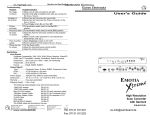
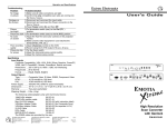
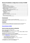
User's Manual
Contents
Introduction to the Emotia Xtreme MX ............................................... Chapter 1
Introduction .......................................................................................... 1-1
About this Manual ......................................................................... 1-1
Features ....................................................................................... 1-2
Specifications ............................................................................... 1-3
Installation and Operation ................................................................... Chapter 2
Installing the Emotia Xtreme MX ......................................................... 2-1
Rack Mounting ............................................................................. 2-1
Cabling ......................................................................................... 2-1
Connecting the Input and Output Cables .............................. 2-1
Front and Rear Panels ................................................................. 2-5
Front Panel ............................................................................ 2-5
Rear Panel ............................................................................ 2-6
Other Reference Material .................................................................. Appendix A
Accessories/Part Numbers ................................................................. A-1
Safety Instructions ...................................................... Inside Front Cover
Limited Warranty ......................................................... Inside Back Cover
Emotia Xtreme MX
User’s Manual
68-302-02
Rev. A
79-05
Page i
Legend of Icons
The following icons may be used in this manual:
___ Important information – for example, an action or a step that must
be done before proceeding.
___ A Warning – possible damage could occur.
_ A Note, a Hint, or a Tip that may be helpful.
__ Possible Electrostatic Discharge (ESD) damage could result from
touching electronic components.
__ Additional information may be referenced in another section, or in
another document.
Extron • Emotia Xtreme MX • User’s Manual
Extron’s Emotia Xtreme MX
User’s Manual
1
Chapter One
Introduction to the Emotia Xtreme MX
Introduction
Features
Specifications
Extron • Emotia Xtreme MX • User’s Manual
Introduction to the Emotia Xtreme MX
Introduction
About This Manual
This manual contains operation, configuration and option
information for the Emotia Xtreme MX Scan Converter.
Emotia Xtreme MX Facts and Features
Extron's EMOTIA ™ XTREME MX converts up to 1600 x 1280
resolution video from Workstation-PC, MAC, SUN, SGI and
more to Composite video (NTSC/PAL), Y/C (S-Video),
Component video and RGBS. It provides a real time, high
resolution output along with professional genlock capabilities,
multi-level anti-flicker, zoom, sizing and positioning capabilities
and 21 preset input memory blocks. With digital signal
processing, the Emotia Xtreme MX also offers a full spectrum of
16 million colors. Its multiscanning capabilities provide
automatic recognition and auto-lock of scan rates between 29 to
92 kHz.
The Emotia Xtreme MX is housed in a rack-mountable metal
enclosure and includes an internal 100-240 volt switch mode
power supply.
An example of an Emotia Xtreme MX application with video
input from a workstation is shown in the diagram below.
Emotia Xtreme MX front and rear panels are shown below.
Page 1-1
Extron • Emotia Xtreme MX • User’s Manual
Introduction to the Emotia Xtreme MX
Features
•
Component Video Output — The Emotia Xtreme MX provides high
quality video output in the Component Video format (R-Y, B-Y, Y)
on BNC connectors.
•
Horizontal/Vertical Sizing and Positioning — These controls allow
centering and sizing of the output image for optium positioning on
the display device. All images displayed through the Emotia Xtreme
MX can be displayed full-screen and without any image cropping
utilizing the sizing and shifting controls.
•
Genlock — Genlock capabilities allow for the integration of the scan
converted images into a professional broadcast environment.
Genlocking provides for seamless, vertical interval switching of
these converted high resolution sources, and other video sources.
Front panel access to horizontal phasing and subcarrier phasing
control is provided for easy adjustment.
•
Multiscanning — The Emotia Xtreme MX automatically recognizes
all signals from 29 kHz to 92 kHz and resolutions from 320 x 200 up
to 1600 x 1280.
•
Outputs — The Emotia Xtreme MX outputs NTSC or PAL video,
Y/C (S-Video), Component Video and RGBS to fulfill any
application and offer compatibility with virtually any output source.
•
Pan/Zoom — The Emotia Xtreme MX has totally variable Horizontal
and Vertical sizing controls that even allow for complete “pan and
scan” around the displayed image up to 200%. With analog control,
adjust the image position and size on screen for maximum usability.
•
Presets — Recall previous settings without having to re-position or
size the image. There are twenty one different presets for sizing
and positioning of all input sources.
•
Six Levels of Anti-Flicker — Although the Emotia Xtreme MX
produces extremely clear output resolution, an anti-flicker switch
has been included to ensure complete satisfaction. There are 6
levels of built in anti-flicker to fit virtually any application specifically
and significantly decrease the flicker that is inherent to interlaced
video allowing for a smooth, clean and stable image output.
Extron • Emotia Xtreme MX • User’s Manual
Page 1-2
Introduction to the Emotia Xtreme MX
Specifications
Input Signals
Computer Compatibility .......... VGA, XGA, SUN, Silicon Graphics,
PowerPC, VESA, NeXT, PowerMAC,
Quadra, PowerBook, Radius and more.
Resolutions ............................. 320 x 200 up to 1600 x 1280
non-interlacing
Frequencies ............................ 29 to 92 kHz
Format ..................................... RGsB, RGBS, RGBHV
Output Signals
Type ........................................ Composite, S-Video, RGBS, Component
NTSC ...................................... 15.75 kHz/60 Hz interlaced, 525 lines
PAL ......................................... 15.63 kHz/50 Hz interlaced, 625 lines
Connectors
Computer Input ....................... 15 HD Male
(MAC & 13W3 adapters supplied*)
Local Monitor .......................... 15 HD Female
(MAC & 13W3 adapters supplied*)
NTSC/PAL .............................. BNC Female
S-VHS ..................................... 4-pin DIN (S-Video) Female
RGBS/Component Video ........ BNC Female x 4
Dimensions ............................... 19.0” W x 11.25” D x 1.74” H
48 cm W x 30 cm D x 4.4 cm H
Shipping Weight ....................... 11.0 lbs
5.0 kg
Power Supply ............................ 100-240 VAC, 50/60 Hz
Internal switch mode
MTBF .......................................... 30,000 Hours
Warranty .................................... Two years, parts &labor
* See Appendix for complete list of supplied adapters.
Page 1-3
Extron • Emotia Xtreme MX • User’s Manual
Extron’s Emotia Xtreme MX
User’s Manual
2
Chapter Two
Installation and Operation
Rack Mounting
Cabling
Front Panel
Rear Panel
Extron • Emotia Xtreme MX • User’s Manual
Installation and Operation
Installing the Emotia Xtreme MX
If rack mounting is required it should be done before cabling,
otherwise, skip to “Cabling” below.
Rack Mounting
To rack mount the Emotia Xtreme MX, mount it as shown below
using 4-user supplied screws to secure the front panel to the
rack. Upon completion of the rack mounting procedure, go to
“Cabling” below.
Cabling
The video output from a workstation connects to the Emotia
Xtreme MX CPU INPUT connector (standard VGA 15-pin HD
Male). An adapter may be required between the workstation and
the VGA cable to the Xtreme MX (see bubble A in the diagram
below). The workstation monitor is connected to the MX
MONITOR OUTPUT connector (standard VGA 15-pin HD
Female). An adapter may be required between the monitor
cable and the MX (see bubble B in the diagram below). The
Emotia Xtreme MX is compatible with most workstations and the
following procedures cover cabling for most applications.
Page 2-1
Extron • Emotia Xtreme MX • User’s Manual
Installation and Operation
VGA PC'S and SUN/SGI (All cables are included)
1. Turn the computer and its monitor Off. For a SUN/SGI
application, connect the provided adapters and . PCs
will not require adapters. Use the diagram below as a guide.
2. Connect the VGA input cable (26-112-15) male end to the
computer or adapter and the female end to the Emotia
Xtreme MX CPU Input connector.
3. Use the computer monitor's cable to connect to the Emotia
Xtreme MX Monitor Output connector or adapter
cable.
4. Connect the cable from the desired Emotia Xtreme MX
output connector (see note below) to the input connector of
the output device.
5. Turn the computer and the computer monitor power On.
6. Use the Emotia Xtreme MX Horizontal centering, Vertical
centering, Horizontal Size and Vertical Size controls to align
the image on the screen.
7. Set the remaining front panel switches as required.
_ Emotia Xtreme MX available outputs are:
1. Composite Video (2 BNC connectors labeled MAIN &
MONITOR, for 1 or 2 monitor(s) or other output devices.)
2. S-Video (4-pin Mini DIN connector)
3. Four BNC connectors switchable to either:
A. RGBS Video B. Component Video (R-Y, B-Y, Y)
Extron • Emotia Xtreme MX • User’s Manual
Page 2-2
Installation and Operation
Installation – Mac Systems (All cables are included)
1. Turn the Mac and its monitor Off. Use the diagram below as
a guide.
2. Connect the Mac/VGA Adapter to the Mac computer configured for desired scan rate. Connect the VGA input
cable
(PN# 26-112-15) from the Mac/VGA Adapter to the
CPU Input on the Emotia Xtreme MX. Connect the Mac
monitor cable to the adapter and connect the adapter to
the Monitor Output on the Emotia Xtreme MX.
4. Connect the cable from the desired Emotia Xtreme MX
output connector (see note below) to the input connector of
the output device.
5. Turn the computer and the computer monitor power On.
6. Use the Emotia Xtreme MX Horizontal centering, Vertical
centering, Horizontal Size and Vertical Size controls to align
the image on the screen.
7. Set the remaining front panel switches as required.
_ Emotia Xtreme MX available outputs are:
1. Composite Video (2 BNC connectors labeled MAIN &
MONITOR, for 1 or 2 monitor(s) or other output devices.)
2. S-Video (4-pin Mini DIN connector)
3. Four BNC connectors switchable to either:
A. RGBS Video B. Component Video (R-Y, B-Y, Y)
Page 2-3
Extron • Emotia Xtreme MX • User’s Manual
Installation and Operation
Genlock
The Genlock IN and OUT BNC
connectors on the rear panel of the
Emotia Xtreme MX provide a way to
synchronize the output video with an
incoming Genlock signal. The IN
BNC connector receives the external
Rear Panel GENLOCK
Genlock timing signal, the OUT BNC
BNC connectors and
connector allows the signal to be
Termination switch.
passed on to another video device if
required. The termination switch
(located between the In and Out BNC
connectors) enables termination of
the Genlock signal at 75 ohms if no
other termination is available. Front
panel controls labeled GENLOCK
Front panel
enable fine adjustment of the
GENLOCK controls.
synchronized video.
An Emotia Xtreme MX using a Burst generator as the source for
a Genlock signal is shown in the diagram below. The GENLOCK
signal passes through the Xtreme MX GENLOCK OUT BNC
connector and on to another device (Video Camera).
See Emotia Xtreme MX Front Panel and Rear Panel on Pages
2-5 and 2-6 for operating information.
Extron • Emotia Xtreme MX • User’s Manual
Page 2-4
Page 2-5
Installation and Operation
Extron • Emotia Xtreme MX • User’s Manual
Emotia Xtreme MX Front Panel
A. Freeze Button and LED – Press the Freeze Button once to freeze the display on a frame, press it again to release the
display. The LED is ON in Freeze Frame mode.
B. Power On LED – This LED is ON if power is applied to the unit.
C. Anti Flicker – Six levels of anti-flicker are built in. Set switches for minimum flicker. For example, for highest amount of
flicker reduction the anti-flicker switches would be set in the “+” and “3” positions.
D. NTSC/PAL– This switch selects the video standard to be used, NTSC or PAL.
E. Genlock Controls – If using Genlock, the two switches combine to make a coarse phase setting between the video output
signal and the Genlock signal. These switch settings provide for 0º (in phase), or delayed by 90º, 180º, or 270º (both
switches down) after the Genlock signal. The SCØ control is used to "fine-tune" this phase between Genlock sub-carrier
(color burst) and the output video. The HØ control is used to adjust the phase between the Genlock Sync and the Output
Video Sync. The GENLOCK LED will illuminate when an active reference signal is applied.
F. Memory – Store up to 21 sizing and positioning settings for later recall. To save a setting in memory, press and hold the
STORE button until the STORE LED flashes ON then OFF. Memory settings are recalled automatically when a video signal is
applied with a scan rate matching one for which settings were previously stored. To reset an altered memory setting to the
previously stored position, toggle the NTSC/PAL switch (D). This is only available if the altered settings have not been stored.
G. IMAGE/ZOOM – STD = Underscan, OVER = Overscan, ZOOM = Zoom. With switch in the ZOOM position, use the sizing
controls to adjust magnification up to 200%. H CTR and V CTR controls allow movement within the magnified image.
Horizontal Centering Control – Moves the picture to the left or right on the display screen.
Vertical Centering Control – Moves the position of the picture up or down on the screen.
Horizontal Size Control – This adjusts the width of the picture.
Vertical Size Control – This adjusts the height of the picture.
H. AC Power Connector – Standard IEC type. 100-240 VAC, 50/60 Hz, Internal switch mode
J. GENLOCK IN Connector – BNC connector for Genlock input.
K. GENLOCK HI-Z/75Ω
Ω – Pushbutton selects termination, If there is no other Genlock termination, set the switch to 75Ω.
L. GENLOCK OUT Connector – BNC connector for Genlock out to next device (if any).
M. MONITOR OUTPUT – Female 15-pin VGA style connector.
N. HI-Z/75W Switch – HI-Z = output monitor connected, 75Ω position = no output monitor.
O. CPU INPUT – Male 15-pin VGA style connector.
P. NTSC/PAL MAIN BNC Connector – Composite Video Output number 1.
Q. NTSC/PAL MONITOR BNC Connector – Composite Video Output number 2.
R. S-Video Connector – S-Video output for S-VHS, Hi8 or other devices accepting this video format.
Page 2-6
S. R-Y/B-Y/Y / RGBS Pushbutton – Selects R-Y/B-Y/Y (Component video) or RGBS video for BNC output connectors.
T. COMPONENT/RGBS Output – Four BNC connectors for Component or RGBS output video.
Installation and Operation
Extron • Emotia Xtreme MX • User’s Manual
Emotia Xtreme MX Rear Panel
Installation and Operation
NOTES:
Page 2-7
Extron’s Emotia Xtreme MX
User’s Manual
A
Appendix A
Other Reference Material
Accessories and Part Numbers
Limited Warranty
Other Reference Material
Accessories/Part Numbers
BNC-4 HR Cable
BNC-4-3’HR (3 feet/0.9 meters) ......................................................... 26-210-01
BNC-4-6’HR (6 feet/1.8 meters) ......................................................... 26-210-02
BNC-4-12’HR (12 feet/3.6 meters) ..................................................... 26-210-03
BNC-4-25’HR (25 feet/7.5 meters) ..................................................... 26-210-04
BNC-4-50’HR (50 feet/15.0 meters) ................................................... 26-210-05
BNC-4-75’HR (75 feet23.0 meters) .................................................... 26-210-06
BNC-4-100’HR (100 feet/30.0 meters) ............................................... 26-210-07
BNC-4-150’HR (150 feet/45.0 meters) ............................................... 26-210-08
BNC-4-200’HR (200 feet/60.0 meters) ............................................... 26-210-09
BNC-4-250’HR (250 feet/75.0 meters) ............................................... 26-210-54
BNC-4-300’HR (300 feet/90.0 meters) ............................................... 26-210-53
BNC-4 Mini-HR Bulk (300’/90m up to 5000’/1500m) ........................ 22-073-01
VGA extension cables
VGA 3’ HR (3 feet/0.9 meters) ............................................................ 26-112-17
VGA 6’ HR (6 feet/1.8 meters) ............................................................ 26-112-15
VGA 15’ HR (15 feet/4.5 meters) ....................................................... 26-112-01
VGA 25’ HR (25 feet/7.5 meters) ....................................................... 26-112-05
VGA 50’ HR (50 feet/15.0 meters) ..................................................... 26-112-02
VGA 75’ HR (75 feet/23.0 meters) ..................................................... 26-112-03
VGA 100’ HR (100 feet/30.0 meters) ................................................. 26-112-04
VGA 150’ HR (150 feet/45.7 meters) ................................................. 26-112-09
VGA 200’ HR (200 feet/60.0 meters) ................................................. 26-112-08
VGA 250’ HR (250 feet/76.2 meters) ................................................. 26-112-16
RCA-6’ - RCA Male to Male, 6 feet/1.8 meters ................................. 26-345-01
S-VHS-6’ - Male to Male S-Video Cable, 6 feet/1.8 meters ............. 26-316-02
S-VHSM20’ - Male to Male S-Video Cable, 20 feet/6 meters ........... 26-316-01
S-VHS BNC - Male to Male S-Video to BNC Cable Adapter ............ 26-353-01
Emotia Xtreme MX ............................................................................... 60-225-01
Accessories supplied with the Emotia Xtreme MX:
13W3/VGA adapter .............................................................................. 26-372-01
13W3/VGA monitor cable, 1’ (0.3 m) ................................................. 26-371-01
Mac/VGA adapter ................................................................................ 26-374-05
Mac/VGA monitor cable, 1’ (0.3 m) .................................................... 26-340-01
Mac HV/VGA monitor cable, 1’ (0.3 m) .............................................. 26-340-02
S-Video cable, 6’ (1.8 m) .................................................................... 26-316-02
RCA cable, 6’ (1.8 m) .......................................................................... 26-345-01
VGA 6’ HR ............................................................................................ 26-112-15
BNC/M-RCA/F adapter ........................................................................ 10-264-01
Page A-1
Extron • Emotia Xtreme MX • User’s Manual
Extron Electronics
1230 South Lewis Street
Anaheim, CA 92805
(714) 491-1500 FAX (714) 491-1517
U.S.A.
Extron Electronics, Europe
Beeldschermweg 6C
3821 AH Amersfoort
+31-33-453-4040 FAX +31-33-453-4050
The Netherlands
Extron • Emotia Xtreme MX • User’s Manual
Extron Electronics, Asia
41B Kreta Ayer Road
Singapore 089003
+65-226-0015 FAX +65-226-0019
Singapore