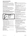
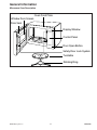
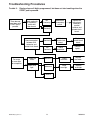
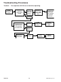
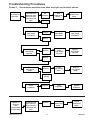
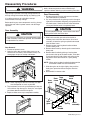
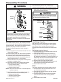
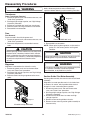
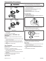
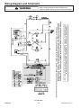
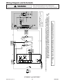
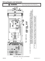
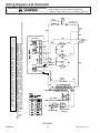
1
Service
This manual is to be used by qualified appliance
technicians only. Maytag does not assume any
responsibility for property damage or personal
injury for improper service procedures done by an
unqualified person.
2001-2003
Countertop
Domestic
Microwave Ovens
This Base Manual covers general information
©2005 Maytag Services
This manual includes, but is
not limited to the following:
ACM0720AB
ACM0720AW
ACM0860AB
ACM0860AC
ACM0860AS
ACM0860AW
ACM1120AB
ACM1120AS
ACM1120AW
ACM1420AB
ACM1420AW
ACM1460AB
ACM1460AC
ACM1460AW
ACM2160AB
ACM2160AC
ACM2160AS
ACM2160AW
MMC5086AAB
MMC5086AAQ
MMC5086AAS
MMC5086AAW
UMC1061AAB
UMC1061AAW
16026268
Replaces 16021670
June 2005
Important Information
Pride and workmanship go into every product to provide our customers with quality products. It is possible, however,
that during its lifetime a product may require service. Products should be serviced only by a qualified service
technician who is familiar with the safety procedures required in the repair and who is equipped with the proper tools,
parts, testing instruments and the appropriate service manual. REVIEW ALL SERVICE INFORMATION IN THE
APPROPRIATE SERVICE MANUAL BEFORE BEGINNING REPAIRS.
Important Notices for Consumers and Servicers
!
WARNING
To avoid risk of serious injury or death, repairs should not be attempted by an unauthorized personal, dangerous
conditions (such as exposure to electrical shock) may result.
!
CAUTION
Maytag will not be responsible for any injury or property damage from improper service procedures. If performing
service on your own product, assume responsibility for any personal injury or property damage which may result.
To locate an authorized servicer, please consult your telephone book or the dealer from whom you purchased this
product. For further assistance, please contact:
Customer Service Support Center
CAIR Center
Web Site
Telephone Number
WWW.AMANA.COM ................................................ 1-800-843-0304
WWW.JENNAIR.COM ............................................. 1-800-536-6247
WWW.MAYTAG.COM ............................................. 1-800-688-9900
CAIR Center in Canada ........................................... 1-800-688-2002
Amana Canada Product ........................................... 1-866-587-2002
Recognize Safety Symbols, Words, and Labels
! DANGER
DANGER—Immediate hazards which WILL result in severe personal injury or death.
!
WARNING
WARNING—Hazards or unsafe practices which COULD result in severe personal injury or death.
!
CAUTION
CAUTION—Hazards or unsafe practices which COULD result in minor personal injury or product or property
damage.
16026268
2
©2005 Maytag Services
Table of Contents
Disassembly Procedures
Door Assembly ......................................................... 22
Door Disassembly .................................................... 22
Outer Case ............................................................... 23
Control Panel ............................................................ 23
P.C. Board ................................................................ 23
Control Key Panel ..................................................... 24
Interlock Door Latch Switches .................................. 24
High Voltage Capacitor ............................................. 25
Diode ........................................................................ 25
Transformer .............................................................. 26
Fuse ......................................................................... 26
Magnetron ................................................................ 26
Suction Guide / Fan Motor Assembly ....................... 26
Humidity Sensor–ACM1460A* and ACM2160A* ....... 27
Oven Thermostat ...................................................... 27
Light Socket ............................................................. 27
Turntable Motor ........................................................ 27
Noise Filter .............................................................. 27
Wiring Diagrams And Schematics .............................. 28
Appendix A
Installation Instructions .......................................... A-2
Appendix B
Programming Instructions for
ACM0720A* and ACM1061A* .............................. B-2
Programming Instructions for
ACM1120A* and ACM1420A* ............................. B-4
Programming Instructions for
ACM1460A* and ACM2160A* .............................. B-7
Programming Instructions for
ACM0860A* and MMC5086A* .......................... B-10
Appendix C
Cleaning Instructions .............................................. C-2
Important Information ................................................... 2
Important Product Information ...................................... 4
Important Safety Information ........................................ 5
Microwave Leakage Testing ......................................... 6
Specification Information .............................................. 7
General Information
Placement of the Oven ............................................. 9
Location of Model Number ........................................ 9
Model Identification ................................................... 9
Service ....................................................................... 9
Parts and Accessories .............................................. 9
Extended Service Plan .............................................. 9
Radio Interference ..................................................... 9
Electrical Requirements ........................................... 10
Cleaning .................................................................. 10
Grounding Instructions ............................................ 10
Microwave Oven Description .................................... 11
Testing Procedures
Primary Interlock Switch Test ................................... 12
Secondary Interlock Switch Test ............................... 12
Interlock Monitor Switch Test .................................... 12
Magnetron ................................................................ 12
High Voltage Diode ................................................... 13
High Voltage Transformer .......................................... 13
Fan Motor ................................................................. 13
Turntable Motor ......................................................... 13
High Voltage Capacitor ............................................. 13
Humidity Sensor ....................................................... 13
Relay ........................................................................ 14
Oven Thermostat ...................................................... 14
Fuse ......................................................................... 14
Control Key Panel ..................................................... 15
Troubleshooting Procedures ........................................ 16
©2005 Maytag Services
3
16026268
3
Important Product Information
!
!
WARNING
WARNING
To avoid risk of electrical shock, injury, or death, make
sure these grounding instructions are followed.
Precautions to be observed before and during
servicing to avoid possible exposure to excessive
microwave energy, or electrical shock disconnect
power to oven.
Grounding Instructions
(A) Do not operate or allow oven to be operated with
door open.
!
(B) Make the following safety checks on all ovens to
be serviced before activating the magnetron or
other microwave source, and make repairs as
necessary:
WARNING
Do not remove grounding prong when installing
grounded appliance in a home or business that does
not have three wire grounding receptacle, under no
condition is grounding prong to be cut off or removed.
It is the personal responsibility of the consumer to
contact a qualified electrician and have properly
grounded three prong wall receptacle installed in
accordance with appropriate electrical codes
• Interlock operation
• Proper door closing
• Seal and sealing surfaces (arcing, wear, and
other damage)
• Damage to or loosening of hinges and latches
• Evidence of dropping or abuse
(C) Before turning on microwave power for any
service test or inspection within the microwave
generating compartments, check the magnetron,
waveguide or transmission line, and cavity for
proper alignment, integrity, and connections.
Should a two prong adapter plug be required
temporarily, it is the personal responsibility of the
consumer to have it replaced with properly grounded
three prong receptacle or the two prong adapter properly
grounded by a qualified electrician in accordance with
appropriate electrical codes.
(D) Any failed or misadjusted components in the
interlock, monitor, door seal, and microwave
generation and transmission systems shall be
repaired, replaced or adjusted by procedures
described in this manual before oven is released to
the consumer.
Servicing of Grounded Products
The standard accepted color coding for grounding wires
is GREEN or GREEN WITH YELLOW STRIPE. These
ground leads are NOT to be used as current carrying
conductors. It is extremely important that the technician
replace any and all grounds prior to completion of the
service call. Under no condition should ground wire be
left off causing a potential hazard to technicians and
consumer.
(E) Check microwave leakage to verify compliance with
the federal performance standard should be
performed on each oven prior to release to the
consumer.
Wiring
Good service practice is to never route wiring over
terminals and/or sharp edges. This applies to any
wiring without regard to the circuit voltage. Wire
insulation material and thickness is designed and
regulated for electrical spacing purpose only, but
cannot always be relied upon because of possible cuts
and/or abrasions, which can occur during servicing.
16026268
4
©2005 Maytag Services
Important Safety Information
!
CAUTION
Read the following information to avoid possible exposure to microwave radiation:
7. In the area of the transformer, capacitor, diode, and
magnetron there is HIGH VOLTAGE. When the unit is
operating, keep this area clean and free of anything
which could possibly cause an arc or ground, etc.
8. Do not for any reason defeat the interlock switches.
There is no valid reason for this action at any time;
nor will it be condoned by Maytag.
9. IMPORTANT: Before returning a microwave to a
customer, check for proper switch interlock action.
The primary and secondary switches MUST open
when the door is actuated. The monitor switch MUST
close at a 1/4 inch when the door is opened.
10.Before returning a microwave to a customer, verify
the door spacing is reasonably uniform along the
top, bottom, and sides, and that it measures 1/8 inch
or less.
11. The microwave oven should never be operated with:
• Any components removed and/or bypassed.
• Any of the safety interlocks failing.
• Any of the seal surfaces failing, missing, or
damaged.
12.To ensure that the unit does not emit excessive
microwave leakage and to meet the Department of
Health Human Service guidelines, check the oven
for microwave leakage using Narda Model 8100,
8200, Holaday HI1500, HI1501 or Simpson 380M
leakage monitor as outlined in the instructions. The
maximum leakage level allowed is 4mW/cm2.
13. If servicer encounters an emission reading over
4 mW/cm2, the servicer is to cease repair and
contact the Maytag Service Department immediately
for further direction. Maytag will contact the proper
Government Agency upon verification of the test
results.
The basic design of the Maytag and Amana microwave
oven makes it an inherently safe device to both use and
service. However, there are some precautions which
should be followed when servicing the microwave oven to
maintain this safety. These are as follows:
1. Always operate the unit from an adequately grounded
outlet. Do not operate on a two-wire extension cord.
2. Before servicing the unit (if unit is operable), perform
the microwave leakage test.
3. The oven should never be operated if the door does
not fit properly against the seal, the hinges or hinge
bearings are damaged or broken; the choke is
damaged, (pieces missing, etc.); or any other visible
damage can be noted. Check the choke area to
ensure that this area is clean and free of all foreign
matter.
4. If the oven operates with the door open and
produces microwave energy, take the following
steps.
A. Tell the user not to operate the oven.
B. Contact Maytag immediately.
5. Always have the oven disconnected when the outer
case is removed except when making the "live" tests
called for in the Service Manual. Do not reach into the
equipment area while the unit is energized. Make all
connections for the test and check them for tightness
before plugging the cord into the outlet.
6. Always ground the capacitors on the magnetron filter
box and H. V. Capacitor with an insulated-handle
screwdriver before working in the high voltage area
of the equipment compartment. Some types of
failures will leave a charge in these capacitors and
the discharge could cause a reflex action which
could make you injure yourself.
©2005 Maytag Services
5
16026268
Microwave Leakage Testing
!
Measurement With the Outer Panel
Removed
WARNING
Check for radiation leakage after servicing. Should the
leakage be more than 4mW/cm2 inform Maytag
immediately. After repairing or replacing any radiation
safety device, keep a written record for future
reference, as required by D.H.H.S. and HEW
regulations. This requirement must be strictly
observed. In addition, the leakage reading must be
recorded on the service repair ticket while in the
customer’s home.
!
DANGER
Avoid contacting any high voltage components.
Whenever you replace the magnetron, measure for
radiation leakage before the outer panel is installed and
after all necessary components are replaced or
adjusted. Special care should be taken in measuring
around the magnetron.
Equipment
Measurement With a Fully Assembled Oven
• Electromagnetic radiation monitor
• 600 cc glass beaker
After all components including the outer panel are fully
assembled, measure for radiation leakage around the
door periphery, the door viewing window, the exhaust
opening, and air inlet openings.
Procedure For Measuring Radiation
Leakage
Note before measuring • Do not exceed meter full scale deflection. Leak
monitor should initially be set to the highest scale.
• To prevent false readings the test probe should be
held by the grip portion of the handle only.
• The scan speed is equal to one inch per antenna
revolution or one inch per second if antenna speed is
unknown.
• Areas to be checked are all door seal areas and any
venting parts.
• Leakage with the outer panel removed...4mW/cm2 or
less.
• Leakage for fully assembled oven with door normally
closed ...4mW/cm2 or less.
• Leakage for a fully assembly oven (before the latch
switch (primary) is interrupted) while pulling the door ...
4mW/cm2 or less.
1 . Pour 275 ±15 cc (9 oz ±1/2 oz) of 20 ± 5°C
(68 ± 9°F) water in a beaker which is graduated to
600 cc and place the beaker in the center of oven.
2. Set the radiation monitor to 2450 MHz and use it
following the manufacturer’s recommended test
procedure to assure correct results.
3. While measuring the leakage, always use the two
inch (5 cm) spacer supplied with the probe.
4. Press the start pad or turn on the timer and with the
magnetron oscillating, measure the leakage by
holding the probe perpendicular to the surface being
measured.
16026268
6
Record Keeping and Notification After
Measurement
1. After any adjustment or repair to a microwave oven,
a leakage reading must be taken. Record this
leakage reading on the repair ticket even if it is zero.
2. A copy of the repair ticket and the microwave
leakage reading should be kept by the repair facility.
©2005 Maytag Services
Specification Information
Item
Model
Power Requirement
Power Output
Microwave Frequency
Timer
Outside Dimensions
Description
ACM1420A*
ACM1460A*
ACM2160A*
120 Volts AC 60 Hz 1,500 Watts (13A) Single phase, 3 wire grounded
1100 Watts full microwave power (IEC705)
2,450 MHz
0 ~ 99 min. 99 sec.
21 7/8” (W)
21 7/8” (W)
23 7/8” (W)
x 17 1/4” (H)
x 17 1/4” (H)
x 19 13/16” (H)
x 12 5/8” (D)
x 12 5/8” (D)
x 13 9/16” (D)
Cavity Dimensions
14 3/4” (W)
14 13/16” (W)
17 17/32” (W)
x 15 15/16” (H)
x 15 15/16” (H)
x 18 21/32” (H)
x 9 7/8” (D)
x 9 7/8” (D)
x 10 7/8” (D)
Net Weight
37 lbs. (approx.)
37 lbs. (approx.)
42 lbs. (approx.)
Shipping Weight
40 lbs. (approx.)
40 lbs. (approx.)
46 lbs. (approx.)
Control Complement
Touch Control System
Clock: 1:00 - 12:59
Microwave Power for Variable Cooking
Power Level
HIGH ---------------------------------------------------------Full power throughout the cooking time
9 (Sauté) ------- approx. 90% of Full power, 8 (Reheat) ----------- approx. 80%
7 (Med.-High) ------------------- approx. 70%, 6 (Medium) ---------- approx. 60%
5 (Med.-Low) -------------------- approx. 50%, 4 (Defrost) ----------- approx. 40%
3 (Low) ---------------------------- approx. 30%, 2 (Simmer) ---------- approx. 20%
1 (Warm) ------------------------ approx. 10%
Nameplate Location
Front
Accessories
Owner’s manual & cooking guide
Glass Turntable
Rotating Ring
This microwave oven is designed for household use only.
It is not recommended for commercial purposes.
Item
Model
Power Requirement
Power Output
Microwave Frequency
Timer
Outside Dimensions
Cavity Dimensions
Net Weight
Shipping Weight
Control Complement
Description
UMC1061AA*
120 Volts AC 60 Hz 1,000 Watts (8.5 A) Single phase, 3 wire grounded
700 Watts full microwave power (IEC705)
2,450 MHz
0 ~ 99 min. 99 sec.
17 15/16” (W) x 11 3/16” (H) x 12 5/8” (D)
12 3/16” (W) x 7 31/32” (H) x 11 5/8” (D)
25 lbs. (approx.)
27 lbs. (approx.)
Touch Control System
Clock: 1:00 - 12:59
Microwave Power for Variable Cooking
Power Level
HIGH ---------------------------------------------------------Full power throughout the cooking time
9 (Sauté) ------- approx. 90% of Full power, 8 (Reheat) ----------- approx. 80%
7 (Med.-High) ------------------- approx. 70%, 6 (Medium) ---------- approx. 60%
5 (Med.-Low) -------------------- approx. 50%, 4 (Defrost) ----------- approx. 40%
3 (Low) ---------------------------- approx. 30%, 2 (Simmer) ---------- approx. 20%
1 (Warm) ------------------------ approx. 10%
Nameplate Location
Front
Accessories
Owner’s manual & cooking guide
Glass Turntable
Rotating Ring
This microwave oven is designed for household use only.
It is not recommended for commercial purposes.
©2005 Maytag Services
7
16026268
Specification Information
Item
Model
Power Requirement
Power Output
Microwave Frequency
Timer
Outside Dimensions
Cavity Dimensions
Net Weight
Shipping Weight
Control Complement
Nameplate Location
Description
ACM0720A*
ACM1120A*
120 Volts AC 60 Hz
120 Volts AC 60 Hz
1,050 Watts (9.3A)
1,500 Watts (13A)
Single phase, 3 wire grounded
Single phase, 3 wire grounded
700 Watts full microwave power (IEC705) 1100 Watts full microwave power (IEC705)
2,450 MHz
0 ~ 99 min. 99 sec.
19” (W) x 11” (H) x 12 7/8” (D)
20 7/8” (W) x 12 3/8” (H) x 15 1/2” (D)
12 1/4” (W) x 7 3/4” (H) x 12 1/2” (D)
13 3/4” (W) x 8 3/4” (H) x 14 5/8” (D)
25 lbs. (approx.)
35 lbs. (approx.)
27 lbs. (approx.)
39 lbs. (approx.)
Touch Control System
Clock: 1:00 - 12:59
Microwave Power for Variable Cooking
Power Level
HIGH ---------------------------------------------------------Full power throughout the cooking time
9 (Sauté) ------- approx. 90% of Full power, 8 (Reheat) ----------- approx. 80%
7 (Med.-High) ------------------- approx. 70%, 6 (Medium) ---------- approx. 60%
5 (Med.-Low) -------------------- approx. 50%, 4 (Defrost) ----------- approx. 40%
3 (Low) ---------------------------- approx. 30%, 2 (Simmer) ---------- approx. 20%
1 (Warm) ------------------------ approx. 10%
Front
Accessories
Owner’s manual & cooking guide
Glass Turntable
Rotating Ring
This microwave oven is designed for household use only.
It is not recommended for commercial purposes.
Item
Model
Power Requirement
Power Output
Microwave Frequency
Timer
Outside Dimensions
Cavity Dimensions
Net Weight
Shipping Weight
Control Complement
Nameplate Location
Description
ACM0860A*
MMC5086AA*
120 Volts AC 60 Hz
1,200 Watts (10.5 A)
Single phase, 3 wire grounded
800 Watts full microwave power (IEC705)
2,450 MHz
0 ~ 99 min. 99 sec.
19” (W) x 11” (H) x 12 7/8” (D)
12 1/4” (W) x 7 3/4” (H) x 12 1/2” (D)
25 lbs. (approx.)
27 lbs. (approx.)
Touch Control System
Clock: 1:00 - 12:59
Microwave Power for Variable Cooking
Power Level
HIGH ---------------------------------------------------------Full power throughout the cooking time
9 (Sauté) ------- approx. 90% of Full power, 8 (Reheat) ----------- approx. 80%
7 (Med.-High) ------------------- approx. 70%, 6 (Medium) ---------- approx. 60%
5 (Med.-Low) -------------------- approx. 50%, 4 (Defrost) ----------- approx. 40%
3 (Low) ---------------------------- approx. 30%, 2 (Simmer) ---------- approx. 20%
1 (Warm) ------------------------ approx. 10%
Front
Accessories
Owner’s manual & cooking guide
Glass Turntable
Rotating Ring
This microwave oven is designed for household use only.
It is not recommended for commercial purposes.
16026268
8
©2005 Maytag Services
General Information
Placement of the Oven
Service
This microwave can be easily placed in the kitchen,
family room, or anywhere else in the house. Place the
oven on a flat surface such as a kitchen countertop or a
specially designed microwave oven cart. Do not place
oven above a gas or electric range. Free air flow around
the oven is important.
Keep a copy of sales receipt for future reference or in
case warranty service is required. To locate an authorized
servicer:
• For Amana product call 1-800-628-5782 or visit the
Web Site at www.amana.com
• For Maytag/Jenn-Air product call 1-800-462-9824 or
visit the Web Site at www.maytag.com or
www.jennair.com
• For product in Canada call 1-866-587-2002 or visit the
Web Sites at www.amana.com or www.maytag.com or
www.jennair.com
Warranty service must be performed by an authorized
servicer. We also recommend contacting an authorized
servicer, if service is required after warranty expires.
Do Not Block Air Vents
All air vents must be kept clear during cooking. If air
vents are covered during operation the oven may
overheat. In this case, a sensitive thermal safety device
automatically turns the oven off. The oven will be
inoperable until the oven has cooled sufficiently.
Location of Model Number
To request service information or replacement parts, the
service center will require the complete model, serial, and
manufacturing number of your microwave oven. The
number is located on the oven front as shown in the
illustration below.
Parts and Accessories
Purchase replacement parts and accessories over the
phone. To order accessories for your product call:
• For Amana product call 1-877-232-6771 or visit the
Web Site at www.amana.com
• For Maytag/Jenn-Air product call 1-800-462-9824 or
visit the Web Site at www.maytag.com or
www.jennair.com
• For product in Canada call 1-866-587-2002 or visit the
Web Sites at www.amana.com or www.maytag.com or
www.jennair.com
Cavity
Front
Extended Service Plan
We offer long-term service protection for this new oven.
Model Identification
• Asure™ Extended Service Plan is specially designed
to supplement Amana’s strong warranty. This plan
covers parts, labor, and travel charges.
Call 1-866-232-6244 for information.
• Dependability PlusSM Extended Service Plan is
specially designed to supplement Maytag’s and
Jenn-Air’s strong warranty. This plan covers parts,
labor, and travel charges.
Call 1-800-925-2020 for information.
Complete enclosed registration card and promptly return.
If registration card is missing:
• For Amana product call 1-800-843-0304 or visit the
Web Site at www.amana.com
• For Maytag product call 1-800-688-9900 or visit the
Web Site at www.maytag.com
• For Jenn-Air product call 1-800-536-6247 or visit the
Web Site at www.jennair.com
• For product in Canada call 1-866-587-2002 or visit the
Web Sites at www.amana.com or www.maytag.com or
www.jennair.com
When contacting provide product information located on
rating plate. Record the following:
Model Number:
Manufacturing Number:
Serial or S/N Number:
Date of purchase:
Dealer’s name and address:
©2005 Maytag Services
Radio Interference
1. Microwave oven operation may interfere with the radio
or TV reception.
2. When there is interference, it may be reduced or
eliminated by taking the following measures:
• Clean the door and the seal surface of the oven.
• Re-orient the receiving antenna of the radio or TV.
• Relocate the microwave oven in relation to the radio
or TV.
• Move the microwave away from the receiver.
• Plug the microwave into a different outlet so that
the microwave and receiver are on different branch
circuits.
___________________
___________________
___________________
___________________
___________________
9
16026268
General Information
Electrical Requirements
Grounding Instructions
The oven is designed to operate on a Standard
120 VAC, 60 Hz household outlet. Be sure the circuit is
at least 15 or 20 A and the microwave oven is the only
appliance on the circuit. It is not designed for 50 Hz or
any circuit other than a 120 VAC, 60 Hz circuit.
This appliance must be grounded. If an electrical short
circuit occurs, grounding reduces the risk of electric
shock by providing an escape wire for the electric
current. The cord for this appliance has a grounding wire
with a grounding plug. Put the plug into an outlet that is
properly installed and grounded.
· Electrical Rating of the Oven: 120 VAC, 60 Hz
!
Cleaning
WARNING
To avoid risk of electric shock, personal injury or death,
use grounding plug properly.
Before cleaning the oven, unplug the power supply cord.
If impossible, open the oven door to prevent an accidental
oven start.
Ask a qualified electrician if you do not understand the
grounding instructions or if you wonder whether the
appliance is properly grounded.
Inside of the Oven
Use a damp cloth to wipe out crumbs and spillovers. It is
important to keep the area between door and cavity front
clean to assure a tight seal. Remove greasy spatters
with a sudsy cloth, then rinse and dry. Do not use harsh
detergent or abrasive cleaners.
Keep the electrical power cord dry and do not pinch or
crush it in any way.
Properly Polarized and
Grounded Outlet
Glass Tray
The glass tray can be washed by hand or in the
dishwasher.
Control Panel
Wipe with a damp cloth followed immediately by a dry
cloth. The Child Lock feature is also useful when
cleaning the control panel. Child Lock prevents
accidental programming when wiping the control panel
(if so equipped).
Three-Pronged (Grounding) Plug
For a permanently connected appliance: This appliance
must be connected to a grounded, metallic, permanent
wiring system, or an equipment grounding conductor
should be run with the circuit conductors and connected
to the equipment grounding terminal or lead on the
appliance.
Door
If steam accumulates inside or around the outside of the
oven door, wipe the panel with a soft cloth. This may
occur when the microwave oven is operated under high
humidity conditions and in no way indicates a
malfunction of the unit.
Outside Oven Surface
Clean with damp cloth. To prevent damage to the
operating parts inside the oven, the water should not be
allowed to seep into the ventilation openings.
After cleaning the oven, be sure that the rotating ring
and the glass tray are in the right position. Press the
STOP/ CLEAR pad twice to reset any accidental key
setting.
16026268
10
©2005 Maytag Services
General Information
Microwave Oven Description
Oven Front Plate
Window Door Screen
Door Seal
Display Window
Control Panel
Door Open Button
Safety Door Lock System
Turntable
Rotating Ring
©2005 Maytag Services
11
16026268
Testing Procedures
! WARNING
Disconnect power before performing the following
procedures unless testing requires power.
NOTES:
• Perform microwave energy leakage test if unit is
serviced for any reason.
• Verify wire leads are connected to correct positions.
• When removing wire terminal plugs from connectors,
grasp the connector, not the wires.
NOTE: When replacing component use identical
replacement part.
Primary Interlock Switch Test
Interlock Monitor Switch Test
NOTE: After repairing the door or the interlock system,
it is necessary to do a continuity test before
operating the oven.
When the door is opened slowly, an audible click should
be heard. If the latch does not activate the switch when
the door is closed, the switch should be adjusted in
accordance with the adjustment procedure.
When the door is opened slowly, an audible click should
be heard. If the latch does not activate the switch when
the door is closed, the switch should be adjusted in
accordance with the adjustment procedure.
1. Disconnect power to oven and remove outer case,
(see “Outer Case” section in Disassembly
Procedure).
2. Remove control panel, (see “Control Panel” section
in Disassembly Procedure).
3. Discharge high voltage capacitor, (see "High Voltage
Capacitor" section in Disassembly Procedure).
4. Disconnect wire leads from switch.
5. Perform a continuity test by connecting one meter
lead on COM terminal and the other meter lead on
NO terminal.
Readings should be as follows:
Door closed ................. 0 ohms
Door opened ............... Infinite ohms
1. Disconnect power to oven and remove outer case,
(see “Outer Case” section in Disassembly
Procedure).
2. Remove control panel, (see “Control Panel” section
in Disassembly Procedure).
3. Discharge high voltage capacitor, (see "High Voltage
Capacitor" section in Disassembly Procedure).
4. Disconnect wire leads from switch.
5. Perform a continuity test by connecting one meter
lead on COM terminal and the other meter lead on
NC terminal.
Readings should be as follows:
Door closed ................. Infinite ohms
Door opened ...............0 ohms
NOTE: When replacing component use identical
replacement part.
NOTE: When replacing component use identical
replacement part.
NOTE: After repairing the door or the interlock system,
it is necessary to do a continuity test before
operating the oven.
NOTE: After repairing the door or the interlock system,
it is necessary to do a continuity test before
operating the oven.
Secondary Interlock Switch Test
Magnetron
When the door is opened slowly, an audible click should
be heard. If the latch does not activate the switch when
the door is closed, the switch should be adjusted in
accordance with the adjustment procedure.
1. Disconnect power to oven and remove outer case,
(see “Outer Case” section in Disassembly
Procedure).
2. Remove control panel, (see “Control Panel” section
in Disassembly Procedure).
3. Discharge high voltage capacitor, (see "High Voltage
Capacitor" section in Disassembly Procedure).
4. Disconnect wire leads from switch.
5. Perform a continuity test by connecting one meter
lead on COM terminal and the other meter lead on
NO terminal.
Readings should be as follows:
Door closed ................. 0 ohms
Door opened ............... Infinite ohms
16026268
1. Disconnect power to oven and remove outer case,
(see “Outer Case” section in Disassembly
Procedure).
2. Discharge high voltage capacitor, (see "High Voltage
Capacitor" section in Disassembly Procedure).
3. Disconnect wire leads to magnetron.
4. Measure the resistance across filament terminals of
the magnetron.
Reading should be less than 1 ohm.
5. Measure the resistance from each filament terminal
to ground. Reading should indicate infinite ohms.
NOTE: Any other readings then what should be
indicated, magnetron needs to be replaced.
NOTE: Replace the magnetron if magnetron indications
are OK and all other high voltage components
test good (but the unit does not sufficiently heat).
12
©2005 Maytag Services
Testing Procedures
! WARNING
High Voltage Diode
1. Disconnect power to oven and remove outer case,
(see “Outer Case” section in Disassembly
Procedure).
2. Discharge high voltage capacitor, (see "High Voltage
Capacitor" section in Disassembly Procedure).
3. Disconnect wire leads to high voltage diode.
4. Measure resistance of diode with meter leads.
Reverse meter leads and measure again. Normal
reading would be continuity in one direction and
infinity in the other. An abnormal reading would be
continuity or infinity in both directions.
High Voltage Transformer
1. Disconnect power to oven and remove outer case,
(see “Outer Case” section in Disassembly
Procedure).
2. Discharge high voltage capacitor, (see "High Voltage
Capacitor" section in Disassembly Procedure).
3. Disconnect wire leads to high voltage transformer.
4. Measure resistance of the terminals on the high
voltage transformer with meter on R x 1 scale.
ACM1120, ACM1420, ACM1460, ACM2160 reading
should be indicated as follows:
Primary winding ......approximately 0.2 to 0.4 ohm
Filament winding ....less than 1 ohm
Secondary winding .. approximately 60 to 90 ohm
ACM0720, ACM0860, MMC5086, UMC1061,
UMC5200 reading should be:
Primary winding ......approximately 0.3 to 0.8 ohm
Filament winding ....less than 1 ohm
Secondary winding . approximately 100 to 200 ohm
5. Measure resistance of the terminals on the high
voltage transformer with meter on high scale.
ACM0720, ACM0860, ACM1120, ACM1420,
ACM1460, ACM2160, MMC5086, UMC1061 reading
should be indicated as follows:
Primary winding to ground ....... Infinite ohms
Filament winding to ground ..... Infinite ohms
Fan Motor
1. Disconnect power to oven and remove outer case,
(see “Outer Case” section in Disassembly
Procedure).
2. Discharge high voltage capacitor, (see "High Voltage
Capacitor" section in Disassembly Procedure).
3. Disconnect wire terminals from fan motor.
4. Measure resistance of fan motor from terminal to
terminal.
ACM0720, UMC1061, UMC5200 reading should be
indicated as follows:
Terminal A to terminal B ........ 65 – 80 ohms
Terminal B to terminal C ........ 10 – 30 ohms
Terminal A to terminal C ........ 85 – 105 ohms
• Abnormal reading—Infinite or several ohms
©2005 Maytag Services
Disconnect power before performing the following
procedures unless testing requires power.
ACM0860, ACM1120, ACM1420, ACM1460,
ACM2160, MMC5086 reading should be indicated
as follows:
Terminal A to terminal C ........ 85 – 100 ohms
Terminal B to terminal C ....... 10 – 25 ohms
• Abnormal reading—Infinite or several ohms
Turntable Motor
1. Disconnect power to oven and remove turntable
glass.
2. Turn unit on its side and remove turntable motor
cover.
3. Disconnect wire terminals from turntable motor.
4. Measure resistance of turntable motor from terminal
to terminal.
• Normal reading—Approximately 100 – 150 ohms
• Abnormal reading—Infinite or several ohms
High Voltage Capacitor
1. Disconnect power to oven and remove outer case,
(see “Outer Case” section in Disassembly
Procedure).
2. Discharge high voltage capacitor, (see "High Voltage
Capacitor" section in Disassembly Procedure).
3. Disconnect wire leads to high voltage capacitor.
4. Measure resistance of capacitor from terminal to
terminal.
• Normal reading—momentarily indicates several
ohms and then gradually returns to infinite ohms.
• Abnormal reading—Indicates continuity or infinite
ohms.
5. Measure resistance of capacitor from terminal to
case.
• Normal reading—Indicates infinite ohms
• Abnormal reading—Indicates continuity
Humidity Sensor
1. Disconnect power to oven and remove outer case,
(see “Outer Case” section in Disassembly
Procedure).
2. Discharge high voltage capacitor, (see "High Voltage
Capacitor" section in Disassembly Procedure).
3. Disconnect wire terminal plug from control board.
4. Measure the following terminals with meter on
R x 1000 scale.
Normal reading:
Old Models New Models
Terminal 1 to 2 ............ 718 ohms ...... 5.1 K ohms
Terminal 2 to 3 ............ 718 ohms ...... 2.1 K ohms
Terminal 1 to 3 ............ 5 ohms .......... 2.1 K ohms
Abnormal reading—Infinite or several ohms
NOTE: Unit should be plugged in for at least 5 minutes
before operating sensor cooking. Room
temperature should not exceed 95°F. Oven does
not generate microwave energy for the first 28
seconds of operation.
13
16026268
Testing Procedures
! WARNING
Disconnect power before performing the following
procedures unless testing requires power.
Relay
Oven Thermostat
1. Disconnect power to oven and remove control panel,
(see “Control Panel” section in Disassembly
Procedure).
2. Discharge high voltage capacitor, (see "High Voltage
Capacitor" section in Disassembly Procedure).
3. Disconnect wire terminal plug from control board
relay (RY2), and connect meter leads to terminals
shown below on R x 1 scale and operate the unit.
1. Disconnect power to oven and remove outer case,
(see “Outer Case” section in Disassembly
Procedure).
2. Discharge high voltage capacitor, (see "High Voltage
Capacitor" section).
3. Remove outer case, (see "Outer Case" section).
4. Remove screws securing air duct to oven cavity.
5. Disconnect wires from oven thermostat.
6. Measure resistance from terminal to terminal. Meter
should read approximately 0.5 ohms. Any other
indication replace oven thermostat.
Listed below are temperature settings for the thermostat.
Rela y 2
Unit
ACM0720
ACM0860
ACM1120
ACM1420
ACM1460
ACM2160
MMC5086
UMC1061
UMC5200
Power Level
Open
230°F
Closed
140°F
194°F
167°F
Cycles On for:
Cycles Off for:
1
4 seconds
18 seconds
2
6 seconds
16 seconds
3
8 seconds
14 seconds
NOTE:
4
10 seconds
12 seconds
5
12 seconds
10 seconds
6
14 seconds
8 seconds
7
16 seconds
6 seconds
8
18 seconds
4 seconds
Before replacing a blown monitor fuse, test the
primary interlock switch, secondary interlock switch,
monitor switch, and power relay contacts for proper
operation. If the monitor fuse is blown by a failed
switch operation, all switches and printed circuit board
must be replaced.
9
20 seconds
2 seconds
10
22 seconds
0 seconds
Fuse
Problem:
• Fuse blows immediately after oven door is opened or
closed.
Improper operation of primary, secondary and/or
monitor switches
• Fuse blows when oven door is closed and START pad
is pressed.
Malfunction of the high voltage transformer, high
voltage capacitor including the diode, magnetron,
blower motor or circuit board.
16026268
14
©2005 Maytag Services
Testing Procedures
! WARNING
Control Key Panel
1. Disconnect power to oven and remove outer case,
(see “Outer Case” section in Disassembly
Procedure).
2. Remove control panel, (see “Control Panel” section in
Disassembly Procedure).
3. Discharge high voltage capacitor, (see "High Voltage
Capacitor" section in Disassembly Procedure).
4. Disconnect ribbon connector by sliding top part of
connector upward. Once in released position remove
ribbon from connector by sliding ribbon side-to-side.
NOTE: Caution should be used when removing cable
from connector. Ribbon cable has two holes
which connector locks the ribbon in place.
Key pad matrix for ACM0720A*, UMC1061A*,
UMC5200A*
Pad
Conn.
Pad
Conn.
1 ...................... 1 - 8
Stop/Clear ................. 4 - 8
2 ...................... 1 - 9
Auto Defrost .............. 4 - 9
3 ...................... 1 - 10
Clock ........................ 4 - 10
4 ...................... 1 - 11
Popcorn .................... 5 - 8
5 ...................... 2 - 8
Potato ....................... 5 - 9
6 ...................... 2 - 9
Beverage .................. 5 - 10
7 ...................... 2 - 10
Dinner Plate .............. 5 - 11
8 ...................... 2 - 11
Fresh Vegetable........ 6 - 8
9 ...................... 3 - 8
Frozen Entree ........... 6 - 9
0 ...................... 3 - 9
Start .......................... 6 - 10
Program .......... 3 - 10
Timer ........................ 7 - 9
Power Level ..... 3 - 11
Easy Cook ................ 7 - 10
Disconnect power before performing the following
procedures unless testing requires power.
Key pad matrix for ACM0860A*, ACM1460A*,
ACM2160A*, and MMC5086A*
Pad
Conn.
Pad
Conn.
Sensor Popcorn .. 1 - 8
Start ....................... 4 - 10
Easy Cook .......... 1 - 9
4 ............................ 4 - 11
Power level ......... 1 - 10
Control Set-up ....... 5 - 8
1 ......................... 1 - 11
8 ............................ 5 - 10
Warm Hold .......... 2 - 8
5 ............................ 5 - 11
Program .............. 2 - 10
Timer ...................... 6 - 8
2 ......................... 2 - 11
More ...................... 6 - 9
Rapid Defrost ..... 2 - 12
9 ............................ 6 - 10
Sensor Cook ....... 3 - 8
6 ............................ 6 - 11
Sensor Reheat ... 3 - 9
Clock ..................... 7 - 8
Stop /Clear ......... 3 - 10
Less ....................... 7 - 9
3 ......................... 3 - 11
0 ............................ 7 - 10
Auto Defrost ....... 4 - 8
7 ............................ 7 - 11
Auto Cook ........... 4 - 9
Key pad matrix for ACM1120A* and ACM1420A*
Pad
Conn.
Pad
Conn.
Clock .................. 1 - 8
Beverage ............... 5 - 8
Control Set-up .... 1 - 9
Potato .................... 5 - 9
More ................... 1 - 10
Popcorn ................. 5 - 10
Less .................... 1 - 11
Pizza ...................... 5 - 11
6 ......................... 2 - 8
Timer ..................... 5 - 12
7 ......................... 2 - 9
Auto Defrost .......... 6 - 8
8 ......................... 2 - 10
Program ................ 6 - 9
9 ......................... 2 - 11
Power Level ........... 6 - 10
0 ......................... 2 - 12
Rapid Defrost ........ 6 - 12
Stop/Clear .......... 3 - 8
1 ............................ 7 - 8
Fresh Vegetable . 3 - 9
2 ............................ 7 - 9
Easy Cook .......... 3 - 12
3 ............................ 7 - 10
Frozen Entree ..... 4 - 10
4 ............................ 7 - 11
Start .................... 4 - 11
5 ............................ 7 - 12
©2005 Maytag Services
15
16026268
Troubleshooting Procedures
When you get a complaint from customers, evaluate the complaint carefully. If the following symptoms apply,
instruct the customer in the proper use of the microwave oven. This can eliminate an unnecessary service call.
!
CAUTION
•
•
•
•
Verify proper grounding before checking for trouble.
Be careful of the high voltage circuit.
Discharge the high voltage capacitor.
When checking the continuity of the switches or of the high voltage transformer, disconnect one lead wire from
these parts and then check continuity with the AC plug removed. To do otherwise may result in a false reading
or damage to your meter.
• Do not touch any part of the circuit on the printed circuit board, since static electric discharge may damage the
control panel. Always touch yourself to ground while working on this panel to discharge any static charge built
up in your body.
Condition
Microwave oven does not work.
Output power is too low.
Cause
• Inserting many plugs into one
outlet and using them at the
same time.
(blown fuse or breaker)
• Microwave oven plug is not
inserted tightly.
• Low AC input voltage.
• Food temperature is too low.
Sparks occur.
• Using metallic ware and
allowing it to touch the oven
wall.
• Ceramic ware trimmed in gold
or silver powder is used.
Uneven cooking.
• Inconsistent intensity of
microwave by their
characteristics.
16026268
16
Solution
• Avoid using other electrical
appliances when you use the
microwave oven.
• Insert microwave oven plug
securely.
• Use the microwave oven at
adequate line voltage.
• This may not be a defect. It is
possible that the food should
be cooked for a longer time
period.
• Do not use metallic ware for
cooking except where noted in
the cooking guide.
• Do not use any type of
cookware with metallic
trimming.
• Use plastic wrap or lid.
• Stir once or twice while
cooking soup, cocoa or milk,
etc.
©2005 Maytag Services
Troubleshooting Procedures
Trouble 1: The following visual conditions indicate a probable failed control circuit.
1. Incomplete segments.
• Segment missing.
• Partial segment missing.
• Digit flickering (Note: Slight flickering is normal.)
2. Colon does not turn on or blink.
3. A distinct change in the brightness of one or more numbers in display.
4. One or more digits in the display are not lighting.
5. Display indicates a number different from one touched, for example, key in 5 and 3 appears in the display.
6. Specific numbers (for example 7 or 9) will not display when key pad is touched.
7. Display does not count down with time blinking or up with clock operation.
8. Display obviously jumps in time while counting down.
9. Display counts down too fast while cooking.
10.Each indicator light does not turn on after setting cooking cycle.
11. Display time of day does not reappear when cooking is finished.
12.Beep sound is not heard when correct pad is pressed.
Condition
No input can be
programmed.
1. Some inputs
cannot be
programmed.
2. Display shows
a number or
figure different
from one
touched.
Check
Check the connection
between membrane key
assembly and PCB
assembly.
Replace key membrane
assembly and check
operation.
Result
• Continuity
Cause
• Failed PCB
assembly.
Solution
• Replace PCB
assembly.
• No continuity
• Everything
works as
specified.
• Loose
connection.
• Failed key
membrane
assembly.
• Connect
them tightly.
• Replace key
membrane
assembly.
• Still have
trouble.
• Failed PCB
assembly.
• Replace PCB
assembly.
3. Random
programming
when touching
other pads.
4. Display is fixed
at some figure
and can not
accept any
input.
©2005 Maytag Services
17
16026268
Troubleshooting Procedures
Trouble 2:
Fuse blows.
Oven does not operate at all, display window does not display any digits, and
no input is accepted.
Check continuity
of monitor switch
with door closed.
Continuity
Malfuction of
the monitor
switch.
No
Continuity
Check continuity
of primary switch
with door opened.
Continuity
Malfunction of
secondary
switch.
Replace the fuse,
primary, secondary,
monitor switches
and printed
circuit board.
Malfunction of
secondary
switch.
Replace the fuse,
primary, secondary,
monitor switches
and printed
circuit board.
No
Continuity
Check continuity
of secondary
switch with
door opened.
Continuity
No
Continuity
Disconnect one side
of the wire lead
connecting transformer
to high voltage
capacitor and operate
the unit.
Fuse does
not blow.
Check continuity
of thermostat.
Normal
Fuse blows
again.
Continuity
Replace the fuse,
primary, secondary,
monitor switches
and printed
circuit board.
Failed
high voltage
capacitor.
Replace
high voltage
capacitor.
Failed
high voltage
transformer.
Replace
high voltage
transformer.
Failed
thermostat.
Replace
thermostat.
Failed
power supply
cord.
Replace
power supply
cord.
No
Continuity
Check continuity
of power
supply cord.
16026268
No
Continuity
18
©2005 Maytag Services
Troubleshooting Procedures
Trouble 3:
Display shows all digits programmed, but does not start cooking when the
START pad is pressed.
Time does not
count down after
START pad is
pressed.
Check continuity
of secondary
switch with
door closed.
No
Continuity
Malfunction
of secondary
switch.
Continuity
Check connection
between CN1
connector and
printed circuit board.
Fan motor
or oven light
do not operate.
Continuity
Failed
printed circuit
board.
No
Continuity
Loose
connection.
Replace the
fuse primary,
secondary
monitor
switches and
printed circuit
board.
Replace
printed circuit
board.
Connect
tightly.
Check fan
motor.
Abnormal
Failed
fan motor.
Replace
fan motor.
Check oven
light.
Abnormal
Failed
oven light.
Replace
oven light.
Normal
©2005 Maytag Services
19
16026268
Troubleshooting Procedures
Trouble 4:
Oven operates with little or no heat when operating.
Output
performance
is low.
Check the
power source
voltage.
Lower than
90% of rated
voltage.
Decrease in
power supply
voltage under
load.
Customer must
contact local
power company
or qualified
electrician.
Normal
Disconnect wire
leads from relay
RY2 and verify
on and off times.
Abnormal
Failed
printed circuit
board.
Replace
printed circuit
board.
Normal
Measure the
output power.
16026268
Abnormal
20
Failed
magnetron.
Replace
magnetron.
©2005 Maytag Services
Troubleshooting Procedures
Trouble 5:
No microwave oscillation even when oven light and fan motor operate.
No microwave
oscillation.
Disconnect wire
leads from relay
RY2 and verify
continuity of the
relay.
No
Continuity
Check
high voltage
transformer.
Abnormal
Failed
printed circuit
board.
Replace
printed circuit
board.
Continuity
Failed
high voltage
transformer.
Replace
high voltage
transformer.
Normal
Check
high voltage
capacitor.
Abnormal
Failed
high voltage
capacitor.
Replace
high voltage
capacitor.
Normal
Check
high voltage
diode.
Abnormal
Failed
high voltage
diode.
Replace
high voltage
diode.
Normal
Operates at
full power
when
programmed
for lower power.
©2005 Maytag Services
Check
magnetron.
Abnormal
Disconnect wire
leads from relay
RY2 and verify
continuity of the
relay.
Abnormal
21
Failed
magnetron.
Failed
printed circuit
board.
Replace
magnetron.
Replace
printed circuit
board.
16026268
Disassembly Procedures
!
To avoid the risk of electrical shock, personal injury or
death; disconnect power to oven and discharge
capacitors before following any disassembly procedure.
WARNING
High voltage is present at the high voltage terminal of
the high voltage transformer during any cooking cycle.
Door Disassembly
1. Disconnect power to oven and remove oven door,
see "Door Removal" procedure.
2. Pry away choke cover, by placing a tool in the upper
right corner of the door and gently prying outward on
the choke cover. Continue to work around the door
casing until choke cover is completely loose.
It is neither necessary or advisable to attempt
measurement of the high voltage.
Before touching any oven components or wiring, always
unplug the oven from its power source and discharge
capacitor.
!
Door Assembly
!
CAUTION
To avoid property damage, care must be taken when
prying choke cover from oven door.
CAUTION
A microwave leakage test must be performed anytime
a door assembly is removed, replaced, disassembled,
or adjusted for any reason.
3. Slide latch assembly upward and to the left to
release plastic tabs from door frame. Once latch
assembly is loose the spring may be disconnected
from the door frame.
4. Remove screws securing door handle and door
frame to door panel.
5. Remove door frame by releasing tabs around entire
door panel.
6. Remove door handle by placing a hand on door
panel next to the top of the door handle. Twist door
panel towards the inside of door and pulling on the
top portion of the door handle in a quick jerking
motion.
Door Removal
1. Disconnect power to oven.
2. Open the oven door, remove choke cover cap, or
choke cover and slowly raise the door evenly. This
disengages the pins at the top and bottom.
NOTE: When replacing door handle the bottom portion
of the door handle must be inserted first.
7. Slide door glass to the right slightly, then push the
door glass upward to release the glass from the
track.
8. Reassemble in reverse order.
Door
panel
NOTE: When aligning the door for assembly, the door
must be opened as much as possible.
Tape
Door seal
frame
Choke
cover
Screw
3. To place door back on unit, place bottom pin into slot
first and then align the top pin. Once pins are aligned
push door downward to lock into place.
4. Replace choke cover cap to complete assembly.
Door
glass
Spring
Latch
assembly
Door
handle
16026268
22
©2005 Maytag Services
Disassembly Procedures
!
WARNING
!
CAUTION
To avoid the risk of electrical shock, personal injury or
death; disconnect power to oven and discharge
capacitors before following any disassembly procedure.
3. Place control panel on a flat surface.
4. Reassemble in reverse order.
A microwave leakage test must be performed anytime
a door assembly is removed, replaced, disassembled,
or adjusted for any reason.
P.C. Board
The p.c. board is located at the top on back of control
panel. This board has up to five connection plugs which
control the following:
Outer Case
CN1
FPC (S1)
RY2
1.
2.
3.
4.
Disconnect power to unit.
Remove screws securing outer case to the unit.
Slide outer case towards the rear of the unit.
Place outer case to the side, so no damage will
occur to the case.
5. Reassemble in reverse order.
Main power connector
Ribbon connector for key panel
Relay connector
P.C. Board Removal
1. Disconnect power to unit and remove outer case,
see "Outer Case" procedure.
2. Remove control panel, see "Control Panel"
procedure.
3. Discharge high voltage capacitor, see "High Voltage
Capacitor" procedure.
4. Disconnect ribbon connector by sliding top part of
connector upward. Once in released position,
remove ribbon from connector by sliding ribbon
side-to-side.
NOTE: Caution should be used when removing cable
from connector. Ribbon cable has two holes
which connector locks ribbon in place.
5. Disconnect and mark the wire connectors from
p.c. board.
6. Remove screws securing p.c. board to control panel
assembly.
Control Panel
Control panel
The control panel is made up of several components,
such as p.c. board and touch panel.
PCB sub asm
Control Panel Removal
1. Disconnect power to unit and remove outer case,
see "Outer Case" procedure.
2. Remove screw located at the top of touch panel. Lift
control panel up and out to release bottom tab
connections.
Key membrane
Button spring
Release lever
Door open button
7. Reassemble in reverse order.
NOTE: Do not flex p.c. board.
©2005 Maytag Services
23
16026268
Disassembly Procedures
!
To avoid the risk of electrical shock, personal injury or
death; disconnect power to oven and discharge
capacitors before following any disassembly procedure.
WARNING
Control Key Panel
The key panel has one ribbon connection on the p.c.
board.
The key panel pads can be checked through a continuity
test. Operations of key pad can be checked by
measuring connections at end of ribbon, (using high
ohms scale).
Connecting
hook
Primary
Mounting
screws
locations
Plastic fastener
Hook
Monitor
Holes
Secondary
Latch Board Assembly for ACM1420A*, ACM1460A*,
and ACM2160A*
F.P.C.
connector
Terminal
socket
Control Key Panel Removal
1. Disconnect power to unit and remove outer case,
see "Outer Case" procedure.
2. Remove control panel, see "Control Panel"
procedure.
3. Discharge high voltage capacitor, see "High Voltage
Capacitor" procedure.
4. Disconnect ribbon connector by sliding top part of
connector upward. Once in released position remove
ribbon from connector by sliding ribbon side-to-side.
Primary
Mounting
screws
locations
Monitor
Secondary
NOTE: Caution should be used when removing cable
from connector. Ribbon cable has two holes
which connector locks ribbon in place.
Latch Board Assembly for ACM0720A* and
ACM1120A*
5. Peel failed key pad off and replace with new key pad.
6. Reassemble in reverse order.
Interlock Door Latch Switches
Primary switch is operated by bottom latch pawl.
Primary
Interlock Switch Removal
1. Disconnect power to unit and remove outer case,
see "Outer Case" procedure.
2. Remove control panel, see "Control Panel"
procedure.
3. Discharge high voltage capacitor, see "High Voltage
Capacitor" procedure.
4. Test interlock switches before removing, see "Testing
Procedures".
5. Disconnect and label wire connections.
6. Remove interlock switch or latch board assembly.
Either by releasing the connecting hooks or
connecting screw.
16026268
Mounting
screws
location
Monitor
Secondary
Latch Board Assembly for MMC5086*
24
©2005 Maytag Services
Disassembly Procedures
!
WARNING
To avoid the risk of electrical shock, personal injury or
death; disconnect power to oven and discharge
capacitors before following any disassembly procedure.
8. When proper switch sequence has been achieved,
tighten the latch board securely.
!
Primary
Mounting
screws
location
CAUTION
A microwave leakage test must be performed anytime
a door assembly is removed, replaced, disassembled,
or adjustment of latch board is made.
Monitor
Adjustment
direction
Secondary
Secondary
switch
Latch Board Assembly for UCM1061*
!
CAUTION
Monitor
switch
Before replacing a blown monitor fuse, test the primary
interlock switch, secondary interlock switch, monitor
switch, and power relay contacts for proper operation.
If the monitor fuse is blown by a failed switch
operation, all switches, and printed circuit board must
be replaced.
Adjusting Interlocks
The interlock monitor, primary, and secondary switches
act as a final safety switch, protecting the operator from
microwave energy. After adjusting the interlock monitor
switches, verify they are correctly connected.
For door fit and switch operation, switch housing is
adjustable.
1. Disconnect power to unit and remove outer case, see
"Outer Case" procedure.
2. Remove control panel, see "Control Panel" procedure.
3. Loosen switch mounting screw on vertical flange.
4. Close oven door, move latch board upward toward
the top of the oven and/or away from the door latch
until gaps are less than 1/6–inch (0.5 mm).
5. Hold latch board securely for proper switch operation
and door fit, retighten screws.
6. Open the oven door slowly, watching the switches.
Verify switches release in the following order.
• Primary interlock switch
• Secondary interlock switch
• Interlock monitor switch
NOTE: Adjust the latch board until all switches operate
in proper sequence.
7. Close the oven door slowly, watching the switches.
Verify switches activate in the following order.
• Interlock monitor switch
• Secondary interlock switch
• Primary interlock switch
©2005 Maytag Services
Primary
switch
High Voltage Capacitor
High voltage capacitor should always be discharged by
shorting a terminal to a chassis ground. The capacitor
has a internal "shunt" resistor, but the mechanical
discharge should always be performed to avoid personal
injury.
High Voltage Capacitor Removal
1. Disconnect power to unit and remove outer case, see
"Outer Case" procedure.
2. Discharge high voltage capacitor by connecting a
jumper wire to the terminal of high voltage capacitor
with the diode connected to it. Connect the other end
of the jumper wire to a well insulated screwdriver and
touch a chassis ground screw located close.
3. Remove screws securing capacitor bracket.
4. Slide capacitor mounting bracket out of the slots and
pull outward on capacitor, diode and bracket.
5. Reassemble in reverse order.
Diode
The diode is located next to the high voltage capacitor.
1. Disconnect power to unit and remove outer case,
see "Outer Case" procedure.
2. Discharge high voltage capacitor, see "High Voltage
Capacitor" procedure.
3. Disconnect diode wire terminal from high voltage
capacitor and remove screw securing diode to
ground.
4. Reassemble in reverse order.
25
16026268
Disassembly Procedures
!
To avoid the risk of electrical shock, personal injury or
death; disconnect power to oven and discharge
capacitors before following any disassembly procedure.
WARNING
Transformer
Power Transformer Removal
1. Disconnect power to unit and remove outer case, see
"Outer Case" procedure.
2. Discharge high voltage capacitor, see "High Voltage
Capacitor" procedure.
3. Disconnect and label wire leads from transformer.
4. Remove screws securing transformer and remove.
5. Reassemble in reverse order.
Magnetron
Fuse
Fuse Removal
Fuse is located in line with the power cord.
1. Disconnect power to unit and remove outer case, see
"Outer Case" procedure.
2. Remove and replace fuse, reassemble in reverse
order.
!
For model UMC1061* only
4. Reassemble in reverse order.
NOTE: When replacing the magnetron, make sure the
gasket is in the correct position and in good
condition.
CAUTION
Before replacing a blown monitor fuse, test the primary
interlock switch, secondary interlock switch, monitor
switch, and power relay contacts for proper operation.
If the monitor fuse is blown by a failed switch operation
all switches and printed circuit board must be
replaced.
!
CAUTION
During replacement of magnetron, be certain the R.F.
anode gasket is in place around the anode stud.
!
Magnetron
Magnetron is mounted on the side of the cavity.
WARNING
A microwave leakage test must be performed anytime
a magnetron assembly is removed, replaced,
disassembled, or adjusted for any reason.
1. Disconnect power to unit and and remove outer
case, see "Outer Case" procedure.
2. Discharge high voltage capacitor, see "High Voltage
Capacitor" procedure.
3. Remove screws securing magnetron to the wave
guide.
Suction Guide / Fan Motor Assembly
Suction guide assembly also consists of the latch board
assembly.
Magnetron fan motor provides cool air circulation from
an external air source, which provides direct cool air
through air vanes surrounding the magnetron.
1. Disconnect power to unit and and remove outer
case, see "Outer Case" procedure.
2. Discharge high voltage capacitor, see "High Voltage
Capacitor" procedure.
3. Disconnect wire leads from fan motor and high
voltage capacitor.
4. Remove screw securing diode to chassis.
5. Remove screws securing suction guide assembly to
the oven cavity.
Magnetron
All models except UMC1061*
16026268
26
©2005 Maytag Services
Disassembly Procedures
!
To avoid the risk of electrical shock, personal injury or
death; disconnect power to oven and discharge
capacitors before following any disassembly procedure.
WARNING
Suction
guide
1. Disconnect power to unit and remove outer case, see
"Outer Case" procedure.
2. Disconnect wire terminal plug from light socket.
3. Remove light socket from air duct.
4. Remove light bulb.
5. Replace and reassemble in reverse order.
Fan Motor
assembly
Turntable Motor
1. Disconnect power to oven.
2. Open the oven door, remove turntable, and gently pry
upward on turntable shaft.
2001 Models
Suction
guide
Fan Motor
assembly
3. Remove bottom plate cover by cutting metal tabs.
When reinstalling use screw provided.
4. Disconnect wire leads from turntable motor.
2002 Models
6. Remove screws securing fan motor assembly to
suction guide.
7. Reassemble in reverse order.
Wire leads
Humidity Sensor – ACM1460A* and
ACM2160A*
Turntable motor
The sensor is a plug-in device located on the sensor
guide.
1. Disconnect power to unit and remove outer case, see
"Outer Case" procedure.
2. Remove screws securing sensor to sensor guide.
3. Disconnect wire terminal plug and replace with new
sensor.
4. Reassemble in reverse order.
5. Remove screws securing turntable to the oven cavity.
6. Replace and reassemble in reverse order.
Noise Filter
1. Disconnect power to unit and remove outer case, see
"Outer Case" procedure.
2. Remove screws securing noise filter to chassis.
3. Disconnect wire terminal plug and replace with new
filter.
4. Reassemble in reverse order.
Oven Thermostat
The oven thermostat is located on the top right side of
the oven cavity.
Thermostat is a resettable thermostat.
1. Disconnect power to unit and remove outer case,
see "Outer Case" procedure.
2. Disconnect wires from oven thermostat and replace
thermostat.
3. Remove screws securing oven thermostat.
4. Reassemble in reverse order.
Light Socket
©2005 Maytag Services
27
16026268
!
16026268
WARNING
28
NOTICE: SINCE THIS IS BASIC SCHEMATIC DIAGRAM, THE VALUES OF COMPONENTS AND
SOME PARTIAL CONNECTIONS ARE SUBJECT TO CHANGE FOR IMPROVEMENT.
IMPORTANT SAFETY NOTE: THE SHADED AREAS ON THIS SCHEMATIC DIAGRAM INCORPORATE SPECIAL FEATURES
IMPORTANT FOR PROTECTION FROM MICROWAVE RADIATION, FIRE, ELECTRICAL SHOCK, AND
HAZARDS. WHEN SERVICING IT IS ESSENTIAL THAT ONLY MANUFACTURE'S SPECIFIED PARTS
BE USED FOR THE CRITICAL COMPONENTS IN THE SHADED AREAS OF THE SCHEMATIC DIAGRAM.
Wiring Diagram and Schematic
To avoid the risk of electrical shock, personal injury or
death; disconnect power to oven and discharge
capacitors before following any disassembly procedure.
ACM0720A*
©2005 Maytag Services
©2005 Maytag Services
N
L
29
THERMOSTAT
WH
BL
RY2
CN1
8
7
6
5
PK
GN
RY1
PT1
SECONDARY
SWITCH
GN
RD
WH
O.L.
WH
WH
YL
F.M.
FAN
OVEN
MO TOR
LAMP
BK
BK
WH
T.T.M.
TURN
TABLE
MOTOR
BK
RD
MONITOR
SWITCH
BN
H.V. DIODE
H.V.
CAPACITOR
MAGNETRON
RD
** NOTE : DOOR IS OPENED.
BK : BLACK
BL : BLUE
YL : YELLOW
RD : RED WH : WHITE
PK : PINK
GN : GREEN
RD
H.V.
TRANSFORMER
NOTICE: SINCE THIS IS BASIC SCHEMATIC DIAGRAM, THE VALUES OF COMPONENTS AND
SOME PARTIAL CONNECTIONS ARE SUBJECT TO CHANGE FOR IMPROVEMENT.
WARNING
IMPORTANT SAFETY NOTE: THE SHADED AREAS ON THIS SCHEMATIC DIAGRAM INCORPORATE SPECIAL FEATURES
IMPORTANT FOR PROTECTION FROM MICROWAVE RADIATION, FIRE, ELECTRICAL SHOCK, AND
HAZARDS. WHEN SERVICING IT IS ESSENTIAL THAT ONLY MANUFACTURER'S SPECIFIED PA RTS
BE USED FOR THE CRITICAL COMPONENTS IN THE SHADED AREAS OF THE SCHEMATIC DIAG RAM.
AC 120V
60Hz
GN
4
3
2
MICOM
CONTROLLER
BK
PRIMARY
SWITCH
!
1
FUSE
15A
Wiring Diagram and Schematic
To avoid the risk of electrical shock, personal injury or
death; disconnect power to oven and discharge
capacitors before following any disassembly procedure.
ACM0860A* and MMC5086A*
16026268
!
16026268
WARNING
30
NOTICE: SINCE THIS IS BASIC SCHEMATIC DIAGRAM, THE VALUES OF COMPONENTS AND
SOME PARTIAL CONNECTIONS ARE SUBJECT TO CHANGE FOR IMPROVEMENT.
IMPORTANT SAFETY NOTE: THE SHADED AREAS ON THIS SCHEMATIC DIAGRAM INCORPORATE SPECIAL FEATURES
IMPORTANT FOR PROTECTION FROM MICROWAVE RADIATION, FIRE, ELECTRICAL SHOCK, AND
HAZARDS. WHEN SERVICING IT IS ESSENTIAL THAT ONLY MANUFACTURE'S SPECIFIED PARTS
BE USED FOR THE CRITICAL COMPONENTS IN THE SHADED AREAS OF THE SCHEMATIC DIAGRAM.
Wiring Diagram and Schematic
To avoid the risk of electrical shock, personal injury or
death; disconnect power to oven and discharge
capacitors before following any disassembly procedure.
ACM1120A*
©2005 Maytag Services
!
©2005 Maytag Services
WARNING
31
NOTICE: SINCE THIS IS BASIC SCHEMATIC DIAGRAM, THE VALUES OF COMPONENTS AND
SOME PARTIAL CONNECTIONS ARE SUBJECT TO CHANGE FOR IMPROVEMENT.
IMPORTANT SAFETY NOTE: THE SHADED AREAS ON THIS SCHEMATIC DIAGRAM INCORPORATE SPECIAL FEATURES
IMPORTANT FOR PROTECTION FROM MICROWAVE RADIATION, FIRE, ELECTRICAL SHOCK, AND
HAZARDS. WHEN SERVICING IT IS ESSENTIAL THAT ONLY MANUFACTURE'S SPECIFIED PARTS
BE USED FOR THE CRITICAL COMPONENTS IN THE SHADED AREAS OF THE SCHEMATIC DIAGRAM.
Wiring Diagram and Schematic
To avoid the risk of electrical shock, personal injury or
death; disconnect power to oven and discharge
capacitors before following any disassembly procedure.
ACM1420A*
16026268
!
16026268
WARNING
32
NOTICE: SINCE THIS IS BASIC SCHEMATIC DIAGRAM, THE VALUES OF COMPONENTS AND
SOME PARTIAL CONNECTIONS ARE SUBJECT TO CHANGE FOR IMPROVEMENT.
IMPORTANT SAFETY NOTE: THE SHADED AREAS ON THIS SCHEMATIC DIAGRAM INCORPORATE SPECIAL FEATURES
IMPORTANT FOR PROTECTION FROM MICROWAVE RADIATION, FIRE, ELECTRICAL SHOCK, AND
HAZARDS. WHEN SERVICING IT IS ESSENTIAL THAT ONLY MANUFACTURE'S SPECIFIED PARTS
BE USED FOR THE CRITICAL COMPONENTS IN THE SHADED AREAS OF THE SCHEMATIC DIAGRAM.
Wiring Diagram and Schematic
To avoid the risk of electrical shock, personal injury or
death; disconnect power to oven and discharge
capacitors before following any disassembly procedure.
ACM 2160A* (Series 50) and ACM1460A*
©2005 Maytag Services
!
©2005 Maytag Services
WARNING
33
NOTICE: SINCE THIS IS BASIC SCHEMATIC DIAGRAM, THE VALUES OF COMPONENTS AND
SOME PARTIAL CONNECTIONS ARE SUBJECT TO CHANGE FOR IMPROVEMENT.
IMPORTANT SAFETY NOTE: THE SHADED AREAS ON THIS SCHEMATIC DIAGRAM INCORPORATE SPECIAL FEATURES
IMPORTANT FOR PROTECTION FROM MICROWAVE RADIATION, FIRE, ELECTRICAL SHOCK, AND
HAZARDS. WHEN SERVICING IT IS ESSENTIAL THAT ONLY MANUFACTURER’S SPECIFIED PA RTS
BE USED FOR THE CRITICAL COMPONENTS IN THE SHADED AREAS OF THE SCHEMATIC DIAG RAM.
Wiring Diagram and Schematic
To avoid the risk of electrical shock, personal injury or
death; disconnect power to oven and discharge
capacitors before following any disassembly procedure.
ACM 2160A* (Series 51)
16026268
Wiring Diagram and Schematic
!
To avoid the risk of electrical shock, personal injury or
death; disconnect power to oven and discharge
capacitors before following any disassembly procedure.
WARNING
OVEN
THERMOSTAT
NOTICE: SINCE THIS IS BASIC SCHEMATIC DIAGRAM, THE VALUES OF COMPONENTS AND
SOME PARTIAL CONNECTIONS ARE SUBJECT TO CHANGE FOR IMPROVEMENT.
IMPORTANT SAFETY NOTE: THE SHADED AREAS ON THIS SCHEMATIC DIAGRAM INCORPORATE SPECIAL FEATURES
IMPORTANT FOR PROTECTION FROM MICROWAVE RADIATION, FIRE, ELECTRICAL SHOCK, AND
HAZARDS. WHEN SERVICING IT IS ESSENTIAL THAT ONLY MANUFACTURER’S SPECIFIED PA RTS
BE USED FOR THE CRITICAL COMPONENTS IN THE SHADED AREAS OF THE SCHEMATIC DIAG RAM.
AC 120V / 60 Hz
SINGLE PHASE ONLY
FUSE
15 A
WH
BK
BK
L.V. TRANSFORMER
WH
BK
O.L.
BL
PRIMARY
INTERLOCK
SWITCH
(NO)
OVEN
LAMP
WH
FAN
MOTOR
RD
RELAY 1
F.M.
GN
WH
PK
RELAY 2
SECONDARY
INTERLOCK
SWITCH
TURNTABLE
MOTOR
RD
T.T.M.
MONITOR
SWITCH
YL
(C)
WH
BK
BN
(NC)
H.V. TRANSFORMER
H.V. DIODE
MAGNETRON
CHOKE FILTER
(Optional)
UMC1061A*
16026268
34
©2005 Maytag Services
Appendix A
©2005 Maytag Services
A–1
16026268
Installation Instructions
!
DO NOT BLOCK AIR VENTS
WARNING
All air vents should be kept clear during cooking. If air
vents are covered during oven operation the oven may
overheat. In this case, a sensitive thermal safety device
automatically turns the oven off. The oven will be
inoperable until it has cooled sufficiently.
To avoid risk of electrical shock or death, this oven
must be earthed.
To avoid risk of electrical shock or death, do not alter
the plug.
RADIO INTERFERENCE
GROUNDING INSTRUCTIONS
This appliance must be grounded. In the event of an
electrical short circuit, grounding reduces the risk of
electric shock by providing an escape wire for the
electric current. This appliance is equipped with a cord
having a grounding wire with a grounding plug. The plug
must be plugged into an outlet that is properly installed
and grounded.
PROPERLY POLARIZED
AND GROUNDED OUTLET.
1. Microwave oven operation may interfere with TV or
radio reception.
2. When there is interference, it may be reduced or
eliminated by taking the following measures:
a. Clean the door and the sealing surfaces of the
oven.
b. Reorient the receiving antenna of radio or
television.
c. Relocate the microwave oven in relation to the TV
or radio.
d. Move the microwave oven away from the receiver.
e. Plug the microwave oven into a different outlet so
that microwave oven and receiver are on different
branch circuits.
UNPACKING OVEN
THREE-PRONGED
(GROUNDING PLUG)
• Inspect oven for damage such as dents in door or
inside oven cavity.
• Report any dents or breakage to source of purchase
immediately.
CIRCUITS
For safety purposes this oven must be plugged into a 15
or 20 Amp circuit. No other electrical appliances or
lighting circuits should be on this line. If in doubt, consult
a licensed electrician.
Do not attempt to use oven if damaged.
• Remove all materials from oven interior.
• If oven has been stored in extremely cold area, wait a
few hours before connecting power.
VOLTAGE
The voltage used at the wall receptacle must be the
same as specified on the oven name plate located
inside oven door. Use of a higher voltage is dangerous
and may result in a fire or other type of accident causing
oven damage. Low voltage will cause slow cooking. In
case your microwave oven does not perform normally in
spite of proper voltage, remove and reinsert the plug.
Your microwave oven can be placed easily in your
kitchen, family room, or anywhere else in your home.
Place the oven on a flat surface such as a kitchen
countertop or a specially designed microwave oven cart.
Do not place oven above a gas or electric range. Free
air flow around the oven is important.
16026268
A–2
©2005 Maytag Services
Appendix B
©2005 Maytag Services
B–1
16026268
Programming Instructions for ACM0720A* and UCM1061A*
Setting Clock
Control Panel
This is a 12 hour clock. When your oven is plugged in for
the first time or when power resumes after a power
interruption, the numbers in the display reset to 0.
1. Press CLOCK pad.
2. Enter desired time by using the number key pads.
3. Press CLOCK pad.
• The clock starts.
POPCORN
POTATO
BEVERAGE
FRESH
VEG.
DINNER
PLATE
FROZEN
ENTREE
AUTO
DEFROST
1. MEAT
2. POULTRY
3. FISH
Timer
You can use the TIMER of your oven for purposes other
than food cooking.
EASY
COOK
1. Press TIMER pad.
2. Enter desired time, by using number key pads.
3. Press START pad.
CLOCK
Easy Cook
A time-saving pad, this simplified control lets you quickly
set and start microwave cooking without the need to
press the START pad.
TIMER
PROGRAM
STOP
CLEAR
POWER
LEVEL
• Press EASY COOK pad.
• The oven begins cooking and displays starts
counting down.
START
NOTE: If EASY COOK pad is pressed, 30 seconds will
be added up to 3 minutes.
After 3 minutes, every time EASY COOK pad is
pressed, 1 minute will be added up to
99 minutes 59 seconds.
ACM0720A*
Time Cook
This function allows food to cook for a desired time, and
in order to give you the best results. There are 10 power
level settings in addition to HI-POWER, because many
foods need slower cooking (at less than HI-POWER).
1. Enter desired time, by using number key pads.
2. Press POWER LEVEL pad.
• P-HI appears in the display. This indicates that the
oven is set on HI, unless a different power setting
is chosen.
3. Press a number pad indicating the desired power
level.
• Display shows P-XX, indicating the percentage of
power being used.
4. Press START pad.
• When the cooking time is over, two short and one
long tone sounds. The word “End” is indicated in
the display window. Then the oven shuts itself off.
NOTE: If you do not select the power level, the oven will
operate at power HIGH. To set HI-POWER
cooking, skip steps 2 & 3 above.
ACM1061A*
16026268
B–2
©2005 Maytag Services
Programming Instructions for ACM0720A* and UCM1061A*
Multi-Stage Time Cook
Auto Defrost
This feature allows multiple stage cooking.
This feature has three different defrost levels that will
automatically set the defrost time and power level
according to the weight of the food.
1. Press PROGRAM pad.
2. Repeat TIME COOK steps 1 - 3.
3. Press START pad.
For added convenience, this cycle includes a built-in
beep mechanism that reminds you to check, turn over,
separate or rearrange the food.
NOTE: Auto Defrost can be programmed before the
first stage to defrost first and then perform
cooking.
1. Press AUTO DEFROST pad, see chart below to
determine the type of defrost cycle perfered.
Child Lock
This is an unique safety feature locks out the control
panel preventing all oven operations.
1. Press STOP/CLEAR pad.
2. Press and hold 0, until “L” appears in the display and
two beeps has sounded.
Pad
Press
AUTO
DEFROST
pad one
time
Sequence
dEF1
MEAT
Press
AUTO
DEFROST
pad two
times
dEF2
POULTRY
Press
AUTO
DEFROST
pad three
times
dEF3
FISH
NOTE: Once child lock has been engaged, “L” will
appear in the display if any cooking function is
pressed.
• Perform procedure again to deactivate the child lock.
Auto Cook
The internal oven menu has 6 preprogrammed cooking
functions to cook food automatically.
• Read and follow the chart below to perform a cooking
function.
Pad
POPCORN
POTATO
BEVERAGE
FRESH
VEGETABLE
DINNER
PLATE
FROZEN
ENTRÉE
Press
One time...............
Two times .............
Three Times .........
One time...............
Two times .............
Three times ..........
Four times ............
One time...............
Two times .............
One time...............
Two times .............
Three times ..........
Four times ............
One time...............
Two times .............
One time...............
Serving size
3.5 oz.
3.0 oz.
1.75 oz.
1
2
3
4
1 cup
2 cups
1 cup
2 cups
3 cups
4 cups
1 serving
2 servings
10 oz.
Food
BEEF
Ground beef, Round
steak, Cubes for stew,
Tenderlion steak, Pot
roast, Rib roast, Rump
roast, Chuck roast,
Hamburger patty
LAMB
Chop (1 inch thick),
Rolled roast
PORK
Chop (1/2 inch thick),
Hot dogs, Spareribs,
Country-style ribs,
Rolled roast, Sausage
VEAL
Cutlets (1 lb. ½ inch
thick)
POULTRY
Whole (under 4 lbs.), Cut
up breast (boneless)
CORNISH HENS
Whole
TURKEY
Breast (under 6 lbs.)
FISH
Fillets, Whole steaks
SHELLFISH
Crab meat, Lobster tails,
Shrimp, Scallops
2. Enter weight of the food.
3. Press START pad.
• Once the START pad is pressed the display
changes top the defrost count down.
NOTE: The oven will not stop during the BEEP unless
the oven door is opened.
NOTE: Refer to OWNER’S manual for complete
instructions on COOKING CHARTS.
©2005 Maytag Services
B–3
16026268
Programming Instructions for ACM1120A* and ACM1420A*
Control Panel
SETTING CLOCK
This is a 12 hour clock. When your oven is plugged in for
the first time or when power resumes after a power
interruption, the numbers in the display reset to 0.
1. Press CLOCK pad.
• Display scrolls the words “ENTER TIME OF DAY”.
2. Enter desired time by using the number key pads.
3. Press START pad.
• The clock starts.
Aut o Cook
POPCORN
POTATO
BEVERAGE
PIZZA
FROZEN
ENTREE
FRESH
VEG.
TIMER
MORE
AUTO
DEFROST
RAPID
DEFROST
1
2
3
4
5
6
7
8
9
POWER
LEVEL
0
PROGRAM
STOP
CLEAR
CLOCK
You can use the TIMER of your oven for purposes other
than food cooking.
LESS
1 lb .
EASY
COOK
1. Press TIMER pad.
• Display scrolls the words
“ENTER TIME IN MIN AND SEC”.
2. Enter desired time, by using number key pads.
3. Press START pad.
EASY COOK
A time-saving pad, this simplified control lets you quickly
set and start microwave cooking without the need to
press the START pad.
START
CONTROL
SET-UP
• Press EASY COOK pad.
• The oven begins cooking and displays starts
counting down.
TIMER
ACM1120A* and ACM1420A*
NOTE: If EASY COOK pad is pressed, 30 seconds will
be added up to 3 minutes.
After 3 minutes, every time EASY COOK pad is
pressed, 1 minute will be added up to
99 minutes 59 seconds.
TIME COOK
This function allows food to cook for a desired time, and
in order to give you the best results. There are 10 power
level settings in addition to HI-POWER, because many
foods need slower cooking (at less than HI-POWER).
1. Enter desired time, by using number key pads.
2. Press POWER LEVEL pad.
• P-HI appears in the display. This indicates that the
oven is set on HI, unless a different power setting
is chosen.
3. Press a number pad indicating the desired power
level.
• Display shows P-XX, indicating the percentage of
power being used.
4. Press START pad.
• When the cooking time is over, two short and one
long tone sounds. The word “End” is indicated in
the display window. Then the oven shuts itself off.
NOTE: If you do not select the power level, the oven will
operate at power HIGH. To set HI-POWER
cooking, skip steps 2 & 3 above.
2002 ACM1120A*
16026268
B–4
©2005 Maytag Services
Programming Instructions for ACM1120A* and ACM1420A*
Multi-Stage Time Cook
Control Set-Up
This feature allows four multiple stage cooking.
This function provides five different modes that can be
changed.
1. Press PROGRAM pad.
2. Repeat TIME COOK steps 1 - 3.
3. Press START pad.
1. Press CONTROL SET-UP pad.
2. Press the number pad identifing with the first column
in the chart below.
NOTE: Auto Defrost can be programmed before the
first stage to defrost first and then perform
cooking.
Number
pad
1
Child Lock
3
Sound ON .................
Sound OFF................
Clock ON...................
Clock OFF.................
Scroll speed ..............
4
Weight .......................
5
Demo ON ..................
Demo OFF ................
2
This is an unique safety feature locks out the control
panel preventing all oven operations.
1. Press STOP/CLEAR pad.
2. Press and hold 0, until “LOCKED” appears in the
display and two beeps has sounded.
NOTE: Once child lock has been engaged, “LOCKED”
will appear in the display if any cooking function
is pressed.
Function
Option
1
2
1
2
1 ..........Slow
2 ..........Normal
3 ..........Fast
1
lbs.
2
Kg.
1
2
• Perform procedure again to deactivate the child lock.
3. Press the option number pad identifing with the
function desired.
Auto Cook
NOTE: The default settings are Sound ON, Clock ON,
Normal Speed, LBS, and Demo OFF.
The internal oven menu has 6 preprogrammed cooking
functions to cook food automatically.
• Read and follow the chart below to perform a cooking
function.
Pad
POPCORN
POTATO
BEVERAGE
PIZZA
FROZEN
ENTRÉE
FRESH
VEGETABLE
More / Less
Press number
pad
1 ...........................
2 ...........................
3 ...........................
1 ...........................
2 ...........................
3 ...........................
4 ...........................
1 ...........................
2 ...........................
1 ...........................
2 ...........................
3 ...........................
1 ...........................
1.75 oz.
3.0 oz.
3.5 oz.
1 (8 oz.)
2 (16 oz.)
3 (24 oz.)
4 (32 oz.)
1 cup
2 cups
1 slice (5 oz.)
2 slices (10 oz.)
3 slices (15 oz.)
10 oz.
1 ...........................
2 ...........................
3 ...........................
4 ...........................
1 cup
2 cups
3 cups
4 cups
©2005 Maytag Services
NOTE: Demo mode allows the oven to operate without
oven heating functions.
Serving size
This feature allows all of the AUTO COOK, TIME
COOK, EASY COOK, and RAPID DEFROST programs
to be adjusted for a longer or shorter cooking time.
1. Perform one of the cooking programs listed above.
2. Before pressing the START pad.
• Pressing MORE pad will add 10 seconds of
cooking time each time it is pressed.
• Pressing LESS pad will subtact 10 seconds of
cooking time each time it is pressed.
Rapid Defrost
This feature allows quick defrosting for 1.0 lb. of frozen
food.
• Press RAPID DEFROST pad.
• Oven begins to defrost the food.
B–5
16026268
Programming Instructions for ACM1120A* and ACM1420A*
2. Enter weight of the food.
3. Press START pad.
• Once the START pad is pressed the display
changes top the defrost count down.
Auto Defrost
This feature has three different defrost levels that will
automatically set the defrost time and power level
according to the weight of the food.
NOTE: The oven will not stop during the BEEP unless
the oven door is opened.
For added convenience, this cycle includes a built-in
beep mechanism that reminds you to check, turn over,
separate or rearrange the food.
NOTE: Refer to OWNER’S manual for complete
instructions on COOKING CHARTS.
1. Press AUTO DEFROST pad, see chart below to
determine the type of defrost cycle perfered.
Pad
Press
AUTO
DEFROST
pad one
time
Sequence
dEF1
MEAT
Press
AUTO
DEFROST
pad two
times
dEF2
POULTRY
Press
AUTO
DEFROST
pad three
times
dEF3
FISH
16026268
Food
BEEF
Ground beef, Round
steak, Cubes for stew,
Tenderlion steak, Pot
roast, Rib roast, Rump
roast, Chuck roast,
Hamburger patty
LAMB
Chop (1 inch thick),
Rolled roast
PORK
Chop (1/2 inch thick),
Hot dogs, Spareribs,
Country-style ribs,
Rolled roast, Sausage
VEAL
Cutlets (1 lb. ½ inch
thick)
POULTRY
Whole (under 4 lbs.), Cut
up breast (boneless)
CORNISH HENS
Whole
TURKEY
Breast (under 6 lbs.)
FISH
Fillets, Whole steaks
SHELLFISH
Crab meat, Lobster tails,
Shrimp, Scallops
B–6
©2005 Maytag Services
Programming Instructions for ACM1460A* and ACM2160A*
Control Panel
Setting Clock
This is a 24 hour clock. When your oven is plugged in
for the first time or when power resumes after a power
interruption, the numbers in the display reset to “:”.
1. Press CLOCK pad.
• Press pad once for AM or twice for PM.
2. Enter desired time by using the number key pads.
3. Press START pad.
• The clock starts.
Timer
You can use the TIMER of your oven for purposes other
than food cooking.
Sensor Cook
POPCORN
COOK
1. Press TIMER pad.
• Display scrolls the words:
“ENTER TIME IN MIN AND SEC”.
2. Enter desired time, by using number key pads.
• Display scrolls the words: “TOUCH START”.
3. Press START pad.
REHEAT
AUTO
DEFROST
AUTO
COOK
Easy Cook
WARM
HOLD
MORE
RAPID
DEFROST
A time-saving pad, this simplified control lets you quickly
set and start microwave cooking without the need to
press the START pad.
LESS
• Press EASY COOK pad.
• The oven begins cooking and displays starts
counting down.
EASY
COOK
1 lb .
1
2
3
4
5
6
NOTE: If EASY COOK pad is pressed, 30 seconds will
be added up to 3 minutes.
After 3 minutes, every time EASY COOK pad is
pressed, 1 minute will be added up to
99 minutes 59 seconds.
Time Cook
7
8
9
POWER
LEVEL
0
PROGRAM
STOP
CLEAR
CLOCK
This function allows food to cook for a desired time, and
in order to give you the best results. There are 10 power
level settings in addition to HI-POWER, because many
foods need slower cooking (at less than HI-POWER).
1. Enter desired time, by using number key pads.
• Display scrolls the words: “TOUCH START OR
POWER”.
2. Press POWER LEVEL pad.
• Display scrolls the words: “ENTER POWER
LEVEL 1 TO 10”.
3. Press a number pad indicating the desired power
level.
• Display scrolls the words: “P-XX TOUCH START”.
4. Press START pad.
• When the cooking time is over, a beep sounds.
The word “END” is indicated in the display
window. Then the oven shuts itself off.
START
CONTROL
SET-UP
TIMER
NOTE: If you do not select the power level, the oven will
operate at power HIGH. To set HI-POWER
cooking, skip steps 2 & 3 above.
©2005 Maytag Services
B–7
16026268
Programming Instructions for ACM1460A* and ACM2160A*
Multi-Stage Time Cook
More / Less
This feature allows four multiple stage cooking.
This feature allows all of the AUTO COOK, TIME
COOK, EASY COOK, and SENSOR COOK programs
to be adjusted for a longer or shorter cooking time.
1. Press PROGRAM pad.
2. Repeat TIME COOK procedure, steps 1 through 3.
3. Press START pad.
Child Lock
1. Perform one of the cooking programs listed above.
2. Count down sequence must begin before adding or
subtracting time can be performed.
• Pressing MORE pad will add 10 seconds of
cooking time each time it is pressed.
• Pressing LESS pad will subtact 10 seconds of
cooking time each time it is pressed.
This is an unique safety feature locks out the control
panel preventing all oven operations.
Sensor Cook
1. Press STOP/CLEAR pad.
2. Press and hold 0, until “LOCKED” appears in the
display and two beeps has sounded.
This feature detects the amount of vapor build-up while
cooking and automatically determines the cooking time
for each food item.
NOTE: Once child lock has been engaged, “LOCKED”
will appear in the display if any cooking function
is pressed.
•
NOTE: Auto Defrost can be programmed before the
first stage to defrost first and then perform
cooking.
• Perform procedure again to deactivate the child lock.
Control Set-Up
Sensor Popcorn
This function provides five different modes that can be
changed.
This feature detects the amount of vapor build-up while
cooking and automatically determines the cooking time.
1. Press CONTROL SET-UP pad.
2. Press the number pad identifying with the first
column in the chart below.
Number
pad
1
Function
3
Sound ON .................
Sound OFF................
Clock ON...................
Clock OFF.................
Scroll speed ..............
4
Weight .......................
5
Demo ON ..................
Demo OFF ................
2
Press COOK pad.
• Display scrolls the words: “SELECT MENU 1 TO 6
-- SEE COOKING GUIDE BEHIND DOOR”.
• Select the number pad that identifies with the type
of food being prepared.
• Press POPCORN pad.
NOTE: Do not use any popcorn popping devices in this
oven with this feature.
Option
1
2
1
2
1 ..........Slow
2 ..........Normal
3 ..........Fast
1
lbs.
2
Kg.
1
2
Sensor Reheat
This feature reheats precooked food at room or
refrigerated temperatures without selecting cooking
times or power levels. This feature has three categories.
1. Press REHEAT pad.
• Display scrolls the words: “SELECT MENU 1 TO 3
-- SEE COOKING GUIDE BEHIND DOOR”.
2. Select desired category desire by using the chart
below.
Code
1
2
3
3. Press the option number pad identifying with the
function desired.
Category
Dinner plate
Soup / Sauce
Casserole
Amount
Approximately ½ - 1 lb.
1 – 4 cups
2 – 6 servings
NOTE: The default settings are Sound ON, Clock ON,
Normal Speed, LBS, and Demo OFF.
NOTE: Demo mode allows the oven to operate without
oven heating functions.
16026268
B–8
©2005 Maytag Services
Programming Instructions for ACM1460A* and ACM2160A*
Warm Hold
Auto Defrost
This feature can be used by itself or to automatically
follow a cooking cycle.
This feature has three different defrost levels that will
automatically set the defrost time and power level
according to the weight of the food.
1. Press WARM HOLD pad.
• Display scrolls the words: “HOLD WARM TOUCH
START”.
2. Press START pad.
• Display will indicate “WARM” while the oven
continues to operate.
NOTE: Allows cooked food to remain warm for up to 99
minutes and 59 seconds.
Auto Cook
The internal oven menu has 6 preprogrammed cooking
functions to cook food automatically.
•
Press AUTO COOK pad.
• Read and follow the chart below to perform a
cooking function.
Menu
1
2
Category
Bacon
Frozen Roll/Muffin
3
Fresh Roll/Muffin
4
5
6
Beverage
Chicken Pieces
Hot Cereal
For added convenience, this cycle includes a built-in
beep mechanism that reminds you to check, turn over,
separate or rearrange the food.
1. Press AUTO DEFROST pad, see chart below to
determine the type of defrost cycle perferred.
• Display scrolls the words: “MEAT TOUCH 1
POULTRY TOUCH 2 FISH TOUCH 3”.
2. Enter number indicating type of food desired.
• Display scrolls the words: “ENTER WEIGHT”.
Pad
Press pad
number 1
Sequence
MEAT
Press pad
number 2
POULTRY
Press pad
number 3
FISH
Serving size
2 – 6 slices
1 – 6 pieces
(2 – 3 ounces each)
1 – 6 pieces
(2 – 3 ounces each)
1 – 2 cups
½ - 2.0 lbs.
1 – 6 servings
NOTE: Refer to OWNER’S manual for complete
cooking instructions.
Rapid Defrost
This feature allows quick defrosting for 1.0 lb. of frozen
food.
• Press RAPID DEFROST pad.
• Oven begins to defrost the food.
Food
BEEF
Ground beef, Round
steak, Cubes for stew,
Tenderlion steak, Pot
roast, Rib roast, Rump
roast, Chuck roast,
Hamburger patty
LAMB
Chop (1 inch thick),
Rolled roast
PORK
Chop (1/2 inch thick),
Hot dogs, Spareribs,
Country-style ribs,
Rolled roast, Sausage
VEAL
Cutlets (1 lb. ½ inch
thick)
POULTRY
Whole (under 4 lbs.), Cut
up breast (boneless)
CORNISH HENS
Whole
TURKEY
Breast (under 6 lbs.)
FISH
Fillets, Whole steaks
SHELLFISH
Crab meat, Lobster tails,
Shrimp, Scallops
3. Enter the weight of the food.
• Available weight is 0.1 to 6.0 lbs.
4. Press START pad.
NOTE: The oven will not stop during the BEEP unless
the oven door is opened.
NOTE: Refer to OWNER’S manual for complete
instructions on COOKING CHART.
©2005 Maytag Services
B–9
16026268
Programming Instructions for ACM0860A* and MMC5086A*
Control Panel
Timer
You can use the TIMER of your oven for purposes other
than food cooking.
1. Press TIMER pad.
2. Enter desired time, by using number key pads.
3. Press START pad.
Easy Cook
A time-saving pad, this simplified control lets you quickly
set and start microwave cooking without the need to
press the START pad.
• Press EASY COOK pad.
• The oven begins cooking and displays starts
counting down.
NOTE: If EASY COOK pad is pressed, 30 seconds will
be added up to 3 minutes.
After 3 minutes, every time EASY COOK pad is
pressed, 1 minute will be added up to
99 minutes 59 seconds.
Time Cook
This function allows food to cook for a desired time, and
in order to give you the best results. There are 10 power
level settings in addition to HI-POWER, because many
foods need slower cooking (at less than HI-POWER).
1. Enter desired time, by using number key pads.
2. Press POWER LEVEL pad.
• P-HI appears in the display. This indicates that the
oven is set on HI, unless a different power setting
is chosen.
3. Press a number pad indicating the desired power
level.
• Display shows P-XX, indicating the percentage of
power being used.
4. Press START pad.
• When the cooking time is over, two short and one
long tone sounds. The word “End” is indicated in
the display window. Then the oven shuts itself off.
NOTE: If you do not select the power level, the oven will
operate at power HIGH. To set HI-POWER
cooking, skip steps 2 & 3 above.
Multi-Stage Time Cook
Setting Clock
This is a 12 hour clock. When your oven is plugged in for
the first time or when power resumes after a power
interruption, the numbers in the display reset to 0.
1. Press CLOCK pad.
2. Enter desired time by using the number key pads.
3. Press CLOCK pad.
• The clock starts.
16026268
This feature allows multiple stage cooking.
1. Press PROGRAM pad.
2. Repeat TIME COOK steps 1 - 3.
3. Press START pad.
NOTE: Auto Defrost can be programmed before the first
stage to defrost first and then perform cooking.
B–10
©2005 Maytag Services
Programming Instructions for ACM0860A* and MMC5086A*
Child Lock
Sensor Cook
This is an unique safety feature locks out the control
panel preventing all oven operations.
This feature detects the amount of vapor build-up while
cooking and automatically determines the cooking time
for each food item.
1. Press STOP/CLEAR pad.
2. Press and hold 0, until “L” appears in the display and
two beeps has sounded.
•
NOTE: Once child lock has been engaged, “L” will
appear in the display if any cooking function is
pressed.
• Perform procedure again to deactivate the child lock.
Press COOK pad.
• Display scrolls the words: “SELECT MENU 1 TO 6
-- SEE COOKING GUIDE BEHIND DOOR”.
• Select the number pad that identifies with the type
of food being prepared.
Sensor Popcorn
Control Set-Up
This feature detects the amount of vapor build-up while
cooking and automatically determines the cooking time.
This function provides five different modes that can be
changed.
• Press POPCORN pad.
1. Press CONTROL SET-UP pad.
2. Press the number pad identifying with the first column
in the chart below.
Number
pad
1
Function
3
Sound ON .................
Sound OFF ...............
Clock ON...................
Clock OFF.................
Scroll speed ..............
4
Weight .......................
2
NOTE: Do not use any popcorn popping devices in this
oven with this feature.
Warm Hold
Option
This feature can be used by itself or to automatically
follow a cooking cycle.
1
2
1
2
1 ..........Slow
2 ..........Normal
3 ..........Fast
1
lbs.
2
Kg.
1. Press WARM HOLD pad.
• Display scrolls the words: “HOLD WARM TOUCH
START”.
2. Press START pad.
• Display will indicate “WARM” while the oven
continues to operate.
NOTE: Allows cooked food to remain warm for up to 99
minutes and 59 seconds.
3. Press the option number pad identifying with the
function desired.
Auto Cook
NOTE: The default settings are Sound ON, Clock ON,
Normal Speed, LBS, and Demo OFF.
The internal oven menu has 6 preprogrammed cooking
functions to cook food automatically.
NOTE: Demo mode allows the oven to operate without
oven heating functions.
•
Press AUTO COOK pad.
• Read and follow the chart below to perform a
cooking function.
More / Less
This feature allows all of the AUTO COOK, TIME COOK,
EASY COOK, and SENSOR COOK programs to be
adjusted for a longer or shorter cooking time.
1. Perform one of the cooking programs listed above.
2. Count down sequence must begin before adding or
subtracting time can be performed.
• Pressing MORE pad will add 10 seconds of
cooking time each time it is pressed.
• Pressing LESS pad will subtact 10 seconds of
cooking time each time it is pressed.
©2005 Maytag Services
B–11
16026268
Programming Instructions for ACM0860A* and MMC5086A*
separate or rearrange the food.
1. Press AUTO DEFROST pad, see chart below to
determine the type of defrost cycle perferred.
• Display scrolls the words: “MEAT TOUCH 1
POULTRY TOUCH 2 FISH TOUCH 3”.
2. Enter number indicating type of food desired.
• Display scrolls the words: “ENTER WEIGHT”.
NOTE: Refer to OWNER’S manual for complete cooking
instructions.
Pad
Press pad
number 1
Sequence
MEAT
Press pad
number 2
POULTRY
Press pad
number 3
FISH
Auto Cook
The internal oven menu has 6 preprogrammed cooking
functions to cook food automatically.
•
Press AUTO COOK pad.
• Read and follow the chart below to perform a
cooking function.
Menu
1
2
Category
Bacon
Frozen Roll/Muffin
3
Fresh Roll/Muffin
4
5
6
Beverage
Chicken Pieces
Hot Cereal
Serving size
2 – 6 slices
1 – 6 pieces
(2 – 3 ounces each)
1 – 6 pieces
(2 – 3 ounces each)
1 – 2 cups
½ - 2.0 lbs.
1 – 6 servings
NOTE: Refer to OWNER’S manual for complete cooking
instructions.
Rapid Defrost
This feature allows quick defrosting for 1.0 lb. of frozen
food.
• Press RAPID DEFROST pad.
• Oven begins to defrost the food.
Auto Defrost
Food
BEEF
Ground beef, Round
steak, Cubes for stew,
Tenderlion steak, Pot
roast, Rib roast, Rump
roast, Chuck roast,
Hamburger patty
LAMB
Chop (1 inch thick),
Rolled roast
PORK
Chop (1/2 inch thick),
Hot dogs, Spareribs,
Country-style ribs,
Rolled roast, Sausage
VEAL
Cutlets (1 lb. ½ inch
thick)
POULTRY
Whole (under 4 lbs.), Cut
up breast (boneless)
CORNISH HENS
Whole
TURKEY
Breast (under 6 lbs.)
FISH
Fillets, Whole steaks
SHELLFISH
Crab meat, Lobster tails,
Shrimp, Scallops
3. Enter the weight of the food.
• Available weight is 0.1 to 6.0 lbs.
4. Press START pad.
This feature has three different defrost levels that will
automatically set the defrost time and power level
according to the weight of the food.
NOTE: The oven will not stop during the BEEP unless
the oven door is opened.
For added convenience, this cycle includes a built-in
beep mechanism that reminds you to check, turn over,
NOTE: Refer to OWNER’S manual for complete
instructions on COOKING CHART.
16026268
B–12
©2005 Maytag Services
Appendix C
©2005 Maytag Services
C–1
16026268
Cleaning Instructions
!
CAUTION
To avoid risk of damage, unplug the microwave oven or disconnect power at the source by removing fuse or
tripping the circuit breaker.
Before cleaning the oven, unplug the power supply cord of the oven. If impossible, open the oven door to prevent
an accidental oven start.
Part
Inside the oven
Description
• Use a damp cloth to wipe out any crumbs and spillovers.
• It is important to keep the area between the oven door and cavity front to assure a
tight seal.
• Remove grease spatters with a warm soapy water solution, rinse, and dry thoroughly.
• Do not use any harsh detergents or abrasive cleaners.
Glass tray
• Glass can be hand washed or placed in a dishwasher for cleaning.
Control panel
• Wipe with a damp soft cloth followed immediately by a clean soft dry cloth.
• Child lock feature is helpful when cleaning the control panel.
• This feature prevents accidental programming when wiping the control panel.
Se ns or Coo k
POPCORN
COOK
AU TO
COOK
REHEAT
A UTO
DE FR OST
WAR M
HOLD
MORE
RAPI D
DEF ROS T
LESS
EASY
COOK
1 lb .
1
2
4
5
7
8
9
POWER
LEVEL
0
PR OGR AM
STOP
CLEAR
CLOCK
3
6
START
CONTROL
SE T-UP
TIMER
Door
• If steam accumulates inside or around the outside of the oven door, wipe the panel
with a clean soft dry cloth.
• This may occur when the microwave oven is operating under a high humidity
condition and in no way indicates a malfunction of the unit.
Outside oven
surface
• Clean with a damp soft cloth.
• To prevent damage to the operating parts inside the oven, the water should not be
allowed to seep into the ventilation openings.
Afer cleaning the oven, verify the rotating ring and glass tray are placed in the correct position.
Press the STOP/CLEAR pad twice to reset any accidental key settings.
16026268
C–2
©2005 Maytag Services