1
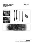
GuardShield™ Type 2 Safety Light Curtain User Manual Important User Information Because of the variety of uses for the products described in this publication, those responsible for the application and use of this control equipment must satisfy themselves that all necessary steps have been taken to assure that each application and use meets all performance and safety requirements, including any applicable laws, regulations, codes and standards. The illustrations, charts, sample programs and layout examples shown in the guide are intended solely for purposes of example. Since there are many variables and requirements associated with any particular installation, Rockwell Automation does not assume responsibility or liability (to include intellectual property liability) for actual use based upon the examples shown in this publication. Rockwell Automation publication SGI-1.1, Safety Guidelines for the Application, Installation and Maintenance of Solid-State Control (available from your local Rockwell Automation sales office), describes some important differences between solid-state equipment and electromechanical devices that should be taken into consideration when applying products such as those described in this publication. Reproduction of the contents of this copyrighted publication, in whole or part, without written permission of Rockwell Automation, is prohibited. Throughout this manual we use notes to make you aware of safety considerations: WARNING IMPORTANT ATTENTION Identifies information about practices or circumstances that can cause an explosion in a hazardous environment, which may lead to personal injury or death, property damage, or economic loss. Identifies information that is critical for successful application and understanding of the product. Identifies information about practices or circumstances that can lead to personal injury or death, property damage, or economic loss. Attentions help you identify a hazard, avoid a hazard, and recognize the consequences. SHOCK HAZARD Labels may be on or inside the equipment (for example, drive or motor) to alert people that dangerous voltage may be present. BURN HAZARD Labels may be on or inside the equipment (for example, drive or motor) to alert people that surfaces may reach dangerous temperatures. It is recommended that you save this user manual for future use. GuardShield™ Type 2 Safety Light Curtain Installation Instructions Conditions required for proper use of the GuardShield Type 2 Safety Light Curtain Please make sure you read and understand these requirements before you select and install the GuardShield Type 2 safety light curtain. GuardShield Type 2 safety light curtains are point of operation safeguarding devices. These safety light curtains are intended to be used to provide point of operation safeguarding of personnel on a variety of machinery. The GuardShield Type 2 family of safety light curtains are general purpose presence sensing devices which are designed to protect personnel working on or near machinery. The installation of GuardShield Type 2 safety light curtains must comply with all applicable federal, state, and local rules, regulations, and codes. It is the responsibility of the employer to properly install, operate and maintain the product as well as the machinery on which the GuardShield Type 2 presence sensing device is installed. GuardShield Type 2 safety light curtains must be properly installed by qualified personnel. GuardShield Type 2 safety light curtains are presence sensing devices and will not protect personnel from heat, chemicals, or flying parts. They are intended to signal a stop of hazardous machine motion when the sensing field is broken. GuardShield Type 2 safety light curtains can only be used on machinery which can be stopped anywhere in its stroke or cycle. GuardShield Type 2 safety light curtains should never be used on full revolution clutched machinery. The effectiveness of the GuardShield Type 2 safety light curtains depends upon the integrity of the machine control circuit. The machinery on which the GuardShield Type 2 presence sensing device is installed should have control circuitry that is fail safe in design. All stopping mechanisms for the machinery should be inspected regularly to ensure proper operation. The protected machinery must have a consistent reliable and repeatable stopping time. ATTENTION Failure to read and follow these instructions can lead to misapplication or misuse of the GuardShield Type 2 safety light curtains, resulting in personal injury and damage to equipment. Original instructions R 1 GuardShield™ Type 2 Safety Light Curtain Installation Instructions Table of Contents IMPORTANT Introduction . . . . . . . . . . . . . . . . . . . . . . . . . . . . . . . . . . . . . .3 Safety Precautions. . . . . . . . . . . . . . . . . . . . . . . . . . . . . . . . . .3 Principles of Safe Use and Symbols Used . . . . . . . . . . . . . . . . . . 3 Specialist Personnel . . . . . . . . . . . . . . . . . . . . . . . . . . . . . . . .3 Range of Uses of the Device. . . . . . . . . . . . . . . . . . . . . . . . . . . . . . 4 Proper Use . . . . . . . . . . . . . . . . . . . . . . . . . . . . . . . . . . . . . . . . . . . . . 4 General Protective Notes and Protective Measures . . . . . . . . . 4 Save these instructions for use at a future time. Generally recognized technical regulations and quality assurance system ISO 9000 are carefully applied during the development and production of Allen-Bradley/ Guardmaster products. This technical description must be followed when installing and commissioning the GuardShield Type 2. Inspection and commissioning must be carried out by a Product Description. . . . . . . . . . . . . . . . . . . . . . . . . . . . . . . .4 Light Curtain Principle of Operation . . . . . . . . . . . . . . . . . . . . . 4 Examples of Range of Use . . . . . . . . . . . . . . . . . . . . . . . . . . . . . . . 5 Response Time . . . . . . . . . . . . . . . . . . . . . . . . . . . . . . . . . . . . . . . . . 5 Rockwell Automation reserves the right to make changes or revisions to the material contained in this publication and cannot be held liable for incidental or consequential damages resulting from the furnishing, performance or use of this material. Determining the Safety Distance. . . . . . . . . . . . . . . . . . . . .6 US Safety Distance Formula . . . . . . . . . . . . . . . . . . . . . . . . . . . . . 6 OSHA Safety Distance Calculation Formula . . . . . . . . . . . . . . 6 The ANSI Safety Distance Formula . . . . . . . . . . . . . . . . . . . . . . 6 European Safety Distance Formula . . . . . . . . . . . . . . . . . . . . . . . 6 Installation and Mounting . . . . . . . . . . . . . . . . . . . . . . . . . .8 Correct Installation . . . . . . . . . . . . . . . . . . . . . . . . . . . . . . . . . . . . . 8 Incorrect Installation . . . . . . . . . . . . . . . . . . . . . . . . . . . . . . . . . . . . 8 Multiple GuardShield Type 2s . . . . . . . . . . . . . . . . . . . . . . . . . . . 9 Mounting Brackets. . . . . . . . . . . . . . . . . . . . . . . . . . . . . . . . . . . . . . 9 Electrical Installation. . . . . . . . . . . . . . . . . . . . . . . . . . . . . 10 Connections . . . . . . . . . . . . . . . . . . . . . . . . . . . . . . . . . . . . . . . . . .10 Typical Wiring Diagram. . . . . . . . . . . . . . . . . . . . . . . . . . . . . . . .11 Troubleshooting Guide. . . . . . . . . . . . . . . . . . . . . . . . . . . . . . . . .12 Checklist. . . . . . . . . . . . . . . . . . . . . . . . . . . . . . . . . . . . . . . . . . . . . .14 Safety Instructions—Maintenance . . . . . . . . . . . . . . . . . 14 Daily Inspection . . . . . . . . . . . . . . . . . . . . . . . . . . . . . . . . . . . . . . .14 Six-month Inspection . . . . . . . . . . . . . . . . . . . . . . . . . . . . . . . . . .15 Cleaning . . . . . . . . . . . . . . . . . . . . . . . . . . . . . . . . . . . . . . . . . . . . . .15 Date Code . . . . . . . . . . . . . . . . . . . . . . . . . . . . . . . . . . . . . . . . . . . .15 Technical Specifications . . . . . . . . . . . . . . . . . . . . . . . . . . . . . . . .16 Type 2 Catalog Numbers . . . . . . . . . . . . . . . . . . . . . . . . . . . . . . .17 Dimensions . . . . . . . . . . . . . . . . . . . . . . . . . . . . . . . . . . . . . . . . . . .18 2 Original instructions R GuardShield™ Type 2 Safety Light Curtain Installation Instructions Introduction The GuardShield Type 2 safety light curtain is a general purpose presence sensing device, designed for use on hazardous machinery providing point of operation, as well as, perimeter and access detection. It is a self-contained, two box, Type 2 ESPE (Electro Sensitive Protective Equipment). The GuardShield Type 2 is offered in either guard only mode or with a restart interlock and EDM. IMPORTANT These installation instructions are designed to address the technical personnel of the machine manufacturer and or the installer of the safety system regarding the proper mounting, configuration, electrical installation, commissioning, operation and maintenance of the GuardShield Type 2 safety light curtain. These installation instructions do not provide instruction for the operation of machinery to which the GuardShield Type 2 safety light curtain is, or will be, integrated. Only qualified personnel should install this equipment. Safety Precautions The GuardShield Type 2 may be used in safety applications in which a risk analysis according to ANSI TR.3, ANSI/RIA 15.06, pr EN 1050 or EN 959-1 have reached Category 2. ATTENTION The GuardShield Type 2 must not be used with machines that cannot be stopped electrically in an emergency. The safety distance between the GuardShield Type 2 and a dangerous machine movement maintained at all times. Additional mechanical protective devices have to be installed in a way that hazardous machine elements cannot be reached without passing through the protective field. The GuardShield Type 2 has to be installed in a way that operators can only operate within the sensing area. Improper installation can result in serious injury. Never connect the outputs to +24V DC. If the outputs are connected to +24V DC, they are in ON-state and cannot stop hazardous spots at the machine/application. Never expose the GuardShield Type 2 to flammable or explosive gases. Regular safety inspections are imperative (see maintenance). Do not repair or modify the GuardShield Type 2. The GuardShield Type 2 safety light curtain is not field repairable and can only be repaired at the factory. Removal of either of the GuardShield Type 2 endcaps will void the warranty terms of this product. Principles for Safe Use and Symbols Used The following instructions are preventive warnings for the proper operation of the GuardShield Type 2. These instructions are an essential part of the safety precautions and therefore have to be observed at any time. Throughout this manual we use the labels ATTENTION and IMPORTANT to alert you to the following: ATTENTION Failure to observe may result in dangerous operation ATTENTION: Identifies information about practices of circumstances that can lead to personal injury or death, property damage, or economic loss. Specialist Personnel The GuardShield Type 2 safety light curtain must be installed, commissioned and serviced only by a qualified person. A qualified person is defined as a person who: • Has undergone the appropriate technical training and • Who has been instructed by the responsible machine operator in the operation of the machine and the currently valid safety guidelines and • Who has read and has ongoing access to these installation instructions ATTENTION helps you • Identify a hazard • Avoid a hazard • Recognize the consequences IMPORTANT: Identifies information that is especially important for successful application and understanding of the product. ATTENTION Potentially hazardous situation, which, if not prevented, might lead to serious or deadly injury. Failure to observe may result in dangerous operation. Original instructions R 3 GuardShield™ Type 2 Safety Light Curtain Installation Instructions Range of Uses of the Device The GuardShield Type 2 safety light curtain is classified as electrosensitive protective equipment (ESPE). The physical resolution is 30 mm (1.18 in.). The maximum protective field width is 18 m (59 ft) for the 30 mm (1.18 in.) resolution GuardShield Type 2. The protective field height is between 160 mm (6.3 in.) and 1760 mm (69.2 in.). The device is a Type 2 ESPE as defined by IEC 61496-1 and CLC/TS 61496-2 and is therefore allowed for use with controls in safety category Type 2 in compliance with EN ISO 13849, SIL CL2 in accordance with EN62061 or up to PLd in accordance with EN ISO 13849. The device is suitable for: • Point of operation protection (finger and hand protection) • Hazardous area protection • Access protection Access to the hazardous point must be allowed only through the protective field. The machine/system is not allowed to start as long as personnel are within the hazardous area. Refer to the “Examples of Range of Use” on page 5 for an illustration of the protection modes. Depending on the application, mechanical protection devices may be required in addition to the safety light curtain. Proper Use The GuardShield Type 2 safety light curtain must be used only as defined in the “Range of Uses of the Device.” It must be used only by qualified personnel and only on the machine where it has been installed and initialized by qualified personnel. If the device is used for any other purposes or modified in any way, warranty claims against Allen-Bradley/Guardmaster shall become null and void. General Protective Notes and Protective Measures ATTENTION Safety Notes Please observe the following items in order to ensure compliance of the proper and safe use of the GuardShield Type 2 safety light curtain. • The national/international rules and regulations apply to the installation, use and periodic technical inspections of the safety light curtain, in particular: ♦ ♦ ♦ ♦ ♦ Machine Directive 2006/42/EC Low Voltage Directive 2006/95/EC Use of Work Directive 2009/104EC The work safety regulations/safety rules Other relevant health and safety regulations • The tests must be carried out by specialist personnel or specially qualified and authorized personnel and must be recorded and documented to ensure that the tests can be reconstructed and retraced at any time. • The installation instructions must be made available to the user of the machine where the GuardShield Type 2 safety light curtain is installed. The machine operator is to be instructed in the use of the device by specialist personnel and must be instructed to read the installation instructions. Product Description This section provides information on the special features and properties of the safety light curtain. It describes the structure and functions of the unit, in particular the different operating modes. → Please read this section before mounting, installing and commissioning the unit. GuardShield Type 2 Light Curtain Principle of Operation The GuardShield Type 2 safety light curtain consists of a non-matched pair of optic units, i.e., transmitter and receiver with the same protected height and resolution. The transmitter and receiver operate on +24V DC. The maximum distance between transmitter and receiver is referred to as the protective field width or range. The protective field height is the distance between the first and last beam in the device. The transmitter emits sequential pulses of infrared light which are received and processed by the GuardShield Type 2 receiver. The synchronization of the timing of the emission and reception of infrared light pulses is accomplished optically by the first beam adjacent to the GuardShield Type 2 status LEDs. This beam is referred to as the synchronization beam. Because the GuardShield Type 2 transmitter and receiver are optically synchronized, no electrical connection is required between the transmitter and receiver. The GuardShield Type 2 receiver has two safety outputs, Output Signal Switching Devices (OSSDs) and one nonsafety auxiliary output. When the GuardShield Type 2 transmitter and receiver are properly powered and aligned, all OSSDs are current sourcing +24V DC with a switching capacity of 500 mA. The two safety OSSDs are cross monitored and short-circuit protected. Interruption of the sensing field causes the receiver to switch the sourced current OFF (0V DC). Restoring the GuardShield Type 2 sensing field, (in Guard only configuration) causes all outputs (OSSDs) to switch to the active high state (resume current sourcing +24V DC with a switching capacity of 500 mA). The GuardShield Type 2 Light Curtain Manufacturers and users of the machine with which the safety light curtain is used are responsible for obtaining and observing all applicable safety regulations and rules. The GuardShield Type 2 safety light curtain consists of a transmitter and a receiver. • The notices, in particular the test regulations of these installation instructions (e.g. on use, mounting, installation or integration into the existing machine controller) must be observed. 4 Original instructions R GuardShield™ Type 2 Safety Light Curtain Installation Instructions GuardShield Type 2 is factory ordered with this functionality. Indication of this mode of operation is through illumination of a yellow LED on the GuardShield Type 2 receiver. Restart Interlock Figure 1: Components of the GuardShield Type 2 The upper and lower limit of the protective field is shown by markings on the housings. The width of the protective field is derived from the length of the light path between sender and receiver and must not exceed the maximum rated width of the protective field (18 m…30 mm (59.0 ft…1.18 in.)). Examples of Range of Use The GuardShield Type 2 safety light curtain operates as a proper protective device only if the following conditions are met: • The control of the machine must be electrical. • The controlled machine must be able to be stopped any where in the machines stroke or cycle. • The transmitter and receiver must be mounted such that access to the hazard is only through the light curtain’s protective field. • The restart button must be located outside the hazardous area such that it cannot be operated by a person working inside the hazardous area. • The statutory and local rules and regulations must be observed when installing and using the device. IMPORTANT IMPORTANT Additional measures may be necessary to ensure that the ESPE does not fail to danger when other forms of light radiation are present in a particular application (i.e., use of cableless control devices on cranes, radiation from weld spatter or effects from strobe lights). The protective system must be tested for proper operation after each and every change to the configuration. Guard Only When in the guard only mode of operation, the light curtain operates as an on/off device, meaning the OSSD outputs switch off/on according to an obstruction or clearing of the detection field. Start Interlock The start interlock is designed to protect against the OSSD outputs from switching to ON state after power up of the system with the protective field unobstructed. A manual reset of the system is required for the GuardShield Type 2 to enter the ON state. This can be accomplished by one of two methods. • Actuation of a momentary N.O. push button • Interruption and restoration of the protective field within one second. The restart interlock mode of operation is designed to protect against the OSSD outputs from switching to ON after interruption and clearance of the protective field. A manual reset of the GuardShield Type 2 system is required. Resetting of the system is accomplished through a momentary N.O. push button or key switch. The restart interlock mode is indicated by the illumination of a yellow LED on the GuardShield Type 2 receiver. GuardShield Type 2 is factory ordered with this functionality. Relay Monitoring (MPCE/EDM) The relay monitoring function is an input signal to the GuardShield Type 2 receiver and is used to monitor the state of the protected machinery’s primary control contactors or other final switching device. Detection of unsafe conditions such as welded contacts, cause the GuardShield Type 2 to enter a lockout condition (OSSDs OFF). System Testing The GuardShield Type 2 performs a complete system self-test at power up and switches to the ON state if the system is properly aligned and the protective field is unobstructed. If the start/restart interlock version is used, a reset is required to switch to a “green” state. External Test (Machine Test Signal) A test cycle of the system can be triggered by an external test signal to the GuardShield Type 2 transmitter. Supplying or removing a signal (+24V DC) via a N.C. or N.O. switch at the test input deactivates the transmitter for the duration of the test signal, simulating an interruption of the protective sensing field. Response Time The response time of the GuardShield Type 2 safety light curtain depends on the height of the protective field, the resolution and the number of light beams as well as the coding of the system. Resolution [mm (in.)] Protective Height [mm (in.)] Number of Beams 30 (1.18) 160 (6.3) 8 20 ms 30 ms 30 (1.18) 320 (12.5) 16 20 ms 30 ms 30 (1.18) 480 (18.8) 24 20 ms 30 ms 30 (1.18) 640 (25.1) 32 20 ms 30 ms 30 (1.18) 800 (31.4) 40 20 ms 30 ms 30 (1.18) 960 (37.7) 48 20 ms 30 ms 30 (1.18) 1120 (44.0) 56 20 ms 30 ms 30 (1.18) 1280 (50.3) 64 20 ms 30 ms 30 (1.18) 1440 (56.6) 72 20 ms 30 ms 30 (1.18) 1600 (62.9) 80 20 ms 30 ms 30 (1.18) 1760 (69.2) 88 20 ms 30 ms Original instructions R Response Time Response Time w/o Coding w/Coding 5 GuardShield™ Type 2 Safety Light Curtain Installation Instructions IMPORTANT machine’s control circuit and any other devices that react to stop the hazardous motion of the machinery. Not including the response time of a device or devices in the stop time calculation will result in insufficient safety distance for the application. This may result in operator injury. Determining Stop Time: The measurement of stopping time (Ts) must include the stopping times of all devices in the stop circuit. Not including all device and control system elements when calculating Ts will result in an inaccurate safety distance calculation. The ANSI Safety Distance Formula The ANSI safety distance formula, which is the Rockwell Automation recommended formula, is as follows: Determining the Safety Distance The light curtain must be mounted with proper safety distance • From the point of danger • From reflecting surfaces US Safety Distance Formula ATTENTION Regardless of the calculated safety distance, GuardShield Type 2 safety light curtains should never be mounted closer than six inches from the point of operation or pinch In the United States there are two formulas that are used to properly calculate the safety distance. The first, the OSHA formula, is the minimum requirement for the calculation of the safety distance. The second formula, the one recommended by Rockwell Automation, is the ANSI formula, which incorporates additional factors to be considered when calculating the safety distance. OSHA Safety Distance Calculation Formula The OSHA safety distance formula as specified in CFR Subpart O 1910.217 is as follows: Ds = 63 X TS 6 Hand speed constant in inches per second. The ANSI standard value is 63 inches per second when the operator begins reaching toward the point of operation hazard from rest. NOTE: ANSI B11.19 1990 E4.2.3.3.5 states “The value of the hand speed constant, K, has been determined by various studies and although these studies indicate speeds of 63 inches/second to over 100 inches/second, they are not conclusive determinations. The employer should consider all factors, including the physical ability of the operator, when determining the value of K to be used.” Ts Stop time of the machine tool measured at the final control element. Tc Response time of the control system Note: Ts and Tc are usually measured by a stop time measuring device. Tr Response time of the presence sensing device (safety light curtain) and its interface, if any. This value is generally stated by the device manufacturer or it can be measured by the user. Tbm Additional time allowed for the brake monitor to compensate for variations in normal stopping time. Dpf Depth penetration factor. It is an added distance to allow for how far into the protective field an object, such as a finger or hand, can travel before being detected. Dpf is related to the safety light curtain’s object sensitivity. Object sensitivity is the smallest diameter object which will always be detected anywhere in the sensing field. European Safety Distance Formula Ds Safety Distance 63 Is the OSHA recommended hand speed constant in inches per second Ts Is the total stop time of all devices in the safety circuit, measured in seconds. This value must include all components involved in stopping the hazardous motion of the machinery. For a mechanical power press it is the stopping time measured at approximately the 90º position of the crankshaft rotation. Note: DS = K x (TS + TC + Tr + Tbm) + Dpf Minimum safety distance between the safe guarding device and the nearest point of operation hazard, in inches. K The GuardShield Type 2 safety light curtains must be mounted at a sufficient distance from the pinch point or point of operation hazard to ensure that the machine stops before a person’s finger, hand, arm(s), or This distance, referred to as the safety distance, must be properly calculated prior to determining the safety light curtain protective height and mounting the light curtains on the machine. Failure to properly calculate this safety distance may result in operator injury. IMPORTANT Ds The TS number must include the response times of all devices, including the response time of the safety light curtain, the safety light curtain controller (if used), the A safety distance must be maintained between the light curtain and the point of danger. This safety distance helps ensure that the point of danger can only be reached after the dangerous state of the machine has been completely removed. The safety distance as defined in EN ISO 13855 and EN ISO 13857 depends on: • Stopping/run-down time of the machine or system. (The stopping/run-down time is shown in the machine documentation or must be determined by taking a measurement.) • Response time of the protective device, e.g. GuardShield Type 2 (for “Response Time” see page 5). • Reach or approach speed. Original instructions R GuardShield™ Type 2 Safety Light Curtain Installation Instructions • Resolution of the light curtain and/or beam separation. Minimum Distance from Reflecting Surfaces The infrared light from the sender may be reflected off of shiny surfaces and be received by the system’s receiver. If this condition occurs, it can result in an object not being detected when it enters the GuardShield Type 2 sensing field. Safety distance S (Ds) All reflecting surfaces and objects (e.g. material bins) must therefore be located at a minimum distance a from the protective field of the system. The minimum distance a depends on the distance D between sender and receiver. Protective field height Point of danger a Distance to avoid standing behind the safety curtain ≤75mm Distance D (meters) Figure 2: Safety distance from the point of danger Figure 3: Minimum distance from reflecting surfaces How to Calculate the Safety Distance S According to EN ISO 13855 and EN ISO 13857: → First, calculate S using the following formula: S = 2000 × T + 8 × (d – 14) [mm] How to Determine the Minimum Distance from the Reflecting Surfaces: → Determine the distance D [m] sender-receiver → Read the minimum distance a [mm] from the graph: Where … T = stopping/run-down time of the machine + response time of the protective device [s] d = resolution of the light curtain [mm] S = safety distance [mm] The reach/approach speed is already included in the formula. → If the result S is ≤ 500 mm (19.6 in.), then use the determined value as the safety distance. → If the result S is > 500 mm (19.6 in.), then recalculate S as follows: S = 1600 × T + 8 × (d – 14) [mm] → If the new value S is > 500 mm (19.6 in.), then use the newly determined value as the minimum safety distance. → If the new value S is ≤ 500 mm (19.6 in.), then use 500 mm (19.6 in.) as the safety distance. Example: a (mm) 1600 1500 1400 1300 1200 1100 1000 900 800 700 600 500 400 300 200 100 Stopping/run-down time of the machine = 290 ms Response time = 30 ms Resolution of the light curtain = 30 mm (1.18 in.) T = 290 ms + 30 ms = 320 ms = 0.32 s S = 2000 × 0.32 + 8 × (30 – 14) = 768 mm (30.24 in.) S > 500 mm, therefore: S = 1600 × 0.32 + 8 × (30 – 14) = 640 mm (25.1 in.) D (m) 3 5 10 15 20 Figure 4: Graph, minimum distance from reflecting surfaces Example: In opto-electronic safeguarding, such as with a perpendicular safety light curtain applications with object sensitivity (effective resolution) less than 2.5 inches, the Dpf can be approximated based on the following formula: Dpf (inches) =3.4 × (Object Sensitivity – 0.276), but not less than 0. Original instructions R 7 GuardShield™ Type 2 Safety Light Curtain Installation Instructions The effective aperture angle for the GuardShield Type 2 system is within ±5.0° at a mounting distance of > 3.0 m (9.8 ft). Calculate the minimum distance to reflecting surfaces depending on the distance between the transmitter and the receiver, using an aperture angle of ±5.0°, or take the appropriate value from the following table: Distance Between Transmitter and Receiver (Range X)D [m (ft)] Minimum Distance a [mm (in.)] 0.2…3.0 (0.65…9.8) 263 (10.4) 4.0 (13.1) 350 (13.8) 5.0 (16.4) 437 (17.2) 6.0 (19.6) 525 (20.7) 7.0 (22.9) 613 (24.1) 10.0 (32.8) 875 (34.5) 16.0 (52.4) 1400 (55.1) 18.0 (59.1) 1575 (62.0) IMPORTANT The installation of the GuardShield Type 2 safety light curtain must be such that access to the hazard is only possible through the sensing field of the GuardShield Type 2. Auxiliary safe guarding may be required in conjunction with the GuardShield Type 2 to meet this requirement. Determine if the machinery, on which the GuardShield Type 2 is to be mounted, meets the requirements as specified in the beginning of this manual, i.e., machinery must be able to be stopped anywhere in its stroke or cycle, consistently and repeatedly. Correct Installation Operators cannot reach hazardous machine parts without passing through the protective field. Note: Formula: a = tan 2.5° x D [mm] a = minimum distance to reflecting surfaces D = distance between transmitter and receiver Installation and Mounting This section describes the preparation, selection and installation of the GuardShield Type 2 safety light curtain. Operators must not step between protective field and hazardous machine parts (by-pass prevention). The standard GuardShield Type 2 has an amber LED in the receiver which is used as an alignment aid. This LED will begin flashing when the infrared light from the transmitter is “seen” by the receiver. This LED turns off when optimal alignment is attained. Alignment Procedure: Standard GuardShield Type 2 Incorrect Installation Mount and connect both transmitter and receiver. They must be parallel to each other and be positioned at the same height. Turn on power to GuardShield Type 2 system. Operators can reach hazardous machine parts without passing through the protective field. Rotate the transmitter while watching the amber LED on the receiver to find the point where the indicator for the ON state (Green LED) illuminates and the amber LED goes off. Determine the maximum left and right turning angles and position unit in center. Tighten all hardware assuring that the alignment indicator is not illuminated. Cycle power to assure that the system powers up and goes to the ON state (alignment indicator is OFF). Operators can step between protective field and hazardous machine parts. An external laser (440L-ALAT) and mounting bracket (440LAF6109) is offered as an accessory for aligning the GuardShield Type 2. The GuardShield Type 2 safety light curtain is suitable for most operating environments (IP65 environmental rating). Proper safety distance as well as adequate protective height must be observed. The GuardShield Type 2 must be mounted at the proper distance from the point of operation hazard. This distance is referred to as the Safety Distance. 8 Original instructions R GuardShield™ Type 2 Safety Light Curtain Installation Instructions Middle of Depth of Protective Field 20 (0.79) 52 (2.04) Point of Operation Safety Distance 42 (1.65) 18.9 Top of tool 14.5 Machine stop time 6.5 (0.26) Protective Field Marking 40 (1.57) 3.0 Bottom of tool To avoid the possibility of standing between the protective field and the point of operation, the distance must be maintained. 32 (1.25) Figure 5: Determining machine stopping time and safety distance Multiple GuardShield Type 2 Figure 7: Mounting brackets When two or more GuardShield Type 2 are mounted in close proximity to one another, it may be possible for the receiver of one GuardShield Type 2 pair to receive infrared light from the transmitter of another GuardShield Type 2 pair. If two or more pair of GuardShield Type 2 are mounted in the same plane, the transmitter and receiver pairs must be mounted in accordance with Figure 6 or a barrier is used to guard against optical interference. Optional Middle Mounting Bracket (440L-AF6108) 49.2 (1.93) 30 (1.18) 20 (0.78) 40.2 62 Transmitters emit in opposite direction. Each receiver receives only the beams of the appropriate transmitter. 24 Figure 8: Positioning of the light curtain: Transmitters emit in opposite direction. Note: Middle mounting brackets should be used in vibration applications for protective heights of 1120 mm and larger. Figure 6: Multiple GuardShield Type 2 alignment options Mounting Brackets The GuardShield Type 2 is mounted using right angle brackets attached to the endcaps of both transmitter and receiver. It may be necessary to use additional brackets to mount the GuardShield Type 2 at a proper safety distance from the machinery hazard. Original instructions R 9 GuardShield™ Type 2 Safety Light Curtain Installation Instructions Electrical Installation Connections Power Supply The external voltage supply (+24V DC) must meet the requirements of IEC 61496-1. In addition, the following requirements have to be fulfilled: • A short-term power failure of 20 ms must be bridged by the power supply. • The power supply has double insulation between the primary and the secondary side. • The power supply is protected against overload. • The power supply corresponds to the guidelines of the EWG (industrial environment). • The power supply corresponds to the Low Voltage Directives. • The grounded conductor of the power supply device must be connected to a grounded conductor PE. • The maximum deviation of the voltage levels is 24V DC +/- 20%. Double insulation Basic insulation Output (pink GuardS hield Basic insulation Reset/restart button Pin 8 24V Figure 10: Connecting the reset button/restart button Connections [mm (in.)] This part of the insulation provides supplementary insulation against hazardous voltage levels. 0V (blue) +24V (brown) K1 K1 K2 K2 Motor, etc. Cables/Connectors Power Supply Unit Unit 1 The GuardShield Type 2 transmitter connector is a four-pin DC micro connector offered in cable lengths from 2 to 30 meters. The GuardShield Type 2 receiver connector is an 8-pin DC micro connector offered in cable lengths of 2 to 30 meters. Hazardous voltage level Basic insulation Reinforced insulation or double Hazardous Hazardous Transmitter Connection Face View of Female DC Micro EDM Connection 2 3 1 4 Signal Color Pin No. Brown 1 Transmitter +24V DC White 2 No Connection Blue 3 0V DC Black 4 Machine Test Signal Standard GuardShield Type 2 Receiver Connector Pin 4 24V k2 Contactor k1 Contacts 5 6 Receiver Connection Face View of Female DC Micro K1 K2 Contactor Coils Figure 9: Connecting the contact elements to the EDM 3 Start/Restart interlock 8 Note: Start/restart interlock requires a N.O. momentary push button or key switch. 10 4 2 5 1 7 6 Signal Color Pin No. Receiver White 1 Auxiliary Output Brown 2 +24V DC Green 3 Ground Yellow 4 EDM Grey 5 OSSD 1 OSSD 2 Pink 6 Blue 7 0V DC Red 8 Start/Restart Original instructions R GuardShield™ Type 2 Safety Light Curtain Installation Instructions Typical Wiring Diagram (Direct to contactors if GuardShield Type 2 with start/restart interlock and EDM is factory ordered) + 24VDC SENDER S2 Start/Restart RECEIVER Brown Brown Red Gray L1 L2 L3 OSSD 1 K2 S1 Test Machine Test Signal Pink Bulletin 100S Safety Contactors or 700S Safety Relays OSSD 2 Black K1 Yellow MPCE/EDM White Blue Blue M Auxiliary Signal Green 24V Ground ➊ Nonsafety auxiliary output can be connected to a lamp, motor or status to a PLC. Note: If MPCE/EDM is not used, the GuardShield Type 2 OSSDs should be connected to a safety relay module, which is configured for EDM. Typical Wiring Diagram—To MSR127 Safety Relay Module +24V L1 1 Transmitter Receiver 2 OSSD1 OSSD2 5 6 3 A S52 S12 L2 L3 7 13 23 33 41 K4 MSR127RP K5 A2 S21 S22 K4 S34 14 24 34 42 K5 Reset K4 K5 M DC Common ATTENTION The GuardShield Type 2 is a Type 2 safety device. The use of a Category 4 safety relay in a safety circuit will not increase the safety level of the safety circuit above a Category 2. Original instructions R 11 GuardShield™ Type 2 Safety Light Curtain Installation Instructions Troubleshooting Guide The light curtain carries out an internal self-test after startup. If an error occurs, an appropriate signal combination is sent through the LEDs to the transmitter and receiver. Condition No. 6 Error Description Internal fault, receiver • Replace receiver Internal fault, transmitter • Check connections transmitter/ receiver • Exchange transmitter External fault • Check connections of OSSD outputs for short circuit against +24V DC and GND (cable, connected devices) • Replace receiver External fault (MPCE error) The function Relay monitoring is activated and after clearing the OSSD the input Relay monitoring does not recognize a change of state. • Check connection Relay monitoring • Check connected relay for closed contact (if OSSD ON—input Relay monitoring must have GND level, if OSSD OFF—input Relay monitoring must have +24V) • Switch on only after POWER OFF/ ON 7 8 9 12 Action Original instructions R GuardShield™ Type 2 Safety Light Curtain Installation Instructions System Status Indicators Receiver OSSDs ON Transmitter OSSDs OFF Power Emitting Alignment Interlock Receiver LEDs OSSDs OFF Condition No. OSSDs ON Red Transmitter LEDs Alignment Green Interlock Amber Yellow Power On Amber Emitting Yellow 1 OFF ON OFF OFF ON ON 2 ON OFF OFF OFF ON ON 3 ON OFF ON OFF ON ON 4 ON OFF OFF ON ON ON 5 ON OFF OFF OFF ON OFF 6 FLASH OFF OFF OFF ON ON 7 ON OFF OFF OFF FLASH ON 8 FLASH OFF ON OFF ON ON 9 FLASH OFF OFF ON ON ON 6 through 9 = Fault conditions Flash rate is approximately. 2 Hz (2 times per second) Condition No. Description 1 Guard only mode, light curtain unobstructed (aligned, not in interlock) 2 Guard only mode, light curtain interrupted (aligned, not in interlock) 3 Guard only mode, misaligned (not in interlock) 4 Restart interlock (aligned) 5 Transmitter test input active (pin 4) 6 Internal fault, receiver 7 Internal fault, transmitter 8 External fault (OSSD short to ground, +V, or cross connection) 9 External fault (MPCE/EDM error) Note: For fault conditions 6 through 9, see Troubleshooting guide on page 12. Original instructions R 13 GuardShield™ Type 2 Safety Light Curtain Installation Instructions ATTENTION IMPORTANT Assure that all power to the machine, and safety system is disconnected during electrical installation. Prior to powering up the GuardShield Type 2 system, the responsible person should review the following Checklist. Safety Instructions—Maintenance ATTENTION Never operate the GuardShield Type 2 before carrying out the following inspection. Improper inspection can lead to serious or even deadly injury. Note: 1. For safety reasons all inspection results should be recorded. Checklist Before the initiation of the GuardShield Type 2 the responsible person should work through the following checklist. Cable check prior to initiation: 1. The power supply is solely connected to the GuardShield Type 2. 2. The power supply is a 24V DC device, that must comply to all applicable standards of the Machinery Directive 2006/42/EC, and the product standard (IEC 61496). 2. Only persons, who clearly understand the functioning of the GuardShield Type 2 and of the machine, may carry out an inspection. 3. If installer, planning engineer and operator are different people, make sure that the user has sufficient information available to carry out the inspection. Daily Inspection 3. Proper polarity of the power supply at the GuardShield Type 2. 1. 4. The transmitter connection cable is properly connected to the transmitter, the receiver connection cable is properly connected to the receiver. Approach to hazardous machine parts must only be possible through passage through the protective field of GuardShield Type 2. 2. The double insulation between the light curtain output and an external potential is ensured. Operators cannot step through the sensing area while working on dangerous machine parts. 3. The safety distance of the application is bigger than the calculated value. 4. The optic front cover is neither scratched nor dirty. 5. 6. The OSSD outputs are not connected to +24V DC. 7. The connected switching elements (load) are not connected to 24V DC. 8. No connection to a conventional power supply. 9. If two or more GuardShield Type 2 are to be used, make sure that each system is properly installed, in order to avoid optical interference. Operate the machine and check, if the hazardous movement will stop under the following circumstances. 5. The protective field is interrupted. 6. Hazardous machine movement stops immediately, if the protective field is interrupted by the test rod directly in front of the transmitter, directly in front of the receiver and in the middle between transmitter and receiver. 7. No hazardous machine movement while the test rod is anywhere within the protective field. 8. The power supply of the GuardShield Type 2 is turned off. 9. If the blanking function is activated, check all sections of the protective field with the appropriate test piece. Switch the GuardShield Type 2 on and check its function by observing the following: 10. Two seconds after switching on, the system starts to work properly, if the protective field is free of obstructions. IMPORTANT 14 If any of the above conditions do not result in the hazardous motion of the machine ceasing, do not allow the protected machine to be placed in operation. Original instructions R GuardShield™ Type 2 Safety Light Curtain Installation Instructions Date Code Bul/Type Receiver Transmitter Part No. 440L Ambient Temp -10.....+55C Ser Rev A A T2KA0320YD Ref No. Power Consumption 7W max. Supply Voltage 24V DC +/-20% Made in Jun, 2010 Safety Parameters Type 2/Cat.2 IEC61496/ EN ISO 13849 EN62061/ IEC61508 AA00AA00 Operating Instructions PLD/SIL CL2,SIL2 PN-20857 GuardShield TM Rockwell Automation 2 Executive Dr. Chelmsford MA. 01824 Degree of Protection IP65 978-441-9500 Resolution 30mm Electro-Sensitive Product of Mexico Proper testing of protective field using test rod Protective Equip. 19KP Six-Month Inspection Range 0.3-16m Protective Height Check the following items every six months or whenever a machine setting was changed. Bul/Type 440L Part No. T2KA0320YD A A 320mm Response Time with Coding <30ms Ser Rev Response Time w/o Coding <20ms 1. Machine stops or does not obstruct any safety function. 2. The latest machine or connection modifications have no effect on the control system. Location of Manufacture Year of Manufacturer Week of Manufacturer X X* XX The outputs of the GuardShield Type 2 are properly connected to the machine. M or 4K R 02 3. 4. The total response time of the machine is shorter than the calculated value. 5. Cables and plugs of the GuardShield Type 2 are in flawless condition. 6. Mounting brackets, caps and cables are tightly secured. M represented Manchester, NH replaced by 4K for Monterrey, Mexico * J=2004 K=2005 L=2006 M=2007 N=2008 P=2009 R=2010 S=2011 T=2010 U=2013 V=2014 W=2015 Y=2016 Z=2017 Explanation of data code Cleaning If the optic front cover of the GuardShield Type 2 is dirty, the outputs of the GuardShield Type 2 turn off. Take a clean, soft cloth and rub without pressure. Do not apply aggressive, abrasive or scratching cleansing agents, which might attack the surface. Original instructions R 15 GuardShield™ Type 2 Safety Light Curtain Installation Instructions Technical Specifications Light Beams 8 – 88 Protective Field 160…1760 mm (6.3…69.29 in.) in 160 mm (6.3 in.) increments Resolution 30 mm (1.18 in.) Range 30 mm (1.18 in.); 0.3…18.0 m (0.98…59.0 ft) Response Time OSSD – ON to OFF: (Reaction times); 20…25 ms Power Supply 24V DC +/-20%; Power supply must meet the requirements of IEC 60204-1 and IEC 61496-1. Power Consumption 400 mA max. (unloaded) IR Transmitter Infrared LED (wave length 870 nm) Aperture Angle Within ± 5.0° for transmitter and receiver Operating Condition IR transmitter ON Functions Guard Only: Start Interlock: Restart Interlock: Relay Monitoring: Test Function: On/Off operation with clear/obstructed detection area Interlock at start up—Reset by actuation of momentary N.O. pushbutton switch (or interruption/restoration of light curtain) Interlock at interruption of sensing field—Reset by actuation of momentary N.O. pushbutton switch Monitoring a switch contact of the installation Triggering of system test via external switch Inputs Transmitter Machine Test Signal Minimum duration 100 ms Voltage level for Logic 0: Inputs Receiver 0…5V DC Voltage level for Logic Hi 1: > 16V DC Logic Lo Start/Restart Interlock Minimum duration 100 ms; maximum duration 900 ms Voltage level for Logic Lo 0: 0…5V DC Voltage level for Logic Hi 1: > 16V DC MPCE 300 ms after activation of OSSD Voltage level for Logic 0: 0…5V DC Voltage level for Logic Hi 1: > 16V DC Outputs: Safety Outputs (OSSDs) 2 solid state outputs, max. switching capacity 500 mA, short circuit protected, max. residual voltage 2V (excl. voltage drop through cables) Auxiliary Output Solid state output, max. power consumption 500 mA, max. residual voltage 2V—nonsafety output Status Indicators Receiver ON-state Constant ON when system is in ON-state (green LED) OFF-state Constant ON when system is in OFF-state (red LED) • Lights up at interruption of protective field or if fault occurs Alignment Lights up, if input signal is too weak (amber LED) Interlock Lights up when light curtain is in start or restart interlock mode (yellow LED) Status Indicators Sender Power ON Lights up, when voltage is on (amber LED) Emitting Constant ON when transmitter is active (yellow LED) QD Connectors Transmitter: M12 plug 4 pin; receiver: M12 plug 8 pin Cable Length Maximum 30 m (100 ft) Ambient Temperature During operation: –10…55°C (14…131°F); For storage: –25…75°C (-13…167°F) Humidity of the Air Up to 95% (without condensation) between 20°C and 55°C (68°F and 131°F) Enclosure Rating IP65 Vibration Resistance Per IEC 61496-1, IEC 60068-2-6 Frequency 10…55 Hz Amplitude 0.35 mm Shock Per IEC 61496-1, IEC 60068-2-29 Acceleration 10 g, Duration 16 ms Material Housing: Aluminum; Cover: PMMA (acrylic) Dimensions (cross section) Approx. 40 x 50mm (1.57 x 1.96 in.) Accessories Included Test rod, mounting brackets, operating instructions Approvals IEC 61496 Parts 1and 2, UL 61496 Parts 1 and 2, UL 1998 Safety Classification Type 2 per EN/IEC 61496, Category 2 EN/ISO 13849, SIL 2, IEC 61508, SIL CL2, EN 62061, PLd, EN/ISO 13849 PFHd (mean probability of a dangerous failure/hr Standalone sys.: 9.51 x 10⁻⁹ TM (mission time) 20 years (EN ISO 13849) Transmitter Wave Length 870 nm 16 Original instructions R GuardShield™ Type 2 Safety Light Curtain Installation Instructions GuardShield Type 2 Catalog Numbers No. of Beams Protective Heights— mm (in) Pair Weight— kg (lbs) Sensor Pair Transmitter Receiver Resolution—mm (in) 440L-P2K⊗0160YD 440L-T2KA0160YD 440L-R2K⊗01604D 30 (1.18) 8 160 (6.2) 0.9 (1.9) 16 320 (12.59) 1.1 (2.4) 440L-P2K⊗0320YD 440L-T2KA0320YD 440L-R2K⊗0320YD 30 (1.18) 440L-P2K⊗0480YD 440L-T2KA0480YD 440L-R2K⊗0480YD 30 (1.18) 24 480 (18.89) 1.6 (3.5) 440L-P2K⊗0640YD 440L-T2KA0640YD 440L-R2K⊗0640YD 30 (1.18) 32 640 (25.19) 2.0 (4.4) 440L-P2K⊗0800YD 440L-T2KA0800YD 440L-R2K⊗0800YD 30 (1.18) 40 800 (31.49) 2.5 (5.5) 48 960 (37.79) 2.9 (6.4) 440L-P2K⊗0960YD 440L-T2KA0960YD 440L-R2K⊗0960YD 30 (1.18) 440L-P2K⊗1120YD 440L-T2KA1120YD 440L-R2K⊗1120YD 30 (1.18) 56 1120 (44.09) 3.4 (7.5) 440L-P2K⊗1280YD 440L-T2KA1280YD 440L-R2K⊗1280YD 30 (1.18) 64 1280 (50.39) 3.8 (8.4) 440L-P2K⊗1440YD 440L-T2KA1440YD 440L-R2K⊗1440YD 30 (1.18) 72 1440 (56.69) 4.3 (9.5) 80 1600 (62.99) 4.7 (10.4) 88 1760 (69.29) 5.2 (11.5) 440L-P2K⊗1600YD 440L-T2KA1600YD 440L-R2K⊗1600YD 30 (1.18) 440L-P2K⊗1760YD 440L-T2KA1760YD 440L-R2K⊗1760YD 30 (1.18) Catalog Number Explanation 440L - P 2 ⊗ K 03 20 Y D Connector Option Micro QD Environmental Rating IP65 0160 - Protective Height 0320 0480 0960 1440 0640 1120 1600 0800 1280 1760 Operating Modes A = Guard Only D = Restart Interlock with EDM K- 30 mm (1.18 in.) Type 2 P - Pair, T - Transmitter, R - Receiver Bulletin Number Original instructions R 17 GuardShield™ Type 2 Safety Light Curtain Installation Instructions Dimensions [mm (in.)] 80 min (3014) 11 (0.43) 52 (2.05) 45 (1.77) A 40 (1.57) 440L-AF6108 Middle Mounting Bracket to be used in vibration applications for units greater than 800mm (31.4in) 40 (1.57) 42 20 (1.65)(0.79) B C ⊗ 18 Type A Protective Height B Mounting Value C Total Length 440L-P2K⊗0160YD 160 ±0.5 285 321 ±1.5 440L-P2K⊗0320YD 320 ±0.5 445 481 ±1.5 440L-P2K⊗0480YD 480 ±0.5 605 641 ±1.5 440L-P2K⊗0640YD 640 ±0.5 765 801 ±1.5 440L-P2K⊗0800YD 800 ±0.5 925 961 ±1.5 440L-P2K⊗0960YD 960 ±0.5 1085 1121 ±1.5 440L-P2K⊗1120YD 1120 ±0.5 1245 1281 ±1.8 440L-P2K⊗1280YD 1280 ±0.5 1405 1441 ±1.8 440L-P2K⊗1440YD 1440 ±0.5 1565 1601 ±1.8 440L-P2K⊗1600YD 1600 ±0.5 1725 1636 ±2.0 440L-P2K⊗1760YD 1760 ±0.5 1885 1796 ±2.0 A is guard only mode; D is restart interlock with EDM. Original instructions R GuardShield™ Type 2 Safety Light Curtain Installation Instructions Optional Accessories Description Cat. No. Steel L-shaped end cap mounting bracket (4 per package) Note: 4 brackets supplied with each GuardShield Type 2 pair. 440L-AF6101 Aluminum middle mounting bracket for vibratory applications 440L-AF6108 Power supply: Output—24V DC, 3 Amps, 72 W 1606-XLP72E Laser alignment tool 440L-ALAT GuardShield Type 2 laser alignment tool bracket 440L-AF6109 Mounting stand 440L-AMSTD Vertical shock mount kit 440L-AF6120 Horizontal shock mount kit 440L-AF6121 Middle vertical mount kit 440L-AF6122 Middle horizontal mount kit 440L-AF6123 440L-AGWS0160 440L-AGWS0320 440L-AGWS0480 440L-AGWS0640 440L-AGWS0800 GuardShield Type 2 weld shield pair 440L-AGWS0960 440L-AGWS1120 440L-AGWS1280 440L-AGWS1440 440L-AGWS1600 440L-AGWS1760 Original instructions R 19 GuardShield™ Type 2 Safety Light Curtain Installation Instructions Mirror 440L-AM075 Mirror 440L-AM125 8 x 13 Section A 44.4 75 (174) (2.65) 164 (6.45) "Z" 50 (1.96) 54 (2.12) 35 (1.37) 13.3 (0.52) 73 (2.87) "Z" 6.5 (0.25) 2.5 (0.09) 4.5 (0.17) 10.5 (0.41) 164 (6.45) 50 (1.96) A B L ±120° A A Ls L 396 (15.60) Ls 340 (13.4) A 372 (14.64) B 440 (17.32) 10.5 (0.41) A 4.5 (0.17) 2.5 (0.09) A 6.5 (0.25) Section A-A +/- 120° 13.3 (5.24) 35 (1.37) 123 (4.84) 54 (2.12) 44.4 (1.74) 75 (2.95) 50 (1.96) 114 (4.48) 20 Model No. 440L-AM0750300 Series A Description Mirror, 300 mm, 4 m 440L-AM0750450 440L-AM0750600 440L-AM0750750 440L-AM0750900 440L-AM0751050 440L-AM0751200 440L-AM0751350 440L-AM0751500 440L-AM0751650 440L-AM0751800 A A A A A A A A A A Mirror, 450 mm, 4 m Mirror, 600 mm, 4 m Mirror, 750 mm, 4 m Mirror, 900 mm, 4 m Mirror, 1050 mm, 4 m Mirror, 1200 mm, 4 m Mirror, 1350 mm, 4 m Mirror, 1500 mm, 4 m Mirror, 1650 mm, 4 m Mirror, 1800 mm, 4 m L 396 546 696 846 996 1146 1296 1446 1596 1746 1896 LS 340 490 640 790 940 1090 1240 1390 1540 1690 1840 A B 372 522 672 822 972 1122 1272 1422 1572 1722 1872 440 590 740 890 1040 1190 1340 1490 1640 1790 1940 50 (1.96) 8 X 13 Model No. 440L-AM1250300 440L-AM1250450 440L-AM1250600 440L-AM1250750 440L-AM1250900 440L-AM1251050 440L-AM1251200 440L-AM1251350 440L-AM1251500 440L-AM1251650 440L-AM1251800 Description Series A Mirror, 300 mm, 15 m A Mirror, 450 mm, 15 m A Mirror, 600 mm, 15 m A Mirror, 750 mm, 15 m A Mirror, 900 mm, 15 m A Mirror, 1050 mm, 15 m Mirror, 1200 mm, 15 m A Mirror, 1350 mm, 15 m A A Mirror, 1500 mm, 15 m A Mirror, 1650 mm, 15 m A Mirror, 1800 mm, 15 m L 396 546 696 846 996 1146 1296 1446 1596 1746 1896 LS 340 490 640 790 940 1090 1240 1390 1540 1690 1840 A B 372 522 672 822 972 1122 1272 1422 1572 1722 1872 440 590 740 890 1040 1190 1340 1490 1640 1790 1940 Original instructions R GuardShield™ Type 2 Safety Light Curtain Installation Instructions Corner Mirror for Multi-Sided Guarding Specially constructed glass mirrors for 2- and 3-sided safeguarding applications. Note: Each mirror reduces maximum scan range by 10% per mirror. Each corner mirror suppled with two end-cap mounting brackets. GuardShield Type 2 Light Curtain Cat. No. Narrow Mirror Short-Range 0…4 m Cat. No. Wide Mirror Long-Range 4…15 m Cat. No. 440L-P2K0160YD 440L-AM0750300 440L-AM1250300 440L-P2K0320YD 440L-AM0750450 440L-AM1250450 440L-P2K0480YD 440L-AM0750600 440L-AM1250600 440L-P2K0640YD 440L-AM0750750 440L-AM1250750 440L-P2K0800YD 440L-AM0750900 440L-AM1250900 440L-P2K0960YD 440L-AM0751050 440L-AM1251050 440L-P2K1120YD 440L-AM0751200 440L-AM1251200 440L-P2K1280YD 440L-AM0751350 440L-AM1251350 440L-P2K1440YD 440L-AM0751500 440L-AM1251500 440L-P2K1600YD 440L-AM0751650 440L-AM1251650 440L-P2K1760YD 440L-AM0751800 440L-AM1251800 = A or D Mounting Stand—440L-AMSTDLaser Alignment Tool 66.8 (2.63) 25.4 (1.0) 19.05 (0.75) 12.19 (0.48) 63.5 (2.5) 62.48 (2.46) 1828.8 (72) 4.0 (0.15) 11.1 (7/16) Dia. Laser Alignment Tool (LAT)—440L-ALAT 19.05 (0.75) 12.7 (0.5) Dia. 4X 76.2 (3.0) 6.35 (0.25) 304.8 (12) 17.78 (0.70) M10 x 1.5 mm Class 6g thru 4 pl 76.2 (3.0) 63.5 (2.5) 381.0 (15) 25.4 (1.0) 35.56 (1.4) 44.45 (1.75) GuardShield Type 2 LAT Bracket—440LAF6109 6.35 (0.25) Original instructions R 4.29 (0.169) hole dia. 81° x 2.66 (0.105) Countersink 21 GuardShield™ Type 2 Safety Light Curtain Installation Instructions Weld Shields For Connection to Transmitter The GuardShield Type 2 weld shields are sold as pairs in the same lengths as the protective heights of the GuardShield Type 2 safety light curtain. These polycarbonate weld shields are designed as disposable devices whose purpose is to help protect the front window of the GuardShield Type 2 from damage. Dimensions [mm (in.)] 3.0 (0.118) Thick 37.3 (1.47) L Cat. No. 889D-F4AC-2 4-pin DC Micro Straight Female Cordset, 2 (6.5) 889D-F4AC-5 4-pin DC Micro Straight Female Cordset, 5 (16.4) 889D-F4AC-10 4-pin DC Micro Straight Female Cordset, 10 (32.8) 889D-F4AC-15 4-pin DC Micro Straight Female Cordset, 15 (49.2) 889D-F4AC-20 4-pin DC Micro Straight Female Cordset, 20 (65.6) 889D-F4AC-30 4-pin DC Micro Straight Female Cordset, 30 (98.4) 889D-R4AC-2 4-pin DC Micro Right Angle Female Cordset, 2 (6.5) 889D-R4AC-5 4-pin DC Micro Right Angle Female Cordset, 5 (16.4) 889D-R4AC-10 4-pin DC Micro Right Angle Female Cordset, 10 (32.8) 889D-R4AC-15 4-pin DC Micro Right Angle Female Cordset, 15 (49.2) 889D-R4AC-20 4-pin DC Micro Right Angle Female Cordset, 20 (65.6) 889D-R4AC-30 4-pin DC Micro Right Angle Female Cordset, 30 (98.4) 49.5 (1.95) R24 2X R12 2X 10.16 (0.4) GS Weld Shield Cat. No. Dimension “L” [mm (in.)] 440L-AGWS0160 175.3 (6.9) 440L-AGWS0320 335.3 (13.20) 440L-AGWS0480 495.3 (19.50) 440L-AGWS0640 655.3 (25.80) 440L-AGWS0800 815.3 (32.10) 440L-AGWS0960 975.4 (38.40) 440L-AGWS1120 1135.4 (44.70) 440L-AGWS1280 1295.4 (51.00) 440L-AGWS1440 1455.4 (57.30) 440L-AGWS1600 1615.4 (63.60) 440L-AGWS1760 1778 (70.00) Description For Connection to Receiver Cat. No. 22 Description [m (ft)] 889D-F8AB-2 8-pin DC Micro Straight Female Cordset, 2 (6.5) 889D-F8AB-5 8-pin DC Micro Straight Female Cordset, 5 (16.4) 889D-F8AB-10 8-pin DC Micro Straight Female Cordset, 10 (32.8) 889D-F8AB-15 8-pin DC Micro Straight Female Cordset, 15 (49.2) 889D-F8AB-20 8-pin DC Micro Straight Female Cordset, 20 (65.6) 889D-F8AB-30 8-pin DC Micro Straight Female Cordset, 30 (98.4) 889D-R8AB-2 8-pin/8-wire DC Micro Right Angle Female Cordset, 2 (6.5) 889D-R8AB-5 8-pin/8-wire DC Micro Right Angle Female Cordset, 5 (16.4) 889D-R8AB-10 8-pin/8-wire DC Micro Right Angle Female Cordset, 10 (32.8) 889D-R8AB-15 8-pin/8-wire DC Micro Right Angle Female Cordset, 15 (49.2) 889D-R8AB-20 8-pin/8-wire DC Micro Right Angle Female Cordset, 20 (65.6) 889D-R8AB-30 8-pin/8-wire DC Micro Right Angle Female Cordset, 30 (98.4) Original instructions R GuardShield™ Type 2 Safety Light Curtain Installation Instructions EC Declaration of Conformity The undersigned, representing the manufacturer and the authorised representative established within the Community Rockwell Automation, Inc. Rockwell Automation BV 2 Executive Drive Rivium 1e Straat, 23 Chelmsford, MA 01824 2909 LE Capelle aan den IJssel USA Netherlands GuardShield™ Type 2 Safety Light Curtains Herewith declare that the Products: Product identification (brand and catalogue number/part number): Allen-Bradley / GuardShield 440L Series (reference the attached list of catalogue numbers) Product Safety Function: 440L Series Type 2 safety light curtains are active optoelectronic protection devices (AOPD’s) with a resolution of 30mm. These safety light curtains are suitable for applications up to Safety Category 2 and PLd (EN ISO 13849-1) and SIL2/SILCL2 (EN 61508/EN 62061). are in conformity with the essential requirements of the following EC Directive(s) when installed in accordance with the installation instructions contained in the product documentation: 2004/108/EC EMC Directive 2006/42/EC Machinery Directive and that the standards and/or technical specifications referenced below have been applied: EN 55022:1998 +A1:2000 +A2:2003 Information technology equipment – Radio disturbance characteristics – Limits and methods of measurement EN 61496-1:2004 + A1:2008 Safety of machinery – Electro-sensitive protective equipment – Part 1: General requirements and tests CLC/TS 61496-2:2006 IEC 61496-2:2006 Safety of machinery – Electro-sensitive protective equipment – Part 2: Particular requirements for equipment using active opto-electronic protective devices (AOPDs) EN 61508-1:2010 Functional safety of electrical/electronic/programmable electronic safety-related systems – Part 1: General requirements EN 62061:2005 Safety of machinery – Functional safety of safety-related electrical, electronic and programmable control systems EN ISO 13849-1:2008 / AC:2009 Safety of machinery – Safety related parts of control systems – Part 1: General principles for design The authorised representative is authorised to compile the Technical File. Conformance of a type sample belonging to the above mentioned product family with the regulations from the EC Machinery Directive has been certified by: TÜV NORD CERT GmbH Langemarckstr. 20, D-45141 Essen, Germany ID-No.: 0044 EC Type Examination Certificate No. 44 205 10 383326 001 Manufacturer: Authorised Representative in the Community: Signature Signature Name: Daniel L. Nachtigall Name: Viktor Schiffer Position: Technical Leader - Certification Engineering Position: Engineering Manager Date: 14-Apr-2011 Date: 20-Apr-2011 Place: Milwaukee, WI, USA Place: Haan, Germany Document Control Number: SEN-0351-C-EN 1/2 Original instructions R 23 GuardShield™ Type 2 Safety Light Curtain Installation Instructions Series 1 Catalogue number Description 440L-*2***** GuardShield Type 2 light curtains per Nomenclature 1) If no series number is given, then all series are covered MODEL NOMENCLATURE: 440L 1 - P 2 J L 1600 Y D 2 3 4 5 6 7 8 1. Designates Product Type 440L – GuardShield safety light curtains 2. Light Curtain Type P – Transmitter/receiver pair R – Receiver T – Transmitter 3. Optoelectronic Safety Type 2 – Type 2 4. Beam Resolution K – 30mm 5. Electronic Unit Type A – Guard Only mode D – Manual restart interlock with EDM 6. Protection Height or Number of Beams and Beam Gap 0160 – 160mm height 0320 – 320mm height 0480 – 480mm height 0640 – 640mm height 0800 – 800mm height 0960 – 960mm height 7. Environmental Rating Y – IP65 8. Connection Options D – Micro quick disconnect connector 1120 – 1120mm height 1280 – 1280mm height 1440 – 1440mm height 1600 – 1600mm height 1760 – 1760mm height Document Control Number: SEN-0351-C-EN 24 2/2 Original instructions R GuardShield™ Type 2 Safety Light Curtain Installation Instructions Original instructions R 25 GuardShield is a trademark of Rockwell Automation, Inc. www.rockwellautomation.com Power, Control and Information Solutions Headquarters Americas: Rockwell Automation, 1201 South Second Street, Milwaukee, WI 53204 USA, Tel: (1) 414.382.2000, Fax: (1) 414.382.4444 Europe/Middle East/Africa: Rockwell Automation, Vorstlaan/Boulevard du Souverain 36, 1170 Brussels, Belgium, Tel: (32) 2 663 0600, Fax (32) 2 663 0640 Asia Pacific: Rockwell Automation, Level 14, Core F, Cyberport 3, 100 Cyberport Road, Hong Kong, Tel: (852) 2887 4788, Fax: (852) 2508 1846 Publication PN-112459 10000176643 Ver 00 April 2011 Copyright ©2011 Rockwell Automation, Inc. All Rights Reserved. Printed in USA.