1
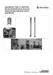
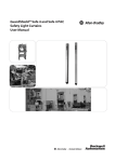
GuardShield™ Micro 400
Safety Light Curtains
User Manual
R
Important User Information
Because of the variety of uses for the products described in this publication, those responsible for the
application and use of this control equipment must satisfy themselves that all necessary steps have been
taken to assure that each application and use meets all performance and safety requirements, including
any applicable laws, regulations, codes and standards.
The illustrations, charts, sample programs and layout examples shown in the guide are intended solely for
purposes of example. Since there are many variables and requirements associated with any particular
installation, Rockwell Automation does not assume responsibility or liability (to include intellectual property
liability) for actual use based upon the examples shown in this publication.
Rockwell Automation publication SGI-1.1, Safety Guidelines for the Application, Installation and
Maintenance of Solid-State Control (available from your local Rockwell Automation sales office), describes
some important differences between solid-state equipment and electromechanical devices that should be
taken into consideration when applying products such as those described in this publication.
Reproduction of the contents of this copyrighted publication, in whole or part, without written permission
of Rockwell Automation, is prohibited.
Throughout this manual we use notes to make you aware of safety considerations:
WARNING
IMPORTANT
ATTENTION
Identifies information about practices or circumstances that can cause an explosion in
a hazardous environment, which may lead to personal injury or death, property
damage, or economic loss.
Identifies information that is critical for successful application and understanding of
the product.
Identifies information about practices or circumstances that can lead to personal
injury or death, property damage, or economic loss. Attentions help you identify a
hazard, avoid a hazard, and recognize the consequences.
SHOCK HAZARD
Labels may be on or inside the equipment (for example, drive or motor) to alert people
that dangerous voltage may be present.
BURN HAZARD
Labels may be on or inside the equipment (for example, drive or motor) to alert people
that surfaces may reach dangerous temperatures.
It is recommended that you save this user manual for future use.
GuardShield™ Micro 400 Safety Light Curtain User Manual
Conditions required for proper use of the
GuardShield Micro 400 Safety Light Curtain
Please make sure you read and understand these requirements before you select and install the
GuardShield Micro 400 safety light curtain. GuardShield safety light curtains are point of operation
and perimeter access safeguarding devices. These safety light curtains are intended to be used to
to provide point of operation and perimeter access safeguarding of personnel on a variety of
machinery.
The GuardShield Micro 400 family of safety light curtains are general purpose presence sensing
devices which are designed to protect personnel working on or near machinery.
The installation of GuardShield Micro 400 safety light curtains must comply with all applicable
federal, state, and local rules, regulations, and codes.
It is the responsibility of the employer to properly install, operate and maintain the product as
well as the machinery on which the GuardShield Micro 400 presence sensing device is installed.
GuardShield Micro 400 safety light curtains must be properly installed by qualified personnel.
GuardShield Micro 400 safety light curtains are presence sensing devices and will not protect
personnel from heat, chemicals, or flying parts. They are intended to signal a stop of hazardous
machine motion when the sensing field is broken.
GuardShield Micro 400 safety light curtains can only be used on machinery which can be stopped
anywhere in its stroke or cycle.
GuardShield Micro 400 safety light curtains should never be used on full revolution clutched
machinery.
The effectiveness of the GuardShield Micro 400 safety light curtains depends upon the integrity
of the machine control circuit. The machinery on which the GuardShield Micro 400 presence
sensing device is installed should have control circuitry that is fail safe in design.
All stopping mechanisms for the machinery should be inspected regularly to ensure proper
operation. The protected machinery must have a consistent reliable and repeatable stopping
time.
ATTENTION
Failure to read and follow these instructions can lead to misapplication or
misuse of the GuardShield Micro 400 safety light curtains, resulting in personal
injury and damage to equipment.
Original instructions
R
1
GuardShield™ Micro 400 Safety Light Curtain User Manual
Table of Contents
Product Label. . . . . . . . . . . . . . . . . . . . . . . . . . . . . . . . . . . . 19
Introduction. . . . . . . . . . . . . . . . . . . . . . . . . . . . . . . . . . . . . . .3
Important Requirements . . . . . . . . . . . . . . . . . . . . . . . . . . .4
Safety Precautions . . . . . . . . . . . . . . . . . . . . . . . . . . . . . . . . .4
Principles for Safe Use and Symbols Used . . . . . . . . . . . . . . . . . . . . . . 4
Specialist Personnel . . . . . . . . . . . . . . . . . . . . . . . . . . . . . . .4
Range of Uses of the Device . . . . . . . . . . . . . . . . . . . . . . . .4
Proper Use . . . . . . . . . . . . . . . . . . . . . . . . . . . . . . . . . . . . . . . . . . . . . . . . . . 5
General Protective Notes and Protective Measures . . . . . . . . . . . . . . 5
Product Description. . . . . . . . . . . . . . . . . . . . . . . . . . . . . . . .5
Special Features . . . . . . . . . . . . . . . . . . . . . . . . . . . . . . . . . . .5
Technical Specifications . . . . . . . . . . . . . . . . . . . . . . . . . . . . . . . . . . . . . 20
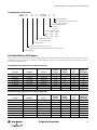
Catalog Number Configuration. . . . . . . . . . . . . . . . . . . . . . . . . . . . . . 21
GuardShield Micro 400 Products . . . . . . . . . . . . . . . . . . 21
Standard . . . . . . . . . . . . . . . . . . . . . . . . . . . . . . . . . . . . . . . . . . . . . . . . . . . 21
Cascades . . . . . . . . . . . . . . . . . . . . . . . . . . . . . . . . . . . . . . . . . . . . . . . . . . . 22
IP69K . . . . . . . . . . . . . . . . . . . . . . . . . . . . . . . . . . . . . . . . . . . . . . . . . . . . . 22
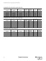
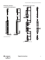
Dimensions. . . . . . . . . . . . . . . . . . . . . . . . . . . . . . . . . . . . . . 23
GuardShield Micro 400 Standard . . . . . . . . . . . . . . . . . . . . . . . . . . . . 23
GuardShield Micro 400 Cascades . . . . . . . . . . . . . . . . . . . . . . . . . . . . 23
GuardShield Micro 400 IP69K . . . . . . . . . . . . . . . . . . . . . . . . . . . . . . 24
Accessories . . . . . . . . . . . . . . . . . . . . . . . . . . . . . . . . . . . . . . 24
Certificate . . . . . . . . . . . . . . . . . . . . . . . . . . . . . . . . . . . . . . . 32
Principles of Operation. . . . . . . . . . . . . . . . . . . . . . . . . . . . .5
EC Declaration of Conformity . . . . . . . . . . . . . . . . . . . . . . . . . . . . . . 32
The GuardShield Light Curtain. . . . . . . . . . . . . . . . . . . . . .6
Appendix . . . . . . . . . . . . . . . . . . . . . . . . . . . . . . . . . . . . . . . 27
Cascading . . . . . . . . . . . . . . . . . . . . . . . . . . . . . . . . . . . . . . . . .6
GuardShield Micro 400 Special Safety Light Curtain Systems . .
Systems with Reinforced Profiles . . . . . . . . . . . . . . . . . . . . . . . . . . . . .
Perimeter Systems (PAC). . . . . . . . . . . . . . . . . . . . . . . . . . . . . . . . . . . .
Special Patchcords . . . . . . . . . . . . . . . . . . . . . . . . . . . . . . . . . . . . . . . . . .
Special Systems . . . . . . . . . . . . . . . . . . . . . . . . . . . . . . . . . . . . . . . . . . . . .
Examples of Range of Use . . . . . . . . . . . . . . . . . . . . . . . . . .6
Safety Functions . . . . . . . . . . . . . . . . . . . . . . . . . . . . . . . . . . .7
Response Time . . . . . . . . . . . . . . . . . . . . . . . . . . . . . . . . . . . .7
Blanking . . . . . . . . . . . . . . . . . . . . . . . . . . . . . . . . . . . . . . . . . .7
Determining the Safety Distance. . . . . . . . . . . . . . . . . . . .8
US Safety Distance Formula . . . . . . . . . . . . . . . . . . . . . . . . . . . . . . . . . . 8
OSHA Safety Distance Calculation Formula . . . . . . . . . . . . . . . . . . . 8
The ANSI Safety Distance Formula . . . . . . . . . . . . . . . . . . . . . . . . . . . 8
European Safety Distance Formula . . . . . . . . . . . . . . . . . . . . . . . . . . . . 9
Minimum Distance from Reflecting Surfaces . . . . . . . . . . . . . . . . . . . 9
Installation and Mounting . . . . . . . . . . . . . . . . . . . . . . . . 10
Correct Installation . . . . . . . . . . . . . . . . . . . . . . . . . . . . . . . . . . . . . . . . . 10
Incorrect Installation . . . . . . . . . . . . . . . . . . . . . . . . . . . . . . . . . . . . . . . . 10
Installation and Alignment Procedure . . . . . . . . . . . . . 11
Standard GuardShield Micro 400 . . . . . . . . . . . . . . . . . . . . . . . . . . . . 11
Multiple GuardShield Micro 400 . . . . . . . . . . . . . . . . . . . . . . . . . . . . . 11
Cascaded GuardShield Micro 400 . . . . . . . . . . . . . . . . . . . . . . . . . . . . 12
Mounting and Alignment of Cascading GuardShield. . . . . . . . . . . 13
Micro 400 IP69K . . . . . . . . . . . . . . . . . . . . . . . . . . . . . . . . . 13
Mounting Brackets. . . . . . . . . . . . . . . . . . . . . . . . . . . . . . . 13
Electrical Installation. . . . . . . . . . . . . . . . . . . . . . . . . . . . . 14
Connections. . . . . . . . . . . . . . . . . . . . . . . . . . . . . . . . . . . . . . . . . . . . . . . . 14
External test signal . . . . . . . . . . . . . . . . . . . . . . . . . . . . . . . . . . . . . . 16
Power supply . . . . . . . . . . . . . . . . . . . . . . . . . . . . . . . . . . . . . . . . . . . 16
Bringing into operation. . . . . . . . . . . . . . . . . . . . . . . . . . . . . . . . . . 16
Outputs . . . . . . . . . . . . . . . . . . . . . . . . . . . . . . . . . . . . . . . . . . . . . . . . 16
27
27
28
28
28
This manual covers the operation and installation
of the:
• GuardShield Micro 400 POC,
• GuardShield Micro 400 IP69K systems, and
• GuardShield Micro 400 special configurations in the appendix
IMPORTANT
Save these instructions for use at a future
time.
Generally recognized technical regulations and quality
assurance system ISO 9000 are carefully applied during
the development and production of Allen-Bradley/
Guardmaster products.
This technical description must be followed when
installing and commissioning the GuardShield Micro 400.
Inspection and commissioning must be carried out by a
qualified person.
Rockwell Automation reserves the right to make changes or revisions to
the material contained in this publication and cannot be held liable for
incidental or consequential damages resulting from the furnishing,
performance or use of this material.
Trouble Shooting . . . . . . . . . . . . . . . . . . . . . . . . . . . . . . . . 16
Corrective Steps . . . . . . . . . . . . . . . . . . . . . . . . . . . . . . . . . . . . . . . . . . . . 17
Checklist . . . . . . . . . . . . . . . . . . . . . . . . . . . . . . . . . . . . . . . . 18
Safety Instructions—Maintenance . . . . . . . . . . . . . . . . 18
Daily Inspection . . . . . . . . . . . . . . . . . . . . . . . . . . . . . . . . . . . . . . . . . . . . 18
Six-Month Inspection . . . . . . . . . . . . . . . . . . . . . . . . . . . . . . . . . . . . . . . 18
Cleaning . . . . . . . . . . . . . . . . . . . . . . . . . . . . . . . . . . . . . . . . . . . . . . . . . . . 18
2
Original instructions
R
GuardShield™ Micro 400 Safety Light Curtain User Manual
Introduction
The GuardShield Micro 400 is an economical three box (transmitter,
receiver and controller) Type 4 safety light curtain offered in a small
profile (15 x 20 mm (0.59 x 0.79 in.)) housing.
The protective heights are offered from 150…1200 mm in 150 mm
increments. The compact housing size allows the GuardShield
Micro 400 to be mounted in areas where standard safety light curtains
may not be able to be mounted due to space constraints. It is also possible
to recess the GuardShield Micro 400 transmitter and receiver into
machine frames.
Micro 400 System
The Micro 400 requires a dedicated controller, either an MSR41 which
has ON/OFF functionality or an MSR42 which offers advanced
functionality of fixed and floating blanking, manual restart and muting.
The MSR42 can also be used as a multi function safety module, allowing
the connection of additional safety light curtains, safety laser scanner —
any safety device with PNP type outputs.
The Micro 400 transmitter and receiver are offered with 8-pin M12
connectors at the end of 500 mm (20 in.) integrated cables. The
patchcords to connect the transmitter and receiver to the controller are
the same part number and are offered in a variety of lengths. These
patchcords are configured on one end with M12 connectors which mate
to the integrated pigtail connectors and RJ45 connectors on the opposite
end which plug into to the MSR 41 or MSR42 controllers.
Micro 400 Cascading
The GuardShield Micro 400 is also offered in a “cascadeable”
configuration. GuardShield Cascadeable Micro 400 safety light curtains
allow the interconnection of multiple segments of the Micro 400 safety
light curtain with a common pair of safety outputs. This cascadeable
configurability of the GuardShield Micro 400 reduces overall system
wiring and allows the GuardShield Micro 400 to be fitted into a variety
of applications where the safety distances for mounting the light curtain
may allow personnel to stand between the light curtain’s sensing field and
the hazard or where multiple-sided guarding is required and the use of
corner mirrors is not possible.
A GuardShield Cascadeable Micro 400 safety light curtain system is
comprised of one or two pair of Cascadeable Micro 400 light curtains as
well as a standard Micro 400 pair as the last segment pair in the cascaded
system.
GuardShield Micro 400 cascaded pairs are offered in both 14 mm and
30 mm resolutions in limited protected heights. It is possible to mix 14
mm and 30 mm resolution pairs in a Cascaded Micro 400 system.
connected in series making the complete system’s response time the sum
of each segment pair, plus the response time of the MSR41 or MSR42
and other safety devices in the stop circuit.
When connecting two cascadeable segments together, the resultant cable
length between segments is 1000 mm (40 in.).
If an additional length between segment pairs is required, Rockwell
offers an M12 to M12 patchcord in 1, 3, and 5 m (3.3, 9.8, and 16.3 ft)
lengths (445L-AC8PC1 or 445L-AC8PC3).
Note: The maximum Cascaded Micro 400 system length can not
exceed 10 m (32.8 ft) as measured between the RJ45 connection
at the MSR 41 or MSR 42 Controller to the last beam in the
standard Micro 400, including all cable lengths. The maximum
number of beams in a cascaded Micro 400 system can not exceed
255 beams.
Micro 400 Washdown Option
The GuardShield Micro 400 is offered with the transmitter and receiver
sealed in clear polycarbonate tubes with an environmental rating of
IP69K. These IP69K Micro 400 light curtains are factory sealed and are
ordered as pairs. They are offered in a 14 mm resolution in protected
heights of 300, 600, 900, and 1200 mm (11.8, 23.6, 35.4, and 47.2 in.).
The required MSR41 or MSR42 controllers maintain the IP20 rating
and must be mounted in a suitable enclosure.
The Micro 400 IP69K transmitter and receiver are both offered with
8-pin M12 connectors at the end of 500 mm (20 in.) integrated cables.
The patchcords to connect the transmitter and receiver to the controller
are the same part number and are offered in 3, 5, and 8m (9.8, 16.4, and
26.2 ft) lengths.
These patchcords are configured on one end with M12 connectors
which mate to the integrated pigtail connectors and RJ45 connectors on
the opposite end which plug into to the MSR42 or MSR41 controller.
Micro 400 Specials
In addition to the standard GuardShield Micro 400 configurations, the
GuardShield Micro 400 is also offered in special configurations as
described in the Appendix.
The GuardShield Micro 400 family of safety light curtains are general
purpose presence sensing devices, designed for use on hazardous
machinery providing point of operation (POC), as well as, perimeter
(PAC) detection.
IMPORTANT
Note: The standard GuardShield Micro 400 must always be the last
segment in a Cascaded Micro 400 system
A cascadeable pair of GuardShield Micro 400 light curtains has a
500 mm (20 in.) pigtail with a female M12 quick disconnect on the
bottom of the Micro 400 light curtain and a 500 mm (20 in.) pigtail with
a male M12 quick disconnect attached to the top of the Micro 400
transmitter and receiver.
The GuardShield Cascadeable Micro 400 system operates as a single
light curtain pair with a common set of OSSDs. Each segment pair is
Original instructions
R
These installation instructions are designed
to address the technical personnel of the
machine manufacturer and or the installer of
the safety system regarding the proper
mounting, configuration, electrical
installation, commissioning, operation and
maintenance of the GuardShield Micro 400
safety light curtain. These installation
instructions do not provide instruction for
the operation of machinery to which the
GuardShield Micro 400 safety light curtain is,
or will be, integrated. Only qualified
personnel should install this equipment.
3
GuardShield™ Micro 400 Safety Light Curtain User Manual
Important Requirements
There are a number of operating modes that can be configured with the
MSR42 controller. EDM, Start/Restart interlock, fixed and floating
blanking and muting are possible.
Safety Precautions
Principles for Safe Use and Symbols Used
The following instructions are preventive warnings to ensure the safe and
proper operation of the GuardShield Micro 400 light curtains. These
instructions are an essential part of the safety precautions and therefore
have to be observed at any time.
Throughout this manual we use the labels ATTENTION and
IMPORTANT to alert you to the following:
ATTENTION
Identifies information about practices or
circumstances that can lead to personal
injury or death, property damage, or
economic loss. Attentions help you identify a
hazard, avoid a hazard, and recognize the
consequences.
ATTENTION helps you
• Identify a hazard
• Avoid a hazard
• Recognize the consequences
Specialist Personnel
The GuardShield Micro 400 safety light curtain must be installed,
commissioned and serviced only by a qualified person. A qualified
person is defined as a person who:
• Has undergone the appropriate technical training
and
• Who has been instructed by the responsible machine operator in
the operation of the machine and the currently valid safety
guidelines
and
• Who has read and has ongoing access to these installation
instructions
IMPORTANT: Identifies information that is especially important for
successful application and understanding of the product.
IMPORTANT
The GuardShield Micro 400 must not be used
with machines that cannot be stopped
electrically in an emergency.
The safety distance between the GuardShield
Micro 400 and a dangerous machine
movement has to be maintained at all times.
Additional mechanical protective devices have to be
installed in a way that hazardous machine elements cannot
be reached without passing through the protective field.
The GuardShield Micro 400 has to be installed in a way that
operators can only access the hazard through the sensing
field of the Micro 400.
Improper installation can result in serious injury.
Never connect the outputs to +24V DC. If the outputs are
connected to +24V DC, they are in ON-state and cannot stop
hazardous spots at the machine/application.
Never expose the GuardShield Micro 400 to flammable or
explosive gases.
ATTENTION
The GuardShield Micro 400 requires a dedicated controller. The
MSR41 controller is used for on/off applications and the MSR42 can
also be used as a multi-functional safety module, allowing the connection
of additional safety light curtains, safety laser scanner, or any safety
device with two Output Signal Switch Devices (OSSD) outputs, or two
contacts, such as E-Stops and enabling switches.
Identifies information that is critical for
successful appilcation and understanding of
the product.
Range of Uses of the Device
The GuardShield Micro 400 safety light curtain is classified as electrosensitive protective equipment (ESPE). It fulfills the requirements of a
Type 4 ESPE defined by IEC 61496-1 and CLC/TS 61496-2 and is,
therefore, allowed for use with controls in safety category Type 4 in
compliance with EN ISO 13849, SIL CL3 in accordance with EN62061
or up to PLe in accordance with EN ISO 13849.
These devices are suitable for:
• Point of operation protection (finger and hand protection)
• Hazardous area protection
Access to the hazardous point must be allowed only through the
protective field. The machine/system is not allowed to start as long as
personnel are within the hazardous area. Refer to the “Examples of
Range of Use” on page 6 for an illustration of the protection modes.
Depending on the application, mechanical protection devices may be
required in addition to the safety light curtain.
4
Original instructions
R
GuardShield™ Micro 400 Safety Light Curtain User Manual
POC:
• Other relevant health and safety regulations
The physical resolution of the GuardShield Micro 400 POC is
• 14 mm (0.55 in.) or
• 30 mm (1.18 in.).
The protective field height of standard GuardShield Micro 400 is
between 150 mm (5.91 in.) and 1200 mm (47.2 in.).
The maximum protective field width is 0…5 m (16.4 ft).
Cascadable Micro 400
The physical resolution of cascadable GuardShield Micro 400 POC is
• 14 mm (0.55 in.) or
• 30 mm (1.18 in.).
The protective field height of cascadable GuardShield Micro 400 is
between 300 mm (11.82 in.) and 1200 mm (47.2 in.). The maximum
protective field width is 0…5 m (16.4 ft).
Product Description
Micro 400 IP69K Option
The physical resolution of the GuardShield Micro 400 IP69K is 14 mm
(0.55 in.). The protective field height of GuardShield Micro 400 IP69K
is between 300 mm (11.8 in.) and 1200 mm (47.2 in.). The maximum
protective field width is 0…5 m (16.4 ft).
The Micro 400 IP69K option has the Micro 400 light curtains factory
sealed in polycarbonate enclosures.
The GuardShield Micro 400 require a controller to operate in
conjunction with one of the following safety controllers
• MSR41 ON/OFF functionality
• MSR42 multi-function module
Proper Use
The GuardShield Micro 400 safety light curtain must be used only as
defined in the “Range of Uses of the Device.” It must be used only by
qualified personnel and only on the machine where it has been installed
and initialized by qualified personnel.
If the device is used for any other purposes or modified in any way,
warranty claims against Allen-Bradley/Guardmaster shall become null
and void.
General Protective Notes and Protective Measures
IMPORTANT
Manufacturers and users of the machine with which the safety light
curtain is used are responsible for obtaining and observing all applicable
safety regulations and rules.
• The notices, in particular the test regulations of these installation
instructions (e.g. on use, mounting, installation or integration into
the existing machine controller) must be observed.
• The tests must be carried out by specialist personnel or specially
qualified and authorized personnel and must be recorded and
documented to ensure that the tests can be reconstructed and
retraced at any time.
• The installation instructions must be made available to the user of
the machine where the GuardShield Micro 400 safety light curtain
is installed. The machine operator is to be instructed in the use of
the device by specialist personnel and must be instructed to read
the installation instructions.
Safety Notes
Please observe the following items in order
to ensure the proper and safe use of the
GuardShield Micro 400 safety light curtain.
The national/international rules and regulations apply to the
installation, use and periodic technical inspections of the safety light
curtain, in particular:
• Machine Directive 2006/42/EC
• Low Voltage Directive 2006/95/EC
• Use of Work Directive (2009/104/EC)
• The work safety regulations/safety rules
This section provides information on the special features and properties
of the safety light curtain. It describes the structure and functions of the
unit, in particular the different operating modes.
Please read this section before mounting, installing and commissioning
the unit.
Special Features
•
•
•
•
•
•
Slim design 15 x 20 mm (0.59 x 0.79 in.)
Built in diagnostic LEDs
HW configurable with MSR41
HW and SW configurable with MSR42
M12 connector on 20 inch pigtails
Maintenance free and cost effective
Principle of Operation
The GuardShield Micro 400 safety light curtain consists of a nonmatched pair of optic units, i.e., transmitter and receiver with the same
protected height and resolution. The controller functionality of the
Micro 400 light curtains are through a separate control module.
• MSR41 ON/OFF functionality
• MSR42 multi-function module
The maximum distance between transmitter and receiver is referred to as
the protective field width or range. The protective field height is the
distance between the first and last beam in the device.
The transmitter emits sequential pulses of infrared light which are
received by the GuardShield Micro 400 receiver and processed by the
connected controller. The synchronization of the timing of the emission
and reception of infrared light pulses is accomplished by the connected
MSR controller.
The connected controller has safety outputs [Output Signal Switching
Devices (OSSDs)] and nonsafety auxiliary outputs. When the
GuardShield Micro 400 transmitter and receiver are properly connected
and aligned, the OSSDs of the connected controller are current sourcing
Original instructions
R
5
GuardShield™ Micro 400 Safety Light Curtain User Manual
+24V DC. Interruption of the sensing field causes the controller to
switch the sourced current OFF (0V DC).
Restoring the GuardShield Micro 400 sensing field, (in Guard only
configuration) causes all safety outputs (OSSDs) of the connected
controller to switch to the active high state (resume current sourcing
+24V DC).
IMPORTANT
Operating mode as manual or automatic
restart (reset), EDM (external device
monitoring), blanked beams or overriding of
the GuardShield Micro 400 are controlled
from the connected safety controller (e.g.
MSR42). For details see user manual of the
connected safety controller.
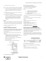
Patchcord
(2 meter max. length)
Last segment pair
can be cascading or
standard GuardShield pair
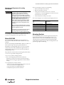
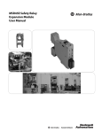
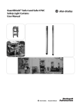
The GuardShield Light Curtain
Figure 2: Up to three GuardShield Micro 400 segments can be interconnected
The GuardShield Micro 400 safety light curtain consists of a transmitter
and a receiver.
Standard GuardShield Micro 400 cascading segments are offered in
protective heights from 300…1200 mm in both 14 mm and 30 mm
resolutions.
Transmitter
(white)
Receiver
(blue
marking)
A maximum of three GuardShield Micro 400 light curtains can be
interconnected (maximum two cascades plus one standard GuardShield
Micro 400). The maximum number of beams in a cascading system is
255 beams. The individual segments can have mixed resolutions, i.e.,
14 mm and 30 mm as long as the pairs have the same protective heights
and resolutions. The maximum cable length from the control unit to the
last beam can be 10 m.
Cascading segments cannot be used as standalone light curtain pairs.
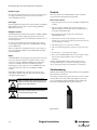
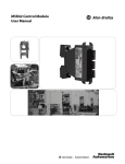
Figure 1: Components of the GuardShield Micro 400
The protective field is between the bottom of the top end cap and the
area above the status LEDs.
The width of the protective field is derived from the length of the light
path between transmitter and receiver and must not exceed the
maximum rated width of the protective field 0…5 m (0…16.4 ft).
Cascading
The GuardShield, Micro 400 POC is also available in cascading
segments which allow a number of GuardShield Micro 400 transmitters
and receivers to be interconnected. This product configurability allows
the GuardShield Micro 400 to protect multiple sides of a machine or
simply adds flexibility when positioning the GuardShield Micro 400 in
various applications.
6
However, if using multiple cascaded pairs or only one, the last pair in the
cascaded system must be a standard GuardShield Micro 400 light
curtain.
The following limitations need to be considered:
• A maximum of 255 light beams per controller
• 10 m maximum total length for light curtains, extension modules
and connection cable combined (Figure 14)
• Only a Rockwell patchcord (445L-AC8xxx) may be used between
the light curtains and the controller. A patchcord is required to
connect the M12 connector of the Micro 400 to either the
MSR41 or MSR42 controller. The patchcord has an
8-pin M12 on one end and an RJ45 connector on opposite end.
Examples of Range of Use
The GuardShield Micro 400 safety light curtain operates as a proper
protective device only if the following conditions are met:
• The control of the machine must be electrical.
• The controlled machine must be able to be stopped any where in
the machines stroke or cycle.
• The transmitter and receiver must be mounted such that access to
the hazard is only through the light curtain’s protective field.
• If used as an access device, the restart button must be located
outside the hazardous area such that it can not be operated by a
person working inside the hazardous area.
• The statutory and local rules and regulations must be observed
when installing and using the device.
Original instructions
R
GuardShield™ Micro 400 Safety Light Curtain User Manual
IMPORTANT
Additional measures may be necessary to
ensure that the ESPE does not fail to danger
when other forms of light radiation are
present in a particular application (i.e., use of
cableless control devices on cranes, radiation
from weld spatter or effects from strobe
lights).
IMPORTANT
Safety Functions
If a controller unit is reconfigured, a new
configuration control document must be
printed and has to be kept close to the
controller. Also the corresponding control
unit has to be marked with the provided
label.
The GuardShield Micro 400 safety light curtain offers a variety of
functions, which are integral to the system.
Operating modes, functions and features of the GuardShield system are
activated through HW or SW of the corresponding connected MSR41
or MSR42 controller. For details, please refer to the manual of the
attached controller.
IMPORTANT
The protective system must be tested for
proper operation after each and every
change to the configuration.
Response Time
The standard response time of the light curtain (see MSR42)is dependant
on the physical resolution and the protective height and is shown on the
product label. The actual response time depends on the connected
control unit and its configuration. The response time may be faster and
can be taken from the corresponding configuration control document,
created from the configuration software of the corresponding safety
controller (e.g., MSR42).
The total light curtain response time for cascaded light curtains is the
sum of the response times of each cascade. The declared response times
are worst case values.
A worst case response time is printed on the product label. e.g.:
19 ms
Response time tLC of the light curtain cascade
MSR42 Response time of the control unit including any connected
MSR45 relay modules
tN
Sum of response times tLC of all additional connected
GuardShield Micro 400 light curtain cascades
Example of the total response time of a cascaded light curtain:
Description
Length/Resolution
Response time
(tLC + tC + tN)
Cascade 1
1200/14 mm
41.9 ms + tC + tN
Cascade 2
300/14 mm
18.5 ms + tC + tN
Cascade 3
600/14 mm
26.3 ms + tC + tN
System
1200/14-300/14-600/14 mm
88.7 ms + tC
Table 1:
The response time printed on the product label reflects the double scan
mode of the MSR41 and MSR42 controller.
A detailed explanation, including the corresponding safety information,
for configuring a MSR42 controller module may be found in the
"Configuration Tool" program manual.
Parameters which may lead to an increased response time:
• Stop delay time
• Blanking
• Muting
• Using an MSR45E relay expansion module
IMPORTANT
When making changes to the configuration
of the GuardShield Micro 400 system, it is
necessary to recalculate the safety distance
and potentially relocate the GuardShield
Micro 400 light curtains at the proper
distance from the hazard.
Blanking
There are some industrial applications where material must be fed
through the protective field (e.g., textile machines or small assembly
machines). This movement of material through the GuardShield Micro
400’s sensing field in the standard safety mode would result in an
interruption and therefore bring the machine to an unwanted stop. To
avoid this it is possible to blank out certain beams. This operating mode
is generally known as “Fixed Blanking.” Blanking functionality is
available with the MSR42 controller and requires the optical interface
module to program this functionality.
IMPORTANT
The device can be operated in a fixed and/or
floating blanking mode if an MSR42
controller is used. The resolution will increase
according configuration control document.
The light curtain stick has to be clearly
labeled with the configured resolution.
With a MSR42 safety controller and an Optical Interface
(445L-AF6150) it is possible for authorized personnel to activate
different blanking modes. Blanking modes are broken down into the
following categories:
• Fixed blanking
• Floating blanking
Original instructions
R
The response time of the GuardShield Micro
400 light curtain system is dependent on the
operating mode of the connected safety
controller. With the help of an optical
interface (445L-AF6150) it is also possible, to
delay the response time of the connected
safety light curtain system, when the
GuardShield Micro 400 is connected to the
MSR42 controller.
7
GuardShield™ Micro 400 Safety Light Curtain User Manual
IMPORTANT
With the blanking function, the resolution
and the response time of the GuardShield
Micro 400 light curtain system will be
changed. If the "Blanking" function is
activated, a new, longer response time and a
new, larger resolution will be present, which
must be applied to the calculation of the
safety distance. The minimal safety distance
of the light curtain must always be adapted
to the actual operating mode. The
corresponding reaction time of a light
curtain without blanking is stated on the
label of each system. If blanking is
configured, the new reaction time, and the
new resolution, according to the
configuration control document must be
entered in the appropriate spaces on the
supplied label, and attached to the
GuardShield Micro 400 light curtain (see
Figure 3). The labels are provided with the
GuardShield Micro 400 mounting kit.
Fixed blanking
From beam................to beam.....
Floating blanking
Resolution................................mm
Reduced resolution
Reaction time...........................ms
Figure 3: Additional label for blanking. After configuring blanking, the label must be
attached and clearly visible on the receiver portion of the light curtain
IMPORTANT
Further information on "Blanking" may be
found in the “Configuration and Diagnostic
Tool” manual for the corresponding safety
controller (e.g. MSR42).
In the United States there are two formulas that are used to properly
calculate the safety distance. The first, the OSHA formula, is the
minimum requirement for the calculation of the safety distance. The
second formula, the one recommended by Rockwell Automation, is the
ANSI formula, which incorporates additional factors to be considered
when calculating the safety distance.
OSHA Safety Distance Calculation Formula
The OSHA safety distance formula as specified in CFR Subpart O
1910.217 is as follows:
Ds = 63 X TS
Ds
Safety Distance in inches
63
Is the OSHA recommended hand speed constant in inches per
second
Ts
Is the total stop time of all devices in the safety circuit, measured in
seconds. This value must include all components involved in
stopping the hazardous motion of the machinery. For a
mechanical power press it is the stopping time measured at
approximately the 90° position of the crankshaft rotation.
Note: The TS number must include the response times of all devices,
including the response time of the safety light curtain, the safety
light curtain controller (if used), the machine’s control circuit
and any other devices that react to stop the hazardous motion of
the machinery. Not including the response time of a device or
devices in the stop time calculation will result in insufficient
safety distance for the application. This may result in operator
injury.
IMPORTANT
Determining the Safety Distance
The light curtain must be mounted with proper safety distance
• From the point of danger
• From reflecting surfaces
The ANSI Safety Distance Formula
US Safety Distance Formula
IMPORTANT
The GuardShield Micro 400 safety light
curtains must be mounted at a sufficient
distance from the pinch point or point of
operation hazard to ensure that the machine
stops before a person’s finger, hand, arm(s),
or body reaches the hazard.
The ANSI safety distance formula, which is the Rockwell Automation
recommended formula, is as follows:
DS = K x (TS + TCS + Tr + Tbm) + Dpf
Ds
Minimum safety distance between the safeguarding device and the
nearest point of operation hazard, in inches.
K
Hand speed constant in inches per second. The ANSI standard
value is 63 inches per second when the operator begins reaching
toward the point of operation hazard from rest. NOTE: ANSI
B11.19 1990 E4.2.3.3.5 states “The value of the hand speed
constant, K, has been determined by various studies and although
these studies indicate speeds of 63 inches/second to over 100
inches/second, they are not conclusive determinations. The
employer should consider all factors, including the physical ability
of the operator, when determining the value of K to be used.”
Ts
Stop time of the machine tool measured at the final control
element.
This distance, referred to as the safety distance, must be properly
calculated prior to determining the safety light curtain’s protective height
and mounting the light curtains on the machine. Failure to properly
calculate this safety distance may result in operator injury.
IMPORTANT
8
Determining Stop Time: The measurement of
stopping time (Ts) must include the stopping
times of all devices in the stop circuit. Not
including all device and control system
elements when calculating Ts will result in an
inaccurate safety distance calculation.
Regardless of the calculated safety distance,
GuardShield Micro 400 safety light curtains
should never be mounted closer than six
inches from the point of operation or pinch
point hazard.
Original instructions
R
GuardShield™ Micro 400 Safety Light Curtain User Manual
Tcs
Response time of the control system.
How to Calculate the Safety Distance S
According to EN ISO 13855 and EN ISO 13857:
Note: Ts and Tcs are usually measured by a stop time measuring device.
Tr
Response time of the presence sensing device (safety light curtain)
and its interface (MSR4x and MSR45E). This value is generally
stated by the device manufacturer or it can be measured by the
user.
Tbm Additional time allowed for the brake monitor to compensate for
variations in normal stopping time.
Dpf Depth penetration factor. It is an added distance to allow for how
far into the protective field an object, such as a finger or hand, can
travel before being detected. Dpf is related to the safety light
curtain’s object sensitivity. Object sensitivity is the smallest
diameter object which will always be detected anywhere in the
sensing field.
-> First, calculate S using the following formula:
S = 2000 × T + 8 × (d – 14) [mm]
Where…
T = stopping/run-down time of the machine
+ response time of the protective device [s]
d = resolution of the light curtain [mm]
S = safety distance [mm]
The reach/approach speed is already included in the formula.
-> If the result S is <= 500 mm (19.6 in.), then use the determined value
as the safety distance.
-> If the result S is > 500 mm (19.6 in.), then recalculate S as follows:
S = 1600 × T + 8 × (d – 14) [mm]
Example:
Dpf (inches) = 3.4 × (Object Sensitivity – 0.276),
but not less than 0.
Stopping/run-down time of the machine = 290 ms
Response time = 30 ms
Resolution of the light curtain = 14 mm (0.55 in.)
T = 290 ms + 30 ms = 320 ms = 0.32 s
S = 2000 × 0.32 + 8 × (14 – 14) = 640 mm (25.1 in.)
S > 500 mm (19.6 in.) therefore:
S = 1600 × 0.32 + 8 × (14 – 14) = 512 mm (20.1 in.)
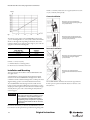
European Safety Distance Formula
Minimum Distance from Reflecting Surfaces
A safety distance must be maintained between the light curtain and the
point of danger. This safety distance ensures that the point of danger can
only be reached after the dangerous state of the machine has been
completely removed.
The infrared light from the transmitter may be reflected off of shiny
surfaces and be received by the system’s receiver. If this condition occurs,
it can result in an object not being detected when it enters the
GuardShield Micro 400 sensing field.
The safety distance as defined in EN ISO 13855 and EN ISO 13857
depends on:
• Stopping/run-down time of the machine or system. (The
stopping/run-down time is shown in the machine documentation
or must be determined by taking a measurement.)
• Response time of the protective device, e.g. GuardShield Micro
400 (for “Response Time” see page 7).
• Reach or approach speed.
• Resolution of the light curtain and/or beam separation.
All reflecting surfaces and objects (e.g. material bins) must therefore be
located at a minimum distance a from the protective field of the system.
The minimum distance a depends on the distance D between transmitter
and receiver.
Example:
In opto-electronic safeguarding, such as with a perpendicular safety light
curtain applications with object sensitivity (effective resolution) less than
2.5 inches, the Dpf can be approximated based on the following formula:
Safety distance S (Ds)
Distance D (meters)
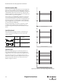
Figure 5: Minimum distance from reflecting surfaces
How to Determine the Minimum Distance from the Reflecting
Surfaces:
Protective field height
Point
of
danger
-> Determine the distance D [m] transmitter-receiver
-> Read the minimum distance a [mm] from the graph:
Distance to avoid standing behind
the safety curtain ≤75mm
Figure 4: Safety distance from the point of danger
Original instructions
R
9
GuardShield™ Micro 400 Safety Light Curtain User Manual
manual, i.e., machinery must be able to be stopped anywhere in its stroke
or cycle, consistently and repeatedly.
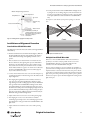
Correct Installation
Operators cannot reach hazardous
machine parts without passing through
the protective field.
Figure 6: Graph, minimum distance from reflecting surfaces
Operators must not step between the
protective field and hazardous machine
parts (by-pass prevention).
The effective aperture angle for the GuardShield Micro 400 system is
± 2.5° at a mounting distance of > 3.0 m (9.8 ft). Calculate the minimum
distance to reflecting surfaces depending on the distance between the
transmitter and the receiver, using an aperture angle of ± 2.5°, or take the
appropriate value from the following table:
Distance Between Transmitter and Receiver
(Range D) [m (ft)]
Minimum Distance
a [mm (in.)]
0.2…3.0 m (0.65…9.8 ft)
135 (5.31)
4.0 m (13.1 ft)
175 (6.88)
5.0 m (16.4 ft)
220 (8.66)
Incorrect Installation
Operators can reach hazardous machine
parts without passing through the
protective field.
Table 2: Table, minimum distance from reflecting surfaces
Formula: a = tan 2.5° x D [mm]
a = minimum distance to reflecting surfaces
D = distance between transmitter and receiver
Installation and Mounting
Operators can step between the
protective field and hazardous machine
parts.
This section describes the installation of the GuardShield Micro 400
safety light curtain.
A rigid and flat base, isolated against shock and vibration should be
selected to mount the GuardShield Micro 400 light curtain. This in
combination with the standard mounting bracket set will keep the initial
alignment during operation even in harsh industrial environments.
The GuardShield Micro 400 safety light curtain is suitable for most
benign operating environments (IP54). Proper safety distance as well as
adequate protective height must be observed. For the installation height
and safety distance, please refer to “Determining the Safety Distance”
section on page 8.
IMPORTANT
The GuardShield Micro 400 must be mounted at the proper distance
from the point of operation hazard. This distance is referred to as the
Safety Distance.
The installation of the GuardShield Micro 400
safety light curtain must be such that access
to the hazard is only possible through the
sensing field of the GuardShield. Auxiliary
safeguarding may be required in conjunction
with the GuardShield Micro 400 to meet this
requirement.
Determine if the machinery, on which the GuardShield Micro 400 is to
be mounted, meets the requirements as specified in the beginning of this
10
Original instructions
R
GuardShield™ Micro 400 Safety Light Curtain User Manual
Middle of Depth of Protective Field
Point of Operation
Safety Distance
Top of tool
Machine stop
time
8. Test the protective function of the GuardShield Micro 400 light curtain
by using the test rod, according to Figure 13. The insertion of this rod
into the protective field at any position has to lead to a protective field
interruption (illumination of the red LED in the GuardShield Micro
400).
Cycle power to assure that the system powers up and goes to the ON
state.
Protective Field Marking
Figure 7: Determining machine stopping time and safety distance
Receiver
To avoid the possibility of
standing between the protective
field and the point of operation,
the distance must be
maintained.
Transmitter
Incorrect
Bottom of tool
Standard GuardShield Micro 400
Receiver
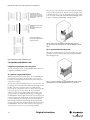
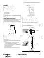
Installation and Alignment Procedure
Transmitter
Correct
The alignment procedure can be made easier with the use of integrated indicator
LEDs (Table 1).
1. Mount the transmitter and receiver with the brackets (Figure 9). Make sure
that the longitudinal axis of both are oriented parallel to each other. For a
vertical or horizontal mounting a level might help to find the correct
position.
2. Take care that the receiver and transmitter are oriented in the same
direction. This means, the beginning of the protective field which is
found next to the cable which leads to the safety controller, must be
located at the same end of the protective field. A reference would be
that the indicator LEDs are opposite one another. It is not allowed to
mount the GuardShield Micro 400 systems rotated 180° (Figure 8:
Layout of the transmitter/receiver).
3. Connect the transmitter and receiver to the controller and power up
according the description in the following section. The indicators will
help for alignment.
Figure 8: Layout of the transmitter/receiver
Multiple GuardShield Micro 400
When two or more GuardShield Micro 400s are mounted in close
proximity to one another, it may be possible for the receiver of one
GuardShield Micro 400 pair to receive infrared light from the
transmitter of another GuardShield Micro 400 pair.
There are various techniques to prevent or eliminate the possibility of
optical interference from light curtains mounted in the same plane. The
simplest method is to alternate transmitter and receiver pairs so that the
receiver from a second pair is facing away from the transmitter of another
light curtain pair in close proximity. It is also possible to place a physical
barrier between pairs to prevent the infrared light from reaching another
light curtain pair.
4. After aligning the longitudinal axis of the transmitter and receiver,
rotate the receiver along the longitudinal axis to find the receiving
angle. During rotation, the receiving angle is shown by the illumination
of the green LED in the GuardShield Micro 400 light curtain. If this
green LED is blinking, the amount of light detected by the receiver is
not sufficient for stable operation. After realigning the light curtain, the
protective field must be briefly interrupted. After removing the object
from the protective field, a sufficient intensity level is indicated by the
illumination of the green LED in the light curtain.
5. Adjust and mount the receiver at the center of this operating angle.
6. After aligning the receiver, rotate the transmitter to find the
transmitting angle. During rotation, the transmitting angle is shown
by the illumination of the green LED in the GuardShield Micro 400
light curtain.
7. Adjust and mount the transmitter at the center of this operating
angle.
Original instructions
R
11
GuardShield™ Micro 400 Safety Light Curtain User Manual
Transmitters emit in
opposite direction. Each
receiver receives only the
beams of the appropriate
transmitter.
The next step is to select the interconnect patchcords for the transmitter
and receiver. These patchcords are offered in a variety of lengths (“Table
6: Available cable types” on page 14). The final cascading segment which
is not connected to another pair of GuardShield Micro 400 light curtains
is equal to a standard GuardShield Micro 400 light curtain.
Transmitters emit in same
direction:
Optical (physical) barrier
necessary
Positioning of the light
curtain: Transmitters emit in
opposite direction.
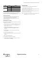
Figure 10: “L-shaped” two segment GuardShield Micro 400 cascading systems offer
protection when it is possible to stand between the vertical light curtain and the machine
hazard
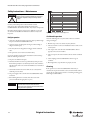
Three Segment GuardShield Cascading Systems
When the use of corner mirrors is not practical or possible, three-sided
guarding of a machine hazard is possible using cascading GuardShield
Micro 400 light curtains.
Figure 9: Multiple GuardShield Micro 400 alignment options
Cascaded GuardShield Micro 400
Configuration of Operating Modes in Cascading Systems
All of the operating modes of a cascaded GuardShield Micro 400 can be
configured at the MSR42 control unit.
Two Segment Cascading GuardShield Systems
When the safety distance calculation requires that a GuardShield pair is
vertically mounted at a distance that would allow a person to stand
between the vertical pair and the machine hazard, a means of detection
of that person is required.
There are a few methods of detecting the presence of a person who could
be standing in front of the machine hazard but inside of the light curtain;
installing a safety mat or safety laser scanner are possible solutions,
however, they are costly solutions as these are separate safety systems that
need to be integrated to the safety circuit. The most cost-effective
solution is to interconnect an additional light curtain in series to the
vertical pair. This is accomplished by first selecting a cascading pair of
GuardShield Micro 400 safety light curtains with a protective height and
resolution based upon the results of a risk assessment. It is then necessary
to select the horizontal protected height of the pair of GuardShield
Micro 400 light curtains. This pair should provide detection from the
vertical pair to the front of the machine hazard. In most cases this pair of
GuardShield Micro 400 can be 30 mm resolution as their purpose is to
detect the presence of a person, not a person’s fingers or hands.
12
Figure 11: Top and bottom mounting of three GuardShield Micro 400 segments is possible,
which will provide three-sided machine guarding without the use of corner mirrors
Original instructions
R
GuardShield™ Micro 400 Safety Light Curtain User Manual
Mounting and Alignment of Cascading
GuardShield
IMPORTANT
It helps to align the cascading segments in a
particular order. First connect the last
segment (segment with one connector)
closest to the control unit. Once the LED in
the edge is green; secure mounting brackets
of that pair. Next connect middle segment to
the last segment and connect to the
controller. When middle segment receiver
LED is green secure those brackets. Finally
connect the closest segment to the other
segments and connect all together to the
controller.
After every cleaning process please note the following:
• Remove water residues on the enclosure.
• Wipe the tubes with a clean cloth.
• Check position of transmitter and receiver to ensure that
excessively loose or excessively tight grip or movement to the back
by the safety device is not possible.
• Check safety function of the protective device
The connection plug has to be mounted away from high pressure water.
Protection Class (IEC 60529)
Tube:
Plug:
IP65, IP67, IP69K
IP65
Material: Connector and closure caps
POM (Polyoxymethylene)
Only the diagnosis LED of the first segment
displays the protective field status. The LEDs
of other segments stay off.
Plastic tube
PC (Polycarbonate)
Cable screw fitting
PA6 (Polyamide 6)
O-Rings (seals)
NBR (Nitril-Butadien-Rubber)
For aligning a cascaded system, the optical
interface module (see “Accessories” on
page 24) can be a valuable alignment help.
Mounting brackets
V2A [1.4301 (X5CrNi18-10)]
In a cascading system only the LEDs of the segment closest to the
controller are working. LEDs of other segments don’t work.
Micro 400 IP69K
The GuardShield Micro 400 IP69K meets the requirements of
Protection Classes IP65, IP66, IP67, IP68 and IP69K to IEC 60529
standards.
Table 3: Material specification
Mounting Brackets
The GuardShield Micro 400 is mounted using brackets which attach to
the side of both transmitter and receiver. It may be necessary to use
additional brackets to mount the GuardShield Micro 400 at a proper
safety distance from the machinery hazard. The backside of the light
curtain profile has continuous grooves to fix the mounting brackets at any
position along the light curtain housing.
The tubes surrounding the GuardShield Micro 400 have no influence on
either operation range or safety class as per IEC/EN 61496-1.
Mounting kits are provided which attach to the connection and end
module of the tube. The Micro 400 IP69K is supplied with the two
mounting brackets. Do not rotate end or connection cap (danger of
bending the light curtain).
The polycarbonate enclosure must be cleaned regularly and when dirty.
1. Do not use any powerful cleansing materials.
2. Do not use any abrasive cleansing materials.
3. Due to static charge dust particles remain attached to the
polycarbonate enclosure. You can alleviate this effect by using an
antistatic plastic cleansing agent applied with an antistatic cloth for
cleaning.
4. Clean polycarbonate enclosure as follows:
• Remove dirt on the enclosure using ample quantities of water. In
that way you will avoid scratching the surface.
• Then wipe off with a clean, slightly damp cloth.
• Finally, dry the plastic tube with a clean cloth.
Original instructions
R
13
GuardShield™ Micro 400 Safety Light Curtain User Manual
Further brackets may be obtained as an option, to offer the possibility of
mounting on the side or in the center:
39 (1.54)
445L-AF6143
Adjustable 180° bracket kit
(two per kit) supplied with
each pair
Description
Patchcord, PVC jacket, 1 m M12 to RJ45
Cat. No.
445L-AC8RJ1
Patchcord, PVC jacket, 2 m M12 to RJ45
445L-AC8RJ2
Patchcord, PVC jacket, 3 m M12 to RJ45
445L-AC8RJ3
Patchcord, PVC jacket, 5 m M12 to RJ45
445L-AC8RJ5
Patchcord, PVC jacket, 8 m M12 to RJ45
445L-AC8RJ8
Patchcord, PVC jacket, 1 m M12 to M12
445L-AC8PC1
Patchcord, PVC jacket, 3 m M12 to M12
445L-AC8PC3
Patchcord, PVC jacket, 5 m M12 to M12
445L-AC8PC5
32 (1.26)
Cable
28 (1.1)
M4
M4x16
3.3 25.5
(0.13) (1.0)
30
(1.18)
3
(0.18)
4.8
(0.19)
dia.
1.9 (0.08)
4.9 (0.19)
8.9 (0.35)
20
(0.79
445L-AF6145
Flat bracket kit (two per kit)
Two kits required per pair
12.7 (0.5)
9
(0.35)
24.95 (0.98)
35 (1.38)
445L-AF6149
Adjustable flat bracket (two
per kit)
Two kits required per pair
58 (2.28)
445L-AF6160
IP69K mounting bracket kit
37 (two kits per pair supplied
(1.46)
with each pair)
Table 4
17 (0.67)
Ferrite
32.5
(1.28)
150
(5.91)
31.5
(1.24)
17.5
(0.7)
6.3 (0.25) dia.
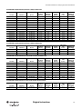
Table 6: Available cable types
Figure 12: RJ45 connector 8-pin connector [shielded cable], connection cable from MSR41 or
MSR42 control unit to the light curtain
Length, see table; tolerance 0/+50 mm
50.2
(1.98)
17
(0.67)
Dia.
15 (0.59)
Dia.
80
(3.15)
32.2
(1.27)
51.3
(2.02)
Figure 13: M12 connector (male) M12 8-pin connector (female) [shielded cable]
Patchcord M12 to M12 to extend connection cable or to use between
light curtain cascades.
Electrical Installation
Electrical Installation
Connections
The connection of a GuardShield Micro 400 to a machine controller
must occur using an MSR41 or MSR42 Series safety controller module.
Only prefabricated cable (445L-AC8xxx) provided by Rockwell
Automation may be used between the light curtain and controller
(Table 5).
The Micro 400 requires two patchcords, one for the transmitter and one
for the receiver. The M12 8-pin connector is used for connecting to the
light curtain, while the RJ45 connector is plugged to the controller. M12
to M12 patchcords are used for extending the cable, especially between
cascades of the Micro 400 light curtain.
The connection of a GuardShield Micro 400 to a machine controller
must occur using an MSR41 or a MSR42 Series safety controller module.
Power supply, inputs, safety outputs and status outputs are connected to
the terminal block of the MSR41, MSR42 controller or a MSR45E.
The interfacing of the light curtain with the machine control has to be
control reliable, i.e. a correct interface with a safety PLC or safety relays
with positive guided relay contacts.
ATTENTION
The connection cables are offered with color coded rings attached to
each cable. Remove one color ring from the cable as necessary. The
following color code is defined:
The safety devices and the interconnection to
the machinery have to comply with the basic
safety requirements as mentioned in the
current regulations and standards.
Direct interfacing of a safety light curtain to
machine control that does not meet the
necessary safety integrity level, i.e., use of
general purpose PLCs or general purpose
relays may result in injury to personnel.
White – Transmitter (Tx)
Blue – Receiver (Rx)
14
Original instructions
R
GuardShield™ Micro 400 Safety Light Curtain User Manual
24V DC
Transmitter
Receiver
Start
Lamp
GPIO4
Blue
GPIO3
GPIO2
GPIO1
OSSD2
OSSD1
Info2
K1
Info1
K2
In2
In1
0V
White
24 V
K2
K1
M
0V DC
Figure 15: Wiring diagram for connection of MSR42 to contactors
+24V DC
RJ-45
LAMP
Start
GPIO4
Blue
GPIO3
Micro 400
.
.
GPIO1
.
.
OSSD2
.
.
.
.
.
.
13
.
.
14
OSSD1
MSR42
GPIO2
INFO2
INFO1
K3
K4
IN2
MSR45E
Emitter
Receiver
Ribbon Cable for Extender
L1 L2 L3
K4
IN1
0V/GND
White
+24V
23
24
K3
RJ-45
GND = 0V
M
Figure 16: Wiring Diagram for connection to MSR45E Expansion Module and external contactor using start release
Original instructions
R
15
GuardShield™ Micro 400 Safety Light Curtain User Manual
External test signal
Checklist
In case the risk analysis of the application requires an external test signal
(according to EN 13849-1) please refer to the user manual of the
connected MSR42 control unit.
Before the initiation of the GuardShield Micro 400 the responsible
person should work through the following checklist.
Cable check prior to initiation:
Power supply
The power supply and the evaluation of the protective field of a GuardShield
Micro 400 light curtain can only be carried out through a MSR41 or
MSR42 Series control unit.
Bringing into operation
The transmitter and receiver units must be connected to a MSR41 or MSR42
safety control unit. Then the supply voltage may be connected to the
control unit. After power-up, there is an automatic self test (duration < 5 s) of
all system components.
In case the protective field is free and the transmitter and receiver are
correctly aligned, the green LEDs on the GuardShield Micro 400 light
curtains will illuminate.
If after a successful power-up the light curtain detects an interruption of
the protection field, the red LEDs on the GuardShield Micro 400 light
curtains will illuminate.
Outputs
A GuardShield Micro 400 safety light curtain pair is always connected to
a safety controller. Every connection to a machine controller or a safety
circuit is done through an MSR41 or MSR42 safety controller, which
provides two redundant semiconductor OSSD (Output Signal
Switching Device) safety outputs. One or more MSR45E safety relay
expansion modules can be connected to the MSR41 or MSR42
controller.
Each MSR41 or MSR42 safety controller also provides two status
outputs (Info1 and Info2). These may only be connected to the machine
controller for information purposes.
ATTENTION
ATTENTION
The status outputs (Info1 and Info2) of the
MSR41 or MSR42 safety control units are not
safety related. They may not be used within the
safety circuit of the machine.
1. The power supply is solely connected to the MSR41 or MSR42 safety
controller.
2. The power supply is a 24V DC device, that must comply to all
applicable standards of the Machinery Directive 2006/42/EC, and
the product standard (IEC 61496).
3. Proper polarity of the power supply at the controller of the
GuardShield Micro 400.
4. The transmitter connection cable is properly connected to the
transmitter, the receiver connection cable is properly connected to the
receiver. All plugs are connected.
5. The OSSD outputs are not connected to +24V DC.
6. The connected switching elements (load) are not connected to 24V
DC.
7. No connection to a conventional power supply.
8. If two or more GuardShield Micro 400s are to be used, make sure that
each system is properly installed, in order to avoid optical
interference.
Switch the GuardShield Micro 400 on and check its function by
observing the following: two seconds after switching on, the system
starts to work properly if the protection field is free of obstructions
Troubleshooting
With the help of two LEDs, system conditions and faults of the GuardShield
Micro 400 systems are indicated.
A red and a green LED are integrated in the end-cap connection module
of each profile (near the cable), which clearly signals the status of the
protective field. With the help of the LED display, system conditions and
faults of the GuardShield Micro 400 systems are indicated.
Prior to powering up the GuardShield Micro
400 system, the responsible person should
review the following Checklist.
Figure 17: Indicators
16
Original instructions
R
GuardShield™ Micro 400 Safety Light Curtain User Manual
LED
Green
Red
Color
Corrective steps
Meaning
On
Protective field free
1. Examine connections, cables and plugs of transmitter and receiver.
Flashing
Intensity inadequate
Off
Protective field free
2. Turn the supply voltage off and on again.
On
Light curtain interrupted
Flashing
Error (lock out condition)
With the help of the optical interface, it is possible to display the lock out
information at a Laptop per USB interface.
If the LED of the safety light curtain is still blinking red, please contact
Rockwell Automation technical support.
Table 7: LED meanings
The conditions signaled by the LEDs can also be obtained from the
status outputs of the connected MSR41 or MSR42 Series safety control
module (see user manual of the corresponding control unit).
Note: In cascaded systems only the LED in the first safety light curtain
will illuminate (closest to the safety controller).
Red LED continuously shining:
Check the alignment if the LED of the GuardShield Micro 400 is
continuously red. With the help of the optical interface
(445L-AF6150) it is possible to display individual beam status at a
Laptop per USB interface.
Red LED blinking (lock-out condition):
If the red LED of the GuardShield Micro 400 is blinking, the following
conditions can cause the fault:
1. Inadequate supply voltage to the MSR41 or MSR42 safety controller.
2. Transmitter and/or receiver cables not correctly plugged into the
MSR41 or MSR42 controller.
3. Transmitter and receiver light curtains are connected to the incorrect
locations in the controller (transmitter plugged into receiver
connection).
4. Incorrect assembly in case of cascaded systems (transmitter and
receiver mixed).
5. Cable connector makes poor contact.
6. Error in the EDM feedback channel at the safety control (only in case
of EDM).
7. Short circuit at the OSSD outputs.
8. Foreign light source affecting the receiving unit.
9. Blanking configured and wrong light curtain length or resolution
connected (only in case of blanking).
Original instructions
R
17
GuardShield™ Micro 400 Safety Light Curtain User Manual
ATTENTION
Never operate the GuardShield Micro 400
before carrying out the following inspection.
Improper inspection may lead to operator
injury.
For safety reasons all inspection results should be recorded.
Transmitter
Safety Instructions—Maintenance
Only persons, who clearly understand the functioning of the
GuardShield Micro 400 and of the machine, may carry out an inspection.
If installer, planning engineer and operator are different people, make
sure that the user has sufficient information available to carry out the
inspection.
Figure 18: Proper testing of protective field using test rod
Six-Month Inspection
Daily Inspection
1. Approach to hazardous machine parts must only be possible through
the protective field of GuardShield Micro 400.
2. Operators cannot step through the sensing area while working on
dangerous machine parts.
3. The safety distance of the application is bigger than the calculated
value.
4. The optic front cover is neither scratched nor dirty.
Operate the machine and check, if the hazardous movement will stop
under the following circumstances.
Check the following items every six months or whenever a machine
setting was changed.
1. Machine stops or does not obstruct any safety function.
2. The latest machine or connection modifications have no effect on the
control system.
3. The outputs of the controller of the GuardShield Micro 400 are
properly connected to the machine.
4. The total response time of the machine is shorter than the calculated
value.
5. Cables and plugs of the GuardShield Micro 400 are in good
condition.
5. The protective field is interrupted.
6. Hazardous machine movement stops immediately, if the protective
field is interrupted by the test rod directly in front of the transmitter,
directly in front of the receiver and in the middle between transmitter
and receiver.
7. No hazardous machine movement while the test rod is anywhere
within the protective field.
8. The power supply of the controller of the GuardShield Micro 400 is
turned off.
6. Mounting brackets, caps and cables are properly secured.
Cleaning
If the optic front cover of the GuardShield Micro 400 is dirty or
scratched, the outputs turn off. Take a clean, soft cloth and rub without
pressure. Do not apply aggressive, abrasive or scratching cleansing agents,
which might attack the surface.
9. If the blanking function is activated, check all sections of the
protective field with the appropriate test piece.
IMPORTANT
18
If any of the above conditions do not result in
the hazardous motion of the machine
ceasing, do not allow the protected machine
to be placed in operation.
Original instructions
R
GuardShield™ Micro 400 Safety Light Curtain User Manual
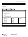
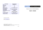
Product Label
GuardShieldTM
Micro400 Tx
Cat No. 445L-T4C0300FP Ser A Rev A
3T8LA5AA
AOPD 24XE
106 402 S400S-KEF5N-LF6-V-AABA00199 ID: 2504-2504
Operat. range: 0 to 5m
Protect. height: 300mm
Product of Resolut. 14 mm
Encl. Rating: IP54
Switzerland Response time: < 19 ms +tc + tn
HW: V1.15 Type 4
Figure 19
Date Code
AABCCDEE
AA = Production place (AL=Mexico, 3T= Switzerland)
B
= Year
CC = Day (LA = 001, LB = 002, …)
D = Internal RA product code
4
= GS Safe 4 System
5
= GS Safe 4 Tx
6
= GS Safe 4 Rx
EE = Counter (AA=001, AB=002, …)
Example: 3T8LA5AA:
AA = 3T = Produced in Switzerland
B
= 8
= Year 2008
CC = LA = Day 001
D = 5
= Transmitter
EE = AA = 001
Explanation of terminology
Rx
Receiver
Tx
Emitter
Cat No
Catalog Number
Ser
Series number
Rev
Revision number
HW
Hardware version
AOPD Type
Active optoelectronic protective equipment type 4 based on IEC
61496-1, -2
Type 4
type 4 based on IEC 61496-1, -2
3T8LA5AA
Date Code
Operating range
Maximum operating range
Protective height
Protective height
Resolution
Resolution for the protective device ("without blanking")
Enclosure Rating
IP – enclosure rating
Response time
(no blanking)
Response time (see MSR42) for the protective device. See Response
Time on page 7.
19 ms Response time tLC of the light curtain cascade
tc
Response time of the control unit including any connected
relay modules
tN
Sum of response times tLC of all additional connected
GuardShield Micro 400 light curtain cascades
Table 8
Original instructions
R
19
GuardShield™ Micro 400 Safety Light Curtain User Manual
Technical Specifications
Safety Ratings
Standards
IEC/EN61496 Parts 1 and 2, UL61496 Parts 1 and 2, UL1998
Safety Classification
Type 4 per IEC/EN61496. Category 4 device per EN 954-1, SIL 3 per IEC 61508, PLe per EN/ISO 13849-1
Probability of a dangerous failure per hour PFH
6.0 E-9 1/h MSR42 or MSR41 and MSR45E
4.0 E-9 1/h Micro 400
Certifications
cULus Listed, TÜV, CE Marked for all applicable directives
Outputs
Micro 400 Outputs
Data output to controller (MSR41 or MSR42)
MSR41/MSR42 Outputs
Two 400 mA OSSD
Non-Safety Outputs
Auxiliary outputs from MSR41 or MSR42 controller—2 configurable 100 mA, outputs
Switching Current @ Voltage, Max.
400 mA @ 24V DC
Operating Characteristics
Response Time
14 mm: 12…42 ms, varies by protective height and resolution, protect. height 150-1200 mm
30 mm; 11…23 ms, varies by protective height and resolution, protect. height 150-1200 mm
Indicator LEDs
ON -State, OFF-State, Intensity, Lockout
Protected Height [mm (in.)]
150…1200 (5.9 …47.2) in 150 mm increments
Resolution [mm (in.)]
14 (0.55), 30 (1.18) or PAC (Perimeter)
Scanning
Range/Resolution
14 mm (0.55 in.) resolution: 0…5 m (16.4 ft)
30 mm (1.18 in.) resolution: 0…5 m (16.4 ft)
Synchronization
Electrical through MSR41 or MSR42
Wave length
940 nm
Time for self check when switching on Usp
<5s
Environmental
Enclosure Type Rating
Micro 400 is IP54;
Micro 400 IP69K is IP65, IP66, IP67, IP68, IP69K, Plug: IP65
Relative Humidity
15…95% (noncondensing)
Operating Temperature
0…55 °C (14…131 °F)
Storage Temperature
-20…70 °C (4…158 °F)
Vibration
IEC 60068-2-6; Frequency 10…55 Hz; Amplitude 0.35 mm (0.01 in.)
Shock
IEC 60068-2-29; Acceleration 10 g, pulse duration 16 ms 10…55 Hz;
Amplitude 0.35 mm (0.01 in.)
Power Supply
Input power from MSR41 or MSR42 controller
Input Power, Max.
24V DC ±15% (MSR41 or MSR42 controller)
Maximum Residual Ripple
5% of Vss
Power Consumption
0.07 A max. (no load)
Equipment Class
III (VDE 0106 part 100)
EMC
IEC 61496 part 1
Physical Characteristics
Max. number of beams
255
Standard mounting
180° adjustable mounting brackets supplied (two sets 445L-AF6143)
Weight
Varies by protective height
Housing Cross Section
15 mm x 20 mm (0.59…0.79 in.) profile slim30 mm x 40 mm (1.18.1.57 in.) profile reinforced
Optical window
Polycarbonate
Enclosure treatment
Polyester powder coated, silicon free
Connection Type
Transmitter/receiver: 8-pin M12 micro QD
Cable Length
1, 2, 3, 5, and 8 m (3.3, 6.6, 9.8, 16.4, and 26.2 ft) cable M12 to RJ45 for MSR41 or MSR42.
Max. total system length can not exceed 10 m (32.8 ft).
Patchcords
1, 3 and 5 m (3.3, 9.8 and 16.4ft) M12 to M12 patchcords.
Total system length cannot exceed 10 m (32.8 ft) including protective height of Micro 400, integrated cables and patchcords from M12
connector to MSR41 or MSR42.
20
Original instructions
R
GuardShield™ Micro 400 Safety Light Curtain User Manual
Catalog Number Configurator
445L- P
4
C
0150 F
P
Connector Option
P = Pigtail with micro QD connector
D = M12, 8-pin QD
Environmental Rating:
F = IP54
K = IP69K
Protective Height (mm)
0450 0900
0150 0600 1050
0300 0750 1200
C = 14 mm resolution
E = 30 mm resolution
Category Type 4
P = Pair; T = Transmitter; R = Receiver
C= Cascade; G = Cascade transmitter; E = Cascade receiver
Bulletin Number
GuardShield Micro 400 Products
The response times (*) are maximum values with no blanking configured. If blanking is configured in the Micro 400 controller, the response time values
could be higher. The times depend on the controller type and the configuration. The real response time may be faster. Please obtain the exact time from
the software "Configuration Tool."
GuardShield Micro 400, Standard, Profile 20 x 15 mm, Resolution 14 mm
Protection
Height A
[mm (in.)]
Max. response time
tLC
Weight per pair
(ms) *
[incl. packaging]
Sensor Pair
Transmitter
Receiver
Resolution
[mm (in.)]
445L-P4C0150FP
445L-T4C0150FP
445L-R4C0150FP
14 (0.55)
150
14.6 ms
0.8 kg
445L-P4C0300FP
445L-T4C0300FP
445L-R4C0300FP
14 (0.55)
300
18.5 ms
0.9 kg
445L-P4C0450FP
445L-T4C0450FP
445L-R4C0450FP
14 (0.55)
450
22.4 ms
0.9 kg
445L-P4C0600FP
445L-T4C0600FP
445L-R4C0600FP
14 (0.55)
600
26.3 ms
1.0 kg
445L-P4C0750FP
445L-T4C0750FP
445L-R4C0750FP
14 (0.55)
750
30.2 ms
1.1 kg
445L-P4C0900FP
445L-T4C0900FP
445L-R4C0900FP
14 (0.55)
900
34.1 ms
1.3 kg
445L-P4C1050FP
445L-T4C1050FP
445L-R4C1050FP
14 (0.55)
1050
38.0 ms
1.3 kg
445L-P4C1200FP
445L-T4C1200FP
445L-R4C1200FP
14 (0.55)
1200
41.9 ms
1.3 kg
Protection
Height A
[mm (in.)]
GuardShield Micro 400, Standard, Profile 20 x 15 mm, Resolution 30 mm
Max. response time
tLC
Weight per pair
(ms) *
[incl. packaging]
Sensor Pair
Transmitter
Receiver
Resolution
[mm (in.)]
445L-P4E0150FP
445L-T4E0150FP
445L-R4E0150FP
30 mm (1.18)
150
12.4 ms
0.8 kg
445L-P4E0300FP
445L-T4E0300FP
445L-R4E0300FP
30 mm (1.18)
300
13.9 ms
0.9 kg
445L-P4E0450FP
445L-T4E0450FP
445L-R4E0450FP
30 mm (1.18)
450
15.5 ms
0.9 kg
445L-P4E0600FP
445L-T4E0600FP
445L-R4E0600FP
30 mm (1.18)
600
17.0 ms
1.0 kg
445L-P4E0750FP
445L-T4E0750FP
445L-R4E0750FP
30 mm (1.18)
750
18.5 ms
1.1 kg
445L-P4E0900FP
445L-T4E0900FP
445L-R4E0900FP
30 mm (1.18)
900
20.2 ms
1.2 kg
445L-P4E1050FP
445L-T4E1050FP
445L-R4E1050FP
30 mm (1.18)
1050
21.7 ms
1.3 kg
445L-P4E1200FP
445L-T4E1200FP
445L-R4E1200FP
30 mm (1.18)
1200
23.3 ms
1.3 kg
Original instructions
R
21
GuardShield™ Micro 400 Safety Light Curtain User Manual
GuardShield Micro 400, Cascaded, Profile 20 x 15 mm, Resolution 14 mm
Protection
Height A
[mm (in.)]
Max. response time
tLC
Weight per pair
(ms) *
[incl. packaging]
Sensor Pair
Transmitter
Receiver
Resolution
[mm (in.)]
445L-C4C0150FP
445L-G4C0150FP
445L-F4C0150FP
14 (0.55)
150
14.6 ms
0.8 kg
445L-C4C0300FP
445L-G4C0300FP
445L-F4C0300FP
14 (0.55)
300
18.5 ms
0.9 kg
445L-C4C0450FP
445L-G4C0450FP
445L-F4C0450FP
14 (0.55)
450
22.4 ms
0.9 kg
445L-C4C0600FP
445L-G4C0600FP
445L-F4C0600FP
14 (0.55)
600
26.3 ms
1.0 kg
445L-C4C0900FP
445L-G4C0900FP
445L-F4C0900FP
14 (0.55)
900
34.1 ms
1.2 kg
445L-C4C1200FP
445L-G4C1200FP
445L-F4C1200FP
14 (0.55)
1200
41.9 ms
1.3 kg
Protection
Height A
[mm (in.)]
GuardShield Micro 400, Cascaded, Profile 20 x 15 mm, Resolution 30 mm
Max. response time
tLC
Weight per pair
(ms) *
[incl. packaging]
Sensor Pair
Transmitter
Receiver
Resolution
[mm (in.)]
445L-C4E0150FP
445L-G4E0150FP
445L-F4E0150FP
30 (1.18)
150 mm
12.4 ms
0.8 kg
445L-C4E0300FP
445L-G4E0300FP
445L-F4E0300FP
30 (1.18)
300 mm
13.9 ms
0.9 kg
445L-C4E0600FP
445L-G4E0600FP
445L-F4E0600FP
30 (1.18)
600 mm
17.0 ms
1.0 kg
445L-C4E0750FP
445L-G4E0750FP
445L-F4E0750FP
30 (1.18)
750 mm
18.5 ms
1.1 kg
445L-C4E0900FP
445L-G4E0900FP
445L-F4E0900FP
30 (1.18)
900 mm
20.2 ms
1.2 kg
445L-C4E1200FP
445L-G4E1200FP
445L-F4E1200FP
30 (1.18)
1200 mm
23.3 ms
1.3 kg
Receiver
Resolution
[mm (in.)]
Protection
Height A
[mm (in.)]
GuardShield Micro 400, IP69K, tube, Resolution 14 mm
Sensor Pair
22
Transmitter
Max. response time
tLC
Weight per pair
(ms) *
[incl. packaging]
445L-P4C0300KD
445L-T4C0300KD
445L-R4C0300KD
14 (0.55)
300
18.5 ms
0.7 kg
445L-P4C0600KD
445L-T4C0600KD
445L-R4C0600KD
14 (0.55)
600
26.3 ms
0.9 kg
445L-P4C0900KD
445L-T4C0900KD
445L-R4C0900KD
14 (0.55)
900
34.1 ms
1.1 kg
445L-P4C1200KD
445L-T4C1200KD
445L-R4C1200KD
14 (0.55)
1200
41.9 ms
1.3 kg
Original instructions
R
GuardShield™ Micro 400 Safety Light Curtain User Manual
Dimensions [mm (in.)]
GuardShield Micro 400 Cascades
GuardShield Micro 400 Standard
51.3
(2.02)
51.3
(2.02)
50
(1.97)
455
(17.91)
32.5
(1.28)
14.2
(0.56)
27.8
(1.09)
A - protection length according to table
A - protection length according to table
27.8
(1.09)
1.5
(0.06)
15.5
(0.61)
455
(17.91)
15.5
(0.61)
15.5
(0.61)
19.8
(0.78)
27.8
(1.09)
19.8
(0.78)
455
(17.91)
Figure 20: GuardShield Micro 400
51.3
(2.02)
15
(0.59)
Figure 21: GuardShield cascadable Micro 400
Original instructions
R
23
GuardShield™ Micro 400 Safety Light Curtain User Manual
GuardShield Micro 400 IP69K (Washdown)
System Cat No.
(incl. Mounting kit)
Protection zone height A
mm (inch)
System Length B [mm]
445L-P4C0300KD
300 (11.8)
374
445L-P4C0600KD
600 (23.6)
674
445L-P4C0900KD
900 (35.4)
974
445L-P4C1200KD
1200 (47.2)
1274
Ø 28.4
(1.12)
Table 9
18
(0.71)
500
(19.7)
System length B
38.50
(1.52)
58
(2.28)
29.5
(1.16)
27
(1.06)
Protection high A
17.5
(0.69)
Figure 22
Accessories
Required Safety Controller — Select One
Description
Mounting
Size
Cat. No.
35 mm DIN Rail
22.5 mm
440R-P221AGS
35 mm DIN Rail
22.5 mm
440R-P226AGS-NNR
MSR41 ON/OFF
MSR42 Multi-functional module
24
Original instructions
R
GuardShield™ Micro 400 Safety Light Curtain User Manual
Optional Safety Relay Expansion Module
Relay
Input Voltage
Reset
Outputs
Cat.No.
Supplied by MSR41 or MSR42
Determined by MSR41 or MSR42
2 N.O.
440-P4NANS
MSR45E
Safety Relay Expansion Module
Safety Relay Interface accessories for MSR41 or MSR42 Controllers
The MSR41 or MSR42 can have up to three MSR45E safety relays interconnected. Each module requires a ribbon cable connector to make the
interconnection. The table shows the cat. no. for each ribbon cable connector.
Description
Cat. No.
Ribbon cable – for one MSR45E
440R-ACABL1
Ribbon cable – for two MSR45Es
440R-ACABL2
Ribbon cable – for three MSR45Es
440R-ACABL3
Optical interface
Operation mode and parameters of the MSR42 controller may be changed using the configuration software which is available on www.ab.com and with
the optical interface 445L-AF6150. Programming of the MSR42 is only necessary for advanced operating modes (e.g. blanking, muting, etc.) or for
connection of additional devices (e.g., enabling switch, emergency stop button, etc.).
Description
Cat. No.
USB optical interface software configuration tool used to configure
the MSR42
Original instructions
R
445L-AF6150
25
GuardShield™ Micro 400 Safety Light Curtain User Manual
Optional accessories:
Description
Cat. No.
Adjustable 180° bracket kit (two per kit) supplied with each pair
445L-AF6143
Flat bracket kit (two per kit)
Two kits required per pair
445L-AF6145
Adjustable flat bracket (two per kit)
Two kits required per pair
445L-AF6149
IP69K mounting bracket kit (two kits per pair supplied with each
IP69K pair)
445L-AF6160
Mirror 440L-AM075
Corner Mirror for Multi-Sided Guarding
8 x 13
Specially constructed glass mirrors for 2- and 3-sided safeguarding
applications.
50 (1.96)
Note: Each mirror reduces maximum scan range by 10% per mirror.
Each corner mirror supplied with two end-cap mounting
brackets:
73 (2.87)
B
L
Protected Height
[mm (in.)]
A
Ls
Narrow Mirror
Short-Range
0…4 m
(0…13.1ft)
Mirror height
[(mm (in.)]
Cat. No.
150 (5.9) / 300 (11.8)
300 (11.8)
440L-AM0750300
450 (17.7)
450 (17.7)
440L-AM0750450
600 (23.6)
600 (23.6)
440L-AM0750600
750 (29.5)
750 (29.5)
440L-AM0750750
900 (35.4)
900 (35.4)
440L-AM0750900
1050 (41.3)
1050 (41.3
440L-AM0751050
1200 (47.2)
1200 (47.2)
440L-AM0751200
10.5
(0.41)
A
4.5
(0.17)
2.5
(0.09)
A
6.5
(0.25)
Section
A-A
+/- 120°
13.3
(5.24)
35
(1.37)
54
(2.12)
44.4
(1.74)
75
(2.95)
114 (4.48)
26
Model No.
440L-AM0750300
Series
A
Description
Mirror, 300 mm, 4 m
440L-AM0750450
440L-AM0750600
440L-AM0750750
440L-AM0750900
440L-AM0751050
440L-AM0751200
440L-AM0751350
440L-AM0751500
440L-AM0751650
440L-AM0751800
A
A
A
A
A
A
A
A
A
A
Mirror, 450 mm, 4 m
Mirror, 600 mm, 4 m
Mirror, 750 mm, 4 m
Mirror, 900 mm, 4 m
Mirror, 1050 mm, 4 m
Mirror, 1200 mm, 4 m
Mirror, 1350 mm, 4 m
Mirror, 1500 mm, 4 m
Mirror, 1650 mm, 4 m
Mirror, 1800 mm, 4 m
L
396
546
696
846
996
1146
1296
1446
1596
1746
1896
LS
340
490
640
790
940
1090
1240
1390
1540
1690
1840
A
B
372
522
672
822
972
1122
1272
1422
1572
1722
1872
440
590
740
890
1040
1190
1340
1490
1640
1790
1940
Table 10
Original instructions
R
GuardShield™ Micro 400 Safety Light Curtain User Manual
Appendix
Safety distance S (Ds)
GuardShield Micro 400 Special
Safety Light Curtain Systems
Protective field height
Point
of
danger
Content
Introduction
Systems with reinforced profiles
Perimeter Systems
Special patchcords
Special systems
In addition to the GuardShield Micro 400 manual this appendix gives
some additional information for some GuardShield Micro 400 special
systems.
Systems with Re-inforced Profiles
The GuardShield Micro 400 standard safety light curtains are usually
offered in the slim profile with dimensions of 20 x 15 mm. The
maximum length is limited to 1200 mm (47.2 in.) to prevent a damage
by twisting or bending. For longer lengths up to 2200 mm the systems are
offered in a re-inforced profile. Standard and cascaded systems are
available based on the re-inforced profile.
Distance to avoid standing behind
the safety curtain ≤75mm
Figure 3: Safety distance from the point of danger
How to Calculate the Safety Distance S for
GuardShield Safe 4 PAC Systems
In the case of perimeter systems or light curtains with a resolution d >
40 mm, the safety distance is calculated for vertical mounting light
curtains and horizontal approach, according to the formula:
S = 1.6 mm/ms x T + 850 mm
More detailed information regarding safety distance and safety heights
can be found in standard EN 13855 (2010).
Flat bracket kit for reinforce
profile. (Two per kit) supplied
with each pair
11
(0.43)
M6x40
445L-AF6140
29.5
(1.16)
M4x16
Figure 23: Cross section of the re-inforced profile
Two kits required per pair.
European Safety Distance Formula
Adjustable 180° bracket kit (two
per kit) for reinforced profile.
A safety distance must be maintained between the light curtain and the
point of danger. This safety distance ensures that the point of danger can
only be reached after the dangerous state of the machine has been
completely removed.
The safety distance as defined in EN ISO 13855 and EN ISO 13857
depends on:
• Stopping/run-down time of the machine or system. (The
stopping/run-down time is shown in the machine documentation
or must be determined by taking a measurement.)
• Response time of the protective device, e.g. GuardShield Safe 4
(for “Response Time” see page 7).
• Reach or approach speed.
• Resolution of the light curtain and/or beam separation.
445L-AF6141
Two kits required per pair.
Figure 24: Mounting brackets for reinforced profile
Original instructions
R
27
GuardShield™ Micro 400 Safety Light Curtain User Manual
Perimeter Systems (PAC)
Perimeter systems are usually produced by means of several single beam
light barriers. But the flexibility of the GuardShield Micro 400 system
allows also the production of vertical entry safeguarding according to the
standard EN ISO 13855 [2010]. Such systems are composed of active
and passive elements in one compact profile. The element length of each
is 50 mm (variations are given in the appendix).
The big advantage of GuardShield Micro 400 Perimeter systems is the
easier way of mounting and the uncomplicated way of starting up the
operation. The time needed to connect the wires and aligning the optics
is reduced in comparison to standard perimeter systems consisting of
single beam light barriers, where often mirrors are also included which
can only be positioned with difficulties.
The protective field and the active elements, respectively, are clearly
recognized as surfaces with the integrated optical lenses. The not
monitored areas (passive elements) are also clearly indicated as yellow
surfaces.
900
300
0
Reference plane (e.g. ground)
Special Patchcords
All GuardShield Micro 400 light curtains have actually M12/8-pin
connector. Special patchcords might be necessary to replace older
connector versions:
445L-AC8CPx
120 (4.72) ±10
50.2 (1.98)
45.5 (1.79)
Patchcord, 8 Pin, 1 m, M12 to M12
(x = 1, 3 or 5 meter)
445L-ACDN9M12
Patchcord, 8 Pin, Din9/female to M12/
male
445L-109296
Patchcord, 8 Pin, Din9/male to M12/
female
1100
700
300
Cable
40.5 (1.59)
52.1 (2.05)
120 (4.72) ±10
0
Reference plane (e.g. ground)
Table 11:
Special Systems
Besides the standard lengths given in “Technical Specifications” on
page 20 Rockwell Automation also offers some special lengths and
configurations. For those systems, longer lead time might be expected.
The mentioned response times (*) are maximum values. The times
depend on the controller type and the configuration. The real response
time may be faster. Please obtain the exact response time from the
MSR42 "Configuration software."
1200
900
600
300
0
Reference plane (e.g. ground)
Figure 25: Perimeter systems (2-, 3- and 4-beams), according to EN ISO 13855 [2010]
28
Original instructions
R
GuardShield™ Micro 400 Safety Light Curtain User Manual
GuardShield Micro 400, Nonstandard, Profile 20 x 15 mm, Resolution 14 mm
Sensor Pair
Transmitter
Receiver
Resolution
[mm (in.)]
Profile
Dimensions
[mm x mm]
Protection
Height L
[mm (in.)]
Max. response
time
tLC (ms) *
Weight per pair
[incl. packaging]
445L-P4C0050FP
445L-T4C0050FP
445L-R4C0050FP
14 (0.55)
20x15
50
12.0 ms
0.6 kg
445L-P4C0100FP
445L-T4C0100FP
445L-R4C0100FP
14 (0.55)
20x15
100
13.3 ms
0.7 kg
445L-P4C0200FP
445L-T4C0200FP
445L-R4C0200FP
14 (0.55)
20x15
200
15.9 ms
0.8 kg
445L-P4C0250FP
445L-T4C0250FP
445L-R4C0250FP
14 (0.55)
20x15
250
17.2 ms
0.8 kg
445L-P4C0350FP
445L-T4C0350FP
445L-R4C0350FP
14 (0.55)
20x15
350
19.8 ms
0.9 kg
445L-P4C0400FP
445L-T4C0400FP
445L-R4C0400FP
14 (0.55)
20x15
400
21.1 ms
0.9 kg
445L-P4C0500FP
445L-T4C0500FP
445L-R4C0500FP
14 (0.55)
20x15
500
23.7 ms
0.9 kg
445L-P4C0550FP
445L-T4C0550FP
445L-R4C0550FP
14 (0.55)
20x15
550
25.0 ms
1.0 kg
445L-P4C0650FP
445L-T4C0650FP
445L-R4C0650FP
14 (0.55)
20x15
650
27.6 ms
1.0 kg
445L-P4C0700FP
445L-T4C0700FP
445L-R4C0700FP
14 (0.55)
20x15
700
28.9 ms
1.1 kg
445L-P4C0800FP
445L-T4C0800FP
445L-R4C0800FP
14 (0.55)
20x15
800
31.5 ms
1.2 kg
445L-P4C0850FP
445L-T4C0850FP
445L-R4C0850FP
14 (0.55)
20x15
850
32.8 ms
1.2 kg
445L-P4C1000FP
445L-T4C1000FP
445L-R4C1000FP
14 (0.55)
20x15
1000
36.7 ms
1.3 kg
445L-P4C1100FP
445L-T4C1100FP
445L-R4C1100FP
14 (0.55)
20x15
1100
39.3 ms
1.3 kg
Profile
Dimensions
[mm x mm]
Protection
Height L
[mm (in.)]
Max. response
time
tLC (ms) *
Weight per pair
[incl. packaging]
GuardShield Micro 400, Nonstandard, Profile 20 x 15 mm, Resolution 30 mm
Sensor Pair
Transmitter
Receiver
Resolution
[mm (in.)]
445L-P4E0050FP
445L-T4E0050FP
445L-R4E0050FP
30 mm (1.18)
20x15
50
11.3 ms
0.6 kg
445L-P4E0500FP
445L-T4E0500FP
445L-R4E0500FP
30 mm (1.18)
20x15
500
15.9 ms
0.9 kg
445L-P4E0550FP
445L-T4E0550FP
445L-R4E0550FP
30 mm (1.18)
20x15
550
16.5 ms
1.0 kg
Profile
Dimensions
[mm x mm]
Protection
Height L
[mm (in.)]
Max. response
time
tLC (ms) *
Weight per pair
[incl. packaging]
GuardShield Micro 400, Nonstandard, Cascaded, Profile 20 x 15 mm, Resolution 14 mm
Sensor Pair
Transmitter
Receiver
Resolution
[mm (in.)]
445L-C4C0050FP
445L-G4C0050FP
445L-F4C0050FP
14 (0.55)
20x15
50
12.0 ms
0.6 kg
445L-C4C0250FP
445L-G4C0250FP
445L-F4C0250FP
14 (0.55)
20x15
250
17.2 ms
0.9 kg
445L-C4C0450FP
445L-G4C0450FP
445L-F4C0450FP
14 (0.55)
20x15
450
22.4 ms
0.9 kg
445L-C4C0500FP
445L-G4C0500FP
445L-F4C0500FP
14 (0.55)
20x15
500
23.7 ms
0.9 kg
445L-C4C0550FP
445L-G4C0550FP
445L-F4C0550FP
14 (0.55)
20x15
550
25.0 ms
1.0 kg
445L-C4C0650FP
445L-G4C0650FP
445L-F4C0650FP
14 (0.55)
20x15
650
27.6 ms
1.0 kg
445L-C4C0700FP
445L-G4C0700FP
445L-F4C0700FP
14 (0.55)
20x15
700
28.9 ms
1.0 kg
445L-C4C0800FP
445L-G4C0800FP
445L-F4C0800FP
14 (0.55)
20x15
800
31.5 ms
1.1 kg
445L-C4C1000FP
445L-G4C1000FP
445L-F4C1000FP
14 (0.55)
20x15
1000
36.7 ms
1.3 kg
Profile
Dimensions
[mm x mm]
Protection
Height L
[mm (in.)]
Max. response
time
tLC (ms) *
Weight per pair
[incl. packaging]
20x15
750 mm
18.5 ms
1.1 kg
GuardShield Micro 400, Nonstandard, Cascaded, Profile 20x15mm, Resolution 30 mm
Sensor Pair
Transmitter
Receiver
Resolution
[mm (in.)]
445L-C4E0750FP
445L-G4E0750FP
445L-F4E0750FP
30 (1.18)
Original instructions
R
29
GuardShield™ Micro 400 Safety Light Curtain User Manual
GuardShield Micro 400, Special Systems, Profile Reinforced, Resolution 14 mm
Sensor Pair
Transmitter
Receiver
Resolution
[mm (in.)]
Profile
Dimensions
[mm x mm]
Protection
Height L
[mm (in.)]
Max. response
time
tLC (ms) *
Weight per pair
[incl. packaging]
445L-110490-0001
445L-110119
445L-110118
14 (0.55)
40x30
150
14.6 ms
1.1 kg
445L-110490-0002
445L-110121
445L-110120
14 (0.55)
40x30
300
18.5 ms
1.3 kg
445L-110490-0003
445L-110123
445L-110122
14 (0.55)
40x30
400
21.1 ms
1.5 kg
445L-110490-0004
445L-110125
445L-110124
14 (0.55)
40x30
450
22.4 ms
1.6 kg
445L-110490-0006
445L-110129
445L-110128
14 (0.55)
40x30
600
26.3 ms
1.9 kg
445L-110490-0008
445L-110133
445L-110132
14 (0.55)
40x30
750
30.2 ms
2.2 kg
445L-110490-0009
445L-110135
445L-110134
14 (0.55)
40x30
900
34.1 ms
2.5 kg
445L-110490-0010
445L-110137
445L-110136
14 (0.55)
40x30
1000
36.7 ms
2.8 kg
445L-110490-0011
445L-110139
445L-110138
14 (0.55)
40x30
1200
41.9 ms
3.1 kg
445L-110490-0013
445L-110143
445L-110142
14 (0.55)
40x30
1350
45.8 ms
3.4 kg
445L-110490-0014
445L-110145
445L-110144
14 (0.55)
40x30
1500
49.7 ms
3.7 kg
445L-110490-0015
445L-110147
445L-110146
14 (0.55)
40x30
1600
52.3 ms
4.1 kg
445L-110490-0017
445L-110151
445L-110150
14 (0.55)
40x30
1650
53.6 ms
4.1 kg
445L-110490-0018
445L-110153
445L-110152
14 (0.55)
40x30
1800
57.5 ms
4.3 kg
445L-110490-0019
445L-110155
445L-110154
14 (0.55)
40x30
2000
62.7 ms
8.6 kg
445L-110490-0020
445L-110157
445L-110156
14 (0.55)
40x30
2200
67.9 ms
8.9 kg
Profile
Dimensions
[mm x mm]
Protection
Height L
[mm (in.)]
Max. response
time
tLC (ms) *
Weight per pair
[incl. packaging]
GuardShield Micro 400, Special Systems, Profile Reinforced, Resolution 30 mm
Sensor Pair
Transmitter
Receiver
Resolution
[mm (in.)]
445L-110490-0005
445L-110127
445L-110126
30 (1.18)
40x30
500
15.9 ms
1.7 kg
445L-110490-0012
445L-110141
445L-110140
30 (1.18)
40x30
1300
24.3 ms
3.3 kg
445L-110490-0016
445L-110149
445L-110148
30 (1.18)
40x30
1600
27.4 ms
4.1 kg
Profile
Dimensions
[mm x mm]
Protection
Height L
[mm (in.)]
Max. response
time
tLC (ms) *
Weight per pair
[incl. packaging]
GuardShield Micro 400, Special Systems, Cascaded, Profile Reinforced, Resolution 14 mm
Sensor Pair
Transmitter
Receiver
Resolution
[mm (in.)]
445L-110491-0001
445L-110171
445L-110170
14 (0.55)
40x30
600
26.3 ms
1.9 kg
445L-110491-0002
445L-110173
445L-110172
14 (0.55)
40x30
750
30.2 ms
2.2 kg
445L-110491-0003
445L-110175
445L-110174
14 (0.55)
40x30
900
34.1 ms
2.5 kg
445L-110491-0004
445L-110177
445L-110176
14 (0.55)
40x30
1000
36.7 ms
2.8 kg
445L-110491-0005
445L-110179
445L-110178
14 (0.55)
40x30
1100
39.3 ms
2.9 kg
445L-110491-0006
445L-110181
445L-110180
14 (0.55)
40x30
1200
41.9 ms
3.1 kg
445L-110491-0007
445L-110183
445L-110182
14 (0.55)
40x30
1350
45.8 ms
3.4 kg
445L-110491-0008
445L-110185
445L-110184
14 (0.55)
40x30
1500
49.7 ms
3.7 kg
445L-110491-0009
445L-110187
445L-110186
14 (0.55)
40x30
1650
53.6 ms
4.1 kg
445L-110491-0010
445L-110189
445L-110188
14 (0.55)
40x30
1800
57.5 ms
4.3 kg
Profile
Dimensions
[mm x mm]
Protection
Height L
[mm (in.)]
Max. response
time
tLC (ms) *
Weight per pair
[incl. packaging]
1.0 kg
GuardShield Micro 400, Special Systems, Profile Slim, PAC
30
Sensor Pair
Transmitter
Receiver
Resolution
[mm (in.)]
445L-110492-0002
445L-110161
445L-110160
2 Beam, 500 mm
20x15
550
11.8 ms
445L-110492-0004
445L-110165
445L-110164
3 Beam, 400 mm
20x15
850
12.4 ms
1.2 kg
445L-110492-0006
445L-110169
445L-110168
4 Beam, 300 mm
20x15
1250
12.9 ms
1.3 kg
Original instructions
R
GuardShield™ Micro 400 Safety Light Curtain User Manual
GuardShield Micro 400, Special Systems, Profile Reinforced, PAC
Profile
Dimensions
[mm x mm]
Protection
Height L
[mm (in.)]
Max. response
time
tLC (ms) *
Weight per pair
[incl. packaging]
1.8 kg
Sensor Pair
Transmitter
Receiver
Resolution
[mm (in.)]
445L-110492-0001
445L-110159
445L-110158
2 Beam, 500 mm
40x30
550
11.8 ms
445L-110492-0003
445L-110163
445L-110162
3 Beam, 400 mm
40x30
850
12.4 ms
2.4 kg
445L-110492-0005
445L-110167
445L-110166
4 Beam, 300 mm
40x30
1250
12.9 ms
3.1 kg
Profile
Dimensions
[mm x mm]
Protection
Height L
[mm (in.)]
Max. response
time
tLC (ms) *
Weight per pair
[incl. packaging]
20 x 15
150 - 150 mm
18.5 ms
1.9 kg
Special GuardShield Micro 400, Special Systems
Sensor Pair
Transmitter
Receiver
Resolution
[mm (in.)]
445L-103567-0055
-
-
14 (0.55)
445L-109316
-
-
14 (0.55)
20 x 15
150 mm cascaded
14.6 ms
0.6 kg
445L-109317
-
-
14 (0.55)
20 x 15
150 mm
14. 6 ms
0.6 kg
445L-103567-0018
-
-
14 (0.55)
20 x 15
50 - 450 mm
23.7 ms
1.2 kg
445L-103567-0065
-
-
14 (0.55)
20 x 15
50 - 400 mm
22.4 ms
1.1 kg
445L-110490-0007
445L-110131
445L-110130
30 (1.18)
20 x 15
650
17.6 ms
1.0 kg
445L-108582-0002
445L-108578
445L-108579
30 (1.18)
20 x 15
900
20.2 ms
1.3 kg
-
445L-108670
445L-108671
30 (1.18)
20 x 15
800
19.1 ms
1.2 kg
Robust Profile Dimensions [mm (in.)]
40
(1.57)
30 (1.18)
Original instructions
R
31
GuardShield™ Micro 400 Safety Light Curtain User Manual
Certificate
DOC
EC Declaration of Conformity
The undersigned, representing the manufacturer
and the authorised representative established within the Community
Rockwell Automation, Inc.
Rockwell Automation BV
2 Executive Dr.
Rivium 1e Straat, 23
Chelmsford, MA 01824
2909 LE Capelle aan den IJssel
USA
Netherlands
Herewith declare that the Products:
GuardShield Micro400 Safety Light Curtains
Product identification (brand and catalogue Allen-Bradley / GuardShield 445L Series
number/part number):
(reference the attached list of catalogue numbers)
Product Safety Function
Micro400 safety light curtains are Type 4 active opto-electronic protective devices (AOPD)
with resolutions of 14mm and 30mm. They are cascadeable, and can be used in conjunction
with MSR4x safety devices up to Safety Category 4 (EN 954-1)/ SIL3/SIL CL3 (EN 61508
/ EN 62061) and PL e (EN ISO 13849-1).
are in conformity with the essential requirements of the following EC Directive(s) when installed in accordance with the installation instructions
contained in the product documentation:
2006/42/EC
Machinery Directive
2004/108/EC
EMC Directive
and that the standards and/or technical specifications referenced below have been applied:
EN 61496-1:2004 + A1:2008
Safety of machinery – Electro-sensitive protective equipment – Part 1: General requirements and
tests
IEC 61496-2:2006
Safety of machinery – Electro-sensitive protective equipment – Part 2: Particular requirements
for equipment using active opto-electronic protective devices (AOPD’s)
EN ISO 13849-1:2008
Safety of machinery – Safety-related parts of control systems – Part 1: General principles for
design
EN 61508 Parts 1-7:1998-2000
Functional safety of electrical/electronic/programmable electronic safety-related systems
EN 954-1:1997
Safety of machinery – Safety related parts of control systems – Part 1: General principles for
design
EN 50178:1997
Electronic equipment for use in power installations
EN 62061:2005
Safety of machinery – Functional safety of safety-related electrical, electronic and programmable
electronic control systems
EN 60204-1:2006
Safety of machinery – Electrical equipment of machines – General requirements
EN 61000-6-4:2007
Electromagnetic compatibility (EMC) – Part 6-4: Generic standards – Emission standard for
industrial environments (Class A)
EN 61000-6-2:2005
Electromagnetic Compatibility (EMC) – Part 6-2: Generic standards – Immunity for
industrial environments
Conformance of a type sample belonging to the above mentioned product family with the regulations from the EC Machinery Directive has been
certified by:
TÜV Rheinland Product Safety GmbH
EC Type Examination Certificate No:
Am Grauen Stein
968/M 205.00/08 & 968/M 205.00/09
D-51105 Köln, Germany
Manufacturer:
Authorised Representative in the Community:
Signature
Name:
Position:
Date:
Signature
Daniel L. Nachtigall
Supv – Product Certification Engineering
02-Mar-2011
Name:
Position:
Date:
Viktor Schiffer
Engineering Manager
08-Mar-2011
Document Control Number: SEN-0393-B-EN
32
1/3
Original instructions
R
GuardShield™ Micro 400 Safety Light Curtain User Manual
Series 1
Catalogue number
445L-x4xxFP
Description
GuardShield Micro400 safety light curtain per Nomenclature
1) If no series number is given, then all series are covered
NOMENCLATURE:
Standard 445L Series Nomenclature:
445L
1
-
1.
Designates Product Line
445L – GuardShield Micro 400 safety light curtain
Designates Optic Head Designation
C – Cascadeable transmitter and receiver pair
F – Cascadeable receiver
G – Cascadeable transmitter
P – Transmitter and receiver pair
R – Receiver
T – Transmitter
Designates AOPD Safety Type
4 – Type 4
Designates Photoelectric Safety Device and Sensing Resolution
C – GuardShield Micro400, 14 mm sensing
E – GuardShield Micro400, 30 mm sensing
Designates Protective Height
0550 – 550 mm
0050 – 050 mm
0600 – 600 mm
0100 – 100 mm
0650 – 650 mm
0150 – 150 mm
0700 – 700 mm
0200 – 200 mm
0750 – 750 mm
0250 – 250 mm
0800 – 800 mm
0300 – 300 mm
0850 – 850 mm
0350 – 350 mm
0900 – 900 mm
0400 – 400 mm
0950 – 950 mm
0450 – 450 mm
1000 – 1000 mm
0500 – 500 mm
Designates Environmental Rating
F – IP54
K – IP69K
Designates Connection Type
P – Pigtail with micro-style quick disconnect, M12
2.
3.
4.
5.
6.
7
C
2
4
3
C
4
1200
5
F
6
P
7
Original instructions
R
1050 – 1050 mm
1100 – 1100 mm
1150 – 1150 mm
1200 – 1200 mm
33
GuardShield™ Micro 400 Safety Light Curtain User Manual
Custom 445L Series Nomenclature (1):
445L
1
-
1.
Designates Product Line
445L – GuardShield Micro 400 safety light curtain
Designates Custom Catalog Designation
Any number from 100000-0000...199999-9999 can be used to denote custom catalog numbers for the 445L series light curtains
2.
110490-0000
2
Custom 445L Series Nomenclature (2):
445L
1
-
1.
Designates Product Line
445L – GuardShield Micro 400 safety light curtain
Designates Custom Catalog Designation
Any number from 100000...199999 can be used to denote custom catalog numbers for the 445L series light curtains
2.
34
105000
2
Original instructions
R
GuardShield™ Micro 400 Safety Light Curtain User Manual
Original instructions
R
35
GuardShield™ Micro 400 Safety Light Curtain User Manual
36
Original instructions
R
GuardShield™ Micro 400 Safety Light Curtain User Manual
Original instructions
R
37
GuardShield is a trademark of Rockwell Automation, Inc.
Guardmaster is a registered trademark of Rockwell Automation, Inc.
www.rockwellautomation.com
Power, Control and Information Solutions Headquarters
Americas: Rockwell Automation, 1201 South Second Street, Milwaukee, WI 53204 USA, Tel: (1) 414.382.2000, Fax: (1) 414.382.4444
Europe/Middle East/Africa: Rockwell Automation, Vorstlaan/Boulevard du Souverain 36, 1170 Brussels, Belgium, Tel: (32) 2 663 0600, Fax (32) 2 663 0640
Asia Pacific: Rockwell Automation, Level 14, Core F, Cyberport 3, 100 Cyberport Road, Hong Kong, Tel: (852) 2887 4788, Fax: (852) 2508 1846
Publication PN-107934, March 2011
10000167493 Ver 00
CSA: 107123
Copyright ©2011 Rockwell Automation, Inc. All Rights Reserved. Printed in USA.