1
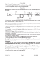
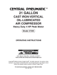
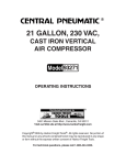
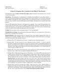
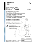
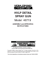
®
HVLP DETAIL
SPRAY GUN
Model 46719
ASSEMBLY and OPERATING
INSTRUCTIONS
®
3491 Mission Oaks Blvd., Camarillo, CA 93011
Visit our Web site at http://www.harborfreight.com
Copyright © 2002 by Harbor Freight Tools®. All rights reserved. No portion of this
manual or any artwork contained herein may be reproduced in any shape or form
without the express written consent of Harbor Freight Tools.
For technical questions and replacement parts, please call 1-800-444-3353
Specifications
Cup Capacity
Air Inlet
Recommended PSI
Dimensions
Nozzle Size
Weight
Recommended Hose
5.3 Ounces
1/4” NPS
43 PSI
12-3/4” x 6-1/8” x 3-7/8”
0.039”
1.15 Lbs.
3/8” I.D.
Save This Manual
You will need the manual for the safety warnings and precautions, assembly instructions,
operating and maintenance procedures, parts list and diagram. Keep your invoice with this
manual. Write the invoice number on the inside of the front cover. Keep the manual and
invoice in a safe and dry place for future reference.
Safety Warnings and Precautions
WARNING: When using tool, basic safety precautions should always be followed to
reduce the risk of personal injury and damage to equipment.
Read all instructions before using this tool!
1.
Keep work area clean. Cluttered areas invite injuries.
2.
Observe work area conditions. Do not use machines or power tools in damp or wet
locations. Don’t expose to rain. Keep work area well lighted. Do not use electrically
powered tools in the presence of flammable gases or liquids.
3.
Keep children away. Children must never be allowed in the work area. Do not let
them handle machines, tools, or extension cords.
4.
Store idle equipment. When not in use, tools must be stored in a dry location to
inhibit rust. Always lock up tools and keep out of reach of children.
5.
Do not force tool. It will do the job better and more safely at the rate for which it was
intended. Do not use inappropriate attachments in an attempt to exceed the tool
capacity.
6.
Use the right tool for the job. Do not attempt to force a small tool or attachment to
do the work of a larger industrial tool. There are certain applications for which this tool
was designed. Do not modify this tool and do not use this tool for a purpose for which
it was not intended.
7.
Dress properly. Do not wear loose clothing or jewelry as they can be caught in
moving parts. Protective, electrically non-conductive clothes and non-skid footwear
are recommended when working. Wear restrictive hair covering to contain long hair.
8.
Use eye and ear protection. Always wear ANSI approved impact safety goggles.
Wear an ANSI approved dust respirator when spraying.
SKU 46719
Page 2
REV 01/02
9.
Do not overreach. Keep proper footing and balance at all times. Do not reach over
or across running machines.
10. Maintain tools with care. Keep tools clean for better and safer performance. Follow
instructions for lubricating and changing accessories. Inspect tool cords and hoses
periodically and, if damaged, have them repaired by an authorized technician. The
handles must be kept clean, dry, and free from oil and grease at all times.
11. Disconnect power. When not in use disconnect from compressor.
12. Remove adjusting keys and wrenches. Check that keys and adjusting wrenches
are removed from the tool or machine work surface before plugging it in.
13. Avoid unintentional starting. Do not carry any tool with your finger on the trigger,
whether it is plugged in or not.
14. Stay alert. Watch what you are doing, use common sense. Do not operate any tool
when you are tired.
15. Check for damaged parts. Before using any tool, any part that appears damaged
should be carefully checked to determine that it will operate properly and perform its
intended function. Check for alignment and binding of moving parts; any broken parts
or mounting fixtures; and any other condition that may affect proper operation. Any
part that is damaged should be properly repaired or replaced by a qualified
technician. Do not use the tool if any switch does not turn On and Off properly.
16. Guard against electric shock. Prevent body contact with grounded surfaces such as
pipes, radiators, ranges, and refrigerator enclosures.
17. Replacement parts and accessories. When servicing, use only identical
replacement parts. Use of any other parts will void the warranty.
18. Do not operate tool if under the influence of alcohol or drugs. Read warning
labels on prescriptions to determine if your judgment or reflexes are impaired while
taking drugs. If there is any doubt, do not operate the tool.
19. Use proper size and type extension cord. If an extension cord is required, it must
be of the proper size and type to supply the correct current to the air compressor
without heating up. Otherwise, the extension cord could melt and catch fire, or cause
electrical damage to the air compressor. Check air compressor manual.
20. Maintenance. For your safety, maintenance should be performed regularly by a
qualified technician.
21. Keep aware of air hoses. Be careful not to trip over air hoses while working. Check
air connections periodically.
22. Do not operate Spray Gun near open flames, pilot lights, heaters, or any other
heat source. Make sure you have adequate ventilation. Most solvents and paints
are extremely flammable, especially when sprayed. Never smoke cigarettes in the
same room you are working in.
SKU 46719
Page 3
23. Read labels on cleaning solvents and paint coatings. Chlorinated solvents such
as 111-Trichloroethane and Methylene Chloride (also known as methyl-chloride) can
chemically react with aluminum and may explode. Many paint sprayers contain
aluminum. Contact solvent manufacturer or paint supplier if your are in doubt.
24. Paints and solvents may be harmful or fatal if swallowed or inhaled. Always use
a respirator when spraying. Avoid prolonged skin contact with solvents or paints as
they will irritate skin. After contact, immediately wash off exposed area with hot,
soapy water.
25. Check all Spray Gun Seals and Air Connection. Before use, make sure the
Lid (#14) is fully tightened to the Cup (#13). Make sure the air hose is securely
fastened to the Body (#3).
Note: Performance of the compressor (if powered by line voltage) may vary depending
on variations in local line voltage. Extension cord usage may also affect tool performance.
Warning: The warnings, cautions, and instructions discussed in this instruction manual
cannot cover all possible conditions and situations that may occur. It must be understood by the operator that common sense and caution are factors which cannot be
built into this product, but must be supplied by the operator.
WARNING: This product contains or, when used, produces a chemical known to the
State of California to cause cancer and birth defects or other reproductive harm.
(California Health & Safety Code 25249.5, et seq.)
Unpacking
When unpacking, check to make sure the parts listed on page 8 are included. If any parts
are missing or broken, please call Harbor Freight Tools at the number on the cover of this
manual as soon as possible.
SKU 46719
Page 4
Assembly
Refer to Assembly Drawing on page 9.
1. To attach the Cup (#13), screw it onto the Material Sleeve (#10).
2. Screw the Regulator (#30) onto the Air Connector (#28).
Operation
Warning! Never allow the Spray Gun and Cup (#13) to lay on it’s side when the Cup (#13) is
full of paint.
Spray
Gun
For best service, you should incorporate an oiler, a regulator, and an inline air filter, as shown
above. All are available at Harbor Freight Tools.
Note: It is recommended that you test the Spray Gun on scrap material, to become familiar
with the available adjustments, prior to use.
1. Remove the Lid (#14) on the Cup (#13) and add no more than 5.3 ounces of paint. Replace
the Lid (#14).
2. Connect the air hose to the Regulator (#30) and set the pressure to 43 PSI. Do not
exceed 43 PSI.
3. Squeeze the Trigger (#15) to test the pattern.
4. Spray from a distance of approximately four to eight inches while keeping the Spray Gun
perpendicular to the ground.
5. Maintain your distance as you evenly move from side to side. Do not fan or arc the Spray
Gun or the paint will apply unevenly.
6. When you finish spraying, release the Trigger (#15), and disconnect the air hose.
7. Empty the Cup (#13). Never store the Cup (#13) with paint in it.
Warning! Even after the compressor is shut down, the Cup (#13) may still be pressurized.
Open it slowly and carefully.
Adjustments
1. You can fine tune the air pressure by slowly turning the Regulator (#30) and the Air
Adjustment Screw Valve Assy. (#29). You may also adjust the pressure with the air compressor. Make sure you do not exceed the recommended 43 PSI.
2. You can adjust the amount of fluid coming through the gun with the Fluid Control
Knob (#19). Loosen the Fluid Contol Knob Lock (#20), make the adjustment, and tighten
the Fluid Contol Knob Lock (#20).
Warning! Keep your hand away from the Trigger (#15) while adjusting jet shape..
3. To adjust the spray pattern, turn the Air Cap (#1).
SKU 46719
Page 5
REV 05/03
TroubleShooting
Problem 1: Heavy top/bottom, or right/left pattern.
Cause:
Material buildup on Air Cap (#1).
Partially plugged Air Cap (#1) center holes.
Solution:
Remove Air Cap (#1), soak in solvent, and wipe clean.
Cause:
Material partially plugging Tip of Gun.
Solution:
Remove Tip and clean.
Cause:
Damaged Paint Needle (#22).
Solution:
Have a qualified technician replace the Paint Needle (#22) .
Problem 2: Heavy Center Pattern
Cause:
Too much paint.
Solution:
Reduce fluid flow with the Fluid Control Knob (#19).
Loosen the the Fluid Contol Knob Lock (#20), make the adjustment and
tighten the Fluid Contol Knob Lock (#20).
Cause:
Coating too thick.
Solution:
Thin out coating.
Problem 3: Split spray pattern.
Cause:
Pressure too high.
Solution:
Reduce air pressure at the regulator.
Cause:
Not enough paint.
Solution:
Increase fluid flow with the Fluid Control Knob (#19).
Loosen the the Fluid Contol Knob Lock (#20), make the adjustment, and
tighten the Fluid Contol Knob Lock (#20)..
Problem 4: Jerky or fluttering spray.
Cause:
Insufficient paint.
Solution:
Fill Cup (#13).
Cause:
Gun and Cup (#13) tipped at excessive angle.
Solution:
Correct angle.
Problem 5: Air mixes with paint.
Cause:
Worn O-ring (#2).
Solution:
Have a qualified technician replace the O-ring (#2).
SKU 46719
Page 6
Maintenance
Cleaning (Gun should be attached to compressor to complete the cleaning process)
Warning!! Do not use paint strippers on this unit as they will damage the aluminum. Never
allow the unit to lay on it’s side while paint is in the Cup (#13).
1. Empty paint from Cup (#13) and add small amount of clean solvent. Replace Lid (#14)
and shake Cup (#13) vigorously. At the lowest possible pressure, spray out the solvent into a
waste bucket (make sure you are wearing respirator and eye protection).
2. Empty Cup (#13) of remaining solvent and repeat the process until the Cup (#13) solvent
appears clean and free of the paint.
3. Disconnect air supply. Remove surplus solvent and wipe the Cup (#13) clean with a lint
free cloth.
Note: The Cup (#13) may be fully immersed in solvent for no more than 24 hours if needed.
4. Remove the Air Cap (#1) and the Fluid Nozzle (#4). Remove the Gasket (#5) and
unscrew the Packing Screw (#6), and remove it. Use the Brush (#12) to clean the Paint
Needle (#22) with solvent. When replacing the Packing Screw (#6), do not over-tighten.
Over-tightening of the Packing Screw (#6) will result in leakage. Unscrew the Fluid Control
Knob Lock (#20) and remove the Fluid Control Knob (#19). Use the Brush (#12) to clean
the gun body opening that the Fluid Control Knob (#19) fits in, and clean all of the parts.
Reassemble gently. Do not force any parts or they will break.
Note: Always dispose of paints and solvents properly. Consult the local hazardous
waste authority for proper disposal procedures and sites.
SKU 46719
Page 7
Parts List
Part No. Description
1*
Air Nozzle with Brass Cap
2*
0-ring
3
Body
4*
Fluid Nozzle
5*
Gasket
6
Packing Screw
7*
Tallon Seal
8*
Spring
9
Connector
10* Material Sleeve
11
Wrench
12
Brush
13
Cup
14
Lid
15
Trigger
16
0-ring
17
Screw
18
Trigger Pin
19
Fluid Control Knob
20
Fluid Control Knob Lock
21
Paint Needle Spring
22* Paint Needle
23* Washer
24
Air Valve Assembly
25
Screw
26
Control Knob
27
Spray Regulating Nut Assy.
28
Air Connector ( 1/4 NPS)
29
Air Adjusting Valve Assembly
30
Regulator
31
Gasket
32
Gasket
33
Gasket
*Not available individually as replacement parts
(see Repair Kit and Nozzle Set below)
97080S-RK Repair Kit (Includes #5,7,8,2,23,10)
97080S-NA 1.0MM Nozzle Set (Includes #1,4,22)
NOTE: Some parts are listed and shown for illustration purposes only and are not available
individually as replacement parts.
SKU 46719
Page 8
REV 01/02; REV 07/06
Assembly Drawing
Part Notes: 1. Part # 24 is a set including 24a, 24b, 24c, 24d, 24e. Parts 24a through 24e
are not listed on the parts list on page 8.
2. Part # 27 is a set including 27a, 27b, 27c, 27d. Parts 27a through 27d are not
listed on the parts list on page 8.
3. Part # 29 is a set including 29a, 29b, 29c, 29d. Parts 29a through 29d are not
listed on the parts list on page 8.
PLEASE READ THE FOLLOWING CAREFULLY
THE MANUFACTURER AND/OR DISTRIBUTOR HAS PROVIDED THE PARTS DIAGRAM IN THIS
MANUAL AS A REFERENCE TOOL ONLY. NEITHER THE MANUFACTURER NOR DISTRIBUTOR MAKES ANY REPRESENTATION OR WARRANTY OF ANY KIND TO THE BUYER THAT HE
OR SHE IS QUALIFIED TO MAKE ANY REPAIRS TO THE PRODUCT OR THAT HE OR SHE IS
QUALIFIED TO REPLACE ANY PARTS OF THE PRODUCT. IN FACT, THE MANUFACTURER
AND/OR DISTRIBUTOR EXPRESSLY STATES THAT ALL REPAIRS AND PARTS REPLACEMENTS
SHOULD BE UNDERTAKEN BY CERTIFIED AND LICENSED TECHNICIANS AND NOT BY THE
BUYER. THE BUYER ASSUMES ALL RISK AND LIABILITY ARISING OUT OF HIS OR HER
REPAIRS TO THE ORIGINAL PRODUCT OR REPLACEMENT PARTS THERETO, OR ARISING
OUT OF HIS OR HER INSTALLATION OF REPLACEMENT PARTS THERETO.
SKU 46719
SKU 46719
Page 9
Page 9
REV 07/06