1
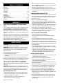
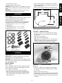
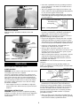
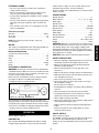
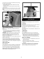
SANDER
Model No.
ASSEMBLY
Oscillating
Spindle
SAFETY
Operator’s Manual
351.215000
OPERATION
MAINTENANCE
Sears, Roebuck and Co., Hoffman Estates, IL 60179 U.S.A.
www.sears.com/craftsman
25759.00 Draft (01/22/08)
ESPAÑOL
all Safety Rules and Operating
Instructions before First Use
of this Product. Keep this
manual with tool.
PARTS LIST
CAUTION: Read and follow
• Wear safety glasses complying with United States ANSI
Z87.1. Everyday glasses have only impact resistant lenses.
They are NOT safety glasses.
• Wear face mask or dust mask if operation is dusty.
• Be alert and think clearly. Never operate power tools when
tired, intoxicated or when taking medications that cause
drowsiness.
TABLE OF CONTENTS
Warranty. . . . . . . . . . . . . . . . . . . . . . . . . . . . . . . . . . . . . . . . . 2
Safety Rules . . . . . . . . . . . . . . . . . . . . . . . . . . . . . . . . . . . . 2-3
Unpacking . . . . . . . . . . . . . . . . . . . . . . . . . . . . . . . . . . . . . . . 3
Assembly . . . . . . . . . . . . . . . . . . . . . . . . . . . . . . . . . . . . . . 3-4
Installation. . . . . . . . . . . . . . . . . . . . . . . . . . . . . . . . . . . . . . 4-5
Operation . . . . . . . . . . . . . . . . . . . . . . . . . . . . . . . . . . . . . . 5-6
Maintenance . . . . . . . . . . . . . . . . . . . . . . . . . . . . . . . . . . . . . 6
Troubleshooting . . . . . . . . . . . . . . . . . . . . . . . . . . . . . . . . . . . 7
Parts Illustration and List . . . . . . . . . . . . . . . . . . . . . . . . . . 8-9
Español. . . . . . . . . . . . . . . . . . . . . . . . . . . . . . . . . . . . . . 12-19
PREPARE WORK AREA FOR JOB
• Keep work area clean. Cluttered work areas invite accidents.
• Do not use power tools in dangerous environments. Do not
use power tools in damp or wet locations. Do not expose
power tools to rain.
• Work area should be properly lighted.
• Proper electrical receptacle should be available for tool.
Three-prong plug should be plugged directly into properly
grounded, three-prong receptacle.
• Extension cords should have a grounding prong and the three
wires of the extension cord should be of the correct gauge.
• Keep visitors at a safe distance from work area.
• Keep children out of workplace. Make workshop childproof.
Use padlocks, master switches or remove switch keys to
prevent any unintentional use of power tools.
WARRANTY
ONE-YEAR FULL WARRANTY ON CRAFTSMAN
TOOL
If this Craftsman tool fails due to a defect in material or workmanship within one year from the date of purchase, call 1800-4-MY-HOME® TO ARRANGE FOR FREE REPAIR (or
replacement if repair proves impossible). This warranty does
not include expendable parts, such as lamps, batteries, bits or
blades.
If this tool is ever used for commercial or rental purposes, this
warranty will apply for only 90 days from the date of purchase.
This warranty gives you specific legal rights and you may also
have other rights which vary from state to state.
Sears, Roebuck and Co., Hoffman Estates, IL 60179
TOOL SHOULD BE MAINTAINED
• Always unplug tool prior to inspection.
• Consult manual for specific maintaining and adjusting
procedures.
• Keep tool lubricated and clean for safest operation.
• Remove adjusting tools. Form habit of checking to see that
adjusting tools are removed before switching machine on.
• Keep all parts in working order. Check to determine that the
guard or other parts will operate properly and perform their
intended function.
• Check for damaged parts. Check for alignment of moving
parts, binding, breakage, mounting and any other condition
that may affect a tool’s operation.
• A guard or other part that is damaged should be properly
repaired or replaced. Do not perform makeshift repairs.
(Use parts list provided to order replacement parts.)
SAFETY RULES
WARNING: For your own safety, read all of the instructions
and precautions before operating tool.
WARNING: Some dust created by power sanding, sawing,
grinding, drilling and other construction activities contains
chemicals known to cause cancer, birth defects or other
reproductive harm.
Some examples of these chemicals are:
• Lead from lead-based paints.
• Crystalline silica from bricks and cement and other masonry products.
• Arsenic and chromium from chemically-treated lumber.
Your risk from these exposures vary, depending on how often
you do this type of work. To reduce your exposure to these
chemicals: work in a well ventilated area and work with
approved safety equipment. Always wear OSHA/NIOSH
approved, properly fitting face mask or respirator when using
such tools.
KNOW HOW TO USE TOOL
• Use right tool for job. Do not force tool or attachment to do
a job for which it was not designed.
• Disconnect tool when changing sanding drum.
• Avoid accidental start-up. Make sure that the tool is in the
“OFF” position before plugging in.
• Do not force tool. It will work most efficiently at the rate for
which it was designed.
• Keep hands away from moving parts and sanding surfaces.
• Never leave tool running unattended. Turn the power off
and do not leave tool until it comes to a complete stop.
• Do not overreach. Keep proper footing and balance.
• Never stand on tool. Serious injury could occur if tool is
tipped or if belt or disc are unintentionally contacted.
• Know your tool. Learn the tool’s operation, application and
specific limitations.
• Use recommended accessories (refer to page 9). Use of
improper accessories may cause risk of injury to persons.
• Handle the workpiece correctly. Protect hands from
possible injury.
CAUTION: Always follow proper operating procedures as
defined in this manual even if you are familiar with use of this
or similar tools. Remember that being careless for even a
fraction of a second can result in severe personal injury.
BE PREPARED FOR JOB
• Wear proper apparel. Do not wear loose clothing, gloves,
neckties, rings, bracelets or other jewelry which may get
caught in moving parts of machine.
• Wear protective hair covering to contain long hair.
• Wear safety shoes with non-slip soles.
© Sears, Roebuck and Co.
2
22½″
WARNING: Do not attempt to operate tool until it is completely assembled according to the instructions.
SAFETY
• Sander can be installed on a workbench or a tool stand
(see Recommended Accessories, page 9) using bolts, lock
washers and hex nuts.
• Figure 2 shows the base dimensions and mounting holes.
• Turn machine off if it jams.
• Support workpiece with work table.
CAUTION: Think safety! Safety is a combination of operator
common sense and alertness at all times when tool is being
used.
13¾″
UNPACKING
D
11″
5/16″
16½″
Diameter
Figure 2 - Base Dimension and Mounting Holes
ATTACH ABRASIVE SLEEVES
Refer to Figures 3 and 4, pages 3 and 4.
E
TO ATTACH ½″ ABRASIVE SLEEVE:
• Place the ½″ table insert over spindle and onto the table.
The top side of the insert has directional arrows stamped
into the insert.
• Slide sleeve over the spindle.
• Secure sleeve in position with knob.
NOTE: Knob has left hand thread – turn counterclockwise
to tighten, clockwise to loosen. Knob must seat on sleeve
securely so that sleeve will not spin loose on spindle.
A
Knob
B
Sleeve
C
Figure 1 - Unpacking Sander
ASSEMBLY
Refer to Figures 2 - 5.
CAUTION: Do not attempt assembly if parts are missing.
Use this manual to order replacement parts.
WARNING: Do not operate machine until completely assem-
Direction Arrow
on Insert
bled. Do not operate machine until you have completely read
and understood this manual.
Figure 3 - Attaching the ½″ Sleeve
MOUNT SANDER
TO ATTACH ¾″ – 3″ ABRASIVE SLEEVES:
Example: 2″
• Place the 2″ table insert over spindle and onto the table.
The top side of the insert has directional arrows stamped
into the insert.
• Slide 2″ sleeve over the 2″ drum.
• Slide drum with sleeve onto spindle. Place 2″ drum washer
on drum and secure drum in position with knob. Knob and
washer must hold drum firmly so that it does not spin loose
on spindle.
Refer to Figure 2.
Choose a suitable location to mount the sander. The sander
must be installed in a place with ample lighting and correct
power supply. To install sander:
• The sander must be bolted to a firm, level surface.
• Make sure there is plenty of room for moving the workpiece. There must be enough room that neither operators
nor bystanders will have to stand in line with the wood
while using the tool.
3
ASSEMBLY
Refer to Figure 1.
Check for shipping damage. If damage has occurred, a claim
must be filled with carrier. Check for completeness.
Immediately report missing parts to dealer.
The sander comes assembled as one unit. Additional parts
should be located and accounted for before assembling.
A Table Inserts (6), (½″, ¾″, 1″, 1½″, 2″ and 3″)
B Spindle Knob
C Drum Washers (5), (¾″, 1″, 1½″, 2″ and 3″)
D Spindle Drums (5), (¾″, 1″, 1½″, 2″ and 3″)
E Abrasive Sleeves (6), (½″, ¾″, 1″, 1½″, 2″ and 3″)
• Check with a qualified electrician if grounding instructions
are not understood or if in doubt as to whether the tool is
properly grounded.
• This tool is equipped with an approved 3-conductor cord
rated at 150V and a 3-prong grounding type plug (Figure 6)
for your protection against shock hazards.
• Grounding plug should be plugged directly into a properly
installed and grounded 3-prong grounding-type receptacle,
as shown (Figure 6).
Knob
2″ Drum
Washer
Properly Grounded Outlet
Grounding Prong
3-Prong Plug
Direction Arrow
on Insert
Figure 4 - Attaching 2″ Drum with Sleeve
Figure 6 - 3-Prong Receptacle
ONBOARD STORAGE
• Do not remove or alter grounding prong in any manner. In
the event of a malfunction or breakdown, grounding provides a path of least resistance for electrical shock.
Onboard storage is provided for all drums, inserts and
washers.
WARNING: Do not permit fingers to touch the terminals of
plug when installing or removing from outlet.
• Plug must be plugged into matching outlet that is properly
installed and grounded in accordance with all local codes
and ordinances. Do not modify plug provided. If it will not fit
in outlet, have proper outlet installed by a qualified electrician.
• Inspect tool cords periodically, and if damaged, have
repaired by an authorized service facility.
• Green (or green and yellow) conductor in cord is the
grounding wire. If repair or replacement of the electric cord
or plug is necessary, do not connect the green (or green
and yellow) wire to a live terminal.
• Where a 2-prong wall receptacle is encountered, it must be
replaced with a properly grounded 3-prong receptacle
installed in accordance with National Electric Code and
local codes and ordinances.
Table
Inserts
Drum Washers
Drums
with
Sleeves
Figure 5 – Onboard Storage
WARNING: This work should be performed by a qualified
electrician.
A temporary 3-prong to 2-prong grounding adapter (see
Figure 7) is available for connecting plugs to a two pole outlet
if it is properly grounded.
INSTALLATION
Refer to Figures 6, 7 and 8, pages 4 and 5.
POWER SOURCE
WARNING: Do not connect sander to the power source until
Grounding Lug
Adapter
all assembly steps have been completed.
The motor is designed for operation on the voltage and frequency specified. Normal loads will be handled safely on voltages not more than 10% above or below specified voltage.
Running the unit on voltages which are not within range may
cause overheating and motor burn-out. Heavy loads require
that voltage at motor terminals be no less than the voltage
specified on nameplate.
• Power supply to the motor is controlled by a single pole
locking rocker switch. Remove the key to prevent unauthorized use.
3-Prong Plug
Make Sure This
Is Connected
To A Known
Ground
2-Prong
Receptacle
Figure 7 - 2-Prong Receptacle with Adapter
• Do not use a 3-prong to 2-prong grounding adapter unless
permitted by local and national codes and ordinances.
(A 3-prong to 2-prong grounding adapter is not permitted in
Canada.) Where permitted, the rigid green tab or terminal on
the side of the adapter must be securely connected to a
permanent electrical ground such as a properly grounded
water pipe, a properly grounded outlet box or a properly
grounded wire system.
• Many cover plate screws, water pipes and outlet boxes are
not properly grounded. To ensure proper ground, grounding
means must be tested by a qualified electrician.
GROUNDING INSTRUCTIONS
WARNING: Improper connection of equipment grounding
conductor can result in the risk of electrical shock. Equipment
should be grounded while in use to protect operator from
electrical shock.
4
EXTENSION CORDS
Sander features a large 18″ cast iron table, dust port and
onboard storage of durms, inserts and washers.
Six sizes of drums are included. Dust port is sized to fit Sears
wet/dry vacuums.
• The use of any extension cord will cause some drop in
voltage and loss of power.
• Wires of the extension cord must be of sufficient size to
carry the current and maintain adequate voltage.
• Use the table to determine the minimum wire size (A.W.G.)
extension cord.
• Use only 3-wire extension cords having 3-prong grounding
type plugs and 3-pole receptacles which accept the tool
plug.
• If the extension cord is worn, cut, or damaged in any way,
replace it immediately.
SPECIFICATIONS
Extension Cord Length
Wire Size . . . . . . . . . . . . . . . . . . . . . . . . . . . . . . . . . . . A.W.G.
Up to 25 ft. . . . . . . . . . . . . . . . . . . . . . . . . . . . . . . . . . . . . . . 18
25 to 50 ft. . . . . . . . . . . . . . . . . . . . . . . . . . . . . . . . . . . . . . . 16
NOTE: Using extension cords over 50 ft. long is not
recommended.
MOTOR
The sander is assembled with motor and wiring installed. The
electrical wiring schematic is shown in Figure 8.
MOTOR SPECIFICATIONS:
Horsepower (Continuous Duty). . . . . . . . . . . . . . . . . . . . . . . 1/4
Voltage . . . . . . . . . . . . . . . . . . . . . . . . . . . . . . . . . . . . . . . . 120
Amp. . . . . . . . . . . . . . . . . . . . . . . . . . . . . . . . . . . . . . . . . . . 2.6
Hertz . . . . . . . . . . . . . . . . . . . . . . . . . . . . . . . . . . . . . . . . . . 60
Phase. . . . . . . . . . . . . . . . . . . . . . . . . . . . . . . . . . . . . . . Single
RPM . . . . . . . . . . . . . . . . . . . . . . . . . . . . . . . . . . . . . . . . . 1725
CAUTION: Always observe following safety precautions.
SAFETY PRECAUTIONS
• Whenever adjusting or replacing any parts on the tool, turn
switch OFF and remove the plug from power source.
• Make sure all guards are properly attached. All guards
should be securely fastened.
• Make sure all moving parts are free and clear of any
interference.
• Make sure all fasteners are tight and have not vibrated loose.
• With power disconnected, test operation by hand for clearance and adjust if necessary.
• Always wear eye protection or face shield.
• After turning switch on, always allow drum to come up to
full speed before sanding.
• Be sure drum turns clockwise.
• Avoid kickback by sanding in accordance with the directional arrows.
• Keep your hands clear of abrasive sleeve and drum.
• For optimum performance, do not stall motor or reduce
speed. Do not force the work into the abrasive.
• Always support workpiece with table.
• Never push a sharp corner of the workpiece rapidly against
sleeve. Abrasive backing may tear.
• Replace abrasives when they become loaded (glazed) or
frayed.
• Never use machine for wet sanding which can create
hazard of electrical shock.
ELECTRICAL CONNECTIONS
WARNING: All electrical connections must be performed by
a qualified electrician. Make sure tool is off and disconnected
from power source while motor is mounted, connected, reconnected or anytime wiring is inspected.
Motor and wires are installed as shown in wiring schematic
(See Figure 8). Motor is assembled with approved,
3-conductor cord to be used at 120 volts.
Switch
Line Cord
Motor
Figure 8 - Wiring Schematic
The power lines are inserted directly onto the switch. The
green ground line must remain securely fastened to the frame
to properly protect against electrical shock. The power supply
to the motor is controlled by a single pole locking rocker switch.
• Remove the key to prevent unauthorized use.
OPERATION
ON/OFF SWITCH
Refer to Figure 9, page 6.
The ON/OFF switch is located on the upper front right of the
base. To turn the sander ON, pull the switch to the up
position. To turn the sander OFF, push the switch to the down
position.
Refer to Figures 9 and 10.
DESCRIPTION
The Craftsman Oscillating Spindle Sander makes sanding
irregular shapes and curves in wood easy and convenient.
5
OPERATION
Spindle diameter . . . . . . . . . . . . . . . . . . . . . . . . . . . . . . . . . ½″
Drum diameters. . . . . . . . . . . . . . . . . . . ¾″, 1″, 1½″, 2″ and 3″
Drum length. . . . . . . . . . . . . . . . . . . . . . . . . . . . . . . . . . . . 4½″
Spindle stroke. . . . . . . . . . . . . . . . . . . . . . . . . . . . . . . . . . . . 1″
Spindle oscillation . . . . . . . . . . . . . . . . . . . . . . . . . . . . 30 SPM
Spindle speed . . . . . . . . . . . . . . . . . . . . . . . . . . . . . 1725 RPM
Table diameter . . . . . . . . . . . . . . . . . . . . . . . . . . . . . . . . . . 18″
Table height . . . . . . . . . . . . . . . . . . . . . . . . . . . . . . . . . . . 14½″
Dust port diameter. . . . . . . . . . . . . . . . . . . . . . . . . . . . . 2.086″
Base dimensions . . . . . . . . . . . . . . . . . . . . . . . . . 22½ x 16½″
Switch . . . . . . . . . . . . . . . . . . . . . . . . . . . . . SP, Locking rocker
Weight . . . . . . . . . . . . . . . . . . . . . . . . . . . . . . . . . . . . . . 52 lbs
WARNING: Operation of any power tool can result in foreign
objects being thrown into the eyes, which can result in severe
eye damage. Always wear safety goggles complying with
United States ANSI Z87.1 (shown on package) before commencing power tool operation. Safety goggles are available at
Sears retail stores or catalog.
The sander can be locked from unauthorized use by locking
the switch. To lock the switch:
• Turn the switch to OFF position and disconnect sander
from power source.
• Pull the key out. The switch cannot be turned on with the
key removed.
NOTE: Should the key be removed from the switch at the ON
position, the switch can be turned off but cannot be turned on
again.
• To replace key, slide key into the slot on switch until it snaps.
Dust Port
Figure 10 – Location of Dust Port
MAINTENANCE
WARNING: Make certain that the unit is disconnected from
power source before attempting to service or remove any
component.
CLEANING
Keep machine and workshop clean. Do not allow sawdust to
accumulate on the tool. Keep the drums clean.
Be certain motor is kept clean and is frequently vacuumed
free of dust.
Use soap and water to clean painted parts, rubber parts and
plastic guards.
Figure 9 – Locking Switch in OFF Position
BASIC SANDING OPERATION
NOTE: This tool is approved for sanding wood and wood
products only.
• Select and install the desired sanding sleeve and drum for
the particular application. Choose the size that is similar to
the contour of your workpiece.
LUBRICATION
Refer to Figure 11.
The shielded ball bearings in this tool are permanently
lubricated at the factory. They require no further lubrication.
• Apply a light coat of paste wax to the work table. This will
make it easier to feed the work and also prevent rust.
• Periodically apply grease to the worm gear (Ref. No. 54).
WARNING: Failure to use the correct size table insert with
its matching sanding sleeve could result in fingers being
pinched or the workpiece being pulled down between the
table insert and sanding sleeve.
In general, coarse grit removes the most material and fine grit
produces a better finish.
For best results, start with a coarse grit and sand until the
surface is uniform. Medium grit may then be used to remove
scratches left by the coarser grit and finer grit used for finishing of the surface. Always continue sanding with each grit until
surface is uniform.
KEEP TOOL IN REPAIR
• If power cord is worn, cut, or damaged in any way, have it
replaced immediately.
• Replace worn abrasives when needed.
• Replace any damaged or missing parts. Use parts list to
order parts.
Any attempt to repair motor may create a hazard unless
repair is done by a qualified service technician. Repair
service is available at your nearest Sears store.
DUST COLLECTION
Refer to Figure 10.
A dust collection port has been provided; it is located beneath
the work table on the rear side of the sander. The dust port is
sized to fit the vacuum hose of Craftsman wet/dry vacuums.
The use of dust collection is highly recommended. Sawdust
buildup beneath the table may prevent the spindle from oscillating completely, causing damage to the tool.
6
TROUBLESHOOTING
SYMPTOM
POSSIBLE CAUSE(S)
CORRECTIVE ACTION
Motor will not start
1. Low voltage
2. Open circuit in motor or loose
connections
3. Defective switch
4. Defective capacitor
1. Check power line for proper voltage
2. Inspect all lead connections on motor for loose or
open connection
3. Replace switch
4. Replace capacitor
Motor will not start;
fuses blown or circuit
breakers are tripped
1. Short circuit in line cord or plug
1. Inspect line cord or plug for damaged insulation and
shorted wires
2. Inspect all lead connections on motor for loose or
shorted terminals or worn insulation on wires
3. Install correct fuses or circuit breakers
2. Short circuit in motor or loose
connections
3. Incorrect fuses or circuit breakers in
power line
Motor fails to develop full 1. Power line overloaded with lights,
appliances and other motors
power (power output of
motor decreases rapidly
2. Undersize wires or circuits too long
with decrease in voltage at 3. General overloading of power
motor terminals)
company's facilities
1. Reduce the load on the power line
2. Increase wire sizes, or reduce length of wiring
3. Request a voltage check from the power company
Motor overheats
Motor overloaded
Reduce load on motor
Motor stalls (resulting in
blown fuses or tripped
circuit breakers)
1. Short circuit in motor or loose
connections
2. Low voltage
3. Incorrect fuses or circuit breakers in
power line
4. Motor overload
1. Inspect connections in motor for loose or shorted
terminals or worn insulation on lead wires
2. Correct the low line voltage conditions
3. Install correct fuses or circuit breakers
Machine slows down
while operating or
sandpaper slips on drum
1. Applying too much pressure to
workpiece
2. Spindle knob loose
1. Ease up on pressure
Wood burns while
sanding; sandpaper not
removing wood
Sandpaper glazed or loaded with
sawdust
Replace sandpaper
Spindle does NOT travel
completely through 1″
stroke
1. Sawdust build-up below table insert
2. Damaged or loose oscillating
mechanism
1. Remove sawdust with vacuum
2. Inspect mechanism. Contact Sears Service Center
if necessary
Excessive noise
Note: Normally operating
sander does make some
noise
Spindle and motor not aligned properly
Adjust motor and spindle alignment
4. Reduce load on motor
7
MAINTENANCE
2. Tighten spindle knob
Model 351.215000
Figure 11 - Replacement Parts Illustration for Sander
1
2
3
37
37
22
4
33
37
39
5
36
40
41
6
42
43
44
66
7
45
8
46
55
9
47
47
10
49
48
45
11
46
50
12
14
51
54
9
57
16
15
52
13
53
60
20
61
59
21
62
22
17
18
23
58
27
24
28
19
11
26
27
65
51
12
30
31
29
63
25
38
32
64
33
56
34
35
36
8
22
REPLACEMENT PARTS LIST FOR SANDER
KEY
NO.
PART NO.
DESCRIPTION
1
2
26019.00
26020.00
3
26021.00
4
26022.00
5
26023.00
Knob
Drum Washer
(set of 5: ¾″, 1″, 1½″, 2″, 3″)
Abrasive Sleeve
(set of 6: ½″, ¾″, 1″, 1½″, 2″, 3″)
Rubber Drum
(set of 5: ¾″, 1″, 1½″, 2″, 3″)
Table Inserts
(set of 6: ½″, ¾″, 1″, 1½″, 2″, 3″)
Table
Fan
Gasket
5-0.8 x 10mm Flat Head Screw
Fan Housing
5mm Flat Washer*
5-0.8 x 12mm Socket Head Bolt*
Seal
6003ZZ Ball Bearing*
Bearing Retainer
Spindle
5-0.8mm Fiber Hex Nut*
Bushing (set of 2)
5-0.8 x 40mm Socket Head Bolt*
3AMI-17 Retaining Ring
Collar
8mm Wavy Washer
61903ZZ Ball Bearing
3AMI-30 Retaining Ring
Bracket Assembly
Rod End
5mm Lock Washer*
5-0.8mm Hex Nut*
Foot
8-1.25mm Hex Nut*
8mm Lock Washer*
Shoulder Screw
8mm Flat Washer*
6
7
8
9
10
11
12
13
14
15
16
17
18
19
20
21
22
23
24
25
26
27
28
29
30
31
32
33
1
1
1
1
1
1
1
1
3
1
6
6
1
1
1
1
1
1
1
1
1
3
1
1
1
1
1
1
4
2
1
1
2
PART NO.
DESCRIPTION
34
35
36
37
38
39
40
41
42
43
44
45
46
47
48
49
50
51
52
53
54
55
56
26037.00
26038.00
STD843610
26039.00
26054.00
26041.00
26042.00
26043.00
01043.00
26044.00
STD851010
STD852010
STD841015
01516.00
26045.00
26046.00
00533.00
STD851006
STD852006
STD870616
26047.00
26048.00
22897.00
57
58
59
60
01474.00
20747.00
26049.00
26050.00
61
26051.00
Link
Bushing
6-1.0mm Fiber Hex Nut*
Motor Stud (set of 3)
Base Cover
Screw
Bushing
Pivot
6-1.0 x 8mm Set Screw
Motor
10mm Flat Washer*
10mm Lock Washer*
10-1.5mm Hex Nut*
5-0.8 x 8mm Set Screw
Block
Cam
3AMI-15 Retaining Ring
6mm Flat Washer*
6mm Lock Washer*
6-1.0 x 16mm Socket Head Bolt*
Worm Gear
Worm
4.2-1.6 x 9.5mm Thread Forming
Round Head Screw
5mm Serrated Washer
Strain Relief
Line Cord
4.8-1.6 x 32mm Thread Forming
Round Head Screw
4.8-1.6 x 25mm Thread Forming
Round Head Screw
Cord Wrap
6-1.0 x 12mm Socket Head Bolt*
Base
Switch
Capacitor
Operator’s Manual
62
63
64
65
66
Δ
Standard hardware item available locally
Not shown
26052.00
STD870612
N/A
26035.00
26040.00
25759.00
QTY.
1
1
2
1
1
1
1
1
2
1
3
4
4
2
1
1
1
9
2
2
1
1
4
1
1
1
3
1
2
7
1
1
1
1
Recommended Accessories
9
Δ
¾″ Abrasive Sleeves, 3 pc. (50, 80, & 120 grit) 9 - 24137
Δ
1″ Abrasive Sleeves, 3 pc. (50, 80, & 120 grit)
Δ
1½″ Abrasive Sleeves, 3 pc. (50, 80, & 120 grit) 9 - 24139
Δ
2″ Abrasive Sleeves, 3 pc. (50, 80, & 120 grit)
9 - 24140
Δ
3″ Abrasive Sleeves, 3 pc. (50, 80, & 120 grit)
9 - 24142
9 - 24138
PARTS LIST
*
Δ
N/A
26024.00
26025.00
02614.00
26026.00
STD851005
STD870512
26027.00
STD315535
26028.00
26029.00
STD843508
26030.00
STD870540
00341.00
26031.00
03826.00
26032.00
01465.00
26033.00
26034.00
STD852005
STD840508
26053.00
STD840812
STD852008
26036.00
STD851008
KEY
NO.
QTY.
Service Record
Craftsman Oscillating Spindle Sander
DATE
MAINTENANCE PERFORMED
REPLACEMENT PARTS REQUIRED
10
NOTES
11
Get it fixed, at your home or ours!
Your Home
For expert troubleshooting and home solutions advice:
www.managemyhome.com
For repair – in your home – of all major brand appliances,
lawn and garden equipment, or heating and cooling systems,
no matter who made it, no matter who sold it!
For the replacement parts, accessories and
owner’s manuals that you need to do-it-yourself.
For Sears professional installation of home appliances
and items like garage door openers and water heaters.
1-800-4-MY-HOME®
(1-800-469-4663)
Call anytime, day or night (U.S.A. and Canada)
www.sears.com
www.sears.ca
Our Home
For repair of carry-in items like vacuums, lawn equipment,
and electronics, call anytime for the location of your nearest
Sears Parts & Repair Service Center
1-800-488-1222 (U.S.A.)
www.sears.com
1-800-469-4663 (Canada)
www.sears.ca
To purchase a protection agreement on a product serviced by Sears:
1-800-827-6655 (U.S.A.)
1-800-361-6665 (Canada)
Para pedir servicio de reparación
a domicilio, y para ordenar piezas:
Au Canada pour service en français:
1-888-SU-HOGAR®
1-800-LE-FOYER MC
(1-888-784-6427)
® Registered Trademark / TM Trademark / SM Service Mark of Sears Brands, LLC
® Marca Registrada / TM Marca de Fábrica / SM Marca de Servicio de Sears Brands, LLC
MC
Marque de commerce / MD Marque déposée de Sears Brands, LLC
(1-800-533-6937)
www.sears.ca
© Sears Brands, LLC