1
Page 2
Installation guide for Alarm Receiver Exprecium
Contents
Introduction.................................................................................................................................................................................................................3
Main features.............................................................................................................................................................................................................3
System Requirements..............................................................................................................................................................................................3
Content of disk : Drivers & Utilities.........................................................................................................................................................................3
Installing the Exprecium Card..................................................................................................................................................................................3
Installing drivers and utilities software.....................................................................................................................................................................4
DOS users.............................................................................................................................................................................................................4
Using COMIRQ utility..........................................................................................................................................................................................4
Installing Windows 95 drivers..............................................................................................................................................................................5
Installing Windows 98 drivers..............................................................................................................................................................................5
Using WINCOM utility.........................................................................................................................................................................................6
Setting up your Exprecium........................................................................................................................................................................................7
Physical characteristics of Exprecium..................................................................................................................................................................10
Size......................................................................................................................................................................................................................10
Buffer memory....................................................................................................................................................................................................10
External battery connector..................................................................................................................................................................................10
Buzzer Alert/Warning.........................................................................................................................................................................................10
Formats and characters transmitted......................................................................................................................................................................11
Receiving.............................................................................................................................................................................................................11
Listen-in, Two way voice....................................................................................................................................................................................11
Transmission to computer and printer in EXPRECIUM Native mode..........................................................................................................11
EXPRECIUM Error and Warning messages sent to Printer port and PC......................................................................................................13
Transmission to computer and printer in Ademco 685 / Surgard emulation mode........................................................................................13
Messages from EXPRECIUM printer port.......................................................................................................................................................13
Transmission rate...............................................................................................................................................................................................13
Warranty..................................................................................................................................................................................................................14
Legal compliance and Warning..............................................................................................................................................................................14
United States Regulation FCC Warning.......................................................................................................................................................14
EC Declaration of Conformity............................................................................................................................................................................15
Europe EN41003 Warning Application Note 48, Issue 5.................................................................................................................................15
Technical data sheet for Exprecium.......................................................................................................................................................................17
MCDI Inc.
86 Claude-Champagne Avenue, Montreal, QC, Canada H2V 2X1
Telephone: +514-481-1067
Internet: http://www.mcdi.com
Fax: +514-481-1487
Page 3
Installation guide for Alarm Receiver Exprecium
Introduction
EXPRECIUM is a full format PC-based alarm receiver card. With two phone line per board, Eprecium gives you the power to turn your
PC into a powerful alarm receiver. Starting with one board, you can add boards as your Central grows.
With large size memory, fast modem circuit, improved PC bus interface and Caller ID function, Exprecium adds a new dimension to
Alarm Receiving and PC Integrated Monitoring Station.
The Exprecium receiver card carries a five year limited warranty.
Main features
•
•
•
•
•
•
•
•
•
PCI bus interface, 2/3 lenght card.
Plug & Play compatible with Dos, Windows 95 and Windows 98.
Flash memory for easy firmware update, realtime clock, storage of events and parameters.
2 phone lines per card, direct printer output, on-board buzzer.
May share PC with TLR and TLR+ Receiver Card.
Supports most popular formats including SIA and Contact ID.
Up to 1800 event buffer kept in a non volatile memory.
No logical account limitation.
and much more ...
System Requirements
Ensure that your IBM PC-compatible computer has the following :
1.
An Intel 486, Pentium, Pentium Pro, Pentium II, or compatible processor with a Plug & Play Bios.
2.
8Mb or more of system memory for DOS system. For Windows 95 or 98, minimum requirements recommended by Microsoft.
3.
MSDOS 6.22, Windows 95 or Windows 98 operating systems.
4.
An empty PCI expansion slot for each Exprecium Receiver Card to be installed.
Content of CDROM disk: Drivers & Utilities
Windows 95 & 95 drivers :
OXMEP.SYS
OXSER.INF
File name
XPRECIUM.EXE
XPRECIUM.BIN
COMIRQ.EXE
WINCOM.EXE
WSCOM.EXE
OXMF.SYS
OXSER.SYS
OXMF.VXD
OXSER.VXD
OXMFUF.SYS
OXSERUI.DLL
OXPCI.INF
OXUI.DLL
OCPCI2.INF
Description
Configuration program to configure your Exprecium or upgrade itsfirmware.
Can be used in DOS or Windows.
Binary file used to download firmware into the Exprecium card.
Use to check specific Exprecium card in DOS environment. Allow you to
see incoming raw signals received.
Same as COMIRQ but for Windows environment only.
Communication module to be used with SAMM10 and WINSAMM.
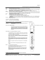
Installing the Exprecium Card
1.
Shut down the computer and remove the AC power cord.
2.
Open the computer case to gain access to the inside. Touch the metal chassis of the computer to drain off any static electricity
before touching a board. Static electricity can damage the components inside a computer or on a printed circuit board.
3.
Locate an empty PCI expansion slot into which you will install the Exprecium card. The selected slot must support PCI Plug &
Play devices. In most recent computers, all PCI slots have this ability. If you are not sure that your PC does, check the
specification manual or contact your PC vendor. Remove the slot cover from the selected PCI slot. Retain the screw from the slot
cover, you will need it to secure the Exprecium Card to the computer chassis.
MCDI Inc.
86 Claude-Champagne Avenue, Montreal, QC, Canada H2V 2X1
Telephone: +514-481-1067
Internet: http://www.mcdi.com
Fax: +514-481-1487
Page 4
Installation guide for Alarm Receiver Exprecium
4.
Remove the card from the anti-static bag. Record its serial number, you may be required to supply it in case of a support call.
Holding the edge of the card, carefully align the edge connector with the expansion slot. Push the board into the slot firmly and
evenly until it is fully seated inside the slot.
5.
Visually inspect the connection. If it does not appear to be correct, remove and re-install the board. Secure the card to the
computer’s chassis using the screw removed in step 3.
6.
You can close the computer case at this point or wait until everything is functioning properly.
Installing drivers and utilities software
DOS users :
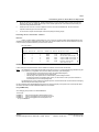
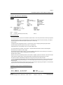
There is no need to install any specific DOS driver. Once you start your computer, the Bios will automatically detect the new
installed PCI card and assign a COM address and an IRQ to each card. Most PC displays a list of PCI devices installed at the power on.
It may be necessary to press the PAUSE key to have a chance to look at it.
Here is an example :
PCI device listing …
Bus No. Device No.
0
0
0
0
0
EXPRECIUM
7
7
9
9
11
Func No.
Vendor ID
1
2
0
0
0
Device ID Device class
8086
8086
6234
6234
1142
7111
7112
0001
0001
643D
IDE Controller
Serial Bus Controller
Simple COMM Controller
Simple COMM Controller
Display Controller
ACPI Controller
IRQ
14
11
15
5
NA
9
Vendor Number : 6234 Device ID : 0001
In above example, two Exprecium Receiver cards are installed. One with IRQ 15 and a second one with IRQ 5.
Notes :
It is possible that your Bios assigns the same IRQ to more than one device. If your DOS application supports IRQ sharing this
is not a problem. If your application does not have the ability to share IRQ’s, try the following steps :
•
•
•
Move the Exprecium card to another free PCI slot to get a different IRQ assignment.
Free more IRQ’s in your system by removing unused cards.
Manually assign to the specific PCI slot a reserved IRQ in your Bios settings and install
the Exprecium in that slot to avoid IRQ conflict. Refer to your PC manual or contact your service technician for
more information on how to manually assign IRQ’s.
The IRQ sharing issue is not a problem when using the Exprecium card under Windows 95 or 98 since Windows is managing
IRQ’s internally and has the ability to share them.
Use the configuration utility called XPRECIUM.EXE, located on the media coming with your Exprecium card, to set the specific options.
See section SETTING UP YOUR EXPRECIUM CARD for more information.
Using COMIRQ utility :
Also a debugging tool is provided. It is called COMIRQ.EXE
To use it, type :
COMIRQ X1
look at incoming signals on the first Exprecium card or
COMIRQ X2
look at incoming signals on the second Exprecium card or
COMIRQ X3
look at incoming signals on the third Exprecium card
… etc. up to COMIRQ X9
MCDI Inc.
86 Claude-Champagne Avenue, Montreal, QC, Canada H2V 2X1
Telephone: +514-481-1067
Internet: http://www.mcdi.com
Fax: +514-481-1487
Page 5
Installation guide for Alarm Receiver Exprecium
Here is an example of display provided by the COMIRQ utility :
COM D400 IRQ 5 : ANY INCOMING SIGNAL
Hit "Space Bar" to send ACK
___________________________________________________________________________________
@<CR>
@<CR>
@<CR>
11:09 02/08 12 1234 51<CR>
11:09 02/08 12 1234 51<CR>
11:09 02/08 12 1234 51<CR>
11:09 02/08 12 1234 51<CR>
@<CR>
11:09 02/08 12 4378 O66<CR>
11:10 02/08 12 4378 O66<CR>
11:10 02/08 12 1234 51<CR>
@<CR>
@<CR>
___________________________________________________________________________________
IRQ Number might Be Available : 3 5 10 11
<ESC> To exit --- <DEL> Clear screen --- Press "A" to enable <ACK>
The top line of the display indicates your Base address and IRQ setting. Press the letter “A” to acknowledge all signals. In the above
example, the COM port address is D400 and the IRQ is 5. This is the information required to configure your DOS software.
Installing Windows 95 drivers :
1.
Power up the computer and allow it to boot into Windows 95. Windows 95 detects that you have added new hardware (Exprecium
receiver card). The New Hardware Found dialog displays : PC SERIAL CONTROLLER. The Add New Hardware Wizard will
detect an : OXCB950 Cardbus UART.
2.
Insert your Exprecium CDROM disk in your CDRON drive and click NEXT to continue.
3.
When asked to : “ Please insert the disk labeled ‘High-performance ports driver disk’ and then click OK “, click OK to continue.
4.
The following message will be displayed : “The file ‘oxmf.vxd’ in high-performance ports driver disk could not be found”, click
BROWSE, in the Drive Section, select your CDROM drive then click OK.
5.
The same dialog box will appear again. This time just click OK. Windows will complete the installation.
For each Exprecium card installed, Windows will create a new COM port starting at COM5 (COM1 to COM4 are reserved for your PC).
The second card will be on COM6, the third one on COM7 and so on ...
Installing Windows 98 drivers :
1.
Power up the computer and allow it to boot into Windows 98. Windows 98 detects that you have added new hardware (Exprecium
receiver card). The New Hardware Found dialog displays : PC SERIAL CONTROLLER. The Add New Hardware Wizard will
detect an : OXCB950 Cardbus UART, click NEXT to continue.
2.
When asked to specify how to install the driver, select SEARCH FOR THE BEST DRIVER FOR YOUR DEVICE, and then click
NEXT.
3.
Insert the CDROM DRIVERS & UTILITIES into the CDROM drive. In the Add New Hardware Wizard box, select
CDROM
DRIVES (as the location for the drivers) and press NEXT. The Install Disk dialog displays :
?:\OXPCI.INF press NEXT.
4.
Windows will copy and install the required drivers for your Exprecium card. Click FINISH to let Windows complete the process.
For each Exprecium card installed, Windows will create a new COM port starting at COM5 (COM1 to COM4 are reserved for your PC).
The second card will be on COM6, the third one on COM7 and so on ...
MCDI Inc.
86 Claude-Champagne Avenue, Montreal, QC, Canada H2V 2X1
Telephone: +514-481-1067
Internet: http://www.mcdi.com
Fax: +514-481-1487
Page 6
Installation guide for Alarm Receiver Exprecium
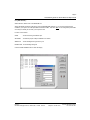
Using WINCOM utility :
Within Windows, double click on the WINCOM icon.
Select SETTINGS and set the COM port to match the EXPRECIUM COM port. If you only have one Exprecium
installed in your system, the COM port address should be COM5. Then click O K . Do not change other parameters
since they are already set to match your Exprecium card.
Function of each button :
OPEN
To start monitoring the selected port.
SETTINGS
To select the proper COM port address to be viewed.
SEND ACK
To acknowledge each signal one by one.
ENABLE ACK To acknowledge all signals
Use the CLEAR SCREEN button to clear the display.
MCDI Inc.
86 Claude-Champagne Avenue, Montreal, QC, Canada H2V 2X1
Telephone: +514-481-1067
Internet: http://www.mcdi.com
Fax: +514-481-1487
Page 7
Installation guide for Alarm Receiver Exprecium
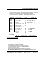
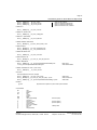
Setting up your Exprecium
There is no switches or jumpers to configure your card. All settings are done using the setup program called XPRECIUM.EXE
( provided on the media coming with your card ). This program works under DOS or Windows and can be executed from any
disk drive. To use it under Windows, your Windows drivers must be installed first and properly configured.
To enter in the configuration menu, type XPRECIUM<enter> Under DOS or Windows, double click on the icon
XPRECIUM.
The following display will appear :
ADDRESS/IRQ
D400
XXXX
XXXX
XXXX
XXXX
XXXX
XXXX
XXXX
XXXX
XXXX
XXXX
XXXX
XXXX
XXXX
XXXX
XXXX
15
yy
yy
yy
yy
yy
yy
yy
yy
yy
yy
yy
yy
yy
yy
yy
<CR> Edit
<CTRL U> UPDATE
Xprecium Parameters
MCDI Inc.
Version : 0.0.9
1067
S.A.M.M. Section
Receiver number
Line 1 number
Line 2 number
Heartbeat
Sescoa SS instead 4x2 sum
3x2 instead 4x1
Clear zero
Compress Extended
Listen In (Empty or 1..F)
Printer / Buzzer
Start Handshake with
Wait after Off Hook
Caller ID to PC
Caller ID to Printer
Caller ID ALL
Date / Time
Send Year
ACK Delay
Sur-gard mode
<ESC> Exit
+(514) 481
: 1
Keep receiver number : No
: 1
Keep line number
: No
: 2
Offset
: 0
: No
Compress Contact ID : No
: No
: No
: No
: No
:
: No
1 = 1400Hz / VFSK
: 1 >>>
2 = SIA / CFSK
: No
3 = DUAL1400Hz/2300Hz
: No
4 = 2300 Hz
: No
5 = STRATEL
: No
6 = TELIM
: YES
7 = ROBOFON
: No
: 1
: No
<F1> Restore default
<F2> Read Config File
Setup program display description and commands
Address / IRQ section
Address part of display shows address fields and IRQ’s setting for all Exprecium receivers installed in PC.
Only the cards installed will appear in the list
Move cursor to desired Exprecium using Up/Down arrows.
Press <Enter> to move to Parameter section on right part of display.
Parameters displayed on the right are actual operating parameters.
Press F1 to restore Factory defined parameters. Press F2 to restore saved parameters.
Press CTRL-U to start the firmware update process. See section FIRMWARE UPGRADE.
Press <ESC> to Exit setup program XPRECIUM.
Before accepting Exit command, XPRECIUM utility request authorization to save new parameters.
Note : When exiting from XPRECIUM setup program, real time clock on ALL Exprecium will be reset to PC time.
MCDI Inc.
86 Claude-Champagne Avenue, Montreal, QC, Canada H2V 2X1
Telephone: +514-481-1067
Internet: http://www.mcdi.com
Fax: +514-481-1487
Page 8
Installation guide for Alarm Receiver Exprecium
Parameter section to the right of Address section
Move cursor to desired parameter using UP/DN arrow. Key in each new parameter .
After all changes have been entered press <ESC> to go back to Address Section.
ONLY in Address Section can changes be saved and sent to receiver.
Parameter definition
Emulation mode easy setting information:
MCDI Mode
Default setting
Ademco 685 Mode
Default setting + Date / Time = NO
Surgard Mode
Surgard = YES
OPTIONS: ( default settings are indicated in bold )
Receiver
Number sent to computer and printer 0 to F
1
Line 1
Number sent to computer and printer 0 to F
1
Line 2
Number sent to computer and printer 0 to F
2
Heartbeat
Yes = enable
No = disable
Heartbeat signals are sent to computer every 30 seconds only in MCDI and Surgard mode.
Sescoa SS
Yes = enable
No = disable
Conflict with Pulse 4X2 Checksum format
3x2 Instead 4x1
Yes = enable
No = disable
Conflict with 4X1 in Compressed Expanded
DO NOT select with Compressed Expanded = YES
Clear Zero
Yes = Zero removed in 3x1 and 4x1 No = zero present
Tells the receiver not to insert a zero in front of the account number and in front of the alarm code, for
incoming 3 x 1 and 4 x 1.
Example:
Compressed/
Extended
3x1
123 4
444 5
Extended compressed in 3 x 2 standard
After compression: 123 45
Example:
3x1
123 1
Standard 3 x 1
Example:
4x1
1234 1
Standard 4 x 1
Example:
3 x 1 and 4 x 1
0123 01 for 3 x 1
1234 01 for 4 x 1
Yes = Compressed extended 3x1 or 4x1
Example:3 x 1
123 4
444 5
without the CLEAR ZERO option:
No = default
Extended compressed in 4 x 2 standard
After compression: 0123 45
Example:4 x 1
Extended compressed in 4 x 2 standard
1234 5
5555 6After compression: 1234 56
Listen-In
(3x1,4x2)
Empty or 1 .. F
Empty
Define code to trigger Listen-In mode in 3x1 or 4x2 formats
Printer/Buzzer
Yes = Check printer on Exprecium port No= Do not check for printer
MCDI Inc.
86 Claude-Champagne Avenue, Montreal, QC, Canada H2V 2X1
Telephone: +514-481-1067
Internet: http://www.mcdi.com
Fax: +514-481-1487
Page 9
Installation guide for Alarm Receiver Exprecium
By default the Exprecium does not verify printer status on parallel port but sends data to be printed as if
a printer was connected to this port.
(Yes) option tells the Exprecium receiver to verify and report on the status of the printer connected to
its parallel port. A connector is supplied to daisy chain multiple receiver cards ( Exprecium, TLR+
or TLR ) in the same computer to send all output to one printer only.
When Check printer option is enabled (Yes) and the computer is absent, each event being sent to
printer triggers a warning buzzer. This warning sound may be stopped by clicking twice the ON-LINE
printer key. Buzzing resumes if printer is left Off-line.
Do not set the "Yes" parameter if no printer is installed. Multiple error messages could be generated
by taking this action.
Start handshake with
1
2
3
4
5
6
7
1400hz / VFSK
SIA / CFSK
DUAL 1400hz / 2300hz
2300hz
STRATEL
TELIM
ROBOFON
Default sequence is as above. Option is to change first element with the one selected.
Extreme care must be exercised when changing Handshake sequence. It is a well known fact that
many dialers do not respond well to all startup sequences.
Wait after O/H
Delay to start Handshake after Off Hook. No = normal, Yes=5 seconds
Caller ID PC
No = Do not send telephone ID data to PC
Yes = Send telephone ID data to PC
Caller ID PRN
No = Do not send telephone ID data to the Exprecium printer port
Yes = Send telephone ID data to the Exprecium printer port
Caller ID ALL
No = Do not send telephone ID data except when bad transmission occurs
Yes = Send telephone ID data to PC and Exprecium printer port unless PRN and PC select otherwise
Date / Time
Yes = enable
Send year
Yes = Date including the year
No = disable
No = Date with out year
Yes, tells the Exprecium to add the Year in date format: HH:mm _ _ MM/DD[/YY] ...
No,tells the Exprecium to use date and time format: MM/DD.
ACK delay
Wait time in seconds for ACK reception before resend. (Surgard/Native mode only)
1 to 9 1= default
Surgard Mode
Yes = enable
No = disable
SAMM Automation software Section
Keep receiver number
No = default
YES = Insert receiver # in front of account #
Keep line number
No = default
YES = Inset line # in front of account #
Offset
0 (zero) = default
Insert digit 0 to 9 or letter A to F in front of account #
Compress Contact ID
No = default
YES = Use Compress Contact ID instead of standard one
Connectors, leds and Jumpers - Main board
J1
J2
J3
JP1
External battery connector 6 - 12 votls
Connector port for IBM compatible parallel printer type DB25. When more than one card is installed in the same computer,
one printer can be used for all cards in the same computer, instead of one printer per receiver card. See TX1,RX1 below.
PCI bus connector
Future use
MCDI Inc.
86 Claude-Champagne Avenue, Montreal, QC, Canada H2V 2X1
Telephone: +514-481-1067
Internet: http://www.mcdi.com
Fax: +514-481-1487
Page 10
Installation guide for Alarm Receiver Exprecium
JP5
JP6
JP8
JP10
TX1, RX1
PWR1
S1
D1 & D2
Processor jumper pin 2-3 (do not remove)
Line 2 Phone connector type RJ11. Connect Green and Red only on each connector
Dry contacts relay normally open or close contacts activated for 1 second when an event is received. Can be used to trigger
external devices. Pins : 1&2 Normally Open / 2&3 Normally Closed ( card in operation )
Maximum rating : 110V DC or 125 V AC / 1A
UL/CSA rating : 30V DC / 1A 110V DC or 125V AC / .3 A
Serial communication or MRD1000 Remote Display.
Connectors for chaining more than one Exprecium card. This allows only one external printer to serve all receiver cards.
When more than one receiver card is installed, use a jumper to link all receiver cards. Connect TX1 of the first card to RX1
of the second card. Connect your printer on the last card having only a jumper on RX1.
For MRD1000 remote display power feed.
Reset switch for the receiver. Two options are available.
1. Soft Reset: Press once to reset the receiver to the user’s configuration.
2. Cold Reset: Press once and wait for beep. During the beep press once more.
Soft and Cold Reset can also be software achieved by running XPRECIUM setup program as shown in Setting up your
Exprecium .
Both leds are ON to indicate power from the PC. Only Led D2 is ON when PC is OFF and the Exprecium is powered by
an external source on J1.
Connectors - Communication Interface Module
JP1,2,3
Connectors to connect to the Main Board
Physical characteristics of the Exprecium Physical characteristics of Exprecium
Size :Size
Receiver has all out dimensions, including bracket of 20.3x12.7
cm or 5x8 inches.
Buffer memory :Buffer memory
Buffer holds up to 1800 events in a non volatile
Card keeps printing during fail time if 6 volt external battery is
connected and charged. When computer comes back on, buffer
empties to the computer. If more than 1800 events are received
in the buffer during fail time, card writes over the oldest event.
Written records may be available on printer connected to parallel
printer port.
External battery connectorrExternal battery connector
A six (6) volt battery connector is designed to feed receiver if computer fails.
A 3 foot wire is supplied. Connect the red wire to the positive side and the
black wire to the negative side of the battery.
During normal operation, card takes its power from computer and maintains
battery charge. When computer fails, card takes its power from battery and
keeps on receiving alarms.
Battery size (power) is dependent on the period it must maintain the receiver
operating while PC is off. As a rule of the thumb, define the number of hours
a fully charged battery must support the system and divide by two (2) to get
the A-H.
Example: To support the receiver for 8 hours requires a 4 A-H rechargeable
battery.
Battery type recommended: Rechargeable sealed lead-acid for constant
voltage.
Buzzer
Alert/WarningBuzzer Alert/Warning
On board buzzer is available for alert warning when Computer is absent.
Enable if setup parameter Check printer is set to Yes.
Is activated (start buzzing) by event to be printed on the Exprecium printer
port.
Stop buzzing by pressing twice (2) ON-LINE printer key. Refer to printer
connected to the Exprecium parallel printer port. Will resume buzzing if
printer is left off-line.
Formats and characters transmitted Formats and characters
MCDI Inc.
86 Claude-Champagne Avenue, Montreal, QC, Canada H2V 2X1
Telephone: +514-481-1067
Internet: http://www.mcdi.com
Fax: +514-481-1487
Page 11
Installation guide for Alarm Receiver Exprecium
Formats and characters transmitted
Receiving
Formats
MCDI
Acron
Ademco L/S expanded
Ademco Old
Franklin Fast
Radionics Expanded
Sescoa SS
CFSK III
SurGard
DTMF
Ademco Contact ID
Ademco Fast / High Speed
DCI
Napco
Scantronic
SIA I - II - ~III
Varitech VFSK
Robofon
Pulse
10,20,40 bps 3x1 - 4x1 - 4x2
10,20,40 bps 4x2
10,20,40 bps 3x1 - 4x1 Extended
Frequencies
Handshake and kissoff:
DTMF
10 char/sec.
FSK
110 bauds or 300 bauds (SIA, CFSK, VFSK)
FSK
Ademco L/S Standard
Ademco Express
FBI Super Fast
Radionics Standard
Sescoa standard
Silent Knight Slow/Fast
Stratel
Telim
Dual Round
Checksum
Dual Round
1800 Hz / 1900 Hz
1400hz / 2300hz
Bell 103
Listen-in, Two way voice
Listen-in function
Some alarm panels offer the option for the Central station operator to listen for sound in the premises where the alarm signal originates.
Alarm panels supporting “Listen-in” keep the telephone line open after having sent a signal, to allow sound monitoring. The telephone
line will be closed by the Central station subject to operator action or receiver setup.
Listen-in criteria
The Exprecium receiver is triggered into “Listen-in” mode for incoming events according to panel setup for specific formats.
SIA and Contact ID formats have specific codes for Listen-in. See Panel setup.
DTMF formats use the AEx signal where x can be 0 to F at the Installer’s choice.
3x1 and 4x2 formats have no standard codes for Listen-in. Exprecium allows home selection of Listen-in codes at Setup time.
Receiver action upon reception of “Listen-in” trigger
Upon reception of event in the Listen-in category, the receiver maintains the telephone line open for a period of up to 180 seconds or
less then 180 seconds upon reception of any telephone tone from the keypad.
Operator control for “Listen-in”
Operator must be warned by Monitoring software of account “listen-in” capability. Operator has a maximum of 180 seconds from time
of alarm reception to telephone pickup. Failure to pickup telephone in this delays will cause line hang-up by the receiver.
Once the line is seized by Central station local telephone, the hang-up action of the receiver will have no effect.
To close communication with alarm signal site in the first 180 seconds when the Exprecium receiver is in action, operator must press
any key on the telephone keypad before hanging up. The receiver will hang up before 180 seconds only upon reception of a tone from
telephone keypad.
To close communication with alarm signal site after 180 seconds of event reception, simply hang-up the telephone. This is because the
Exprecium receiver is not in function anymore, its delay having expired.
Transmission to computer and printer in EXPRECIUM MCDI mode
Pulse, DTMF, FSK
FORMAT 3x1, 4x1
HH:mm_ _MM/DD[/YY] _ _ RL_CCCC_ØA<CR>
HH:mm_ _MM/DD[/YY] _ _ RL_CCCC_A<CR>
MCDI Inc.
86 Claude-Champagne Avenue, Montreal, QC, Canada H2V 2X1
Default
Option 4x1 set by INITLR
Telephone: +514-481-1067
Internet: http://www.mcdi.com
Fax: +514-481-1487
Page 12
Installation guide for Alarm Receiver Exprecium
HH:mm_ _MM/DD[/YY] _ _ RL_CCC_A<CR>
HH:mm_ _MM/DD[/YY] _ _ RL_ØCCC_AZ<CR>
HH:mm_ _MM/DD[/YY] _ _ RL_CCCC_AZ<CR>
Option 3x1 set by INITLR
Option 3x1 extended compressed 4x2
Option 4x1 extended compressed 4x2
Option zero removed 3x1,4x1, extended
FORMAT 4x2
HH:mm_ _MM/DD[/YY] _ _RL_CCCC_AZ<CR>
FORMAT 4x3 (SESCOA SS)
HH:mm_ _MM/DD[/YY] _ _RL_CCCC_AZZ[Z]<CR>
FORMAT 4x3 (SUR GARD)
HH:mm_ _MM/DD[/YY] _ _RL_CCCC_AZZ<CR>
FORMAT ADEMCO HIGH SPEED
HH:mm_ _MM/DD[/YY] _ _RL_CCCC_AAAA_AAAA_A<CR>
FORMAT ACRON
HH:mm_ _MM/DD[/YY] _ _RL_CCCC_AAAAAAAA<CR>
HH:mm_ _MM/DD[/YY] _ _RL_ _CCC_AAAAAAAA<CR>
FORMAT FBI SUPER FAST
HH:mm_ _MM/DD[/YY] _ _RL_CCCC_E ZZ<CR>
FORMAT CONTACT ID
HH:mm_ _MM/DD[/YY] _ _RL_CCCC_18_TAAA_GG_ZZZ<CR>
FORMAT MODEM SIA
HH:mm_ _MM/DD{YY}] _ _RL _ [#CCCCCC|EAAZZZ/AAZZZ/AAZZZ]<CR>
<LF>RL_ [#CCCCCC|EAAZZZ/AAZZZ/AAZZZ]<CR>
FORMAT MODEM CFSK / VFSK
Native mode
Ademco685 Emulation
(same as 4x2)
HH:mm_ _MM/DD{/YY} _ _ RL_CCCC_AZ<CR>
CALLER ID
Phone signal added to event code. Examples
HH:mm_ _MM/DD[/YY] _ _RL_CCCC_AZ{t...t}<CR>
HH:mm_ _MM/DD[/YY] _ _RL_CCCC_18_TAAA_GG_ZZZ {t...t}<CR>
HH:mm_ _MM/DD{YY}] _ _RL _ [#CCCCCC|EAAZZZ/AAZZZ/AAZZZ]{t...t}<CR>
Added to 4x2
Added to Contact ID
Added to SIA
Heartbeat
@<CR>
Signal sent to the computer every 30 seconds if option is enabled
Code definitions
HH
:
mm
DD
_
__
MM
[YY]
/
R
L
C
A
E
Z
G
:
:
:
:
:
:
:
:
:
:
:
:
:
:
:
:
Hour
Character ":"
Minute
Day
1 space
2 spaces
Month
Year [Present/Absent]
Character "/"
Receiver number
Line number
Account number
Event code or modifier
Zone type
Zone
Group (Partition)
MCDI Inc.
86 Claude-Champagne Avenue, Montreal, QC, Canada H2V 2X1
Receiver Option)
(Receiver Option)
(Receiver Option)
FBI super Fast
Telephone: +514-481-1067
Internet: http://www.mcdi.com
Fax: +514-481-1487
Page 13
Installation guide for Alarm Receiver Exprecium
T
Ø
<CR>
<ACK>
@
t...t
[
]
|
#
E
/
<LF>
:
:
:
:
:
:
:
:
:
:
:
:
:
Type(E or R)
Zero
EOS
Data retransmits to computer every 2 second
Heartbeat signal
Telephone number from Caller ID
Beginning data delimiter (SIA)
Ending data delimiter (SIA)
Field separator (SIA)
Account ID block code (SIA)
Function block code (SIA)
Data code packet separator (SIA)
Line Feed
(Contact ID)
(Carriage Return)
until ACK is received (ACK=06H or $06).
Receiver Option)
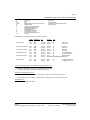
EXPRECIUM Error and Warning messages sent to Printer port and PC:
HH:MM
MM/DD[YY]
RL
Account
XYY
Printer message
Time
Time
Date
Date
Receiver
Receiver
account
account
01
02
Printer error
Printer reset
Telephone line monitoring
Time
Time
Date
Date
Receiver
Receiver
account
account
03
04
Error Line 1
Reset Line 1
Telephone line monitoring
Time
Time
Date
Date
Receiver
Receiver
account
account
05
06
Error Line2
Reset Line2
External battery backup
Time
Time
Date
Date
Receiver
Receiver
account
account
07
08
Low external battery
Normal external battery
Transmission message
Time
Time
Date
Date
Receiver
Receiver
0000
00
Bad transmission
[#0000|A BAD TRANSMISSION]Format SIA
No Transmission
Time
Time
Date
Date
Receiver
Receiver
0000
0000
F1
F2
No signal received Line 1
No signal received Line 2
Transmission to computer and printer in ADEMCO 685 / Surgard emulation mode
User Manual : for information on transmission See ADEMCO 685 standards
User Manual : for information on transmission See Surgard MRL2 documentation
Surgard emulation applies to Dial up Alarm signals and Telephone ID
Messages from EXPRECIUM printer port:
When computer ceases to communicate, "Computer absent" message is sent to the Exprecium printer port
When computer resumes communication, "Computer restore" message is sent to to the Exprecium printer port
Transmission rate
1200 bps, no parity, 8 bits, I stop bit
MCDI Inc.
86 Claude-Champagne Avenue, Montreal, QC, Canada H2V 2X1
Telephone: +514-481-1067
Internet: http://www.mcdi.com
Fax: +514-481-1487
Page 14
Installation guide for Alarm Receiver Exprecium
Warranty
The Electronic products of MCDI Inc. are under a five year limited warranty. Material is repaired or exchanged, free of charge, when
returned to MCDI service points, post paid. Abused or misused equipment is not covered by this warranty. Power surge damages
are not covered by warranty.
Legal compliance and Warning
United States Regulation FCC Warning
Radio/TV interference
This device is not equipped with dialing equipment.
Telephones equipped with electronic dialing keys generate and use radio frequency energy, and if not installed and used properly and in
strict accordance with the manufacturer's instructions, may cause interference to radio and television reception.
NOTE: This device has been tested and found to comply with Part 15 if the FCC rules. Operation is subject to the following two
conditions:
1.
2.
This device may not cause harmful interference and
This device must accept any interference received, including interference that may cause undesirable operation.
If your device causes interference, one of the following measure may correct the problem:
.
.
.
Reorient or relocate the receiving TV or radio antenna, when this may be done safely.
To the extent possible, move the device and the radio or television farther away from each other, or connect the computer with the
device and the radio or television to outlets on separate circuits.
Consult the dealer or an experienced radio/television technician for additional suggestions.
NOTE: FCC registration does not constitute an expressed or implied guarantee of performance.
Right of the Telephone Company
If this device causes harm to the telephone network, the telephone company may stop your service temporarily or ask you to remove your
equipment until the problem is resolved. If possible, they will notify you in advance. If advance notice is not practical, you will be notified
as soon as possible and be given the opportunity to correct the situation. You will also be informed of your right to file a complaint with the
FCC.
Your telephone company may make changes in its facilities, equipment, operations or procedures that could affect the proper function of
this device. If they do, you will be notified in advance to give you an opportunity to maintain uninterrupted telephone service.
Federal communication commission (FCC) Notice
FCC Registration Number: This device complies with Part 68, Rules and Regulations, of the FCC for direct connection to the Public
Switched Telephone Network (the FCC registration number and REN number appear on a sticker). If requested, this information must be
provided to the telephone company.
Your connection to the telephone line must comply with these FCC rules:
.
Use only an FCC standard RJ11W/RJ14W or RJ11C/RJ14C network interface jack and FCC compliant line cord and plug to
connect to the telephone line. (To connect the device press the small plastic tab on the plug at the end of the telephone's line cord.
Insert into a jack until it clicks. To disconnect, press the tab and pull out.)
.
If a network interface jack is not already installed in your location, you can order one from your telephone company. Order
RJ11W/RJ14W for wall mounted telephones or RJ11C/RJ14C for desk/table use. In some states, customers are permitted to
install their own jacks.
.
This device may not be connected to a party line or coin telephone line. Connection to Party Line Service is subject to state tariffs
(contact the state public utility commission, public service commission or corporation commission for information).
.
It is no longer necessary to notify the telephone company of your device's Registration and REN number however, you must provide
this information to the telephone company if they request it.
.
If trouble is experienced with this equipment, for repair or warranty information please contact:
Local dealer or
MCDI
86 Claude-Champagne Avenue., Montreal, QC, Canada H2V 2X1
Telephone: +(514) 481-1067 Fax: +(514) 481-1487
MCDI Inc.
86 Claude-Champagne Avenue, Montreal, QC, Canada H2V 2X1
Telephone: +514-481-1067
Internet: http://www.mcdi.com
Fax: +514-481-1487
Page 15
Installation guide for Alarm Receiver Exprecium
.
.
If the equipment is causing harm to the telephone network, the telephone company may request that you disconnect it until the
problem is resolved.
This device does not have any serviceable parts. Repair or exchange must be made by the manufacturer or its representatives.
Signaling method: This device does not dial out.
Ringer Equivalence Number: The FCC Registration label (on the device) includes a Ringer Equivalence Number (REN) which is used
to determine the number of devices you may connect to your telephone line. A high total REN may prevent telephones from ringing in
response to an incoming call and may make placing calls difficult. In most areas, a total REN of 5 should permit normal telephone
operation. To determine the total REN allowed on your telephone line, consult your local telephone company.
Hearing aids This device does not convert the signal for human hearing.
Programming Emergency numbers: This device does not dial out.
Important safety instructions
When using the device, basic safety precautions should always be followed to reduce risk of fire, electrical shock and injury to persons
including the following:
1.
2.
3.
4.
5.
6.
Read and understand all instructions.
Follow the warnings and instructions marked on the product.
This device is installed in a computer. This work should be done by a qualified computer technician.
Avoid using during electrical storm. There may be a remote risk of electrical shock from lightning.
CAUTION: Do no use sharp instruments during installation procedure to eliminate the possibility of accidental damage to the
device, the computer or the cord.
Save these instructions.
Europe EC Declaration of Conformity
We:
MCDI Inc.
86 Claude-Champagne Avenue
Montreal, QC
Canada H2V 2X1
Declare under our sole legal responsibility that the following products conform to the protection requirements of council directive
89/336/EEC on the approximation of the laws of member states relating to electromagnetic compatibility, as amended by directive
93/68/EEC:
MCDI-EXPRECIUM alarm receiver
The products to which this declaration relates are in conformity with the following relevant harmonised standards, the reference numbers
of which have been published in the Official Journal of the European Communities:
EN50082-1:1992 --- EN55022 CLASS A --- EN 60555 PARTS 2 & 3 ---EN41003:1993 --- BAPT Note 48 revision 5
EN60950/IEC Ed 2 Amendment No1 1992, Amendment No2 1993, Amendment No3 1996
MCDI Inc.
Europe EN41003 Warning Application Note 48, Issue 5
1) The power required by the host and the total of all adapter cards installed within the host environment, together with any auxiliary
apparatus, shall not exceed the power specification of the host apparatus.
The power requirements for the EXPRECIUM receiver are:
From computer
From External Battery (standby)
Charging Voltage
12V
6V
6.7 Volts
200 mA max.
500 mA
500 mA (Current Limit)
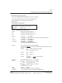
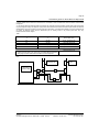
2) It is essential that, when other option cards are introduced which use or generate a hazardous voltage, the minimum creepages and
clearances specified in the table below are maintained. A hazardous voltage is one which exceeds 42.4V peak a.c. or 60V d.c. If you have
any doubt, seek advice from a competent engineer before installing other adapters into the host equipment.
3) The equipment must be installed such that with the exception of the connections to the host, clearance and creepage distances shown
in the table below are maintained between the card and any other assemblies which use or generate a voltage shown in the table below.
The larger distance shown in brackets applies where the local environment within the host is subject to conductive pollution or dry non-
MCDI Inc.
86 Claude-Champagne Avenue, Montreal, QC, Canada H2V 2X1
Telephone: +514-481-1067
Internet: http://www.mcdi.com
Fax: +514-481-1487
Page 16
Installation guide for Alarm Receiver Exprecium
conductive pollution which could become conductive due to condensation. Failure to maintain these minimum distances would invalidate
the approval.
4) The analogue telecommunications interface is intended to be connected to telecommunication network voltage (TNV) circuits which
may carry dangerous voltages. The telephone cord(s) must be disconnected from the telecommunications system until the card has been
installed within a host which provides the necessary protection of the operator. If it is subsequently desired to open the host equipment for
any reason, the telephone cord(s) must be disconnected prior to effecting access to any internal parts which may carry
telecommunication network voltages.
Table:
Clearance (mm)
Creepage (mm)
X
Y
Voltage Used or Generated by
2.0
2.4 (3.8)
Up To
2.6
3.0 (4.8)
Up To 125 Vrms or Vdc
Host or Other Cards
50 Vrms or Vdc
4.0
5.0 (8.0)
Up To 250 Vrms or Vdc
4.0
6.4 (10.0)
Up To 300 Vrms or Vdc
For a host or other expansion card fitted in the host, using or generating voltages
greater than 300V (rms or dc), advice from a competent telecommunication
safety engineer must be obtained before installation or relevant equipment
Above 300 Vrms or Vdc
Host:
TLR or TLR+ or
Exprecium card
Power Supply Unit
or other source of
excessive voltage
X
Expansion
Card
X
Y
Y
MCDI Inc.
86 Claude-Champagne Avenue, Montreal, QC, Canada H2V 2X1
Telephone: +514-481-1067
Internet: http://www.mcdi.com
Fax: +514-481-1487
Technical data sheet for “EXPRECIUM” PCI Twin Line Receiver
Description
Features
“EXPRECIUM” is a full format PC-based twin-line alarm
receiver card.
•
•
•
•
•
•
•
•
•
•
•
•
•
EXPRECIUM connects to PCI bus of a PC Computer. Its
small size fits table top IBM PCs or compatible PC Pentium
and up. EXPRECIUM interfaces to two telephone lines,
imposing no limit to the number of customers per line. It
provides a parallel printer port for direct output without going
through PC.
With large size memory, fast modem circuit, improved PC
bus interface and Caller ID option, EXPRECIUM adds a new
dimension to Alarm Receiving and PC integrated Monitoring
Station.
All MCDI’s PCB receivers work even if PC is down.
external battery power is provided, naturally.
If
Option: Remote display / control unit. Packaged as stand
alone device or fitted in PC’s CD anchor slot.
Certification
Made for PCI bus connection
Easy to install:Plug & play and Hot swap.
Supports SIA, CFSK, BFSK, VFSK, Etc.
Caller Identification (Option)
Internal buffer 1800 Events
Non Volatile Memory
Dead line detection
Up to 12 receivers or more per PC
Alert/Warning buzzer
Supervision of chargeable back-up battery
Selectable Monitoring software interfaces
Listen-in, Two way voice
Remote control and display (option)
FCC(USA), IC(Canada), CE-Security (Europe),
CE-0560 Telecom (Europe)
Specifications
Communications:
Power Requirements:
EXPRECIUM provides 2 RJ11 type jacks for telephone
line connection.
Type
Reception Speed
Handshake and Kiss-off
Pulse Frequency
Telim//Robofon
:
:
:
:
:
Pulse, DTMF, FSK
10, 20, 40 pps DR / CS
1400Hz / 2300Hz/2225Hz
1800Hz / 1900Hz
1180Hz / /1100Hz
Reception Formats supported:
Acron
Radionics 6500
Ademco:
Radionics extended
- Slow/Fast;
Sescoa Slow, Super Fast
- Contact ID;
Sescoa Standard
- Extended;
SIA
- Express;
Contact ID
- High Speed
- compressed & Extended
CFSK,BFSK,
Silent Knight Slow
VFSK
MCDI-Take-a-look
SurGard
FBI Super Fast
Napco Point ID
3x1
3x1 extended
4x1
3x1 extended compressed 4x2
4x1 extended
4x1 extended compressed 4x2
4x2
Zero removed 3x1, 4x1, extended.
Optex’s Varitech
C&K: Bell 103A2 or CCIT ( option)
For Germany and Scandinavia (option):
Telim
Robofon
Printer Output:
Standard DB25 connector for Centronics Parallel
Interface.
Card linking arrangement allowing one printer to serve
all MCDI PCB receivers in one PC.
Event Logging when PC is absent:
EXPRECIUM can store over 1800 events in standby
operation when PC is down.
From computer +12V Supply:
From 6V Battery (standby):
200 mA max.
500 mA
Size and weight:
8” / 20.3 cm (L) x 5” / 12.7 cm(H); 0.484 lb / 220 gr
Station Requirements:
IBM™ or Compatible Pentium™ computer and up. Table
top size enclosure. PCI bus. DOS or Windows
Printer with Centronics parallel interface and cable with
DB25 connector.
PC addressing:
PCI bus. Plug & Play. PC must have Plug & Play BIOS.
Battery Back-up:
EXPRECIUM provides charging and supervision circuitry
for an external 6-Volt battery (not supplied). 12v battery
may be used but no charging will occur.
Charging Voltage
Charging Current Limit
6.7 volts
500 mA
Monitoring Software:
EXPRECIUM interfaces with Monitoring software in
Native mode, Ademco™ 685 emulation mode and
SurGard™ MLR2 emulation mode.
Optional remote control MRD1000:
• Displays incoming signals or controls on 2 lines by 20
characters.
• Configures and operates EXPRECIUM, TLR+ or SATLR+.
• Alarm acknowledge key for easy operation.
• Power fed by EXPRECIUM, TLR+ or SA-TLR+ .
• External self contained unit or Mounted in PC’s CD slot.
V000911
MCDI Inc.
86 Claude-Champagne Avenue, Montreal, QC, Canada H2V 2X1
PH: +514-481-1067
Internet: http://www.mcdi.com
FX: +514-481-1487