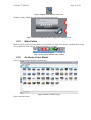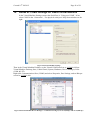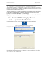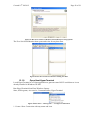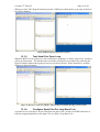
1
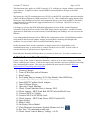
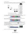
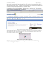
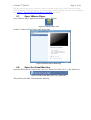
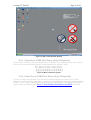
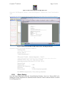
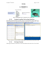
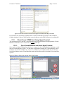
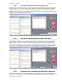
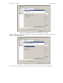
Created 19th Jul 2012
Page 1 of 39
Instructions for Connecting and Using
A Chinese MB STAR Diagnosis System (SDS) C3
BenzWorld Member: ricebubbles
Table of Contents
1.
2.
3.
4.
5.
6.
7.
8.
9.
10.
11.
12.
13.
Revisions ................................................................................................................................ 1
Acknowledgement ................................................................................................................. 1
Introduction........................................................................................................................... 1
Quick Connection Summary................................................................................................ 2
Introduction........................................................................................................................... 3
Research and Experimentation ........................................................................................... 4
SDS Serial Data Configuration............................................................................................ 6
Where to Connect SDS ......................................................................................................... 9
Detailed Instructions for Connecting and Starting SDS ................................................... 9
Tips For Using SDS......................................................................................................... 21
Annex A: PCMCIA and COM2 Settings on Host........................................................ 22
Annex B: COM2 Settings on Guest Virtual Machine.................................................. 26
Annex C: Fault Finding SDS Software and MUX ....................................................... 27
1. Revisions
Version 01: 19th July 2012 (Original document.)
2. Acknowledgement
Benz World Members, especially MBSL550, Noodles, eric242340, Ne3M, Okiebenz, bhatt,
Mackhack, Diesel_Benz, grinich, robledoch, BenzModz et alia and Taztheman at JCRecordings
Software Forum.
http://www.benzworld.org/forums/r230-sl-class/1573730-chinese-mb-star-scanners.html
http://www.jcrecordings.com/index.php?option=com_kunena&func=view&catid=3&id=9201&It
emid=571#9201
3. Introduction
This document is part of my SDS quartet of documents which I produced after months of
research and experimentation with a Chinese SDS.
• SDS What is it.
• SDS Instructions For Connecting and Using
• SDS Software Installation Instructions
• SDS Transfer From External HDD to Internal HDD
I do not profess to be an expert in SDS, far from it, but I do find that keeping the important
information in one or two documents in as simple a form as possible helps me in future when I
have a need to revisit the subject. It may therefore be of use to other BenzWorld members. As
always any feedback is much appreciated.
A few weeks after getting my Chinese STAR Diagnosis System (SDS) Compact3 (C3) setup and
talking to my car it stopped working. It took me two months to recover from this problem and
for many weeks I thought that the MUX had failed. It turned out not to be the MUX but a
combination of hardware (PCMCIA Card), software (Xentry expired date) and configuration
(Host and Guest COM2) issues.
Created 19th Jul 2012
Page 2 of 39
This document only applies to a SDS Compact3 (C3) working on a laptop without a connection
to the Internet. It applies to either external HDD or internal partition storage of the SDS
application.
My laptop now ONLY communicates to my W220 via the RS232 serial data connection and the
vehicle On-Board Diagnosis (OBD) connector (X11/4). I have disabled the laptop Internet link.
During my fault finding activities the most important discovery was that the RS232 data link is
temperamental if operated at the suggested baud rate of 115,200 bps. My SDS is now very
reliable at 9,600 bps.
I am happy to just use the SDS Workshop Information System (WIS), and the Diagnosis
Assistance System (DAS) accessed via the SDS Xentry master application. Another favourite
application is StarFinder accessed from the Virtual Desktop, but nothing I use now accesses the
Internet.
I now understand the Internet side of SDS but the configuration of the Virtual Machine and the
associated IP and Network Adapter settings are particularly confusing and fraught with
problems. In my scenario I don’t need this functionality anyway.
In this document I have tried to summarise in simple terms how to fault find a serial
communication issue, as well as how to connect and how to use a SDS. It took weeks of
research and a lot of trial and error to figure this out.
Hopefully this document will help others to reconnect to their cars. It seems a common issue.
4. Quick Connection Summary
I print a copy of this ‘Quick Connection Summary’ and use it as an aid to setting up my SDS
before each diagnosis session. I follow the steps exactly and have not had a problem connecting
since instigating this regime. The steps are explained in more detail in Section ‘Detailed
Instructions for Connecting and Using SDS’.
1. Connect Charger.
2. Turn off Wireless and/or Ethernet.
3. Start Laptop.
4. Set Laptop Date to January 2012 (One Month After SDS Date).
5. Connect SDS HDD to USB (Only If Required).
6. Insert RS232 Cardbus Serial Adapter.
7. Open VMware Player.
8. Open the Virtual Machine.
9. Check Virtual Machine Date is January 2012.
10. Check Laptop - MUX Link Red, MUX Unlocked Red Cross.
11. Connect MUX to Vehicle.
12. Connect MUX to PCMCIA Card.
13. Check Laptop - MUX Link Green, MUX Unlocked D.
14. Open Xentry.
15. Make Coffee.
16. On Xentry Select Model.
17. Click Diagnosis Assistance Symbol (Button on Left).
18. See Tab + Alt information and wait.
19. Check Green Vehicle Battery Voltage >12.4V.
Created 19th Jul 2012
Page 3 of 39
20. Perform Quick Test.
21. Delete Stored Faults.
22. Shut Down DAS.
23. Close Xentry.
24. Power Down Virtual Machine.
25. Remove Cable from Vehicle.
26. Remove MUX Cable from RS232 Cardbus Adapter Card.
27. Remove RS232 Cardbus Adapter Card from Laptop PCMCIA Slot.
28. Remove External HDD from Laptop USB Port (Only If Required).
29. Power Off the Laptop.
5. Introduction
I purchased a Chinese MB STAR Diagnosis System (SDS) Compact3 (C3) on the Internet purely
for educational purposes and so that I could experiment with some of the settings in my W220
S500, especially to do with my pet subject, the Automatic Climate Control (ACC).
Figure 1 As Purchased MB STAR Diagnosis System Compact3
What I received was:
• 1x MULTIPLEXER
• 1x 16pin OBD II cable
• 1x 4pin cable
• 1x 38 pin cable
• 1x 14pin track cable
• 1x COM cable
• 1x RS232 to RS485 Cable
• 1x Serial adapter cable
• 1x PCMCIA RS232 Cardbus Adapter Card and Pamphlet.
• 1x Hard Drive Disc for DAS, EPC and WIS V2011.11, FINDER V2011.11.
Purchasing, owning, setting up and using a SDS has turned out to be an extremely difficult
project and one not to be undertaken lightly. There is a plethora of information available on SDS
on the Internet but unfortunately it is mostly non constructive, quite often abusive, and fairly
often not available without paying a fee to some very enterprising people.
My SDS as supplied came without any installation instructions other than a couple of crude
videos and an out of date pamphlet for the RS232 Card.
After a lot of assumptions and several emails to the supplier, I eventually got connected and
began cautiously testing the various functions and capabilities of SDS. I particularly like the
Workshop Information System and the StarFinder applications and have used them many times
to date. I have yet to have a real need to use DAS but began self training just in case, and
Created 19th Jul 2012
Page 4 of 39
progressed to the point where I could exercise the cabin lights (easy to watch from outside the
vehicle) and got to the stage of opening and closing various flaps on the ACC. I was able to read
out the list of fault codes stored in my vehicle and was surprised to find a transmission issue
which has been there for several years.
I then learnt the hard way that installing and switching on the SDS on a laptop connected to the
Internet results in the system automatically downloading SDS “Addons” and in the process, it
seems, being “Black Listed” by MB thus preventing the MUX from working/connecting.
I could still use Xentry in simulation mode, ie with no vehicle connected, and this is extremely
useful for training purposes, but I just could not get the SDS to connect again to my vehicle.
It took me two months of full time research and experimentation in order to recover from my
predicament. I then ran into the problem that it seems all Chinese Star C3 SDS have in that they
are prone to cease working three months after the date of the SDS Version. In my case an
application or “patch” was provided which reset the SDS software. My guidelines should avoid
the need to do this in future as I now always configure the laptop date at my SDS Version plus
one month, at the start of each session.
My most important and unexpected discovery was that the RS232 data link is temperamental if
operated at the recommended baud rate of 115,200 bps. It seems that the MUX provided could
not cope with these high data rates. My SDS worked at 57,600 bps but to be on the safe side I
have set host and guest COM2 settings to 19,200 9,600 bps and the SDS is now very reliable and
connects every time. (Later note: I now have set COM2 baud rate to 9,600 bps as it seems even
more stable. I couldn’t be bothered changing all the figures. I just replaced ‘19,200’ with
‘19,200 9,600’ throughout the document.)
I also think the order in which you connect is important and I have slightly adapted a procedure
suggested by Taztheman.
6. Research and Experimentation
If you are interested in how I got my SDS going again see Annex C: Fault Finding SDS Software
and MUX.
The critical things to do are listed here and in the ‘Detailed Instructions for Connecting and
Using SDS’ Section.
After recovering from the classic “software time expired fault” which occurs when opening
Xentry after three months of use, I found that I could not connect to my vehicle. Once the
Virtual Desktop is running, a simple easy test for proper connectivity is to connect to the vehicle
and turn on the ignition. Then run STAR Utilities, Self Diagnosis, Caesar Self Diagnosis and
inspect the result. A ‘good’ result looks like this.
Created 19th Jul 2012
Figure 2 SDS STAR Utilities Caesar Test on 2003 W220 - Good
A Caesar Test on a later model (2008 W204) is much more comprehensive.
Figure 3 SDS STAR Utilities Caesar Test on 2008 W204 - Good
A ‘bad’ result looks like this.
Figure 4 SDS STAR Utilities Caesar Test on 2003 W220 - Bad
Page 5 of 39
Created 19th Jul 2012
Page 6 of 39
The SDS, SDconnect Toolkit, Information function also showed “No signal” from my ‘Part D’
MUX. The ‘06’ MUX is a legacy from my initial connection.
Figure 5 SDS SDconnect Toolkit MUX D No Signal
In my initial ignorance I spent weeks reading up on Virtual Machines, Network Adapters and
Bridged Connections, and experimenting with IP/TCP configurations, eventually to realise that
these were not important for a simple RS232 data link via a cable between the SDS and the car.
If you are interested in connecting to the Internet, one of my critical findings was that in the
Virtual Machine Desk Top, Folder “Info”, it lists IP Addresses which cannot be used in SDS as
being, 172.29.127.0 to 172.29.127.255. From the supplied video instructions I had been using
172.029.127.123 which would not work properly. It was a lot better using 172.129.127.123.
Why I do not know and gave up further research as in my situation the IP settings are irrelevant.
What were important were the serial data port settings and I have included a section on how to
set them up as this was critical to the successful operation of my SDS and MUX. See Annex A:
PCMCIA and COM2 Settings on Host and Annex B: COM2 Settings on Guest Virtual Machine.
7. SDS Serial Data Configuration
Remember these instructions are for starting the SDS Software on a Virtual Machine already
installed on a stand alone Laptop, and for checking that the SDS is connected and working.
My SDS Software is Release: R2.0, V 11/2011, (2011-11-09). Reference SDS STAR Utilities.
Figure 6 SDS STAR Utilities Version Information
Created 19th Jul 2012
Page 7 of 39
In my configuration the SDS Software is installed on an external USB hard disk drive and the
MUX is connected by a RS232 Cardbus Adapter inserted in the Laptop PCMCIA slot.
Figure 7 SDS STAR Diagnosis System (SDS) and OBD II Connector
In my configuration, once the MUX is connected to the laptop and the car and the green light is
on, the Virtual Machine Desktop ‘Desk Band’ icons look like this. (Explained later.)
Figure 8 SDS Virtual Machine Desk Band Icons MUX Unlocked
Then once Xentry is opened and is communicating with the car the ‘Desk Band’ MUX icon
changes from Unlocked to Locked.
Figure 9 SDS Virtual Machine Desk Band Icons MUX Locked
The Host, Windows, Laptop, PCMCIA, External Slot contains a Compact Flash OX16CF950
Cardbus Adapter configured as a Serial Port (COM2) with 19,200 9,600 bps baud rate and
14.7456 MHz crystal frequency.
(Note the supplied Pamphlet states to use 115,200 bps and a Crystal Frequency of 1.8432MHz
with a “Baud rate divider (prescaler)” of 8.625. The baud rate was confirmed by the SDS
Supplier, but I found these figures didn’t work for some reason.)
Figure 10 Compact Flash OX16CF950 Cardbus Adapter (COM2)
My MUX is a Type D employing automatic configuration.
Figure 11 SDS MUX Part D
Created 19th Jul 2012
Page 8 of 39
My detailed Instructions for Connecting and Using SDS also show how to monitor the RS232
data into and out of the Laptop. I only use this serial monitor when I want to check that the SDS
is actually connected and talking to the MUX and to the vehicle.
I downloaded a “Free Serial Port Monitor” which was easy to install and use. There are many
similar serial port monitors available for download.
Figure 12 Free Serial Port Monitor Home Page
Monitoring actual data flow was crucial to getting the Host and Guest COM2 ports configured
and working. The SDS Xentry DAS application only shows an animated cartoon and you are
never really sure that it is doing anything.
Figure 13 SDS Xentry DAS Data Traffic Status
With the serial port monitor running on the side you can see the actual serial data being
transferred through the COM port.
Created 19th Jul 2012
Page 9 of 39
Figure 14 Host and Guest Serial Data Traffic With Two Free Serial Port Monitors Running
8. Where to Connect SDS
All MB cars after 1998 have a standard On-Board Diagnosis 2 (OBD II) port.
Refer to SDS WIS for where to connect the OBD connector in a particular model.
Figure 15 Where to Connect SDS
9. Detailed Instructions for Connecting and Starting SDS
These instructions are for starting the SDS Software on a Virtual Machine already installed on a
stand alone Laptop (Windows XP SP3), and for checking that the SDS is connected and
working.
Created 19th Jul 2012
9.1.
Page 10 of 39
Connect Charger
Always connect a trickle charger to the vehicle battery. (Under hood/bonnet is easiest.)
9.2.
Turn off Wireless and/or Ethernet
On Laptop turn off all Internet Connections (Wireless or Ethernet). In my configuration the
Laptop must be completely standalone to avoid downloading any addons to the SDS.
9.3.
Start Laptop
Start Host Laptop and wait for the Windows XP, Desktop.
9.4.
Set Laptop Date to January 2012 (One Month After SDS
Date)
Set Laptop Host Windows Operating System Date to within three months post of the SDS
Version date. In my configuration, SDS Version 11/2011 is dated 2011-11-09 and I always reset
the laptop date to January 2012.
(Start, Control Panel, Date Time, January 2012, Apply.)
9.5.
Connect SDS HDD to USB (Only If Required)
Connect SDS External Hard Disk Drive (HDD) to Laptop USB port. Doesn’t matter which one.
9.6.
Insert RS232 Cardbus Serial Adapter
Insert RS232 Cardbus Serial Adapter Card into Laptop PCMCIA slot. The laptop usually beeps
once when the card is recognised.
Figure 16 RS232 Cardbus Serial Adapter Card
9.6.1. Start Serial Port Monitor (Only If Required)
Start Free Serial Port Monitor on Host Laptop Desktop.
Figure 17 Free Serial port Monitor Icon
Configure to monitor COM2. (Previously set as the PCMCIA RS232 Cardbus Adapter Card with
19,200 9,600 bps baud rate and 14.7456 MHz crystal frequency.)
Figure 18 Free Serial port Monitor COM2
Created 19th Jul 2012
Page 11 of 39
When I was having serious connection issues I would test the Host COM2 connection using
HyperTerminal to send and receive serial data before opening VMware and the Virtual Machine.
See Annex C: Fault Finding SDS Software and MUX for details.
9.7.
Open VMware Player
Open VMware Player application from the Laptop Desktop.
Figure 19 VMware Player Icon
Produces VMware Player Home and Library Page.
Figure 20 VMware Player Home Page
9.8.
Open the Virtual Machine
Open the SDS Software which in my case is a VMware file 'DAS_2011.11_By_Mark.vmx’
Figure 21 VMware file 'DAS_2011.11_By_Mark.vmx’
This produces the SDS Virtual Machine Desktop.
Created 19th Jul 2012
Page 12 of 39
Figure 22 SDS Virtual Machine Desktop
9.8.1. Check Host COM2 Port Status (Only If Required)
Now return to the Host Laptop Desktop (Press Ctrl and Alt keys simultaneously) and check the
Host Free Serial Port Monitor that the Virtual Machine has opened COM2.
Figure 23 Host COM2 Port Opened
9.8.2. Check Guest COM2 Port Status (Only If Required)
If you are really keen install the Free Serial Port Monitor application on the Guest Virtual
Machine as well as the Host and run it to watch the Virtual Machine data on the Virtual Machine
COM2. At one stage I had both Host and Guest Serial Port Monitors watching the data traffic
while Xentry was running. See Annex C: Fault Finding SDS Software and MUX for details.
Created 19th Jul 2012
Page 13 of 39
Figure 24 Host and Guest Serial Data Traffic With Two Free Serial Port Monitors Running
9.9.
Check Virtual Machine Date is January 2012
Check that the date on the Virtual Machine Desktop is set to January 2012.
9.10.
Check Laptop - MUX Link Red, MUX Unlocked Red Cross
The lower right Virtual Machine Tool Bar shows the Desk Band group of icons. Note in my
configuration with no Internet connection I am only interested in the ‘SD system – Multiplexer’
link.
Figure 25 SDS Operating Modes
Should now have MUX icon unlocked with a red cross and a red link for the ‘SD system –
Multiplexer’ status.
Figure 26 SDS Virtual Machine Desk Band Icons
9.11.
Connect MUX to Vehicle
Connect the SDS MUX to the vehicle. Check that the MUX green light comes on.
Created 19th Jul 2012
Page 14 of 39
Figure 27 MUX Fixed Male Large 55 Way Round Output Connector ↔ Free 55 Way Round Connector and
Cable ↔ Free Male 16 Pin Plug (To Suit MB Connector X11/4 or OBD II)
Figure 28 MB Connector X11/4 in W220
In my SDS there is no need to switch on the ignition until instructed to do so by the SDS.
Figure 29 SDS Xentry Warning to Switch on Ignition
9.12.
Connect MUX to PCMCIA Card
Connect the MUX to the serial port via the cable plugged into the RS232 Cardbus Adapter in the
Laptop PCMCIA slot.
Figure 30 RS232 Cardbus Adapter Fixed Socket ↔ Free Male Plug and Cable
DB9 Connector
Figure 31 Free Female RS232 DB9 Connector
↔
↔
↔
Free Male RS232
RS232 to RS485 Converter Box With Hardwired Cable
Free Large Round Male Connector
Figure 32 SDS MUX Fixed Large Round Female Input Connector
9.13.
Check Laptop - MUX Link Green, MUX Unlocked D
My MUX icon then change (takes a few seconds) from a Red Cross icon to an unlocked Part D
and a green connection between Laptop and MUX.
(In my configuration it is OK to have red icon for the link between the laptop and the Internet.)
Figure 33 SDS Virtual Machine Desk Band Icons
9.13.1.
Check SDS Virtual Machine is Working (Only If Required)
From the Virtual Machine Desktop open STAR UTILITIES.
Created 19th Jul 2012
Page 15 of 39
Figure 34 SDS Virtual Machine STAR Utilities Icon
Select tab ‘Self Diagnosis’ and the ‘Caesar Self Diagnosis’. Wait for the Caesar Test Result to
open.
If required also check the Host RS232 COM2 data flow in the Host Free Serial Port Monitor.
Figure 35 SDS Virtual Machine STAR Utilities Caesar Self Diagnosis Result
A positive Caesar Test Results should be similar to:
Selfdiagnostic
==============
Device: Part D
Toolkit-Resultcode: 1
SDconnect Toolkit – device diagnostic – Part D
=========================================
CAESAR STOS+ Rev.:1.12 from Jun 16 2005
generated protocol file from 13.01.2012 14:24
SystemCheck
:
Check serial
… 0 OK
CAESAR HW Detection
:
D2Access
… 0 OK
D2Download
… 104 No download possible
No CAESAR components / Errors during detection
9.14.
Open Xentry
Open the Xentry Application from the Virtual Machine Desktop. Note icon ‘Xentry SIM’ is for
running the Xentry Application in simulation mode without a vehicle connected and is excellent
for training purposes.
Created 19th Jul 2012
Page 16 of 39
Figure 36 SDS Virtual Machine Xentry Icon
Produces Xentry Diagnostics Screen as the application opens.
Figure 37 SDS Virtual Machine Xentry Diagnostics Opening Screen
9.15.
Make Coffee
Make a cup of coffee as Xentry takes several minutes to load. Once Xentry is loaded and is ready
to use, the MUX icon changes from ‘Unlocked’ to ‘Locked’.
Figure 38 SDS Virtual Machine MUX Locked
9.16.
On Xentry Select Model
Select your model from Product Group menu.
Figure 39 Xentry Product Group
Enter some basic data.
Created 19th Jul 2012
Page 17 of 39
Figure 40 Xentry Basic Vehicle Data
9.17.
Click Diagnosis Assistance Symbol (Button on Left)
Click Diagnosis Assistance Symbol button on left. Starts vehicle determination automatically.
Figure 41 SDS Virtual Machine Xentry DAS Icon
9.18.
See Tab + Alt Information and Wait
See Tab + Alt keys. (Eventually Returns NOTES Page.)
Figure 42 DAS First Notes Page
Press F2 to advance.
Produces another NOTES Page in German.
Created 19th Jul 2012
Page 18 of 39
Figure 43 DAS Second Notes Page
German
Ihr System ist mit der Berechtigung ‘Developer-Kit’ ausgestattet.
Somit stehen Ihnen die aktuellen Entwicklungsstande zur Verfügung.
Sicherheitshinweise
- Die Daten haben nicht alle Massnahmen zur Qualitätssicherung durchlaufen.
- Durch unsachgemässe Verwendung des Systems kőnnen PERSONEN- und FAHRZEUGSCHÄDEN
verursacht werden.
Mit dem Betatigen der Taste F2 bestätige ich, dass ich die Sicherheitshinweise gelesen habe.
English
Your system is equipped with the right 'Developer Kit'.
This will offer you the latest professional development available.
Safety
- The data have not undergone any quality assurance measures.
- Improper use of the system can cause PASSENGER VEHICLE DAMAGE.
By actuating the F2 key, I acknowledge that I have read the safety instructions.
9.19.
Check Green Vehicle Battery Voltage >12.4V
You should see a green Vehicle Battery Voltage icon with at least 12.4V.
Figure 44 DAS Battery Voltage Icon
9.20.
Perform Quick Test
Always perform a Quick Test first.
9.21.
Delete Stored Faults
Once you have completed your diagnosis session, delete all Stored Faults (possibly caused
during testing) in the Diagnostic Trouble Code Memory. In order to erase codes, following onscreen prompts, the ignition key needs to be switched ‘off’, and then back ‘on’ to position 2,
when instructed by DAS.
9.22.
Shut Down DAS
Before disconnecting the cable from the vehicle, shut down DAS by clicking the ‘ESC’ button.
Created 19th Jul 2012
Page 19 of 39
Figure 45 DAS Escape/Exit/Quit Icon
Then the ‘End DAS’ and ‘OK’ buttons.
Figure 46 End DAS Icon
9.23.
Close Xentry
Whenever Xentry has been used it must be powered off before closing the Virtual Machine.
Click the ‘Running Man’ icon in the bottom left corner.
Figure 47 Xentry Close Icon
Figure 48 SDS Virtual Machine Xentry Home Page
Select ‘Close Xentry’ and ‘Yes’.
Created 19th Jul 2012
Page 20 of 39
Figure 49 Close Xentry Icon
9.24.
Power Down Virtual Machine
It is a good idea to ensure that the Virtual Machine is always powered off when closing rather
than suspended, as the SDS is then more stable.
The Virtual Machine is powered off by clicking the Virtual Machine ‘Start’ button, then ‘Turn
Off Computer’.
Figure 50 SDS Virtual Machine > Start> turn Off Computer Icons
The click ‘Turn Off’.
Figure 51 SDS Virtual Machine > Start> Turn Off Computer > Turn Off Icons
9.25.
Remove Cable from Vehicle
9.26.
Remove MUX Cable from RS232 Cardbus Adapter Card
9.27.
Remove RS232 Cardbus Adapter Card from Laptop
PCMCIA Slot
9.28.
Remove External HDD from Laptop USB Port (Only If
Required)
9.29.
Power Off the Laptop
Created 19th Jul 2012
Page 21 of 39
10. Tips For Using SDS
http://www.benzworld.org/forums/r230-sl-class/1573730-chinese-mb-star-scanners-3.html
Try scanning it with the car running. I had some problems with mine with just the key on too. I
don't know if it starts draining the battery because it takes so long or maybe the car puts it in a
different state when it sits with the ignition in the on position for too long. Either way, I had
much more success scanning it while the engine was left running.
http://www.benzworld.org/forums/w211-e-class/1470421-diagnostic-software-18.html
Official tools are set to expire in a few months if not updated. I assume we are talking about
devices for private use where the software is typically modified not to expire. The tool would
then work "forever" and would cover models built before the date of the diagnosis SW, also cars
built later as long as the car is one of the models supported by the SW (a face lift may already
make a car at least partially unknown for the tool).
http://www.benzworld.org/forums/w211-e-class/1470421-diagnostic-software-19.html
Developer Mode Warning. Most of the clone vendors have all that unlocked. They do not
unlock developer mode and for good reason. In developer mode things can be done to very
pricey modules that render them useless. Also that mode is mostly in German so it is not a
cakewalk. I doubt you would need it anyway.
http://www.benzworld.org/forums/w220-s-class/1534458-star-diagnostic-system.html
For those of us new to using a Star System, "ignition on" doesn't mean to have the engine
running. The key has the 0 (off), 1 (accessories), 2 (ignition on), and 3 (start engine) positions.
It is only necessary to go to position 2, just before starting the engine, and the STAR system
should communicate with the car.
Created 19th Jul 2012
Page 22 of 39
11. Annex A: PCMCIA and COM2 Settings on Host
11.1.
PCMCIA to Serial (RS232) Adapter Card
A Personal Computer Memory Card International Association (PCMCIA) to Serial (RS232)
Cardbus Adapter Card was supplied with my MB STAR C3 System to provide a serial port for
connecting a laptop to the MUX. I initially tried using the inbuilt serial port on my Dell D820
laptop but couldn’t get it to work.
User Manual Installation Instructions for the Serial (RS232) Cardbus Adapter Card as provided
were Ver.1.10 dated Jun/04. Ver.2.00 was downloaded from
http://www.redist.eu/media/import/manuali/CX235_MAN.pdf
The driver I used was found on the supplied CDROM under F:\Cardbus (Serial and
Parallel)\RS232(LONG CARD). I selected the 32bit XP spec file.
The User Manual refers to OXCB950 Cardbus UART but the CDROM installs an OX16CF950
Compact Flash UART Card. Reference the Internet the OX16CF950 is a low cost asynchronous
16-bit PC card referred to as a PCMCIA or a Compact Flash Card.
In summary the critical step for me was to NOT use the crystal frequency and baud rate as
suggested in “RS232 Cardbus Adapter User Manual CX235_MAN.pdf”.
Figure 52 User Manual Settings RS232 Cardbus Adpater Card COM2 Data Rate
Instead I used the “Detect Crystal Frequency” value of 14.7456MHz and checked the “Use
default baud rate” box.
Created 19th Jul 2012
Page 23 of 39
Figure 53 Default RS232 Cardbus Adpater Card COM2 Data Rate
11.1.1.
RS232 Cardbus Adapter Configuration
The PCMCIA card is easy to configure since once installed it shows up under Windows Device
Manager as an additional COM port, called Compact Flash OX16CF950 (COM2).
Figure 54 Compact Flash OX16CF950 (COM2)
If it’s not COM2 then change it under Properties.
Start, Control Panel, System, Hardware, Device Manager, Ports COM & LPT.
Right click on ‘Compact Flash OX16CF950 (COM2)’ and select Properties.
Figure 55 Compact Flash OX16CF950 (COM2) Properties Button
Click on tab ‘Settings’. Set ‘Bits per second’ to 19,200 9,600, OK.
Created 19th Jul 2012
Page 24 of 39
Figure 56 Compact Flash OX16CF950 (COM2) Settings (Note use 9,600 bps and not 19,200 bps)
Click on ‘Advanced’ button and set ‘COM Port Number’ to COM2, OK.
Figure 57 Compact Flash OX16CF950 (COM2) Com Port Number
Then click on tab ‘Data rate’, ‘Detect Crystal Frequency’. Returns Crystal Frequency (MHz) of
14.7456MHz. Check the box ‘Use default baud rate’, OK.
Figure 58 Compact Flash OX16CF950 (COM2) Data Rate
Created 19th Jul 2012
Page 25 of 39
In summary, my configuration for the host computer (laptop) running Windows XP SP3
operating system looks like this:
A RS232 Port (COM2) available via the PCMCIA slot and the Compact Flash Adapter
Card.
The COM2 baud rate 19,200 9,600 bps.
The Compact Flash OX16CF950 (COM2) Data rate should have ‘Crystal Frequency
(MHz)’ as 14.7456MHz and ‘Use default baud rate’ box checked.
The COM1 Port settings do not matter.
The link between the laptop and the Internet has been disabled.
Created 19th Jul 2012
Page 26 of 39
12. Annex B: COM2 Settings on Guest Virtual Machine
In the Virtual Machine Settings ensure that Serial Port is ‘Using port COM2’. If not
select COM2 in the ‘Connection’, ‘Use physical serial port’ drop down window on the
right.
Figure 59 Virtual Machine Settings
Then in the Virtual Machine Desktop, set the Virtual COM2 baud rate to 19,200 9,600 bps.
Virtual Machine Desktop, Start, Control Panel, System, Hardware, Device Manager, Ports
(COM & LPT).
Right click Communications Port (COM2) and select Properties, Port Settings, and set Bits per
second to 19,200 9,600.
Figure 60 Virtual Machine Device Manager > COM2 Port Settings (Note use 9,600 bps and not 19,200 bps)
Created 19th Jul 2012
Page 27 of 39
13. Annex C: Fault Finding SDS Software and MUX
This document only applies to a SDS working on a laptop without a connection to the Internet.
My laptop only communicates to my W220 via the RS232 serial data connection and the vehicle
On-Board Diagnosis (OBD) connector (X11/4).
The initial assumption here is that the Virtual Machine has been installed on the laptop and the
PCMCIA Rs232 Cardbus Adapter Card installed and configured to COM2 with a Crystal
Frequency of 14.7456MHz and baud rate of 19,200 9,600 bps.
What follows is my fault finding technique that got my MUX connected to the Virtual Machine
COM2 again.
13.1.
Check Host COM2 Port Using HyperTerminal
13.1.1.
Open Host Free Serial Port Monitor
On the Host Windows Laptop Desktop open Free Serial Port Monitor application.
Figure 61 Host Desktop Free Serial Port Monitor Icon
Configure the Free Serial Port Monitor to ‘Serial device’ COM2.
Figure 62 Host Desktop Free Serial Port Monitor Wizard COM2
Select the data visualizers and processors. I like to see as much as possible so I select ‘Data
View’, ‘Line View’ and ‘Request View’.
Created 19th Jul 2012
Page 28 of 39
Figure 63 Host Free Serial Port Monitor Wizard Data Processing Options
The Free Serial Port Monitor then opens and waits for any data flow.
Figure 64 Host Free Serial Port Monitor Waiting For Data
13.1.2.
Open Host HyperTerminal
I used HyperTerminal as a Telnet application to generate some RS232 serial data as it was
already installed in Windows XP SP3.
Run HyperTerminal from Host Windows Laptop.
Start, All Programs, Accessories, Communications, HyperTerminal.
Figure 65 Host Start > All Programs …. etc HyperTerminal Icon
1. Create a New Connection with any name and icon.
Created 19th Jul 2012
Page 29 of 39
Figure 66 Host HyperTerminal Test Name and Icon
2. Select ‘Connect using:’ COM2.
Figure 67 Host HyperTerminal Test COM2
3. Set the ‘Bits per second’ to 19200 9600 then select the type of ‘Flow control’ as ‘Xon/Xoff’
which is a software flow control that only requires that the transmit data (TXD) and read data
(RXD) pins be connected together for the Loop Back Test.
Figure 68 Host HyperTerminal Flow Control
Created 19th Jul 2012
Page 30 of 39
When you click ‘OK’ HyperTerminal opens the COM2 port which shows as an entry in the Free
Serial Port Monitor.
Figure 69 Host HyperTerminal Port Opened
13.1.3.
Test Serial Port Open Loop
When the RS232 serial connector is not connected to anything it is called ‘Open Loop’ and there
will be no data return. The data shown in red in the next Figure was produced by selecting the
HyperTerminal window then typing a few keys on the key board. Notice that there is no data
showing in HyperTerminal.
Figure 70 Host Free Serial Port Monitor and Host HyperTerminal Showing No Data Traffic
13.1.4.
Configure Serial Port For Loop Back Test
A good test of a serial port is to put a link between pins 2 and 3 on the serial DB9 connector to
loop the outgoing data back to the input. This is called a Loop Back Test.
Created 19th Jul 2012
Page 31 of 39
Figure 71 Serial DB9 Connector Configuration For Loop Back Test
13.1.5.
Conduct Loop Back Test on Host Serial Port
In the HyperTerminal Window I typed the words ‘Test with loopback on Host COM2’ and
HyperTerminal shows the data being returned when connected for a Loop Back Test. I also
accidentally injected extra data (the arrows) whilst capturing the next image.
Figure 72 Host Free Serial Port Monitor and Host HyperTerminal Showing Loop Back Data Traffic
13.1.6.
Exit HyperTerminal
When HyperTerminal is closed the Free Serial Port Monitor shows this fact as “Port closed’.
Created 19th Jul 2012
Page 32 of 39
Figure 73 Host Free Serial Port Monitor Showing Port Closed by Host HyperTerminal
In conclusion, the serial data communication via the Host Windows Laptop PCMCIA RS232
Cardbus Adapter Card on COM2 and the external cable up to the DB9 connector is working OK.
13.2.
Check Guest COM2 Port Using HyperTerminal
The assumption here is that the Virtual Machine has been installed on the laptop and the Virtual
Machine COM2 Port set to a baud rate of 19,200 9,600 bps.
13.2.1.
Open Virtual Machine and Guest HyperTerminal
Once again use HyperTerminal but this time it is opened in the Virtual Machine Desktop, to send
data to Virtual Machine COM2. Use the same configuration settings for Virtual Machine Guest
COM2 as for the Host COM2 tests. If you are really keen you can also install and run the Free
Serial Port Monitor on the Virtual Machine and watch the data traffic in both the Guest and Host
systems.
Note the VMware Player has opened Host COM2 again.
Figure 74 Host Free Serial Port Monitor Showing Port Opened by Virtual Machine Guest HyperTerminal
Created 19th Jul 2012
13.2.2.
Page 33 of 39
Test Guest and Host Serial Port Open Loop
HyperTerminal can be used from the Virtual Machine with and without the Loop Back link on
the DB9 connector. This then exercises the connection from the Virtual Machine through the
Virtual Machine COM2 port to the Host Laptop and through the PCMCIA Cardbus Adapter
configured as COM2 to the external DB9 connector. Typing on the key board while the Virtual
Machine is selected produces no data return.
Figure 75 Host Free Serial Port Monitor Showing No Data From Virtual Machine Guest HyperTerminal
13.2.3.
Test Guest and Host Serial Port With Loop Back
Once again connect pins 2 and 3 on the RS232 DB9 connector and then type “Test Guest COM2
with loop back” on the keyboard and watch the data flow as it returns to the Virtual Machine
HyperTerminal Window. In the next Figure the Window on the left is the Free Serial Port
Monitor which is monitoring the data traffic on the Host Serial Port and the PCMCIA Adapter
Card COM2. The Window on the right is the Virtual Machine Desktop with Virtual machine
HyperTerminal sending and receiving data through both the Guest and Host systems.
Figure 76 Host Free Serial Port Monitor Showing Data Flow From Virtual Machine Guest HyperTerminal
13.2.4.
Conclusion For Guest and Host Serial Port Connection
After weeks of failure with a 115,200 baud rate, performing the above tests established that I
need to use a 9,600 baud rate and proved that both the Host and Guest serial data connection via
COM2 then working OK.
Created 19th Jul 2012
Page 34 of 39
Once the data is working on both the Guest and Host Desktops, disconnect the Virtual Machine
HyperTerminal. The Host Serial Port Monitor shows “Port closed”.
Figure 77 Host Free Serial Port Monitor Showing Port Closed by Virtual Machine Guest HyperTerminal
13.3.
Fault Finding Guest COM2 Connection
Initially my Guest COM2 connection would not work as above. I could not configure the MUX
settings and Xentry kept returning Error MUX failed.
Figure 78 Xentry DAS Fault (1.1)-1.501.9551
I spent days checking the various fuses supplying the vehicle OBD connector (X11/4) and
tracing the wires in all the SDS cables and connectors. All worked perfectly.
One of the tricks to get my system working was to add a new Virtual Machine Serial Port
COM22 and then delete the existing Virtual Machine COM2. I then reconfigured the new
Virtual Machine COM22 as COM2 and set the baud rate to 19,200 9,600 bps as before. Here is
how to do it.
Created 19th Jul 2012
13.3.1.
Page 35 of 39
Add a New Guest Serial Port COM22
Open the VMware Player application.
Figure 79 SDS Virtual Machine Desktop VMware Player
Produces VMware Player Home and Library Page.
Figure 80 SDS Virtual Machine Desktop VMware Player Home Page
Then highlight file 'DAS_2011.11_By_Mark’.
Figure 81 Highlight File 'DAS_2011.11_By_Mark’
Go to Virtual Machine, Virtual Machine Settings, Hardware, Serial Port, Add. Produces the Add
Hardware Wizard.
Figure 82 Virtual Machine Settings Add Hardware
Add another serial port and set “Use physical serial port on the host”.
Created 19th Jul 2012
Page 36 of 39
Figure 83 Virtual Machine Settings Add Hardware Serial Port
Select COM22 as the ‘Physical Serial Port’. If you cannot add a new COM22 Port just add
another COM2 or whatever.
Figure 84 Virtual Machine Settings Add Hardware Serial Port COM22
Now the Virtual Machine Settings should show two serial ports, COM2 and COM22.
Created 19th Jul 2012
Page 37 of 39
Figure 85 Virtual Machine Settings Showing Serial Ports COM2 and COM22
Remove the original Virtual Machine COM2.
Figure 86 Virtual Machine Settings Showing Serial Port COM22
Change the new Virtual Machine COM22 to COM2.
Created 19th Jul 2012
Page 38 of 39
Figure 87 Rename Virtual Machine Serial Port COM2
Exit out of the Virtual Machine Settings and return to the VMware Player Home Page. Open
VMware Player by clicking on the file 'DAS_2011.11_By_Mark’.
Figure 88 Open File 'DAS_2011.11_By_Mark’
Produces the Virtual Machine Desktop. Now set the Virtual Machine COM2 baud rate to 19,200
9,600 bps as before.
Virtual Machine Start, Control Panel, System, Hardware, Device Manager, Ports (COM & LPT).
Right click Communications Port (COM2) and select Properties, Port Settings, and set Bits per
second to 19200 9600.
Created 19th Jul 2012
Page 39 of 39
Figure 89 Virtual Machine COM2 Properties (Note use 9,600 bps and not 19,200 bps)
Return to the Virtual Machine Desktop and plug the MUX into the vehicle and then into the
RS232 Cardbus Adapter Card in the laptop PCMCIA slot.
In my case, once the MUX is plugged in to the car and the laptop the Desk Band changes from
to this
Figure 90 Virtual Machine Desk Band Icons
and all else going well Xentry will work again.
Once Xentry is running and DAS has been opened and is communicating with the vehicle, the
MUX icon changes from Unlocked to Locked.
Figure 91 Virtual Machine Desk Band Icons With Xentry Connected and Communicating