1
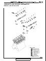
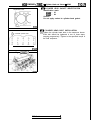
ENGINE
4G61, 4663, 4664
<1992>
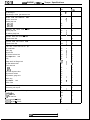
CONTENTS
BRACKET . . . . . . . . . . . . . . . . . . . . .,. . . . . . . . . . . . . . . . . . . . . . . . . . . . . . . . . . . . . . . 107
CAMSHAFTS AND ROCKER
ARMS - DOHC . . . . . . . . . . . . . . . . . . . . . . . . . . . . . . . . . . . . . . . . . . . . . . . . . . . . 71
CRANKSHAFT, FLYWHEEL AND
DRIVE PLATE . . . . . . . . . . . . . . . . . . . . . . . . . . . . . . . . . . . . . . . . . . . . . . . . . . . . . . . . 102
CYLINDER HEAD AND VALVES - SOHC . . . . . . . . 74
CYLINDER HEAD AND VALVES - DOHC . . . . . . . .
80
EXHAUST MANIFOLD AND
WATER PUMP . . . . . . . . . . . . . . . . . . . . . . . . . . . . . . . . . . . . . . . . . . . . . . . . . . . .
59
FRONT CASE, SILENT SHAFT AND
OIL PAN . . . . . . . . . . . . . . . . . . . . . . . . . . . . . . . . . . . . . . . . . . . . . . . . . . . . . . . . . . . . . . . .
85
FUEL AND EMISSION CONTROL PARTS . . . . 46
2
GENERAL INFORMATION . . . . . . . . . . . . . . . . . . . . . . . . . . . . . . . .
8
.
.
.
.
.
.
.
.
.
.
.
.
.
.
.
.
.
.
.
.
.
.
.
.
.
.
.
.
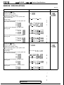
GENERAL SPECIFICATIONS
GENERATOR AND IGNITION
SYSTEM - SOHC ................................................
GENERATOR AND IGNITION
SYSTEM - DOHC ................................................
INTAKE MANIFOLD ............................................
PISTON AND CONNECTING ROD ....................
ROCKER ARMS AND CAMSHAFT- SOHC ....
SPECIAL TOOLS ....................................................
SEALANT ................................................................
SERVICE SPECIFICATIONS ................................
THROTTLE BODY ................................................
TIMING BELT - SOHC ........................................
TIMING BELT - DOHC . .......................................
TORQUE SPECIFICATIONS ................................
TURBOCHARGER ................................................
I
26
56
95
66
20
19
10
50
28
36
16
63
IIC-2
466 ENGINE <1992> - General Information
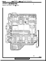
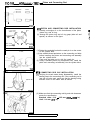
GENERAL INFQRMATION
I
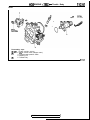
ENGINE SECTIONAL VIEW - SOHC
6EN0313
TSB Revision
.I
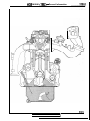
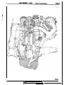
4G6 ENGINE <1992> - General Information
6EN0314
TSB Revision
I
IIC-4
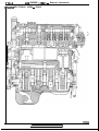
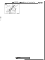
466 ENGINE <1992> - General Information
,NGlNE SECTIONAL VIEW - DOHC
TSB Revision
6EN0244
TSB Revision
\
IIC-6
466 ENGINE <1992> - General Information
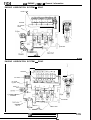
ENGINE LUBRICATION SYSTEM - SOHC
Rocker shaft
\
Camshaft
Oil pressure
switch
\
rankshaft
6LUOO39
ENGINE LUBRICATION SYSTEM - DOHC
Camshaft
Oil cooler
Oil cooler
by-pass valve
Silent shaft&I)
lressure switch
Crankshaft
Oil puml ’
I1 t- A/
‘Silent shaft
6LUOO55
TSB Revision
I
-
4G6 ENGINE <1992> - General Information
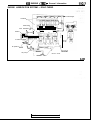
ENGINE LUBRICATION SYSTEM
DOHC-TURBO
- To turbocharger
Camshaft
ee
Silent shaft
From thermostat case
n
Oil filter
K
Oil cooler /
\
To water inlet41
pipe i I
EIe
+ I!
IJ
,
Key=
Oil pressure sw&h
Oil pump /
-7
(k,/ ‘Silent shaft Crankshaft
6LUOW6
1 TSB Revision
1
IIC-8
-4G6 ENGINE <1992> - General Specifications
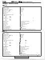
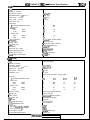
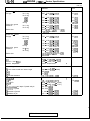
GENERAL SPECIFICATIONS
4G63 SOHC
Type
In-line OHV, SOHC
4
Compact type
1,997 (121.9)
85 (3.35)
88 (3.46)
8.5
Number of cylinders
Combustion chamber
Total displacement cm3 (cu. in.)
Cylinder bore
mm (in.)
Piston stroke
mm (in.)
Compression ratio
Valve timing
( ): camshaft identification mark
Intake valve
Open
BTDC
ABDC
Close
Exhaust valve
Open
BBDC
Close
ATDC
Lubrication system
Oil pump type
Cooling system
Water pump type
EGR system
Injector type and number
Injector identification mark
Throttle position sensor
Closed throttle position switch
(AR)
19"
57”
57”
1
19”
Pressure feed, full-flow filtration
Involute gear type
Water-cooled forced circulation
Centrifugal impeller type
Single type
Electromagnetic 4
N210H
Variable resistor type
Contact type, incorporated in idle speed control motor
4664 SOHC
1 In-line OHV, SOHC
Type
14
Number of cylinders
Combustion chamber
Total displacement
cm3 (cu. in .I
mm (in.)
Cylinder bore
mm (in.)
Piston stroke
Compression ratio
Valve timing
( ): camshaft identification mark
Intake valve
Open
BTDC
Close
ABDC
Exhaust valve
BBDC
Open
ATDC
Close
Lubrication system
Oil pump type
Cooling system
Water pump type
EGR system
Injector type and number
Injector identification mark
Throttle position sensor
Closed throttle position switch
Compact type
2,350 (143.4)
86.5 (3.35)
100 (3.46)
8.5
0)
(AR)
20”
64”
19”
57”
64”
57”
19”
20”
Pressure feed, full-flow filtration
Involute gear type
Water-cooled forced circulation
Centrifugal impeller type
Single type
Electromagnetic 4
N275H
Variable resistor type
Contact switch type, incorporated in idle speed control motor-TRUCK
Movable contact type, incorporated in throttle position sensor - EXPO
TSB Revision
4G6 ENGINE <1992> - General Specifications
1
TG9
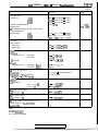
4661 DOHC
Type
In-line OHV, DOHC
4
Number of cylinders
Combustion chamber
cm3 (cu. in.)
Total displacement
Cylinder bore
mm (in.)
Piston stroke
mm (in,)
Compression ratio
Valve timing
( ): camshaft identification mark
Intake valve
Open
BTDC
Close
ABDC
Exhaust valve
Open
BBDC
Close
ATDC
Lubrjcatlon system
Oil pump type
Cooling system
Water pump type
EGR system
Injector type and number
Injector identification mark
Throttle position sensor
Closed throttle position switch
Pentroof type
1,595 (97.3)
82.3 (3.24)
75 (2.95)
,3.2
..
I33
(F)
16”
26”
38”
1$8”
L13
53”
17”
7”
f‘ressure feed, full-flow filtration
I nvolute gear type
1Water-cooled forced circulation
(Ientrifugal impeller type
:;ingle type
Eilectromagnetic 4
E3275H
Lrariable resistor type
CIontact type
4663 DOHC
Type
In-line OHV, DOHC
4
Pentroof type
1,997(121.9)
85 (3.35)
88 (3.46)
7.8 or 9.0
(Specs. varies according to engine model)
Number of cylinders
Combustion chamber
Total displacement
cm3 (cu. in.)
Cylinder bore
mm (in.)
Piston stroke
mm (in.)
Compression ratio
valve timing
( ): camshaft identification mark
Intake valve
Open
BTDC
Close
ABDC
Exhaust valve
BBDC
Open
ATDC
Close
Lubrication system
3il pump type
Cooling system
JVater pump type
EG R system
njector type and number
njector identification mark
Non-turbo
Turbo for GALANT/ECLIPSE M/T
Turbo for ECLIPSE A/T
Throttle position sensor
Closed throttle position switch
IA)
(B.C)
(D.C)
(EA
26”
46”
21”
43”
21”
51”
16”
48”
57”
15”
55”
9”
57”
55”
15”
3”
Pressure feed, full-flow filtration
Involute gear type
dater-cooled forced circulation
Centrifugal impeller type
Single type
!lectromagnetic 4
‘J240H
345OL
33901.
dariable resistor type
Contact type
piiEzGi
IIC-10
4G6 ENGINE <1992> - Service Specifications
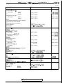
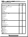
SERVICE SPECIFICATIONS
mm (in.)
Cylinder head - SOHC
Flatness of gasket surface
Grinding limit of gasket surface
* Total resurfacing depth of both cylinder head
and cylinder block.
Overall height
Oversize rework dimensions of valve guide hole
(both intake and exhaust)
0.05 (.002)
0.25 (.OlO)
0.50 (.020)
Oversize rework dimensions of intake valve
seat ring hole
0.30 f.012)
4G63
4G64
0.60 (024)
4663
4664
Oversize rework dimensions of exhaust valve
seat ring hole
0.30 l.012)
4663
4664
0.60 (.012)
4G63
4G64
Cylinder head - DOHC
Flatness of gasket surface
Grinding limit of gasket surface
* Total resurfacing depth of both cylinder head
and cylinder block.
Overall height,
Oversize rework dimensions of valve guide hole
(both intake and exhaust)
0.05 (.002)
0.25 (.OlO)
0.50 (020)
Oversize rework dimensions of intake valve
seat ring hole
0.30 i.012)
0.60 (024)
Oversize rework dimensions of exhaust valve
seat ring hole
0.30 l.012)
0.60 (.024)
Standard
Limit
0.05 (.0020)
0.2 (008)
*0.2 (008)
_I
89.9 - 90.1 (3.539 - 3.547)
I.
I-
13.05- 13.07 (.5138- .5146)
13.25-13.27(.5217-.5224)
13.50 - 13.52 (5315 - .5323)
i
44.30 - 44.33 (1.7441 - 1.7453)
47.30 -47.33 (3.8622 - 1.8634)
44.60 - 44.63 (1.7559 - 1.7571)
47.60 -47.63 (1.8740 - 1.8752)
4’
38.30
40.30
38.60
40.60
-
38.33 (1.5079 - 1.5091)
40.33 (1.5866 - 1.5878)
38.63 (1.5197 - 1.5209)
40.63 (1.5984 - 1.5996)
“J
~
0.2 (008)
“0.2 (008)
0.05 (0020)
131.9-132.1 (5.193-5.201)
12.05-12.07(.4744-.4752)
12.25 - 12.27 (4823 - .4831)
12.50 - 12.52 i.4921 - .4929)
)
35.30 - 35.33 (1.3898 - 1.3909)
35.60 - 35.63 (1.4016 - 1.4028)
c
-<
;
33.30 - 33.33 (1.3110 - 1.3122)
33.60 - 33.63 (1.3228 - 1.3240)
..
1
1 TSB Revision
466 ENGINE <1992> - Service Specification3
IWwl
mm (in.)
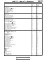
Standard
Camshaft - SOHC
Identification mark: D
Cam height
Identification mark: AR
Cam height
.,
;J’ _.
Intake
Exhaust
42.40 (1.6693)
42.40 (1.6693)
41’.90 (1.6496)
41.90 (1.6496)
Intake
Exhaust
44.53 (1.7531)
44.53 (1.7531)
44.03 (1.7335)
44.03 (1.7335)
NOTE:
The camshaft identification mark is stamped
on the rear end of the camshaft.
Fuel pump driving cam diameter
Journal diameter
Oil clearance
38 (1.50)
33.94 - 33.95 (1.3362 - 1.3366)
0.05 - 0.09 (.0020 - .0035)
Camshaft - DOHC
Intake
Identification mark: A,D
Cam height
dentification mark: B,C,E,F
Cam height
Exhaust
dentification mark: A
Cam height
dentification mark: C
Cam height
dentification mark E,F
Cam height
\lOTE:
The camshaft identification mark is stamped
In the rear end of the camshaft.
lournal diameter
Xl clearance
25.95 - 25.97 (1.0217 - 1.0224)
0.05 - 0.09 i.0020 - .0035)
locker arm - SOHC
.D.
sacker arm-to-shaft clearance
18.91 - 18.93 (.7445- .7453)
0.01 - 0.04 LOO04 - .0016)
-ash adjuster
.eak down test
Remarks: Diesel fuel at 15 - 20°C (59 - 68°F)
locker shaft - SOHC
I.D.
Iverall length
Limit
35.49 (1.3972)
34.99 (1.3776)
35.20 (1.3858)
34.70 (1.3661)
35.20 (1.3858)
34.70 (1.3661)
35.49 (1.3972)
34.99 (1.3776)
35.91 (1.3744)
34.41 (1.3547)
4 - 20 seconds/l mm (.04 in.)
18.89 - 18.90 (.7437 - .7441)
385.5(15.177)
372.5 (14.665)
Intake
Exhaust
1 TSB Revision
011 (.004)
IIC-12
466 ENGINE c1992> - Service Specifications
mm (in.)
Limit
Standard
Valve - SOHC
Overall length
Intake
Exhaust
Stem diameter
Face angle
Thickness of valve
head (margin)
Stem-to guide
clearance
Valve - DOHC
Overall length
Stem diameter
Face angle
Thickness of valve
head (margin)
Stem-to guide
clearance
4663
4664
4G63
4664
Intake
Exhaust
F
i
0.7 (02%)
1.5 (.059)
Intake
Exhaust
1.2 (047)
2.0 (.079)
Intake
Exhaust
0.02 - 0.06 (.OOO%- .0024)
0.05 - 0.09 (0020 - .0035)
Intake
Exhaust
Intake
Exhaust
109.5 (4.311)
109.7 (4.319)
6.57 - 6.58 (.2587 - .2591)
6.53 - 6.55 (2571 - .2579)
45” - 45”30’
Intake
Exhaust
1 .o (039)
1.5 (.059)
0.7 (02%)
1 .o l.039)
Intake
Exhaust
0.02 - 0.05 (.OOO%- .0020)
0.05 - 0.09 (0020 - .0035)
0.10 (004)
0.15 (006)
49.8 (1.961)
48.8 (1.921)
Valve spring - SOHC
Free height
~w$nstalled
N/mm (Ibs./in.)
Out-of-squareness
329/40.4 (73/I ,591)
2” or less
Valve spring - DOHC
Free height
k;;hnstalled
N/mm (IbsAn.)
Out-of-squareness
Valve guide- SOHC
Overall length
109.8(4.321)
106.6 (4.197)
108.7 (4.280)
105.2 (4.142)
7.96-7.98(.3134-.3142)
7.93-7.95 (.3122-.3130)
45”- 45”30’
0.10 (004)
0.15 (006)
_I
/
I
48.3 (1.902)
47.4 (1.866)
300/40 (66/l .57)
1.5” or less
Max. 4”
‘-;
47 (1.85)
52 (2.05)
8.00 - 8.02 (3150 - .3157)
13.06- 13.07 (.5142- .5146)
0.05(.002),0.25(.010),0.50(.020)oversize
Room temperature
Intake
Exhaust
I.D.
3.D.
Service size
Press-in temperature
1 TSB Revision
Max. 4”
4G6 ENGINE <1992> - Service Snebifications
mm (in.)
Standard
Valve guide - DOHC
Overall length
Limit
45.5 (1.791)
50.5 (1.988)
6.60 - 6.62 (.2598 - .2606)
12.06 - 12.07 (.4748 - .4752)
0.05 (.002), 0.25 (.OlO), 0.50 (.020) over size
Room temperature
I.D.
O.D.
Service size
Press-in temperature
Va Ive seat
Seat angle
Valve contact width
Sinkage
Service size
43”30’ - 44”
0.9 - 1.3 (.035 - .051)
0.2 (.OO%)
0.3 (.012), 0.6 (.024) over size
Silent shaft
Journal diameter
41.96 - 41.98 (1.6520 - 1.6528)
40.95 - 40.97 (1.6122 - 1.6130)
18.47 - 18.48 (.7272 - 0.7276)
40.95 - 40.97 (1.6122 - 1.6130)
0.03 - 0.06 LOO1 2 - .0024)
0.05-0.09 (.0020-.0036)
0.02 - 0.05 (.OOO% - .0020)
0.05 - 0.09 (.0020- .0036)
3il clearance
‘iston - SOHC
I.D.
4663
4G64
Won to cylinder clearance
service size
84.97 - 85.00 (3.3453 - 3.3465)
86.47 - 86.50 (3.404 - 3.4055)
0.02-0.04(.0008-.0016)
0.25 LOlO), 0.50 (.020), 0.75 (.030),
1 .OO f.039) over size
Won - DOHC
I.D.
4G61
4663 - Non-turbo
4G63 -Turbo
‘iston to cylinder clearance
Non-turbo
Turbo
;ervice size
1 TSB Revision
82.27 - 82.30 (3.2390 - 3.2401)
84.97 - 85.00 (3.3453 - 3.3465)
84.96 - 84.99 (3.3449 - 3.3461)
0.02 - 0.04 (.OOO% - .0016)
0.03 -0.05 (.0012 - .0020)
0.25 (.OlO), 0.50 (.020), 0.75 (.030).
1 .OO (.039) over size
1
466 ENGINE <1992>
- Service Specifications
mm (in.)
Piston ring - SOHC
End gap
Ring-to-ring groove
clearance
Standard
Limit
No. 1 ring
No. 2 ring
4663
4664
Oil ring
0.25 - 0.40 LOO98 - .0157)
0.8 (031)
0.20 - 0.35 LOO79 - .0138)
0.20 - 0.40 LOO79 - .0157)
0.20 - 0.70 LOO79 - .0276)
0.8 (.031)
0.8 (.031)
1 .o (.039)
No. 1 ring
No. 2 ring
0.03 - 0.07 LOOI 2 - .0028)
0.02 - 0.06 (.OOO% - .0024)
0.25 (.OlO), 0.50 (.020), 0.75 (.030),
1 .OO (.039) over size
0.1 (.004)
0.1 (004)
No. 1 ring
No. 2 ring
4G61
4663
Oil ring
0.25 - 0.40 LOO98 - .0157)
0.8 (031)
0.35 - 0.50 (013% - .0197)
0.45 - 0.60 f.0177 - .0236)
0.20 - 0.70 LOO79 - .0276)
0.8 (.031)
0.8 (031)
1 .o f.039)
0.03 - 0.07 (.0012 - .0028)
0.03 - 0.07 LOO1 2 - .0028)
0.25 LOlO), 0.50 (.020), 0.75 (.030),
1 .OO (.039) over size
0.1 (004)
0.1 (004)
Service size
Piston ring - DOHC
End gap
Ring-to-ring groove
clearance
No. 1 ring
No. 2 ring
Service size
Piston pin
3.D.
Press-in load N (Ibs.)
press-in temperature
21 .OO - 21 .Ol (826% - .8272)
7,500 - 17,500 (1,653 - 3,858)
Room temperature
Connecting rod
3ig end center-to-small end center length
3end
rwist
3ig end side clearance
149.9 - 150.0 (5.902 - 5.906)
0.05 (002)
0.1 (004)
O.lO-0.25(.0039-.0098)
:
0.4 (016)
:!
Crankshaft
fnd play
Journal O.D.
‘in O.D.
ht-of-roundness and taper of journal and pin
kcentricity of journal
Iii clearance of journal
II clearance of pin
TSB Revision
0.05-0.18 (.0020- .0071)
56.98 - 57.00 (2.2433 - 2.2441)
44.98 - 45.00 (1.7709 - 1.7717)
Max. 0.01 (.0004)
Max. 0.02 (.OOO%)
0 . 0 20.05
- (.OOO% - .0020)
0.02 0.05
- (.OOO% - .0020)
0.25 (.0098)
0.1 (004)
0.1 (004)
466 ENGINE t1992> - Service Sbecifications
.’ mm (ir
_’
Standard
Cylinder block
Cylinder I.D.
4G61
4663
4664
82.30 - 82.33 (3.2402 - 3.2413)
85.00 - 85.03 (3.3465 - 3.3476)
86.50 - 86.53 (3.4055 - 3.4067)
0.05 (0020)
Flatness of gasket surface
Grinding limit
* Total resurfacing depth of both cylinder head
and cylinder block.
Overall height
4G61
4663
4G64
274.9 - 275.1 (10.823 - 10.831)
283.9-284.1 (11.177-11.185)
289.9-290.1 (11.413-11.421)
Oil pump
Side clearance
Drive gear
Driven gear
0.08 - 0.14 (0031 - .0055)
0.06 - 0.12 (0024 - .0047)
3rive belt
Ieflection
V-ribbed type belt
New belt
Used belt
V type belt
-ension
V-ribbed type belt
New belt
Used belt
7.5 - 9.0 (.30 - .35)
8.0 (32)
7.0 - 10.0 (28 - .39)
N (Ibs.)
N (Ibs.)
Xl cooler by-pass valve
Iimension (L)
ly-pass hole closing temperature
37 - 103°C (207 - 217°F) or more)
500 - 700 (11 O’- 154)
400 (88)
34.5 (1.358) - normal temperature
40 (1.57) or more
ejector
Ioil resistance
Non -turbo Q
Turbo R
13 - 16 at 20°C (68°F)
2 - 3 at 20°C (68°F)
Jle speed control motor
:oil resistance CR
5 - 35 at 20°C (68°F)
Ale air control motor
:oil resistance Cn
28 - 33 at 20°C (68°F)
Ale speed control motor position sensor
SOHC engine for GALANTITRUCK
lesistance klR
4-6
NOTE
0.D.; OuteL piameter
I.D.: Inner Diameter
U.S.: Undersize Diameter
TSB Revision
Limit
0.1 (004)”
*0.2 (.008)
IIC-16
4G6 ENGINE <1992> - Torque Specifications
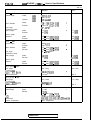
TORQUE SPECIFICATIONS
Generator and ignition system - SOHC
Cooling fan bolt
Water pump pulley bolt - Engine without cooling fan
Water pump
pulley bolt - Engine with cooling fan
Generator brace bolt
Generator mounting bolt
Generator pivot nut
Crankshaft pulley bolt
Spark plug
Distributor nut
Nm
ft.1b.s.
11
8
7
8
10
17
17
18
18
8
IO
13
Ignition coil bolt
Ignition power transistor nut
9
11
14
24
23
25
25
11
14
18
Generator and ignition system - DOHC
W a t e rpump
pulley bolt
Generator brace bolt
Generator mounting bolt
Generator pivot nut
Crankshaft pulley bolt
Center cover bolt
Spark plug
Ignition coil bolt
Ignition power transistor bolt
Crankshaft position sensor nut
9
14
24
23
25
3
25
24
11
1
Timing belt - SOHC
Tensioner bolt
Tensioner spacer
Oil pumpsprocket
nut
Crankshaft sprocket bolt
Tensioner “B” bolt
Silent shaft sprocket bolt, right
Engine supports bracket bolt, left
Camshaft sprocket bolt
49
49
55
120
19
46
36
90
riming belt- D O H C
Tensioner pulley bolt
Tensioner arm bolt
Idler pulley bolt
3il pump sprocket nut
Crankshaft sprocket bolt
Tensioner “B” bolt
Silent shaft sprocket bolt, right
qocker cover bolt
3amshaft sprocket bolt
Engine support bracket, left
49
22
38
55
120
19
46
3
90
36
.;
f
9.i
:
:
7
IO
17
17
18
2
18
17
8
14
35
35
40
87
14
33
26
65
:
1 TSB Revision
j
“.
1
35
16
27
40
87
14
33
22
65
26
IIC-17
4G6 ENGINE <1992> - Toraue SDecifications
Nm
ftlbs.
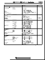
Fuel and emission parts
EGR valve bolt
Throttle body stay nut - DOHC
Throttle body bolt - SOHC
Throttle body bolt - DOHC
Fuel pressure
regulator
bolt
Fuel rail bolt
19
19
12
19
9
12
14
14
9
14
7
9
Throttle body
Throttle position sensor bolt
Idle speed control motor bolt
Idle air control motor bolt
2
3.5
3.5
1.4
2.5
2.5
Intake manifold plenum bolt and nut
Intake manifold plenum stay bolt
Water outlet fitting bolt
Engine coolant temperature gauge unit
Engine coolant temperature sensor
Thermostat case nut
18
36
22
28
18
18
19
11
30
18
13
26
16
20
13
13
14
8
22
13
Exhaust manifold and water pump
Oil level
guide bolt
gauge
60
43
Heat protector bolt
GALANT AND EXPO
TRUCK
Exhaust manifold nut - SOHC
Exhaust manifold nut - DOHC
Engine hanger bolt - DOHC
Air outlet fitting bolt
Turbocharger bolt and nut
Exhaust fitting bolt
Water inlet pipe bolt
Water pump bolt
14
30
18
28
14
19
60
60
14
24
Water pipe “A“ and “B” eye bolt
Water pipe “A“ bolt
Water pipe “B” flare nut
43
11
45
10
22
13
20
10
14
43
43
10
17
31
8
33
Water pipe bolt
M8
M6
Oil return pipe bolt
14
11
9
10
8
7
Oil pipe
Cylinder head side
Turbocharger side
17
31
12
22
Intake manifold
Intake manifold bolt and nut
Intake manifold nut - DOHC
Intake manifold stay bolt - SOHC
Intake manifold stay bolt - DOHC
1 TSB Revision
I
IIC-18
466 ENGINE <1992> - Torque Specifications
ftlbs.
Nm
r
Turbocharger
Turbocharger waste gate actuator bolt
12
Rocker arms and camshaft- SOHC
Rocker cover bolt
6
Bearing cap bolt
M8x25
M8x65
24
20
Camshafts and rocker arms - DOHC
Bearing cap bolt
Oil delivery body bolt
20
11
Cylinder head and valves - SOHC
Cylinder head bolt
95
Cylinder head and valves- DOHC
Cylinder head bolt
110
Front case, silent shaft and oil pan
Oil cooler bolt
Drain plug
Oil pan bolt
Oil screen bolt and nut
Oil pump
sprocket
bolt
Plug
Silent shaft, left flange bolt
Oil filter bracket bolt
Front case bolt
9
4
’
!.
17
14
?
(’
;
14
8
69
:/
;(
43
40
7
19
55
24
:
:
:
-’
;
37
19
t
!
M8
Ml0
Oil cooler by-pass valve
Oil pressure switch
Oil pressure gauge unit
Relief plug
Oil pump
cover
bolt
Check valve
24
31
55
10
55
45
17
33
-.~
Piston and connecting rod
Connecting rod cap nut
52
.?&
::
!
80
31
29
5
14
40
17
27
14
17
22
40
7
40
33
12
24
38
Crankshaft, flywheel and drive plate
135
135
11
53
68
+wheel bolt
Irive plate bolt
3il seal case bolt
3earing cap bolt - SOHC
3earing cap bolt - DOHC
TSB Revision
98
98
8
38
49
1 IC-19
4G6 ENGINE <1992> - Torque Specifications / Sealant
Bracket
Left and right engine support bracket bolt
Roll stopper bracket bolt, front
Roll stopper bracket bolt, rear
Engine support bracket bolt, front
Exhaust pipe support bracket bolt
Nm
ft.lbs.
45
65
120
60
36
33
47
87
43
26
SEALANT
Rocker cover
Semi-circular packing
Oil pan gasket
Engine coolant temperature gauge unit
Engine coolant temperature sensor
Oil pressure switch
Oil pressure gauge unit
Specified sealant
Quantity
3M ATD Part No. 8660 or equivalent
3M ATD Part No. 8660 or equivalent
MITSUBISHI GENUINE PART
MD970389 or equivalent
3M ATD Part No. 8660 or equivalent
3M Nut Locking Part No. 4171
or equivalent
3M ATD Part No. 8660 or equivalent
3M ATD Part No. 8660 or equivalent
As required
As required
As required
1 TSB Revision
I
As required
As required
As required
As required
11 c-20
466 ENGINE <1992> - Special Tools
SPECIAL TOOLS
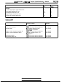
Tool
Number and
tool name
Supersession
Application
MB990767
End yoke holder
Use with
MD9987 19
M 8990767-01
Use with MIT308239
Holding camshaft spr&ket when loosening
or torquing bolt.
For SOHC engine only
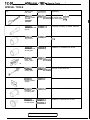
MD998051-01
MD998051
Cylinder head bolt
wrench
Loosening or torquing of cylinder head bolt
M D998162
Plug wrench
MD9981 62-01
Removal and installation of front case cap
plug
M D998285
Crankshaft front
oil seal guide
M D998285-0 1
Installation of crankshaft front oil seal
MD998371
Silent shaft
bearing puller
MD998371-01
Use with MIT304204
Removal of silent shaft rear
M D998372
Silent shaft
bearing puller
M D998372-01
Use with MIT304204
Removal of silent shaft rear
MD998374
Bearing installer
stopper
M D998374-0 1
Removal and installation of rear bearing
MD998375
Crankshaft front
oil seal installer
MD998375-01
nstallation of crankshaft front oil seal
MD998376
Crankshaft rear
oil seal installer
MD998376-01
Use with
MB990938-01
nstallation of crankshaft rear oil seal
QQ
c
1 TSB Revision
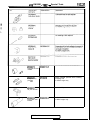
4G6 ENGINE <1992> - Special Tools
MD998713
Camshaft oil seal
installer
MD998713-01
MD99871 9
Pulley holding
pins (2)
M IT308239
Removal of oil pan
MD998727
Oil pan remover
MD998729
Valve stem seal
installer
Holding camshaft sprocket when loosening
or torquing bolt
For SOHC engine only
MD998729-01
TSB Revision
Installation of valve stem seal
For SOHC engine only
IIC-22
4G6 ENGINE <1992> - Special Tools
Holding silent shaft sprocket
M D998779
Sprocket stopper
MD998780
Piston pin
setting tool
M IT2 16941
MD998781
Flywheel stopper
TSB Revision
Removal and installation of piston pin
Holding flywheel
466 ENGINE <1992> - Generator and Ignition System - SOHC
1 IC-23
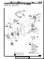
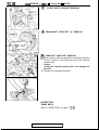
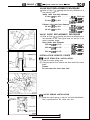
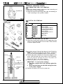
GENERATOR AND IGNITION SYSTEM - SOHC
REMOVAL AND INSTALLATION
25 Nm
14 Nm
lOft.lbs.
-1
0Q
I
23 Nm
!!!?a R W D
17 ft.lbs.
I
14 Nm
10 ftlbs.
I
24 Nm
17 ftlbs.
4
5
I
9 Nm**
7 ftlbs.
11 Nm***
8 ft.lbs.
Removal steps
*B4 1. Drive belt
2. Cooling fan***
3. Fan clutch***
4. Water pump pulley”
5. Water pump pulley
6. Generator brace
7. Generator
8. Crankshaft pulley
9. Spark plug cable
10. Spark plug
11. High tension cable
*A4 12. Distributor
NOTE
* : Engine with power steering
** : Engine with cooling fan
***: Engine without cooling fan
13. Ignition coil
14. Ignition power transistor
6EN0631
TSB Revision
1
1 IC-24
466 E N G I N E <1992> - Generator and Ignition System - SOHC
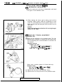
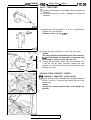
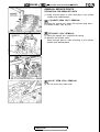
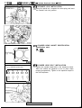
INSTALLATION SERVICE ,POINTS
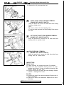
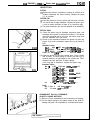
r)A4 DISTRIBUTOR INSTALLATION
(1) Align the marks put at the time of disassembly, and install
the gear to the distributor shaft.
(2) When aligning the driven gear’s mating mark and the
housing’s mating marks, make the combination so that
notch “A” at the shaft end is at the position shown in the
figure, and then align the spring pin holes and drive in a new
spring pin.
Caution
Drive in the spring pin so that the slit is at a right angle
relative to the shaft.
1ELOOlf
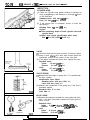
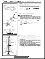
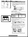
*64 DRIVE BELT TENSION ADJUSTMENT
ADJUSTER TYPE
(1) Adjust the belt deflection to the standard value. Turn the
adjusting bolt clockwise to increase the belt tension and
turn the adjusting bolt counterclockwise to decrease the
belt tension.
Standard value: ’
V-ribbed type belt
New belt 7.5 - 9.0 mm (30 - .35 in.)
Used belt 8.0 mm (32 in.)
V-type belt 7.0 - 10.0 mm (28 - .39 in.)
When using a tension gauge for V-ribbed belt only.
Standard value:
New belt 500 - 700 N (110 - 154 Ibs.)
Used belt 400 N (88 Ibs.)
(2) Tighten the lock bolt to the specified torque.
(3) Tighten the nut for the pivot bolt to the specified torque.
TSB Revision
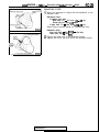
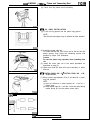
4G6 ENGINE <1992> - Generator and Ignition Svstem - SOHC
Water
pulley
Crankshaft pulley
6EN0593
/‘, Water pump pulley
1 ICE-25
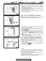
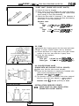
BRACE BOLT TYPE
(1) Move the generator to adjust the belt deflection to the
standard value.
Standard value:
V-ribbed type belt
New belt 7.5 - 9.0 mm (.30 - .35 in.)
Used belt 8.0 mm (.32 in.)
V-type belt 7.0 - 10.0 mm (.28 - .39 in.)
When using a tension gauge for V-ribbed belt only.
Standard value:
New belt 500 - 700 N (110 - 154 Ibs.)
Used belt 400 N (88 Ibs.)
(2) Tighten the brace bolt to the specified torque.
(3) Tighten the nut for the pivot bolt to the specified torque.
Altern
pulley
6EN059E
TSB Revision
11 C-26
4G6 ENGINE <1992>
- Generator and Ignition System - DOHC
GENERATOR AND IGNITION SYSTEM - DOHC
REMOVAL AND INSTALLATION
18 ft.lbs.
19 Nm
14 ftlbs.
5
23 Nm
I
14 Nm
10 ft.lbs.
24 Nm
17 ftlbs.
I
11
11 Nm
8 ft.lbs.
24 Nm
17 ftlbs.
Removal steps
eB4 1. Drive belt
2. Water pump pulley
3. Water pump pulley
(For driving power steering pump)
4. Generator brace
5. Generator
6. Crankshaft pulley
7. Center cover
8.-Spark plug cable
9. Spark plug
10. Ignition coil
11. Ignition power transistor
#A4 12. Crankshaft position sensor
13. O-ring
TSB Revision
I
466 ENGINE <1992> - Generator and Ignition System - DOHC
IIC-27
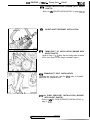
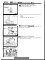
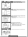
INSTALLATION SERVICE POINTS
#A4
CRANKSHAFT POSITION INSTALLATION
(1) Turn the crankshaft so that the No. 1 cylinder is at top dead
center.
(2) Align the punch mark on the crankshaft position sensor
housing with the notch in the plate.
(3) Install the crankshaft position sensor on the cylinder head.
eB4 DRIVE BELT TENSION ADJUSTMENT
Refer to “I)B4 DRIVE BELT TENSION ADJUSTMENT” on
page 11 C-24.
1 TSB Revision
I
II
11 C-28
4G6 ENGINE <1992> - Timing Belt - SOHC
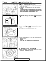
TIMING BELT - SOHC
REMOVAL AND INSTALLATION
18
EE
Nm
1” . . . . .
40 ft.lbs.
i”
F 87
---ft.lbs.
--~~~
Removal steps
1. Timing belt front upper cover
2. Timing belt front lower cover
(IAI) eH4 3. Timing belt
#Gg 4. Tensioner spring
*Gg 5. Tensioner
QBg eF4 6. Oil pump sprocket
81: $E4 7. Crankshaft bolt
8. Crankshaft sprocket
9. Flange
10. Tensioner “B”
c$ErJ eD4 11. Timing belt “B”
(IFI) #C4 12. Silent shaft sprocket, right
#B4 13. Spacer
14. Crankshaft sprocket “B”
($0
15. Engine support bracket, left
(IHI) *A4 16. Camshaft sprocket bolt
17. Camshaft sprocket
18. Timing belt rear cover
6EN0633
TSB Revision
4G6 ENGINE <1992> - Timing Belt - S O H C
IIC-29
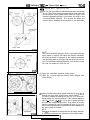
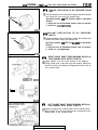
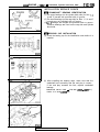
REMOVAL SERVICE POINTS
QAo
TIMING BELT REMOVAL
(1) Mark the belt running direction for reference in reinstallation.
NOTE
(1) Water or oil on the belt shortens its life drastically, so
the removed timing belt, sprocket, and tensioner must
be free from oil and water. These parts should not be
washed. Replace parts if seriously contaminated.
(2) If there is oil or water on each part, check the front case
oil seals, camshaft oil seal and water pump for leaks.
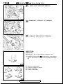
QBQ OIL PUMP SPROCKET REMOVAL
(1) Remove the plug on the left side of the cylinder block.
(2) Insert a Phillips screwdriver [shank diameter 8 mm (31 in.)]
to block the left silent shaft.
(3) Remove the nut.
(4) Remove the oil pump sprocket.
6EN0563
6EN056~
@@ CRANKSHAFT BOLT REMOVAL
(1) Using the special tool, hold the drive plate or flywheel.
(2) Remove the crankshaft bolt.
@I) CRANKSHAFT SPROCKET REMOVAL
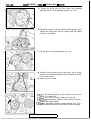
QEo
TIMING BELT “B” REMOVAL
(1) Make a mark on the back of the timing belt indicating the
direction of rotation so that it may be reassembled in the
same direction if it is to be reused.
NOTE
(1) Water or oil on the belt shortens its life drastically, so
the removed timing belt, sprocket, and tensioner must
be free from oil and water. These parts should not be
washed. Replace parts if seriously contaminated.
(2) If there is oil or water on each part, check the front case
oil seals, camshaft oil seal and water pump for leaks.
TSB Revision
4G6 ENGINE <1992> - Timing Belt - SOHC
(IF0
SILENT SHAFT SPROCKET REMOVAL
QGt)
CRANKSHAFT SPROCKET “B” REMOVAL
aHo
CAMSHAFT SPROCKET BOLT REMOVAL
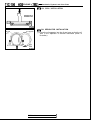
INSPECTION
TIMING BELT
Replace belt if any of the following conditions exist.
(1) Hardening of back rubber - the back side is glossy without
resilience and leaves no indent when pressed with fingernail.
\
00 B
000
&
8EN006Z
(2)
(3)
(4)
(5)
Peeling
Cracks
Cracks
1 EN0249
1 TSB Revision
Cracks
Cracks
Cracks
Cracks
on rubber back.
or peeling of canvas.
on rib root.
on belt sides.
4G6 ENGINE <1992> - Timing Belt - SOHC
1 IC-31
(6) Abnormal wear of belt sides. The sides are normal if they
are sharp as if cut by a knife.
Roundededge
Abnormal wear
(Fluffy strand)
8EN006;
(7) Abnormal wear on teeth.
(8) Missing tooth.
Rubber exposed
Tooth missing
and canvas fiber
8EN006t
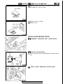
INSTALLATION SERVICE POINTS
I)A4 CAMSHAFT SPROCKET BOLT INSTALLATION
I)B4 SPACER INSTALLATION
Spacer
53
Oil seal
I
A%&
7/
/y/7/,
f
\
Chamfer
Silkt
shaft
b
(1) Install the spacer with the chamfered end toward the oil
seal.
6EN061 E
I)c4 SILENT SHAFT SPROCKET INSTALLATION
1 TSB Revision
I
11 C-32
466 ENGINE <1992> - Timing Belt - S O H C
+D4
TIMING BELT “B” ‘INSTALLATION
(1) Align timing marks on the crankshaft sprocket “B” and
silent shaft sprocket with the marks on the front case
respectively.
(2) Install the timing belt “B” on the crankshaft sprocket “B”
and silent shaft sprocket. There should be no slack on the
tension side.
(3) Make sure that the relationship between the tensioner
pulley center and the bolt center is as shown in the
illustration.
Center of yx \ tensioner m P,...*-- -L L-Or.
k
W
/
6EN057’
(4) Move the tensioner “B” in the direction of arrow while
lifting with a finger to give a sufficient tension to the tension
side of timing belt. In this condition, tighten the bolt to
secure tensioner “B”. When the bolt is tightened, use care
to prevent shaft from turning together. If the shaft is turned
together, the belt will be over-tensioned.
(5) Check to ensure that the timing marks on the sprockets and
front case are in alignment.
(6) Press with index finger the center of span on the tension
side of timing belt “B”. The belt must deflect 5 - 7 mm (.20
- .28 in.).
+E4
CRANKSHAFT BOLT INSTALLATION
(1) Using the special tool, hold the drive plate or flywheel.
(2) Install the crankshaft bolt.
TSB Revision
1 IC-33
4G6 ENGINE <1992> - Timing Belt - SOHC
I)F4 OIL PUMP SPROCKET INSTALLATION
(1) Insert a Phillips screwdriver [shank diameter 8 mm (31 in.)]
through the plug hole on the left side of the cylinder block to
block the left silent shaft.
(2) Install the oil pump sprocket.
(3) Apply an appropriate amount of engine oil to the bearing
surface of the nut.
(4) Tighten the nut to the specified torque.
Screwdriver
6EN0564
I)G4
TENSIONER INSTALLATION
(1) Hook the tensioner spring ends to the water pump body
projection and tensioner bracket.
(2) Move the tensioner fully toward the water pump and
tighten the bolt and tensioner spacer.
Tensloner
-
6EN0555
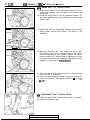
I)H4 TIMING BELT INSTALLATION
(1) Align the timing marks on camshaft sprocket and crankshaft sprocket with their mating marks.
(2) Align the timing mark on the oil pump sprocket with its
mating mark.
Timing mark
Timing mark
for on-vehicle
service only
/
I/
ilange
-/
Timing mark
Cal nshaft sprocket
Crankshaft
6EN0475
1 TSB Revision
IIC-34
4G6 ENGINE <1992> - Timing Belt - SOHC
6EN0563
6EN0564
(3) Remove the plug on the cylinder block and insert a Phillips
screwdriver [shank diameter 8 mm (.31 in.) ] through the
hole (Engine with silent shafts).
If it can be inserted as deep as 60 mm (2.4 in.) or more, the
timing marks are correctly aligned. If the inserted depth is
only 20 - 25 mm (.8 - 1.0 in.), turn the oil pump sprocket
one turn and realign the timing marks. Then check to
ensure that the screwdriver can be inserted 60 mm (2.4 in.)
or more. Keep the screwdriver inserted until installation of
the timing belt is finished.
(4) Install the timing belt on the crankshaft sprocket, oil pump
sprocket and camshaft sprocket in that order. There should
be no slack on the tension side.
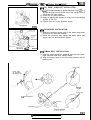
(5) Loosen the tensioner mounting bolt and tensioner spacer.
Tensioner spacer
Timing mark
(6) Turn the crankshaft clockwise by two teeth of camshaft
sprocket (or crankshaft sprocket).
(7) Apply force to the tensioner in the direction shown by arrow
@I to make the belt engage completely with each sprocket.
1 TSB Revision
4G6 ENGINE <1992> - Timinn Belt - SOHC
1
tc-35
(8) Tighten the tensioner attaching bolt, then tighten the
tensioner spacer.
Caution
If the tensioner spacer is tightened first, the tensioner
turns as the tensioner spacer is tightened, resulting in
an excessive belt tension.
i
-
(9) Hold the center of the tension side span of the timing belt
(between the camshaft and oil pump sprockets) between
your thumb and index finger as shown. Then, make sure
that the clearance between the belt back surface and cover
is standard value.
Standard value: 14 mm (.55 in.)
TSB Revision
WC-36
4G6 ENGINE <1992> - Timing Belt - DOHC
TIMING BELT - DOHC
REMOVAL AND INSTALLATION
3Nm
2.2 ft.lbs. -fl
*?
A
24
I
'25
e
1
87ft.lbs.
NO TE
* : Engine without silent shafts
** Engine with silent shafts
TSB Revision
Removal steps
1. Timing belt front upper cover
2. Timing belt front lower cover
(IAIJ eK4 3. Timing belt
eJ4 4. Tensioner pulley
5. Tensioner arm
#I4 6. Auto tensioner
7. Idler pulley
(~Brj +H4 8. Oil pump sprocket
$I$ eG4 9. Crankshaft sprocket bolt
10. Crankshaft sprocket
11. Flange
12. Spacer*
13. Tensioner “B”**
OEo eF4 14. Timing belt “B”“”
(IFO eE4 15. Silent shaft sprocket**
+D4 16. Spacer**
17. Crankshaft sprocket “B”**
4GO
I)C4 18. Rocker cover
#B4 19. Semi-circular packing
(IHO *A4 20. Camshaft sprocket bolt
21. Camshaft sprocket
22. Engine support bracket
23. Timing belt rear right cover
24. Timing belt rear left upper cover
25. Timing belt rear left lower cover
I
466 ENGINE <1992> - Timing ,Felt - DOHC
IIC-37
REMOVAL SERVICE POINTS
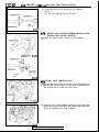
OAi) TIMING BELT REMOVAL
(1) Make a mark on the back of the timing belt indicating the
direction of rotation so that it may be reassembled in the
same direction if it is to be reused.
NOTE
(1) Water or oil on the belt shortens its life drastically, so
the removed timing belt, sprocket, and tensioner must
be free from oil and water. These parts should not be
washed. Replace parts if seriously contaminated.
(2) If there is oil or water on each part, check the front case
oil seals, camshaft oil seal and water pump for leaks.
OBo OIL PUMP SPROCKET REMOVAL (ENGINE WITH
SILENT SHAFTS)
Refer to “@o OIL PUMP SPROCKET REMOVAL” on page
11 c-29.
of@ CRANKSHAFT BOLT REMOVAL
(1) Using the special tool, hold the drive plate or flywheel.
(2) Remove the crankshaft bolt.
ODo CRANKSHAFT SPROCKET REMOVAL
~EI)
&hdd~l~ELT “B” REMOVAL (ENGINE WITH SILENT
Refer to “OEO TIMING BELT “B” REMOVAL” on page
11 c-29.
TSB Revision
I
1 IC-38
4G6 ENGINE <1992> - Timing Belt - DOHC
OF0
QGo
SILENT SHAFT SPROCKET REMOVAL
CRANKSHAFT SPROCKET “B” REMOVAL
(IHO
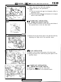
CAMSHAFT SPROCKET REMOVAL
(1) Using a wrench, hold the camshaft at its hexagon (between
the No. 2 and No. 3 journals) and remove the camshaft
sprocket bolt.
Caution
Locking the camshaft sprocket with a tool damages the
sprocket.
(2) Remove the camshaft sprockets.
INSPECTION
TIMING BELTS
Refer to “INSPECTION” on page 1 IC-29.
TSB Revision
4G6 ENGINE <1992> - Timina Belt - D O H C
IX-39
AUTO TENSIONER
(1) Check the auto tensioner for possible leaks and replace as
necessary.
(2) Check the rod end for wear or damage and replace as
necessary.
(3) Measure the rod protrusion. If it is out of specification,
replace the auto tensioner.
Standard value: 12 mm (.47 in.)
12mm
( 47 in.)
a
0
1
0
0
‘il;
6EN0161
I
(4) Clamp the auto tensioner in a vise with soft jaws.
Caution
The plug protrudes at the bottom of the auto tensioner.
Insert a plain washer as illustrated to prevent the plug
from being in direct contact with the vise.
(5) Turning the vise handle, push in the auto tensioner rod.
If the rod can be easily retracted, replace the auto
tensioner. You should feel a fair amount of resistance when
pushing the rod in.
Brass or
aluminum laws
aluminum jaws
'6EN0404
INSTALLATION SERVICE POINTS
#A4
CAMSHAFT SPROCKET INSTALLATION
(1) Using a wrench, hold the camshaft at its hexagon (between
the No. 2 and No. 3 journals) and tighten the bolt to the
specification.
Caution
Locking the camshaft sprocket with a tool damages the
sprocket.
TSB Revision
11 c-40
4G6 ENGINE <1992> - Timing Belt - DOHC
I)B4
SEALANT APPLICATION ON SEMI-CIRCULAR
PACKING
Specified sealant: 3M ATD Part No. 8660 or equivalent
Apply sealant
‘:
::.:..
. .
-.-.*...a. . . . . . . . . . . . . . . . ....::::::::.:.:.:.:.:.:..
..*.-.-.*,*.d
1
DEN0052
3EN0044
ec4
SEALANT APPLICATION ON ROCKER COVER
Apply sealant to the areas indicated in the illustration.
Specified sealant: 3M ATD Part No. 8660 or equivalent
Apply sealant
I
IOmm
f.39 in.)
Apply sealant
BEN0396
1 TSB Revision
4G6 ENGINE <1992> - Timing Belt - D O H C
1
x-47
I)04 SPACER INSTALLATION (ENGINE WITH SILENT
SHAFTS)
Refer to “eB4 SPACER INSTALLATION” on page 11 C-31.
r)E$
SILENT SHAFT SPROCKET INSTALLATION
I)F+
TIMING BELT “B” INSTALLATION (ENGINE WITH
SILENT SHAFTS)
Refer to Page 11 C-32. Note that the timing mark locations
differ from those on the single camshaft engine.
I)G+
CRANKSHAFT BOLT INSTALLATION
(1) Using the special tool, hold the drive plate or flywheel.
(2) Install the crankshaft bolt.
#H4 OIL PUMP SPROCKET INSTALLATION (ENGINE
WITH SILENT SHAFTS)
Refer to “I)F4 OIL PUMP SPROCKET INSTALLATION” on
page 11 C-33.
1 TSB Revision
11 C-42
466 ENGINE <1992> - Timing Belt - DOHC
1)14 AUTO TENSIONER INSTALLATION
(1) If the auto tensioner rod is in its fully extended position,
reset it as follows.
(2) Clamp the auto-tensioner in the vise with soft jaws.
Caution
The plug protrudes at the bottom of the auto tensioner.
Insert a plain washer as illustrated to prevent the plug
from being in direct contact with the vise.
(3) Push in the rod little by little with the vise until the set hole
@ in the rod is aligned with the hole @I in the cylinder.
6EN015,
Wir>e
4
(4) Insert a wire [I .4 mm (055 in.) in diameter] into the set
holes.
(5) Unclamp the auto tensioner from the vise.
y-A
\
J040E
(6) Install the auto tensioner to front case and tighten to the
specified torque.
Caution
Leave the wire installed in the auto tensioner.
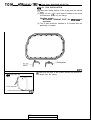
I)J4 TENSIONER PULLEY INSTALLATION
(1) Install the tensioner pulley in such direction that its two
small holes are arranged vertically.
1 TSB Revision
466 ENGINE <1992> - Timina Belt - D O H C
r)K4
Camshaft sprocket
1 IC-43
TIMING BELT INSTALLATION
(I) Turn the two sprockets so that their dowel pins are located
on top. Then, align the timing marks facing each other with
the top surface of the cylinder head. When you let go of the
exhaust camshaft sprocket, it will rotate one tooth in the
counterclockwise direction. This should be taken into
account when installing the timing belt on the sprockets.
Timing marks
6EN0284
NOTE
The same camshaft sprocket which is provided with two
timing marks is used for the intake and exhaust camshafts.
When the sprocket is mounted on the exhaust camshaft,
use the timing mark on the right with the dowel pin hole on
top. For the intake camshaft sprocket, use the one on the
left with the dowel pin hole on top.
6ENOll E
(2) Align the crankshaft sprocket timing marks.
(3) Align the oil pump sprocket timing marks (Engine with
silent shafts).
1
Engine with silent shafts
Screwdriver
6EN0564
(4) Insert a Phillips screwdriver [shank diameter 8 mm (.31 in.)]
through the plug hole (Engine with silent shafts).
If it can be inserted as deep as 60 mm (2.4 in.) or more, the
timing marks are correctly aligned. If the inserted depth is
only 20 - 25 mm (.8 - 1 .O in.), turn the oil pump sprocket
one turn and realign timing marks. Then check to ensure
that the screwdriver can be inserted 60 mm (2.4 in.) or
more. Keep the screwdriver inserted until the installation of
the timing belt is finished.
NOTE
Step (4) is performed to ensure that the oil pump sprocket
is correctly positioned with reference to the silent shafts.
TSB Revision
1
4G6 ENGINE <1992> - Timing Belt - DOHC.
(5) Thread the timing belt over the intake side camshaft
sprocket and fix it at indicated position by a clip.
(6) Thread the timing belt over the exhaust side sprocket, while
aligning the timing marks with the cylinder head top surface
using two wrenches.
(7) Fix the belt at indicated position by a clip.
(8) Thread the timing belt over the idler pulley, the oil pump
sprocket, the crankshaft sprocket and the tensioner pulley
in the order shown.
(9) Remove the two clips.
(1O)Lift up the tensioner pulley in the direction of arrow and
tighten the center bolt.
(IlKheck to see that all timing marks are lined up.
(12)Remove the screwdriver inserted in step (4) and fit the plug.
(Engine with silent shafts)
(13)Give the crankshaft a quarter counter-clockwise turn. Then,
turn it clockwise until the timing marks are lined up again.
TSB Revision
4G6 ENGINE <1992> - Timing Belt - DOHC
IIC-45
(14)lnstall the special tools, Socket Wrench and Torque
Wrench, on the tensioner pulley, and loosen the tensioner
pulley center bolt.
NOTE
If the special tool is not available, use a commercially
available torque wrench that is capable of measuring 0 - 3
Nm (0 - 2.2 ftlbs.).
(15)Torque to 2.6 - 2.8 Nm (1.88 - 2.03 ft.lbs.) with the torque
wrench.
(16)Holding the tensioner pulley with the special tool and
torque wrench, tighten the center bolt to the specification.
(17)After giving two clockwise turns to the crankshaft, let it
alone for approx. 15 minutes. Then, make sure that the auto
tensioner setting wire moves freely.
NOTE
If the wire does not move freely, repeat step (13) above
until it moves freely.
(18)Remove the auto tensioner setting wire.
(19)Measure the distance “A” (between the tensioner arm and
auto tensioner body).
Standard value: 3.8 - 4.5 mm (.15 - .18 in.)
6EN0285
r
TSB Revision
11 C-46
4G6 ENGINE <1992> - Fuel and Emission Control Parts
FUEL AND EMISSION CONTROL PARTS
REMOVAL AND INSTALLATION - SOHC for GALANT/EXPO
P-
I
4
12 Nm
9 ft.lbs
7
12 Nm
9 ftlbs.
9Nm
7 ft.lbs.
P
6
19 Nm
14 klbs.
Removal steps
I. Throttle body
2. Throttle body gasket
3. EGR valve
4. EGR valve gasket
5. Injectors and fuel rail
6. Insulator
7. Fuel pressure regulator
#B4 8. O-ring
9. Insulator
#A4 IO. Injectors
11. O-ring
12. Grommet
13. Fuel rail
6EN0518
TSB Revision
466 ENGINE <1992> - Fuel and Emission Control Parts
IIC-47
REMOVAL AND INSTALLATION - SOHC for TRUCK
12 Nm
9 ft.lbs.
I - - - -
5
12 Nm
9 ft.lbs.
9Nm
7 ft.lbs.
19Nm
14 ft.lbs.
Removal steps
1. Throttle body
2. Throttle body gasket
3. EGR valve
4. EGR valve gasket
5. Injectors and fuel rail
6. Insulator
7. Fuel pressure regulator
)B4 8. O-ring
9. Insulator
*AC 10. injectors
11. O-ring
12. Grommet
13. Fuel rail
6EN0534
11 C-48
4G6 ENGINE <1992> - Fuel and Emission Control Parts
IEMOVAL AND INSTALLATION - DOHC
12 Nm
9 ft.lbs.
19 Nm
14 ftlbs.
8
19Nm
14 ft.lbs.
Removal steps
1. Throttle body stay
2. Throttle body
3. Throttle body gasket
4. EGR valve
5. EGR valve gasket
6. Injectors and fuel rail
7. Insulator
8. Fuel pressure regulator
$B4 9. O-ring
10. Insulator
)A4 II. Injectors
12. O-ring
13. Grommet
14. Fuel rail
TSB Revision
6EN0519
466 ENGINE <1992> - Fuel and Emission Control Parts
IX-49
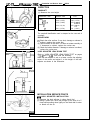
INSPECTION
EGR VALVE
(1) Check EGR valve for sticking or carbon deposits.
If such conditions exist, clean or replace EGR valve.
(2) Connect a hand vacuum pump to the nipple of EGR valve
and plug other nipple.
(3) Apply a vacuum of 500 mmHg (19.7 in. Hg) to make sure
that a vacuum is maintained. If there is a leak, replace the
EGR valve. In addition, check the valve for its opening and
closing by applying and removing a vacuum.
6EMO3RL
I
INJECTORS
(1) Using an ohmmeter (circuit tester), test for continuity
between terminals of injector; the circuit should be closed.
If failure is detected, replace the injector.
Standard value:
N o n - t u r b o 1 3 - 16 IR [at 20°C (68”F)l
2 - 3 R [at 20°C (68”F)]
Turbo
6FU1920
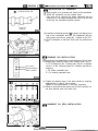
INSTALLATION SERVICE POINTS
I)A4 INJECTOR INSTALLATION
SOHC
(1) Before installing an injector the rubber O-ring must be
lubricated with a drop of clean engine oil to aid in
installation.
6EN0520
(2) Install the injectors from the top end into the fuel rail.
Be careful not to damage the O-ring during installat.ion.
DOHC
6EN0521
I)B4 FUEL PRESSURE REGULATOR INSTALLATION
(1) Before installing the pressure regulator the O-ring must be
lubricated with a drop of clean engine oil to aid in
installation.
1 TSB Revision
11 c-50
4G6 ENGINE <1992> - Throttle Body
THROTTLE BODY
DISASSEMBLY AND REASSEMBLY
SOHC for EXPO
Disassembly steps
1. Accelerator wire bracket
@8 *A4 2. Throttle position sensor
3. Idle air control motor
4. Throttle valve set screw
5. Throttle body
OBO
1.4 ft.lbs.
6FU1657
SOHC for GALANT/TRUCK
3.5 Nm
2.5 ft.lbs.
2Nm
1.4 ft.lbs.
Disassembly steps
$@ *A4 1. Throttle position sensor
2. Idle speed control motor
3. Throttle valve set screw
4. Throttle body
(30
6FU1292
TSB Revision
4G6 ENGINE <1992> - Throttle Body
IIC-51
DOHC
2Nm
1.4ft.lbs.
5
Disassembly steps
(IAI) *AC I. Throttle position sensor
2. Idle air control motor (stepper motor)
OAO
3. Closed throttle position switch
4. Adjusting nut
5. Throttle body
(PO
1 TSB Revision
6FU1427
11 C-52
4G6 ENGINE <1992> - Throttle Bodv
DISASSEMBLY SERVICE POINTS
QAo
THROTTLE POSITION SENSOR AND IDLE AIR/
SPEED CONTROL MOTOR REMOVAL
(1) Do not disassemble the sensor and motor.
(2) Do not immerse the sensor and motor in cleaning solvent.
Clean them with shop towel.
~BI) THROTTLE BODY REMOVAL
(1) Do not remove the throttle valve.
(2) Check if the vacuum port or passage is clogged. Use
compressed air to clean the vacuum passage.
Red cl
Blue
MD998463
7FUO29(1
MD998463
7FUO29C
Operational Check
(1) Connect Test Harness to the idle air control motor
connector.
(2) Connect the positive 0 terminal of 6 volt battery to white
clip and green clip of Test Harness.
MD998463
7F11007F
TSB Revision
4G6 ENGINE <1992> - Throttle Bodv
7FUO295
position sensor
connector
6FU125i
Idle speed control
(3) Holding the idle air control motor as shown in the
illustration, connect the negative 0 terminal of the power
supply to each clip as described in the following steps, and
check whether or not a vibrating feeling (a feeling of very
slight vibration of the stepper motor) is generated as a
result of the activation of the stepper motor.
@ Connect the negative 0 terminal of the power supply to
the red and black clip.
@ Connect the negative 0 termi.nal of the power supply to
the blue and black clip.
@ Connect the negative 0 terminal of the power supply to
the blue and yellow clip.
@ Connect the negative 0 terminal of the power supply to
the red and yellow clip.
@ Connect the negative 0 terminal of the power supply to
the red and black clip.
@ Repeat the tests in sequence from @ to 0.
(4) If, as a result of these tests, vibration is detected, the
stepper motor can be considered to be normal.
IDLE SPEED CONTROL MOTOR POSITION SENSOR SOHC for GALANT and TRUCK
(1) Measure the resistance between terminals @ and @
Standard value: 4 - 6 kQ
(2) Disconnect the idle speed control motor connector.
(3) Connect DC 6V between terminals @ and @ of the idle
speed control motor connector, and then measure the
resistance between terminals @ and @ of the idle speed
control motor position sensor connector when the idle
speed control motor is activated (caused to extend and
retract).
Standard value: It should decrease smoothly as the idle
speed control motor plunger retracts.
Caution
Apply only a 6V DC or lower voltage. Application of
higher voltage could cause locking of the motor gears.
(4) If there is a deviation from the standard value, or if the
change is not smooth, replace the idle speed control motor
assembly.
6FU125:
TSB
IlC-53
Revision
1 IC-54
466 ENGINE <1992> - Throttle Body
REASSEMBLY SERVICE POINTS
I)A4 THROTTLE POSITION SENSOR INSTALLATlON SOHC FOR EXPO
(1) Install the throttle position sensor to the throttle body as
shown in the illustration.
(2) Turn the throttle position sensor 90” counterclockwise to
set it in position and tighten the screws.
Throttle position
sensor output
Ground
Closed throkle position
switch
\
Throttle position
sensor power
7FUO535
(3) Connect a circuit tester between @ (ground) and @
(output), or between @(output) and @ (power). Then make
sure that the resistance changes smoothly when the
throttle valve is slowly moved to the fully open position.
(4) Check for continuity between terminals @ (closed throttle
position switch) and @ (ground) with the throttle valve both
fully closed and fully open.
I Throttle valve position
Continuity
I Fully closed
I
1
I
Conductive
I
Fully oDen
I
Non-conductive
I
If there is no continuity with the throttle valve fully closed,
turn the throttle position sensor clockwise, and then check
again.
(5) If the above specifications are not met, replace the throttle
position sensor.
#B4 THROTTLE POSlTlON SENSOR INSTALLATION GALANT, ECLIPSE, MIRAGE, TRUCK
(1) Install the throttle position sensor to the throttle body as
shown in the illustration.
TSB Revision
I
466 ENGINE <1992> - Throttle Bodv
IlC-55
(2) Turn the throttle position sensor 90” clockwise to set it and
tighten the screws.
I
Throttle position
sensor power
round
(3) Connect a circuit tester between @ (ground) and @
(output), or between @ (output) and @ (power). Then,
make sure that the resistance changes smoothly when the
throttle valve is slowly moved to the fully open position.
Throttle position
sensor output
7FUO535
TSB Revision
11 C-56
466 ENGINE <1992> - Intake Manifold
INTAKE MANIFOLD
REMOVAL AND INSTALLATION - SOHC
(RWD)
18 Nm
13 ftlbs.
(FWD)
9
18 Nm
.- ._...
14ttlbs.
\
\ “w-4
‘\
30 Nm
22 ft.lbs.
T34
18 Nrn
13 ftlbs.
u wrn
Ilklm
8 ftlbs.
18 Nm
13 ftlbs.
13 ftlbs.
11
2iNm
16 ft.lbs.
Removal steps
1. Water hose
2. Water hose
efl4 3. Engine coolant temperature gauge unit
*Cg 4. Engine coolant temperature sensor
5. Water outlet fitting
eB4 6. Gasket
7. Thermostat
8. Intake manifold plenum stay
9. Intake manifold plenum
10. Intake manifold plenum gasket
11. Intake manifold stay
12. Engine hanger
13. Intake manifold
14. Intake manifold gasket
6lN0109
TSB Revision
IIC-57
4G6 ENGINE <1992> - Intake Manifold
{EMOVAL AND INSTALLATION - DOHC
(TO turbocharger) ;Xzr, ,, Nm
4
i
- 8 ft.lbs.
eg
Li
(To oil cooler) Q
d
Removal steps
1. Water hose
2. Water hose
3. Water hose (turbo)
4. Water hose (turbo)
*DC 5. Engine coolant temperature gauge unit
#Q 6. Engine coolant temperature sensor
7. Water outlet fitting
+fl4 8. Gasket
9. Thermostat
10. Thermostat case
11. Gasket
20 ftlbs.
12. Intake manifold stay
+A4 13. Intake manifold
14. Intake manifold gasket
6ENO460
TSB Revision
11 C-58
4G6 ENGINE <1992> - Intake Manifold
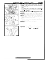
INSTALLATION SERVICE POINTS
*A4 INTAKE MANIFOLD INSTALLATION - DOHC
(1) Tighten the intake manifold bolts. Note that the bolts
installed at the locations indicated in the illustration are
tightened to a different torque.
6lNOO49
eB4
WATER OUTLET FITTING GASKET INSTALLATION
(FOR RUBBER COATED METAL GASKET ONLY)
(1) Install the water outlet fitting gasket with its “UP” mark
facing up (toward the water outlet fitting side).
ec4 SEALANT APPLICATION TO ENGINE COOLANT
TEMPERATURE SENSOR
Specified sealant:
3M Nut Locking Part No. 4171 or equivalent
Sealant
eD4 SEALANT APPLICATION TO ENGINE COOLANT
TEMPERATURE GAUGE UNIT
Specified sealant: 3M ATD Part No. 8660 or equivalent
Sealant
SEN0092
TSB Revision
4G6 ENGINE <1992> - Exhaust Manifold and Water Pumn
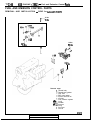
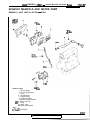
EXHAUST MANIFOLD AND WATER PUMP
REMOVAL AND INSTALLATION - SOHC
14 Nm*
10 ftlbs.
18 Nm
13 ft.lbs.
14 Nm
10 ft.lbs.
24Nm
17 ft.lbs.
Removal steps
1. Oil level gauge
2. Oil level gauge guide
3. O-ring
4. Heat protector
5. Engine hanger
6. Exhaust manifold
7. Exhaust manifold gasket
#A4 8. Water inlet pipe
+A4 9. O-ring
10. Water pump
11. Water pump gasket
NOTE
* : GALANT and EXPO
**: TRUCK
6EN0647
1 TSB Revision
11 C-60
466 ENGINE <1992> - Exhaust Manifold and Water Pump
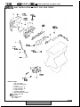
IEMOVAL AND INSTALLATION - DOHC FOR NON-TURBO
28 Nm
20 ftlbs.
I
14 Nm
10 ft.lbs.
10 ft.lbs. 4
60 Nm
43 ftlbs.
14 Nm
10 ft.lbs. 4
24 Nm
17 ft.lbs.
Removal steps
1. Oil level gauge
2. Oil level gauge guide
3. O-ring
4. Heat protector “A”
5. Heat protector “B”
6. Engine hanger
7. Exhaust manifold
8. Exhaust manifold gasket
+A4 9. Water inlet pipe
)A4 10. O-ring
11. Water pump
12. Gasket
6EN0646
TSB Revision
4G6 ENGINE <1992> - Exhaust Manifold and Water Pump
1 X-61
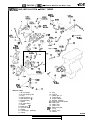
IEMOVAL AND INSTALLATION - DOHC TURBO
43Nm
31 ft.lbs.
14 Nm
60
43
- 11 Nm
8 ftlbs.
14 Nm
10 ft.lbs.
16
43Nm
6
24 Nm
17 ft.lbs.
9Nm
7 ft.lbs.
Removal steps
1. Oil level gauge
2. Oil level gauge guide
3. O-ring
4. Heat protector “A”
5. Heat protector “B”
6. Exhaust fitting
7. Gasket
8. Air outlet fitting
9. Gasket
I 0. Water pipe “B”
11. Oil return pipe
12. Gasket
13. Turbocharger assembly
14. Gasket
TSB Revision
15. Ring
16. Oil pipe
17. Water pipe “A”
18. Turbocharger
19. Engine hanger
20. Exhaust manifold
21. Exhaust manifold gasket
22. Water pipe
23. Water hose
24. Water hose
#A4 25. Water inlet pipe
*A4 26. O-ring
27. Water pump
28. Gasket
6EN0649
11 C-62
4G6 ENGINE <1992> - Exhaust Manifold and Water Pump
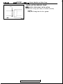
INSTALLATION SERVICE POINT
I)A4 WATER PIPE/O-RING INSTALLATION
O-ring
(1) Wet the O-ring (with water) to facilitate assembly
Caution
Keep the O-ring free of oil or grease.
_jlr
6EN059
TSB
Revision
4G6 ENGINE <1992> - Turbocharger
1
K-63
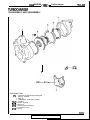
TURBOCHARGER
DISASSEMBLY AND REASSEMBLY
Disassembly steps
inspection of turbocharger waste gate
W4
actuator operation
1. Snap pin
2. Turbocharger waste gate actuator
+E4 3. Coupling
*DC 4. Turbine housing
*C4 5. Snap ring
eB4 6. Turbine wheel assembly
7. Compressor cover
+A4 8. O-ring
6lNOO52
TSB Revision
11 C-64
4G6 ENGINE <1992> - Turbocharger
INSPECTION
6lN0055
Comr,
whekl
3EN020E
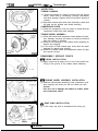
TURBINE HOUSING
(1) Check the housing for traces of contact with the turbine
wheel, cracks due to overheating, pitching, deformation
and other damage. Replace with a new turbine housing if
cracked.
(2) Operate the waste gate valve lever manually to check that
the gate can be opened and closed smoothly.
COMPRESSOR COVER
(1) Check the compressor cover for traces of contact with the
compressor wheel and other damage.
TURBINE WHEEL ASSEMBLY
(1) Check the turbine and compressor wheel blades for bend,
burr, damage, corrosion and traces of contact on the back
side and replace if defective.
(2) Check the oil passage of the turbine wheel assembly for
deposit and clogging.
(3) In the case of water cooled type, check also the water
passage for deposit and clogging.
(4) Check the turbine wheel and compressor wheel for light
and smooth turning.
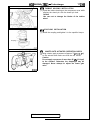
REASSEMBLY SERVICE POINTS
#A4 O-RING INSTALLATION
(1) Apply a light coat of engine oil to a new O-ring and fit the
O-ring in the groove of the turbine wheel assembly.
*Bg
TURBINE WHEEL ASSEMBLY INSTALLATION
(1) Install the turbine wheel assembly to the compressor cover
while aligning the dowel pin with the dowel pin hole.
Caution
Use care not to damage the blades of turbine wheel
and compressor wheel.
Chamfered 1
assembly
+c4 SNAP RING INSTALLATION
(1) Fit the snap ring with its chamfered side facing up.
6lN0070
1 TSB Revision
4G6 ENGINE <1992> - Turbocharger
11 C-65
eD4 TURBINE HOUSING INSTALLATION
(1) Install the turbine housing on the compressor cover while
aligning the dowel pin with the dowel pin hole.
Caution
Use care not to damage the blades of the turbine
wheel.
I)E4 COUPLING INSTALLATION
(1) Install the coupling and tighten it to the specified torque.
Coupling
eF4
WASTE GATE ACTUATOR OPERATION CHECK
(1) Using a tester, apply a pressure of approx. 72 kPa (10.3 psi)
to the actuator and make sure that the rod moves.
Caution
Do not apply a pressure of more than 85 kPa (12.4 psi)
to the actuator. Otherwise, the diaphragm may be
damaged. Never attempt to adjust the waste gate
valve.
6lN005!
TSB Revision
llC=66
4G6 ENGINE <1992>
- Rocker Arms and Camshaft - SOHC
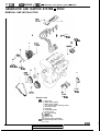
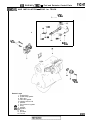
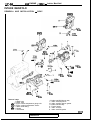
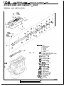
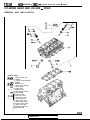
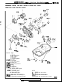
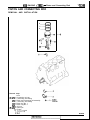
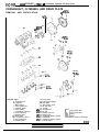
ROCKER ARMS AND CAMSHAFT - SOHC
REMOVAL AND INSTALLATION
Q-----7
nemoval steps
1. Breather hose
2. P.C.V. hose
3. Packing
4. Oil seal
5. Rocker cover
6. Gasket
eG4 7. Semi-circular packing
8. Rocker arms and rocker shafts
9. Rear bearing cap
eC4 10. Rocker arm D
11. Spring
v-EC 12. Rocker arm D
*Dir 13. Bearing-cap No. 4
‘34 14. Rocker arm C
C4 15.
arm C
_^ Rocker
^
rq I/. Beanng cap No. 3
I;4 18.
arm D
.- Rocker
C4
+04
+C4
eC4
20. Rocker arm D
21. Bearing cap No. 2
22. Rocker arm C
23. Rocker arm C
24. Spring
+B4 25. Wave washer
#A4 26. Right rocker shafts
*A4 27. Left rocker shafts
28. Front bearing cap
(IAO +E4 29. Lash adjuster
+F4 30. Oil seal
31. Camshaft
TSB Revision
1
- - - F&l~lluC /1663\ _ Rack r Arms
I ‘K-67
and Camshaft - SOW
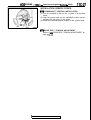
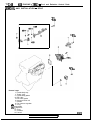
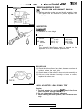
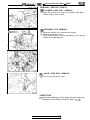
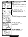
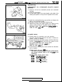
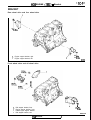
REMOVAL SERVICE POINT
(IAO ROCKER ARM AND CAMSHAFT REMOVAL
MD998443-01
I
(1) Before removing rocker arms and shafts assembly, install
the special tool as illustrated to prevent adjuster from
dropping.
6EN056E
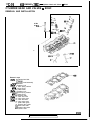
INSPECTION
CAMSHAFT
(1) Measure the cam height
1 Identification mark (Standard value
D: Intake
Exhaust
AR: Intake
Exhaust
42.40
42.40
44.53
44.53
(1.6692)
(1.6692)
(1.7531)
(1.7531)
1 Limit
41.90
41.90
44.03
44.03
I
(1.6496)
(1.6496)
(1.7335)
(I .7335)
NOTE
The camshaft identification mark is stamped on the
opposite end of the camshaft sprocket side.
ROCKER ARM
(1) Check the roller surface. If any dent, damage or seizure is
evident, replace the rocker arm.
(2) Check rotation of the roller. If it does not rotate smoothly or
if looseness is evident, replace the rocker arm.
(3) Check the inside diameter. If damage or seizure is evident,
replace the rocker arm.
7EN006L.
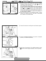
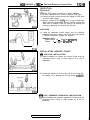
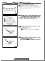
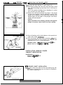
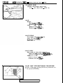
LASH ADJUSTER LEAK DOWN TEST
Caution
1. The lash adjuster is a precision part. Keep it free from
dust and other foreign matters.
2. Do not disassemble the lash adjusters.
3. When cleaning the lash adjusters, use clean diesel fuel
only.
TSB Revision
1
IIC-68
4G6 ENGINE <1992> - Rocker Arms and Camshaft - SOHC
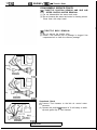
(1) Immerse the lash adjuster in clean diesel fuel.
(2) While lightly pushing down the inner steel ball using a small
wire, move the plunger up and down four or five times to
bleed air.
Use of the retainer facilitates the air bleeding of a rocker
arm mounted type lash adjuster.
(3) Remove the small wire and press the plunger. If the plunger
is hard to be pushed in, the lash adjuster is normal. If the
plunger can be pushed in all the way readily, bleed the lash
adjuster again and test again. If the plunger is still loose,
replace the lash adjuster.
Caution
Upon completion of air bleeding, hold the lash adjuster
upright to prevent inside diesel fuel from spilling.
6EN057t
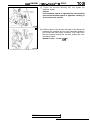
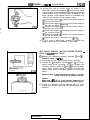
Division = 1 mm LO4 in.)
(4) After air bleeding, set the lash adjuster on the special tool
(Leak down tester MD998440).
(5) After the plunger has gone down somewhat (.2 - .5 mm),
measure time taken for it to go down 1 mm. Replace if the
measured time is out of the specification.
Standard value: 4 - 20 seconds / 1 mm (.04 in.)
[Diesel fuel at 15 - 20°C (59 - 68”F)]
7EN0438
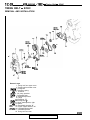
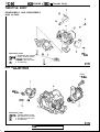
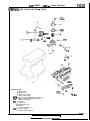
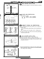
INSTALLATION SERVICE POINTS
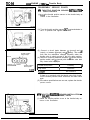
CAMSHAFT IDENTIFICATION
Identification:
E X P O / GALANT A R
TRUCK
D
Notch
+A4
ROCKER SHAFT INSTALLATION
(1) Insert the rocker arm shaft into the front bearing cap with
the notch on the shaft facing up, and insert the installation
bolt without tightening it.
TSB Revision
‘I
4G6 ENGINE <1992> - Rocker Arms and Camshaft - SOHC
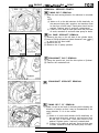
I)B+
Wave
washer
11 C-69
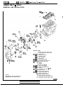
WAVE WASHER INSTALLATION
(1) Install the wave washer in the correct direction as shown.
side rocker arm
-
6EN057Z
identification
b Timing belt side
No. 1 No. 2
No. 1
No. 2
I)c4 ROCKER ARM IDENTIFICATION
Identification mark:
1 - 3
for No. 1 and 3 cylinders
No. 3 No. 4
2-4
N o . 3 No. 4
6EN055e
Rocker cover
mounting bolt hole
FroAt mark ’ Identification mark
No. 2
No. 3
for No. 2 and 4 cylinders
No. 4
I)D4 CAMSHAFT BEARING CAP IDENTIFICATION
(1) No. 3 bearing cap looks very similar to No. 2 and No. 4
bearing caps.
Use the identification marks shown at left for identification.
NOTE
No. 2 bearing cap is the same as No. 4 bearing cap.
(2) Install the bearing caps with their front marks pointing to
camshaft sprocket side.
6EN0024
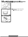
I)Eg
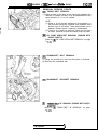
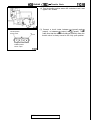
LASH ADJUSTER INSTALLATION
(1) Immerse the lash adjuster in clean diesel fuel.
(2) Using a small wire, move the plunger up and down 4 or 5
times while pushing down lightly on the check ball in order
to bleed out the air.
6EN0421
(3) Insert the lash adjuster to rocker arm, being careful not to
spill the diesel fuel. Use the special tool to prevent adjuster
from falling while installing it.
Lash adjuiter
7EN0174
TSB Revision
I
4G6 ENGINE <1992> - Rocker Arms and Camshaft - SOHC
I)F4 CAMSHAFT OIL SEAL INSTALLATION
I)G4
Apply sealant
DEN0052
IOmm
Semi-circular
packing
Gasket r$ of
cvlinder head
6EN042
TSB Revision
SEMI-CIRCULAR PACKING INSTALLATION
Specified sealant:
3M ATD Part No. 8660 or equivalent
4G6 ENGINE <1992>
- Camshafts and Rocker Arms - DOHC
1 IC-71
CAMSHAFTS AND ROCKER ARMS - DOHC
REMOVAL AND INSTALLATION
6
20 Nm
14 t=t.lbs.-
11 Nm
8 ftlbs.
Removal steps
fiC4 1. Bearing cap rear
#Q 2. Bearing cap front
+04 3. Camshaft oil seal
#C4 4. Bearing cap No. 5
eC4 5. Bearing cap No. 2
eC4 6. Bearing cap No. 4
eC4 7. Bearing cap No. 3
eB4 8. Camshaft
9. Rocker arm
*A4 10. Lash adjuster
11. Oil delivery body
6EN0524
TSB Revision
11 C-72
4G6 ENGINE <1992>
- Camshafts and Rocker Arms - DOHC
INSPECTION
CAMSHAFT
(1) Measure the cam height.
Identification mark
Standard value
Limit
35.49 (1.3972)
35.20 (1.3858)
34.99 (1.3776)
34.70 (I .3661)
35.49 35.20 (1.3972) (1.3858)
34.99 34.70 (1.3776) (1.3661)
35.91 (1.3744)
34.41 (1.3547)
Intake
AD
I3.CF.F
Exhaust
2
E.F
Roller
Tip
I
6EN018!
Scale = 1 mm (.039 in.)
M[
\
The camshaft identification mark is stamped on the rear end of
camshaft.
ROCKER ARM
(1) Check the roller surface. If any dent, damage or seizure is
evident, replace the rocker arm.
(2) Check rotation of the roller. If it does not rotate smoothly or
if looseness is evident, replace the rocker arm.
(3) Check the inside diameter. If damage or seizure is evident,
replace the rocker arm.
LASH ADJUSTER LEAK DOWN TEST
Refer to “LASH ADJUSTER LEAK DOWN TEST” on pages
1 lC-67 and 11 C-68 . Also note the following.
When the lash adjuster is set on a tester, remove the adjusting
screw of the tester and adjust it to the height of the lash
adjuster as shown in the illustration.
6EN035
Nut
6EN035
INSTALLATION SERVICE POINTS
*A4 LASH ADJUSTER INSTALLATION
(1) Immerse the lash adjuster in clean diesel fuel.
(2) Using a small wire, move the plunger up an down 4 to 5
times while pushing down lightly on the check ball in order
to bleed out the air.
6EN042
TSB Revision
4G6 ENGINE <1992> - Camshafts and Rocker Arms - DOHC
I)64 INSTALLATION OF CAMSHAFT
(1) Apply engine oil to journals and cams of the camshafts.
(2) Install the camshafts on the cylinder head.
Use care not to confuse the intake camshaft with the
exhaust one. The intake camshaft has a slit on its rear end
for driving the crankshaft position sensor.
Camshaft sprocket side
Intake side
camshaft
1 IC-73
6EN0289
(3) Install the crankshaft sprocket B or spacer and flange to an
end of the crankshaft, and turn the crankshaft until the
timing marks are lined up, setting No. 1 cylinder to the TDC.
(4) Set the camshafts so that their dowel pins are positioned at
top.
Dowel pin
c
I)c4 BEARING CAP INSTALLATION
Cap number
Symbol identifying
intake or exhaust
(1) According to the identification mark stamped on top of each
bearing cap, install the caps to the cylinder head. Only “L”
or “R” is stamped on No. 1 bearing cap. Cap No. is stamped
on No. 2 to No. 5 bearing caps. No. 6 bearing cap has no
stamping.
I: For intake camshaft side
E: For exhaust camshaft side
6EN046r
(2) Tighten the bearing caps in the order shown by torquing
progressively in two to three stages.
Tighten to the specification in the final sequence.
(3) Check to ensure that the rocker arm is held in position on
the lash adjuster and valve stem end.
- Camshaft sprocket side
0
3
0
0
@
0
6EN019i
I)D4 CAMSHAFT OIL SEAL INSTALLATION
I
A
),\
\c
6EN0651
levision
11 c-74
4G6 ENGINE <1992>
- Cylinder Head and Valves - SOHC
CYLINDER HEAD AND VALVES - SOHC
REMOVAL AND INSTALLATION
95 Nm
69 fklbs. --1
0
1
e--2
III184
RI7
v
Removal steps
(IA~J I)E4 ;. C&i;;;; head bolt
3: Cylinder head assembly
$04 4. Gasket
@I$ I)C4 5. Retainer lock
6. Valve spring retainer
$64 7. Valve spring
8. Intake valve
QBr) SC4 9. Retainer lock
10. Valve spring retainer
I)B+ 11. Valve spring
12. Exhaust valve
(A@ #A4 13. Valve stem seal
14. Valve spring seat
(10) +A4 15. Valve stem seal
16. Valve spring seat
17. Intake valve guide
18. Exhaust valve guide
19. Intake valve seat
20. Exhaust valve seat
21. Cylinder head
6EN0309
TSB Revision
4G6 ENGINE <1992>
- Cvlinder Head and Valves - SOHC
IIC-75
REMOVAL SERVICE POINTS
PRECAUTION FOR REMOVED PARTS
(1) Keep removed parts in order according to the cylinder
number and intake/exhaust.
OAo CYLINDER HEAD BOLT REMOVAL
(1) Using the special tool, loosen the cylinder head bolts.
Loosen evenly, little by little.
tJB0 RETAINER LOCK REMOVAL
(1) Using the special tool, compress the spring.
(2) Remove the retainer locks.
Keep removed parts in order according to the cylinder
number and intake/exhaust.
a@ VALVE STEM SEAL REMOVAL
(1) Do not reuse valve stem seal.
1 TSB Revision
1 IC-76
466 ENGINE <1992> - Cvlinder Head and Valves - SOHC
INSPECTION
CYLINDER HEAD
(1) Check the cylinder head gasket surface for flatness by
using a straightedge in the directions of A through G shown
in the illustration.
Standard value: 0.05 mm (JO20 in.)
Limit: 0.2 mm (008 in.)
(2) If the service limit is exceeded, correct to meet the
specification.
Grinding limit: “0.2 mm (008 in.)
Caution
* Total resurfacing depth of both cylinder head and
cylinder block.
Cylinder head height (Specification when new):
89.9 - 90.1 mm (3.539 - 3.547 in.)
1
1 6EN0542
I
Free
height
Gu:de I.D.
Guide O.D.
1 EN0264
1 EN0279
VALVE
(1) Check the valve face for correct contact. If incorrect, reface
using a valve refacer. The valve seat contact should be
maintained uniform at the center of the valve face.
(2) If the margin exceeds the service limit, replace the valve.
Standard value:
1.2 mm LO47 in.)
Intake
Exhaust
2.0 mm (079 in.)
Limit:
0.7 mm (.028 in.)
Intake
1.5 mm (059 in.)
Exhaust
VALVE SPRING
(1) Measure the free height of spring and, if it is smaller than
the limit, replace.
Identification color: White
Standard value: 49.8 mm (1.961 in.)
Limit: 48.8 mm (1.922 in.)
(2) Measure the squareness of the spring and, if the limit is
exceeded, replace.
Standard value: 2“ or less
Limit: Max. 4”
VALVE GUIDE
(1) Measure the clearance between the valve guide and valve
stem. If the limit is exceeded, replace the valve guide or
valve, or both.
Standard value:
0.02 - 0.06 mm (0008 - .0024 in.)
Intake
0.05 - 0.09 mm (0020 - .0035 in.)
Exhaust
Limit:
0.10 mm (.004 in.)
Intake
Exhaust
0.15 mm (006 in.)
1 TSB Revision
4G6 ENGINE <1992> - Cylinder Head and Valves - SOHC
IIC-77
VALVE SEAT RECONDITIONING PROCEDURE
(1) Before correcting the valve seat, check for clearance
between the valve guide and valve and, if necessary,
replace the valve guide.
(2) Using the special tool or seat grinder, correct to obtain the
specified seat width and angle.
(3) After correction, valve and valve seat should be lapped with
a lapping compound.
6EN049
VALVE SEAT REPLACEMENT PROCEDURE
0.5 - 1 mm (.020- ,039 in.)
(1) Cut the valve seat to be replaced from the inside to thin the
wall thickness. Then, remove the valve seat.
0.5-I mm
(.020-,039 in.)
1 EN027~
1 EN02
VALVE GUIDE REPLACEMENT PROCEDURE
Installation
Removal
Press
a
Press
a
MD9981 15-01
Push rod
Valve
guide
(2) Rebore the valve seat hole in the cylinder head to a selected
oversize valve seat diameter.
Seat ring hole diameter: See “Service Specifications”
on page IIC-10.
(3) Before fitting ttie valve seat, either heat the cylinder head
up to approximately 250°C (482°F) or cool the valve seat in
liquid nitrogen, to prevent the cylinder head bore from
galling.
(4) Using a valve seat cutter, correct the valve seat to the
specified width and angle.
See “VALVE SEAT RECONDITIONING PROCEDURE”.
6]
MD998115
-01
(1) Using the special tool and a press, remove the valve guide
toward cylinder head gasket surface.
(2) Rebore valve guide hole to the new oversize valve guide
outside diameter.
Valve guide hole diameter: See “Service Specifications” on page IIC-10.
Valve
guide
6EN054
NOTE
Do not install a valve guide of the same size again.
(3) Using the special tool, press-fit the valve guide, working
from the cylinder head top surface.
(4) After installing valve guides, insert new valves in them to
check for sliding condition.
(5) When valve guides have been replaced, check for valve
contact and correct valve seats as necessary.
TSB Revision
1 IC-78
466 ENGINE <1992> - Cylinder Head and Valves - SOHC
INSTALLATION SERVICE POINTS
I)A4 VALVE STEM SEAL INSTALLATION
MD998729-01
(1) Install the valve spring seat.
4-l
5ENOOl E
1
(2) Using the special tool, install a new stem seal to the valve
guide.
Caution
Do not reuse the valve stem seal.
61
;
I)& VALVE SPRING INSTALlATlON
(I) Direct the valve spring end with identification color end
toward the spring retainer.
Identification
color
Stem seal
)
LSpring seal
I
6EN043i I
A
I)c4 RETAINER LOCK INSTALLATION
(1) Using the special tool, compress the valve spring and insert
the retainer lock into position.
TSB Revision
4G6 ENGINE <1992> - Cylinder Head and Valves - SOHC
IIC-79
I)D4 CYLINDER HEAD GASKET IDENTIFICATION
Identification mark
Identification mark:
4663 . . . . . 63
4664 . . . . . 64
Caution
Do not apply sealant to cylinder head gasket.
6EN054 5
I)E4 CYLINDER HEAD BOLT INSTALLATION
(=I
(1) Tighten the cylinder head bolts in the sequence shown.
Each bolt should be tightened in two to three steps,
torquing progressively. Tighten to the specified torque in
the final sequence.
Camshaft sprocket side
6EN05413
MD998051-01
OPTIONAL\ -
TSB Revision
11 C-80
466 ENGINE <1992> - Cylinder Head and Valves - DOHC
CYLINDER HEAD AND VALVES - DOHC
REMOVAL AND INSTALLATION
Removal steps
OArJ )E4 1. Cylinder head bolt
2. Washer
3. Cylinder head assembly
)D4 4. Gasket
(IBM *Cc 5. Retainer lock
6. Valve spring retainer
7. Valve spring
8. Intake valve
9. Retainer lock
10. Valve spring retainer
II. Valve spring
12. Exhaust valve
13. Valve stem seal
14. Valve spring seat
15. Valve stem seal
6. Valve spring seat
17. Intake valve guide
18. Exhaust valve guide
19. Intake valve seat
20. Exhaust valve seat
21. Cylinder head
6EN0196
1 TSB Revision
I
4G6 ENGINE <1992> - Cylinder Head and Valves - DOHC
1 W-81
REMOVAL SERVICE POINTS
OAo CYLINDER HEAD BOLT REMOVAL
(1) Using the special tool, loosen the cylinder head bolts.
Loosen evenly, little by little.
OBo RETAINER LOCK REMOVAL
MD998735-01
(1) Using the special tool, compress the spring.
(2) Remove the retainer locks.
Keep removed parts in order according to the cylinder
number and intake/exhaust.
($0 VALVE STEM SEAL REMOVAL
(1) Do not reuse the stem seals.
INSPECTION
(1) Only features differing from the single camshaft engine are
described in the following. (Refer to Pages 1 lC-76.)
TSB Revision
11 C-82
4G6 ENGINE <1992> - Cylinder Head and Valves - DOHC
CYLINDER HEAD
Cylinder head height (when new):
131.9 - 132.1 mm (5.193 - 5.201 in.)
VALVE
Margin:
Intake 1.0 mm (.039 in.)
Exhaust I.5 mm (.059 in.)
Limit:
Intake 0.7 mm (.028 in.)
Exhaust 1.0 mm (.039 in.)
VALVE SPRING
Free height: 48.3 mm (1.902 in.)
Limit: 47.4 mm (I.866 in.)
Squareness: 1.5” or less
Limit: Max. 4”
VALVE GUIDE
Valve guide to valve stem clearance:
Intake 0.02 - 0.05 mm (.OOOS - .0020 in.)
Exhaust 0.05 - 0.09 mm (.0020 - .0035 in.)
Limit:
Intake 0.10 mm (.004 in.)
Exhaust 0.15 mm (.006 in.)
VALVE SEAT RECONDITIONING PROCEDURE
(1) Refer to Page 11 C-77, noting that the only difference is in
the special tool (Cutter).
6EN0491
TSB Revision
4G6 ENGINE <1992> - Cylinder Head and Valves - DOHC
1 IC-83
VALVE SEAT REPLACEMENT PROCEDURE
(1) Refer to Page 1 IC-77 noting that the only difference is in
the reboring size.
Intake valve seat hole diameter
0.3 mm (.012 in.) O.S. . . . . . . . . . . . . . . . . . . . . 35.30- 35.33 mm
(1.3898 - I .3909 in.)
0.6 mm (.024 in.) O.S. . . . . . . . . . . . . . . . . . . . . 35.60 - 35.63 mm
(1.4016- 1.4028 in.)
Exhaust valve seat hole diameter
0.3 mm (.012 in.) O.S. . . . . . . . . . . . . . . . . . . . . 33.30- 33.33 mm
(1.3110- 1.3122 in.)
33.60- 33.63 mm
.
.
.
.
.
.
.
.
.
.
.
.
.
.
.
.
.
.
.
.
0.6 mm (024 in.) O.S.
(1.3228- 1.3240 in.)
VALVE GUIDE REPLACEMENT PROCEDURE
(1) Refer to Page 11 C-77, noting that there are differences in
the diameter of the valve guide hole as well as in the
guide’s installed height.
Valve Guide Hole Diameter
0.05 mm (.002 in.) O.S. . . . . . . . . . . . . . . . . 12.05 - 12.07 mm
(.4744 - .4752 in.)
12.2512.27 mm
.
.
.
.
.
.
.
.
.
.
.
.
.
.
.
.
0.25 mm (.OIO in.) O.S.
(.4823 - 4831 in.)
0.50 mm (.002 in.) O.S. . . . . . . . . . . . . . . . . 12.50- 12.52 mm
(.4921- .4929 in.)
INSTALLATION SERVICE POINTS
+A4 VALVE STEM SEAL INSTALLATION
Valve
seat
I
6EN020!
(1) Install the valve spring seat.
(2) Using the special tool, install a new stem seal to the valve
guide.
Caution
Do not reuse the valve stem seal.
h
I)B4 VALVE SPRING INSTALLATION
Identificationcolor
(1) Install the valve spring so that its end with identification
color is positioned on the rocker arm end.
TSB Revision
11 C-84
4G6 ENGINE <1992> - Cylinder Head and Valves - DOHC
I)& RETAINER LOCK INSTALLATION
(1) Using the special tool, compress the valve spring and insert
the retainer lock into position.
I)D4 CYLINDER HEAD GASKET IDENTIFICATION
Identification mark:
I6 4661
2 0 4663
6EN0209
#Eg CYLINDER HEAD BOLT INSTALLATION
a Camshaft sprocket side
i
6
6
b
6
6
(1) Tighten the cylinder head bolts in the sequence shown.
Each bolt should be tightened in two to three steps,
torquing progressively. Tighten to the specified torque in
the final sequence.
6EN0211
TSB Revision
4G6
ENGINE <1992> - Front Case, Silent Shaft and Oil Pan
1
X-85
FRONT CASE, SILENT SHAFT AND OIL PAN
REMOVAL AND INSTALLATION
22 **
24 Nm ****
40 ftlbs.
Removal steps
1. Oil filter
2. Oil cooler bolt***
3. Oil cooler***
4. Drain plug
5. Drain plug gasket
(IAO+N~ 6. Oil pan
7. Oil screen
8. Oil screen gasket
OBrJ )EC 9. Flange nut
10. Oil pump sprocket**
@IQ )MCl 1. Plug
12. O-ring
@IQ )L~I 13. Flange bolt
14. Oil filter bracket
15. Oil filter bracket gasket
*KC 16. Front case
17. Front case gasket
18. Silent shaft, left**
19. Silent shaft, right**
(IEIJ +,I4 20. Silent shaft, front bearing**
(IFO +I4 21, Silent shaft, rear bearing. left**
(IGO *H4 22. Silent shaft, rear bearing, right**
NOTE
*
: DOHC
**
: Engine with silent shafts
xxx : Engine with turbocharger
**** : Engine without silent shafts
*****: Engine with air-cooling type oil cooler
6EN0533
1 TSB Revision
I
IIC-86
466 ENGINE <1992> - Front Case, Silent Shaft and Oil Pan
19=-Q&
2ow
33 Nm -189
24 ft.lbs.
1
m5\
?
?
45 Nm
33 ft.lbs.
:
***** 55 Nm
40 ft.lbs.
1. Oil cooler by-pass valve*****
+G4 2. Oil pressure switch
eF4 3. Oil pressure gauge unit
;. pm
:55 Nm
40 ft.lbs.
$04
I)D4
eC4
*Bg
NOTE
*
: DOHC
**
: Engine with silent shafts
*** : Engine with turbocharger
**** : Engine without silent shafts
*****: Engine with air-cooling type oil cooler
6: Relief spring
7. Relief plunger
8. Oil filter bracket
9. Oil pump cover
10. Oil pump shaft****
11. Oil pump driven gear
12. Oil pump drive gear
13. Crankshaft,front oil seal
14. Oil p,u,m,p,o~l seal
I)A~ ig. .%%t shaft oil seal**
17: Front case
18. Check valve
19. Oil jet
20. Gasket
6EN0525
1 TSB Revision
4G6 ENGINE <1992> - Front Case, Silent Shaft and Oil Pan
1 IC-87
REMOVAL SERVICE POINTS
aA OIL PAN REMOVAL
Service tool :
(1) Remove the all oil pan bolts.
(2) Drive in the service tool between the cylinder block and oil
pan.
NOTE
Never use a screwdriver or chisel, instead of the service
tool, as a deformed oil pan flange will result in oil leakage.
OlLO583
OlLO584
(IBI) FLANGE NUT REMOVAL
Engine with silent shafts
(ENGINE WITH SILENT SHAFTS)
(1) Remove the plug on the side of the cylinder block.
(2) Insert a Phillips screwdriver [shank diameter 8 mm (.32 in.)]
into the plug hole to lock the silent shaft.
(3) Loosen the oil pump sprocket flange nut.
6EN0563 1
6EN05641
@) PLUG REMOVAL
(1) If the plug is too tight, hit the plug head with a hammer two
to three times, and the plug will be easily loosened.
~DI) FLANGE BOLT REMOVAL
Engine with sile
(ENGINE WITH SILENT SHAFTS)
(1) Referring to ~BIJ (2). lock the silent shaft.
(2) Loosen the flange bolt.
Engine without silent shafts
I
ODo FLANGE NUT REMOVAL
(ENGINE WITHOUT SILENT SHAFTS)
(1) Clamp the oil pump shaft end in a vise.
6EN0339
1 TSB Revision
4G6 ENGINE <1992> - Front Case, Silent Shaft and Oil Pan
(2) Remove the oil pump sprocket nut.
Engine with silent shafts
OEo
SILENT SHAFT FRONT BEARING REMOVAL
(ENGINE WITH SILENT SHAFTS)
Using the special tool, remove the silent shaft front bearing
from the cylinder block.
NOTE
Be sure to remove the front bearing first.
If it has not been removed, the Rear Bearing Puller cannot
be used.
OFr)
LEFT SILENT SHAFT REAR BEARING REMOVAL
(ENGINE WITH SILENT SHAFTS)
Using the special tool, remove the left silent shaft rear
bearing from the cylinder block.
QGo
REAR BEARING REMOVAL
(ENGINE WITH SILENT SHAFTS)
Using the special tool, remove the right silent shaft rear
bearing from the cylinder block.
INSPECTION
FRONT CASE
(1) Check oil holes for clogging and clean if necessary.
(2) Check left silent shaft front bearing section for wear,
damage and seizure. If there is anything wrong with the
section, replace the front case.
(3) Check the front case for cracks and other damage. Replace
cracked or damaged front case.
OIL SEAL
(1) Check the oil seal lip for wear and damage. Replace the oil
seal if necessary.
(2) Check the oil seal lip for deterioration. Replace the oil seal if
necessary.
TSB Revision
4G6 ENGINE <1992> - Front Case, Silent Shaft and Oil Pan
I
Engine with silent shafts
I
DEN0711
IIC-89
SILENT SHAFT (ENGINE WITH SILENT SHAFTS)
(1) Check oil holes for clogging.
(2) Check journal for seizure, damage and contact with bearing.
If there is anything wrong with the journal, replace silent
shaft, bearing or front case assembly.
(3) Check the silent shaft oil clearance. If the clearance is
excessively due to wear, replace the silent shaft bearing,
silent shaft or front case assembly.
Standard value:
Front
Right
0.03 - 0.06 mm (.0012 - .0024 in.)
0.02 - 0.05 mm (.OOOS - .0020 in.)
Left
Rear
Right
0.05 - 0.09 mm (.0020 - .0036 in.)
Left
0.05 - 0.09 mm (.0020 - .0036 in.)
OIL PUMP
(1) Assemble the oil pump gears in the front case and rotate
them to ensure smooth rotation with no looseness.
(2) Ensure that there is no ridge wear on the gear contact
surface of the front case and the oil pump cover.
(3) Check the side clearance
Standard value:
0.08 - 0.14 mm (.0031 - .0055 in.)
Drive gear
0.06 - 0.12 mm (.0024 - .0047 in.)
Driven gear
-
I
6LUOO13
OIL COOLER BYPASS VALVE
(ENGINE WITH AIR COOLING TYPE OIL COOLER)
(1) Make sure that the valve moves smoothly.
(2) Ensure that the dimension (L) measures the standard value
under normal temperature and humidity.
Standard value (L): 34.5 (.358 in.)
(3) The dimension must be the standard value when measured
after the valve has been dipped in 100°C (212°F) oil.
Standard value (L): 40 mm (1.57 in.) or more
6EN0589
Engine with silent shafts
INSTALLATION SERVICE POINTS
I)A4 SILENT SHAFT OIL SEAL INSTALLATION
a
Socket wrench
Front case
N05EX
TSR Revision
(ENGINE WITH SILENT SHAFTS)
IIC-90
4G6 ENGINE <1992> - Front Case, Silent Shaft and Oil Pan
I)64
OIL PUMP OIL SEAL INSTALLATION
6EN0494I
6EN0494
CRANKSHAFT FRONT OIL SEAL INSTALLATION
I)c4
(1) Using the special tool, install the crankshaft front oil seal
into the front case.
I)D4
OIL PUMP DRIVEN GEAR / OIL PUMP DRIVE GEAR
INSTALLATION
(I) Apply engine oil amply to the gears and line up the
alignment marks.
+E4
FLANGE NUT INSTALLATION
(ENGINE WITHOUT SILENT SHAFTS)
Caution
Before installing the flange nut, apply an appropriate
amount of oil to the seating surface.
(I) Clamp the oil pump shaft end in a vise.
IEngine without silent shafts
ml
6EN033Y
Engine without silent shafts
\
\
(2) Tighten the oil pump sprocket nut to the specified torque.
TSB Revision
4G6 ENGINE <1992>
- Front Case, Silent Shaft and Oil Pan
I)F~I
IIC-91
SEALANT APPLICATION TO OIL PRESSURE GAUGE
UNIT
(1) Coat the threads of the oil pressure gauge unit with sealant
and install the unit using the special tool.
Specified sealant: 3M ATD Part No. 8660 or equivalent
Caution
1. Keep the end of threaded portion clear of sealant.
2. Avoid an overtightening.
APP~
3EN0221
I)G4 SEALANT APPLICATION TO OIL PRESSURE
SWITCH
(1) Coat the threads of the oil pressure switch with sealant and
install the switch using the special tool.
Specified sealant: 3M ATD Part No.8660 or equivalent
Caution
1. Keep the end of threaded portion clear of sealant.
2. Avoid an overtightening.
9ENOOSL
I)H4
RIGHT SILENT SHAFT REAR BEARING INSTALLATION (ENGINE WITH SILENT SHAFTS)
(1) Apply engine oil to the outer surface of the bearing.
(2) Using special tools, install the right rear bearing. Make sure
that the oil hole of the bearing is aligned with the oil hole of
the cylinder block.
Engine with silent shafts
MD998373-01
6EN05t
6EN058
1)14
LEFT SILENT SHAFT REAR BEARING INSTALLATION (ENGINE WITH SILENT SHAFTS)
(1) Install the special tool (Guide Plate) to the cylinder block.
(2) Apply engine oil to the rear bearing outer circumference and
bearing hole in the cylinder block.
TSB Revision
IIC-92
4G6 ENGINE <1992> - Front Case. Silent Shaft and Oil Pan
(3) Using the special tool, install the rear bearing.
NOTE
The left rear bearing has no oil holes.
Engine with silent shafts
6EN0578
+Jg
SILENT SHAFT FRONT BEARING INSTALLATION
(ENGINE WITH SILENT SHAFTS)
(1) Using the special tools, install the front bearing.
Engine with silent shafts
MD998$73-01
Cylinder’
block
6EN0581
\ ‘--N /’
6EN058E
I)K4 FRONT CASE INSTALLATION
(1) Set the special tool on the front end of the crankshaft and
apply a thin coat of engine oil to the outer circumference of
the special tool to install the front case.
(2) Install the front case assembly through a new front case
gasket and temporarily tighten the flange bolts (other than
those for tightening the filter bracket).
n
6EN02621
TSB Revision
I
4G6 ENGINE <1992> - Front Case, Silent Shaft and Oil Pan
r
IIC-93
(3) Mount the oil filter bracket with oil filter bracket gasket.
Then, install the four bolts with washers.
(4) Tighten the bolts to the specification.
NOTE
(1) The bolt marked with *I in the illustration differs in
tightening torque.
(2) The bolt marked with “2 in the illustration is for engine
without silent shafts only.
= Bolt length Imm (in.)]
tIngine with silent shafts
6EN031:
1
I)14 FLANGE BOLT INSTALLATION
(ENGINE WITH SILENT SHAFTS)
(1) Insert a Phillips screwdriver into the hole on the left side of
the cylinder block to lock the silent shaft.
6EN0564
(2) Secure the oil pump driven gear on the left silent shaft by
tightening the flange bolt to the specified torque.
Ingi
eM4 PLUG INSTALLATION
(1) Install a new O-ring in the groove of the front case.
(2) Using the special tool, install the plug and tighten to the
specified torque.
I)E4 FLANGE NUT INSTALLATION
(ENGINE WITH SILENT SHAFTS)
(1) Referring to #J4 (I), lock the silent shaft.
(2) Tighten the flange nut to the specified torque.
6EN049E
TSB Revision
IIC-94
4G6 ENGINE <1992> - Front Case, Silent Shaft and Oil Pan
I)N4 OIL PAN INSTALLATION
(1) Clean both mating surface of the oil pan and the cylinder
block.
(2) Apply a 4 mm (.I6 in.) wide bead of sealant to the entire
circumference of the oil pan flange.
Specified sealant:
MITSUBISHI GENUINE PART No. MD970389 or
equivalent
(3) The oil pan should be installed in 15 minutes after the
application of sealant.
6FNn71R
(4) Note that the bolts at the location shown are different in
length from the others.
1 Crank pulley side
Oil pan viewed from bottom
6EN044E
TSB Revision
4G6 ENGINE <1992> - Piston and Connecting Rod
1 IC-95
PISTON AND CONNECTING ROD
REMOVAL AND INSTALLATION
6
7
8
?4
9
ll-
Removal steps
1. Nut
(IAO )E4 2. Connecting rod cap
3. Connecting rod bearing
eD4 4. Piston and connecting rod assembly
5. Connecting rod bearing
eC4 6. Piston ring No. 1
+C4 7. Piston ring No. 2
#B4 8. Oil ring
QBo *AC 9. Piston pin
IO. Piston
; ;: Ch;7t”ecting rod
6EN0526
466 ENGINE <1992> - Piston and Connecting Rod
11 C-96
REMOVAL SERVICE POINTS
aA0 CONNECTING ROD CAP REMOVAL
number
(1) Mark the cylinder number on the side of the connecting rod
big end for correct reassembly.
(2) Keep the removed connecting rods, caps, and bearings in
order according to the cylinder number.
cJB0 PISTON PIN REMOVAL
‘iston pin setting
001 MIT216941
Item No. Part No.
1
z
4
i
i
9
:‘:
8
11
Description
MIT310134
MIT310136
MIT310137
MIT310138
MIT310139
MIT310140
MIT310141
MIT310142
MIT48143
2 16943
10396
Base
Piston Support
Connecting Rod
Connecting Rod
Connecting Rod
Piston Support
Connecting Rod
Piston Support
Press Pin
Stop Screw
Nut
Guide Pin
Guide Pin
Guide Pin
Guide Pin
(1) Remove the stop screw from the base.
(2) Select the correct piston support for your application (See
above). Fit the piston support onto the base. Place the base
on press support blocks.
7EN042E
Press pin
(3) Insert the press pin through the piston pin hole. Select the
correct connecting rod guide pin (See above). Thread the
guide pin onto the threaded portion of the press pin.
(4) Position the piston assembly on the piston support in the
press. With the press pin up as shown in the illustration,
“‘.q.::::::::::::
.: ‘.:.:.y,:,
--is
Piston pin
insert the guide pin through the hole in the piston and
through the hole in the piston support.
(5) Press the piston pin out of the assembly.
Front mark
Connecting
w
/guide pin
rod
IMPORTANT: To avoid piston damage,
1. The piston support must seat squarely against the
piston.
2. Verify that the piston pin will slide through the hole
in the piston support.
(6) Remove the piston pin from the press pin.
7EN042fI
vision
I
4G6 ENGINE <1992> - Piston and Connectina Rod
lW97
INSPECTION
PISTON
(1) Replace the piston if scratches or seizure is evident on its
surfaces (especially the thrust surface). Replace the piston
if it is cracked.
PISTON PIN
(1) Insert the piston pin into the piston pin hole with a thumb.
You should feel a slight resistance. Replace the piston pin if
it can be easily inserted or there is an excessive play.
(2) The piston and piston pin must be replaced as an assembly.
v
f?StOn ring End gap
5EN0066
6EN05413
PISTON RING
(1) Check the piston ring for damage, excessive wear, and
breakage and replace if defects are evident. If the piston
has been replaced with a new one, the piston rings must
also be replaced with new ones.
(2) Check for the clearance between the piston ring and ring
groove. If the limit is exceeded, replace the ring or piston, or
both.
Standard value:
0.03 - 0.07 mm (.0012 - .0028 in.)
No.1
0.02 - 0.06 mm (.OOOS - .0024 in.)
No.2 SOHC
0.03 - 0.07 mm (.0012 - .0028 in.)
No. 2 DOHC
Limit: 0.1 mm (.004 in.)
(3) Install the piston ring into the cylinder bore. Force it down
with a piston, its crown being in contact with the ring, to
correctly position it at right angles to the cylinder wall. Then,
measure the end gap with a feeler gauge.
If the ring gap is excessive, replace the piston ring.
Standard value:
0.25 - 0.40 mm (.0098 - -0157 in.)
No. 1
0.35
- 0.50 mm
No. 2
4661
(.0138 - .0197 in.)
0.20 - 0.35 mm
4663 - SOHC
LOO79 - .0138 in.)
0.45 - 0.60 mm
4663 - DOHC
(.0177 - .0236 in.)
0.20 - 0.40 mm
4664
(.0079 - .0157 in.)
Oil
0 . 2 0 - 0.70 m m LOO79 - .0276 in.)
Limit:
0.8 mm (.031 in.)
No. 1, No. 2
1.0 mm 1.039 in.)
Oil
CRANKSHAFT PIN OIL CLEARANCE
(PLASTIC GAUGE METHOD)
(1) Remove oil from crankshaft pin and connecting rod bearing.
(2) Cut the plastic gauge to the same length as the width of
bearing and place it on crankshaft pin in parallel with its axis.
11 C-98
4G6 ENGINE <1992> - Piston and Connecting Rod
(3) Install the connecting rod cap carefully and tighten the bolts
to the specified torque.
(4) Carefully remove the connecting rod cap.
(5) Measure the width of the plastic gauge at its widest part by
using a scale printed on the plastic gauge package.
Standard value: 0.02 - 0.05 mm (0008 - .0020 in.)
Limit: 0.1 mm (.004 in.)
1 EN0271
INSTALLATION SERVICE POINTS
I)A4
PISTON PIN INSTALLATION
(1) Thread the stop screw and lock nut assembly into the base.
Fit the correct piston support on the top of the base. Insert
the press pin, threaded end up, into the hole in the piston
support until the press pin touches the stop screw.
(2) Using the graduations on the press pin, adjust the* stop
screw to the de.pth shown below.
Depth:
56 mm (2.20 in.)
SOHC and 4G61 DOHC
4663 DOHC
55 mm (2.17 in.)
I
1
7EN0428
:.y.;,):,:
Press pin 4
‘,’ .:.:A
, \/
Connecting rod
-----guide pin
-
(3) Place the base on press support blocks.
(4) Slide the piston pin over the threaded end of the press pin,
and thread the correct guide pin up against it.
(5) Coat the piston pin with oil, and with the connecting rod
held in position, slide the guide pin through the piston and
connecting rod.
(6) Press the piston pin through the connecting rod until the
guide pin contacts the stop screw.
(7) Remove the piston assembly from the base. Remove the
guide pin and press pin from the assembly.
IMPORTANT: Due to production tolerance variations, it
is necessary to visually inspect the piston pin depth
after installation to verify that the piston pin is
centered. Adjust if necessary.
- \ Locknut
TSB Revision
4G6 ENGINE <1992> - Piston and Connecting Rod
m-99
(8) Check that the piston moves smoothly.
6EN0298
I)B4 OIL RING INSTALLATION
(1) Fit the oil ring spacer into the piston ring groove.
NOTE
The side rails and spacer may be installed in either direction.
6EN058E
Side rail gap
d-,
1 EN026
-
(2) Install the upper side rail.
To install the side rail, first fit one end of the rail into the
piston groove, then press the remaining portion into
position by finger. See illustration.
Caution
Do not use piston ring expander when installing side
rail.
(3) Install the lower side rail in the same procedure as
described in step (2).
(4) Make sure that the side rails move smoothly in either
direction.
I)c4 PISTON RING NO. 2 / PISTON RING NO. 1 INSTALLATION
(1) Using a piston ring expander, fit No. 2 and then No. 1 piston
ring into position.
NOTE
(1) Note the difference in shape between No. 1 and No. 2
piston rings.
(2) Install piston rings No. 1 and No. 2 with their side having
marks facing up (on the piston crown side).
t
7EN045i
SOHC
6EN052
TSB
Revision
IIC-100
4G6 ENGINE <1992> - Piston and Connecting Rod
DOHC
Non-turbo
Turbo
6EN0497
I)D4
PISTON AND CONNECTING ROD INSTALLATION
(1) Liberally coat engine oil on the circumference of the piston,
piston ring, and oil ring.
(2) Arrange the piston ring and oil ring gaps (side rail and
spacer) as shown in the figure.
No. 1
a /
pulley
side
No. 2 ring gap
and spacer gap
‘Lower
rail
6EN0549
Timing belt
side,
-*ront;r’
(3) Rotate the crankshaft so that the crank pin is on the center
of the cylinder bore.
(4) Use suitable thread protectors on the connecting rod bolts
before inserting the piston and connecting rod assembly
into the cylinder block.
Care must be taken not to nick the crank pin.
(5) Using a suitable piston ring compressor tool, install the
piston and connecting rod assembly into the cylinder block.
1 EN024 7
I)E4
Cylinder No
CONNECTING ROD CAP INSTALLATION
(1) Verifying the mark made during disassembly, install the
bearing cap to the connecting rod. If the connecting rod is
new with no index mark, make sure that the bearing locking
notches come on the same side as shown.
Notches
DEN0051
(2) Make sure that the connecting rod big end side clearance
meets the specification.
Standard value: 0.10 - 0.25 mm (.0039 - .0098 in.)
Limit: 0.4 mm (.016 in.)
TSB Revision
.I
4G6 ENGINE <1992> - Piston and Connecting Rod
TSB Revision
1 IC-101
IIC-102
4G6 ENGINE <1992> - Crankshaft, Flywheel and Drive Plate
CRANKSHAFT, FLYWHEEL AND DRIVE PLATE 135 Nm
2 98ftJbs.
I
I
REMOVAL AND INSTALLATION
11 Nm
8 ft.lbs.
18
27
ml19
98 ft.lbs.
17
6I **5*3 II
1 **
135 Nm
98 ftlbs.
Removal steps
I, Flywheel bolt
2. Flywheel
3. Ball bearing*
4. Drive plate bolt**
5. Adapter plate**
6. Drive plate**
7. Crankshaft bushing**
8. Drive plate bolt
9. Adapter plate
10. Drive plate
11. Crankshaft bushing
12. Drive plate bolt*
13. Adapter plate*
14. Drive plate*
15. Crankshaft adapter*
16. Rear plate
17. Bell housing cover
18. Oil seal case
19. Gasket
$04 20. Oil separator
*C4 21. Oil seal
22. Bearing cap bolt
+B4 23. Bearing cap
&A4 24. Crankshaft bearing (lower)
25. Crankshaft
+A4 26. Crankshaft bearing (upper)
27. Cylinder block
TSB Revision
NOTE
*
: Rear wheel drive
**
: Front wheel drive
*** : SOHC
**** : DOHC
*****: DOHC Turbo for ECLIPSE
6EN0428
4G6 ENGINE <1992> - Crankshaft, Flywheel and Drive Plate
1 x-103
INSPECTION
CRANKSHAFT OIL CLEARANCE (PLASTIC GAUGE
METHOD)
(1) Remove oil from the crankshaft journals and crankshaft
bearings.
(2) Install the crankshaft.
(3) Cut the plastic gauge to the same length as the width of the
bearing and place it on the journal in parallel with its axis.
6EN055C
(4) Install the crankshaft bearing cap carefully and tighten the
bolts to the specified torque.
(5) Carefully remove the crankshaft bearing cap.
(6) Measure the width of the plastic gauge at its widest part by
using a scale printed on the plastic gauge package.
Standard value: 0.02 - 0.05 mm (0008 - .0020 in.)
Limit: 0.1 mm (004 in.)
1 EN027’
CYLINDER BLOCK
I-,
3EN0184
(1) Visually check for scratches, rust, and corrosion.
Use also a flaw detecting agent for the check. If defects are
evident, correct, or replace.
(2) Using a straightedge and feeler gauge, check the block top
surface for warpage. Make sure that the surface is free
from gasket chips and other foreign matter.
Standard value: 0.05 mm (0020 in.)
Limit: 0.1 mm (004 in.)
(3) If the distortion is excessive, correct within the allowable
limit or replace.
Grinding limit: 0.2 mm (008 in.)
The total resurfacing depth of both cylinder block
and mating cylinder head is 0.2 mm (008 in.) at
maximum.
Cylinder block height (when new):
4G61
274.9 - 275.1 mm
(10.823 - 10.831 in.)
283.9 - 284.1 mm
4663
(11.177 - 11.185 in.)
289.9 - 290.1 mm
4664
(11.413 - 11.421 in.)
TSB Revision
IIC-104
4G6 ENGINE <1992> - Crankshaft. Flvwheel and Drive Plate
(4) Check cylinder walls for scratches and seizure. If defects
are evident, correct (rebore to an oversize) or replace.
(5) Using a cylinder gauge, measure the cylinder bore and
cylindricity. If worn badly, correct the cylinder to an oversize
and replace the piston and piston rings. Measure at the
points shown in illustration.
Standard value:
Cylinder I.D.
4661
82.30 - 82.33 mm (3.2402 - 3.2413 in.)
4663
85.00 - 85.03 mm (3.3465 - 3.3476 in.)
4G64
86.50 - 86.53 mm (3.4055 - 3.4067 in.)
0.01 mm (0004 in.)
Cylindricity
BORING CYLINDER
(1) Oversize pistons to be used should be determined on the
basis of the largest bore cylinder.
Piston size identification
Identification mark
Size
I .
0.25 mm (.Ol in.) O.S.
0.50 mm (.02 in.) O.S.
0.75 mm (.03 in.) O.S.
1 .OO mm (.04 in.) OS.
1
I
I I
Piston O.D.
I
) Thrust
direction
6EN0554
0.25
0.50
0.75
1.00
NOTE
Size mark is stamped on the piston top.
(2) Measure outside diameter of piston to be used. Measure it
in thrust direction as shown.
(3) Based on the measured piston O.D. calculate the boring
finish dimension.
Boring finish dimension = Piston O.D. +
(clearance between piston 0-D. and cylinder) 0.02 mm (0008 in.) (honing margin)
(4) Bore all cylinders to the calculated boring finish dimension.
Caution
To prevent distortion that may result from temperature
rise during honing, bore cylinders, working from No. 2
to No. 4 to No. 1 to No. 3.
(5) Hone to final finish dimension (piston O.D. + clearance
between piston O.D. and cylinder).
(6) Check the clearance between piston and cylinder.
Clearance between piston and cylinder:
4663 SOHC
0.01 - 0.03 mm (.0004 - .0012 in.)
4663 DOHC T/C
0.03 - 0.05 mm (.0012 - .0020 in.)
4661, 4063 DOHC, 4664
0.02 - 0.04 mm (0008 - .0016 in.)
NOTE
When boring cylinders, finish all of four cylinders to the
same oversize. Do not bore only one cylinder to an oversize.
TSB Revision
I
4G6 ENGINE <1992> - Crankshaft, Flywheel and Drive Plate
IIC-105
INSTALLATION SERVICE POINTS
I)A4 CRANKSHAFT BEARING IDENTIFICATION
Grooveless
Upper bearing
(for No. 1,2.4,5)
Lower bearing
(for No. 1.2.4.5)
Upper and lower bearings
(for No. 3)
(1) The upper bearings (on the cylinder block side) for Nos. 1,2,
4 and 5 journals are provided with oil groove.
(2) The lower bearings (on the cap side) for Nos. 1, 2, 4 and 5
journals are not provided with oil groove.
(3) No.3 bearings are flanged and provided with no groove.
Common bearings are used on the cap side and cylinder
block side.
1 EN0272
I)64 BEARING CAP INSTALLATION
(1) Check the bearing cap for the identification mark before it is
installed.
SOHC
rl
Crankshaft
pulley
side
6EN055
IIOHC
Crankshaft
pulley
side
(2) After installing the bearing caps, make sure that the
crankshaft turns smoothly and the end play is correct.
If the end play exceeds the limit, replace crankshaft
bearings.
Standard value: 0.05 - 0.18 mm (.0020 - .0071 in.)
Limit: 0.25 m m (.0098 in.)
6EN0231
TSB Revision
IIC-106
4G6 ENGINE <1992> - Crankshaft, Flywheel and Drive Plate
I)c4 OIL SEAL INSTALLATION
I
1
MD998376-01
DEN0052
I)D4 OIL SEPARATOR INSTALLATION
Oil separator
Oil seal
case
\0
0
(1) Force the oil separator into the oil seal case so that the oil
hole in the separator is directed downward (arrow in
illustration).
0
8
?
0
nil
&a2
-= hole
t
6EN055i
TSB Revision
1
1 I-C-I 07
4G6 ENGINE <1992> - Bracket
BRACKET
Rear wheel drive and four wheel drive
33 ft.lbs.
I,
2.
Engine support bracket, right
Engine support bracket, left
45 Nm
33 ft.lbs.
/
2
6EN350
Front wheel drive and all wheel drive
I
I.
2.
3.
4.
Roll stopper bracket, front
Engine support bracket, front
Exhaust pipe support bracket
Roll stopper bracket, rear
TSB Revision
4
I
120 N,
87 ftlbs.
6EN0722
NOTES