1
PART NO. 93808SL Rev. G
Service Manual
(Serial No. Below 240000001)
WorkmanR 3000/4000 Series
NOTE: For Vehicles with Liquid Cooled Engines S/N 220000001 - 239999999
Preface
Use this book along with the Toro Operator’s Manual and Parts Catalog for the specific model
and serial number of the machine, and the Briggs–Daihatsu 3LC Gas or Diesel Engine Repair
Manual: Toro Part No. 99048SL (Gas) or 01091SL (Diesel).
The purpose of this publication is to provide the service
technician with information for troubleshooting, testing,
and repair of major systems and components on the
Workman 3000/4000 Series vehicles.
REFER TO THE OPERATOR’S MANUAL FOR OPERATING,
MAINTENANCE
AND
ADJUSTMENT
INSTRUCTIONS. Space is provided in Chapter 2 of this
book to insert the Operator’s Manuals and Parts Catalogs for your machine. Replacement Operator’s Manuals are available by sending complete Model and Serial
Number to:
The Toro Company
8111 Lyndale Avenue South
Bloomington, MN 55420–1196
The Toro Company reserves the right to change product
specifications or this publication without notice.
This safety symbol means DANGER, WARNING, or CAUTION, PERSONAL SAFETY
INSTRUCTION. When you see this symbol,
carefully read the instructions that follow.
Failure to obey the instructions may result in
personal injury.
NOTE: A NOTE will give general information about the
correct operation, maintenance, service, testing or repair of the machine.
IMPORTANT: The IMPORTANT notice will give important instructions which must be followed to prevent damage to systems or components on the
machine.
E The Toro Company – 1994, 1996, 1997, 1998, 2000, 2001, 2002, 2003
Workman 3000/4000 Series
Safety
Table Of Contents
Chapter 1 – Safety
Chapter 5 – Kohler Command Series
Air Cooled Gas Engine
Briggs–Daihatsu Gas Engine
(Workman S/N 220000001 & Up – See Part No. 99048SL
Briggs–Daihatsu 3LC Gas Engine Repair Manual)
Chapter 4 – Mitsubishi Diesel Engine
(Workman S/N Below 220000001)
General Information . . . . . . . . . . . . . . . . . . . . . . . . 4 – 2
Specifications . . . . . . . . . . . . . . . . . . . . . . . . . . . . . . 4 – 3
Special Tools . . . . . . . . . . . . . . . . . . . . . . . . . . . . . 4 – 11
Adjustments . . . . . . . . . . . . . . . . . . . . . . . . . . . . . . 4 – 13
Troubleshooting . . . . . . . . . . . . . . . . . . . . . . . . . . . 4 – 15
Testing . . . . . . . . . . . . . . . . . . . . . . . . . . . . . . . . . . . 4 – 18
Preparation for Engine Repair . . . . . . . . . . . . . . . 4 – 31
External Engine Component Repair . . . . . . . . . 4 – 32
Electrical System Repairs . . . . . . . . . . . . . . . . . . 4 – 34
Governor System Repairs . . . . . . . . . . . . . . . . . . 4 – 45
Fuel System Repairs . . . . . . . . . . . . . . . . . . . . . . 4 – 50
Removing and Installing the Engine . . . . . . . . . 4 – 57
Cylinder Head Overhaul . . . . . . . . . . . . . . . . . . . . 4 – 59
Cylinder Block Overhaul . . . . . . . . . . . . . . . . . . . . 4 – 66
Briggs–Daihatsu Diesel Engine
(Workman S/N 220000001 & Up – See Part No. 01091SL
Briggs–Daihatsu 3LC Diesel Engine Repair Manual)
Workman 3000/4000 Series
Specifications . . . . . . . . . . . . . . . . . . . . . . . . . . . . . . 7 – 2
Special Tools . . . . . . . . . . . . . . . . . . . . . . . . . . . . . . 7 – 3
Adjustments . . . . . . . . . . . . . . . . . . . . . . . . . . . . . . . 7 – 4
Troubleshooting . . . . . . . . . . . . . . . . . . . . . . . . . . . . 7 – 6
Repairs . . . . . . . . . . . . . . . . . . . . . . . . . . . . . . . . . . . 7 –10
Chapter 8 – Electrical System
Wiring Schematics . . . . . . . . . . . . . . . . . . . . . . . . . 5 – 2
Special Tools . . . . . . . . . . . . . . . . . . . . . . . . . . . . . 5 – 13
Troubleshooting . . . . . . . . . . . . . . . . . . . . . . . . . . . 5 – 14
Testing . . . . . . . . . . . . . . . . . . . . . . . . . . . . . . . . . . . 5 – 17
Service and Repairs . . . . . . . . . . . . . . . . . . . . . . . 5 – 22
Chapter 9 – Hydraulic System
Specifications . . . . . . . . . . . . . . . . . . . . . . . . . . . . . . 9 – 2
General Information . . . . . . . . . . . . . . . . . . . . . . . . 9 – 3
Hydraulic Schematics . . . . . . . . . . . . . . . . . . . . . . . 9 – 5
Special Tools . . . . . . . . . . . . . . . . . . . . . . . . . . . . . . 9 – 8
Troubleshooting . . . . . . . . . . . . . . . . . . . . . . . . . . . 9 – 10
Testing . . . . . . . . . . . . . . . . . . . . . . . . . . . . . . . . . . . 9 – 12
Service and Repairs . . . . . . . . . . . . . . . . . . . . . . . 9 – 17
Liquid Cooled
Gas Engine
Liquid Cooled
Diesel Engine
Chapter 7 – Steering, Brakes and Suspension
Air Cooled
Gas Engine
General Information . . . . . . . . . . . . . . . . . . . . . . . . 3 – 2
Specifications . . . . . . . . . . . . . . . . . . . . . . . . . . . . . . 3 – 3
Special Tools . . . . . . . . . . . . . . . . . . . . . . . . . . . . . 3 – 12
Inspection and Adjustments . . . . . . . . . . . . . . . . 3 – 17
Troubleshooting . . . . . . . . . . . . . . . . . . . . . . . . . . . 3 – 28
Testing . . . . . . . . . . . . . . . . . . . . . . . . . . . . . . . . . . . 3 – 30
Preparation for Engine Repair . . . . . . . . . . . . . . . 3 – 46
External Engine Component Repairs . . . . . . . . 3 – 47
Electrical System Repairs . . . . . . . . . . . . . . . . . . 3 – 58
Fuel System Repairs . . . . . . . . . . . . . . . . . . . . . . 3 – 72
Removing and Installing the Engine . . . . . . . . . 3 – 79
Cylinder Head Overhaul . . . . . . . . . . . . . . . . . . . . 3 – 81
Cylinder Block Overhaul . . . . . . . . . . . . . . . . . . . . 3 – 91
Lubrication System Repair . . . . . . . . . . . . . . . . . 3 – 111
General Information . . . . . . . . . . . . . . . . . . . . . . . . 6 – 2
Specifications . . . . . . . . . . . . . . . . . . . . . . . . . . . . . . 6 – 3
Special Tools . . . . . . . . . . . . . . . . . . . . . . . . . . . . . . 6 – 4
Adjustments . . . . . . . . . . . . . . . . . . . . . . . . . . . . . . . 6 – 6
Troubleshooting . . . . . . . . . . . . . . . . . . . . . . . . . . . . 6 – 9
Repairs . . . . . . . . . . . . . . . . . . . . . . . . . . . . . . . . . . . 6 –12
Drive Train
(Workman S/N Below 220000001)
Chapter 6 – Drive Train
Steering, Brakes
& Suspension
Chapter 3 – Liquid Cooled Mitsubishi Gas Engine
5–2
5–3
5–4
5–6
Electrical
System
Product Records . . . . . . . . . . . . . . . . . . . . . . . . . . . 2 – 1
Equivalents and Conversions . . . . . . . . . . . . . . . . 2 – 2
Torque Specifications . . . . . . . . . . . . . . . . . . . . . . . 2 – 3
Lubrication . . . . . . . . . . . . . . . . . . . . . . . . . . . . . . . . 2 – 7
Quick Reference Maintenance Aid . . . . . . . . . . . . 2 – 9
Operation and Service History Report . . . . . . . . 2 – 11
Specifications . . . . . . . . . . . . . . . . . . . . . . . . . . . . . .
General Information . . . . . . . . . . . . . . . . . . . . . . . .
Adjustments . . . . . . . . . . . . . . . . . . . . . . . . . . . . . . .
Repairs . . . . . . . . . . . . . . . . . . . . . . . . . . . . . . . . . . .
KOHLER ENGINE SERVICE MANUAL
Hydraulic
System
Chapter 2 – Product Records and Maintenance
Product Records
and Maintenance
Safety Instructions . . . . . . . . . . . . . . . . . . . . . . . . . . 1 – 1
Workman 3000/4000 Series
Specifications . . . . . . . . . . . . . . . . . . . . . . . . . . . . . 10 – 2
General . . . . . . . . . . . . . . . . . . . . . . . . . . . . . . . . . . 10 – 3
Repairs . . . . . . . . . . . . . . . . . . . . . . . . . . . . . . . . . . 10 – 4
Chapter 11 – Liquid Propane Gas Conversion Kit
(For Mitsubishi Engine only)
Specifications . . . . . . . . . . . . . . . . . . . . . . . . . . . . . 11 – 2
General Information . . . . . . . . . . . . . . . . . . . . . . . 11 – 3
Special Tools . . . . . . . . . . . . . . . . . . . . . . . . . . . . . 11 – 5
Functional Operation . . . . . . . . . . . . . . . . . . . . . . 11 – 6
Troubleshooting and Testing . . . . . . . . . . . . . . . . 11 – 8
Adjustments . . . . . . . . . . . . . . . . . . . . . . . . . . . . . 11 – 10
Service and Repairs . . . . . . . . . . . . . . . . . . . . . . 11 – 11
Workman 3000/4000 Series
Front Wheel Drive
Section (4WD)
Chapter 10 – Front Wheel Drive Section (4WD)
Liquid Propane Gas
Conversion Kit
Table Of Contents
Workman 3000/4000 Series
Safety
Table of Contents
1
1
1
2
Maintenance and Service . . . . . . . . . . . . . . . . . . . . . 3
Jacking the Vehicle . . . . . . . . . . . . . . . . . . . . . . . . . . 4
Using Bed Safety Support . . . . . . . . . . . . . . . . . . . . 5
The WORKMAN 3000 Series vehicles are designed and
tested to offer safe service when operated and maintained properly. Although hazard control and accident
prevention partially are dependent upon the design and
configuration of the machine, these factors are also dependent upon the awareness, concern, and proper
training of the personnel involved in the operation, maintenance and storage of the machine. Improper use or
maintenance of the machine can result in injury or
death.
Not all of the attachments that adapt to the Workman vehicle are covered in this manual. See the specific Operator’s Manual provided with attachment for additional
safety instructions. READ THESE MANUALS.
SAFETY INSTRUCTIONS . . . . . . . . . . . . . . . . . . . . . .
Supervisor Responsibilities . . . . . . . . . . . . . . . . . . .
Before Operating . . . . . . . . . . . . . . . . . . . . . . . . . . . .
While Operating . . . . . . . . . . . . . . . . . . . . . . . . . . . . .
Safety Instructions
CAUTION
TO REDUCE THE POTENTIAL FOR INJURY
OR DEATH, COMPLY WITH THE FOLLOWING
SAFETY INSTRUCTIONS.
This is a specialized utility vehicle designed for off–road
use. its ride and handling will have a different feel than
what drivers experience with passenger cars or trucks.
So take time to become familiar with your WORKMAN
vehicle.
Supervisor’s Responsibilities
1. Make sure operators are thoroughly trained and familiar with the Operator’s Manual and all labels on the
vehicle.
too steep for vehicle operation). Use the 3rd High Lockout switch if high speed could result in a safety or vehicle
abuse situation.
2. Be sure to establish your own special procedures and
work rules for unusual operating conditions (e.g. slopes
Before Operating
3. Operate the machine only after reading and understanding the Operator’s Manual. A replacement Operator’s Manual is available by sending complete model
and serial number to:
Use the Model and Serial Number when referring to your
machine. If you have questions about this Service
Manual, please contact:
The Toro Company
Commercial Service Department
8111 Lyndale Avenue South
Minneapolis, Minnesota 55420.
The Toro Company
8111 Lyndale Avenue South
Minneapolis, Minnesota 55420.
Workman 3000 Series
Page 1 – 1
Safety
Safety
Chapter 1
4. Never allow children to operate the vehicle or adults
to operate it without proper instructions. Only trained
and authorized persons should operate this vehicle.
Make sure all operators are physically and mentally capable of operating the vehicle. Anyone who operates the
vehicle should have a motor vehicle license.
5. This vehicle is designed to carry Only You, the operator, and One Passenger in the seat provided by the
manufacturer. Never carry any other passengers on the
vehicle.
11. Keep everyone, especially children and pets away
from the areas of operation.
12. Before operating the vehicle, always check all parts
of the vehicle and any attachments. If something is
wrong, stop using vehicle. Make sure problem is corrected before vehicle or attachment is operated again.
13. Since gasoline is highly flammable, handle it
carefully.
A. Use an approved gasoline container.
6. Never operate the vehicle when under the influence
of drugs or alcohol.
B. Do not remove cap from fuel tank when engine is
hot or running.
7. Become familiar with the controls and know how to
stop the engine quickly.
C. Do not smoke while handling gasoline.
D. Fill fuel tank outdoors and to about one inch below top of tank, (bottom of filler neck). Do not overfill.
8. Keep all shields, safety devices and decals in place.
If a shield, safety device or decal is malfunctioning, illegible, or damaged, repair or replace it before operating
the machine.
9. Always wear substantial shoes. Do not operate machine while wearing sandals, tennis shoes or sneakers.
Do not wear loose fitting clothing or jewelry which could
get caught in moving parts and cause personal injury.
E. Wipe up any spilled gasoline.
14. Check the safety interlock system daily for proper
operation. If a switch should malfunction, replace the
switch before operating machine. (After every two
years, replace the interlock switches in the safety system, whether they are working properly not.)
10. Wearing safety glasses, safety shoes, long pants
and a helmet is advisable and required by some local
safety and insurance regulations.
While Operating
17. When starting the engine:
CAUTION
A. Sit on operator’s seat and engage parking brake.
B. Disengage PTO (if so equipped) and return hand
throttle lever to OFF position (if so equipped).
Engine exhaust contains carbon monoxide
which is an odorless, deadly poison. Carbon
monoxide is also known to the State of
California to cause birth defects. Do not run
engine indoors or in an enclosed area.
C. Move shift lever to NEUTRAL and depress clutch
pedal.
D. Keep foot off accelerator pedal.
15. Operator and passenger should remain seated
whenever the vehicle is in motion. Operator should keep
both hands on steering wheel, whenever possible and
passenger should use hand holds provided. Keep arms
and legs within the vehicle body at all times. Never carry
passengers in box or on attachments. Remember your
passenger may not be expecting you to brake or turn
and may not be ready.
E. Turn ignition key to START.
18. Using the machine demands attention. Failure to
operate vehicle safely may result in a accident, tip over
of vehicle and serious injury or death. Drive carefully. To
prevent tipping or loss of control:
16. Never overload your vehicle. Name plate (located
under dash on passenger side) shows load limits for vehicle. Never overfill attachments or exceed the vehicle
maximum GVW.
Safety
Page 1 – 2
A. Use extreme caution, reduce speed and maintain a safe distance around sand traps, ditches,
creeks, ramps, any unfamiliar areas or other hazards.
B. Watch for holes or other hidden hazards.
Workman 3000 Series
K. Never operate vehicle in or near an area where
there is dust or fumes in the air which are explosive.
The electrical and exhaust systems of the vehicle
can produce sparks capable of igniting explosive
materials.
D. Use extra caution when operating vehicle on wet
surfaces, at higher speeds or with a full load. Stopping time will increase with a full load. Shift into a
lower gear before starting up or down a hill.
L. Always watch out for and avoid low over hangs
such as tree limbs, door jambs, over head walkways, etc. Make sure there is enough room over
head to easily clear the vehicle and your head.
E. When loading bed, distribute load evenly. Use
extra caution if the load exceeds the dimensions of
the vehicle/bed. Operate vehicle with extra caution
when handling off–center loads that cannot be centered. Keep loads balanced and secure to prevent
them from shifting.
M. If ever unsure about safe operation, STOP
WORK and ask your supervisor.
F. Avoid sudden stops and starts. Do not go from reverse to forward or forward to reverse without first
coming to a complete stop.
G. Do not attempt sharp turns or abrupt maneuvers
or other unsafe driving actions that may cause a
loss of vehicle control.
H. When dumping, do not let anyone stand behind
vehicle and do not dump load on any one’s feet. Release tailgate latches from side of box, not from behind.
I. Before backing up, look to the rear and assure no
one is behind. Back up slowly.
J. Watch out for traffic when near or crossing roads.
Always yield the right of way to pedestrians and other vehicles. This vehicle is not designed for use on
streets or highways. Always signal your turns or
stop early enough so other persons know what you
plan to do. Obey all traffic rules and regulations.
19. Do not touch engine, transaxle, radiator, muffler or
muffler shield while engine is running or soon after it has
stopped because these areas may be hot enough to
cause burns.
20. If the machine ever vibrates abnormally, stop immediately, turn engine off, wait for all motion to stop and
inspect for damage. Repair all damage before commencing operation.
21. Before getting off the seat:
A. Stop movement of the machine.
B. Lower bed.
C. Shut engine off and wait for all movement to stop.
D. Set parking brake.
E. Remove key from ignition.
F. Block wheels if machine is on an incline.
Maintenance and Service
22. Before servicing or making adjustments to the machine, stop engine, set parking brake and remove key
from ignition to prevent accidental starting of the engine.
23. When changing attachments, tires or performing
other service, use the correct blocks, hoists and jacks.
Always chock or block the wheels and use jack stands
or solid wood blocks to support the raised machine.
24. Make sure all hydraulic line connectors are tight,
and all hydraulic hoses and lines are in good condition
before applying pressure to the system.
25. Keep body and hands away from pin hole leaks or
nozzles that eject hydraulic fluid under high pressure.
Use paper or cardboard, not hands, to search for leaks.
Workman 3000 Series
Hydraulic fluid escaping under pressure can have sufficient force to penetrate skin and do serious damage. If
fluid is injected into the skin it must be surgically removed within a few hours by a doctor familiar with this
form of injury or gangrene may result.
26. Before disconnecting or performing any work on the
hydraulic system, all pressure in system must be relieved by stopping engine, cycling dump valve from
raise to lower and/or lowering box and attachments.
Place the remote hydraulics lever in the float position. If
box must be in raised position, secure with safety support.
27. To make sure entire machine is in good condition,
keep all nuts, bolts and screws properly tightened.
Page 1 – 3 Rev. C
Safety
Safety
C. Use caution when operating vehicle on a steep
slope. Normally travel straight up and down slopes.
Reduce speed when making sharp turns or when
turning on hillsides. Avoid turning on hillsides whenever possible.
28. To reduce potential fire hazard, keep the engine
area free of excessive grease, grass, leaves and accumulation of dirt.
29. If the engine must be running to perform a maintenance adjustment, keep hands, feet, clothing, and any
parts of the body away from the engine and any moving
parts. Keep everyone away.
30. Do not over–speed engine by changing governor
settings. Maximum engine speed is 3650 RPM. To assure safety and accuracy, have an Authorized Toro Distributor check maximum engine speed with a
tachometer.
32. To be sure of optimum performance and safety, always purchase genuine TORO replacement parts and
accessories. Replacement parts and accessories made
by other manufacturers could be dangerous. Altering
this vehicle in any manner may affect the vehicle’s operation, performance, durability or its use may result in
injury or death. Such use could void the product warranty of The Toro Company.
33. This vehicle should not be modified without the Toro
Company’s authorization. Direct any inquiries to:
31. If major repairs are ever needed or assistance is required, contact an Authorized TORO Distributor.
The Toro Company
Commercial Division
Vehicle Engineering Dept.
300 West 82nd St.
Bloomington, Minnesota 55420–1196. USA
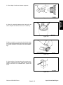
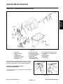
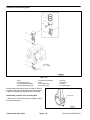
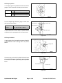
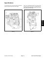
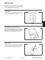
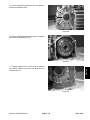
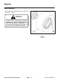
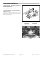
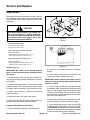
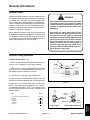
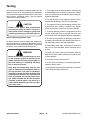
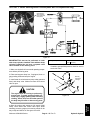
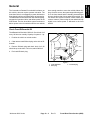
Jacking Vehicle
CAUTION
When changing attachments, tires or performing other service, use the correct blocks,
hoists and jacks. Always chock or block the
wheels and use jack stands or solid wood
blocks to support the machine. If the traction
unit is not properly supported by blocks or
jack stands, the unit may move or fall resulting in personal injury.
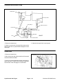
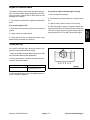
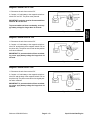
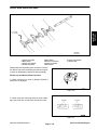
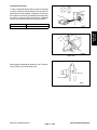
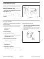
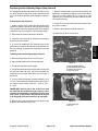
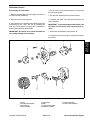
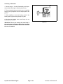
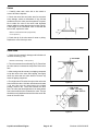
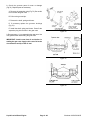
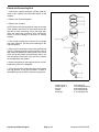
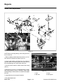
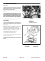
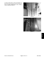
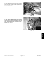
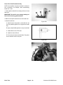
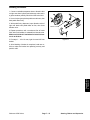
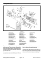
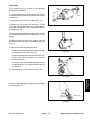
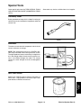
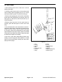
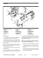
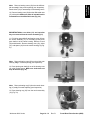
1
Figure 1
1. Front jacking point
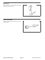
1. Do not start engine while vehicle is on jack, because
engine vibration or wheel movement could cause vehicle to slip off jack.
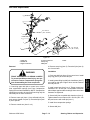
1
2. Do not work under vehicle without jack stands supporting it. The vehicle could slip off jack, injuring any one
beneath it.
1
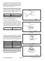
Figure 2
1. Rear jacking points
3. The jacking point at the front of the vehicle is under
the front center frame support and at the rear it is under
the axle tube.
4. When jacking up front of vehicle, always place a 2x4
block (or similar material) between jack and vehicle
frame.
Safety
Page 1 – 4
Rev. C
Workman 3000 Series
Safety
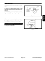
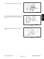
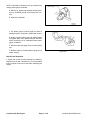
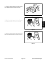
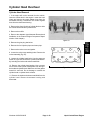
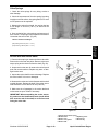
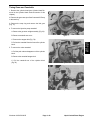
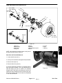
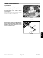
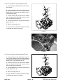
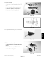
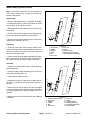
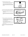
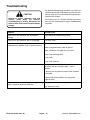
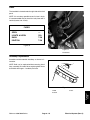
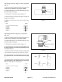
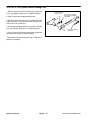
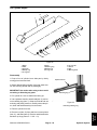
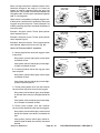
Using Bed Safety Support
Many of the procedures shown in this manual require raising and lowering the bed. The following
precautions must be taken or serious injury or
death could result.
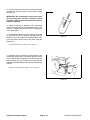
1
WARNING
Before servicing or making adjustments to
the machine, stop engine, set parking brake
and remove key from ignition switch. Any
load material must be removed from bed or
other attachment before working under
raised bed. Never work under a raised bed
without positioning safety support on a fully
installed cylinder rod.
2
After work is completed, remove safety support,
slide it onto storage stud and lower bed.
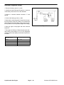
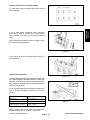
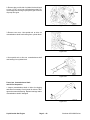
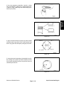
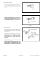
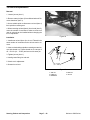
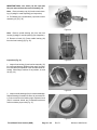
Figure 3
1. Bed support
2. Storage stud
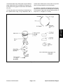
1. Raise bed until lift cylinders are fully extended.
2. Remove bed support from storage stud on top of back
rest support channel on Workman (Fig. 3).
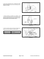
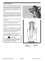
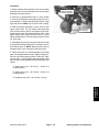
3. Push bed support onto cylinder rod, making sure support end tabs rest on end of cylinder barrel and on cylinder rod end (Fig. 4).
1
4. To store bed support, remove bed support from cylinder and insert on stud on top of back rest support channel.
3
5. Always install or remove bed support from outside of
bed.
6. Do not try to lower bed with bed safety support on cylinder.
2
Figure 4
1. Bed support
2. Cylinder barrel
3. Bed
Workman 3000 Series
Page 1 – 5
Safety
Safety
Page 1 – 6
Workman 3000 Series
Chapter 2
Table of Contents
1
2
2
2
TORQUE SPECIFICATIONS . . . . . . . . . . . . . . . . . . . 3
Capscrew Markings and Torque Values – U.S. . . 3
Capscrew Markings and Torque Values – Metric . 3
LUBRICATION . . . . . . . . . . . . . . . . . . . . . . . . . . . . . . . . 7
QUICK REFERENCE MAINTENANCE AID . . . . . . . 9
OPERATION AND SERVICE HISTORY REPORT . 11
Record information about your Workman vehicle on the
OPERATION AND SERVICE HISTORY REPORT form.
Use this information when referring to your machine.
Insert Operator’s Manuals and Parts Catalogs for your
Workman vehicle at the end of this section.
PRODUCT RECORDS . . . . . . . . . . . . . . . . . . . . . . . . .
EQUIVALENTS AND CONVERSIONS . . . . . . . . . . .
Decimal and Millimeter Equivalents . . . . . . . . . . . .
U.S. to Metric Conversions . . . . . . . . . . . . . . . . . . .
Product Records
Workman 3000/4000 Series
Page 2 – 1 Rev. D
Product Records and Maintenance
Product Records
and Maintenance
Product Records and Maintenance
Equivalents and Conversions
Product Records and Maintenance
Page 2 – 2
Workman 3000/4000 Series
Recommended fastener torque values are listed in the
following tables. For critical applications, as determined
by Toro, either the recommended torque or a torque that
is unique to the application is clearly identified and specified in this Service Manual.
These Torque Specifications for the installation and
tightening of fasteners shall apply to all fasteners which
do not have a specific requirement identified in this Service Manual. The following factors shall be considered
when applying torque: cleanliness of the fastener, use
of a thread sealant (Loctite), degree of lubrication on the
fastener, presence of a prevailing torque feature, hardness of the surface underneath the fastener’s head, or
similar condition which affects the installation.
As noted in the following tables, torque values should be
reduced by 25% for lubricated fasteners to achieve
the similar stress as a dry fastener. Torque values may
also have to be reduced when the fastener is threaded
into aluminum or brass. The specific torque value
should be determined based on the aluminum or brass
material strength, fastener size, length of thread engagement, etc.
The standard method of verifying torque shall be performed by marking a line on the fastener (head or nut)
and mating part, then back off fastener 1/4 of a turn.
Measure the torque required to tighten the fastener until
the lines match up.
Fastener Identification
Grade 1
Grade 5
Grade 8
Class 8.8
Inch Series Bolts and Screws
Workman 3000/4000 Series
Class 10.9
Metric Bolts and Screws
Page 2 – 3 Rev. D
Product Records and Maintenance
Product Records
and Maintenance
Torque Specifications
Standard Torque for Dry, Zinc Plated, and Steel Fasteners (Inch Series)
Thread Size
Grade 1, 5, &
8 with Thin
Height Nuts
SAE Grade 1 Bolts, Screws, Studs, &
Sems with Regular Height Nuts
(SAE J995 Grade 2 or Stronger Nuts)
in–lb
in–lb
N–cm
10 + 2
13 + 2
147 + 23
# 6 – 32 UNC
# 6 – 40 UNF
# 8 – 32 UNC
13 + 2
25 + 5
# 10 – 24 UNC
30 + 5
SAE Grade 8 Bolts, Screws, Studs, &
Sems with Regular Height Nuts
(SAE J995 Grade 5 or Stronger Nuts)
in–lb
N–cm
in–lb
N–cm
15 + 2
170 + 20
23 + 2
260 + 20
17 + 2
190 + 20
25 + 2
280 + 20
29 + 3
330 + 30
41 + 4
460 + 45
31 + 3
350 + 30
43 + 4
485 + 45
42 + 4
475 + 45
60 + 6
675 + 70
48 + 4
540 + 45
68 + 6
765 + 70
282 + 30
# 8 – 36 UNF
18 + 2
SAE Grade 5 Bolts, Screws, Studs, &
Sems with Regular Height Nuts
(SAE J995 Grade 2 or Stronger Nuts)
339 + 56
# 10 – 32 UNF
1/4 – 20 UNC
48 + 7
53 + 7
599 + 79
100 + 10
1125 + 100
140 + 15
1580 + 170
1/4 – 28 UNF
53 + 7
65 + 10
734 + 113
115 + 10
1300 + 100
160 + 15
1800 + 170
5/16 – 18 UNC
115 + 15
105 + 17
1186 + 169
200 + 25
2250 + 280
300 + 30
3390 + 340
5/16 – 24 UNF
138 + 17
128 + 17
1446 + 192
225 + 25
2540 + 280
325 + 30
3670 + 340
ft–lb
ft–lb
N–m
ft–lb
N–m
ft–lb
N–m
3/8 – 16 UNC
16 + 2
16 + 2
22 + 3
30 + 3
41 + 4
43 + 4
58 + 5
3/8 – 24 UNF
17 + 2
18 + 2
24 + 3
35 + 3
47 + 4
50 + 4
68 + 5
7/16 – 14 UNC
27 + 3
27 + 3
37 + 4
50 + 5
68 + 7
70 + 7
95 + 9
7/16 – 20 UNF
29 + 3
29 + 3
39 + 4
55 + 5
75 + 7
77 + 7
104 + 9
1/2 – 13 UNC
30 + 3
48 + 7
65 + 9
75 + 8
102 + 11
105 + 10
142 + 14
1/2 – 20 UNF
32 + 3
53 + 7
72 + 9
85 + 8
115 + 11
120 + 10
163 + 14
5/8 – 11 UNC
65 + 10
88 + 12
119 + 16
150 + 15
203 + 20
210 + 20
285 + 27
5/8 – 18 UNF
75 + 10
95 + 15
129 + 20
170 + 15
230 + 20
240 + 20
325 + 27
3/4 – 10 UNC
93 + 12
140 + 20
190 + 27
265 + 25
359 + 34
375 + 35
508 + 47
3/4 – 16 UNF
115 + 15
165 + 25
224 + 34
300 + 25
407 + 34
420 + 35
569 + 47
7/8 – 9 UNC
140 + 20
225 + 25
305 + 34
430 + 45
583 + 61
600 + 60
813 + 81
7/8 – 14 UNF
155 + 25
260 + 30
353 + 41
475 + 45
644 + 61
660 + 60
895 + 81
Note: Reduce torque values listed in the table above
by 25% for lubricated fasteners. Lubricated fasteners
are defined as threads coated with a lubricant such as
oil, graphite, or thread sealant such as Loctite.
Note: Torque values may have to be reduced when
installing fasteners into threaded aluminum or brass.
The specific torque value should be determined based
Product Records and Maintenance
on the fastener size, the aluminum or base material
strength, length of thread engagement, etc.
Note: The nominal torque values listed above for
Grade 5 and 8 fasteners are based on 75% of the minimum proof load specified in SAE J429. The tolerance is
approximately + 10% of the nominal torque value. Thin
height nuts include jam nuts.
Page 2 – 4 Rev. D
Workman 3000/4000 Series
Standard Torque for Dry, Zinc Plated, and Steel Fasteners (Metric Fasteners)
Class 8.8 Bolts, Screws, and Studs with
Reg lar Height N
ts
Regular
Nuts
(Class 8 or Stronger Nuts)
Class 10.9 Bolts, Screws, and Studs with
Reg lar Height N
ts
Regular
Nuts
(Class 10 or Stronger Nuts)
M5 X 0.8
57 + 5 in–lb
640 + 60 N–cm
78 + 7 in–lb
885 + 80 N–cm
M6 X 1.0
96 + 9 in–lb
1018 + 100 N–cm
133 + 13 in–lb
1500 + 150 N–cm
M8 X 1.25
19 + 2 ft–lb
26 + 3 N–m
27 + 2 ft–lb
36 + 3 N–m
M10 X 1.5
38 + 4 ft–lb
52 + 5 N–m
53 + 5 ft–lb
72 + 7 N–m
M12 X 1.75
66 + 7 ft–lb
90 + 10 N–m
92 + 9 ft–lb
125 + 12 N–m
M16 X 2.0
166 + 15 ft–lb
225 + 20 N–m
229 + 22 ft–lb
310 + 30 N–m
M20 X 2.5
325 + 33 ft–lb
440 + 45 N–m
450 + 37 ft–lb
610 + 50 N–m
Note: Reduce torque values listed in the table above
by 25% for lubricated fasteners. Lubricated fasteners
are defined as threads coated with a lubricant such as
oil, graphite, or thread sealant such as Loctite.
Note: Torque values may have to be reduced when
installing fasteners into threaded aluminum or brass.
The specific torque value should be determined based
Workman 3000/4000 Series
on the fastener size, the aluminum or base material
strength, length of thread engagement, etc.
Note: The nominal torque values listed above are
based on 75% of the minimum proof load specified in
SAE J1199. The tolerance is approximately + 10% of the
nominal torque value.
Page 2 – 5 Rev. D
Product Records and Maintenance
Product Records
and Maintenance
Thread Size
Other Torque Specifications
SAE Grade 8 Steel Set Screws
Wheel Bolts and Lug Nuts
Recommended Torque
Thread Size
Recommended Torque**
Thread Size
Square Head
Hex Socket
1/4 – 20 UNC
140 + 20 in–lb
73 + 12 in–lb
5/16 – 18 UNC
215 + 35 in–lb
145 + 20 in–lb
3/8 – 16 UNC
35 + 10 ft–lb
18 + 3 ft–lb
1/2 – 13 UNC
75 + 15 ft–lb
50 + 10 ft–lb
7/16 – 20 UNF
Grade 5
65 + 10 ft–lb
88 + 14 N–m
1/2 – 20 UNF
Grade 5
80 + 10 ft–lb
108 + 14 N–m
M12 X 1.25
Class 8.8
80 + 10 ft–lb
108 + 14 N–m
M12 X 1.5
Class 8.8
80 + 10 ft–lb
108 + 14 N–m
** For steel wheels and non–lubricated fasteners.
Thread Cutting Screws
(Zinc Plated Steel)
Thread Cutting Screws
(Zinc Plated Steel)
Type 1, Type 23, or Type F
Thread
Size
Threads per Inch
Baseline Torque*
Torq e*
Type A
Type B
No. 6
18
20
20 + 5 in–lb
30 + 5 in–lb
No. 8
15
18
30 + 5 in–lb
No. 10 – 24 UNC
38 + 7 in–lb
No. 10
12
16
38 + 7 in–lb
1/4 – 20 UNC
85 + 15 in–lb
No. 12
11
14
85 + 15 in–lb
5/16 – 18 UNC
110 + 20 in–lb
3/8 – 16 UNC
200 + 100 in–lb
Thread Size
Baseline Torque*
No. 6 – 32 UNC
20 + 5 in–lb
No. 8 – 32 UNC
* Hole size, material strength, material thickness & finish
must be considered when determining specific torque
values. All torque values are based on non–lubricated
fasteners.
Conversion Factors
in–lb X 11.2985 = N–cm
ft–lb X 1.3558 = N–m
Product Records and Maintenance
N–cm X 0.08851 = in–lb
N–m X 0.7376 = ft–lb
Page 2 – 6 Rev. D
Workman 3000/4000 Series
Lubrication
WARNING
Product Records
and Maintenance
Before servicing or making adjustments to
the machine, stop engine, set parking brake,
and remove key from the ignition switch.
Any load material must be removed from the
bed or other attachment before working under it. Always place the safety support on an
extended lift cylinder to hold up the bed.
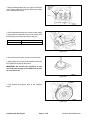
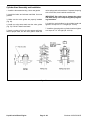
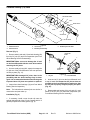
GREASING BEARINGS AND BUSHINGS
The vehicle has grease fittings that must be lubricated
regularly with No. 2 General Purpose Lithium Base
Grease. If the machine is operated under normal conditions, lubricate all bearings and bushings after every
100 hours of operation. More frequent lubrication is required if the vehicle is used for heavy duty operations.
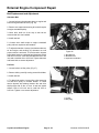
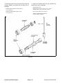
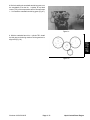
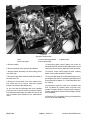
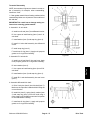
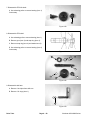
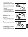
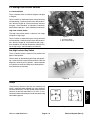
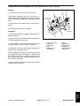
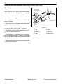
Figure 1
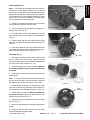
The grease fitting locations and quantities are as follows:
A. Two on each tie rod end and two on each front
ball joint (Fig. 1).
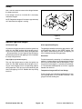
B. Nine on each rear drive shaft (Fig. 2).
C. One on each control arm tower, which can be accessed from under each front fender and the skirt
assembly (Fig. 3).
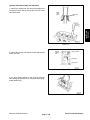
D. One on each pedal pivot and one on the accelerator bell crank (Fig. 4).
Figure 2
E. One on the steering shaft (Fig. 5).
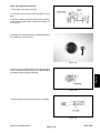
F. Three on the front drive shaft (4WD vehicles
only) (Fig. 6).
G. One on the accelerator bellcrank (liquid cooled
diesel engines only) (Fig. 7).
H. One on the governor lever (liquid cooled gasoline engines only) (Fig. 8).
IMPORTANT: When greasing the drive shaft universal
shaft bearing crosses, pump grease until it comes out of
all 4 cups at each cross.
1. Wipe grease fitting clean so that foreign matter cannot be forced into the bearing or bushing.
Figure 3
2. Pump grease into the bearing or bushing.
3. Wipe off excess grease.
Workman 3000/4000 Series
Page 2 – 7 Rev. B
Product Records and Maintenance
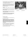
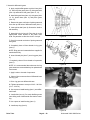
Figure 6
Figure 4
Figure 7
Figure 5
Figure 8
IMPORTANT
Heavy Duty Operation
If vehicle is subjected to conditions listed below, maintenance should be performed twice as frequently.
D Desert operation
D Cold climate operation (below 32_F)
D Trailer or 5th wheel towing
D Frequent operation on dusty roads
D Frequent operation under maximum vehicle gross weight
D Construction work
D As soon as possible after extended operation in mud, sand, water, or similar dirty conditions: inspect
and clean brakes, and grease drive axle joints. This will prevent any abrasive material from causing excessive wear.
D Under frequent heavy duty operating conditions, lubricate all grease fittings and inspect air cleaner
daily to prevent excessive wear.
Product Records and Maintenance
Page 2 – 8
Workman 3000/4000 Series
Product Records
and Maintenance
15
SAE 10W–30
SG, SH or SJ
15
SAE 10W–30
SG, SH or SJ
DEXTRON III ATF
93–2195
NOTE: Two wheel drive chart shown.
Workman 3000/4000 Series
Page 2 – 9 Rev. D
Product Records and Maintenance
15
See Note Below
NOTE: Four wheel drive chart shown. Use SAE 10W–30 CD, CE, CF, or CF–4 engine oil.
Product Records and Maintenance
Page 2 – 10 Rev. D
Workman 3000/4000 Series
Product Records
and Maintenance
EQUIPMENT OPERATION AND SERVICE HISTORY REPORT
FOR
WORKMANr 3100 AND 3120 VEHICLES
TORO Model and Serial Number: _____________–___________
Engine Numbers:
_________________________
Transaxle Numbers: _________________________
Date Purchased:
_________________________
Purchased From:
_________________________
Warranty Expires___________
_________________________
_________________________
Contacts:
Parts
_________________________
Phone___________________
Service
_________________________
Phone___________________
Sales
_________________________
Phone___________________
See your TORO Distributor for other Publications, Manuals, and Videos from the TORO company.
Workman 3000/4000 Series
Page 2 – 11 Rev. D
Product Records and Maintenance
WORKMANr 3100 and 3120 Maintenance Schedule
Minimum Recommended Maintenance Intervals:
Maintenance Procedure
Maintenance Interval & Service
Every
50hrs
Check Battery Fluid Level
Check Battery Cable Connections
Lubricate Engine Prefilter
Every
100hrs
Every
200hrs
Every
400hrs
Every
800hrs
A Level
Service
{ Change Engine Oil and Filter
Lubricate All Grease Fittings
Remove Engine Shrouds and Clean Fins
Inspect Condition and Wear of Tires
B Level
Service
} Check Cable Adjustments
} Check Pump Drive Belt Tension
Replace Air Filter
Check Engine RPM (Idle and Full Throttle)
C Level
Service
} Torque Wheel Lug Nuts
Check Front Wheel Alignment
Inspect Service and Parking Brakes
Inspect Fuel Lines
Replace Fuel Filter
D Level
Service
} Replace Transaxle Filter
Change Transaxle Oil
Clean Transaxle Strainer
Pack Front Wheel Bearings
Replace Spark Plugs
E Level
Service
{ Initial break in at 5 hours
} Initial break in at 10 hours
Replace all Interlock Switches
Drain/Flush Fuel Tank
Change Brake Fluid
Annual Recommendations:
Items listed are recommended every 1200
hours or 2 years, whichever occurs first.
(See Operator’s and Service Manual for specifications an procedures)
Product Records and Maintenance
Page 2 – 12 Rev. D
Workman 3000/4000 Series
WORKMANr 3100 and 3120 Daily Maintenance Check List
Unit Designation:_____________
TORO ID#________–_________
Daily Maintenance Check For Week Of _________________
Maintenance
Check Item b
MON
TUES
WED
THURS
FRI
SAT
SUN
____Hrs. ____Hrs. ____Hrs. ____Hrs. ____Hrs. ____Hrs. ____Hrs.
n
Safety Interlock Operation
n
Service & Park Brake
Operation
n
Clutch & Shifter Operation
n
Fuel Level
n
Engine Oil Level
n
Transaxle Oil Level
n
Brake Fluid Level
n
Air Filter Prefilter
Inspect Engine Cooling Fins
n
Unusual Engine Noises
n
Unusual Operating Noises
n
Tire Pressure
n
Hydraulic Hoses for Damage
n
Fluid Leaks
n
Instrument Operation
n
Accelerator Operation
Lubricate All Grease Fittings1
Touch–up Damaged Paint
1=
Immediately after every washing, regardless of the interval listed.
Notation for areas of concern:
Item
Date
Information
Inspection performed by___________________________
1
2
3
4
5
6
7
8
(See Operator’s and Service Manual for specifications an procedures)
Workman 3000/4000 Series
Page 2 – 13 Rev. D
Product Records and Maintenance
Product Records
and Maintenance
Daily Maintenance: (duplicate this page for routine use)
Product Records and Maintenance
Page 2 – 14 Rev. D
Workman 3000/4000 Series
A B C D Other
Service to perform (circle):
__________________–__________________
TORO I.D. #:
_______________________________
_______________________________
_______________________________
________________________________
________________________________
________________________________
Change Transaxle Oil
Clean Transaxle Strainer
Pack Front Wheel Bearings
Replace Spark Plugs
A, B, C, and D – Service Required
_______________________________
_______________________________
_______________________________
Inspect Service and Parking Brakes
Inspect Fuel Lines
Replace Fuel Filter
A, B, and C – Sevice required
________________________________
________________________________
________________________________
________________________________
(See Operator’s and Service Manual for specifications and procedures.)
Replace Transaxle Filter
Check Front Wheel Alignment
E – Service (every 800 hours)
_______________________________
________________________________
D – Service (every 400 hours)
_______________________________
________________________________
Inspect Condition and Wear of Tires
Lubricate Engine Prefilter
A – Service required
Remove Engine Shrouds & Clean Fins
Check Battery Cable Connections
Change Engine Oil and Filter
Lubricate All Grease Fittings
B – Service (every 100 hours)
Remarks:
Check Battery Fluid Levels
A– Service (every 50 hours)
Technician:
Hours:
Unit Designation:
(Duplicate this page for routine use.)
WORKMAN R 3100 and 3120 Supervisor Maintenance Order
Form No. 95–852–SL
_______________________________
_______________________________
_______________________________
_______________________________
_______________________________
_______________________________
Change Brake Fluid
Drain/Flush Fuel Tank
Replace All Interlock Switches
Other – Annual Service and Specials
________________________________
________________________________
________________________________
A and B – Sevice required
Torque Wheel Lug Nuts
Check Engine RPM (Idle & Full Throttle)
Replace Air Filter
Check Pump Drive Belt Tension
Check Cable Adjustments
C – Service (every 200 hours)
Date: ________________
Product Records
and Maintenance
EQUIPMENT OPERATION AND SERVICE HISTORY REPORT
FOR
WORKMANr 3200, 3210, 3220, AND 4200 VEHICLES
TORO Model and Serial Number: _____________–___________
Engine Numbers:
_________________________
Transaxle/Differential Numbers:
_________________________
Date Purchased:
_________________________
Purchased From:
_________________________
Warranty Expires___________
_________________________
_________________________
Contacts:
Parts
_________________________
Phone___________________
Service
_________________________
Phone___________________
Sales
_________________________
Phone___________________
See your TORO Distributor for other Publications, Manuals, and Videos from the TORO company.
Workman 3000/4000 Series
Page 2 – 15 Rev. D
Product Records and Maintenance
WORKMANr 3200, 3210, 3220, and 4200 Maintenance Schedule
Minimum Recommended Maintenance Intervals
Maintenance Procedure
Maintenance Interval & Service
Check Battery Fluid Level
Check Battery Cable Connections
Check Dust Cup and Baffle
Every
50hrs
A Level
Service
Every
100hrs
Every
200hrs
Every
400hrs
Every
800hrs
Lubricate All Grease Fittings
Inspect Condition and Wear of Tires
Check Front Differential Oil Level (4WD)
} Change Engine Oil and Filter
Inspect Cooling System Hoses
Check Governor Oil Level
B Level
Service
{ Check Cable Adjustments
Check Alternator, Governor and Fan Belts
Change Air Cleaner Filter
Check Front Axle CV Boot Joint (4WD)
Check Engine RPM (Idle and Full Throttle)
C Level
Service
{ Torque Wheel Lug Nuts
Check Front Wheel Alignment
Inspect Service and Parking Brakes
Inspect Fuel Lines
Replace Fuel Filter
Adjust Valves
Replace Spark Plugs and Check Timing
D Level
Service
{ Replace Transaxle Filter
Change Transaxle Oil
Clean Transaxle Strainer
Pack Front Wheel Bearings (2WD)
Change Front Differential Oil (4WD)
E Level
Service
{ Initial break in at 10 hours
} Initial break in at 50 hours
Replace all Interlock Switches
Flush/Replace Coolant System Fluid
Change Brake Fluid
Replace Engine Timing Belt
Annual Recommendations:
Replace switches, Coolant and Brake Fluid every
1200 hours or 2 years, whichever occurs first.
Replace Engine Timing Belt every 2000 hours or 2
years, whichever occurs first.
(See Operator’s and Service Manual for specifications an procedures)
Product Records and Maintenance
Page 2 – 16
Rev. D
Workman 3000/4000 Series
WORKMANr 3200, 3210, 3220, and 4200 Daily Maintenance Checklist
Daily Maintenance Check For Week Of _________________
Maintenance
Check Item b
MON
TUES
WED
THURS
FRI
SAT
SUN
____Hrs. ____Hrs. ____Hrs. ____Hrs. ____Hrs. ____Hrs. ____Hrs.
n
Safety Interlock Operation
n
Service & Park Brake
Operation
n
Fuel Level
n
Accelerator Operation
n
Clutch & Shifter Operation
n
Engine Oil Level
n
Transaxle Oil Level
n
Cooling System Fluid Level1
n
Brake Fluid Level
n
Air Cleaner2
n
Unusual Engine Noises
n
Unusual Operating Noises
n
Tire Pressure
n
Radiator Screen/Clean out
Door2
n
Hydraulic Hoses for Damage
n
Fluid Leaks
n
Instrument Operation
Lubricate All Grease Fittings3
Touch–up Damaged Paint
1=
2=
3=
Inspect at Overflow Tank
More often when conditions are dirty
Immediately after every washing, regardless of the interval listed.
Notation for areas of concern:
Date
Information
Item
Inspection performed by_____________________________
1
2
3
4
5
6
7
8
(See Operator’s and Service Manual for specifications an procedures)
Workman 3000/4000 Series
Page 2 – 17 Rev. D
Product Records and Maintenance
Product Records
and Maintenance
Daily Maintenance: (duplicate this page for routine use)
Unit Designation:_____________
TORO ID#________–_________
Product Records and Maintenance
Page 2 – 18
Rev. D
Workman 3000/4000 Series
A B C D Other
Service to perform (circle):
__________________–__________________
TORO I.D. #:
A – Service required
_______________________________
_______________________________
________________________________
________________________________
________________________________
Change Transaxle Oil
Clean Transaxle Strainer
Pack Front Wheel Bearings (2WD)
Change Front Differential Oil (4WD)
A, B, C, and D – Service Required
_______________________________
_______________________________
_______________________________
Inspect Service and Parking Brakes
Inspect Fuel Lines
Replace Fuel Filter
Adjust Valves
Replace Spark Plugs and Check Timing
A, B, and C – Sevice required
________________________________
________________________________
(See Operator’s and Service Manual for specifications and procedures.)
Replace Transaxle Filter
Check Front Wheel Alignment
E – Service (every 800 hours)
Check Governor Oil Level
________________________________
D – Service (every 400 hours)
Inspect Cooling System Hoses
________________________________
Check Front Differential Oil Level (4WD)
Check Dust Cup and Baffle
Change Engine Oil and Filter
Inspect Condition and Wear of Tires
Check Battery Cable Connections
________________________________
Lubricate All Grease Fittings
B – Service (every 100 hours)
Remarks:
Check Battery Fluid Level
A– Service (every 50 hours)
Technician:
Hours:
Unit Designation:
(Duplicate this page for routine use.)
WORKMAN R 3200, 3210, 3220, and 4200 Supervisor Work Order
Form No. 95–853–SL
_______________________________
_______________________________
_______________________________
_______________________________
_______________________________
Replace Engine Timing Belt
Change Brake Fluid
Flush/Replace Coolant System Fluid
Replace All Interlock Switches
Other – Annual Service and Specials
________________________________
________________________________
A and B – Sevice required
Torque Wheel Lug Nuts
Check Engine RPM (Idle & Full Throttle)
Check Front Axle CV Joint Boot (4WD)
Change Air Cleaner Filter
Check Alternator, Governor and Fan Belts
Check Cable Adjustments
C – Service (every 200 hours)
Date: ________________
Product Records
and Maintenance
EQUIPMENT OPERATION AND SERVICE HISTORY REPORT
FOR
WORKMANr 3300–D, 3310–D, 3320–D, AND 4300–D VEHICLES
TORO Model and Serial Number: _____________–___________
Engine Numbers:
_________________________
Transaxle/Differential Numbers:
_________________________
Date Purchased:
_________________________
Purchased From:
_________________________
Warranty Expires___________
_________________________
_________________________
Contacts:
Parts
_________________________
Phone___________________
Service
_________________________
Phone___________________
Sales
_________________________
Phone___________________
See your TORO Distributor for other Publications, Manuals, and Videos from the TORO company.
Workman 3000/4000 Series
Page 2 – 19 Rev. D
Product Records and Maintenance
WORKMANr 3300–D, 3310–D, 3320–D, and 4300–D Maintenance Schedule
Minimum Recommended Maintenance Intervals
Maintenance Procedure
Maintenance Interval & Service
Every
50hrs
A Level
Service
Check Battery Fluid Level
Check Battery Cable Connections
Check Dust Cup and Baffle
Every
100hrs
Every
200hrs
Every
400hrs
Every
800hrs
Lubricate All Grease Fittings
Inspect Condition and Wear of Tires
Check Front Differential Oil Level (4WD)
} Change Engine Oil and Filter
Inspect Cooling System Hoses
B Level
Service
{ Check Cable Adjustments
{ Check Alternator and Fan Belts
Service Air Filter
Check Front Axle CV Boot Joint (4WD)
Check Engine RPM (Idle and Full Throttle)
C Level
Service
{ Torque Wheel Lug Nuts
Check Front Wheel Alignment
Inspect Service and Parking Brakes
Inspect Fuel Lines
Replace Electric Fuel Pump Filter
Replace Fuel/Water Separator Filter
D Level
Service
} Torque Cylinder Head and Adjust Valves
{ Replace Transaxle Filter
Change Transaxle Oil
Clean Transaxle Strainer
Pack Front Wheel Bearings
Change Front Differential Oil (4WD)
E Level
Service
{ Initial break in at 10 hours
} Initial break in at 50 hours
Replace all Interlock Switches
Flush/Replace Coolant System Fluid
Change Brake Fluid
Drain/Flush Fuel Tank
Annual Recommendations:
Replace switches, Coolant and Brake Fluid every
1200 hours or 2 years, whichever occurs first.
(See Operator’s and Service Manual for specifications an procedures)
Product Records and Maintenance
Page 2 – 20
Rev. D
Workman 3000/4000 Series
WORKMANr 3300–D, 3310–D, 3320–D, and 4300–D Daily Maintenance Checklist
Daily Maintenance Check For Week Of _________________
Maintenance
Check Item b
MON
TUES
WED
THURS
FRI
SAT
SUN
____Hrs. ____Hrs. ____Hrs. ____Hrs. ____Hrs. ____Hrs. ____Hrs.
n
Safety Interlock Operation
n
Service & Park Brake
Operation
n
Fuel Level
n
Accelerator Operation
n
Clutch & Shifter Operation
n
Engine Oil Level
n
Transaxle Oil Level
n
Cooling System Fluid Level1
n
Brake Fluid Level
n
Air Cleaner2
n
Unusual Engine Noises
n
Unusual Operating Noises
n
Tire Pressure
n
Radiator Screen/Clean out
Door2
n
Hydraulic Hoses for Damage
n
Fluid Leaks
n
Instrument Operation
Lubricate All Grease Fittings3
Touch–up Damaged Paint
1=
2=
3=
Inspect at Overflow Tank
More often when conditions are dirty
Immediately after every washing, regardless of the interval listed.
Notation for areas of concern:
Item
Date
Inspection performed by_____________________________
Information
1
2
3
4
5
6
7
8
(See Operator’s and Service Manual for specifications an procedures)
Workman 3000/4000 Series
Page 2 – 21 Rev. D
Product Records and Maintenance
Product Records
and Maintenance
Daily Maintenance: (duplicate this page for routine use)
Unit Designation:_____________
TORO ID#________–_________
Product Records and Maintenance
Page 2 – 22
Rev. D
Workman 3000/4000 Series
R
A B C D Other
Service to perform (circle):
__________________–__________________
TORO I.D. #:
_______________________________
_______________________________
_______________________________
________________________________
________________________________
________________________________
Change Transaxle Oil
Clean Transaxle Strainer
Pack Front Wheel Bearings (2WD)
Change Front Differential Oil (4WD)
A, B, C, and D – Service Required
_______________________________
_______________________________
_______________________________
Inspect Service and Parking Brakes
Inspect Fuel Lines
Replace Electric Fuel Pump Filter
Replace Fuel/Water Separator Filter
Torque Cylinder Head and Adjust Valves
A, B, and C – Sevice required
________________________________
________________________________
(See Operator’s and Service Manual for specifications and procedures.)
Replace Transaxle Filter
Check Front Wheel Alignment
E – Service (every 800 hours)
A – Service required
________________________________
D – Service (every 400 hours)
Inspect Cooling System Hoses
________________________________
Check Front Differential Oil Level (4WD)
Check Dust Cup and Baffle
Change Engine Oil and Filter
Inspect Condition and Wear of Tires
Check Battery Cable Connections
________________________________
Lubricate All Grease Fittings
B – Service (every 100 hours)
Check Battery Fluid Level
A– Service (every 50 hours)
Technician:
Hours:
Unit Designation:
Remarks:
Date: ____________
Form No. 95–854–SL
_______________________________
_______________________________
_______________________________
_______________________________
_______________________________
Drain/Flush Fuel Tank
Change Brake Fluid
Flush/Replace Coolant System Fluid
Replace All Interlock Switches
Other – Annual Service and Specials
________________________________
________________________________
A and B – Sevice required
Torque Wheel Lug Nuts
Check Engine RPM (Idle & Full Throttle)
Check Front Axle CV Joint Boot (4WD)
Service Air Filter
Check Alternator, Governor and Fan Belts
Check Cable Adjustments
C – Service (every 200 hours)
3300–D, 3310–D, 3320–D, and 4300–D Supervisor Maintenance Order
(Duplicate this page for routine use.)
WORKMAN
Product Records
and Maintenance
EQUIPMENT OPERATION AND SERVICE HISTORY REPORT
for
WORKMANr 3420–LP VEHICLE
TORO Model and Serial Number: _____________–___________
Engine Numbers:
_________________________
Transaxle/Differential Numbers:
_________________________
Date Purchased:
_________________________
Purchased From:
_________________________
Warranty Expires___________
_________________________
_________________________
Contacts:
Parts
_________________________
Phone___________________
Service
_________________________
Phone___________________
Sales
_________________________
Phone___________________
See your TORO Distributor for other Publications, Manuals, and Videos from the TORO company.
Workman 3000/4000 Series
Page 2 – 23 Rev. D
Product Records and Maintenance
WORKMANr 3420–LP Maintenance Schedule
Minimum Recommended Maintenance Intervals
Maintenance Procedure
Maintenance Interval & Service
Every
50hrs
A Level
Service
Check Battery Fluid Level
Check Battery Cable Connections
Check Dust Cup and Baffle
Every
100hrs
Every
200hrs
Every
400hrs
Every
800hrs
Lubricate All Grease Fittings
Inspect Condition and Wear of Tires
} Change Engine Oil and Filter
Inspect Cooling System Hoses
Check Governor Oil Level
B Level
Service
{ Check Cable Adjustments
{ Check Alternator, Governor and Fan Belts
Change Air Cleaner Filter
Check Engine RPM (Idle and Full Throttle)
C Level
Service
{ Torque Wheel Lug Nuts
Check Front Wheel Alignment
Inspect Service and Parking Brakes
Inspect Fuel Lines
Replace Fuelock Filter
Adjust Valves
Replace Spark Plugs and Check Timing
D Level
Service
{ Replace Transaxle Filter
Change Transaxle Oil
Clean Transaxle Strainer
Pack Front Wheel Bearings
E Level
Service
{ Initial break in at 10 hours
} Initial break in at 50 hours
Replace all Interlock Switches
Flush/Replace Coolant System Fluid
Change Brake Fluid
Replace Engine Timing Belt
Annual Recommendations:
Replace switches, Coolant and Brake Fluid every
1200 hours or 2 years, whichever occurs first.
Replace Engine Timing Belt every 2000 hours or 2
years, whichever occurs first.
(See Operator’s and Service Manual for specifications an procedures)
Product Records and Maintenance
Page 2 – 24 Rev. D
Workman 3000/4000 Series
WORKMANr 3420–LP Daily Maintenance Checklist
Daily Maintenance Check For Week Of _________________
Maintenance
Check Item b
MON
TUES
WED
THURS
FRI
SAT
SUN
____Hrs. ____Hrs. ____Hrs. ____Hrs. ____Hrs. ____Hrs. ____Hrs.
n
Safety Interlock Operation
n
Service & Park Brake
Operation
n
Fuel Level
n
Accelerator Operation
n
Clutch & Shifter Operation
n
Engine Oil Level
n
Transaxle Oil Level
n
Cooling System Fluid Level1
n
Brake Fluid Level
n
Air Cleaner2
n
Unusual Engine Noises
n
Unusual Operating Noises
n
Tire Pressure
n
Radiator Screen/Clean out
Door2
n
Hydraulic Hoses for Damage
n
Fluid Leaks
n
Instrument Operation
Lubricate All Grease Fittings3
Touch–up Damaged Paint
1=
2=
3=
Inspect at Overflow Tank
More often when conditions are dirty
Immediately after every washing, regardless of the interval listed.
Notation for areas of concern:
Date
Information
Item
Inspection performed by_____________________________
1
2
3
4
5
6
7
8
(See Operator’s and Service Manual for specifications an procedures)
Workman 3000/4000 Series
Page 2 – 25 Rev. D
Product Records and Maintenance
Product Records
and Maintenance
Daily Maintenance: (duplicate this page for routine use)
Unit Designation:_____________
TORO ID#________–_________
Product Records and Maintenance
Page 2 – 26
Rev. D
Workman 3000/4000 Series
A B C D Other
Service to perform (circle):
__________________–__________________
TORO I.D. #:
_______________________________
_______________________________
________________________________
________________________________
________________________________
________________________________
Change Transaxle Oil
Clean Transaxle Strainer
Pack Front Wheel Bearings
A, B, C, and D – Service Required
_______________________________
_______________________________
_______________________________
_______________________________
Inspect Service and Parking Brakes
Inspect Fuel Lines
Replace Fuelock Filter
Adjust Valves
Replace Spark Plugs and Check Timing
A, B, and C – Sevice required
________________________________
________________________________
(See Operator’s and Service Manual for specifications and procedures.)
Replace Transaxle Filter
Check Front Wheel Alignment
E – Service (every 800 hours)
A – Service required
________________________________
D – Service (every 400 hours)
Check Governor Oil Level
________________________________
Change Engine Oil and Filter
Check Dust Cup and Baffle
Inspect Cooling System Hoses
Inspect Condition and Wear of Tires
Check Battery Cable Connections
________________________________
Lubricate All Grease Fittings
B – Service (every 100 hours)
Remarks:
Check Battery Fluid Level
A– Service (every 50 hours)
Technician:
Hours:
Unit Designation:
(Duplicate this page for routine use.)
WORKMAN R 3420–LP Supervisor Maintenance Work Order
Form No. 95–853–SL
_______________________________
_______________________________
_______________________________
_______________________________
_______________________________
Replace Engine Timing Belt
Change Brake Fluid
Flush/Replace Coolant System Fluid
Replace All Interlock Switches
Other – Annual Service and Specials
________________________________
________________________________
________________________________
A and B – Sevice required
Torque Wheel Lug Nuts
Check Engine RPM (Idle & Full Throttle)
Change Air Cleaner Filter
Check Alternator, Governor and Fan Belts
Check Cable Adjustments
C – Service (every 200 hours)
Date: ________________
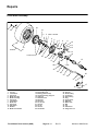
Chapter 3
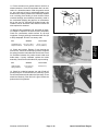
Mitsubishi Engine (Workman S/N Below 220000001)
Liquid Cooled Gas Engine
GENERAL INFORMATION . . . . . . . . . . . . . . . . . . . . . 2
SPECIFICATIONS . . . . . . . . . . . . . . . . . . . . . . . . . . . . 3
General . . . . . . . . . . . . . . . . . . . . . . . . . . . . . . . . . . . . 3
Engine . . . . . . . . . . . . . . . . . . . . . . . . . . . . . . . . . . . . . 4
Lubrication System . . . . . . . . . . . . . . . . . . . . . . . . . . 8
Fuel System . . . . . . . . . . . . . . . . . . . . . . . . . . . . . . . . 8
Cooling System . . . . . . . . . . . . . . . . . . . . . . . . . . . . . 8
Electrical System . . . . . . . . . . . . . . . . . . . . . . . . . . . . 9
Tightening Torque and Sealants / Adhesives . . . 10
SPECIAL TOOLS . . . . . . . . . . . . . . . . . . . . . . . . . . . . 12
INSPECTION AND ADJUSTMENTS . . . . . . . . . . . . 17
Valve Clearance . . . . . . . . . . . . . . . . . . . . . . . . . . . . 17
Timing Belt Tension . . . . . . . . . . . . . . . . . . . . . . . . . 19
Idle Speed . . . . . . . . . . . . . . . . . . . . . . . . . . . . . . . . . 20
Ignition Timing . . . . . . . . . . . . . . . . . . . . . . . . . . . . . 20
CO Concentration (Mixture Adjustment) . . . . . . . 21
Governor / Accelerator Pedal . . . . . . . . . . . . . . . . 22
Carburetor Acceleration Pump . . . . . . . . . . . . . . . 24
Choke Valve . . . . . . . . . . . . . . . . . . . . . . . . . . . . . . . 25
Full–Auto–Choke . . . . . . . . . . . . . . . . . . . . . . . . . . . 25
Choke Breaker Opening . . . . . . . . . . . . . . . . . . . . . 26
Fast Idle . . . . . . . . . . . . . . . . . . . . . . . . . . . . . . . . . . . 27
TROUBLESHOOTING . . . . . . . . . . . . . . . . . . . . . . . . 28
TESTING . . . . . . . . . . . . . . . . . . . . . . . . . . . . . . . . . . . 30
Temperature Gauge Sender . . . . . . . . . . . . . . . . . 31
Oil Pressure Switch . . . . . . . . . . . . . . . . . . . . . . . . . 31
Thermostat . . . . . . . . . . . . . . . . . . . . . . . . . . . . . . . . 31
Fuel Cut–Off Solenoid . . . . . . . . . . . . . . . . . . . . . . . 32
Compression Pressure . . . . . . . . . . . . . . . . . . . . . . 33
Intake Manifold Vacuum . . . . . . . . . . . . . . . . . . . . . 33
Centrifugal Timing Control Device . . . . . . . . . . . . 34
Vacuum Timing Control Device . . . . . . . . . . . . . . . 35
Crankcase Emission Control System . . . . . . . . . . 36
Exhaust Emission Control System . . . . . . . . . . . . 37
Thermo Valve . . . . . . . . . . . . . . . . . . . . . . . . . . . . . . 39
Ignition Coil . . . . . . . . . . . . . . . . . . . . . . . . . . . . . . . . 40
Starter Pinion Gap . . . . . . . . . . . . . . . . . . . . . . . . . . 41
Starter No–Load Test . . . . . . . . . . . . . . . . . . . . . . . 42
Magnetic Switch Pull–In Test . . . . . . . . . . . . . . . . . 43
Workman 3000/4000 Series
Magnetic Switch Hold–In Test . . . . . . . . . . . . . . . . 43
Magnetic Switch Return Test . . . . . . . . . . . . . . . . . 43
Alternator Regulated Voltage . . . . . . . . . . . . . . . . . 44
Alternator Output Current . . . . . . . . . . . . . . . . . . . . 45
PREPARATION FOR ENGINE REPAIR . . . . . . . . . 46
Cylinder and Cylinder Block Overhaul . . . . . . . . . 46
EXTERNAL ENGINE COMPONENT REPAIR . . . . 47
Belt Replacement and Adjustment . . . . . . . . . . . . 47
Timing Belt Replacement . . . . . . . . . . . . . . . . . . . . 48
Water Pump, Hose, Pipe and Thermostat
Removal and Installation . . . . . . . . . . . . . . . . . . . 55
Governor Removal and Installation . . . . . . . . . . . 57
ELECTRICAL SYSTEM REPAIRS . . . . . . . . . . . . . . 58
Spark Plug Replacement . . . . . . . . . . . . . . . . . . . . 58
Alternator Removal and Installation . . . . . . . . . . . 59
Alternator Service . . . . . . . . . . . . . . . . . . . . . . . . . . 60
Starter Removal and Installation . . . . . . . . . . . . . . 64
Starter Service . . . . . . . . . . . . . . . . . . . . . . . . . . . . . 65
Distributor Removal and Installation . . . . . . . . . . . 69
Distributor Service . . . . . . . . . . . . . . . . . . . . . . . . . . 70
FUEL SYSTEM REPAIRS . . . . . . . . . . . . . . . . . . . . . 72
Carburetor Removal and Installation . . . . . . . . . . 72
Carburetor Service . . . . . . . . . . . . . . . . . . . . . . . . . 73
REMOVING AND INSTALLING THE ENGINE . . . 79
Removing the Engine . . . . . . . . . . . . . . . . . . . . . . . 79
Installing the Engine . . . . . . . . . . . . . . . . . . . . . . . . 80
CYLINDER HEAD OVERHAUL . . . . . . . . . . . . . . . . 81
Intake and Exhaust Manifolds . . . . . . . . . . . . . . . . 81
Rocker Arm, Rocker Shaft and Camshaft . . . . . . 82
Rocker Arm and Rocker Shaft . . . . . . . . . . . . . . . . 85
Cylinder Head and Valves . . . . . . . . . . . . . . . . . . . 86
CYLINDER BLOCK OVERHAUL . . . . . . . . . . . . . . . 91
Front Case, Counterbalance Shaft and Oil Pan . 91
Piston and Connecting Rod . . . . . . . . . . . . . . . . . . 96
Oil Pump . . . . . . . . . . . . . . . . . . . . . . . . . . . . . . . . . 101
Crankshaft and Flywheel . . . . . . . . . . . . . . . . . . . 104
Cylinder Block . . . . . . . . . . . . . . . . . . . . . . . . . . . . 109
LUBRICATION SYSTEM REPAIR . . . . . . . . . . . . . . 111
Oil Screen, Dipstick and Oil Filter . . . . . . . . . . . . . 111
Page 3 – 1
Rev. E
Liquid Cooled Gas Engine
Liquid Cooled
Gas Engine
Table of Contents
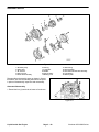
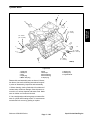
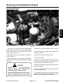
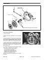
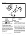
General Information
Most repairs and adjustments require tools which are
commonly available in many service shops. Special
tools are described in the Special Tools section. The use
of some specialized test equipment is explained, however, the cost of the test equipment and the specialized
nature of some repairs may dictate that the work be
done at a engine repair facility. If no parts list is available
be sure to provide your Distributor with the TORO Model
Number and Serial Number.
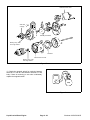
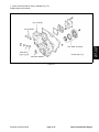
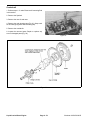
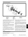
The engine model and serial number is stamped on the
left side of the cylinder block.
3G83
AA0201
Serial Number System:
AA0201
AB0001
BA0001
Engine Model Number
Engine Serial Number
AA9999
AY9999
YY9999
The engine used in the Workman 3200 is manufactured
by Mitsubishi Motors. Service and repair parts for Mitsubishi engines are supplied through TORO Distributors.
Repair parts may be ordered by TORO Part Number
Liquid Cooled Gas Engine
Page 3 – 2
Workman 3000/4000 Series
Specifications
General
Item
Specification
Make/Designation
Mitsubishi 3G83–051TV,
In–line slant (60_), over head camshaft
3
Cylinder Bore
65 mm (2.559 in.)
Piston Stroke
66 mm (2.598 in.)
Total Displacement
657 cc (40.09 cu. in.)
Compression Ratio
9.8:1
Firing Order
1–3–2
Fuel
Unleaded gasoline
Minimum Octane rating 87
Valve Timing
Intake Valve
Opens (BTDC) 15_
Closes (ABDC) 45_
Opens (BBTC) 45_
Closes (ATDC) 15_
Exhaust Valve
Coolant
50/50 Ethylene Glycol / Water
Cooling System Capacity
3.3 liter (3.5 qt.)
Engine Oil
10_ C to 40_ C (14_ F to 104_ F)
API SG or SG/CD
SAE 10W–30
Crankcase Oil Capacity
2.8 liter (3 qt.) with filter
Starter
Solenoid shift type
1.6 kW (12 volt)
Alternator
AC type 12 volt 40A
Spark Plug
Champion RN 16Y or NGK BPR 4ES
1.0 mm (.040 in.) air gap
High Idle (no load)
3600 RPM + 50 rpm
Idle Speed (no load)
Workman 3000/4000 Series
1200 RPM + 100 rpm
Page 3 – 3
Liquid Cooled Gas Engine
Liquid Cooled
Gas Engine
Number of Cylinders
Engine
Item
Standard Specification
Limit
Compression kPa (psi)
Minimum 960 (137)
Compression pressure
difference between cylinders kPa (psi)
Maximum 100 (14)
Cylinder Head
Overall height mm (in.)
Flatness of gasket surface mm (in.)
Oversize rework
of valve seat hole mm (in.)
Intake
0.3 (.012) oversize
0.6 (.024) oversize
Exhaust
0.3 (.012) oversize
0.6 (.024) oversize
Oversize rework of valve guide hole
(both intake and exhaust) mm (in.)
0.05 (.002) oversize
0.25 (.010) oversize
0.50 (.020) oversize
108.9 – 109.1 (4.287 – 4.295)
Less than 0.05 (.0019)
0.2 ( .008) see NOTE *
0.2 (.008)
31.300 – 31.325
(1.2323 – 1.2333)
31.600 – 31.625
(1.2441 – 1.2451)
29.300 – 29.321
(1.1535 – 1.1544)
29.600 – 29.621
(1.1653 – 1.1662)
12.050 – 12.068
(.4744 – .4751)
12.250 – 12.268
(.4823 – .4830)
12.500 – 12.518
(.4921 – .4928)
Camshaft
Cam height mm (in.)
Intake
No. 1
No. 2
No. 3
Exhaust
No. 1
No. 2
No. 3
Journal O.D. mm (in.)
Bearing oil clearance mm (in.)
End play mm (in.)
35.09 (1.3815)
35.07 (1.3807)
35.06 (1.3303)
34.59 (1.3618)
34.57 (1.3610)
34.56 (1.3606)
35.15 (1.3839)
35.13 (1.3831)
35.19 (1.3854)
34.65 (1.3642)
34.63 (1.3634)
34.69 (1.3657)
40.940 – 40.955
(1.6118 – 1.6124)
0.045 – 0.085
(.0018 – .0033)
0.06 – 0.14
(.0024 – .0055)
Rocker Arm
Clearance (rocker arm to shaft) mm (in.)
0.012 – 0.043
(.0005 – .0017)
0.1 (.004)
Rocker Shaft
O.D. mm (in.)
Length mm (in.)
16.985 – 16.998
(.6687 – .6692)
232.0 (9.134)
* NOTE: Limit must be combined with amount of grinding of cylinder block gasket surface.
NOTE: O.D. = Outside Diameter
Liquid Cooled Gas Engine
Page 3 – 4
Workman 3000/4000 Series
Engine (cont.)
Item
Standard Specification
Limit
Valves
Exhaust
Face angle
Thickness of valve head (margin) mm (in.)
Intake
Exhaust
100.6 (3.960)
100.8 (3.968)
6.565 – 6.580
(.2585 – .2591)
6.530 – 6.550
(.2571 – .2579)
45_ – 45.5_
1.0 (.039)
1.3 (.051)
0.5 (.020)
0.8 (.031)
Valve Stem to Guide Clearance mm (in.)
Intake
Exhaust
0.02 – 0.05
(.0008 – .0020)
0.050 – 0.085
(.0020 – .0033)
0.10 (.0039)
0.15 (.0059)
Valve Guides
Length mm (in.)
Intake
Exhaust
Service size mm (in.)
44 (1.73)
49.5 (1.949)
0.25 (.010)
0.50 (.020) oversize
Valve Seat
Width of seat contact mm (in.)
Seat angle
Sink mm (in.)
0.9 – 1.3 (.035 – .051)
30_ / 44_ / 65_
0.2 (.008)
Valve Spring
Free length mm (in.)
Load / installed height N/mm (lb./in.)
Out of squareness
46.3 (1.823)
210 / 37.7 (46 / 1.48)
Less than 2_
45.3 (1.783)
4_
Cylinder Block
Cylinder bore mm (in.)
Out of roundness and
taper of cylinder bore mm (in.)
Flatness of gasket surface mm (in.)
65.00 – 65.03
(2.5591 – 2.5602)
Less than 0.01 (.0004)
Less than 0.05 (.0020)
.01 (.0039)
Counterbalance Shaft
Front journal diameter mm (in.)
Rear journal diameter mm (in.)
Oil clearance mm (in.)
Front journal
Rear journal
19.987 – 20.000
(.7869 – .7874)
43.984 – 44.000
(1.7317 – 1.7322)
0.035 – 0.068
(.0014 – .0027)
0.035 – 0.071
(.0014 – .0028)
NOTE:
O.D. = Outside Diameter
Workman 3000/4000 Series
Page 3 – 5
Liquid Cooled Gas Engine
Liquid Cooled
Gas Engine
Valve length mm (in.)
Intake
Exhaust
Stem O.D. mm (in.)
Intake
Engine (cont.)
Item
Standard Specification
Limit
Piston
O.D. mm (in.)
Clearance (piston to cylinder) mm (in.)
Ring groove width mm (in.)
No. 1
No. 2
Oil
Service size mm (in.)
64.97 – 65.00
(2.5579 – 2.5591)
0.02 – 0.04
(.0008 – .0016)
1.22 – 1.24
(.0480 – .0488)
1.21 – 1.23
(.0476 – .0484)
2.815 – 2.835
(.1108 – .1116)
0.25 (.010), 0.50 (.020),
0.75 (.030), 1.00 (.039)
oversize
Piston Ring
End gap mm (in.)
No. 1
No. 2
Oil
Side clearance mm (in.)
No. 1
No. 2
0.15 – 0.30
(.0059 – .0118)
0.35 – 0.50
(.0138 – .0197)
0.2 – 0.7
(.008 – .028)
0.03 – 0.07
(.0012 – .0028)
0.02 – 0.006
(.0008 – .0024)
0.8 (.0315)
0.8 (.0315)
1.0 (.0394)
0.12 (.0047)
0.10 (.0039)
Piston Pin
O.D. mm (in.)
Piston pin press–in load N (lbs.)
Piston pin press–in temperature
16.001 – 16.007
(.6300 – .6302)
5.00 – 15.000
(1.102 – 3.307)
Ordinary room temperature
Connecting Rod
Center length mm (in.)
Parallelism between
big end and small end mm (in.)
Twist mm (in.)
Connecting rod big end
to crankshaft side clearance mm (in.)
101.95 – 102.05
(4.0138 – 4.0178)
0.05
(.0020)
0.1
(.004)
0.10 – 0.25
(.0039 – .0098)
0.4 (.016)
NOTE:
O.D. = Outside Diameter
O.S. = Oversize Diameter
U.S. = Undersize Diameter
Liquid Cooled Gas Engine
Page 3 – 6
Workman 3000/4000 Series
Engine (cont.)
Item
Standard Specification
Limit
Crankshaft
Journal O.D. mm (in.)
Pin. O.D. mm (in.)
Cylindricity of journal and pin mm (in.)
Concentricity of journal and pin mm (in.)
Oil clearance of journal mm (in.)
Oil clearance of pin
Undersize rework
dimension of journal mm (in.)
0.25 U.S.
0.50 U.S.
0.75 U.S.
Undersize rework dimension of pin mm (in.)
0.25 U.S.
0.50 U.S.
0.75 U.S.
0.05 – 0.25
(.0020 – .0098)
39.98 – 40.00
(1.5740 – 1.5748)
35.98 – 36.00
(1.4165 – 1.4173)
Less than 0.005 (.0002)
Less than 0.015 (.0006)
0.021 – 0.045
(.0008 – .0018)
0.022 – 0.052
(.0009 – .0020)
.01 (.0039)
Liquid Cooled
Gas Engine
End play mm (in.)
39.735 – 39.750
(1.5644 – 1.5650)
39.485 – 39.500
(1.5545 – 1.5551)
39.235 – 39.250
(1.5447 – 1.5453)
35.735 – 35.750
(1.4059 – 1.4075)
35.485 – 35.500
(1.3970 – 1.3976)
35.235 – 35.250
(1.3872 – 1.3878)
Flywheel
Runout mm (in.)
Less than 0.13 (.0051)
Oil Pump
Side clearance mm (in.)
Drive gear
Driven gear
0.07 – 0.13
(.0028 – .0051)
0.06 – 0.12
(.0024 – .0047)
NOTE:
O.D. = Outside Diameter
O.S. = Oversize Diameter
U.S. = Undersize Diameter
Workman 3000/4000 Series
Page 3 – 7
Liquid Cooled Gas Engine
Lubrication System
Item
Standard Specification
Limit
Engine oil
Capacity
API Service Class
3.2 liter (3.4 U.S. qt.)
including oil filter
SJ or SJ/CF
Viscosity
10_ C to 40_ C (14_ F to 104_ F)
Above 68_ F (20_ C)
SAE 10W–30
SAE 30 or 10W–30
Oil Pump
Type
Drive gear side clearance mm (in.)
Driven gear side clearance mm (in.)
Gear
0.07 – 0.13
(.0028 – .0051)
0.06 – 0.12
(.0024 – .0047)
Fuel System
Item
Standard Specification
Limit
Carburetor
Type
Identification mark
Maker model no.
Throttle bore mm (in.)
Primary venturi diameter mm (in.)
Wide open venturi diameter mm (in.)
Acceleration pump type
Choke type
Fuel cut–off solenoid valve
Choke breaker opening mm (in.) *TMB
Choke breaker opening mm (in.) **TEB
Unloader opening mm (in.)
FCSV coil resistance Ohms
Fast idle opening mm (in.)
Side draft, 1 barrel type (variable venturi)
*TMB or **TEB
3 4 SHVT
34 (1.34)
20 (.78) equivalent
21 (.82) equivalent
Diaphragm type
Automatic (wax type)
Equipped
1.8 (0.071)
2.3 (0.091)
4.0 (0.16)
48 – 60
0.30 (.012) at 23_ C (73_ F)
Cooling System
Item
Standard Specification
Limit
Coolant capacity
Engine only liter (U.S. qt.)
Total system (approximate) liter (U.S. qt.)
1.8 (1.9)
3.3 (3.5)
Thermostat
Valve cracking temperature _C (_ F)
Full opening temperature _C (_ F)
Liquid Cooled Gas Engine
82_ (180_)
95_ (205_) or more
at valve lift of 8 mm (.31 in.)
Page 3 – 8
Rev. B
Workman 3000/4000 Series
Electrical System
Item
Standard Specification
Limit
Alternator
Nominal Output
12V – 40A
Slip ring O.D. mm (in.)
Rotor coil resistance ohms
Brush length mm (in.)
Regulated voltage volts at 25_ C (77_ F)
14.4 (.567)
2.8 – 3.0
10.5 (.413)
14.2 – 14.8
14.0 (.551)
4.5 (.177)
Type
Nominal Output
Free running characteristics
Terminal voltage volts
Current Amps
Speed RPM
Commutator runout mm (in.)
Commutator diameter mm (in.)
Undercut depth mm (in.)
Brush length mm (in.)
Liquid Cooled
Gas Engine
Starter
Solenoid shift type
0.7 kW / 12 Volt
11.5
50 or less
6,000 or more
0.05 (.0020)
28 (1.10)
0.45 – 0.75
(.018 – .030)
10 (.39)
0.4 (.016)
27 (1.06)
(.008)
4 (.16)
Ignition system
Basic ignition timing at curb idle speed
Distributor
Centrifugal timing advance
crank angle/engine speed _ / RPM
Initial
Middle
Final
Vacuum characteristics
Crank angle/vacuum _ / mm Hg (in. Hg)
Initial
Middle
Final
Ignition coil at 20_ C (68_ F)
Primary coil resistance Ohms
Secondary coil resistance k Ohms
Spark plug gap mm (in.)
Workman 3000/4000 Series
6_ + 2_ BTDC
0_ / 1,600
10_ / 3,000
22_ / 6,000
0_ / 80 (3.15)
14_ / 150 (5.91)
21_ / 250 (9.84)
1.08 – 1.32
22.1 – 29.9
1.0 – 1.1
(.039 – .043)
Page 3 – 9
Liquid Cooled Gas Engine
Tightening Torques
gine. The torque specifications in American Standard
and Metric as listed below MUST be followed in order to
have the assembled engine conform to the original
specifications.
The Mitsubishi 3G83 engine has many bolts and capscrews of special materials and sizes. It is very important
that special care be used to replace all bolts and capscrews in their proper location during assembly of the enItem
Nm
(ft–lb)
Engine
Timing belt
Crankshaft bolt
Crankshaft pulley bolt
Timing belt cover bolt
Camshaft sprocket bolt
Oil pump sprocket nut
Timing belt tensioner nut
Timing belt rear cover bolt
Rocker arm, rocker shaft and camshaft
Rocker cover bolt
Rocker shaft bolt
Camshaft thrust plate bolt
Rocker arm adjusting nut
Cylinder head and valves
Cylinder head bolt
Front case, counterbalance shaft and oil pan
Front case bolt
Oil pump cover bolt
Oil pan bolt
Oil drain plug
Oil screen bolt
Oil pump driven gear bolt
Rear cover bolt
Piston and connecting rod
Connecting rod cap nut
Crankshaft and flywheel
Flywheel bolt
Rear plate bolt
Bell housing cover bolt
Oil seal case bolt
Bearing cap bolt
Cylinder block
Taper plug 1/16
Taper plug 1/8
Water drain plug
Taper plug PT–1/4
135 – 145
15 – 18
10 – 12
80 – 100
50 – 57
22 – 30
10 – 12
(98 – 105)
(11 – 13)
(7 – 9)
(58 – 72)
(36 – 41)
(16 – 22)
(7 – 9)
5–7
29 – 35
10 – 12
8 – 10
(4 – 5)
(21 – 25)
(7 – 9)
(6 – 7)
60 – 70
(43 – 51)
8 – 10
8 – 10
10 – 12
35 – 45
15 – 22
34 – 40
10 – 12
(6 – 7)
(6 – 7)
(7 – 9)
(25 – 33)
(11 – 16)
(25 – 29)
(7 – 9)
20 – 23
(14 – 17)
70 – 80
8 – 12
8 – 12
10 – 12
50 – 55
(51 – 58)
(6 – 9)
(6 – 9)
(7 – 9)
(36 – 40)
8 – 12
15 – 22
35 – 45
35 – 45
(6 – 9)
(11 – 16)
(25 – 33)
(25 – 33)
15 – 20
(11 – 14)
15 – 22
12 – 16
19 – 28
9 – 14
15 – 22
8 – 10
34 – 40
(11 – 15)
(9 – 12)
(14 – 20)
(7 – 10)
(11 – 16)
(6 – 7)
(24 – 29)
Fuel system
Carburetor assembly
Lubrication system
Oil screen
Oil filter
Oil filter bracket (cylinder block side)
Oil filter bracket (bracket A side)
Oil pressure switch
Oil pump cover
Oil pump driven gear bolt
Liquid Cooled Gas Engine
Page 3 – 10
Workman 3000/4000 Series
Tightening Torques (cont.)
Item
Nm
(ft–lb)
Cooling system
Water pump pulley bolt
Water outlet fitting bolt
Engine coolant temperature gauge sender
Thermo valve
Water inlet fitting bolt
Water inlet pipe bolt
Water pump bolt
8 – 12
10 – 13
10 – 12
20 – 30
10 – 13
12 – 15
8–7
(7 – 9)
(7 – 9)
(7 – 9)
(14 – 22)
(7 – 9)
(9 – 11)
(6 – 7)
9 – 14
7 – 11
8 – 12
15 – 20
(7 – 10)
(5 – 8)
(6 – 9)
(11 – 14)
20 – 30
10 – 13
20 – 25
50 – 70
43 – 55
8 – 10
(15 – 21)
(7 – 9)
(14 – 18)
(36 – 51)
(31 – 40)
(6 – 7)
Intake manifold bolt and nut
EGR valve bolt
PCV valve
Exhaust manifold nut
Electrical system
Spark plug
Distributor
Alternator lock bolt
Alternator support bolt
Starter motor mounting bolt
Battery cable mounting nut
Sealants / Adhesives
Item
Specification
Oil pressure switch
3M ATD Part No. 8660 or equivalent
Engine coolant temperature gauge sender
3M ATD Part No. 8660 or equivalent
Workman 3000/4000 Series
Page 3 – 11
Liquid Cooled Gas Engine
Liquid Cooled
Gas Engine
Intake and exhaust
Special Tools
Order special tools from TORO SPECIAL TOOLS AND
APPLICATIONS GUIDE (Commercial Products).
Some tools may be listed in the Workman 3200 Parts
Catalog. Tools may also be available from a local
supplier.
Filter Cleaner
Filter cleaner. Mix with water and use solution to wash
the Donaldson air cleaner element.
Figure 1
Pin
Used with End Yoke Holder (Fig. 3) for supporting
sprocket when camshaft sprocket bolt is loosened or
tightened.
Mitsubishi Motors Part No.
MD998719
Figure 2
End Yoke Holder
Used with Pins (Fig. 2) for supporting sprocket when
camshaft sprocket bolt is loosened or tightened.
Mitsubishi Motors Part No.
MB990767
Figure 3
Liquid Cooled Gas Engine
Page 3 – 12
Workman 3000/4000 Series
Flywheel Stopper
Stopper for locking crankshaft pulley, sprocket and flywheel during removal.
MD998608
Figure 4
Valve Spring Compressor
Use for compression of valve spring during removal and
installation.
Mitsubishi Motors Part No.
MD999597
Figure 5
Valve Stem Seal Installer
Use for installation of valve stem seals.
Mitsubishi Motors Part No.
MD998302
Figure 6
Workman 3000/4000 Series
Page 3 – 13
Liquid Cooled Gas Engine
Liquid Cooled
Gas Engine
Mitsubishi Motors Part No.
Oil Pan Gasket Cutter
User for Removing oil pan to break oil pan seal.
Mitsubishi Motors Part No.
MD998727
Figure 7
Balancer Shaft Bearing Remover
Use to pull out counterbalance shaft front and rear
bearing.
Mitsubishi Motors Part No.
MD999593
Figure 8
Balancer Shaft Front Bearing Installer
Use for press fitting counterbalance shaft front bearing.
Mitsubishi Motors Part No.
MD999591
Figure 9
Liquid Cooled Gas Engine
Page 3 – 14
Workman 3000/4000 Series
Balancer Shaft Rear Bearing Installer
Use for press fitting counterbalance shaft rear bearing.
MD999592
Figure 10
Crankshaft Front Oil Seal Installer
Use for installing crankshaft front oil seal.
Mitsubishi Motors Part No.
MD999570
Figure 11
Camshaft Oil Seal Installer
Use for installation of camshaft oil seal.
Mitsubishi Motors Part No.
MD999569
Figure 12
Workman 3000/4000 Series
Page 3 – 15
Liquid Cooled Gas Engine
Liquid Cooled
Gas Engine
Mitsubishi Motors Part No.
Crankshaft Rear Oil Seal Installer
Use for installation of crankshaft rear oil seal.
Mitsubishi Motors Part No.
MD998376
Figure 13
Piston Pin Setting Base
Use with Push Rod and Guide Pin Set (Fig. 14) to pull
out and press in piston pin.
Mitsubishi Motors Part No.
MD999583
Figure 14
Push Rod and Guide Pin Set
Use with Piston Pin Setting Base (Fig. 13) to pull out and
press in piston pin.
Mitsubishi Motors Part No.
MD999584
Figure 15
Liquid Cooled Gas Engine
Page 3 – 16
Workman 3000/4000 Series
Inspection and Adjustments
Valve Clearance
IMPORTANT: After adjusting timing belt tension, adjust valve clearance.
Tiiming belt
cover A
1. Warm up the engine until coolant is at 80_ to 95_ C
(176_ to 203_ F).
3. Remove timing belt cover.
Figure 16
4. Turn crankshaft clockwise to align triangular mark on
camshaft sprocket with timing mark on timing belt rear
cover to set No. 1 cylinder on compression top dead
center.
Timing mark
IMPORTANT: Turn crankshaft only in clockwise
direction.
Figure 17
5. Measure valve clearances at locations shown in
illustration.
Standard Values
mm (in.)
Item
When warmed up
When cold
(Reference)
Intake valve
0.20 (.008)
0.14 (.006)
Exhaust valve
0.30 (.012)
0.24 (.009)
Figure 18
Workman 3000/4000 Series
Page 3 – 17
Liquid Cooled Gas Engine
Liquid Cooled
Gas Engine
2. Remove rocker cover.
6. If valve clearance is not at standard value, loosen
rocker arm locknut and use a feeler gauge to adjust
clearance while turning adjusting screw.
7. Hold screwdriver so adjusting screw will not turn and
tighten locknut to specified torque.
Adjusting screw torque
8 – 10 Nm (5.8 – 7.2 ft–lb)
Figure 19
8. Turn crankshaft a further 240_ in clockwise direction
and align round mark on camshaft sprocket with timing
mark on timing belt rear cover to set No. 3 cylinder on
compression top dead center.
Timing mark
IMPORTANT: Turn crankshaft only in clockwise
direction.
Figure 20
9. Measure valve clearance at locations shown in illustration.
Standard Values
mm (in.)
Item
When warmed up
When cold
(Reference)
Intake valve
0.20 (.008)
0.14 (.006)
Exhaust valve
0.30 (.012)
0.24 (.009)
10. If valve clearance is not at standard value, adjust as
instructed in steps 6 and 7.
Liquid Cooled Gas Engine
Page 3 – 18
Figure 21
Workman 3000/4000 Series
Timing Belt Tension
1. Remove alternator drive belt.
Timing belt
cover A
2. Remove timing belt cover.
3. Remove access cover.
Access cover
4. Turn crankshaft clockwise (right turn) to check that
timing belt is okay over it’s entire length.
Figure 22
5. Turn crankshaft clockwise to align timing mark on
camshaft sprocket and timing belt rear cover.
Timing mark
Figure 23
6. Loosen tensioner nut by one (1) or two (2) turns and
allow spring force to tension belt.
Tensioner nut
Figure 24
7. Turn crankshaft clockwise by nine (9) camshaft
sprocket teeth (81_) to align timing mark on camshaft
sprocket with tensioner set mark on timing belt rear cover.
Tensioner set mark
8. Tighten tensioner nut.
9. Install access cover.
10. Install timing belt cover.
11. Install alternator drive belt.
Workman 3000/4000 Series
Figure 25
Page 3 – 19
Liquid Cooled Gas Engine
Liquid Cooled
Gas Engine
IMPORTANT: Turn crankshaft only in clockwise
direction.
Idle Speed
1. Make sure engine is warm (coolant temperature 80 –
95_C (176 – 203_F), all lights and accessories are OFF
and transmission is in NEUTRAL.
2. If vehicle is not equipped with a tachometer, connect
an electronic tachometer:
CONNECTOR
END VIEW
A. Insert a paper clip into ignition coil primary 3–pin
connector (terminal 1) from harness side.
B. Connect tachometer to paper clip.
Figure 26
3. Check idle speed.
Idle speed
1200 + 100 RPM
4. If idle speed is not at the standard value, use the
speed adjusting screw (SAS) to adjust idle speed to the
standard value.
SAS
Figure 27
Ignition Timing
1. Make sure engine is warm (coolant temperature 80 –
95_C (176 – 203_F), all lights and accessories are OFF
and transmission is in NEUTRAL.
TOP
2. Install a timing light.
3. Check idle speed to make sure it is at standard value
(see Idle Speed in this section).
Idle speed
10 _
1200 + 100 RPM
Figure 28
4. Check ignition timing.
Ignition timing
6. Tighten distributor mounting nut to 10 – 13 Nm (7 – 9
ft–lb).
6_ BTDC + 2_
5. If timing is not within standard value, loosen distributor mounting nut and adjust by rotating distributor body.
NOTE: Turning distributor body left retards timing and
turning it right advances timing.
Liquid Cooled Gas Engine
Simplified Inspection
NOTE: Simple inspection of ignition timing can be done
by using the TOP and 10_ marks on the front case.
Page 3 – 20
Rev. B
Workman 3000/4000 Series
CO Concentration (Mixture Adjustment)
1. Make sure engine is warm (coolant temperature 80 –
95_C (176 – 203_F), all lights and accessories are OFF
and transmission is in NEUTRAL.
2. Check to make sure that idle speed and ignition timing
are the standard values(see Idle Speed and Ignition
Timing in this section).
MAS
Idle speed
1200 + 100 RPM
Ignition timing
6_ BTDC + 2_
Figure 29
3. Check CO and HC concentration for standard values.
Standard values
CO concentration
1.0 + 0.8%
HC concentration
800 ppm or less
Note: There are two types of carburetors which can
be installed on the liquid cooled gas engine. One is
marked TMB, which can be adjusted by the customer.
The other is marked TEB, which is U.S. Environmental
Protection Agency (EPA) and California Air Resources Board (CARB) certified and must be adjusted
by the manufacturer or your Mitsubishi/Toro Distributor.
IMPORTANT:All carburetors with a TEB identification mark have a tamper–resistant idle Mixture Adjusting Screw (MAS). The CO setting has been done
at the factory. Do not attempt to adjust the MAS, this
will be in violation of U.S. Environmental Protection
Agency (EPA) and California Air Resources Board
(CARB) regulations.
5. On carburetors with identification mark TEB: If
concentrations are outside the standard value, replace
the carburetor.
4. On carburetors with identification mark TMB:
A. If concentrations are outside the standard value,
use the mixture adjusting screw (MAS) to adjust the
CO concentration.
B. After running the engine at 2000 to 3000 RPM for
15 seconds, check CO concentration again. Use
MAS screw to adjust if necessary.
C. If test equipment is not available, turn MAS
clockwise until engine begins to idle roughly, then
turn counterclockwise 1 turn.
Workman 3000/4000 Series
Page 3 – 21 Rev. B
Liquid Cooled Gas Engine
Liquid Cooled
Gas Engine
Standard values
Governor / Accelerator Pedal
1. Put vehicle on a level surface, stop engine and engage the parking brake.
0.200”
(5 mm)
2. Rotate governor input lever clockwise to put a light
tension load on the governor spring. Hold carburetor
throttle against wide open throttle stop and adjust ball
joint on throttle rod to allow ball joint socket to travel past
carburetor throttle stud by 0.200+0.031 in. (5+0.8 mm).
Tighten locknuts on throttle rod. Ball joints must move
freely through full travel.
2
3
3. While rotating governor input lever counterclockwise
and holding carburetor throttle against low idle stop, adjust surge screw to allow governor output arm stud to
travel past ball joint socket by 0.200+0.031 in. (5+0.8
mm).
4
1
Figure 30
1. Throttle rod
2. Ball joint
3. Carburetor throttle
4. Carburetor throttle
4. stud
CAUTION
The engine must be running to make final adjustment of governor. To guard against possible personal injury, engage parking brake
and keep hands, feet, face and other parts of
the body away from fan or other moving parts.
5
4. Start engine and allow it to warm up to normal operating temperature. With throttle plate held fully closed, adjust low idle stop on carburetor to get 1200+100 RPM.
5. Advance governor input lever to increase engine
speed to 3600+50 rpm. Adjust high idle screw to contact
governor input lever.
1
3
4
2
Figure 31
1. High idle screw
2. Governor spring
3. Governor input lever
4. Low idle screw
5. Ball joint
Liquid Cooled Gas Engine
Page 3 – 22
Rev. A
Workman 3000/4000 Series
7. Check low idle setting. If low idle is more than setting
in step 4, the surge screw was turned too far clockwise.
Turn surge screw counterclockwise until the low idle setting returns to the setting in step 4. Check high idle setting as instructed in step 6.
8. Stop the engine.
NOTE: Engine must NOT be running and return spring
must be attached for the next step (Step 9).
4
3
5
6
1
2
Figure 32
1. Governor
2. Oil Check plug
3. Oil fill plug (on top)
4. Governor output lever
5. Surge screw
6. Locknut
9. Adjust ball joint on accelerator cable to allow 0.200 –
0.350I (5 – 9 mm) of clearance between accelerator
pedal and top of diamond tread floor plate, when a 20 lb.
(9 Kg) force is applied to center of pedal. Tighten locknut.
Workman 3000/4000 Series
Page 3 – 23
Liquid Cooled Gas Engine
Liquid Cooled
Gas Engine
6. Release and advance accelerator to find if high idle
speed is erratic (surges). If engine surges more than
twice, turn surge screw clockwise until high idle speed
increases 10 to 50 RPM. Release and advance accelerator to find if engine is still surging. If engine is still surging, turn screw clockwise to increase high idle an
additional 10 to 50 RPM. High idle should not exceed
3650 RPM and surge screw must not increase high idle
more than 100 RPM. Tighten surge screw locknut.
Carburetor Acceleration Pump
Throttle valve
Pump nozzle
Pump leak jet
Outlet check valve
Check valve
Inlet check valve
Diaphragm
Lever
From float chamber
Figure 33
1. Remove air intake hose.
3. Clean the fuel path if fuel is not injected.
2. Check to see that fuel is injected from pump nozzle
when throttle valve is opened while keeping the choke
valve open.
Choke Valve
1. Remove air intake hose.
Choke valve
2. Move choke valve with a finger and check for smooth
movement without backlash.
3. If there is excessive backlash replace mixing body or
entire carburetor. If choke valve is sticking, clean parts
around choke valve and apply oil to choke shaft.
Figure 34
Liquid Cooled Gas Engine
Page 3 – 24
Workman 3000/4000 Series
Full – Auto – Choke
Choke adjusting screw
Choke pinion
Choke lever
Cam follower
Fast idle
adjusting screw
Thermo–wax element
Figure 35
1. Remove air intake hose.
Choke valve
2. Make sure engine coolant temperature is below 10_C
(50_F).
3. Check operation of choke valve under various engine
conditions.
Engine condition
Choke valve operation
Before starting
Closed
Just after starting
(Carburetor ID Mark TMB)
Slightly opens
approx. 1.8 mm (.071 in.) clearance
Just after starting
(Carburetor ID Mark TEB)
Slightly opens
approx. 2.3 mm (.091 in.) clearance
During warm–up
Opens wider as engine coolant
temperature increases
After warming up
(running at idle)
Fully open
Figure 36
4. If choke valve does not operate properly, inspect and
adjust or replace the choke body assembly.
Workman 3000/4000 Series
Page 3 – 25 Rev. B
Liquid Cooled Gas Engine
Liquid Cooled
Gas Engine
Fast idle cam
Choke Breaker Opening
1. Inspect after doing Full–Auto–Choke inspection.
Choke valve
2. Run engine at idle. Move choke valve in closing direction with light finger force until valve resists being
moved. Measure clearance between choke valve and
choke bore at this point.
Choke valve to choke bore clearance
(Carburetor ID Mark TMB)
1.8 mm (0.071 mm)
Choke valve to choke bore clearance
(Carburetor ID Mark TEB)
2.3 mm (0.091 mm)
Clearance
Figure 37
3. If clearance is out of specification, adjust by opening
or closing part shown in illustration.
To open
To close
Rod end
Valve clearance
Remarks
Opened
Larger
Engine becomes more
difficult to start and
tends to stall
Closed
Smaller
Carbon tends to
accumulate on spark
plugs
Liquid Cooled Gas Engine
Page 3 – 26
Figure 38
Rev. B
Workman 3000/4000 Series
Fast Idle
Choke adjusting screw
Choke pinion
Choke lever
Cam follower
Fast idle
adjusting screw
Thermo–wax element
Figure 39
1. Make sure engine coolant temperature is below 10_C
(50_F).
Fast idle
adjusting screw
2. Start the engine. Make sure idle speed during the
warm up period changes smoothly as coolant temperature increases and becomes stable at the standard
speed.
Idle speed
1200 + 100 RPM
Figure 40
3. If anything abnormal occurs during step 2, adjust fast
idle speed. Turn adjusting screw clockwise to increase
fast idle speed and counterclockwise to decrease.
NOTE: If fast idle speed (during warm up) is normal, cam
lever mating mark (scribed line) and cam follower mating mark (punch mark) should align at the thermo wax
element temperature of 23_C (73_F).
IMPORTANT: Alignment of these marks are precisely adjusted at the factory. When doing ordinary adjustments, do not change the setting by turning the
adjusting screw.
Workman 3000/4000 Series
Page 3 – 27
Mating
mark
Figure 41
Liquid Cooled Gas Engine
Liquid Cooled
Gas Engine
Fast idle cam
Troubleshooting
Giving Immediate attention to any indication of a problem can prevent major failures, and increase the life of
the engine.
Never make more that one adjustment at a time, then locate the trouble by a process of elimination. Remember
the cause is usually SIMPLE, rather than mysterious
and complicated.
Symptom
Possible Causes
Engine overheats.
Cooling system faulty.
– Radiator screen plugged.
– Fan belt slipping.
– Low coolant level.
Incorrect ignition timing.
Coolant leaks:
– Loose cylinder head bolts.
– Damaged cylinder head gasket.
– Cracked cylinder block.
– Cracked cylinder head.
Loose intake manifold bolts or leaking from gasket.
Cracked intake manifold.
Rough idle or engine stalls.
Ignition system problems.
Compression too low.
Idle speed set too low.
Idle mixture too lean or too rich.
Carburetor problems.
Stale fuel in carburetor.
Vacuum leaks:
– Purge control valve hose.
– Vacuum hoses.
– Intake manifold.
– Carburetor.
Liquid Cooled Gas Engine
Page 3 – 28
Workman 3000/4000 Series
Symptom
Possible Causes
Engine will not start or starts too hard (cranks OK).
Ignition system problems.
Compression too low.
No fuel supply to carburetor.
Vacuum leaks:
– Purge control valve hose.
– Vacuum hoses.
– Intake manifold.
– Carburetor.
Engine will not crank.
Starting system faulty (see Chapter 8 – Electrical
System).
Engine dieseling.
Incorrect ignition timing.
Carburetor problems.
Excessive oil consumption.
Valve stem seal worn or damaged.
Valve step worn.
Piston ring worn or damaged.
Oil leak.
Positive crankcase ventilation line clogged.
Poor fuel efficiency.
Clutch slips.
Ignition problems.
Compression too low.
Carburetor problems.
Fuel leak.
Air filter clogged.
Workman 3000/4000 Series
Page 3 – 29
Liquid Cooled Gas Engine
Liquid Cooled
Gas Engine
Carburetor problems.
Testing
Temperature Gauge Sender
1. Lower the coolant level in the engine and remove the
temperature gauge sender (see Water Pump, Water
Hose, Pipe and Thermostat Removal and Installation).
2. Put the switch in a container of oil with a thermometer
and heat the oil.
3. With an Ohm meter connected as shown, the following resistance readings should be indicated.
Temperature gauge
sender resistance
readings
90.5 – 117.5 ohm at 70_C (160_F)
21.3 – 26.3 ohm at 115_C (207_F)
Figure 42
CAUTION
Handle hot oil with special care to prevent
personal injury or fire.
Liquid Cooled Gas Engine
Page 3 – 30
Workman 3000/4000 Series
Engine Oil Pressure Switch
1. Turn ignition key switch ON. Oil pressure lamp should
be on.
If oil pressure light is OFF:
1. Disconnect wire from switch and touch wire to a good
ground.
If oil pressure light is ON with engine running:
1. Shut off engine immediately.
2. Check switch by disconnecting wire. Light should go
out.
3. If light is still on, check for short circuit in wiring.
4. Install test gauge in engine oil pressure switch port.
Start engine and check for 30 psi (207 kPa) minimum at
1500 rpm. If engine pressure is good, replace switch. If
engine pressure is low, DO NOT operate the engine.
2. If lamp comes on, replace switch.
3. If lamp does not come on, check lamp and/or wiring
between lamp and switch for continuity.
Thermostat Test
If the engine overheats and a faulty thermostat is suspected, the thermostat should be tested.
1. Remove the thermostat (see Water Pump, Hose, Pipe
and Thermostat Removal and Installation).
2. Put the thermostat in a container of water with a thermometer and heat the water.
Valve cracking temperature
80_C (180_F)
Full open temperature
95_C (205_F) or more
valve lift of 8 mm (.31 in.)
Figure 43
3. If the thermostat fails to open, only partially opens, or
sticks, it should be replaced.
Workman 3000/4000 Series
Page 3 – 31
Liquid Cooled Gas Engine
Liquid Cooled
Gas Engine
The switch is normally closed (NC) and opens with pressure. The switch opens at approximately 8 psi (55 kPa).
(See Oil Screen, Dipstick and Oil Filter Removal and
Installation for location).
Fuel Cut–Off (ETR) Solenoid
NOTE: The fuel cut–off solenoid is an energize–to–run
(ETR) solenoid.
1. Check that valve makes an operating sound when
ignition switch is turned ON.
Slow fuel cut
solenoid valve
Figure 44
2. Start the engine. Let engine run at idle. Make sure engine stalls when slow fuel cut–off solenoid valve electrical connector is disconnected.
3. Stop the engine. Measure coil resistance of fuel cut–
off solenoid.
Coil resistance
48 – 60 ohm at 20_C (68_F)
Liquid Cooled Gas Engine
Figure 45
Page 3 – 32
Workman 3000/4000 Series
Compression Pressure
1. Make sure engine is warm (coolant temperature 80 –
95_C (176 – 203_F), all lights and accessories are OFF
and transmission is in NEUTRAL.
2. Remove spark plug caps (3).
3. Remove spark plugs (3).
5. With throttle held open, crank engine and measure
compression pressure.
Figure 46
Compression pressure
1,250 Kpa (178 psi) at 400 RPM
Limit
960 kPa (137 psi) at 400 RPM
6. Measure compression pressure for all cylinders.
Make sure pressure differential for each cylinder is within specified limit.
Pressure differential limit
100 kPa (14 psi)
7. If a cylinder’s compression or pressure differential exceeds the limit, add a small amount of engine oil through
spark plug hole and repeat steps 4 – 6.
If addition of engine oil causes and increase in compression pressure, the piston ring and/or cylinder
wall may be worn or damaged.
If addition of engine oil does not cause any increase
in compression pressure, the cause may be valve
seizure, poor valve contact or pressure leaks
through head gasket.
Intake Manifold Vacuum
1. Make sure engine is warm (coolant temperature 80 –
95_C (176 – 203_F), all lights and accessories are OFF
and transmission is in NEUTRAL.
2. Install a vacuum gauge.
3. Check to make sure intake manifold vacuum is at the
standard value when the engine is at standard idle
speed.
Intake manifold vacuum
60 Kpa (450 mm Hg, 18 in. Hg)
Figure 47
Workman 3000/4000 Series
Page 3 – 33
Liquid Cooled Gas Engine
Liquid Cooled
Gas Engine
4. Install a compression gauge in a spark plug hole.
Centrifugal Timing Control Device
1. Start engine and run at idle.
2. Remove vacuum hose from vacuum controller. Plug
disconnected vacuum hose. Plug disconnected vacuum
hose.
3. Increase engine speed gradually and check advance.
It is normal if advancing smoothly according to increasing speed.
Symptom
Possible cause
Excessive advance
Worn or damaged governor
spring
Start up advance too sudden
Damaged spring
Inadequate advance or slow
change in advance.
Malfunction of governor weight
or cam
Figure 48
<Reference> Centrifugal characteristics
Distributor (degree)
20
15
10
5
0
500
1,000
2,000 2,500
1,500
Distributor rotation speed (rpm)
3,000
3,500
Figure 49
Liquid Cooled Gas Engine
Page 3 – 34
Workman 3000/4000 Series
Vacuum Timing Control Device
1. Start engine and run at idle.
2. Remove vacuum hose from vacuum controller. Plug
disconnected vacuum hose. Connect vacuum pump to
nipple.
3. Add vacuum on vacuum pump gradually and check
advance. Timing should advance smoothly with increased vacuum.
Possible Cause
Excessive advance
Worn or damaged vacuum
controller spring
Start–up advance too sudden
Damaged spring
Inadequate advance or slow
change in advance
Breaker base malfunction
No advance
Damaged diaphragm
U8EL023
Figure 50
<Reference> Centrifugal characteristics
Distributor (degree)
15
10
5
0
0
–100
(–3.9)
–300
–400
–500
–200
(–7.9) (–11.8) (–15.7) (–19.7)
Pressure [mm Hg (in. Hg)]
Figure 51
Workman 3000/4000 Series
Page 3 – 35
Liquid Cooled Gas Engine
Liquid Cooled
Gas Engine
Symptom
Crankcase Emission Control System
Breather hose
Positive crankcase ventilation (PCV)
valve
Ventilation
hose
Induction chamber
Blowby gas (high load region)
Blowby gas and fresh air (low load region)
Figure 52
System Inspection
1. Remove ventilation hose from rocker cover where
positive crankcase ventilation (PCV) valve is attached.
2. Run engine at idle and put a finger on open end of
ventilation hose to check for intake manifold vacuum.
3. If vacuum is not felt on finger, clean or replace PCV
valve.
Figure 53
Inspection of PCV Valve
Positive crankcase
ventilaton (PCV) valve
1. Remove PCV valve.
2. Insert a thin object into PCV valve from the black nipple side to check that the plunger moves.
3. If plunger does not move, the PCV valve is plugged.
Clean or replace PCV valve.
Figure 54
Liquid Cooled Gas Engine
Page 3 – 36
Workman 3000/4000 Series
Exhaust Emission Control System
Liquid Cooled
Gas Engine
EGR valve
Carburetor
Thermo valve
Figure 55
1. Remove vacuum hose (green stripe) from carburetor
and connect a hand pump to the vacuum hose.
Vacuum hose
(Green stripe)
2. Plug nipple that vacuum hose was removed from.
3. Perform this test with the engine cold, then again
when hot. Apply vacuum to vacuum hose with the engine idling.
When engine is cold
Coolant temperature 60_C (140_F) or less:
Figure 56
Hand vacuum
pump
Vacuum applied
Normal condition
Engine
Vacuum
No change
Vacuum leak
Workman 3000/4000 Series
Page 3 – 37
Liquid Cooled Gas Engine
When engine is hot
Coolant temperature 80_C (176_F) or higher:
Hand vacuum
p mp
pump
Normal condition
Engine
Vacuum
4 kPa (30 mm Hg,
1.2 in. Hg) of
vacuum applied
No change
Vacuum is
maintained
20 kPa (150 mm
Hg, 6 in. Hg) of
vacuum applied
Idling becomes
slightly unstable
EGR Valve Inspection
1. Remove EGR valve and inspect for sticking, carbon
deposits, etc. Clean with a suitable solvent if necessary
so valve seats correctly.
2. Connect a hand vacuum pump to EGR valve.
3. Apply 67 kPa (500 mm Hg, 20 in. Hg) of vacuum and
check to make sure vacuum is maintained.
4. Apply a vacuum and check passage of air by blowing
through one side of EGR passage.
Vacuum
Passage of air
4 kPa (30 mm Hg, 1.2 in. Hg)
or less
Air is not blown out
2.0 kPa (150 mm Hg, 6 in. Hg)
or more
Air is blown out
Figure 57
Installation
1. Use a new gasket and tighten to a torque of 9 Nm (0.9
kgm, 0.6 ft–lb).
Liquid Cooled Gas Engine
Page 3 – 38
Workman 3000/4000 Series
Thermo Valve
1. Disconnect vacuum hose from thermo valve and connect a hand vacuum pump to thermo valve.
Engine coolant temperature
Normal condition
40_C (104_F) or less
Vacuum leaks
80_C (176_F) or more
Vacuum is maintained
IMPORTANT: Do use a wrench on plastic part when
removing or installing thermo valve. When installing, apply a dry sealant (Hermseal H1–M) to
threads.
Workman 3000/4000 Series
Page 3 – 39
Figure 58
Liquid Cooled Gas Engine
Liquid Cooled
Gas Engine
2. Apply a vacuum and check for passage of air through
thermo valve.
Ignition Coil
Primary Coil
Measure resistance of (+) and (–) terminal of ignition
coil.
Primary coil resistance
Secondary terminal
+
–
1.08 – 1.32 Ohm
Secondary Coil
Measure resistance between (+) terminal and high voltage terminal of ignition coil.
Secondary coil resistance
Figure 59
22.1 – 29.9 kohms
Liquid Cooled Gas Engine
Page 3 – 40
Workman 3000/4000 Series
Starter Pinion Gap
1. Disconnect lead wire from terminal ”M” of magnetic
switch.
2. Connect 12 volt battery between terminal ”50” and
starter body (connect positive terminal of battery to terminal ”50”.
Figure 60
3. Pinion should move out and stop. Measure clearance
(pinion gap) between pinion and pinion stop nut. If there
is axial play, push back pinion and measure again.
Pinion gap
2.2 mm (.087 in.) or less
Pinion
stop nut
4. Pinion gap is not adjustable.
Pinion gap
Figure 61
Workman 3000/4000 Series
Page 3 – 41
Liquid Cooled Gas Engine
Liquid Cooled
Gas Engine
IMPORTANT: To prevent switch coil from overheating, never apply battery voltage for longer than 10
seconds.
Starter No–Load Test
1. Connect a 12 volt battery, ammeter and voltmeter to
the starter as shown.
2. Starter motor should turn smooth and steady when
battery is connected with a maximum resistance value.
Adjust variable resistance so voltmeter indicates standard value. If current and RPM are out of specification
after this adjustment, troubleshoot according to test results below.
Variable
resistor
Ammeter
A
Starter
motor
Battery
V
Voltmeter
12V
Standard value
Terminal voltage
11.5 V
Current
50 A or less
Speed
6000 RPM or more
Figure 62
No–Load Test Results
Symptom
Possible cause
Large current with low RPM
(torque also low).
Contaminated bearing.
Armature coil rubbing pole piece.
Armature and field coil grounding.
Armature coil shorting.
Large current with no
rotation.
Solenoid switch grounding.
Armature and field coil grounding.
Seized bearing.
No current flowing with no
rotation.
Broken armature and field coils.
Broken brush and pigtail.
Improper contact between brush
and commutator.
Small current with low RPM
(torque also low).
Improper field coil connection
(NOTE: Open or improperly
connected shunt coil only will result
in high RPM.)
Large current with high
RPM (torque low).
Shorted field coil.
Liquid Cooled Gas Engine
Page 3 – 42
Workman 3000/4000 Series
Magnetic Switch Pull–In Test
1. Disconnect the wire from terminal ”M”.
2. Connect a 12 volt battery to the magnetic switch terminals ”50” and ”M”. The pinion must protrude.
IMPORTANT: Lead wire must be disconnected from
terminal ”M” for this test.
Figure 63
Magnetic Switch Hold–In Test
1. Disconnect the wire from terminal ”M”.
2. Connect a 12 volt battery to the magnetic switch terminal ”50” and the body of the magnetic switch. Pull out
the pinion fully. The pinion must remain at that position
even when released.
IMPORTANT: To prevent switch coil from overheating, never apply battery voltage for longer than 10
seconds.
Figure 64
Magnetic Switch Return Test
1. Disconnect the wire from terminal ”M”.
2. Connect a 12 volt battery to the magnetic switch terminal ”M” and the body of the magnetic switch. Pull out
the pinion fully. The pinion must return to its original position when released.
IMPORTANT: To prevent switch coil from overheating, never apply battery voltage for longer than 10
seconds.
Figure 65
Workman 3000/4000 Series
Page 3 – 43
Liquid Cooled Gas Engine
Liquid Cooled
Gas Engine
To prevent switch coil from overheating, never apply battery voltage for longer than 10 seconds.
Alternator Regulated Voltage
1. Disconnect battery ground (–) cable.
2. Install an ammeter between the positive (+) terminal
of the battery and terminal ”B” of the alternator.
Ignition
Switch
Alternator
L
3. Connect a voltmeter between alternator ”L” and
ground.
G
B
4. Connect the battery ground (–) cable.
5. Note that the voltmeter shows 0 volts when the ignition key switch is in the OFF position. The voltmeter will
show voltage lower than battery voltage when the ignition key switch is in the ON position (engine not running).
6. Start the engine. Keep lights and other electrical
loads OFF.
Battery
_
+
Voltmeter
_
+
Ammeter
Figure 66
7. Run engine at 2500 rpm. Read voltmeter when alternator output current drops to 10 A or less. Regulated
voltage will decrease slightly as alternator temperature
increases.
Voltage regulator ambient
temperature _C (_F)
Regulating voltage V
–20 (–4)
14.2 – 15.2
20 (68)
14.2 – 14.8
60 (140)
13.9 – 14.8
80 (176)
13.7 – 14.8
Liquid Cooled Gas Engine
Page 3 – 44
Workman 3000/4000 Series
Alternator Current Output
1. Disconnect the battery ground (–) cable.
Load
2. Install an ammeter between the positive (+) terminal
of the battery and terminal ”B” of the alternator.
Ignition
Switch
3. Ground alternator terminal ”B” through a voltmeter.
Battery
5. Check to make sure voltmeter reads battery voltage.
If voltmeter reads 0 V, check for open circuit between alternator ”B” terminal and battery (–) terminal, a blow fusible link or poor grounding.
L
Charging
indicator
B
Liquid Cooled
Gas Engine
4. Connect the battery ground (–) cable.
G
NOTE: After starting the engine, charging current drops
quickly. The following step must be done quickly to read
maximum current value correctly.
_
+
6. Turn on all electrical loads, start the engine, quickly
run up to 2500 rpm and read maximum indication on ammeter. Reading should be higher than limit value.
Limit
Voltmeter
+
_
Ammeter
Figure 67
28 A
NOTE: Nominal output is shown on name plate affixed
to alternator body. Output current changes with electrical load and temperature of alternator. Nominal output
current may not be obtained if electrical load at time of
test is small. Before testing, turn on headlights while vehicle is not running to partially discharge battery.
Workman 3000/4000 Series
Page 3 – 45
Liquid Cooled Gas Engine
Preparation for Engine Repair
1. Before cleaning and disassembly, carefully check for
problems that cannot be found after the engine has
been cleaned or disassembled (e.g. oil leaks from
cracked components, gaskets or loose fittings,
damaged air cleaner or breather hoses that could cause
cylinder wear, etc.). Make a note of any problems that
you find.
2. Clean or wash the engine exterior thoroughly before
disassembly.
IMPORTANT: To prevent possible damage to engine, do not spray water on a hot engine.
3. Do not disassemble or remove parts that do not
require disassembly.
4. Disassemble the engine in proper order, arranging
the parts the disassembled parts neatly. Apply clean
engine oil to disassembled parts, as necessary to
prevent rust.
5. Keep the work area clean; dirt causes engine failures.
6. Be very careful when working on fuel system
components. Cover the work area with clean paper.
Engine Compression
The time interval to overhaul the engine can most
accurately be determined by regular and systematic
cylinder
compression
measurement.
(See
Compression Test in the Testing section of this chapter.)
Cylinder and Cylinder Block Overhaul
Before removing any parts, disassembly or overhaul of
the Mitsubishi engine, it is very important to understand
the nature and probable cause of the problem that made
an overhaul necessary.
When the engine trouble is caused by worn cylinders,
rings or valves, one or more of the following symptoms
will occur:
1. Low engine power, and a decrease in compression
pressure.
2. Increased fuel consumption.
3. Increased lubricating oil consumption.
4. Poor engine starting.
5. Loud noises in the engine.
Liquid Cooled Gas Engine
It is important to find the cause of the engine failure
before beginning repair. Poor starting may be a result of
electrical problems. Noises may be associated with a
mechanical part outside the engine. Excess fuel or oil
consumption may be the result of leaks. (See the
Troubleshooting section of this chapter.)
Another indicator of the need for an overhaul is oil
consumption. Make sure the engine does not leak oil.
when the oil consumption between the oil change
maintenance interval is approximately 1–1/2 times
normal (150%), engine overhaul should be considered.
With a good knowledge of how the engine operates,
access to maintenance and compression test records,
and information in the Troubleshooting section of this
chapter, unnecessary disassembly and inspection can
be eliminated.
Page 3 – 46
Workman 3000/4000 Series
External Engine Component Repair
Belt Replacement and Adjustment
Governor and Alternator Belt Replacement
1
4
1. Loosen idler pulley mounting nut and move pulley to
remove governor belt tension.
2
3. Remove two (2) capscrews securing drive shaft coupler to engine crankshaft pulley, then move drive shaft
out of the way so belt(s) can be removed.
Liquid Cooled
Gas Engine
2. If removing alternator belt, loosen the two (2) alternator mounting bolts and pivot alternator to remove belt
tension.
3
5
4. Install new belt(s).
5. Install capscrews and washers to secure drive shaft
coupler to engine crankshaft pulley.
Governor Belt Adjustment
Figure 68
1. Governor belt
2. Alternator belt
3. Idler pulley
4. Alternator brace
5. Drive shaft coupler
Loosen idler pulley mounting nut, move pulley to increase tension and tighten nut. Check tension by depressing belt at mid span of governor and crankshaft
pulleys with 22 lbs. (10 kg) of force. A new belt should
deflect .52 – .62 in. (13 – 16 mm) A used belt should deflect .62 – .72 in. (16 – 18 mm).
Alternator Belt Adjustment
Using a pry bar, rotate alternator until proper belt tension
is attained, then tighten mounting bolts. Check tension
by depressing belt at mid span of crankshaft and alternator pulleys with 22 lbs. (10 kg) of force. A new belt
should deflect .3 – .5 in. (8 – 13 mm) A used belt should
deflect .4 – .55 in. (10 – 14 mm).
Fan Belt Replacement
1
1. Loosen idler pulley nut and move pulley to release
belt tension.
2. Remove belt by carefully moving it around the fan
blades.
2
3. Install a new belt.
Fan Belt Adjustment
Loosen idler pulley mounting nut, move pulley to increase tension and tighten nut. Check tension by depressing belt at mid span of fan and drive shaft pulleys
with 22 lbs. (10 kg) of force. A new belt should deflect .48
– .58 in. (12 – 15 mm). A used belt should deflect .55 –
.65 in. (14 – 17 mm).
Workman 3000/4000 Series
Page 3 – 47
Figure 69
1. Fan belt
2. Idler pulley
Liquid Cooled Gas Engine
Timing Belt Replacement
24
10 – 12 Nm
(7 – 9 ft–lb)
3
10 – 12 Nm
(7 – 9 ft–lb)
12
2
17
80 – 100 Nm
(58 – 72 ft–lb) 16
13
15
5
6
4
14
11
22 – 30 Nm
(16 – 22 ft–lb)
7
23
18
15 – 18 Nm
(11 – 13 ft–lb)
20
19
22
10
1
8
50 – 57 Nm
(36 – 41 ft–lb)
21
9
135 – 145 Nm
(98 – 105 ft–lb)
Figure 70
1. Crankshaft pulley
2. Timing belt cover A
3. Gasket
4. Timing belt cover B
5. Gasket
6. Gasket
7. Access cover
8. Timing belt cover C
9. Gasket
10. Gasket
11. Tensioner nut
12. Timing belt
13. Timing belt tensioner
14. Tensioner spring
15. Camshaft sprocket bolt
16. Camshaft sprocket washer
17. Camshaft sprocket
18. Oil pump sprocket flange nut
19. Oil pump sprocket
20. Crankshaft bolt
21. Crankshaft sprocket spacer
22. Crankshaft sprocket
23. Flange
24. Timing belt rear cover
Before removing timing belt, remove alternator/water
pump belt and water pump pulley.
IMPORTANT: To prevent severely reduced belt life,
be careful not to get any grease, oil or dirt on new or
removed timing belt, sprocket or tensioner. Do not
clean these parts. Any parts that are extremely dirty
or covered with oil or grease should be replaced. If
there is oil on any parts, check oil seals on front
case, oil pump and camshaft.
Liquid Cooled Gas Engine
Page 3 – 48
Workman 3000/4000 Series
Timing Belt Removal
Timing mark
1. Turn crankshaft clockwise to align timing mark on
camshaft sprocket and timing belt rear cover.
IMPORTANT: Always turn crankshaft clockwise
(right turn).
Liquid Cooled
Gas Engine
Figure 71
2. Remove plug on left side of cylinder block and insert
a 8 mm (.31 in.) diameter rod to lock counterbalance
shaft.
IMPORTANT: Be sure to use an inserting rod with a
diameter of 8 mm (.31 in.)
Figure 72
3. Loosen timing belt tensioner nut.
4. Move timing belt tensioner toward water pump and
temporarily tighten nut to hold tensioner in position.
Figure 73
5. Remove timing belt.
IMPORTANT: If timing belt is to be reused, put an arrow mark on belt back to indicate direction of rotation (clockwise).
Figure 74
Workman 3000/4000 Series
Page 3 – 49
Liquid Cooled Gas Engine
Camshaft Sprocket Removal
1. Prevent camshaft from turning and remove camshaft
sprocket bolt.
End yoke
holder tool
MB990767
Figure 75
Oil Pump Sprocket Removal
Oil pump sprocket
1. Remove plug on left side of cylinder block and insert
a 8 mm (.31 in.) diameter rod to lock counterbalance
shaft.
2. Remove oil pump sprocket flange nut.
Rod
Figure 76
Flywheel
Crankshaft Bolt Removal
1. Use special tool to prevent flywheel from turning and
remove crankshaft bolt.
Figure 77
Liquid Cooled Gas Engine
Page 3 – 50
Workman 3000/4000 Series
Timing Belt Inspection
Inspect all sections of timing belt closely. Replace the
belt if any of the following conditions are found:
1. Hardening of rubber on rear surface (rear surface is
glossy, no mark is left when scratched and has no elasticity).
2. Cracks in rubber on rear surface.
3. Cracked and peeling canvas.
Crack
Crack
4. Cracks at base of teeth.
5. Cracks in rear surface of belt.
Side surface
crack
Cracks at
base of teeth
Figure 79
Corners are rounded
6. Abnormal wear on side surface of belt (NOTE: If there
are any clean cuts that look like they were made with a
sharp knife, these are normal).
Abnormal wear (core is
frayed and is protruding)
Figure 80
7. Abnormal tooth wear.
Initial period: Worn canvas (fraying, rubber missing,
whitish discoloration, indistinct canvas texture).
Canvas is worn away
and rubber exposed
Missing teeth
Later period: Canvas worn away and rubber exposed (teeth become thin).
8. Missing teeth.
Belt Tensioner Inspection
Figure 81
Make sure pulley turns freely and does not make abnormal noises.
Workman 3000/4000 Series
Page 3 – 51
Liquid Cooled Gas Engine
Liquid Cooled
Gas Engine
Figure 78
Flange Installation
Crankshaft sprocket
1. Install flange as shown in the illustration before installing crankshaft sprocket.
Adaptor
Flange
Figure 82
Crankshaft Sprocket Installation
Flywheel
1. Install crankshaft sprocket.
2. Install special tool to prevent flywheel from turning.
Tighten the crankshaft bolt to a torque of 135 – 145 Nm
(98 – 105 ft–lb).
Figure 83
Oil Pump Sprocket Installation
Oil pump sprocket
1. Insert a 8 mm (.31 in.) diameter rod into plug hole on
left side of cylinder block to prevent counterbalance
shaft from turning.
2. Install oil pump sprocket.
Rod
3. Tighten nut securing oil pump sprocket to a torque of
50 – 57 Nm (36 – 41 ft–lb).
Figure 84
Camshaft Sprocket Installation
1. Install camshaft sprocket, washer and bolt.
2. Prevent camshaft from turning and tighten camshaft
sprocket bolt to a torque of 80 – 100 Nm (58 – 72 ft–lb).
Figure 85
Liquid Cooled Gas Engine
Page 3 – 52
Workman 3000/4000 Series
Timing Belt Tensioner Installation
Timing belt tensioner
1. Install tensioner spring and timing belt tensioner.
2. Hook tensioner spring onto bent section of timing belt
tensioner bracket and onto cylinder block stopper pin.
3. Put timing belt tensioner as close as possible to water
pump and tighten tensioner nut to temporarily secure in
position.
Tensioner spring
Timing Belt Installation
1. Align triangle mark on camshaft sprocket with mark
on timing belt rear cover.
Camshaft
sprocket
2. Align notch on crankshaft sprocket flange with mark
on front case.
3. Align triangle mark on oil pump sprocket with mark on
front case. Insert a 8 mm (.31 in.) diameter rod into plug
hole on left side of cylinder block to a length of 65 mm
(2.56 in.) or more. Check to make sure range of movement of oil pump sprocket is within specification.
Direction of rotation
Oil pump sprocket
range of movement
Clockwise
4 – 5 teeth
Counterclockwise
1 – 2 teeth
Oil pump
sprocket
4. If range of movement of oil pump sprocket is outside
range of standard value:
Crankshaft
sprocket
A. Remove rod from plug hole on left side of cylinder
block.
Figure 87
B. Turn oil pump sprocket one revolution to a position where rod can be re–inserted.
C. Repeat step 3.
Oil pump
sprocket
Clockwise
direction
Counterclockwise
direction
Figure 88
Workman 3000/4000 Series
Page 3 – 53
Liquid Cooled Gas Engine
Liquid Cooled
Gas Engine
Figure 86
5. Install timing belt first onto crankshaft sprocket, then
oil pump sprocket and camshaft sprocket in that order.
IMPORTANT: Install belt so there is no looseness on
tension side of timing belt. The rod should not be removed until timing belt is completely installed.
6. Apply counterclockwise force to camshaft sprocket to
apply tension to tension side of belt.
7. Make sure all timing marks are lined up, then loosen
tensioner nut 1 to 2 turns and allow spring force to tension belt.
Figure 89
8. Pull rod from plug hole on left side of cylinder block.
Apply 3M ATD 8660 or equivalent sealant, then install
plug and tighten to a torque of 15 – 22 Nm (11 – 16 ft–lb).
IMPORTANT: The following steps give proper tension to timing belt. DO NOT turn crankshaft counterclockwise and push belt to check tension.
9. Turn crankshaft clockwise by nine (9) camshaft
sprocket teeth (81_) to align timing mark on camshaft
sprocket with tension set mark on timing belt rear cover.
10. Make sure timing belt teeth are engaged with camshaft sprocket teeth, then tighten tensioner nut.
Figure 90
11. Pull center of tension side of belt between thumb and
finger as shown in illustration. Make sure clearance between belt back and inner surface of seal line is 12 mm
(.47 in.).
Figure 91
Liquid Cooled Gas Engine
Page 3 – 54
Workman 3000/4000 Series
Water Pump, Hose, Pipe and Thermostat Removal and Installation
1
10 – 13 Nm
(7 – 9 ft–lb)
20 – 30 Nm
(14 – 22 ft–lb)
2
10 – 12 Nm
(7 – 9 ft–lb)
4
3
5
6
Before disassembling:
9
10
2. Remove alternator.
Before assembling:
12
1. Install alternator.
7
2. Install timing belt.
11
12 – 15 Nm
(9 – 11 ft–lb)
8
14
8 – 10 Nm
(6 – 7 ft–lb)
13
Figure 92
1. Water outlet fitting
2. Water outlet fitting gasket
3. Thermostat
4. Coolant temp. gauge sender
5. Thermo valve
6. O–ring
7. Water hose
8. Water hose
9. Water inlet fitting
10. Water inlet fitting gasket
11. Water inlet pipe
12. O–ring
13. Water pump
14. Water pump gasket
Disassemble and assemble parts as shown in illustration above. Also use the following instructions for specific points of disassembly, inspection and reassembly.
Water Pump Inspection
1. Check parts for cracks, damage or wear and replace
water pump assembly if necessary.
2. Check bearing for damage, noisy operation or sluggish rotation and replace water pump assembly if necessary.
If coolant leaks from
hole, seal unit is faulty
Figure 93
3. Check seal for leaks and replace water pump if necessary.
4. Check for water leakage. If water leaks from hole,
seal unit is faulty. Replace pump as an assembly.
Workman 3000/4000 Series
Page 3 – 55
Liquid Cooled Gas Engine
Liquid Cooled
Gas Engine
1. Remove timing belt.
10 – 13 Nm
(7 – 9 ft–lb)
Water Pump Installation
Thread diameter
x length mm (in.)
Bolts used to secure water pump are different sizes.
Make sure different size bolts are installed in the correct
locations. Tighten bolts evenly to a torque of 8 – 10 Nm
(6 – 7 ft–lb).
6 x 35
(.24 x 1.38)
6 x 18
(.24 x .71)
Figure 94
Water Pipe Installation
Fit water pipe O–ring in groove provided at water pipe
end as shown in illustration. Wet outer diameter of O–
ring with anti–freeze before inserting water pipe.
IMPORTANT: DO NOT apply oil or grease to water
pipe O–ring. Keep water pipe connections free of
sand, dust, dirt, etc. Insert water pipe until end bottoms.
Figure 95
Liquid Cooled Gas Engine
Page 3 – 56
Workman 3000/4000 Series
Governor Removal and Installation
9
10
11
10
4
5
9
6
21
23
2
1
20
22
21
8
7
12
13
24
30
18
14
19
25
15
29
17
28
26
27
16
Figure 96
1. Accelerator cable
2. Jam nut
3. Flange nut
4. High idle stop bracket
5. Jam nut
6. Capscrew
7. Capscrew
8. Lockwasher
9. Ball joint
10. Jam nut
11. Linkage rod
12. Capscrew
13. Lockwasher
14. Governor bracket
15. Carriage bolt
16. Capscrew
17. Lockwasher
18. Flange nut
19. Pulley
20. Locknut
21. Locknut
22. Throttle lever
23. Extension spring
24. Governor assembly
25. Belt
26. Cable bracket
27. Capscrew
28. Locknut
29. Ball joint
30. Capscrew
Disassemble and assemble governor as shown in illustration.
After Installing Governor
1. Adjust belt tension.
2. Do governor / accelerator pedal adjustment before
starting engine.
Workman 3000/4000 Series
Page 3 – 57
Liquid Cooled Gas Engine
Liquid Cooled
Gas Engine
3
Electrical System Repairs
Spark Plug Replacement
Spark plug type
Champion RN 16Y
NGK BPR 4ES
Spark plug air gap
1 mm (.040 in.)
1. Clean area around spark plugs to prevent foreign material from falling into cylinder when spark plug is removed.
2. Pull spark plug wires off spark plugs and remove
plugs from cylinder head.
Spark plug wire removal
Figure 97
NOTE: When disconnecting spark plug wires, be sure to
hold cable cap and not wire. Disconnecting spark plug
wires by holding wire alone can cause damage to wire
and malfunction of ignition system.
3. Check condition of side electrode, center electrode,
and center electrode insulator to assure there is no damage.
.040”
(1 mm)
IMPORTANT: A cracked, fouled, dirty or otherwise
malfunctioning spark plug must be replaced. Do not
sand blast, scrape, or clean electrodes by using a
wire brush because grit may eventually release
from the plug and fall into the cylinder. The result is
usually a damaged engine.
4. Set air gap between center and side of electrodes at
.040 in. (1 mm). Install correctly gapped spark plug and
tighten plug to 15 – 20 ft–lb (20 – 30 Nm). If torque
wrench is not used, tighten plug firmly.
Figure 98
5. Install spark plug wires.
Liquid Cooled Gas Engine
Page 3 – 58
Workman 3000/4000 Series
Alternator Removal and Installation
20 – 25 Nm
(15 – 18 ft–lb)
2
Liquid Cooled
Gas Engine
1
50 – 70 Nm
(36 – 51 ft–lb)
Figure 99
1. Drive belt
2. Alternator
Remove and install alternator as shown in illustration.
Workman 3000/4000 Series
Page 3 – 59
Liquid Cooled Gas Engine
Alternator Service
11
12
10
15
14
13
1
5
3
2
4
6
7
8
9
Figure 100
1. Alternator pulley
2. Space collar
3. ”B” terminal
4. Rear end cover
5. Brush holder assembly
6. Seal ring
7. IC regulator
8. Rectifier
9. Rear end frame
10. Bearing cover
11. Rear bearing
12. Rotor assembly
13. Drive end frame and stator assembly
14. Front bearing
15. Retainer plate
Disassemble and assemble parts as shown in illustration above. Also use the following instructions for specific points of disassembly, inspection and reassembly.
Alternator Disassembly
1. Extend the four (4) terminals of stator coil as shown.
Figure 101
Liquid Cooled Gas Engine
Page 3 – 60
Workman 3000/4000 Series
2. Use a puller to remove rear end frame as shown.
Hold lightly in a soft face
vice to prevent damage
3. Use a puller to remove the bearing.
Puller
Press at the center
Figure 103
4. Put drive end frame on a pair of blocks as shown and
use a press to remove rotor assembly.
Press
Drive end frame
Rotor assembly
Block
Figure 104
Workman 3000/4000 Series
Page 3 – 61
Liquid Cooled Gas Engine
Liquid Cooled
Gas Engine
Figure 102
Alternator Inspection
1. Check for continuity of rotor coil. Check for continuity
between slip rings. Measure resistance of rotor. If resistance is low, it indicates a short circuit. If there is no continuity or a short circuit, replace the rotor assembly.
Resistance standard value
2.8 – 3.0 Ohms
Figure 105
2. Check rotor coil for ground. Make sure there is no
continuity between slip ring and core. If there is continuity, replace the rotor assembly.
Figure 106
3. Check stator for continuity. Make sure there is continuity between coil leads. If there is no continuity, replace
the stator assembly.
Figure 107
4. Check coil for ground. Make sure there is no continuity between the coil and core. If there is continuity, replace the stator assembly.
Figure 108
Liquid Cooled Gas Engine
Page 3 – 62
Workman 3000/4000 Series
5. Check the rectifier for continuity. If there is continuity
in only one direction of the diode, it is good.
Liquid Cooled
Gas Engine
Figure 109
B
B
6. Measure the brush length from end of brush holder.
If it is more than the limit value, replace the brush holder.
Brush length
Standard value
Limit
10.5 mm (.413 in.)
4.5 mm (.177 in.)
P1
P2 P3
E
E
P1
P3
P2
Figure 110
Figure 111
Reassembly of Alternator
Assembly alternator in reverse order of disassembly. To
install rectifier, insert the four (4) stator coil terminals into
holes of rectifier as shown, then bend terminals to fit into
O.D. of bolts.
Figure 112
Workman 3000/4000 Series
Page 3 – 63
Liquid Cooled Gas Engine
Starter Removal and Installation
2
8 – 10 Nm
(6 – 7 ft–lb)
1
43 – 55 Nm
(31 – 40 ft–lb)
3
Figure 113
1. Connector
2. Battery (+) cable connection
3. Starter motor
Remove and install starter as shown in illustration.
Liquid Cooled Gas Engine
Page 3 – 64
Workman 3000/4000 Series
Starter Service
1
2
15
14
Liquid Cooled
Gas Engine
12
13
11
10
9
4
6
8
3
5
7
Figure 114
1. Magnetic switch
2. Boot
3. Rear bracket assembly
4. Insulator
5. Brush spring
6. Brush holder
7. Yoke assembly
8. Front bracket assembly
9. Plate washer
10. Drive lever
11. Pinion stop nut
12. Snap ring
13. Pinion stop nut
14. Overrunning clutch
15. Armature
Disassemble and assemble parts as shown in illustration above. Also use the following instructions for specific points of disassembly, inspection and reassembly.
Starter Disassembly
1. Disconnect lead wire from M terminal of magnetic
switch before removing magnetic switch.
Figure 115
2. When removing brush holder, remove brush, brush
spring and brush holder, in that order. NOTE: Be sure
not to disconnect yoke from front bracket or the brush
spring will jump out.
Figure 116
Workman 3000/4000 Series
Page 3 – 65
Liquid Cooled Gas Engine
Snap ring
3. To remove overrunning clutch, expand pinion stop nut
as shown and remove front side. Remove snap ring,
then remove rear side of pinion stop nut and overrunning clutch.
Starter Motor Parts Cleaning
1. Do not immerse parts in solvent for cleaning. Immersion of yoke, field coil assembly or armature in solvent
causes damage to the insulation. Wipe these parts with
a cloth to clean if necessary.
2. Do not immerse drive unit in cleaning solvent. The
overrunning clutch has been lubricated at the factory
and cleaning by a solvent removes the lubricant. Clean
the drive unit using a brush wetted with a cleaning solvent, then wipe dry with a cloth.
Pinion stop nut
Figure 117
Snap ring
Snap ring
pliers
Pinion stop
nut (rear)
Overrunning clutch
Figure 118
Starter Inspection
1. Put armature on a pair of V–blocks and check runout
using a dial indicator.
Dial gauge
V–block
Figure 119
2. Check O.D. of commutator.
Figure 120
Liquid Cooled Gas Engine
Page 3 – 66
Workman 3000/4000 Series
Segment
3. Check depth of undercuts between segments.
Undercut
Mica
Liquid Cooled
Gas Engine
Figure 121
4. Check for continuity between brush and yoke as
shown. Replace the field coil if there is no continuity.
Figure 122
5. Make sure pinion on overrunning clutch locks when
it is turned counterclockwise and moves smoothly when
it is turned clockwise. Check pinion for wear and damage.
Figure 123
6. Check surface of brushes where they contact commutator. If surface is too rough, replace brush. If brush
length is less than 1/3 of standard value, replace the
brush.
Figure 124
Workman 3000/4000 Series
Page 3 – 67
Liquid Cooled Gas Engine
Growler
7. Put the armature on a growler. While applying a thin
iron piece in parallel with armature, turn armature slowly.
Armature is okay if iron piece is not attracted or does not
vibrate. NOTE: Clean armature surface thoroughly before doing growler test.
Figure 125
Armature coil
Commutator
8. Check insulation between commutator segments and
armature coil core. There should be no continuity.
Figure 126
9. Check for continuity between commutator segments.
There should be no continuity.
Figure 127
Starter Reassembly
Assemble starter in reverse order of disassembly. To
install pinion stop nut, insert rear pinion stop nut onto
shaft, then install snap ring. Install front pinion stop nut
onto shaft and press manually in the direction shown to
install. Make sure pinion stop nuts (front and rear) are
fitted to snap ring.
Snap ring
Figure 128
Liquid Cooled Gas Engine
Page 3 – 68
Workman 3000/4000 Series
Liquid Cooled
Gas Engine
Distributor Removal and Installation
10 – 13 Nm
(7 – 9 ft–lb)
Figure 129
1. Vacuum hose connection
2. Harness connector
3. Spark plug cable connection
4. High tension cable connection
5. Distributor
Remove and install distributor as shown in illustration.
Workman 3000/4000 Series
Page 3 – 69
Liquid Cooled Gas Engine
Distributor Service
5
4
2
3
1
9
8
11
12
10
6
7
Figure 130
1. Distributor cap
2. Packing
3. Rotor
4. Cover
5. Signal rotor
6. Lead cable
7. Pick–up assembly
8. Lead cable
9. Vacuum control
10. Breaker plate
11. O–ring
12. Housing assembly
Disassemble and assemble parts as shown in illustration above. Also use the following instructions for specific points of disassembly, inspection and reassembly.
Distributor Inspection
1. Check cap for cracks or other damage.
2. Check rotor for cracks or other damage.
3. Check cap electrode and rotor electrode for damage.
Figure 131
Lubrication
Apply a small amount of engine oil to pin of vacuum control rod. NOTE: Excess oil can get on housing inside during operation and cause problems.
Liquid Cooled Gas Engine
Page 3 – 70
Figure 132
Workman 3000/4000 Series
Distributor Installation
Tiiming belt
cover A
1. Remove timing belt cover A.
2. Turn crankshaft clockwise and align mating marks on
camshaft sprocket and rear timing belt cover to bring
No. 1 cylinder to top dead center on compression stroke.
Rotation
Rear timing
belt cover
Mating
mark
Camshaft
sprocket
Figure 134
3. Align mating marks on distributor housing and coupling.
Figure 135
4. Install distributor to engine while aligning stud with
elongated hole on distributor flange.
Figure 136
Workman 3000/4000 Series
Page 3 – 71
Liquid Cooled Gas Engine
Liquid Cooled
Gas Engine
Figure 133
Fuel System Repairs
Carburetor Removal and Installation
15 – 20 Nm
(11 – 14 ft–lb)
1
2
3
4
5
3G80031
Figure 137
1. Bolt
2. Carburetor assembly
3. Gasket
4. Insulator
5. Gasket
Remove and install carburetor as shown in illustration.
Liquid Cooled Gas Engine
Page 3 – 72
Workman 3000/4000 Series
Carburetor Service
20
21
3.5 Nm
(2.5 ft–lb)
*47
1
22
*48
*49
*50
23
24
45
46
2
51
4
Liquid Cooled
Gas Engine
SEE NOTE BELOW
3
5
7
35
34
32
33
44
6
43
0.8 Nm
(0.6 ft–lb)
2 Nm
(1.6 ft–lb)
3.5 Nm
(2.5 ft–lb)
1213
19
16
40
39
10
38
37
36
42
15
0.8 Nm
(0.6 ft–lb)
31
14
18
17
9
27
8
6 Nm
(4 ft–lb)
2 Nm
(1.6 ft–lb)
29
25
3G80030
Figure 139
18. Diaphragm
19. Spring
20. Clip
21. Clip
22. Piston cover
23. Spring
24. Piston valve assembly
25. Float chamber body
26. O–ring
27. Retainer
28. Weight
29. Ball
30. Pin
31. Float
32. Needle valve
33. Retainer
34. Needle valve seat
Disassemble and assemble parts as shown in illustration above. Also use the following instructions for specific points of disassembly, inspection and reassembly.
Note: All carburetors with a TEB identification mark
have a tamper–resistant idle Mixture Adjusting Screw
(MAS). These parts cannot be replaced: this would be
in violation of U.S. Environmental Protection Agency
(EPA) and California Air Resources Board (CARB) regulations. If these parts need replacement, the entire carburetor must be replaced.
Workman 3000/4000 Series
41
3.5 Nm
(2.5 ft–lb)
Figure 138
1. Vacuum hose kit
2. Retainer
3. Fuel cut solenoid valve (FCSV)
4. O–ring
5. Throttle wire bracket
6. Auto–choke body assembly
7. Gasket
8. Ring
9. Ring
10. Lever (cam follower)
12. Guide ring
13. Ring
14. Throttle lever
15. Guide ring
17. Pump cover
30
26
28
3G80029
2.0 Nm
(1.6 ft–lb)
35. O–ring
36. Plug
37. Plate
38. Pilot jet
39. Main jet
40. O–ring
41. O–ring
42. Power jet
43. Jet block
44. O–ring
45. Idle speed adjusting screw (SAS)
46. Spring
*47. Mixture adjusting screw (MAS) (see Note)
*48. Spring (see Note)
*49. Washer (see Note)
*50. Gasket (see Note)
51. Mixing body
Carburetor Disassembly
IMPORTANT: Do not disassemble the following
items:
– Auto–choke body assembly (Item 6).
– Throttle valve and throttle shaft.
– Piston valve assembly (Item 24).
– Vapor separator tank plate.
Page 3 – 73 Rev. B
Liquid Cooled Gas Engine
1. After removing retainer (Item 2), remove FCSV from
mixing body by pulling out with a pliers as shown. DO
NOT pull on lead wire of FCSV. Be careful not to loose
the O–ring (Item 4).
2. After removing float chamber body, remove retainer
(Item 27), weight (Item 28) and ball (Item 29). These
parts are very small. Be careful not to lose them.
3. Use a pliers to remove needle valve seat (Item 34) as
shown.
Figure 140
4. To remove pilot jet (Item 38), use a screwdriver that
has an exact fit to groove in pilot jet. Be careful not to
scratch the pilot jet.
Figure 141
Carburetor Inspection
Check the following items and repair or replace parts as
necessary.
1. Check fuel passages (jets) and air passages (jets or
orifices) for clogging. If clogged, wash thoroughly with
cleaning solvent or detergent and remove dirt with compressed air. Do not use wire or anything else that will
scratch these parts.
2. Check diaphragms for damage and cracks.
3. Make sure needle valve operates with light force. Repair or replace valve if is is hard to operate or is binding.
If there is fuel overflow, poor valve to seat contact should
be suspected.
4. Check fuel inlet filter (located above needle valve) for
clogging or damage.
Liquid Cooled Gas Engine
Page 3 – 74
Workman 3000/4000 Series
5. Check float operation. Check float and lever for deformation and damage.
6. Check operation of throttle valve, choke valve and
linkage. If they do not operate with light force, wash well
and apply engine oil sparingly to the shaft(s).
7. Check float chamber body and mixing body for damage and cracks.
Liquid Cooled
Gas Engine
8. Check fuel cut solenoid valve (FCSV). The FCSV
should operate with a click when battery voltage is applied.
Figure 142
9. Use an ohmmeter to make sure there is no continuity
between FCSV body and terminal.
10. Measure resistance between terminals.
Resistance standard value
48 – 60 Ohms at 20_C (68_F)
Figure 143
11. On carburetors with an identification mark of TMB
only, check tapered end of mixture adjusting screw
(MAS) for damage from overtightening or other causes.
Size symbol
Carburetor Reassembly
Size symbol
1. Make sure correct jets are installed at correct locations. Note size symbol stamped on each jet for identification and identification Mark on the carburetor.
Pilot jet
Main jet
Carburetors with Identification Mark TMB
Power jet
120
Main jet
90
Pilot jet
50
Size symbol
Power jet
Figure 144
Carburetors with Identification Mark TEB
Power jet
132.5
Main jet
101.3
Pilot jet
50
Workman 3000/4000 Series
Page 3 – 75 Rev. B
Liquid Cooled Gas Engine
2. Adjust float level.
A. Lightly push up float until it stops, then measure
clearance between needle valve and float lever.
Needle valve to
float lever clearance
1.45 mm (.057 in.)
Figure 145
B. If clearance is out of specification, adjust by
bending float lever as shown.
Figure 146
Retainer
3. Install ball, weight and retainer in correct sequence
and location as shown.
Weight
Ball
Figure 147
4. Insert power needle (attached to piston valve assembly) into power nozzle and install piston valve assembly
so diaphragm outer surface does not slip out from
groove.
Figure 148
Liquid Cooled Gas Engine
Page 3 – 76
Workman 3000/4000 Series
Carburetor Inspection and
Adjustment After Reassembly
1. After installing mixture adjusting screw (MAS) set initially by turning clockwise until seated – DO NOT overtighten – then back out 2 full turns counterclockwise.
MAS
Liquid Cooled
Gas Engine
Figure 149
2. Make sure alignment mark (engraved) on cam lever
is lined up with center of cam follower.
Alignment mark
Figure 150
3. Measure throttle valve to throttle bore clearance.
Throttle valve to
throttle bore clearance
0.3 mm (.012 in.)
Figure 151
4. If clearance is out of specification, adjust to standard
value with fast idle adjusting screw.
Fast idle
adjusting screw
Figure 152
Workman 3000/4000 Series
Page 3 – 77
Liquid Cooled Gas Engine
5. Use light pressure with a finger to fully close choke
valve. Measure clearance between choke valve and
choke bore when throttle valve is fully opened.
Choke valve to choke bore clearance
1.45 mm (0.57 mm)
Figure 153
If clearance is out of specification, adjust by moving
choke shaft end.
Choke shaft end
Valve clearance
Remarks
Lower
Larger
Engine becomes more
difficult to start and
tends to stall
Raise
Smaller
Carbon tends to
accumulate on spark
plugs
Choke shaft end
Figure 154
6. Use a hand vacuum pump to check that there are no
clogs in port lines. If a port line is clogged, disassemble,
clean and reassemble.
Figure 155
Liquid Cooled Gas Engine
Page 3 – 78
Workman 3000/4000 Series
Removing and Installing the Engine
Liquid Cooled
Gas Engine
Removing the Engine
Figure 156
1. Put machine on a level surface and engage parking
brake. Stop the engine and remove key from ignition
switch. Remove the bed or other attachment(s). Allow
engine and radiator to cool.
CAUTION
DO NOT open radiator cap or drain coolant if
engine or radiator is hot. Pressurized, hot
coolant can escape and cause burns.
2. Disconnect positive (+) and negative (–) battery
cables from battery.
3. Remove the starter assembly, leaving wires connected, then move starter off to the side.
4. Remove induction chamber mounting bolts. Disconnect intake hose from carburetor. Disconnect breather
hose from induction chamber, then move induction
chamber out of the way.
Ethylene–glycol antifreeze is poisonous. Dispose of it properly or store in a properly labeled container away from children or pets.
6. Disconnect coolant and radiator hoses from engine.
7. Remove the muffler.
5. Open radiator cap. Put a drain pan under radiator.
Open radiator drain valve and allow coolant to drain into
drain pan.
Workman 3000/4000 Series
8. Disconnect fuel lines from carburetor. Plug end of fuel
lines to prevent contamination.
Page 3 – 79
Liquid Cooled Gas Engine
9. Disconnect and label electrical leads that attach to
engine and engine accessories.
crews securing lower sheet metal clutch cover to engine
and bell housing.
10. Remove hydraulic pump drive shaft (connected to
engine crankshaft pulley).
16. Remove two (2) capscrews and locknuts securing
engine mount to frame.
11. Disconnect throttle cable from governor lever on engine. Remove throttle cable from bracket.
17. Remove capscrews securing clutch bell housing to
engine.
12. Remove clamps and wire ties where wiring harness,
hydraulic hoses or cables are attached to the engine.
18. Use a hoist or block and tackle to remove engine
from chassis. One person should operate hoist or block
and tackle and the other person should help guide engine out of chassis. Move engine forward before lifting
to disengage transaxle input shaft from clutch.
13. Put blocking under transaxle for support.
14. Attach hoist or block and tackle to engine for support.
15. Remove one (1) capscrew securing sheet metal
cover to bell housing near starter. Remove five (5) caps-
19. Remove, brackets and accessories from engine as
necessary.
Installing the Engine
1. To install the engine, perform steps Removing the Engine in reverse order.
2. Install a new engine oil filter. Fill engine with the correct oil. Fill the cooling system with a 50/50 solution of
ethylene glycol antifreeze and clean, soft water. Check
for oil and coolant leaks and repair as necessary.
3. Adjust accelerator pedal cable (see Governor / Accelerator Pedal Adjustment).
Liquid Cooled Gas Engine
Page 3 – 80
Workman 3000/4000 Series
Cylinder Head Overhaul
Intake and Exhaust Manifold
Before Removing
1. Remove oil level dipstick and guide tube.
2. Remove alternator.
Liquid Cooled
Gas Engine
Removal and Installation
7 – 11 Nm
(5 – 8 ft–lb)
1
9 – 14 Nm
(7 – 10 ft–lb)
8 – 12 Nm
(6 – 9 ft–lb)
5
2
6
9
7
8
10
11
3
4
15 – 20 Nm
(11 – 14 ft–lb)
Figure 157
1. Clip
2. Engine hanger
3. Intake manifold
4. Intake manifold gasket
Workman 3000/4000 Series
5. EGR valve
6. EGR valve gasket
7. PCV valve
8. Thermo valve
Page 3 – 81
9. Rubber cap
10. Exhaust manifold
11. Exhaust manifold gasket
Liquid Cooled Gas Engine
Rocker Arm, Rocker Shaft and Camshaft
2
1
5 – 7 Nm
(4 – 5 ft–lb)
3
4
29 – 35 Nm
(21 – 25 ft–lb)
29 – 35 Nm
(21 – 25 ft–lb)
5
10 – 12 Nm
(7 – 9 ft–lb)
8
7
6
Figure 158
1. PCV hose
2. Oil filter cap
3. Rocker cover
4. Rocker cover gasket
5. Rocker arm, rocker shaft assembly
6. Camshaft oil seal
7. Camshaft thrust plate
8. Camshaft
Disassemble and assemble parts as shown in illustration above. Also use the following instructions for specific points of disassembly, inspection and reassembly.
Liquid Cooled Gas Engine
Page 3 – 82
Workman 3000/4000 Series
Camshaft Inspection
1. Check camshaft journal surfaces for damage or seizure. If journal is seized, check cylinder head for possible damage. Also check for clogged oil holes in
cylinder head.
Journal
Liquid Cooled
Gas Engine
Figure 159
2. Check camshaft surface for irregular wear or damage. Measure cam height (diameter of cam length). If
cam height is at the limit, replace the camshaft.
Cam
Standard Value
mm (in.)
Limit
mm (in.)
No.1
No. 2
No. 3
35.09 (1.3815)
35.07 (1.3807)
35.06 (1.3803)
34.59 (1.3618)
34.57 (1.3610)
34.56 (1.3606)
Exhaust No.1
No. 2
No. 3
35.15 (1.3839)
35.13 (1.3831)
35.19 (1.3854)
34.65 (1.3642)
34.63 (1.3634)
34.69 (1.3657)
Intake
Figure 160
Camshaft Installation
1. Insert camshaft from rear of cylinder head after applying a coat of engine oil to journals of camshaft. Install
camshaft thrust plate as shown. Tighten bolt to specified
torque.
Camshaft thrust plate
Camshaft
U8EN061
Figure 161
2. Measure end play of camshaft. If it exceeds the limit,
replace camshaft thrust plate, camshaft, or both. Measure camshaft end play by inserting a feeler gauge between rear of camshaft thrust plate and No. 1 journal.
Standard value
0.06 – 0.14 mm (.0236 – .0551 in.)
Limit mm
0.3 mm (.118 in.)
Figure 162
Workman 3000/4000 Series
Page 3 – 83
Liquid Cooled Gas Engine
3. Apply engine oil to lip of camshaft oil seal. Use seal
installer tool to drive seal into cylinder head.
Figure 163
4. Install rocker shaft so illustrated portion is located toward the front (there is a chamfer and the oil hole is closer to the shaft end than the bolt hole).
Chamfer
Bolt hole
5. Tighten rocker arm shaft attaching bolts (4 bolts) a
little at a time and evenly. Tighten bolts to the specified
torque.
Bottom view
Oil hole
U8EN038
Figure 164
Liquid Cooled Gas Engine
Page 3 – 84
Workman 3000/4000 Series
Rocker Arms and Rocker Shaft
9
6
10
3
7
Liquid Cooled
Gas Engine
8 – 10 Nm
(6 – 7 ft–lb)
8
5
4
1
2
Figure 165
1. Rocker arm (intake)
2. Wave washer
3. Rocker arm (exhaust)
4. Rocker arm (intake)
5. Wave washer
6. Rocker arm (exhaust)
7. Rocker arm (intake)
8. Wave washer
9. Rocker arm (exhaust)
10. Rocker shaft
Disassemble and assemble parts as shown in illustration above. Also use the following instructions for specific points of disassembly, inspection and reassembly.
Rocker Arm and Rocker Shaft Inspection
1. Check rocker arm for wear or damage. Replace if
badly worn or damaged.
Figure 166
2. Check rocker arm mounting areas for wear or damage. Use a thin wire to make sure oil holes are clear.
Figure 167
Workman 3000/4000 Series
Page 3 – 85
Liquid Cooled Gas Engine
Cylinder Head and Valves
Cold engine
60 – 70 Nm
(43 – 51 ft–lb)
1
2
10
11
4
12
5
14
15
17
6
8
9
20
16
19
18
13
7
3
Figure 168
1. Cylinder head bolt
2. Cylinder head assembly
3. Cylinder head gasket
4. Valve spring retainer lock
5. Valve spring retainer
6. Valve spring
7. Intake valve
8. Valve stem seal
9. Valve spring seat
10. Valve spring retainer lock
11. Valve spring retainer
12. Valve spring
13. Exhaust valve
14. Valve stem seal
15. Valve spring seat
16. Intake valve guide
17. Exhaust valve guide
18. Intake valve seat
19. Exhaust valve seat
20. Cylinder head
Disassemble and assemble parts as shown in illustration above. Also use the following instructions for specific points of disassembly, inspection and reassembly.
Liquid Cooled Gas Engine
Page 3 – 86
Workman 3000/4000 Series
Cylinder Head Removal and Disassembly
1. Loosen bolts in order as shown and remove cylinder
head assembly.
Liquid Cooled
Gas Engine
Figure 169
2. Use a valve spring compressor tool to compress
valve spring. Remove retainer lock. Remove valve
spring retainer, valve spring, valve spring seat and
valve.
NOTE: Keep removed parts in order according to cylinder number and intake/exhaust.
Figure 170
3. Use a pliers to remove valve stem seal. DO NOT reuse stem seals.
Cylinder Head Inspection
Figure 171
1. Before cleaning cylinder head, check for coolant leakage, exhaust leakage, damage and cracks. Clean cylinder head, removing all oil, sealant and carbon deposits.
After cleaning oil passage, blow out with compressed air
and check for blockage.
A
G
B
F
C
D
E
2. Use a straight edge and feeler gauge to measure flatness. If amount of warpage exceeds limit, correct by
grinding.
Warpage standard value
0.05 mm (.0020 in.)
Warpage limit
0.2 mm (.0079 in.)
Grinding limit
0.2 mm (.0079 in.)
Height of cylinder head
(standard value of new part)
108.9 – 109.1 mm
(4.287 – 4.295 in.)
Figure 172
NOTE: Together with cylinder block to be assembled,
grinding to within 0.2 mm (.0079 in.) is possible.
Workman 3000/4000 Series
Page 3 – 87
Liquid Cooled Gas Engine
3. Check valve seat for proper contact with valve. If it is
not concentric, recondition valve seat. Check valve margin. Replace if margin is at limit.
Contact with valve seat
(to be at center of valve face)
Margin
Figure 173
2_
4. Measure free height of spring and replace if it is not
within limit specification.
5. Check valve spring for squareness and replace if limit
is exceeded.
Free length
Figure 174
6. Measure clearance between valve guide and valve
stem. If clearance exceeds limit, replace valve guide,
valve or both.
Guide I.D.
Stem O.D.
Figure 175
0.9 – 1.3 mm
(.035 – .051 in.)
Valve Seat Reconditioning
0.9 – 1.3 mm
(.035 – .051 in.)
1. Use a valve seat cutter and pilot or seat grinder to correct seat width and seat angle.
2. After correction, use lapping compound and lap valve
and valve seat.
65_
65_
30_
30_
45_
45_
Figure 176
Liquid Cooled Gas Engine
Page 3 – 88
Workman 3000/4000 Series
Cylinder Head Reassembly and Installation
Valve
spring
seat
Valve stem
seal
Liquid Cooled
Gas Engine
1. Install valve spring seat. Use stem seal installer tool
to install new stem seal to valve guide. DO NOT reuse
valve stem seals.
Figure 177
2. Install valve spring with enamel coated side toward
rocker arm side.
Enamel
coating
side
Spring retainer
Stem seal
Spring seat
Figure 178
3. Put valve spring retainer on top of spring and use
valve spring compressor tool to compress valve spring.
Install retainer lock.
Figure 179
Workman 3000/4000 Series
Page 3 – 89
Liquid Cooled Gas Engine
4. Make sure cylinder head and cylinder block gasket
surface is clean. Put new cylinder head gasket on top of
cylinder block with identification mark ”66N” facing up.
Indentification mark
Figure 180
5. Tighten cylinder head bolts firmly in three steps.
Tighten bolts in order as shown.
Intake side
6
A. Tighten each bolt to 20 – 30 Nm (14 – 22 ft–lb) in
order shown.
B. Tighten each bolt to 40 – 50 Nm (29 – 36 ft–lb) in
order shown.
C. Fully tighten (cold) to 60 – 70 Nm (43 – 51 ft–lb) in
order shown.
Liquid Cooled Gas Engine
Page 3 – 90
7
4
2
1
3
8
5
Exhaust side
Figure 181
Workman 3000/4000 Series
Cylinder Block Overhaul
Front Case, Counterbalance Shaft and Oil Pan
10 – 12 Nm
(7 – 9 ft–lb)
13
12
11
8 – 10 Nm
(6 – 7 ft–lb)
Liquid Cooled
Gas Engine
16
14
9
15
10
3
5
20
8 – 10 Nm
(6 – 7 ft–lb)
19
18
17
34 – 40 Nm
(25 – 29 ft–lb)
8
7
2
35 – 43 Nm
(25 – 33 ft–lb)
6
8 – 10 Nm
(6 – 7 ft–lb)
1
10 – 12 Nm
(7 – 9 ft–lb)
4
Figure 182
1. Drain plug
2. Drain plug gasket
3. Oil pan
4. Oil pump cover
5. Oil pump cover gasket
6. Oil pump drive gear
7. Flange bolt
8. Oil pump driven gear
9. Front case assembly
10. Crankshaft front oil seal
11. Front case gasket
12. Rear cover
13. Rear cover gasket
14. Counterbalance shaft
15. Counterbalance shaft front bearing
16. Counterbalance shaft rear bearing
17. Snap ring
18. Spring retainer
19. Relief spring
20. Relief plunger
Disassemble and assemble parts as shown in illustration above. Also use the following instructions for specific points of disassembly, inspection and reassembly.
Front Case, Counterbalance Shaft
and Oil Pan Disassembly
1. To remove oil pan, remove bolts, then remove oil pan
with special tool.
Figure 183
Workman 3000/4000 Series
Page 3 – 91
Liquid Cooled Gas Engine
2. Remove plug on left side of cylinder block and insert
a 8 mm (.32 in.) rod to lock counterbalance shaft. Remove flange bolt securing oil pump drive gear. Remove
oil pump drive gear.
Rod
Figure 184
3. Remove rear cover. Use special tool to drive out
counterbalance shaft front bearing from cylinder block.
Figure 185
4. Use special tool to drive out counterbalance shaft
rear bearing from cylinder block.
Figure 186
Front Case, Counterbalance Shaft
and Oil Pan Inspection
1. Inspect counterbalance shaft oil holes for clogging
and clean if necessary. Check journal for seizure, damage and contact with bearing. Replace bearings and/or
counterbalance shaft if damaged.
Figure 187
Liquid Cooled Gas Engine
Page 3 – 92
Workman 3000/4000 Series
2. Check counterbalance shaft to bearing oil clearance.
Replace bearing and/or counterbalance shaft if worn or
damaged.
Front
0.035 – 0.068 mm (.0014 – .0026 in.)
Rear
0.035 – 0.071 mm (.0014 – .0028 in.)
3. Check front case oil holes for clogging and clean if
necessary. Check front case and replace if cracked or
damaged.
Liquid Cooled
Gas Engine
4. Check front oil seal for wear, damage or hardening.
Replace front oil seal if necessary. It is recommended
that you install a new front oil seal when rebuilding the
engine.
Front Case, Counterbalance Shaft
and Oil Pan Reassembly
1. Install counterbalance shaft rear bearing:
Oil hole
A. Install guide pins of special tool (bearing installer)
in tapped hole of cylinder block.
B. Mate ratchet ball of bearing installer and oil hole
of rear bearing, then install bearing in bearing installer.
C. Apply engine oil to bearing outer circumference
and bearing hole in cylinder block.
Guide pin
Ratchet ball
Figure 188
D. Insert installer by mating it with guide pin, then
press in the rear bearing.
Guide pin
Figure 189
2. Install counterbalance shaft rear bearing:
A. Apply engine oil to bearing outer circumference
and bearing hole in cylinder block.
B. Use special tool to press in the front bearing.
Figure 190
Workman 3000/4000 Series
Page 3 – 93
Liquid Cooled Gas Engine
3. Install crankshaft front oil seal:
A. Apply engine oil to crankshaft front oil seal lip inner circumference.
B. Use special tool to install oil seal into front case.
Figure 191
4. Install front case assembly with a new gasket. Make
sure bolts of different lengths are installed in the correct
location. Tighten bolts evenly to specified torque.
IMPORTANT: Apply engine oil to inner circumference of oil seal lip before installing front case assembly. Be careful not to damage oil seal lip when
installing front case assembly.
À
À
Á
À
À
Á
Á
Bolt length:
À = 18 mm (.71 in.)
Á = 30 mm (1.18 in.
Figure 192
5. Apply engine oil to oil pump driven gear, then insert
gear so timing mark is located as shown in illustration.
Timing mark
Figure 193
6. Remove plug on left side of cylinder block and insert
a 8 mm (.32 in.) diameter rod to lock counterbalance
shaft. Tighten flange bolt to specified torque.
Figure 194
Liquid Cooled Gas Engine
Page 3 – 94
Workman 3000/4000 Series
7. Align timing marks on oil pump drive gears, then
install drive gears in cylinder block.
Timing
mark
Oil pump cover
8. Insert a new oil pump cover gasket into groove of oil
pump cover. Gasket should be inserted so flat side is toward oil pump cover.
Coil pump cover gasket
Figure 196
9. Install oil pan:
A. Use a scraper and/or wire brush to remove all
sealant from oil pan and cylinder block mating surface.
Figure 197
B. Apply a 4 mm (.16 in.) wide bead of sealant to entire circumference of oil pan flange. Apply sealant in
a continuous bead as shown in illustration. Overlap
end of bead with starting point.
Sealant
C. Install oil pan and tighten bolts to specified torque
within 5 minutes of applying sealant.
Figure 198
Workman 3000/4000 Series
Page 3 – 95
Liquid Cooled Gas Engine
Liquid Cooled
Gas Engine
Figure 195
Piston and Connecting Rod
7
8
9
11
10
6
12
4
5
3
2
20 – 23 Nm
(14 – 17 ft–lb)
1
Figure 199
1. Nut
2. Connecting rod cap
3. Connecting rod assembly
4. Piston and connecting rod
5. Connecting rod bearing
6. Bolt
7. No. 1 piston ring
8. No. 2 piston ring
9. Oil ring
10. Piston pin
11. Piston
12. Connecting rod
Disassemble and assemble parts as shown in illustration above. Also use the following instructions for specific points of disassembly, inspection and reassembly.
Disassembly of Piston and Connecting Rod
Cylinder No.
1. Mark big end of connecting rod with cylinder number
for proper reassembly.
Figure 200
Liquid Cooled Gas Engine
Page 3 – 96
Workman 3000/4000 Series
2. Disassemble piston pin, piston and connecting rod:
A. Insert special tool. Push rod and Guide B, into
piston pin. Set piston and connecting rod assembly
on base. Make sure front mark (arrow) stamped on
piston top surface faces up.
Push rod
Front mark
Guide B
Base
Liquid Cooled
Gas Engine
Figure 201
B. Use a press to drive out piston pin. Keep disassembled piston, pin and connecting rod together according to cylinder number.
Piston and Connecting Rod Inspection
NOTE: Piston and piston pin must be replaced as an assembly.
1. Check piston for scuffing, seizure, cracks or other
damage and replace if necessary.
Figure 202
2. Check oil return hole in oil ring groove and oil hole in
piston boss.
3. Check piston pin hole and replace piston if signs of
seizure or damage are evident.
4. Insert piston pin into piston pin hole with your thumb.
You should feel a slight resistance. Replace piston and
pin if pin can be easily inserted or there is free play.
5. Check piston ring for damage, wear or bending and
replace if necessary. Also make sure you install new
rings if a new piston is installed.
Figure 203
6. Check clearance between piston ring and groove.
When clearance exceeds the limit, replace the rings
and/or piston.
Push with piston
7. Insert piston ring into cylinder bore, putting it against
top of piston head then pushing it in. With piston ring at
a right angle to cylinder, measure ring gap with a feeler
gauge. Replace piston ring if gap exceeds the limit.
Standard value
No. 1 ring
0.15 – 0.30 mm (.0059 – .0118 in.)
No. 2 ring
0.35 – 0.50 mm (.0138 – .0197 in.)
Oil ring
0.2 – 0.7 mm (.008 – .028 in.)
.08 mm (.031 in.)
No. 2 ring
.08 mm (.031 in.)
Oil ring
1.0 mm (.039 in.)
Workman 3000/4000 Series
Piston ring gap
Figure 204
Limit
No. 1 ring
Piston ring
Page 3 – 97
Liquid Cooled Gas Engine
8. Visually check surface of connecting rod bearing. Replace bearing if uneven, streaked, damaged or seized.
When streaks or seizure are excessive, check the
crankshaft. If crankshaft is damaged, replace crankshaft or machine to next undersize.
9. Measure inner diameter of connecting rod bearing
and outer diameter of crankshaft pin. If the gap (oil clearance) exceeds the limit, replace the bearing and/or
crankshaft or machine crankshaft to next undersize.
Use bearings to match undersize crankshaft.
Standard value
0.022 – 0.052 mm (.0009 – .0020 in.)
Limit
.01 mm (.004 in.)
Push rod
Guide A
Piston pin
NOTE: (see Crankshaft and Flywheel for measuring oil
clearance with plastic gauge method).
Piston and Connecting Rod Reassembly
Figure 205
1. Install connecting rod to piston with ”front” identification marks both facing the same direction (arrow mark
on piston and die mark on ”convex portion” of connecting rod). Apply engine oil to piston pin and use piston pin
setting tool to install piston pin from ”front” side of piston.
Piston pin setting force
5,000 – 15,000 N
(1,102 – 3,307 lbs.)
Piston pin
Front mark
Front mark
Figure 206
2. Assemble oil ring spacer into piston ring groove.
Install upper side rail first, then lower side rail. NOTE:
There is no difference between upper and lower side
rails or spacers. The following identification colors are
painted on new spacers and side rails according to size.
Size
Identification color
Standard
None
0.25 mm (.0098 in.) O.S.
Two blue lines
.050 mm (.1097 in.) O.S.
One red line
.075 mm (.0295 in.) O.S.
Two red lines
1.00 mm (.0393 in.) O.S.
One yellow line
Side rail
Spacer
Figure 207
End of side rail
IMPORTANT: To install, push side rail in with your
finger as shown after fitting one end over the piston
groove. DO NOT use a ring expander. Use of a ring
expander can break the side rail. Make sure side
rails move smoothly in either direction.
Figure 208
Liquid Cooled Gas Engine
Page 3 – 98
Workman 3000/4000 Series
3. Use a ring expander to Install No. 2 and No. 1 piston
rings. Pay attention to difference in shape between No.
1 and No. 2 rings. Install rings with marks facing up (towards top of piston).
Piston ring No. 1
Piston ring No. 2
Figure 210
4. Apply an ample amount of engine oil to piston outside
surfaces, piston rings and oil ring. Position piston rings
and oil ring (side rails and spacer) end gaps as shown.
Side rail
No. 1
Piston pin
Side rail
No. 2 Spacer
Figure 211
5. Insert piston and connecting rod assembly into cylinder, working from cylinder top surface. Make sure front
mark (arrow) stamped on piston top surface faces the
camshaft sprocket side.
Figure 212
Workman 3000/4000 Series
Page 3 – 99
Liquid Cooled Gas Engine
Liquid Cooled
Gas Engine
Figure 209
6. Use a ring compressor tool to compress the piston
rings and carefully insert piston and connecting rod assembly into cylinder.
Figure 213
7. Install connecting rod bearing cap, aligning it with
mark made during disassembly. If connecting rod is new
and has no alignment mark, install it so notches for locking bearing are on the same side as shown.
Cylinder No.
Stopper
notch
Figure 214
8. Check connecting rod thrust clearance. Replace connecting rod if thrust clearance exceeds the limit.
Standard value
0.10 – 0.25 mm (.0039 – .0098 in.)
Limit
.04 mm (.016 in.)
Figure 215
Liquid Cooled Gas Engine
Page 3 – 100
Workman 3000/4000 Series
34 – 40 Nm
(24 – 29 ft–lb)
Liquid Cooled
Gas Engine
Oil Pump
5
3
1
8 – 10 Nm
(6 – 7 ft–lb)
6
4
2
8 – 10 Nm
(6 – 7 ft–lb)
Figure 216
1. Oil pump cover
2. Oil pump oil seal
3. Oil pump cover gasket
4. Oil pump drive gear
5. Flange bolt
6. Oil pump driven gear
Disassemble and assemble parts as shown in illustration above. Also use the following instructions for specific points of disassembly, inspection and reassembly.
Rod
Removing Oil Pump
1. Remove plug on left side of cylinder block. Insert a 8
mm (.31 in.) diameter rod into hole to act as a stopper
for the counterbalance shaft. Remove the flange bolt.
Figure 217
Workman 3000/4000 Series
Page 3 – 101
Liquid Cooled Gas Engine
Oil Pump Inspection
1. Fit oil pump gear into cylinder block, then use a feeler
gauge to check clearance with body at points shown.
Driven gear
Drive gear
A
0.410 – 0.675 mm (.0161 – .0266 in.)
B
0.130 – 0.175 mm (.0051 – .0069 in.)
C
0.440 – 0.175 mm (.0173 – .0276 in.)
D
0.150 – 0.195 mm (.0059 – .0077 in.)
A
B
C
D
Figure 218
2. Use a straight edge and feeler gauge to check side
clearance at points shown.
Driven gear
Side clearance
Side clearance
Driven gear
0.06 – 0.12 mm (.0024 – .0047 in.)
Drive gear
0.07 – 0.14 mm (.0027 – .0055 in.)
Drive gear
3. There should be no uneven wear on contact surfaces
of cylinder block or pump gear side of oil pump cover.
Figure 219
Oil Pump Installation
1. Apply engine oil to oil pump driven gear and install it
on counterbalance shaft so timing mark is in position
shown.
Timing mark
Figure 220
2. Remove plug on left side of cylinder block and insert
a 8 mm (.31 in.) diameter rod into hole to act as a stopper
for counterbalance shaft. Tighten flange bolt to specified
torque.
Figure 221
Liquid Cooled Gas Engine
Page 3 – 102
Workman 3000/4000 Series
3. Align timing marks, then install oil pump drive gear.
Timing
mark
4. Install a new oil pump cover gasket into groove of oil
pump cover. Install gasket with flat side toward oil pump
cover.
Oil pump cover
Coil pump cover gasket
Figure 223
5. Press oil seal into oil pump cover so it is flush with the
surface.
Figure 224
Workman 3000/4000 Series
Page 3 – 103
Liquid Cooled Gas Engine
Liquid Cooled
Gas Engine
Figure 222
Crankshaft and Flywheel
3
4
2
8 – 12 Nm
(6 – 9 ft–lb)
1
70 – 80 Nm
(51 – 58 ft–lb)
35 – 55 Nm
(25 – 40 ft–lb)
10 – 12 Nm
(7 – 9 ft–lb)
7
8 – 12 Nm
(6 – 9 ft–lb)
5
6
15
8
13
14
12
11
10
9
50 – 55 Nm
(36 – 40 ft–lb)
Figure 225
1. Flywheel bolt
2. Ball bearing
3. Flywheel assembly
4. Rear plate
5. Bell housing cover
6. Oil seal case
7. Oil seal
8. Oil seal gasket
9. Bearing cap bolt
10. Bearing cap
Disassemble and assemble parts as shown in illustration above. Also use the following instructions for specific points of disassembly, inspection and reassembly.
11. Crankshaft bearing (lower)
12. Crankshaft
13. Thrust bearing
14. Crankshaft bearing (upper)
15. Engine support bracket
Flywheel
1. Use a locking tool to prevent the flywheel from turning, then remove the flywheel.
Liquid Cooled Gas Engine
Page 3 – 104
Figure 226
Workman 3000/4000 Series
Crankshaft Inspection
1. Inspect crankshaft journal and pin areas for streaking
or seizure. Measure outside diameter of journal and inside diameter of main bearing. If clearance exceeds the
limit replace main bearing. If installing new bearing does
not reduce clearance to within service limit, crankshaft
must be reground and undersize bearings installed.
Standard value
0.021 – 0.045 mm (.0008 – .0018 in.)
Limit
0.1 mm (.004 in.)
Liquid Cooled
Gas Engine
Figure 227
Figure 228
1.5 mm (.059 in.) R
When grinding crankshaft to undersize, note ”R” dimensions of fillets on journal and pin areas.
1.5 mm (.059 in.) R
1.5 mm (.059 in.) R
Figure 229
Workman 3000/4000 Series
Page 3 – 105
Liquid Cooled Gas Engine
NOTE: Crankshaft oil clearance can be measured by
using a plastic gauge as follows:
Plastic gauge
A. Remove oil, grease and any other foreign material from crankshaft journal and bearing inner surface.
B. Install the crankshaft.
Figure 230
C. Cut plastic gauge to same length as width of
bearing and put it on journal in parallel with its axis.
D. Gently put main bearing cap over plastic gauge
and tighten bolts to the specified torque. DO NOT
rotate connecting rod or crankshaft when plastic
gauge is installed.
E. Remove bolts and gently remove main bearing
cap.
F. Measure width of smashed plastic gauge (at its
widest section).
Figure 231
Rear Oil Seal Inspection
1. Check rear oil seal for wear, damage or hardening.
Replace rear oil seal if necessary. It is recommended
that you install a new rear oil seal when rebuilding the
engine.
Liquid Cooled Gas Engine
Page 3 – 106
Workman 3000/4000 Series
Flywheel and Ring Gear Inspection
Ring gear
1. Check ring gear teeth for wear or damage and replace ring gear if necessary. If ring gear teeth are damaged or broken, check starter motor pinion. To replace
ring gear, strike ring gear at several points on out circumference. Install ring gear, then heat ring gear to 260 –
280_C (500 – 536_F) for shrink fit.
Flywheel
Ring gear
2. Inspect flywheel clutch disk surface for stepped wear,
streaking or seizure and replace if necessary. Check flywheel runout and replace if runout exceeds the limit.
Flywheel runout limit
Ball bearing
0.13 mm (.005 in.)
3. Check ball bearing for smooth rolling and noise.
Check (sealed) bearing for grease leakage. Replace
bearing if necessary.
Flywheel
Figure 233
Lower bearing
Upper bearing
Crankshaft Reassembly
1. When installing crankshaft bearings note that there is
an oil groove in the upper bearing and no oil groove in
the lower bearing.
Grooved
Not
grooved
Figure 234
2. Install thrust bearing so oil groove faces out.
Oil groove
Figure 235
Workman 3000/4000 Series
Page 3 – 107
Liquid Cooled Gas Engine
Liquid Cooled
Gas Engine
Figure 232
3. When installing bearing cap, note cap No. and arrow
mark. Tighten capscrews to the specified torque. Make
sure crankshaft turns freely.
Arrow mark
indicating
front of
engine
Cap No.
Front
Figure 236
4. Push crankshaft rearward, then insert a feeler gauge
in gap between crankshaft journal side surface and
thrust bearing end surface to measure end play.
Standard value
0.05 – 0.25 mm (.0020 – .0098 in.)
Limit
0.3 mm (.012 in.)
Figure 237
5. Use special tool to press oil seal into oil seal case.
6. Apply engine oil to oil seal lip and install oil seal case
into cylinder block through the gasket.
IMPORTANT: Be careful when installing oil seal
case to prevent damage to seal. Make sure oil seal
lip is not turned up.
Figure 238
Flywheel
7. Lock flywheel and tighten bolts to the specified
torque.
Figure 239
Liquid Cooled Gas Engine
Page 3 – 108
Workman 3000/4000 Series
Cylinder Block
9
3
12
11
Liquid Cooled
Gas Engine
7
8 – 12 Nm
(6 – 9 ft–lb)
35 – 45 Nm
(25 – 33 ft–lb)
1
10
12
2
35 – 45 Nm
(25 – 33 ft–lb)
6
5
4
15 – 22 Nm
11 – 16 ft–lb)
8
Figure 240
1. Taper plug
2. Dowel pin
3. Plug
4. Taper plug
5. Water drain plug
6. Stud
7. Dowel pin
8. Knock bushing
9. Knock bushing
10. Taper plug
11. Sealing cap
12. Sealing cap
13. Cylinder block
Disassemble and assemble parts as shown in illustration above. Also use the following instructions for specific points of disassembly, inspection and reassembly.
1. Before cleaning, check cylinder block for evidence of
coolant leaks, oil leaks or damage. Clean all parts to remove dirt, oil, carbon deposits and water scale. Make
sure no coolant or oil holes are blocked.
2. Use a straight edge and feeler gauge to measure flatness of cylinder head mating surface. If measurement
exceeds the limit correct by grinding or replace.
Workman 3000/4000 Series
Page 3 – 109
Liquid Cooled Gas Engine
3. Use a cylinder gauge to measure inside diameter of
cylinder in six (6) locations as shown. Calculate difference between maximum and minimum values (cylindricity). If there is excessive wear or damage, rebore or
replace cylinder block.
12 mm (.47 in.)
Standard value
Cylindricity
0.01 mm (.0004 in.) or less
Cylinder diameter
65.00 – 65.03 mm
(2.5591 – 2.5602 in.)
12 mm (.47 in.)
Limit
Cylindricity
Figure 241
.02 mm (.0008 in.)
4. Calculate difference between minimum inside diameter in the thrust direction and outside diameter of piston
at place shown in illustration. If difference is outside the
standard value re–bore the cylinders and use oversize
pistons and rings.
Standard value
40 mm
(1.57 in.)
0.02 – 0.04 mm (.0008 – .0016 in.)
Cylinder Re–boring
1. Use cylinder with maximum inside diameter and most
extensive damage as a base and select an over–size
(O.S.) piston.
Figure 242
2. Calculate cylinder boring dimension from outside diameter (at correct measuring location) of O.S. piston selected.
Boring dimension = (piston outside diameter) +
(piston clearance) – (honing value: 0.02 mm [.0008 in.])
O.S. piston outside diameters
and cylinder inside diameters (reference)
mm (in.)
Size
Mark
Outside diameter
of piston
Inside diameter
of cylinder
0.25 O.S.
25
65.22 – 65.25
(2.5677 – 2.5689)
65.26 – 65.27
(2.5693 – 2.5697)
0.50 O.S.
50
65.47 – 65.50
(2.5776 – 2.5787)
65.51 – 65.52
(2.5791 – 2.5795)
0.75 O.S.
75
65.72 – 65.75
(2.5874 – 2.5886)
65.76 – 65.77
(2.5890 – 2.5894)
1.00 O.S.
100
65.97 – 66.00
(2.5972 – 2.5984)
66.01 – 66.02
(2.5988 – 2.5992)
3. Bore cylinder until diameter is at value calculated.
4. Hone cylinder to cylinder boring dimension.
5. Check cylindricity and piston clearance again.
Liquid Cooled Gas Engine
Page 3 – 110
Workman 3000/4000 Series
Lubrication System Repair
Oil Screen, Dipstick and Oil Filter
19 – 28 Nm
(14 – 20 ft–lb)
6
7
15 – 22 Nm
(11 – 16 ft–lb)
5
9 – 14 Nm
(7 – 10 ft–lb)
Liquid Cooled
Gas Engine
10
4
1
10 – 12 Nm
(7 – 9 ft–lb)
2
9
8
3
15 – 22 Nm
(11 – 15 ft–lb)
Figure 243
1. Oil level gauge
2. Oil level gauge guide
3. O–ring
4. Oil filter
5. Oil filter bracket stay
6. Oil filter bracket
7. Oil filter bracket gasket
8. Oil screen
9. Oil screen gasket
10. Oil pressure switch
Disassemble and assemble parts as shown in illustration above. Also use the following instructions for specific points of disassembly, inspection and reassembly.
Workman 3000/4000 Series
Page 3 – 111
Liquid Cooled Gas Engine
Liquid Cooled Gas Engine
Page 3 – 112
Workman 3000/4000 Series
Chapter 4
Mitsubishi Engine (Workman S/N Below 220000001)
Liquid Cooled Diesel Engine
GENERAL INFORMATION . . . . . . . . . . . . . . . . . . . 2
SPECIFICATIONS . . . . . . . . . . . . . . . . . . . . . . . . . . 3
General . . . . . . . . . . . . . . . . . . . . . . . . . . . . . . . . 4
Engine . . . . . . . . . . . . . . . . . . . . . . . . . . . . . . . . . 5
Lubrication System . . . . . . . . . . . . . . . . . . . . . . . 7
Fuel System . . . . . . . . . . . . . . . . . . . . . . . . . . . . 8
Governor System . . . . . . . . . . . . . . . . . . . . . . . . 8
Cooling System . . . . . . . . . . . . . . . . . . . . . . . . . . 8
Electrical System. . . . . . . . . . . . . . . . . . . . . . . . . 9
Tightening Torque . . . . . . . . . . . . . . . . . . . . . . . 10
SPECIAL TOOLS . . . . . . . . . . . . . . . . . . . . . . . . . . . 11
ADJUSTMENTS . . . . . . . . . . . . . . . . . . . . . . . . . . . 13
Valve Clearance . . . . . . . . . . . . . . . . . . . . . . . . 13
Engine Speed Adjustments . . . . . . . . . . . . . . . . 14
Accelerator Pedal Adjustment . . . . . . . . . . . . . . 15
TROUBLESHOOTING . . . . . . . . . . . . . . . . . . . . . . 15
TESTING . . . . . . . . . . . . . . . . . . . . . . . . . . . . . . . . 18
Glow Plug Test . . . . . . . . . . . . . . . . . . . . . . . . . 18
Compression Test . . . . . . . . . . . . . . . . . . . . . . . 19
Nozzle Tests . . . . . . . . . . . . . . . . . . . . . . . . . . . 20
Injection Pump Test . . . . . . . . . . . . . . . . . . . . . . 22
Injection Timing Test . . . . . . . . . . . . . . . . . . . . . 23
Fuel Pump Test . . . . . . . . . . . . . . . . . . . . . . . . . 24
Thermostat Test. . . . . . . . . . . . . . . . . . . . . . . . . 24
Fuel Stop (ETR) Solenoid . . . . . . . . . . . . . . . . . 25
Engine Oil Pressure Switch. . . . . . . . . . . . . . . . 26
Temperature Gauge Sender . . . . . . . . . . . . . . . 27
Checking Starter Pinion Gap. . . . . . . . . . . . . . . 28
Starter No-Load Test . . . . . . . . . . . . . . . . . . . . . 28
Magnetic Switch (Solenoid) Attraction Test . . . . 29
Magnetic Switch (Solenoid) Holding Test . . . . . 29
Magnetic Switch (Solenoid) Return Test . . . . . . 29
Alternator Regulated Voltage Test . . . . . . . . . . 30
Alternator Output Test . . . . . . . . . . . . . . . . . . . . 30
PREPARATION FOR ENGINE REPAIR. . . . . . . . . 31
Cylinder and Cylinder Block Overhaul . . . . . . . 31
EXTERNAL ENGINE COMPONENT REPAIR . . . . 32
Belt Replacement and Adjustment . . . . . . . . . . 32
Thermostat Removal and Installation . . . . . . . . 33
Water Pump Service . . . . . . . . . . . . . . . . . . . . . 33
Workman 3300-D/4300-D
ELECTRICAL SYSTEM REPAIRS . . . . . . . . . . . . .
Alternator Removal and Installation. . . . . . . . . .
Starter Removal and Installation . . . . . . . . . . . .
Replacing and/or Adjusting Stop Solenoid . . . .
Glow Plug Replacement . . . . . . . . . . . . . . . . . .
Oil Pressure Switch Replacement . . . . . . . . . . .
Starter Service. . . . . . . . . . . . . . . . . . . . . . . . . .
Alternator Service . . . . . . . . . . . . . . . . . . . . . . .
GOVERNOR SYSTEM REPAIRS . . . . . . . . . . . . .
Governor Operation. . . . . . . . . . . . . . . . . . . . . .
Governor Inspection . . . . . . . . . . . . . . . . . . . . .
Governor Service. . . . . . . . . . . . . . . . . . . . . . . .
Installation of Torque Spring Set . . . . . . . . . . . .
Assembly of Torque Spring Set . . . . . . . . . . . . .
FUEL SYSTEM REPAIRS . . . . . . . . . . . . . . . . . . .
Bleeding the Fuel System . . . . . . . . . . . . . . . . .
Bleeding Air From the Injectors . . . . . . . . . . . . .
Fuel Pump Service . . . . . . . . . . . . . . . . . . . . . .
Injection Pump Service . . . . . . . . . . . . . . . . . . .
Nozzle Service. . . . . . . . . . . . . . . . . . . . . . . . . .
REMOVING AND INSTALLING THE ENGINE . . . .
Removing the Engine . . . . . . . . . . . . . . . . . . . .
Installing the Engine . . . . . . . . . . . . . . . . . . . . .
CYLINDER HEAD OVERHAUL . . . . . . . . . . . . . . .
Cylinder Head Removal. . . . . . . . . . . . . . . . . . .
Cylinder Head Service. . . . . . . . . . . . . . . . . . . .
Valve Guides . . . . . . . . . . . . . . . . . . . . . . . . . . .
Valves . . . . . . . . . . . . . . . . . . . . . . . . . . . . . . . .
Valve Seats . . . . . . . . . . . . . . . . . . . . . . . . . . . .
Valve Springs. . . . . . . . . . . . . . . . . . . . . . . . . . .
Rocker Arm and Rocker Shaft . . . . . . . . . . . . .
Cylinder Head Reassembly and Installation . . .
CYLINDER BLOCK OVERHAUL . . . . . . . . . . . . . .
Gear Case and Oil Pump . . . . . . . . . . . . . . . . .
Timing Gears and Camshafts . . . . . . . . . . . . . .
Piston and Connecting Rod. . . . . . . . . . . . . . . .
Crankshaft . . . . . . . . . . . . . . . . . . . . . . . . . . . . .
Cylinder Block . . . . . . . . . . . . . . . . . . . . . . . . . .
Page 4 - 1 Rev. E
34
34
34
35
36
36
37
41
45
45
46
47
48
49
50
50
51
51
52
55
57
57
58
59
59
60
61
62
62
63
63
64
66
66
69
72
76
79
Liquid Cooled Diesel Engine
Liquid Cooled
Diesel Engine
Table of Contents
General Information
Most repairs and adjustments require tools which are
commonly available in many service shops. Special
tools are described in the Special Tools section. The use
of some specialized test equipment is explained, however, the cost of the test equipment and the specialized
nature of some repairs may dictate that the work be
done at a qualified diesel engine repair facility.
The engine is manufactured by Mitsubishi Heavy Industries Limited. Service and repair parts for Mitsubishi
engines are supplied through TORO Distributors. Repair parts may be ordered by TORO Part Number. If no
parts list is available be sure to provide your dealer or
distributor with the TORO Model Number and Serial
Number.
Figure 1a
The engine model number is cast onto the injection
pump side of the cylinder block (Fig. 1a). The serial
number is stamped on the injection pump mounting
surface of the crankcase (Fig. 1b). There is also a model
and serial number decal on the valve cover.
Figure 1b
Liquid Cooled Diesel Engine
Page 4 - 2
Workman 3300-D/4300-D
Specifications
Refer to the specifications listed in this section when
performing tests on the engine or examining parts for
wear. Some specifications are included in the service
procedures later in this chapter.
Figure 2a
Figure 2b
Liquid Cooled
Diesel Engine
The illustrations (Figs. 2a and 2b) will give information
about the general construction of the engine.
Workman 3300-D/4300-D
Page 4 - 3
Liquid Cooled Diesel Engine
General
Item
Specification
__________________________________________________________________________________________
Make/Designation
Mitsubishi L3Ca-62TG or L3Ea-62TG, overhead valve,
vertical in-line, 4 cycle diesel
________________________________________________________________________________________________________________________________________________________
Combustion Chamber
Swirl chamber type
________________________________________________________________________________________________________________________________________________________
Number of Cylinders
3
________________________________________________________________________________________________________________________________________________________
Bore x Stroke
L3Ca-62TG
L3Ea-62TG
70 x 70 mm (2.76 x 2.76 in.)
76 x 70 mm (2.99 x 2.76 in.)
________________________________________________________________________________________________________________________________________________________
Total Displacement
L3Ca-62TG
L3Ea-62TG
808 cc (49.3 in.3)
952 cc (5.1 in.3)
________________________________________________________________________________________________________________________________________________________
Compression Ratio
23:1
________________________________________________________________________________________________________________________________________________________
Firing Order
1-3-2
________________________________________________________________________________________________________________________________________________________
Dry Weight (approximate)
75 kg (165 lb.)
________________________________________________________________________________________________________________________________________________________
Fuel
Diesel
________________________________________________________________________________________________________________________________________________________
Fuel Injection Pump
Bosch type NC
________________________________________________________________________________________________________________________________________________________
Governor
Centrifugal weight type
________________________________________________________________________________________________________________________________________________________
Fuel Injector Nozzle
Throttle type
________________________________________________________________________________________________________________________________________________________
(140 kg/cm2) 1990 psi
Fuel Injection Pressure
________________________________________________________________________________________________________________________________________________________
Lubrication System
Forced lubrication
________________________________________________________________________________________________________________________________________________________
Oil Pump
Gear type
________________________________________________________________________________________________________________________________________________________
Oil Filter
Paper element filter (full flow type)
________________________________________________________________________________________________________________________________________________________
Crankcase Oil Capacity:
including filter of 0.5 liter (0.6 qt.) capacity - FULL / LOW
3.6 / 1.8 liter (3.8 / 1.9 qt.)
________________________________________________________________________________________________________________________________________________________
Cooling System
Forced circulation, water cooling
________________________________________________________________________________________________________________________________________________________
Water Pump
Centrifugal type
________________________________________________________________________________________________________________________________________________________
Cooling System Capacity
Engine Only
Total System (approximate)
1.8 liter (1.9 qt.)
4.3 liter (4.5 qt.)
________________________________________________________________________________________________________________________________________________________
Starter
Solenoid shift type
1.6 kW (12 volt)
________________________________________________________________________________________________________________________________________________________
Alternator
AC type 12 volt 40A
________________________________________________________________________________________________________________________________________________________
Glow Plug
Liquid Cooled Diesel Engine
Sheathed type
Page 4 - 4 Rev. B
Workman 3300-D/4300-D
Engine
Item
Standard Specification
Repair Limit
Service Limit
___________________________________________________________________________________________
Governor
Mechanical/Centrifugal
________________________________________________________________________________________________________________________________________________________
High Idle (no load)
± 50 rpm
3600 rpm
________________________________________________________________________________________________________________________________________________________
Idle Speed (no load)
L3Ca-62TG
L3Ea-62TG
± 50 rpm
± 50 rpm
1500 rpm
1600 rpm
________________________________________________________________________________________________________________________________________________________
Compression
28 kg/cm2 (398 psi) at 280 rpm
25 kg/cm2 (356 psi)
22 kg/cm2 (313 psi)
________________________________________________________________________________________________________________________________________________________
Pressure Difference Between Cylinders
2.5 kg/cm2 (36 psi) max.
________________________________________________________________________________________________________________________________________________________
Cylinder Injection Order
1-3-2
________________________________________________________________________________________________________________________________________________________
Injection Timing
19o B.T.D.C. (at smoke set position) ± 1.5o
19o ± 2o
________________________________________________________________________________________________________________________________________________________
Bottom Surface Flatness (distortion)
Valve Guide I.D.
Valve Seat Angle
Valve Seat Width
Valve Seat Sinkage
Within 0.05 mm (0.002 in.)
6.6 mm (0.26 in.)
45o
1.3 - 1.8 mm (0.051 - 0.071 in.)
0.1 mm (0.004 in.)
2.5 mm (0.1 .in.)
–1 mm (– 0.039 in.)
________________________________________________________________________________________________________________________________________________________
Valve Clearance (cold)
(both intake and exhaust)
0.25 mm (0.01 in.)
________________________________________________________________________________________________________________________________________________________
Valves
Valve Head Dia. (IN)
Valve Head Dia. (EX)
Overall Length
Valve Stem O.D.
Stem to Guide Clearance (IN)
Stem to Guide Clearance (EX)
Valve Seat Face Angle
Valve Head Thickness (margin width)
Valve Head Sinkage
(from cyl. head bottom face)
26.7 mm (1.051 in.)
24.7 mm (0.972 in.)
94 mm (3.701 in.)
6.6 mm (0.260 in.)
0.10 mm (0.004 in.)
0.15 mm (0.006 in.)
o
45
1 mm (0.039 in.)
0.5 mm (0.020 in.)
0.5 mm (0.020 in.)
1.5 mm (0.06 in.)
________________________________________________________________________________________________________________________________________________________
Valve Spring
Free Length
Installed Load/Height (IN)
Installed Load/Height (EX)
Squareness
40.5 mm (1.595 in.)
5.94 kg/35.5 mm (13.1 lb./1.4 in.)
14.84 kg/28 mm (32.7 lb./1.1 in.)
3o
39.3 mm (1.547 in.)
–15%
–15%
3o
________________________________________________________________________________________________________________________________________________________
Rocker Arm I.D.
Rocker Arm to Shaft Clearance
12 mm (0.472 in.)
0.2 mm (0.008 in.)
________________________________________________________________________________________________________________________________________________________
Cylinder Block
Cylinder Bore
L3Ca-62TG
L3Ea-62TG
Tolerance on Oversize Cylinder Bore
Taper
Gasket Fitting Surface Distortion
Camshaft Hole Diameter
Front
No. 2
No. 3
Rear
Workman 3300-D/4300-D
70 mm (2.7559 in.)
76 mm (2.9921 in.)
Each Oversize 0 to 0.03 mm (0.001 in.)
Within 0.01 mm (0.0004 in.)
Within 0.05 mm (0.002 in.)
+0.2 mm (0.0079 in.)
+0.2 mm (0.0079 in.)
+0.45 mm (0.0177 in.)
+0.45 mm (0.0177 in.)
0.1mm (0.004 in.)
42 mm (1.654 in.) (ball bearing hole)
33 mm (1.299 in.)
33 mm (1.299 in.)
33 mm (1.299 in.)
Page 4 - 5 Rev. B
Liquid Cooled Diesel Engine
Liquid Cooled
Diesel Engine
Cylinder Head
Engine (cont.)
Item
Standard Specification
Repair Limit
Service Limit
__________________________________________________________________________________________
Piston
Type
Material
Piston Outside Diameter (skirt end)
L3Ca-62TG
L3Ea-62TG
Piston to Cylinder Wall Clearance
Oversize
Protrusion from cylinder
block top surface
Solid
Aluminum alloy
70 mm (2.756 in.)
76 mm (2.992 in.)
0.2 mm (0.008 in.)
0.25, 0.50 mm
(0.01, 0.02 in.)
0.9 mm (0.035 in.)
________________________________________________________________________________________________________________________________________________________
Piston Pin
Type
Outside Diameter
Pin to Piston Clearance
Pin to Connecting Rod Clearance
Semi-floating
18 mm (0.709 in.)
0.08 mm (0.003 in.)
Press-fit load: 1000 + 500 kg
(2200 + 1100 lb.)
________________________________________________________________________________________________________________________________________________________
Piston Rings
Number of Rings
2 Compression
No. 1: Chrome plated, semi-keystone type
No. 2: Tapered
1 Oil
Chrome plated ring with coil expander
Compression Ring Width
2 mm (0.079 in.)
Oil Ring Width
3 mm (0.118 in.)
Compression Ring Side Clearance (No. 2)
0.05 - 0.09 mm (0.002 - 0.004 in.)
Oil Ring Side Clearance
0.03 - 0.07 mm (0.001 - 0.003 in.)
Ring Gap
0.15 - 0.40 mm (0.006 - 0.016 in.)
0.2 mm (0.008 in.)
0.2 mm (0.008 in.)
1.5 mm (.060 in.)
________________________________________________________________________________________________________________________________________________________
Connecting Rod
Type
Bend and Twist
Big End Thrust Clearance
Forged I-beam
Within 0.05 mm (0.002 in.)
0.1 - 0.35 mm (0.004 - 0.014 in.)
0.15 mm (0.006 in.) max.
0.5 mm (0.02 in.)
________________________________________________________________________________________________________________________________________________________
Connecting Rod Bearings
Oil Clearance
Undersize
0.15 mm (0.006 in.)
0.25, 0.50 mm
(0.01, 0.02 in.)
________________________________________________________________________________________________________________________________________________________
Crankshaft
Type
Bend
End Play
Journal O.D.
Pin O.D.
Finish Undersize
Journal U.S. 0.25 mm (0.01 in.)
Journal U.S. 0.50 mm (0.02 in.)
Pin U.S. 0.25 mm (0.01 in.)
Pin U.S. 0.50 mm (0.02 in.)
Fully counterbalanced
Within 0.03 mm (0.001 in.)
0.05 - 0.175 mm (0.002 - 0.007 in.)
43 mm (1.693 in.)
40 mm (1.575 in.)
0.05 mm (0.002 in.)
– 0.15 mm (– 0.006 in.)
– 0.15 mm (– 0.006 in.)
– 0.70 mm (– 0.028 .in)
– 0.70 mm (– 0.028 .in)
42.715 - 42.730 mm
(1.6817 - 1.6823 in.)
42.465 - 42.480 mm
(1.6719 - 1.6724 in.)
39.715 - 39.730 mm
(1.5636 - 1.5642 in.)
39.465 - 39.480 mm
(1.5537 - 1.5543 in.)
________________________________________________________________________________________________________________________________________________________
Main Bearings
Oil Clearance
Undersize
Liquid Cooled Diesel Engine
0.10 mm (0.004 in.)
0.25, 0.50 mm
(0.01, 0.02 in.)
Page 4 - 6 Rev. B
Workman 3300-D/4300-D
Engine (cont.)
Item
Standard Specification
Repair Limit
Service Limit
___________________________________________________________________________________________
Camshafts
Drive System
Front Journal
Journal to Cylinder Block Hole Clearance
Cam Lobe Major Diameter
(both intake and exhaust)
Cam Lobe Major Diameter (pump cam)
Gear
Ball bearing
27.37 mm (1.078 in.)
0.15 mm (0.006 in.)
– 1.0 mm (– 0.0433 in.)
30 mm (1.224 in.)
– 0.7 mm (– 0.028 in.)
________________________________________________________________________________________________________________________________________________________
Tappets
Outside Diameter
Tappet to Cylinder Block Hole Clearance
19 mm (0.748 in.)
0.15 mm (0.006 in.)
________________________________________________________________________________________________________________________________________________________
Within 0.3 mm (0.012 in.)
Lubrication System
Item
Standard Specification
Repair Limit
Service Limit
___________________________________________________________________________________________
Oil Capacity
3.6 liter (3.8 qt.)
including oil filter
________________________________________________________________________________________________________________________________________________________
API Service Class
CD
________________________________________________________________________________________________________________________________________________________
Viscosity
Above 68oF (20oC)
41oF to 68oF (5o to 20oC)
Below 41oF (5oC)
SAE 30 or 10W-30
SAE 20 or 10W-30
SAE 10W-30
________________________________________________________________________________________________________________________________________________________
Oil Pump
Type
Check Valve Opening Pressure
Outer Rotor to Housing Clearance
Outer Rotor Thrust Clearance
Gear type
3 ± 0.3 kg/cm2 (42.66 ± 4.27 lb/in2)
at 1000 rpm
0.100 - 0.196 mm (0.004 - 0.008 in.)
0.04 - 0.10 mm (0.002 - 0.004 in.)
0.3 mm (0.012 in.)
0.25 mm (0.01 in.)
________________________________________________________________________________________________________________________________________________________
Oil Pressure Switch
Indicator Lamp Lighting Pressure
Workman 3300-D/4300-D
7.1 lbs/in2 (0.5 kg/cm2)
Page 4 - 7
Liquid Cooled Diesel Engine
Liquid Cooled
Diesel Engine
Push Rod Bend
Fuel System
Item
Standard Specification
Repair Limit
Service Limit
__________________________________________________________________________________________
Fuel Pump Delivery Rate
225 cc (13.73 in3) or more (15 sec., 12V)
________________________________________________________________________________________________________________________________________________________
Fuel Injection Pump
Model
Injection Timing (B.T.D.C.)
ND-PFR-NC
19o ± 1.52o (at SS)
19o ± 2o
________________________________________________________________________________________________________________________________________________________
Nozzles
Type
Injection Start Pressure
Throttle type
140 kg/cm2 (1991 psi)
140 +10/-0 kg/cm2
(1991 +142/-0 psi)
Governor System
Item
Standard Specification
Repair Limit
Service Limit
__________________________________________________________________________________________
Type
Centrifugal weight type
Cooling System
Item
Standard Specification
Repair Limit
Service Limit
__________________________________________________________________________________________
Coolant Capacity
Engine Only
Total System (approximate)
1.8 liter (1.9 qt.)
4.3 liter (4.5 qt.)
________________________________________________________________________________________________________________________________________________________
Thermostat
Valve Cracking Temperature
Liquid Cooled Diesel Engine
88° C (190° F)
Page 4 - 8 Rev. B
Workman 3300-D/4300-D
Electrical System
Item
Standard Specification
Repair Limit
Service Limit
___________________________________________________________________________________________
Starter
Solenoid shift type
1.6 kW - 12V
Clockwise as viewed from pinion side
11.5V
100A or less
3000 rpm or more
7.7 V
300A (0.98 kg/m (6.7 ft-lb) or more)
980 rpm or more
17 mm (0.67 in.)
3 kg (6.6 lb.)
38.7 mm (1.52 in.)
0.5 mm (0.02 in.)
0.5 - 2.0 mm (0.02 - 0.08 in.)
0.5 (0.02 in.) or less
11.5V
0.7 kg/m (5 ft-lb)
6 mm (0.24 in.)
– 1.0 mm (– 0.4 in.)
0.2 mm (0.008 in.)
________________________________________________________________________________________________________________________________________________________
Alternator
Nominal Output
Direction of Rotation
Output Characteristics - Hot
Terminal Voltage
Current / Speed
Regulated Voltage
12V - 40A
Clockwise as viewed from pulley side
13.5V
21A / 2500 rpm
37A/5000 rpm
14.7 ± 0.3V
________________________________________________________________________________________________________________________________________________________
Glow Plugs
Rated Voltage
Rated Current (when rated voltage
is applied for 30 seconds)
Resistance
10.5V DC
9.7A ± 1.0A
0.16 ohm (at room temperature)
________________________________________________________________________________________________________________________________________________________
Glow Plug Indicator
Rated Current
Voltage Across Terminals (at 29A)
Workman 3300-D/4300-D
29A
1.7V + 0.2V
Page 4 - 9
Liquid Cooled Diesel Engine
Liquid Cooled
Diesel Engine
Type
Nominal Output
Direction of Rotation
No-load Characteristics (Cold)
Terminal Voltage
Current
Speed
Load Characteristics
Terminal Voltage
Current (torque)
Speed
Height of Brush
Spring Pressure
Commutator O.D.
Depth of Commutator Undercut
Pinion Gap
Thrust Gap
Tightening Torque
The Mitsubishi diesel engine has many bolts and capscrews of special materials and sizes. It is very important that special care be used to replace all bolts and
capscrews in their proper location during assembly of
the engine. The torque specifications in American
Standard and Metric as listed below MUST be followed
in order to have the assembled engine conform to the
original specifications.
Item
Size (Width across flat of hex head)
Specification
__________________________________________________________________________________________
Cylinder Head Bolt,Main (Wet)
Cylinder Head Bolt, Sub. (Wet)
M10 (14)
M8 (12)
7.5 - 8.5 KgM (54 - 62 ft-lb)
2.0 - 3.0 Kgm (15 - 22 ft-lb)
________________________________________________________________________________________________________________________________________________________
Connecting Rod Cap Nut
M8 (14)
3.2 - 3.5 KgM (23 - 25 ft-lb)
________________________________________________________________________________________________________________________________________________________
Flywheel Bolt
M10 (17)
8.5 - 9.5 KgM (62 - 69 ft-lb)
________________________________________________________________________________________________________________________________________________________
Crankshaft Pulley Nut
M16 (24)
10.0 - 12.0 KgM (72 - 87 ft-lb)
________________________________________________________________________________________________________________________________________________________
Main Bearing Cap Bolt
M10 (17)
5.0 - 5.5 KgM (36 - 40 ft-lb)
________________________________________________________________________________________________________________________________________________________
Rocker Stay Bolt
M8 (12)
1.5 - 2.2 KgM (11 - 16 ft-lb)
________________________________________________________________________________________________________________________________________________________
Rocker Cover Nut
M6 (10)
0.5 - 0.7 KgM (4 - 5 ft-lb)
________________________________________________________________________________________________________________________________________________________
Nozzle Holder (fitting to engine)
M20 (21)
5.0 - 6.0 KgM (36 - 43 ft-lb)
________________________________________________________________________________________________________________________________________________________
Nozzle Union Collar Fixing Nut
M12 (17)
2.5 - 3.0 KgM (18 - 22 ft-lb)
________________________________________________________________________________________________________________________________________________________
Nozzle Retaining Nut
M16 (21)
3.5 - 4.0 KgM (25 - 29 ft-lb)
________________________________________________________________________________________________________________________________________________________
Fuel Injection Pipe Nut
M12 (17)
2.5 - 3.5 KgM (18 - 25 ft-lb)
________________________________________________________________________________________________________________________________________________________
Delivery Valve Holder
M16 (17)
3.5 - 3.9 KgM (25 - 28 ft-lb)
________________________________________________________________________________________________________________________________________________________
Injection Pump Hollow Screw
M10 (14)
1.0 - 1.5 KgM (7 - 11 ft-lb)
________________________________________________________________________________________________________________________________________________________
Injection Pump Air Vent Screw
M6 (10)
0.5 - 0.7 KgM (4 - 5 ft-lb)
________________________________________________________________________________________________________________________________________________________
Solenoid Locknut
M30 (36)
4.0 - 5.0 KgM (29 - 36 ft-lb)
________________________________________________________________________________________________________________________________________________________
Water Temperature Gauge Joint
M16 (23)
2.0 - 3.0 KgM (15 - 22 ft-lb)
________________________________________________________________________________________________________________________________________________________
Thermoswitch
M16 (19)
1.9 - 2.7 KgM (14 - 20 ft-lb)
________________________________________________________________________________________________________________________________________________________
Thermo Gauge Unit
M16 (17)
1.9 - 2.7 KgM (14 - 20 ft-lb)
________________________________________________________________________________________________________________________________________________________
Oil Filter
M20
1.1 - 1.3 KgM (8 - 9 ft-lb)
________________________________________________________________________________________________________________________________________________________
Oil Relief Plug
M18 (22)
4.0 - 5.0 KgM (29 - 36 ft-lb)
________________________________________________________________________________________________________________________________________________________
Oil Drain Plug
M18 (19)
5.0 - 6.0 KgM (36 - 43 ft-lb)
________________________________________________________________________________________________________________________________________________________
Glow Plug
M10 (12)
1.5 - 2.0 KgM (11 - 14 ft-lb)
________________________________________________________________________________________________________________________________________________________
Glow Plug Lead Wire Fitting Nut
Liquid Cooled Diesel Engine
M4 (7)
Page 4 - 10 Rev. A
10 - 15 KgCM (9 - 13 in-lb)
Workman 3300-D/4300-D
Special Tools
Order special tools from TORO SPECIAL TOOLS AND
APPLICATIONS GUIDE (Commercial Products). Some
tools may be available from a local supplier.
Filter Cleaner
Figure 3
Diesel Engine Compression Test Kit
Diesel engine compression test kit (Fig. 5). 0-1000 PSI
Gauge allows testing of diesel engines to check general
operating condition of engine. Includes case, guage
with hose, glow plug hole adapters and instructions.
Figure 5
Piston Pin Tool
Piston pin tool (Fig. 6) is used to remove and install the
wrist pin without distorting the piston. Inludes an adapter
for use with Mitsubishi and most other engines.
Figure 6
Workman 3300-D/4300-D
Page 4 - 11
Liquid Cooled Diesel Engine
Liquid Cooled
Diesel Engine
Filter cleaner (Fig. 3). Mix with water and use solution
to wash the Donaldson air cleaner element.
Nozzle Tester
Nozzle tester (Fig. 7). Tests condition and opening
pressure of fuel injector nozzles.
Figure 7
Nozzle Tester Adapter
Nozzle tester adapter (Fig.8) is required to test the fuel
injection nozzles.
Figure 8
Liquid Cooled Diesel Engine
Page 4 - 12
Workman 3300-D/4300-D
Adjustments
Valve Clearance
Check the valve clearance after the first 50 hours of
operation and every 600 hours of operation after that.
1. The engine must be cold when the valve clearance is
checked.
2. Remove the air breather hose from the rocker cover.
3. Remove the rocker cover nuts and washers. Remove
the rocker cover.
Figure 9
Liquid Cooled
Diesel Engine
4. Tighten the cylinder head bolts to the proper torque.
The rocker assembly must be removed before tightening the cylinder head bolts. When tightening the cylinder
head bolts, lower the coolant level in the engine, loosen
the bolts slightly and then re-tighten in the sequence
shown (Fig. 9).
M10 head bolt torque: 7.5 - 8.5 KgM (54 - 62 ft-lb)
M8 head bolt torque: 2.0 - 3.0 KgM (15 - 22 ft-lb)
Rocker stay bolt torque: 1.5 - 2.2 KgM (11 - 16 ft-lb)
5. Rotate the crankshaft until the TDC mark (located
next to the injection timing mark(s) on the pulley lines
up with the registration mark on the gear case (Fig. 10).
This will be TDC on cylinder No. 1.
NOTE: There are two TDC positions (compression and
intake strokes). At compression TDC the rocker arms
will not move when the crankshaft pulley is rotated a
small distance each way. Compression TDC is where
the valves are to be adjusted.
Figure 10
6. Measure the valve clearance by using a thickness
gauge inserted between the valve stem and rocker arm.
The correct valve clearance for both the intake and
exhaust valves is 0.25 mm (0.01 in.).
7. To adjust the valve clearance, loosen the adjusting
lock nut and turn the rocker arm adjusting screw clockwise or counterclockwise until you get the correct clearance (Fig. 11). Tighten the locknut securely. Check to
make sure that the clearance was not changed while
tightening the locknut.
8. Perform steps 6 and 7 of this procedure for cylinder
No. 2 and 3 while at their TDC position. Turn the
crankshaft 240o clockwise to get No. 3 cylinder TDC.
Turn the crankshaft an additional 240o clockwise to get
No. 2 cylinder TDC.
Figure 11
9. Install the rocker cover. Install the rocker cover nuts
and washers. Install the air breather hose on the rocker
cover.
Workman 3300-D/4300-D
Page 4 - 13
Liquid Cooled Diesel Engine
Engine Speed Adjustments
Adjustments to the engine speed settings are not normally necessary unless the throttle linkage, injection
pump, or governor mechanism have been repaired,
rebuilt, replaced or are not operating correctly.
If your machine is not equipped with the optional tachometer, use a vibration-type tachometer to set engine
speed.
WARNING
Engine must be running to do these adjustments. To guard against possible personal
injury, engage parking brake and keep hands,
feet, face and other parts of body away from
fan or other moving parts.
Figure 12
High Speed Adjustment
NOTE: Specified rpm is with no load on engine.
The high speed set bolt has been set properly and
sealed at the factory. Never tamper with the seal unless
necessary.
1. The engine should be at operating temperature. Make
sure the parking brake is engaged.
2. Loosen the lock nut on the high speed set bolt
(Fig. 12).
4. Adjust maximum engine speed to 3600 ±50 rpm by
rotating the high speed set bolt. Tighten the lock nut.
5. Install a wire and lead seal on the high speed set bolt.
Idle Speed Adjustment
NOTE: Specified engine rpm is with no load on engine.
1. The engine should be at operating temperature. Make
sure the parking brake is engaged.
2. Move the throttle control lever to the idle position
(against the stop plate). Open the hood.
3. Loosen the lock nut on the low speed set bolt
(Fig. 12).
4. Adjust idle speed by rotating the low speed set bolt.
Tighten the lock nut.
Engine Model L3Ca-62TG:
Engine Model L3Ea-62TG:
1500 + 50 rpm
1600 + 50 rpm
Liquid Cooled Diesel Engine
Page 4 - 14 Rev. B
Workman 3300-D/4300-D
Accelerator Pedal Adjustment
If engine throttle lever does not contact high idle stop
when accelerator pedal is fully depressed, an adjustment to the accelerator cable is required.
2
1
1. Put vehicle into position on a level surface, stop
engine and engage parking brake.
3
NOTE: Engine must NOT be running and return spring
must be attached.
2. Adjust ball joint on accelerator cable to allow 0.100 0.250 inch clearance between accelerator pedal and top
of diamond tread floor plate, when a 25 lb. force is
applied to center of pedal. Tighten locknut.
1. Accelerator cable
2. Ball joint
3. Locknut
IMPORTANT: Maximum high idle speed is 3650
RPM. Do not move high idle stop bolt to get proper
accelerator pedal adjustment.
Troubleshooting
Giving Immediate attention to any indication of a problem can prevent major failures, and increase the life of
the engine.
Workman 3300-D/4300-D
Never make more that one adjustment at a time, then
locate the trouble by a process of elimination. Remember the cause is usually SIMPLE, rather than mysterious
and complicated.
Page 4 - 15
Liquid Cooled Diesel Engine
Liquid Cooled
Diesel Engine
Figure 13
NOTE: If you cannot get proper accelerator pedal adjustment, put ball joint in another hole in engine throttle
lever.
Liquid Cooled Diesel Engine
Page 4 - 16
Workman 3300-D/4300-D
Liquid Cooled
Diesel Engine
Workman 3300-D/4300-D
Page 4 - 17
Liquid Cooled Diesel Engine
Testing
Glow Plug Test
CAUTION
Be careful while handling or testing glow
plugs. Glow plugs become extremely hot. Accidental contact with the heated plug tip could
cause personal injury.
1. Disconnect the wire lead(s) to the glow plug.
2. Remove the glow plug.
3. Inspect the glow plug for signs of a burnt glow plug
end tube.
Figure 15
NOTE: If the metal of the glow plug end is melted, it is
a sign of cylinder overheating. (See Engine Overheats
in the Troubleshooting section of this chapter.)
4. Connect the positive (+) battery terminal to the glow
plug terminal, and the negative (–) battery terminal to
the plug body (Fig. 15). If the glow plug glows red-hot,
the glow plug is operating correctly.
5. Replace any glow plugs that do not operate correctly.
Liquid Cooled Diesel Engine
Page 4 - 18
Workman 3300-D/4300-D
Compression Test
Normal cylinder compression is 28 kg/cm2 (398 psi) at
280 rpm (normal cranking speed). The engine should
be warm - coolant temperature of 50o C (120o F).
IMPORTANT: DO NOT put oil into the combustion
chamber before performing a compression test.
Damage may result because of “hydraulic” forces
acting upon the piston and connecting rod.
1. Remove the glow plug lead wires and glow plugs from
all three cylinders.
2. Insert the compression gauge adapter into the glow
plug hole. (See the Special Tools section of this chapter.)
Figure 16
4. Disconnect the fuel stop solenoid electrical connector
to prevent fuel delivery during the compression test
(Fig. 17). This will prevent wash-down of the cylinders
and inaccurate readings.
1
5. Crank the engine with the starter motor until you get
a stable gauge reading.
6. Normal compression is 28 - 32 kg/cm2 (398 - 455 psi).
If the pressure is less than 25 kg/cm2 (356 psi) it will be
necessary to find the cause of low compression. (See
Engine Fails to Start - Low Compression in the Troubleshooting section of this chapter.)
Figure 17
1. Fuel stop (ETR) solenoid electrical connector
7. Repeat the test for the other two cylinders. Difference
between cylinders should be no more than 2.5 kg/cm2
(36 psi).
8. Connect the fuel stop solenoid electrical connector.
Workman 3300-D/4300-D
Page 4 - 19
Liquid Cooled Diesel Engine
Liquid Cooled
Diesel Engine
3. Connect the high pressure compression gauge to the
adapter (Fig. 16).
Nozzle Tests
There are several tests to examine the condition of the
injection nozzles. These tests require the use of a
nozzle tester and nozzle tester adapter. (See the Special Tools section of this chapter.)
3. Allow pressure to dissipate before performing the test.
4. Operate the pump handle slowly and observe the
gauge to determine the pressure at which the nozzle
opens and the fuel is sprayed.
5. Verify that starting pressure is within the following
limits: Minimum starting pressure is 140 kg/cm2
(1991 psi); Maximum starting pressure is 150 kg/cm2
(2134 psi).
DANGER
The nozzle tester forces fuel from the nozzle
under extremely high pressure. Always point
the nozzle tip away from yourself and any
other personnel. Contact with the fuel stream,
even though it appears to be a mist can cause
fuel to penetrate clothing and skin. If fuel is
injected into the skin get proper medical attention from a doctor immediately. A serious
infection or other reaction can develop if the
injury is not properly treated. Tighten all
adapter fittings to prevent leaks. If a leak is
suspected, use a piece of cardboard, not your
hands to search for a leak.
6. Starting pressure can be adjusted by adding or removing shims from the nozzle. (See Nozzle Service in
the Fuel System Repairs section of this chapter.) A
0.1 mm shim will cause a 10 kg/cm2 (142 psi) starting
pressure difference. Shims are available from 1.25 mm
to 1.7 mm thick in 0.5 mm increments.
7. Repeat the test after installing shim to verify that a
correct starting pressure has been obtained.
Chattering Test
Proper and free operation of the nozzle valve can be
determined by the chattering test.
1. Securely fasten the nozzle to be tested to the adapter.
CAUTION
To prevent possible injury, wear eye protection when operating the nozzle tester.
IMPORTANT: Always use fresh filtered fuel in the
nozzle tester. Use of dirty fuel can damage the
precision parts of the injector nozzle. It is a good
practice to:
2. Operate the pump handle slowly (ten strokes per
minute). As the pump pressure reaches the starting
pressure the nozzle valve will chatter as it opens and
closes rapidly. A nozzle which does not chatter may be
the result of a binding or bent nozzle valve.
Nozzle Leakage Test
1. Bolt the tester securely to the test bench.
A nozzle that leaks fuel from the nozzle orifice must be
replaced.
2. Use a drain pan to catch fuel.
1. Securely fasten the nozzle to the adapter.
3. Flush the adapter by pumping the handle of the tester
slowly several times before attaching the nozzle to be
tested.
2. Wipe all fuel from the nozzle.
Injection Pressure Test
The diesel engine requires that fuel be sprayed into the
combustion chamber at a precise point in the compression stroke. The point at which this fuel injection occurs
is determined by the injection timing. If the nozzle is
defective, damaged or adjusted incorrectly, starting failures, low power output, or engine knocking can occur.
3. Operate the pump until the pressure is approximately
108 kg/cm2 (1536 psi). Maintain this pressure to the
nozzle.
4. Watch for leaks where the threaded nozzle body
threads into the retaining nut. Leaks in this area would
indicate a bad seat between the distance piece and/or
the body or nozzle assembly.
1. Securely fasten the nozzle to the adapter.
5. If leakage occurs, verify that the body is tightly fastened in the retaining nut. If the leak continues, replace
the nozzle.
2. Pump the handle several times to purge air from the
nozzle mechanism.
6. While pressure is being applied, watch for an accumulation of fuel at the tip of the nozzle (Fig. 18). A small
Liquid Cooled Diesel Engine
Page 4 - 20 Rev. B
Workman 3300-D/4300-D
amount of fuel may be present due to a previous chattering test - this would be normal. If the fuel accumulates
and drips down during the test (about ten seconds) the
nozzle assembly is defective and must be replaced.
Spray Test
For proper combustion, the nozzle must effectively atomize the injected fuel.
1. Operate the pump handle at a rate of 20 - 30 strokes
per minute.
2. Observe the injector nozzle spray. The spray pattern
should be finely atomized in a broad, straight stream
(Fig. 19).
Figure 18
Liquid Cooled
Diesel Engine
3. If the nozzle fails to spray properly, it must be cleaned,
repaired or replaced. (See Nozzle Service in the Fuel
System Repairs section of this chapter.)
Figure 19
Workman 3300-D/4300-D
Page 4 - 21
Liquid Cooled Diesel Engine
Injection Pump Test
Calibration of fuel delivery volumes, pressure and distribution between pump barrels should be performed by
a professional diesel engine service shop. Special test
fixtures and equipment are required.
D. Push accelerator pedlal to the floor. Turn the
ignition key to the START position to crank the
engine. Observe the nozzle.
It is possible to determine if the fuel injection pump
requires service through a process of elimination using
other fuel system tests. The following test procedure will
help isolate fuel system difficulties.
DANGER
The injection pump forces fuel from the nozzle under extremely high pressure. Always
point the nozzle tip away from yourself and
any other personnel. Contact with the fuel
stream, even though it appears to be a mist
can cause fuel to penetrate clothing and skin.
If fuel is injected into the skin get proper
medical attention from a doctor immediately.
A serious infection or other reaction can develop if the injury is not properly treated.
Tighten all adapter fittings to prevent leaks. If
a leak is suspected, use a piece of cardboard,
not your hands to search for a leak.
1. Make sure that fuel is being supplied to the injector
pump. (See Fuel Pump Test in this section and Bleeding
Air From the Fuel System in the Fuel System Repairs
section of this section.)
2. Check the operating condition of the injection nozzles
to make sure that the injection pressure is correct. (See
Injection Pressure Test in this section of the book.)
3. Make sure that the injection pump is providing sufficient fuel pressure to operate the nozzle by performing
the following procedures:
A. Loosen the fuel delivery pipe from the number one
nozzle.
If the nozzle produces an atomized mist of fuel the
injector pump for that cylinder is operating properly.
Failure of the nozzle to inject fuel can indicate a injection
pump cylinder that is not operating correctly.
B. Remove the nozzle from the cylinder head.
5. Repeat the test for the other cylinders.
C. Connect the fuel delivery pipe to the nozzle assembly so the tip of the nozzle is pointed away from
the engine. Tighten the fitting securely.
Liquid Cooled Diesel Engine
Page 4 - 22
Workman 3300-D/4300-D
Injection Timing Test
Injection timing can be adjusted by installing shims
under the pump body. The timing is important because
it determines when the fuel enters the combustion
chamber.
The most accurate method of timing is done with an
electronic diesel timing tester (available from major tool
supply companies).
The following method is an initial setting for starting the
machine.
1. Remove the number one injection pipe from both the
pump and nozzle. (The number one cylinder is opposite
from the flywheel end of the engine.)
2. Set up the injection pump for the test:
pipe. If the slowest flow rate exceeds 1 drop in 5
seconds, repair of the pump should be considered.
7. Standard injection timing can be confirmed by the IT
marks on the crankshaft pulley and the stationary
pointer on the crankcase (Fig. 21).
The center mark on the pulley represents 19o BTDC;
standard fuel injection timing. The outside marks represent 21o BTDC and 17o BTDC; the acceptable range of
injection timing.
Shims are available in different sizes from 0.2 to 1.0 mm
thick. Adding or removing a shim, 0.1 mm thick, will
change injection timing by 1o. Increase shim thickness
if injection is too early. Decrease shim thickness if
injection is too late. (See Injection Pump Service in the
Fuel System Repairs section of this chapter.)
Liquid Cooled
Diesel Engine
A. Remove the delivery valve holder (Fig. 20). Remove the delivery valve and spring. The valve seat
must remain in place.
B. Replace the valve holder and tighten it in place.
C. Connect the fuel injection pipe to the nozzle
holder so the open end of the pipe will discharge fuel
into a container.
3. Put the throttle control in the middle of its range of
travel.
4. Slowly rotate the crankshaft counterclockwise from
the flywheel end (normal rotation) until the IT marks
(injection timing marks) on the crankshaft pulley are
approximately 1/2 in. (21 mm) from alignment with the
stationary pointer on the engine gear case (Fig. 21).
Make sure the number one cylinder compression stroke
is approaching by checking the push rods. Both push
rods on the number one cylinder should be loose and
the valves closed. If either push rod is tight, rotate the
engine crankshaft one full revolution and inspect the
push rods again.
Figure 20
1. Delivery valve holder
2. Holder stopper
3. O-ring
4. Delivery valve
5.Spring
6. Gasket
7. Valve seat
5. Turn the ignition switch ON so the fuel pump will
supply fuel through the injection pump and out the
number one injection pipe.
6. Rotate the engine crankshaft slowly in the normal
direction until the flow from the number one injection
pipe just stops. This is the moment of actual injection
timing. (A screwdriver inserted between the transmission drive hub and rubber coupler will provide control
and leverage to slowly rotate the engine crankshaft.)
Figure 21
NOTE: Wear of the internal parts in the injection pump
may allow the fuel to continue to drip from the injection
Workman 3300-D/4300-D
Page 4 - 23
Liquid Cooled Diesel Engine
Fuel Pump Test
1. Turn the ignition switch to the ON position. Test for
pump operation by listening for the pump oscillating
sound, or by feeling for vibration which indicates the
pump is operating.
2. If no pumping action occurs when the ignition switch
is turned on, connect a 12 volt DC battery directly to the
pump (Fig. 22). If the pump now operates, check for an
electrical failure of the pump circuit, eg. fuses, connections, wires, etc.
3. The delivery of the fuel pump may be checked by
disconnecting the fuel lines from the water separator
and fuel filter and routing them to a can of filtered diesel
fuel and a drain pan (Fig. 22). Activate the pump and
measure the amount of fuel pumped in during a 15
second time interval. The standard pump rate is approximately 8 ounces (225 cc) in 15 seconds.
Figure 22
4. If the fuel delivery rate is below the standard value
the pump should be disassembled and checked. (See
Fuel Pump Service in the Fuel System Repairs section
of this chapter.)
Thermostat Test
If the engine overheats and a faulty thermostat is suspected, the thermostat should be tested.
1. Remove the thermostat (see Thermostat Removal
and Installation in the External Engine Component Repair section of this chapter).
2. Put the thermostat in a container of water with a
thermometer and heat the water (Fig. 23).
Valve cracking temperature:
88o C (190o F).
3. If the thermostat fails to open, only partially opens, or
sticks, it should be replaced.
Figure 23
Liquid Cooled Diesel Engine
Page 4 - 24
Workman 3300-D/4300-D
Fuel Stop (ETR) Solenoid
The Workman 3300-D/4300-D has an energize-to-run
(ETR) fuel stop solenoid. The solenoid will stop injector
pump fuel delivery with any electrical failure in the RUN
circuit.
1
1. Disconnect the wire connector and remove the fuel
stop solenoid from the engine.
3
2. Connect a 12 volt battery so the positive (+) battery
terminal is connected to terminals A (hold) and B (pull)
(Fig. 22). Connect the negative (–) battery terminal to
solenoid terminal C (common). The plunger should
retract to the dimension shown.
2
IMPORTANT: Do not connect Voltage to terminal B
(pull) for more than 30 seconds or damage to the
solenoid coil could result.
1. Fuel stop (ETR) solenoid
2. Wire connector
3. Governor tie rod cover
3. With the battery connected the same as step 2,
disconnect the battery from solenoid terminal B (pull).
The plunger should remain pulled in.
Energized
0.12 in.
(3 mm)
4. Disconnect the battery from terminal A (hold). The
plunger should return to the extended position.
A
B
C
5. Check the solenoid internal spring tension. The spring
must have 9.2 lbs (4.2 kg) minimum force with the
plunger in the extended position.
0.65 in.
(16.5 mm)
De-energized
—
+
Replace the fuel stop solenoid if it fails any of the above
tests (See Replacing and/or Adjusting Stop Solenoid).
12 V.D.C
Figure 25
To Test While Connected to Wire Harness
1. Remove the governor tie rod cover so you can
observe the solenoid plunger.
A. Hold
B. Pull
C. Common (ground)
2. Hold the manual fuel stop lever back to prevent fuel
delivery. Turn the key switch to the START position and
quickly return it to the ON position. The solenoid plunger
should be retracted.
3. Turn the key switch to the OFF position. The solenoid
plunger should extend.
NOTE: You can also test operation without removing the
governor tie rod cover. Listen for an audible “click” as
the solenoid extends and retracts while doing steps 2
and 3 of the above procedure. This will not show if the
solenoid is adjusted correctly or if it is fully extending
and retracting. (See Replacing and/or Adjusting the
Stop Solenoid in the External Engine Component Repair section.)
Workman 3300-D/4300-D
Page 4 - 25 Rev. B
Liquid Cooled Diesel Engine
Liquid Cooled
Diesel Engine
Figure 24
Engine Oil Pressure Switch
The switch is normally closed (NC) and opens with
pressure.
The switch opens at approximately 8 psi.
1. Turn ignition key switch ON. Oil pressure lamp should
be on.
If bulb is not on:
1
1. Disconnect wire from switch and touch wire to a good
ground.
2. If lamp comes on, replace switch.
3. If lamp does not come on check lamp and/or wiring
between lamp and switch for continuity.
Figure 26
1. Engine oil pressure switch
If lamp is on with engine running:
1. Shut off engine immediately.
2. Check switch by disconnecting wire. Light should
go out.
3. If light is still on, check for short circuit in wiring.
4. Install test gauge in engine oil pressure switch port.
Start engine and check for 30 psi minimum at 1500 rpm.
If engine pressure is good, replace switch. If engine
pressure is low, DO NOT operate the engine.
Liquid Cooled Diesel Engine
Page 4 - 26
Workman 3300-D/4300-D
Temperature Gauge Sender
1. Lower the coolant level in the engine and remove the
temperature gauge sender.
1
2. Put the switch in a container of oil with a thermometer
and heat the oil.
3. With an Ohm meter connected as shown, the following resistance readings should be indicated.
90.5 - 117.5 ohm at 160o F (70o C)
21.3 - 26.3 ohm at 207o F (115o C)
Figure 27
CAUTION
1. Temperature gauge sender
Liquid Cooled
Diesel Engine
Handle hot oil with special care to prevent
personal injury or fire.
Figure 28
Workman 3300-D/4300-D
Page 4 - 27
Liquid Cooled Diesel Engine
Checking Starter Pinion Gap
1. Install 12 volt battery between the “S” terminal and
the starter body. The pinion should protrude and stop.
IMPORTANT: Never apply battery voltage to the
starter for longer than 10 seconds.
2. Lightly push the pinion back and measure the return
stroke (called pinion gap).
3. If the pinion gap is not within standard range of 0.5 2.0 mm (0.02 - 0.08 in.), adjust it by increasing or
decreasing the number of packings on the magnetic
switch. The gap is decreased as the number of packings
increases.
Figure 29
Starter No-Load Test
1. Connect a 12 volt battery, ammeter and voltmeter to
the starter as shown.
High speed and high current draw:
2. When terminals “S” and “B” are connected the pinion
should protrude and the starter should run smoothly.
Terminal voltage: 11.5V
Current: 100 A
Speed: 3000 rpm
- Poor contact between brushes and commutator
(broken brush springs, worn brushes, high insulation
between commutator bars).
- High internal resistance (poor connections, damaged leads, dirty commutator or open field circuit).
- Shorted fields.
No-Load Test Results
Low speed and high current draw:
- High friction (faulty bearings, bent armature shaft).
- Shorted armature.
- Grounded armature or fields.
Failure to operate with high current draw:
- Direct ground in terminals or fields.
- “Frozen” bearings.
Figure 30
Failure to operate with no current draw:
- Open field circuit.
Low speed and low current draw:
- Open armature coils - check commutator for badly
burned bars after disassembly.
Liquid Cooled Diesel Engine
Page 4 - 28
Workman 3300-D/4300-D
Magnetic Switch (Solenoid) Attraction Test
1. Disconnect the wire from terminal “M” (Fig. 31).
2. Connect a 12 volt battery to the magnetic switch
terminals “S” and “M”. The pinion must protrude.
IMPORTANT: Never apply battery voltage to the
starter for longer than 10 seconds.
Figure 31
Liquid Cooled
Diesel Engine
Magnetic Switch (Solenoid) Holding Test
1. Disconnect the wire from terminal “M”.
2. Connect a 12 volt battery to the magnetic switch
terminal “S” and the starter body. Pull out the pinion fully.
The pinion must remain at that position even when
released.
IMPORTANT: Never apply battery voltage to the
starter for longer than 10 seconds.
Figure 32
Magnetic Switch (Solenoid) Return Test
1. Disconnect the wire from terminal “M”.
2. Connect a 12 volt battery to the magnetic switch
terminal “M” and the starter body. Pull out the pinion fully.
The pinion must return to its original position when
released.
IMPORTANT: Never apply battery voltage to the
starter for longer than 10 seconds.
Figure 33
Workman 3300-D/4300-D
Page 4 - 29
Liquid Cooled Diesel Engine
Alternator Regulated Voltage Test
1. Install an ammeter between the positive (+) terminal
of the battery and terminal “B” of the alternator.
2. Ground alternator terminal “L” through a voltmeter.
3. Note that the voltmeter shows 0 volts when the
ignition key switch is in the OFF position. The voltmeter
will show voltage lower than battery voltage when the
ignition key switch is in the ON position (engine not
running).
4. Start the engine.
5. Run the engine with the alternator at 1300 and 2500
rpm and observe the voltmeter with all accessories OFF,
Ammeter below 5 A. Regulated voltage will decrease
slightly as alternator temperature increases.
Figure 34
Regulated voltage: 13.5 V
Alternator Output Test
1. Disconnect the battery ground (–) cable.
2. Install an ammeter between the positive (+) terminal
of the battery and terminal “B” of the alternator.
3. Ground alternator terminal “B” through a voltmeter.
4. Connect the battery ground (–) cable.
5. Start the engine.
6. Run the engine with the alternator at 2500 and 5000
rpm and observe the voltmeter with all electrical load
applied. Read the maximum indication on the ammeter
with the voltmeter showing 13.5 V.
Figure 35
Output Characteristics (Hot):
21 A at 2500 rpm
37 A at 5000 rpm
Liquid Cooled Diesel Engine
Page 4 - 30
Workman 3300-D/4300-D
Preparation for Engine Repair
2. Clean or wash the engine exterior thoroughly before
disassembly.
engine oil to disassembled parts, as necessary to prevent rust.
5. Keep the work area clean; dirt causes engine failures.
6. Be very careful when working on fuel system components. Cover the work area with clean paper. Store
components of the nozzles or injector pump in clean fuel
oil. Do not allow components to strike each other or
other objects. Wet hands with clean diesel fuel before
handling these parts.
IMPORTANT: Do not spray water on a hot engine.
Injection pump seizure or other failures could
result.
Engine Compression
3. Do not disassemble or remove parts that do not
require disassembly.
The time interval to overhaul the engine can most
accurately be determined by regular and systematic
cylinder compression measurement. (See Compression Test in the Testing section of this chapter.)
4. Disassemble the engine in proper order, arranging
the parts the disassembled parts neatly. Apply clean
Cylinder and Cylinder Block Overhaul
Before removing any parts, disassembly or overhaul of
the Mitsubishi engine, it is very important to understand
the nature and probable cause of the problem that made
an overhaul necessary.
When the engine trouble is caused by worn cylinders,
rings or valves, one or more of the following symptoms
will occur:
1. Low engine power, and a decrease in compression
pressure.
2. Increased fuel consumption.
3. Increased lubricating oil consumption.
list can be a result of excessive fuel injection, improper
injection timing, or nozzle and injection pump wear. Poor
starting may be a result of electrical problems. Noises
may be associated with a mechanical part outside the
engine. Excess fuel or oil consumption may be the result
of leaks. (See the Troubleshooting section of this
chapter.)
Another indicator of the need for an overhaul is oil
consumption. Make sure the engine does not leak oil.
when the oil consumption between the oil change maintenance interval is approximately 1-1/2 times normal
(150%), engine overhaul should be considered.
With a good knowledge of how the engine operates,
access to maintenance and compression test records,
and information in the Troubleshooting section of this
chapter, unnecessary disassembly and inspection can
be eliminated.
4. Poor engine starting.
5. Loud noises in the engine.
It is important to find the cause of the engine failure
before beginning repair. Symptoms 2 and 3 in the above
Workman 3300-D/4300-D
Page 4 - 31
Liquid Cooled Diesel Engine
Liquid Cooled
Diesel Engine
1. Before cleaning and disassembly, carefully check for
problems that cannot be found after the engine has
been cleaned or disassembled (e.g. oil leaks from
cracked components, gaskets or loose fittings, damaged air cleaner or breather hoses that could cause
cylinder wear, etc.). Make a note of any problems that
you find.
External Engine Component Repair
Belt Replacement and Adjustment
Alternator Belt
1. Loosen bolt securing alternator brace to engine and
bolt securing alternator to brace (Fig. 36).
2
2. Remove two capscrews securing drive shaft coupler
to engine crankshaft pulley.
1
3. Move drive shaft out of the way so belt can be
removed and new one installed.
4. Install new belt.
5. Connect drive shaft coupler to engine crankshaft
pulley with two capscrews and washers.
6. To adjust belt tension, insert pry bar between alternator and engine and carefully pry alternator out until
proper tension is achieved. To check tension, depress
belt midway between crankshaft and alternator pulleys
with 22 lbs. of force. A new belt should deflect 0.3 to 0.5
inch and a used belt 0.4 to 0.55 inch. Tighten alternator
and brace bolts to secure adjustment.
3
Figure 36
1. Alternator belt
2. Alternator brace
3. Capscrews and washers
Fan Belt
1. Loosen locknut on idler pulley (Fig. 37).
1
2. Remove belt by carefully moving around fan blades.
3. Install new belt.
2
4. To adjust belt tension, loosen idler pulley mounting
nut and move pulley to increase tension. To check
tension depress belt midway between fan and drive
shaft pulleys with 22 lbs. of force. A new belt should
deflect 0.48 to 0.58 inch and a used belt 0.55 to
0.65 inch. Tighten nut to secure adjustment.
Figure 37
1. Fan belt
2. Idler pulley
Liquid Cooled Diesel Engine
Page 4 - 32
Workman 3300-D/4300-D
Thermostat Removal and Installation
1. Lower the coolant level to below the thermostat.
2. Loosen the hose clamp and disconnect the hose from
the water outlet fitting.
7. Fill the cooling system to the proper level with a 50/50
solution of clean, soft water and ethylene glycol antifreeze (See Checking the Cooling System and Changing Coolant in the Maintenance section of this book.).
3. Remove the water outlet fitting and gasket (Fig. 38).
4. Replace the thermostat if necessary (See Thermostat
Test in the Testing section of this chapter).
5. Do not allow the thermostat flange to protrude from
the water outlet fitting joint. Do not place thermostat stay
in the direction of thermoswitch hole. Use a new gasket
when installing the water outlet fitting.
Figure 38
Water Pump Service
1. Drain the cooling system.
2. Remove the drive belt from the water pump and
alternator.
3. Loosen the hose clamp and disconnect the hose from
the water pump.
4. Remove the water pump (Fig. 39).
5. Check the water pump for cracks or leaks. Rotate the
water pump shaft by hand. If the bearings do not rotate
smoothly, or are noisy replace the water pump with a
new water pump. There are no replaceable parts in the
water pump.
Figure 39
6. Install the water pump and a new gasket onto the
cylinder block.
1. Water pump
2. Gasket
7. Check for damaged hoses or damaged hose clamps.
Replace as required. Install the hoses on the water
pump and tighten the hose clamps.
8. Install the alternator / water pump drive belt and adjust
belt tension (see Belt Tension Adjustment).
9. Fill the cooling system with a 50/50 solution of clean,
soft water and ethylene glycol antifreeze.
Workman 3300-D/4300-D
Page 4 - 33
Liquid Cooled Diesel Engine
Liquid Cooled
Diesel Engine
6. Check for damaged hoses or damaged hose clamps.
Replace as required. Install the hose on the water outlet
fitting and tighten the hose clamp.
Electrical System Repairs
Alternator Removal and Installation
1. Disconnect the negative (–) cable from the battery.
2. Disconnect the wire from terminal “B” on the back of
the alternator.
3. Disconnect the alternator wiring harness connector.
4. Loosen alternator brace bolt and alternator support
bolt (Fig. 40). Push the alternator toward the engine and
remove the belt.
5. Remove the alternator.
6. Reverse steps 1 - 5 to install the alternator. Make sure
the spacer and shim is installed on the alternator support bolt between the alternator lower rear bracket and
gear case bracket (Fig. 41).
Figure 40
7. Insert a pry bar between the alternator and engine
and pry out alternator. Apply only enough pressure to
get the correct belt tension.
8. Hold the alternator in position after you get proper belt
tension and tighten the alternator brace bolt. Tighten the
alternator support bolt. To check tension, depress belt
midway between crankshaft and alternator pulleys with
22 lbs. of force. A new belt should deflect 0.3 to 0.5 inch
and a used belt 0.4 to 0.55 inch.
Figure 41
Starter Removal and Installation
1. Disconnect the negative (–) cable from the battery.
2
2. Disconnect the wires from the starter solenoid
(Fig. 42).
3. Remove the two cap screws and washers securing
the starter to the bracket.
1
4. Remove the starter.
5. Reverse steps 1 - 4 to install the starter.
Figure 42
1. Starter solenoid
Liquid Cooled Diesel Engine
Page 4 - 34
2. Cap screw and washer (2)
Workman 3300-D/4300-D
Replacing and/or Adjusting Engine Stop Solenoid
An improperly adjusted stop solenoid can result in failure of the engine to stop when the key switch is turned
off or could cause injection pump damage or malfunction.
7. Hold the solenoid body to prevent it from turning and
tighten the nut against the engine to secure the adjustment. Do not over tighten the nut. If the nut is over
tightened, the solenoid may become distorted and will
not operate correctly.
Removing the Stop Solenoid
1. Stop the engine. If the engine will not stop when the
ignition key switch is turned off, manually push the stop
lever (located next to the injection pump on the engine)
toward the rear of the machine until the engine stops.
8. Install the cover cap screw that was removed from
the engine in step 6.
9. Connect the solenoid electrical connector.
10. Install the governor tie rod cover.
2. Disconnect the solenoid electrical connector.
1
4. If you will be installing a new solenoid, remove the
gasket and nut from the old solenoid and install them on
the new solenoid. Thread the nut completely on the new
solenoid.
3
4
Installing and/or Adjusting the Stop Solenoid
1. Remove the governor tie rod cover (Fig. 43).
2
2. Apply thread sealant to the solenoid threads.
Figure 43
3. Thread the solenoid into the engine.
4. Thread the solenoid into the engine while moving the
tie rod back and forth (Fig. 44). Stop screwing the
solenoid into the engine when there is no free play in
the tie rod.
1. Fuel stop (ETR) solenoid
2. Solenoid electrical connector
3. Governor tie rod cover
4. Cover cap screw
2
5. Turn the solenoid outward (counterclockwise) 1/4 to
1/2 turn. There should be a small amount of free play in
the injector pump control rack 0.01 - 0.03 in. (0.3 0.7 mm).
IMPORTANT: No free play in the control rack with
the solenoid de-energized (plunger out) may cause
injection pump damage or malfuntion. Excess free
play 0.04 in. (1 mm) or more will prevent the engine
from stopping when the solenoid is de-energized.
1
6. Remove the cover cap screw from the engine to get
access to the solenoid nut (Fig. 43).
Figure 44
1. Solenoid plunger
2. Tie rod
Workman 3300-D/4300-D
Page 4 - 35
Liquid Cooled Diesel Engine
Liquid Cooled
Diesel Engine
3. Loosen the nut securing the solenoid to the engine
and unscrew the solenoid.
Glow Plug Replacement
Replace the glow plug(s) if they do not operate correctly.
(See Glow Plug Test in the Testing section of this
chapter.)
3. Remove the glow plug.
4. Install a new glow plug. Tighten the glow plug to a
torque of 11-14.5 ft-lb (1.5-2 KgM).
1. Remove the nut and lead wire.
5. Install the lead wire and nuts.
2. Clean the area around the glow plug. This will prevent
dirt or other contamination from falling through the glow
plug hole into the cylinder.
Oil Pressure Switch Replacement
The engine is equipped with an oil pressure switch
(Fig. 45). This switch activates a lamp on the control
panel and a buzzer if the oil pressure drops below safe
levels during operation.
Pressure switch ON pressure: 0.5 kg/cm2 (7 psi)
Replace the switch if it is not operating correctly. Before
installing the switch put a small amount of Loctite #567
Thread Sealant (or equivalent) on the switch threads.
When installing the switch make sure the sealant does
not block the oil hole in the switch.
1
Figure 45
1. Oil pressure switch
Liquid Cooled Diesel Engine
Page 4 - 36
Workman 3300-D/4300-D
Starter Service
Disassembly and Inspection
1. Remove the starter from the engine (see Starter
Removal and Installation).
7. Unscrew the bolts and remove the center bracket. As
the bracket is removed, washers for pinion shaft end
play adjustment will come off.
2. Disconnect wire from magnetic switch terminal “M”.
8. Pull out the reduction gear lever and lever spring from
the front bracket.
3. Loosen two screws securing the magnetic switch.
Remove the magnetic switch.
9. Pry the snap ring out on the pinion side and pull out
the pinion and pinion shaft.
4. Remove two through bolts and screws securing the
brush holder. Remove the rear bracket.
10. Remove the ball bearings from each end of the
armature with a bearing puller. The bearing that is
press-fitted in the front bracket cannot be removed.
Replace the bracket assembly if the bearing is worn or
damaged.
5. With the two brushes in the floating state, remove the
yoke and brush holder assembly. Pull the armature out.
Liquid Cooled
Diesel Engine
6. Remove the cover, pry the snap ring out and remove
the washer.
5
4
2
1
3
6
10
11
9
7
8
14
13
12
Figure 46
1. Front bracket assembly
2. Lever assembly
3. Spring set
4. Center bracket assembly
5. Switch assembly
Workman 3300-D/4300-D
6. Through bolt
7. Armature
8. Rear bearing
9. Pinion
10. Pinion shaft assembly
Page 4 - 37
11. Gear
12. Yoke assembly
13. Brush holder assembly
14. Rear bracket
Liquid Cooled Diesel Engine
Break and short circuit
Wear and
chipping
One-way mechanism
Bearing: Play, noise,
and rough rotation
Insulation
Break and short circuit
Bearing: Play, noise,
and rough rotation
Figure 47
10. Check the magnetic switch for continuity between
terminals “S” and “M” and between terminals “S” and
body. If there is continuity (or zero ohm is indicated),
replace the magnetic switch.
Figure 48
Liquid Cooled Diesel Engine
Page 4 - 38
Workman 3300-D/4300-D
11. Put the armature on a growler tester to check for a
shorted armature. A burned commutator bar is an indication of a shorted armature. With the growler turned
on, put a thin strip of steel or a hacksaw blade on the
armature as it is slowly rotated. If the metal strip vibrates
over a winding, that winding is short circuited. Short
circuited windings are sometimes caused by metal in
the commutator bridging the gap from on commutator
bar to the next. By removing the bridged metal, this
condition can be corrected. If this does not correct the
short replace the armature.
12. Measure the commutator O.D. and depth of undercut. Repair or replace if the service limit is exceeded.
Check the commutator outside surface for dirt and
roughness. If rough, polish the commutator with fine (00
or 000) sandpaper. DO NOT use emery cloth.
Commutator O.D.
Depth of Undercut
Standard
38.7 mm (1.52 in.)
0.5 mm (0.02 in.)
Service Limit
– 1.0 mm (– 0.4 in.)
0.2 mm (0.008 in.)
Liquid Cooled
Diesel Engine
Item
Figure 49
13. Check the brushes. Replace if worn beyond the
service limit. Check the brush spring tension. Replace
the springs if tension is less than the service limit. Check
for insulation between the positive brush holder and
holder base. If poorly insulated, replace the holder
assembly. Check the brush holders for proper staking.
Item
Height of Brush
Spring Pressure
Standard
Service Limit
17 mm (0.67 in.)
3 kg (6.6 lb.)
6 mm (0.24 in.)
Figure 50
14. Check for continuity between one end of field coil
(brush) and yoke. There should be no continuity. Check
for continuity between both ends of coil (brushes). There
should be continuity if the field coil is good. Check the
poles and coil for tightness.
Figure 51
Workman 3300-D/4300-D
Page 4 - 39
Liquid Cooled Diesel Engine
Assembly and Adjustment of Starter
1. Reverse steps 1 - 10 under Disassembly and Inspection and also following the following instructions:
Adjusting
Washer
Gear
Washer
2. Set the pinion shaft end play (thrust gap) to 0.5 mm
(0.02 in.) or less by inserting an adjusting washer between the center bracket and reduction gear.
A. Fit the pinion shaft, reduction gear washer and
snap ring to the center bracket.
B. Measure end play by moving the pinion shaft in
and out. If end play exceeds 0.5 mm (0.02 in.),
increase the number of adjusting washers.
Snap
0.5 mm maximum
Figure 52
3. Put grease on the following parts whenever the starter
has been overhauled:
Armature shaft gear and reduction gear
All bearings
Bearing shaft washers and snap rings
Bearing sleeves
Pinion
Sliding part of lever
IMPORTANT: Never put grease on terminals,
brushes, commutator or surface that mounts to the
engine.
Liquid Cooled Diesel Engine
Page 4 - 40
Workman 3300-D/4300-D
Alternator Service
4. Put the rotor in a vise. Remove pulley nut and pull off
the pulley and spacer.
Disassembly and Inspection
1. Remove the alternator from the engine (see Alternator Removal and Installation).
2. Remove the three through bolts.
5. Pull the rotor assembly from the front bracket.
6. Unsolder the stator core lead wires. Remove the
stator assembly.
3. Use a solder iron to heat the rear bracket around the
rear bearing to 120 - 140o F (50 - 60o C). Separate the
front and rear brackets by prying with a screwdriver
blade inserted between the brackets.
IMPORTANT: Be careful not to insert the blade too
far causing damage to the windings.
IMPORTANT: To prevent damage to the diodes, heat
the stator core lead wires only long enough to remove.
7. Disconnect the capacitor from terminal “B”.
4
2
5
3
1
8
9
10
7
6
Figure 53
1. Pulley
2. Front bracket assembly
3. Front bearing
4. Rotor assembly
Workman 3300-D/4300-D
5. Rear bearing
6. Stator
7. Terminal set assembly
8. Regulator assembly
Page 4 - 41
9. Rectifier assembly
10. Rear bracket assembly
Liquid Cooled Diesel Engine
Liquid Cooled
Diesel Engine
8. Loosen the screws securing the rectifier and remove
the rectifier.
Deformation
and damage
Break and
short circuit
Wear and roughness
Wear
Crack and damage
Break and
short circuit
Wear to limit line
Figure 54
9. Check each diode in the rectifier for conduction.
Connect an ohm meter across the lead wire and diode
case. The diode is normal if its resistance is large in one
direction and small in the reverse direction. If there is
equal resistance in both directions the diode is damaged. Replace the rectifier assembly if a diode is damaged.
Figure 55
10. Check the field coil for continuity between the slip
rings. If there is no continuity, replace the field coil.
Figure 56
Liquid Cooled Diesel Engine
Page 4 - 42
Workman 3300-D/4300-D
11. Check for continuity between a slip ring and shaft
(core). Replace the field coil if there is continuity.
Figure 57
Liquid Cooled
Diesel Engine
12. Check for continuity between lead wires of the stator
coil. Replace the stator coil if there is no continuity.
Figure 58
13. Check for continuity between each lead wire and
stator core. Replace the stator coil if there is continuity.
Figure 59
Workman 3300-D/4300-D
Page 4 - 43
Liquid Cooled Diesel Engine
Assembly of Alternator
1. Reverse steps 1 - 8 under Disassembly and Inspection and also following the following instructions:
2. The rear bearing has an eccentric groove. Install the
snap ring so its projection fits in the deepest part of the
groove.
3. When installing a new rear bearing, press fit the
bearing with its groove facing the slip ring side.
4. Heat the rear bracket when press fitting the rear
bearing into the bracket.
IMPORTANT: Put a wire through the small hole in
the rear bracket to lift the brushes before installing
the rotor to the rear bracket. Remove the wire after
the rotor is installed.
Liquid Cooled Diesel Engine
Page 4 - 44
Figure 60
Workman 3300-D/4300-D
Governor System Repairs
Governor Operation
governor weights, thus maintaining constant engine
speed.
When the speed control lever is pulled toward high
speed, the governor spring is pulled. The spring pulls on
the governor lever to move the governor control rack
and increase the fuel injection rate. As engine speed
increases, the governor weight centrifugal force also
increases until it is balanced with the governor spring
force, thus maintaining a constant engine speed.
Liquid Cooled
Diesel Engine
The governor keeps the engine operating at a constant
speed by balancing the centrifugal force acting on the
governor weights and the governor spring tension. As
the engine picks up speed, the governor weights open
to move the sliding shaft forward. The shaft pushes on
the governor lever to move the injector control rack and
decrease the fuel injection rate. At the same time the
governor spring is pulled by the governor lever until the
spring force is balanced with the centrifugal force of the
Figure 61
1. Sealing metal
2. Sealing wire
3. Speed adjustment screw
4. Governor weight assembly
5. Sliding shaft
6. Stopper
7. Governor spring
8. Governor shaft
9. Governor lever
10. Tie rod
Workman 3300-D/4300-D
11. Tie rod clip
12. Tie rod cover
13. Tie rod cover gasket
14. Tension lever
15. Start spring
16. Governor spring lever
17. Speed control lever ass’y
18. Governor cover gasket
19. Governor cover gasket
20. Return spring
Page 4 - 45
21. Stop lever assembly
22. O-ring
23. Snap ring
24. Stop lever
25. Grooved pin (3 x 20 mm)
26. Grooved pin (3 x 14 mm)
27. Torque spring set
28. Sealing cap
Liquid Cooled Diesel Engine
Governor Inspection
A governor failure can cause engine starting failure, loss
of engine speed control, or engine surging (hunting).
Before removal and disassembly of the engine the
following inspections are recommended:
3. Push the tie rod forward only with only enough force
to overcome the spring pressure and operate the speed
control lever (or throttle lever). You should feel the
governor lever, under spring tension, move the tie rod
and control rack as the lever is operated.
1. Remove the governor tie rod cover (Fig. 41).
2. While holding the stop lever (Fig. 14) in the stop
position (towards the rear of the machine) turn the
ignition key switch quickly to the START position and
release it to the ON positon. This will retract the stop
solenoid plunger, allowing movement of the injection
pump control rack.
4. If the control rack does not move move correctly,
disconnect the tie rod from the injection pump control
rack. Make sure the injection pump control rack moves
freely. If it does not, check for injection pump problems.
5. Failure of the speed control lever or governor lever to
move when the tie rod is disconnected may indicated a
problem with internal parts of the governor.
Figure 62
Liquid Cooled Diesel Engine
Page 4 - 46
Workman 3300-D/4300-D
Governor Service
1. Remove the tie rod cover (Fig. 33).
2. Remove the tie rod clip and disconnect the tie rod
from the injection pump control rack.
3. Disconnect the governor spring from the tension
lever.
4. Remove the cover assembly.
5. Removing the levers:
A. To remove the levers, pull out the grooved pins
from the governor lever, stop lever and speed control
lever.
Figure 35
B. Loosen the bolts securing the levers and shafts.
Liquid Cooled
Diesel Engine
6. Installing the levers:
A. Coat the o-rings with oil before installation.
B. Install the levers and shafts. After press fitting
each grooved pin, check the shaft for smooth operation.
C. Install the governor spring lever and speed control
lever so there is a minimum play of angle between
levers (Fig. 35) .
D. The governor spring should not deflect more than
20 mm (0.8 in.) when installed.
9. Inspect all parts for wear or damage and smooth
operation.
10. Reverse steps 1 - 4 to reassemble. After assembly,
make sure that the governor mechanism operates
smoothly.
NOTE: Further governor repairs require removal of the
gear case (See Gear Case and Oil Pump in the Cylinder
Block Overhaul section of this chapter).
Workman 3300-D/4300-D
Page 4 - 47
Liquid Cooled Diesel Engine
Installation of Torque Spring Set
IMPORTANT: Torque spring set adjustment has
been done and sealed at the factory. Do not remove,
disassemble or adjust this device unless necessary.
The torque spring set adjustment is very sensitive.
Improper adjustment can vary fuel delivery to under
power or over fuel the engine.
1. Engage the parking brake. Make sure the high speed
set bolt is adjusted to the correct engine speed of
3600 ±50rpm (See Adjusting Engine Speed).
NOTE: Specified rpm is with no load on engine.
2. Operate the engine at high idle speed.
3. Turn the torque spring set (Fig. 36) clockwise until
engine speed drops approximately 50 rpm from high idle
speed.
4. From this position, turn the back the torque spring set
(counterclockwise) “N” turns. Lock the torque spring set
in position with the special nut.
Engine Model L3Ca-62TG:
Engine Model L3Ea-62TG:
N = 2.5
N = 2.6
5. Install the sealing cap.
Figure 36
Liquid Cooled Diesel Engine
Page 4 - 48 Rev. B
Workman 3300-D/4300-D
Assembly of Torque Spring Set
If the torque spring set has been disassembled or parts
replaced, reassemble and adjust the torque spring set
using the following procedure.
IMPORTANT: The torque spring set has been adjusted and sealed at the factory. Do not remove,
disassemble or adjust this device unless necessary.
The torque spring set adjustment is very sensitive.
Improper adjustment can vary fuel delivery to under
power or over fuel the engine.
1. Assemble the torque spring set as shown in
Figure 37.
2. Use a screwdriver operated by fingertips to lightly
tighten adjustment screw until resistance to rotation is
felt. Lightly lock the screw in position with locknut.
Liquid Cooled
Diesel Engine
3. Set dial on spring scale to zero (0). Tighten spring
case until a value of 1270 +10 – 0 grams is obtained. Lock
the spring case in that position with special nut.
4. Temporarily loosen adjustment screw until to get a
value of 1070 grams then retighten the screw until a
value of 1270 +0 – 10 grams is attained. Lock the adjustment screw in position with locknut.
5. To inspect torque spring set for proper adjustment,
use a test set up as shown (Fig. 38). Gradually push
scale against torque spring set until stopper is moved
(or pointer of dial indicator moves). Check that load
a p p l i e d t o t o r q u e s pr i ng a t t hat m om ent i s
1250+20–30 grams.
Figure 37
Figure 38
Workman 3300-D/4300-D
Page 4 - 49
Liquid Cooled Diesel Engine
Fuel System Repairs
When cleaning the engine, DO NOT spray water onto a
hot injection pump. This could cause the fuel pump to
seize and be damaged.
When working on the fuel system, ALWAYS make sure
that the equipment and work area is clean. The close
tolerance parts of the fuel system can be easily damaged by dirt.
Wash fuel system parts in clean fresh diesel fuel. If parts
are removed for a period of time, store them in containers of clean diesel fuel to prevent corrosion.
Bleeding the Fuel System
1. With the engine OFF, loosen the air bleed screw on
the fuel filter / water separator (Fig. 39).
2. Turn the ignition key switch to ON position. The
electric fuel pump will begin to operate and force fuel
out around the air bleed screw. Fuel will fill the filter bowl
and then flow out around the screw. When a solid stream
of fuel flows out around the screw, tighten the screw and
turn the key switch OFF.
1
Figure 39
1. Bleed screw
3. Open the air vent screw on the fuel injection pump
(Fig. 40).
4. Turn the ignition key switch to the ON position. The
electric fuel pump will begin to operate and force fuel
out around the injection pump air vent screw. When a
solid stream of fuel flows out around the screw, tighten
the screw and turn the key switch OFF.
NOTE: Normally the engine should start after this procedure. If the engine does not start, air may be trapped
between the injection pump and injectors (See Bleeding
Air From the Injectors in this section of the book.)
1
Figure 40
1. Fuel injection pump air vent screw
Liquid Cooled Diesel Engine
Page 4 - 50
Workman 3300-D/4300-D
Bleeding Air From the Injectors
This procedure should only be used if the fuel system
has been purged of air. (See Bleeding the Fuel System
in this section of the book.)
1. Loosen the pipe connection at the number one nozzle
and holder assembly on the cylinder head (Fig. 41).
1
2. Push accelerator pedal to the floor.
3. Turn the ignition key to the START position to crank
the engine and pump fuel to the nozzles. Turn the
ignition key to the OFF position when a steady stream
of fuel flows out of the loose pipe connection.
4. Tighten the pipe connector.
5. Repeat steps 1 - 4 for the No. 2 and No. 3 injector
nozzle and holder.
1. Fuel injector nozzle and holder (3)
Fuel Pump Service
The only serviceable parts of the fuel pump are the
magnet, filter, and the gaskets on each end of the filter.
1. Disconnect the fuel pump wires from the wiring harness and ground connection.
2. Disconnect the fuel hoses from the pump. Plug the
fuel lines.
3. Remove the two screws which secure the pump to
the frame.
4. Use a 17 mm wrench to remove the cover from the
fuel pump (Fig. 42). Remove the gasket, magnet and
filter element.
Figure 42
1. Cover
2. Cover gasket
3. Magnet
Workman 3300-D/4300-D
Page 4 - 51
4. Filter
5. Body
Liquid Cooled Diesel Engine
Liquid Cooled
Diesel Engine
Figure 41
5. Carefully remove the spring retainer from the end of
the plunger tube (Fig. 43). Remove the washer, o-ring,
valve, plunger spring and plunger.
IMPORTANT: Be careful not to bend or deform the
plunger tube while disassembling the fuel pump. If
the plunger tube is bent, the fuel pump plunger will
bind and the pump will need to be replaced.
6. Install the plunger (valve side out), plunger spring,
valve, o-ring, washer and spring retainer. Make sure the
plunger operates freely.
7. Install the filter and cover gaskets, magnet, filter and
cover. Tighten the cover to prevent air leaks.
8. Install the fuel pump to the frame. Connect the fuel
lines and electrical wires.
9. Bleed the fuel system. (See Bleeding the Fuel System
in this section of the book.)
Figure 43
1. Spring retainer
2. Washer
3. O-ring
4. Valve
5. Plunger spring
6. Plunger
7. Plunger tube
8. Body
Injection Pump Service
Do not attempt the disassemble the injection pump
unless it is necessary. If the pump is damaged or
defective, it is recommended to replace the pump.
IMPORTANT: Clean the injection pump and the area
near the injection pump before removing or servicing it. DO NOT spray water onto a hot injection
pump.
1
Removing and Installing the Injection Pump
1. Remove the engine stop solenoid (see Replacing
and/or Adjusting Engine Stop Solenoid in the External
Engine Component Repair section of this chapter).
2. Disconnect the fuel pipes from the injector nozzles
and injection pump delivery valve holders. Loosen the
hose clamp and disconnect the fuel hose.
Figure 45
1. Tie rod (disconnected)
3. Remove the tie rod cover. Remove the tie rod clip and
disconnect the tie rod from the injection pump control
rack (Fig. 45).
4. Remove the four (4) injection pump mounting bolts.
Remove the injection pump from the cylinder block.
Make a note of the number and thickness of the adjusting shims under the pump. (The shims determine the
injection timing.)
5. Reverse steps 1 - 4 to install the injection pump. Make
sure the Engine Stop Solenoid is adjusted correctly.
(See Replacing and/or Adjusting Engine Stop Solenoid
in the External Engine Component Repair sectoin of this
chapter.)
Liquid Cooled Diesel Engine
Page 4 - 52
Workman 3300-D/4300-D
3. Remove the tappet roller and stopper pin. Remove
the tappet and adjusting shim.
Injection Pump Disassembly
IMPORTANT: Do not mix the delivery valves, delivery valve seats, plungers or plunger barrels from
one cylinder to another. These are parts are
“matched sets”. Handle these parts carefully. Place
the parts in a container of clean diesel fuel to prevent corrosion.
1. Remove the stopper holder. Remove the delivery
valve holder (Fig. 46).
2. Remove the valve spring, delivery valve and o-ring.
Remove the gasket and valve seat.
4. Remove the lower seat from the plunger. Remove the
plunger spring and upper seat
5. Remove the two screws securing the bracket to the
pump housing. Remove the control rack.
IMPORTANT: DO NOT loosen the adjusting screws
on the control rack for each cylinder. If these parts
are removed, it is necessary to measure fuel injection quantity with a pump tester and cam box.
Liquid Cooled
Diesel Engine
7. Remove the sleeve and plunger. Remove the plunger
barrel upward from the pump housing.
Figure 46
1. Union collar
2. Air vent screw
3. Delivery valve holder
4. Valve spring
5. Holder stopper
6. Housing
7. O-ring
Workman 3300-D/4300-D
8. Delivery valve
9. Gasket
10. Valve seat
11. Plunger barrel
12. Sleeve
13. Upper seat
14. Plunger spring
Page 4 - 53
15. Plunger
16. Lower seat
17. Adjusting shim
18. Tappet roller
19. Pin
20. Control rack
21. Bracket
Liquid Cooled Diesel Engine
Injection Pump Inspection
Inspect the injection pump parts for proper operation,
wear, corrosion, seizure, etc. (Fig. 47). Replace worn or
damaged parts.
Injection Pump Assembly
1. Insert the plunger barrel into the housing.
2. Install the delivery valve seat, gasket, delivery valve
and valve spring. Install the o-ring on the delivery valve
holder. Temporarily tighten the delivery valve holder.
3. Insert the control rack. Insert the sleeve. Align the
match mark on the rack with that on the pinion (sleeve).
4. Insert the upper seat. Insert the plunger spring.
5. Fit the lower seat to the plunger. Insert the plunger
into the barrel (Fig. 48).
6. Push in the tappet roller assembly and install the
stopper pin.
7. Tighten the delivery valve holder to a torque of 3.5 3.9 Kgm (25 - 28 ft-lb). Install the holder stopper.
Figure 47
9. Before installing the injection pump, make sure the
control rack slides smoothly, with little resistance. If the
control rack binds, it is assembled incorrectly or parts
are dirty. The pump must then be reassembled correctly
and/or cleaned.
10. Install the injection pump to the cylinder block. Make
sure that the same number and size shims that were
under the pump when it was removed are installed.
11. Install the fuel line and delivery pipes.
12. Bleed air from the fuel system. (See Bleeding the
Fuel System and Bleeding Air From the Injectors in this
section of the book.)
Liquid Cooled Diesel Engine
Page 4 - 54
Figure 48
Workman 3300-D/4300-D
Nozzle Service
IMPORTANT: When servicing the injection nozzles
make sure that the engine and fuel delivery pipes
are clean to prevent dirt from entering cylinder or
nozzle. Do not mix components of one nozzle with
the other.
Nozzle Removal and Disassembly
1. Disconnect the injection pipes and fuel return pipe.
2. Remove the injector nozzle from the cylinder head.
NOTE: Further disassembly of the nozzle is not required
for the nozzle to be tested. (See Nozzle Tests in the
Testing section of this chapter.)
Liquid Cooled
Diesel Engine
3. Secure the nozzle holder in a vise that has aluminum
or brass jaw plates. To prevent deformation do not clamp
the vise onto the retaining nut (Fig. 49).
4. Remove the retaining nut, shim washer, spring, pin,
and distance piece.
6. Remove the nozzle assembly from the retaining nut.
If it is difficult to remove, tap it lightly with a rubber or
wooden mallet. IMPORTANT: Be careful not to hit or
damage the protruding tip of the nozzle needle valve.
Figure 49
1. Body
2. Shim washer
3. Pressure spring
4. Pin
Workman 3300-D/4300-D
Page 4 - 55
5. Distance piece
6. Nozzle assembly
7. Retaining nut
Liquid Cooled Diesel Engine
Nozzle Inspection and Cleaning
1. Clean the inside and outside of the retaining nut in
clean diesel fuel or kerosene to remove carbon or fuel
deposits. Inspect the lower seating surface for rust or
damage. The sealing area may be restored with emery
cloth.
2. Remove carbon or lacquer deposits from the nozzle
by cleaning in clean diesel fuel or kerosene. Stubborn
deposits can be removed with a brass wire brush.
IMPORTANT: Do not use a steel brush, steel wool,
etc. Take special care not to scratch the needle valve
in the nozzle assembly.
3. Clean the body, shim, spring, pin and distance piece
in clean diesel fuel or kerosene.
4. Inspect the removed parts (Fig. 50). Replace any
worn or damaged parts.
Nozzle Assembly and Testing
1. Install the nozzle assembly, distance piece and pin
into the retaining nut.
2. Install the shim and pressure spring the body. Assemble the body to the retaining nut. Put the nozzle holder
in a vise. Tighten the body and nut to a torque of 3.5 4.0 KgM (25 - 29 ft-lb) (Fig. 51).
Figure 50
3. Test the nozzle for proper operation. (See Nozzle
Tests in the Testing section of this chapter.)
Nozzle Installation
1. Clean the nozzle holder fitting surface on the cylinder
head. Install a new nozzle holder gasket onto the nozzle.
2. Install the nozzle holder into the cylinder head and
tighten to a torque of 5.0 - 6.0 KgM (36 - 43 ft-lb).
Figure 51
3. Install the fuel return pipe. Tighten the retaining nut
to a torque of 2.5 - 3.0 KgM (18 - 22 ft-lb) (Fig. 49).
4. Install the fuel injection pipes. Tighten the nut to a
torque of 2.5 - 3.5 KgM (18 - 25 ft-lb).
5. Bleed air from the fuel system (See Bleeding the Fuel
System and Bleeding Air From the Injectors in this
section of the book.)
Liquid Cooled Diesel Engine
Page 4 - 56
Workman 3300-D/4300-D
Removing and Installing the Engine
Liquid Cooled
Diesel Engine
Removing the Engine
Figure 52
1. Put machine on a level surface and engage parking
brake. Stop the engine and remove key from ignition
switch. Remove the bed or other attachment(s). Allow
engine and radiator to cool.
4. Disconnect coolant and radiator hoses from engine.
2. Disconnect positive (+) and negative (–) battery cables from battery.
6. Disconnect air intake hose from engine.
5. Remove plug from right side cylinder block to drain
coolant from engine.
7. Remove the muffler.
3. Open radiator cap. Put a drain pan under radiator.
Open radiator drain valve and allow coolant to drain into
drain pan.
CAUTION
8. Disconnect fuel hose from injector pump. Plug end of
fuel line to prevent contamination. Disconnect fuel return hose from rear fuel injector on engine.
9. Disconnect and label electrical leads that attach to
engine and transaxle.
DO NOT open radiator cap or drain coolant if
engine or radiator is hot. Pressurized, hot
coolant can escape and cause burns.
10. Remove hydraulic pump drive shaft (connected to
engine crankshaft pulley).
Ethylene-glycol antifreeze is poisonous. Dispose of it properly or store in a properly
labeled container away from children or pets.
11. Disconnect throttle cable from governor lever on
engine. Remove retaining ring securing throttle cable to
bracket and pull throttle cable out of bracket.
Workman 3300-D/4300-D
Page 4 - 57
Liquid Cooled Diesel Engine
12. Remove clamps and wire ties where wiring harness,
hydraulic hoses or cables are attached to the engine.
16. Remove capscrews securing clutch bell housing to
engine.
13. Put blocking under transaxle for support.
17. Use a hoist or block and tackle to remove engine
from chassis. One person should operate hoist or block
and tackle and the other person should help guide
engine out of chassis. Move engine forward before
lifting to disengage transaxle input shaft from clutch.
14. Attach a hoist or block and tackle to engine for
support.
15. Remove two (2) capscrews and locknuts securing
front engine mounts to frame.
18. Remove brackets and accessories from engine as
necessary.
Installing the Engine
1. To install the engine, perform steps of Removing the
Engine in reverse order.
2. Install a new engine oil filter. Fill engine with the
correct oil. Fill the cooling system with a 50/50 solution
of ethylene glycol antifreeze and clean, soft water.
Check for oil and coolant leaks and repair as necessary.
3. Adjust accelerator pedal cable (See Accelerator
Pedal Adjustment).
Liquid Cooled Diesel Engine
Page 4 - 58
Workman 3300-D/4300-D
Cylinder Head Overhaul
Cylinder Head Removal
1. If the engine will not be removed from the vehicle,
lower the coolant level in the engine. Loosen the hose
clamp and remove the upper radiator hose from the
thermostat housing. Disconnect the coolant bypass
hose from the thermostat housing.
2. Remove plug from left side of cylinder block to drain
the coolant from head and cylinder block.
3. Remove the muffler.
4. Remove the alternator (see Alternator Removal and
Installation in the External Engine Component Repair
section of this chapter).
Liquid Cooled
Diesel Engine
Figure 59
5. Remove the glow plug lead wires.
6. Remove the fuel injection pipes and return pipe.
7. Remove the rocker cover and gasket.
8. Loosen the rocker stay attaching bolts. Remove the
rocker assembly (Fig. 59).
9. Loosen the cylinder head bolts. Use the sequence
shown in Figure 60. Remove the cylinder head assembly including the intake and exhaust manifolds.
10. Remove the cylinder head gasket. Use a scraper
tool to remove the cylinder head gasket from the cylinder head and cylinder block. Make sure all of the gasket
material is removed. Do not damage or scratch the
cylinder head or cylinder block surfaces.
Figure 60
11. Remove the intake and exhaust manifolds from the
cylinder head. Remove thermostat housing and
thermostat.
Workman 3300-D/4300-D
Page 4 - 59
Liquid Cooled Diesel Engine
Cylinder Head Service
1. Use a valve lifter tool to compress the valve spring
(Fig. 61). To remove each valve retainer, depress the
retainer against the valve spring and remove the retainer lock (Fig. 62). Remove the valve retainer, spring
and valve. Keep each valve and other parts for each
cylinder separate so they can be reinstalled in the same
cylinder.
2. Examine each valve for burning, pitting, heavy carbon
deposits or wear. The condition of the valves can give
important information about other components that may
require service (example: improper valve clearance,
worn valve guides, damaged seals, etc.). Remove the
valve seals.
3. Inspect the cylinder head for coolant leaks or damage
before cleaning.
Figure 61
4. Remove all of the carbon deposits from the combustion chamber using a scraper and wire brush.
5. Clean the cylinder head thoroughly with solvent or
degreasing solution and allow it to dry. Inspect carefully
for cracks.
6. Remove all carbon deposits from the valve guide
bores with a valve guide cleaner. Use a valve guide
bristle brush to remove loosened carbon deposits in the
valve guide. Push a solvent soaked cloth through the
valve guides to remove all foreign material.
7. Use compressed air to clean out the oil passages.
Make sure the oil passages are not plugged.
CAUTION
Warn other personnel in the area before using
compressed air. To prevent injury, wear safety
glasses, goggles or a face shield.
Figure 62
1. Valve stem cap
2. Retainer lock
3. Valve spring retainer
Liquid Cooled Diesel Engine
Page 4 - 60
4. Valve stem seal
5. Valve spring
6. Valve
Workman 3300-D/4300-D
8. Use a straight edge and feeler gauge to check the
flatness of the cylinder head lower surface (Fig. 63). Be
sure to check the surface variation crosswise, lengthwise, and diagonally. If the variation in surface flatness
exceeds (0.05 mm) 0.002 in. , the cylinder head or
cylinder block must be replaced or resurfaced.
Figure 63
Valve Guides
Liquid Cooled
Diesel Engine
1. Use a micrometer and a small hole gauge to check
the valve guide to valve stem clearance. The valve and
valve guide should be replaced if the clearance exceeds
the following limits:
Valve guide to valve stem clearance
Intake valve: 0.10 mm (0.004 in.)
Exhaust valve: 0.15 mm (0.006 in.)
2. Use a valve guide removing mandrel with a pilot
section to remove the valve guide. Push the valve guide
up from the bottom of the cylinder head.
3. To install the new valve guide press it in from the top
of the cylinder head, using the valve guide mandrel.
Install the valve guide so the installed height is 13.5 14.5 mm (0.531 - 0.571 in.) above the cylinder head
(Fig. 64).
Figure 64
4. After installing the new valve guide, check the valve
guide to stem clearance. If the clearance is smaller than
standard, it will be necessary to ream the valve guide
bore to get the proper clearance.
Workman 3300-D/4300-D
Page 4 - 61
Liquid Cooled Diesel Engine
Valves
1. Carefully clean each valve with a wire wheel to
remove all carbon deposits.
2. Check the valve face and valve stem for excessive
wear, damage, cracks or deformation. If any of these
conditions exist, the valve must be replaced. It is possible to reface the valve if the valve head thickness
(margin width) is not less than the service limit (Fig.65).
If the margin of the resurfaced valve is less than the
service limit, replace the valve.
Minimum valve head thickness (margin width):
0.5 mm (0.020 in.)
3. Check the tip of the valve stem for wear or pitting.
Replace the valve if the tip is worn.
Figure 65
Valve Seats
1. Check the valve seats for damage and indications of
incorrect contact (Fig. 66).
Maximum valve sinkage: 1.5 mm (0.06 in.)
2. The valve seat can be resurfaced (Fig. 67). Resurface
the valve seat so it contacts the mid-portion of the valve
face.
3. After cutting new valve seats, use lapping compound
to lap the valve to the seat. After lapping, thoroughly
clean the valve seat and valve areas to remove any
traces of lapping compound.
4. Put a light coat of Prussion blue dye on the valve seat
area. Install the valve. Hold the valve down and rotate
it 1/4 turn, then turn the valve back to the original
position. Remove the valve and examine the valve
seat. The valve seat should show an even wear pattern
from contact with the valve. Examine the valve. The dye
should be evenly distributed around the valve and in the
center of the valve face.
Figure 66
Figure 67
Liquid Cooled Diesel Engine
Page 4 - 62
Workman 3300-D/4300-D
Valve Springs
1. Check the valve springs for rust, pitting, cracks or
other damage.
2. Check the squareness of the valve spring by putting
it upright on a level surface. Any spring that is 3o or more
out of square must be replaced.
3. Measure the spring free length. Any spring that has
a free length of 39.3 mm (1.55 in.) or less must be
replaced.
4. Over a period of time, valve springs can lose some of
their tension. The spring must be replaced if the tension
is less than the service limit. (Fig. 68)
Figure 68
Minimum Installed Load/Height
Liquid Cooled
Diesel Engine
(IN) 5.05 kg / 35.5 mm (11 lb. / 1.4 in.)
(EX) 12.61 kg / 28 mm (27 lb. / 1.1 in.)
Rocker Arm and Rocker Shaft
1. Remove the snap ring on each end of the rocker shaft.
Remove the rocker arm stay bolts. Remove rocker arm
stays, spring and rocker arms from the shaft (Fig. 69).
2. Inspect each rocker arm for wear at the valve tip and
push rod contact surfaces. Replace any worn or damaged rocker arms.
3. Inspect the rocker shaft for wear or damage. Replace
the rocker shaft if it is worn or damaged.
4. Measure the rocker arm inside diameter and the shaft
outside diameter. Replace the shaft if the rocker arm to
shaft clearance is more than 0.02 mm (0.008 in.).
5. Make sure the oil passages in the rocker shaft and
rocker arms are open. Clean if necessary.
IMPORTANT: When assembling the rocker assembly, make sure the identification mark (small drilled
hole near the end of the shaft) is at the front and
facing the valve side.
Figure 69
1. Oil filler cap 6. Rocker spring
2. Breather hose
7. Adjusting screw
3. Rocker cover
8. Rocker arm
4. Rocker cover gasket
9. Rocker stay
5. Rocker shaft
Workman 3300-D/4300-D
Page 4 - 63
Liquid Cooled Diesel Engine
Cylinder Head Assembly and Installation
1. Install the thermostat housing. Use a new gasket.
valve springs and valve retainers. Compress the spring
with a valve lifter, then install the retainer lock.
2. Install the intake and exhaust manifolds. Use new
gaskets.
3. Make sure the valve guides are properly installed
(Fig. 64).
4. Install new valve stem seals onto the valve guides
(Fig. 70). DO NOT install used seals.
5. Apply a coating of oil to the valve stems and insert
them in proper order, into the valve guides. Install the
IMPORTANT: Be careful not to damage the spring
and stem seal by over compressing the spring during installation.
6. Install the nozzle holders in the cylinder head and
tighten to a torque of 5.0 - 6.0 KgM (36 - 43 ft-lb).
7. Install the glow plugs in the cylinder head and tighten
to a torque of 5.0 - 6.0 KgM (36 - 43 ft-lb).
Figure 70
Liquid Cooled Diesel Engine
Page 4 - 64
Workman 3300-D/4300-D
8. Make sure that the cylinder head and cylinder block
surfaces are clean. Put a new gasket on the cylinder
head. Insert dowel pins into two cylinder head bolt holes
to assist in mounting the head onto the block. Carefully
put the cylinder head into position on the cylinder block.
Remove the dowel pins. Insert the cylinder head bolts.
IMPORTANT: Do not put any sealant on the cylinder
head gasket.
9. Tighten the cylinder head bolts in the order shown in
Figure 71. Tighten the bolts to approximately one-third
the specified torque, then two-thirds and finally to the
final specified torque.
Figure 71
M10 head bolt torque: 7.5 - 8.5 KgM (54 - 62 ft-lb)
M8 head bolt torque: 2.0 - 3.0 KgM (15 - 22 ft-lb)
Liquid Cooled
Diesel Engine
10. Install the fuel return pipe. Install the fuel delivery
pipes. When tightening the nut on each end of the pipe
hold the delivery valve holder or nozzle holder with a
wrench to prevent turning.
11. Apply engine oil to the inside surface of the rocker
arm bushings. Install the rocker arms, spring and rocker
arm stays on the rocker shaft. Install the rocker shaft so
the identification mark (small drilled hole near the end
of the shaft) is at the front and facing the valve side.
Install the bolts through each stay and into the shaft.
Install the snap ring on each end of the shaft.
12. Install the rocker arm and shaft assembly on the
cylinder head. Tighten the rocker arm stay bolts to a
torque of 1.5 - 2.2 KgM (11 - 16 ft-lb)
13. Adjust the valve clearance. (See Checking and
Adjusting Valve Clearance in the Adjustments section of
this chapter.)
14. Install the rocker cover and gasket. Install the
breather hose to the rocker cover and intake manifold.
15. Install the glow plug lead wires.
16. Install the alternator.
17. Install the muffler.
18. Install the upper radiator hose and tighten the hose
clamps. Install the coolant bypass hose to the thermostat housing and tighten the hose clamps.
19. Fill the cooling system with a 50/50 solution of
ethylene glycol antifreeze and clean, soft water. Check
for oil and coolant leaks and repair as necessary.
Workman 3300-D/4300-D
Page 4 - 65
Liquid Cooled Diesel Engine
Cylinder Block Overhaul
NOTE: The engine must be removed from the vehicle
chassis and put in an engine stand. (See Removing and
Installing The Engine.)
Gear Case and Oil Pump
1. Remove the crankshaft pulley.
2. Remove the fuel injection pump. (See Injection Pump
Service in the Fuel System Repairs section of this
chapter.)
3. Disconnect the governor spring from the tension
lever. Remove the governor cover assembly from the
gear case. (See the Governor System Repairs section
of this chapter.)
4. Remove the water pump. (See Water Pump Service
in the External Engine Component Repair section of this
chapter.)
5. Remove the alternator. (See Alternator Removal and
Installation in the External Engine Component Repair
section of this chapter.)
6. Remove the gear case assembly (Fig. 72).
Figure 72
1. Bushings
2. Plug
3. Gear case
4. Front oil seal
Liquid Cooled Diesel Engine
5. Relief plunger
6. Relief spring
7. Oil pump inner gear
8. Oil pump outer gear
Page 4 - 66
9. Oil pump housing
10. Gear case gasket
11. High pressure pump gear housing
12. Housing gasket
Workman 3300-D/4300-D
Liquid Cooled
Diesel Engine
7. Check removed parts for wear or damage (Fig. 73).
Replace parts as necessary.
Figure 73
Workman 3300-D/4300-D
Page 4 - 67
Liquid Cooled Diesel Engine
8. Check the governor parts for wear or damage
(Fig 74). Replace parts as necessary.
A. Remove the expansion plug (Fig 75). Be careful
to not scratch the gear case.
B. Pull out the grooved pin.
C. Remove the shaft, spring and levers.
D. If necessary replace the governor bushings
(Fig. 76).
E. Install the shaft, spring and levers. Press fit the
expansion plug into the hole in the gear case.
Figure 74
9. Reverse steps 1 - 6 to reassemble the gear case. Use
new gaskets when assembling the gear case.
IMPORTANT: Install a new front oil seal before installing the gear case. Apply a thin coat of oil to the
circumference and lip of the oil seal.
Figure 75
Figure 76
Liquid Cooled Diesel Engine
Page 4 - 68
Workman 3300-D/4300-D
Timing Gears and Camshafts
1. Remove the cylinder head (see Cylinder Head Removal in the Cylinder Head Overhaul section of this
chapter).
2. Remove the gear case (see Gear Case and Oil Pump
in this section).
3. Remove the snap ring and remove the idle gear
(Fig. 77).
4. To remove the injection pump camshaft:
A. Remove the governor weight assembly (Fig. 33).
B. Remove camshaft rear cover.
Figure 77
C. Remove the stopper bolt (Fig. 78).
Liquid Cooled
Diesel Engine
D. Pull out the camshaft from the front of the cylinder
block.
5. To remove the valve camshaft:
A. Pull the push rods and tappets out of the cylinder
block.
B. Remove the camshaft stopper bolt.
C. Pull the camshaft out of the cylinder block
(Fig 79).
Figure 78
Figure 79
Workman 3300-D/4300-D
Page 4 - 69
Liquid Cooled Diesel Engine
6. Check the gears for incorrect tooth contact, wear and
damage. Replace any gears that are badly worn or
damaged.
7. Inspect the camshaft parts (Fig. 80). Replace any
parts that are worn or damaged.
Major diameter of cam:
Injection pump cam: 29.3 - 30 mm (1.154 - 1.181 in.)
Valve cam: 26.37 - 27.37 mm (1.038 - 1.078 in.)
Maximum idle gear bushing to shaft clearance:
0.2 mm (0.008 in.)
Push rod bend: within 0.3 mm (0.012 in.)
Maximum backlash between gears in mesh:
0.3 mm (0.012 in.)
Tappet to cylinder block hole clearance:
0.15 mm (0.006 in.) maximum
Figure 80
Liquid Cooled Diesel Engine
Page 4 - 70
Workman 3300-D/4300-D
8. Before installing the camshafts and timing gears, turn
the crankshaft to set the No. 1 cylinder to top dead
center (TDC) of the compression stroke. Reverse steps
1 - 5 to install the camshafts and timing gears (Fig. 81).
Figure 81
Liquid Cooled
Diesel Engine
9. With the crankshaft set to No. 1 cylinder TDC, install
the idle gear so the timing marks on all the gears are in
alignment (Fig. 82).
Figure 82
Workman 3300-D/4300-D
Page 4 - 71
Liquid Cooled Diesel Engine
Piston and Connecting Rod
1. Remove the cylinder head (see Cylinder Head Removal in the Cylinder Head Overhaul section of this
chapter).
2. Remove the oil pan and gasket.
3. Remove the oil screen
NOTE: Before removing the pistons, mark the number
of the cylinder onto the top of each piston and on the
side face of each connecting rod (on the large end).
When the piston and connecting rod is removed be
careful to prevent damage to the piston or bearing
surfaces.
4. Use a ridge removing tool to remove the ring ridge
from each cylinders. This will prevent damage to the
rings and pistons.
5. Remove the connecting rod end caps and bearings
(Fig 83). Keep these parts in cylinder number order so
they can be reinstalled in the same cylinder. Use a wood
block to push the pistons and connecting rods up out
from the bottom of the block. Take care not to scratch
the crankshaft pin and cylinder.
6. Check each piston for wear, signs of seizure or nicks.
Replace the piston if it is damaged.
7. Thoroughly clean the carbon deposits from the piston
and ring grooves. A ring groove cleaner, or piece of
discarded ring may be used to clean the ring grooves.
Figure 83
1. Piston ring No. 1
2. Piston ring No. 2
3. Oil ring
4. Piston
5. Piston pin
Liquid Cooled Diesel Engine
Page 4 - 72
6. Connecting rod
7. Connecting rod bearing
8. Connecting rod cap
9. Connecting rod bolt
10. Connecting rod nut
Workman 3300-D/4300-D
8. Measure the piston outside diameter (Fig. 84). (See
Cylinder Block in this section).
Maximum piston to cylinder wall clearance:
0.3 mm (0.012 in.)
Figure 84
9. Use a thickness gauge to check the piston ring side
clearance (Fig. 85).
Liquid Cooled
Diesel Engine
If the piston ring side clearance exceeds the service
limit, the ring must be replaced. If the clearance still does
not meet specifications with a new ring the piston must
be replaced. (See the Specifications section of this
chapter.)
Figure 85
10. Measure the piston ring end gap. Insert the ring into
the least worn area of the cylinder by pushing it into
place with the piston (Fig. 86). If the gap exceeds 1.5
mm (0.060 in.) the ring must be replaced.
Figure 86
Workman 3300-D/4300-D
Page 4 - 73
Liquid Cooled Diesel Engine
11. To remove the piston from the connecting rod press
the piston pin from each piston. Use the piston setting
tool (Fig. 87).
IMPORTANT: Do not attempt to remove the piston
pins by driving then out with a hammer. A stuck
piston pin, requiring excessive pressure to remove,
should be replaced.
12. Check for bending or distortion of the connecting
rod. The service limit for bend and distortion is 0.15 mm
(0.006 in.). Replace the connecting rod if damaged or
out of specification.
13. To assemble the piston to the connecting rod, press
the piston pin into the set position. Use the piston pin
setting tool (Fig. 88). Make sure the identification mark
of the rod and the arrow mark on the piston head are
directed up.
Figure 87
Pin press fitting force: 500 - 1500 kg (1100 - 3300 lb.)
14. Assemble each connecting rod and bearing to the
crankshaft in proper order. Use a feeler gauge to measure the side clearance between the connecting rod end
and crankshaft (Fig. 89). Replace the connecting rod
assembly if the side clearance is more than the specified
amount.
Maximum connecting rod side clearance: 0.5 mm (0.02 in.)
Figure 89
Liquid Cooled Diesel Engine
Page 4 - 74
Workman 3300-D/4300-D
15.Install the piston rings. Each piston ring has different
shape. Make sure they are installed in the proper position and with the ring gaps in the directions as illustrated
(Fig. 90).
17. Install the connecting rod bearings and end caps.
Make sure the notches on the bearings and connecting
rod are aligned. Tighten the end cap retaining bolts to a
torque of 3.2 - 3.5 KgM ( 23 - 25 ft-lb).
Liquid Cooled
Diesel Engine
16. Insert the piston and connecting rod assembly into
the cylinder block using a ring compressor and a
wooden block. Make sure the arrow mark on top of the
piston is facing toward the front of the engine.
Figure 90
Workman 3300-D/4300-D
Page 4 - 75
Liquid Cooled Diesel Engine
Crankshaft
1. Perform steps 1 - 5 under Piston and Connecting Rod
in this section.
2. Remove the flywheel.
3. Remove the rear oil seal case.
4. Remove the main bearing caps (Fig. 91). Keep each
set of bearings together with its bearing cap.
5. Remove the crankshaft.
6. Inspect the removed parts. Repair or replace any
worn or damaged parts (Fig. 92).
Figure 91
Figure 92
Liquid Cooled Diesel Engine
Page 4 - 76
Workman 3300-D/4300-D
6. Measure the crankshaft for “run-out” (bend). Mount
the crankshaft in a pair of V-blocks (or live centers) and
use a dial indicator to measure the run-out in the crankshaft (Fig. 103). The maximum allowable crankshaft
run-out is 0.05 mm (0.002 in.).
7. Check the crank journals and crankpins for damage,
out of round wear or tapering wear. The diameter of each
crankpin or main journal should be measured at two
places, “1" and ”2", in two directions, “A” and “B”
(Fig. 104).
Main journal diameter: 42.3 mm (1.665 in.) minimum
Crankpin diameter: 39.3 mm (1.547 in.) minimum
Tightening Torque:
Main bearing cap bolt 5.0 - 5.5 KgM (23 - 25 ft-lb)
Rod bearing cap nut 3.2 - 3.5 KgM (36 - 40 ft-lb)
Figure 93
Liquid Cooled
Diesel Engine
8. Check the crankshaft oil clearance. Oil clearance is
calculated by subtracting the diameter of the main journal or crankpin from the inside diameter of the main
bearing or rod bearing. The inside diameter of each
crankpin or main journal should be measured at two
places, “1" and ”2", in two directions, “A” and “B”
(Fig. 105) after the bearing cap is installed at the proper
torque. If the oil clearance exceeds the service limits,
install a new bearing. If installing the new bearing does
not reduce the clearance to within service limits, the
crankshaft must be reground and oversize bearings
installed.
Figure 94
Crankpin oil clearance: 0.15 mm (0.006 in.)
Journal oil clearance: 0.10 mm (0.004 in.)
NOTE: If using Plastigauge to measure the oil clearance, put a piece of Plastigauge onto the crankpin or
journal, and tighten the bearing cap (with bearing) in
place. DO NOT rotate connecting rod or crankshaft
when the Plastigauge is in place. Rotating will destroy
the Plastigauge. Remove the bearing cap and measure
the width of the Plastigauge to determine the clearance.
If the oil clearance exceeds the service limits, install a
new bearing. If installing the new bearing does not
reduce the clearance to within service limits, the crankshaft must be reground and oversize bearings installed.
9. To install a new oil seal, pry the seal out with a
screwdriver and drive a new seal into the oil seal case.
Workman 3300-D/4300-D
Page 4 - 77
Figure 95
Liquid Cooled Diesel Engine
10. Reverse steps 1 - 5 to install the crankshaft (Fig. 97).
When installing the No. 1 and No. 4 bearing caps, apply
sealant (Permatex No. 2 or equivalent) to the upper
surface that meets with the cylinder block.
11. Use a dial indicator to measure the crankshaft end
play. If end play exceeds specifications, replace all the
main bearings.
Crankshaft end play: 0.05 - 0.175 mm (0.002 - 0.007 in.)
12. Apply sealant (Permatex No. 2 or equivalent) to the
outside surface of the side seals. Install the side seals
with the radius towards the outside of the engine
(Fig. 96).
Figure 96
Figure 97
Liquid Cooled Diesel Engine
Page 4 - 78
Workman 3300-D/4300-D
Cylinder Block
Before cleaning check the cylinder block for coolant
leaks, oil leaks or damage. Clean all parts to remove
dirt, oil, carbon deposits and water scale.
Check the cylinder block for cracks or other damage.
Check the water jacket for water scale and rust. Replace
the cylinder block if necessary.
Measure each cylinder bore size in six locations
(Fig. 98). The cylinder must be rebored and over-sized
piston and rings installed if the diameter exceeds the
standard by 0.2 mm (0.0079 in.). Examine the cylinder
bore diameter readings to determine the amount of
taper in the cylinder. If the taper exceeds 0.01 mm
(0.0004 in.), the cylinder must be rebored and oversized
piston and rings installed.
Liquid Cooled
Diesel Engine
Engine Model L3Ca-62TG Standard Bore: 70 mm (2.7559 in.)
Engine Model L3Ca-62TG Standard Bore: 76 mm (2.9921 in.)
IMPORTANT: If one cylinder is rebored, all cylinders
must be rebored to the same specifications.
NOTE: See the Specifications section of this chapter for
oversize finishing sizes. After machining, install the
piston and piston rings corresponding to the reworked
cylinder size.
Figure 98
NOTE: When the cylinder bore is worn a small amount
and only the piston rings require replacement, check for
groove wear in the upper part of the cylinder. Hone the
cylinder if necessary.
Reboring Cylinder
1. Select a piston:
0.25, 0.50 mm (0.01, 0.02 in.) oversize
2. Measure the piston diameter (Fig. 84).
3. Reboring finish dimension = (Piston O.D.) + (Clearance) – (Honing allowance).
Clearance: 0.071 - 0.084 mm (0.0028 - 0.0033 in.)
Honing allowance = 0.02 mm (0.0008 in.)
Workman 3300-D/4300-D
Page 4 - 79 Rev. B
Liquid Cooled Diesel Engine
Liquid Cooled Diesel Engine
Page 4 - 80
Workman 3300-D/4300-D
Chapter 5
Air Cooled Gas Engine
Table of Contents
2
3
3
3
4
4
Carburetor Adjustment . . . . . . . . . . . . . . . . . . . . . . .
Choke Control . . . . . . . . . . . . . . . . . . . . . . . . . . . . . .
Accelerator Adjustment . . . . . . . . . . . . . . . . . . . . . . .
REPAIRS . . . . . . . . . . . . . . . . . . . . . . . . . . . . . . . . . . . .
Engine Removal and Installation . . . . . . . . . . . . . . .
KOHLER ENGINE SERVICE MANUAL
4
5
5
6
6
Air Cooled
Gas Engine
SPECIFICATIONS . . . . . . . . . . . . . . . . . . . . . . . . . . . .
GENERAL INFORMATION . . . . . . . . . . . . . . . . . . . . .
Removing Debris From the Engine . . . . . . . . . . . . .
Spark Plug Replacement . . . . . . . . . . . . . . . . . . . . .
ADJUSTMENTS . . . . . . . . . . . . . . . . . . . . . . . . . . . . . .
Belt Adjustment . . . . . . . . . . . . . . . . . . . . . . . . . . . . .
Workman 3100
Page 5 – 1
Air Cooled Gas Engine (Rev. G)
Specifications
Item
Specification
Make / Designation
Serial Number Below 220000000
Serial Number Above 220000000
Kohler Air Cooled, Gasoline Engine
CH 22S Spec. No. 66513
CH 23S Spec. No. 76548
Bore/Stroke
Serial Number Below 220000000
Serial Number Above 220000000
3.03 in. / 2.64 in. (77 mm / 67 mm)
3.15 in. / 2.64 in. (80 mm / 67 mm)
Displacement
Serial Number Below 220000000
Serial Number Above 220000000
38.1 cu. in. (624 cc)
41.1 cu. in. (674 cc)
Crankcase oil capacity
2 U.S. qt. (1.9 L) with filter
Oil
API Service Classification SF or SG
Above 0_F (–20_C) SAE 10W–30 or 10W–40
Below 32_F (0_C) SAE 5W–20 or 5W–30
Fuel
Unleaded Regular Gasoline
Minimum Octane 87
High idle speed (no load)
3600 + 50 RPM
Low idle speed (no load)
1200 + 100 RPM
Air Cooled Gas Engine (Rev. G)
Page 5 – 2
Workman 3100
General Information
Removing Debris From Engine
To ensure proper cooling, make sure the grass screen,
cooling fins and other external surfaces of the engine
are kept clean at all times.
To clean, remove the blower housing and other cooling
shrouds and clean the cooling fins and external surfaces
as necessary. Make sure cooling shrouds are reinstalled after cleaning.
IMPORTANT: Operating the engine with a blocked
grass screen, dirty or plugged cooling fins or cooling shrouds removed will cause engine damage due
to overheating.
Spark Plug Replacement
Spark plug type
Champion RC 12YC
or equivalent
Spark plug air gap
1 mm (.040 in.)
Air Cooled
Gas Engine
1. Clean area around spark plugs to prevent foreign material from falling into cylinder when spark plug is removed.
2. Pull spark plug wires off spark plugs and remove
plugs from cylinder head.
Figure 1
NOTE: When disconnecting spark plug wires, be sure to
hold cable cap and not wire. Disconnecting spark plug
wires by holding wire alone can cause damage to wire
and malfunction of ignition system.
3. Check condition of side electrode, center electrode,
and center electrode insulator to assure there is no damage.
.040”
(1 mm)
IMPORTANT: A cracked, fouled, dirty or otherwise
malfunctioning spark plug must be replaced. Do not
sand blast, scrape, or clean electrodes by using a
wire brush because grit may eventually release
from the plug and fall into the cylinder. The result is
usually a damaged engine.
4. Set air gap between center and side of electrodes at
.040 in. (1 mm). Install correctly gapped spark plug and
tighten plug to 18 – 22 ft–lb (24 – 30 Nm). If torque
wrench is not used, tighten plug firmly.
Figure 2
5. Install spark plug wires.
Workman 3100
Page 5 – 3
Air Cooled Gas Engine (Rev. G)
Adjustments
Belt Adjustment
1. Park machine on a level surface, stop engine and engage parking brake.
1
2. Check tension by depressing belt at mid span of
crankshaft and pump pulleys with 22 lbs. (10 Kg) of
force. A new belt should deflect .48 – .58 in. (12 – 15
mm). A used belt should deflect .55 –.65 in. (14 – 17 mm)
If deflection is out of specification, go to next step. If
deflection is within specification, no adjustment is necessary.
3. To adjust belt tension:
A. Loosen nuts securing hydraulic pump to engine
frames.
Figure 3
B. Rotate pump to obtain correct belt tension, then
tighten nuts.
1. Pump belt
Carburetor Adjustment
IMPORTANT: Before doing carburetor adjustment,
make sure:
– Engine has warmed up.
– Choke is operating correctly.
– Fuel tank is full.
– Fuel tank cap vent is not blocked.
– Fuel filter is clean.
– Air cleaner element is clean.
– All components are fastened securely.
1. Park machine on a level surface, stop engine and engage parking brake.
2. Low Idle Adjusting Needle – Close adjusting needle
by gently rotating in clockwise.
4. Start engine and let it run for 5 to 10 minutes. Engine
must be warm before making final adjustments. Check
to make sure throttle and choke plates open fully.
5. With engine idling, turn low idle speed adjusting
screw in or out to obtain a low idle speed of 1200 + 100
RPM. Check speed with a tachometer.
6. Turn low idle adjusting needle in SLOWLY until engine speed decreases and then back it out approximately 3/4 to 1 turn to get the best low speed performance.
7. Check idle speed again using a tachometer and re–
adjust if necessary.
3. Rotate (open) adjusting needle 1–5/8 turns counterclockwise.
WARNING
Engine must be running so final adjustment
of carburetor can be performed. To guard
against possible personal injury, keep hands,
feet, face and other parts of the body away
from muffler, engine and other moving or rotating parts.
Figure 4
1. Low idle adjusting needle
2. Low idle speed adjusting screw
Air Cooled Gas Engine (Rev. G)
Page 5 – 4
Workman 3100
Choke Adjustment
1. Park machine on a level surface, stop engine and engage parking brake.
2. Loosen cable clamp screw securing choke cable to
engine.
3. Push choke control knob down to OFF position.
4. Push choke cable firmly toward operator’s side of vehicle and tighten cable clamp screw.
2
1
Figure 5
1. Choke cable
2. Cable clamp
Accelerator Adjustment
1. Park machine on a level surface, stop engine and engage parking brake.
2
7
3
1
5
WARNING
4
Engine must be running so final adjustment
of accelerator can be performed. To guard
against possible personal injury, keep hands,
feet, face and other parts of the body away
from muffler, engine and other moving or rotating parts.
Figure 6
1. Return spring
2. Engine governor arm
3. Low idle stop
4. Throttle lever
5. Governor spring
6. High idle stop
7. Ball joint
3. Start engine and allow it to warm up to normal operating temperature. Verify low idle setting of 1200 + 100
RPM.
4. Adjust high idle stop to get 3600 + 50 RPM when
throttle lever contacts stop.
5. Stop engine.
6. Make sure engine is stopped and return spring is attached. With throttle lever against high idle stop, adjust
ball joint on accelerator cable and/or cable jam nuts to
allow .100 – .250 in. (2.5 – 6 mm) of clearance between
accelerator pedal arm and top of diamond tread floor
plate when a 25 lb. (11 Kg) force is applied to center of
pedal. Tighten locknut.
Workman 3100
Page 5 – 5
Air Cooled Gas Engine (Rev. G)
Air Cooled
Gas Engine
2. With return spring installed, hold engine governor
arm toward operator’s side of vehicle and adjust low idle
stop to get a 0.01 – 0.05 in. (0.25 – 1.3 mm) gap between O.D. of hole in throttle lever and inside of governor spring hook.
6
Repairs
Engine Removal and Installation
35 – 41 ft–lb
(47 – 56 Nm)
14
13
12
16
20
7
15
11
18
17
19
10
1
3
4
9
2
8
6
5
Never–seez
Figure 7
1. Battery Positive (+) cable
2. Hydraulic pump drive belt
3. Locknut
4. Flat washer
5. Capscrew
6. Lockwasher
7. Engine
8. Locknut
9. Flat washer
10. Pulley
11. Woodruff key
12. Pilot bearing
13. Socket head screw
14. Washer
Removing the Engine
15. Flywheel
16. Woodruff key
17. Capscrew
18. Lockwasher
19. Flat washer
20. Clutch adapter
5. Disconnect and label electrical leads that attach to
engine and engine accessories.
1. Put machine on a level surface and engage parking
brake. Stop the engine and remove key from ignition
switch. Remove the bed or other attachment(s). Allow
engine to cool.
6. Remove hydraulic pump drive belt (Item 2).
7. Disconnect accelerator cable from throttle lever on
engine. Remove throttle cable from bracket.
2. Disconnect positive (+) and negative (–) battery
cables from battery. Disconnect battery cable (Item 2)
from starter.
8. Disconnect choke cable from choke lever on engine.
Remove choke cable from bracket.
3. Remove the muffler and exhaust manifold.
9. Remove any clamps and wire ties where wiring harness, hoses or cables are attached to the engine.
4. Disconnect fuel line from carburetor. Plug end of fuel
line to prevent contamination and fuel spillage.
10. Put blocking under transaxle for support.
Air Cooled Gas Engine (Rev. G)
Page 5 – 6
Workman 3100
11. Attach hoist or block and tackle to engine for support.
Pilot bearing
12. Remove four (4) locknuts (Item 3), flat washers
(Item 4), capscrews (Item 5) and lockwashers (Item 6)
securing engine to frame.
35 – 41 ft–lb
(47 – 56 Nm)
13. Remove capscrews securing clutch bell housing to
engine.
14. Use a hoist or block and tackle to remove engine
from chassis. One person should operate hoist or block
and tackle and the other person should help guide engine out of chassis. Move engine forward before lifting
to disengage transaxle input shaft from clutch.
15. If necessary, remove hydraulic pump drive pulley
from stub shaft on flywheel side of engine. Locate and
retrieve woodruff key.
16. If pressure plate and clutch disc removal is necessary, see Clutch Disassembly and Inspection in Chapter
6 – Drive Train.
Flywheel
Figure 8
Flywheel and Pilot Bearing Inspection
Flywheel runout limit
Air Cooled
Gas Engine
1. Inspect flywheel clutch disk surface for stepped wear,
streaking or seizure and replace if necessary. Check flywheel runout and replace if runout exceeds the limit.
0.13 mm (.005 in.)
2. Check pilot bearing for smooth rolling and noise.
Check (sealed) bearing for grease leakage. Replace
bearing if necessary. Remove pilot bearing by backing
out socket head capscrew that attaches flywheel to
crankshaft (Fig. 8). Do not reuse bearing if removed.
Installing the Engine
1. To install the engine, perform steps Removing the Engine in reverse order. Scrape RTV sealant off engine /
bell housing surface. Apply new sealant in same area.
2. If pressure plate and clutch disc were removed, see
Installing Clutch Disc and Cover in the Repairs section
of Chapter 6 Drive Train.
3. If hydraulic pump drive pulley was removed, apply antiseize lubricant on shaft surface before installing pulley.
4. Install a new engine oil filter. Fill engine with the correct oil.
5. Adjust accelerator and choke.
Workman 3100
Page 5 – 7
Air Cooled Gas Engine (Rev. G)
Air Cooled Gas Engine (Rev. G)
Page 5 – 8
Workman 3100
Chapter 6
Drive Train
Table of Contents
TROUBLESHOOTING . . . . . . . . . . . . . . . . . . . . . . . . . . 9
REPAIRS . . . . . . . . . . . . . . . . . . . . . . . . . . . . . . . . . . . 12
Control Cable Replacement . . . . . . . . . . . . . . . . . . 12
Stub Axle and Drive Shaft Service . . . . . . . . . . . . 13
Drive Shaft Universal Joint Service . . . . . . . . . . . 15
P.T.O. Removal and Installation . . . . . . . . . . . . . . 16
Transaxle Removal and Installation . . . . . . . . . . . 17
Clutch Service . . . . . . . . . . . . . . . . . . . . . . . . . . . . . 20
Transaxle Service . . . . . . . . . . . . . . . . . . . . . . . . . . 22
Power Take–Off (PTO) Service . . . . . . . . . . . . . . . 55
Drive Train
GENERAL INFORMATION . . . . . . . . . . . . . . . . . . . . . . 2
SPECIFICATIONS . . . . . . . . . . . . . . . . . . . . . . . . . . . . . 3
SPECIAL TOOLS . . . . . . . . . . . . . . . . . . . . . . . . . . . . . . 4
ADJUSTMENTS . . . . . . . . . . . . . . . . . . . . . . . . . . . . . . . 6
Clutch Pedal . . . . . . . . . . . . . . . . . . . . . . . . . . . . . . . . . 6
Shift Cables . . . . . . . . . . . . . . . . . . . . . . . . . . . . . . . . . 7
High–Low Cable . . . . . . . . . . . . . . . . . . . . . . . . . . . . . . 7
Differential Lock Cable . . . . . . . . . . . . . . . . . . . . . . . . 8
PTO Cable . . . . . . . . . . . . . . . . . . . . . . . . . . . . . . . . . . 8
Workman 3000/4000 Series
Page 6 – 1 Rev. B
Drive Train
General Information
Workman 3000/4000 Series vehicles are equipped with
a Toro designed transaxle with 3 forward speeds, 1 reverse and a differential lock. Hi–Lo range gives an effective 6 forward and 2 reverse speeds.
The transaxle is a constant mesh, collar shift transmission with synchronizers for gears 1, 2 and 3. Reverse
and High–Low range must be shifted with the vehicle
stationary.
An optional top mounted PTO operates at 540 RPM.
The transaxle with automotive type clutch is bolted to the
engine with the engine/transaxle assembly isolation
mounted to the vehicle frame.
Two heavy duty universal drive shafts transfer power
from the transaxle to the rear wheels. A fully independent rear suspension and Dedion type rear axle isolate
the mid–mounted engine/transaxle assembly from the
terrain.
The transaxle housing also functions as the hydraulic
system reservoir.
Figure 1
On units equipped with four wheel drive (4WD), the front
drive shaft transfers power from the transaxle to the front
wheels.
Drive Train
Page 6 – 2
Rev. B
Workman 3000/4000 Series
Specifications
General Specifications
Item
Specification
Clutch pedal free play
19 mm (.75 in.) min.
Transaxle countershaft end play
0.00 – 0.10 mm (.000 – .0039 in.)
Transaxle ring gear backlash
0.08 – 0.18 mm (.0031 – .0071 in.)
with max. variation of 0.05 mm (.0019 in.)
at three different points checked
Liquid gasket (transaxle case gasket)
Three–Bond 1216 or Loctite 599
Transaxle oil
Dexron III ATF
Oil capacity (Fig. 2)
7.5 qt. U.S. (7.1 liter) system capacity
Drive Train
1
Figure 2
1. Dipstick
Torque Specifications
Item
Specification
Clutch cover bolt
7.0 – 9.0 Nm (5 – 7 ft–lb)
Drive shaft yoke to stub axle flange nut
300 – 340 Nm (220 – 250 ft–lb)
Drive shaft clamp bolt
47 – 57 Nm (35 – 42 ft–lb)
Transaxle differential case to ring gear capscrews
24.5 – 29.5 Nm (18.5 – 22 ft–lb)
Transaxle shift arm locknuts
24.5 – 29.5 Nm (18.5 – 22 ft–lb)
Transaxle case capscrews
24.5 – 29.5 Nm (18.5 – 22 ft–lb)
Transaxle PTO cover capscrews
Workman 3000/4000 Series
15 – 17 Nm (11 – 13 ft–lb)
Page 6 – 3 Rev. D
Drive Train
Special Tools
Drive Shaft Yoke Flange Nut Wrench
A modified 1–1/8I box end wrench is required to remove
and install flange nut securing drive shaft yoke to stub
axle on early production machines. NOTE: If your machine has a half yoke on the stub axle, this modified tool
is not necessary.
Recommended Tool: Snap–On Part No. GOEX36B
Figure 3
Stub Axle Removal Tool
Use this tool with modified box end wrench shown above
to remove flange nut securing drive shaft yoke to stub
axle. Fabricate this tool according the dimensions
shown. Remove a rear wheel and brake drum, then attach this tool to the wheel studs on the stub axle. Secure
tool with wheel nuts.
NOTE: Stub Axle shown on next page can also be used
as a removal tool if the nut is welded to the shaft.
Figure 4
Figure 5
Drive Train
Page 6 – 4
Rev. A
Workman 3000/4000 Series
Stub Axle
Use an extra stub axle (Toro P/N 87–8740) with washer
(Toro P/N 87–3060) and flange lock nut (Toro P/N
32128–53) as a tool to install stub axle. Attach this tool
to the wheel studs on the stub axle. Secure tool with
wheel nuts. Use a 1–1/8I six point socket, torque
wrench, and modified 1–1/8I combination wrench to
tighten stub axle flange nut to a torque of 300 – 340 Nm
(220 – 250 ft–lb).
Figure 6
Clutch Alignment Tool
Use this tool to align clutch friction disk to engine flywheel before tightening clutch cover capscrews.
Mitsubishi Motors Part No.
MD999572
Drive Train
Figure 7
NOTE: Main shaft (Toro P/N 92–0663) from transaxle
can also be used as an alignment tool.
Figure 8
Workman 3000/4000 Series
Page 6 – 5
Drive Train
Adjustments
Clutch Pedal Adjustment
1. Loosen jam nuts securing clutch cable to bracket on
bell housing.
NOTE: Ball joint may be removed and rotated, if additional adjustment is required.
2. Disconnect return spring from clutch lever.
3. Adjust jam nuts/or ball joint until bottom rear edge of
clutch pedal is “A” from top of floor plate diamond pattern, when an 4 lb. force is applied to pedal.
Vehicle
Dimension “A”
Workman 3200 / 3100
95 + 3 mm (3.75I + .12I)
Workman 3300–D
108 + 3 mm (4.25I + .12I)
4
2
1
3
Figure 9
NOTE: Force is applied so release bearing lightly contacts pressure plate fingers.
1. Clutch cable
2. Jam nuts
3. Return spring
4. Ball joint
4. Verify that rear edge of clutch pedal is 140 + 3 mm
(5.5I + .12I) from top of floor plate diamond pattern. If
dimension is not attained, adjust clutch pedal up stop.
2
NOTE: The clutch free play should never be less than 19
mm (.75I).
5. Tighten jam nuts after adjustment has been attained.
1
Figure 10
1. Clutch pedal
2. Clutch pedal up–stop
6. Recheck clutch safety switch adjustment. Engine
must not crank unless clutch pedal is 32 + 3 mm (1.25I
+ .12I) from floor. If an adjustment is required, loosen
switch jam nuts and adjust up or down.
1
Figure 11
1. Clutch switch
Drive Train
Page 6 – 6
Workman 3000/4000 Series
Shift Cable Adjustment
1st–Rev. / 2nd–3rd Cable Adjustments
2
1. Move shift lever to neutral.
2. Remove clevis pins securing shift cables 1st–Rev.
and 2nd–3rd cables to transaxle shift arms.
3. Loosen clevis jam nuts and adjust each clevis so
cable free play is equal forward and backward relative to
hole in transaxle shift arm (with transaxle lever free play
taken up in same direction).
3
1
4
4. Reinstall clevis pins and tighten jam nuts after adjustments have been made.
5. Make sure force limiter spring has a length of 20 mm
(.8I). Adjust length by tightening or loosening lock nut.
6. Adjust shift stops after doing shift cable adjustments:
Figure 12
1. Shift arm (1st – Rev.)
2. Shift arm (2nd – 3rd)
3. Shift arm (High – low)
4. Transaxle shift arm hole
A. Shift lever forward to 2nd gear position.
B. Hold lever in position.
1
C. Back out shift stop screw until screw makes contact with shift lever.
D. Hold stop screw and tighten jam nut.
E. Repeat steps A – D with shift lever moved forward
to Rev. gear position.
High–Low Cable Adjustment
2. Loosen clevis jam nut and adjust clevis so clevis hole
aligns with hole in High–Low shift arm.
Drive Train
1. Remove clevis pin securing High–Low cable to transaxle (Fig. 12).
Figure 13
1. Force limiter spring
3. Reinstall clevis pin and tighten jam nut after doing adjustment.
1
Figure 14
1. Shift stop bolt
Workman 3000/4000 Series
Page 6 – 7 Rev. D
Drive Train
Differential Lock Cable Adjustment
Note: On units without a Differential Lock lever, do not
perform this adjustment.
2
1. Move differential lock lever to OFF position.
2. Loosen jam nuts securing differential lock cable to
bracket on transaxle.
3. Adjust jam nuts to obtain 0.9 + 0.6 mm (.035I + .025I)
gap between spring hook and O.D. of hole in transaxle
lever.
1
3
0.9 ± 0.6 mm
(.035I ± .025I)
4. Tighten jam nuts after adjustment has been made.
Figure 15
1. Differential lock cable
2. Transaxle bracket
3. Spring
PTO Cable Adjustment
1. Remove clevis pin securing PTO cable to PTO arm.
2. Loosen clevis jam nut and adjust clevis so clevis hole
aligns with hole in PTO arm.
3. Reinstall clevis pin and tighten jam nut after doing adjustment.
2
1
Figure 16
1. PTO lever arm
2. Cable clevis
Drive Train
Page 6 – 8 Rev. D
Workman 3000/4000 Series
Troubleshooting
Clutch
Symptom
Possible Causes
Clutch slips.
Excessive wear of clutch disc facing.
Clutch pedal out of adjustment.
Hardening of clutch disc facing, or adhesion of oil.
Weak or broken clutch diaphragm spring.
Damaged pressure plate or flywheel.
Clutch operation erratic or rough.
Improper installation of clutch cover assembly.
Damaged clutch disc.
Excessive wear of clutch disc facing.
Weak or broken clutch torsion spring.
Damaged or broken clutch pressure plate.
Bent or broken clutch diaphragm spring tip.
Dirty or improperly lubricated clutch disk spline.
Damaged or distorted flywheel.
Clutch noisy.
Improper installation of clutch cover assembly.
Excessive wear of clutch disc facing.
Worn clutch disc spline.
Weak or broken clutch torsion spring.
Damaged pilot bushing.
Damaged release bearing.
Clutch drags or does not release.
Control cable loose or out of adjustment.
Bent or broken clutch diaphragm spring tip.
Damaged or distorted clutch disc.
Worn or rusted clutch disc spline.
Damaged pressure plate or flywheel.
Damaged release bearing.
Workman 3000/4000 Series
Page 6 – 9
Drive Train
Drive Train
Damaged release bearing.
Clutch (continued)
Symptom
Possible Causes
Clutch chatters.
Worn or damaged clutch disc facing.
Oil adhered to clutch disc facing.
Uneven height of diaphragm spring.
Weak or damaged clutch torsion spring.
Damaged pressure plate or flywheel.
Damaged release bearing.
Transaxle
Symptom
Possible Causes
Noisy operation.
Low oil level in transaxle.
Damaged or worn bearings.
Gears worn, scuffed or broken.
Excessive end play in countershaft.
Gears loose on shaft.
Excessive wear of differential side gear liners and
pinion liners.
Excessive wear of splined slider on axle drive joints.
Difficult shifting.
Clutch not releasing.
Shift cable out of adjustment.
Shift cable damaged.
Shifter capscrew loose (at operator station).
Loose shift lever on transaxle.
Cable clamp securing cables near shifter is loose.
Sliding gear tight on shaft or splines.
Synchronizing unit damaged.
Sliding gear teeth damaged.
Synchronizer keys damaged.
Drive Train
Page 6 – 10
Workman 3000/4000 Series
Transaxle (continued)
Symptom
Possible Causes
Gears make clashing noise when shifting.
Shifting too fast.
Excessive wear of synchro rings.
Excessive wear of differential side gear liners and
pinion liners.
Damaged synchro springs and/or keys.
Main gear needle bearings worn or damaged.
Excessive wear of drive shaft(s).
Transaxle sticks in gear.
Clutch not releasing.
Shift fork detent ball stuck.
Shift linkage damaged, loose or out of adjustment.
Sliding gears tight on shaft splines.
Synchronizer shift keys damaged.
Transaxle slips out of gear.
Shift linkage out of adjustment.
Gear loose on shaft.
Excessive end play in gears.
Lack of spring pressure on shift fork detent ball.
Badly worn bearings.
Overheating of transaxle.
Oil level too high.
Excessive hydraulic load.
See in Chapter 8 – Hydraulic System.
Workman 3000/4000 Series
Page 6 – 11
Drive Train
Drive Train
Gear teeth worn.
Repairs
Shifter Cable Replacement
d
4
20 – 24 Nm
(15 – 18 ft–lb)
6
5
2
3
1
5
2
1
6
9 10
7
2nd–3rd
High–Low
First–Rev
Figure 17
NOTE: Before removing cable(s), note routing and location of cable ties.
9.5 mm (.375 in.)
1. Before installing cables adjust clevis (Item 1) on 1st–
Rev and 2nd–3rd cables as shown Figure 18.
2. Connect shift cables to shift links (Item 6) on shifter in
operator platform by inserting both clevis pins (Item 5)
from the passenger side, then install cotter pins.
3. Securely fasten cables to shifter bracket with clamp
(Item 3).
4. Spread jam nuts (Item 7) on bulkhead fittings of cable.
With cable properly routed to transaxle, install cable
bulkhead fitting to cable bracket on transaxle and tighten
jam nuts.
3
2
4
1
Figure 18
1. Clevis
2. Shift cable
3. Clamp
4. Shift stop bolt
5. Install cable ties in the original locations.
6. Do cable adjustments.
Drive Train
Page 6 – 12
Workman 3000/4000 Series
Stub Axle and Drive Shaft Service
300 – 340 Nm
(220 – 250 ft–lb)
47 – 57 Nm
(35 – 42 ft–lb)
4 5
6
9
3
2
Loctite 271
10
11
Drive Shaft with Half Yoke
8
7
1
Half yoke
60 – 75 Nm
(45 – 55 ft–lb)
Figure 19
5. Washer
6. Stub axle
7. Bearing with thin spacer
8. Spacer
9. Locknut
10. Seal
11. Bearing
Drive Train
1. Wheel nut
2. Wheel and tire
3. Brake drum
4. Flange nut
NOTE: Later production machines have a half yoke on
the stub axle. See inset in Figure 19.
Stub Axle and Driveshaft Removal
1. Loosen wheel nuts (Item 1).
2. Jack up rear of machine and support with jack stands.
3. Remove wheel (Item 2).
4. Remove brake drum (Item 3).
5. On early production machines, not equipped with a
half–yoke, insert modified 1–1/8I box end wrench on
stub axle flange nut (Item 4). NOTE: On machines
equipped with a half yoke type driveshaft, remove the
straps securing the bearing cross to the half yoke, then
disconnect the drive shaft. You can then use a standard
1–1/8I box end wrench.
Workman 3000/4000 Series
Page 6 – 13
Figure 20
Rev. A
Drive Train
6. Install stub axle removal tool onto wheel studs.
7. Loosen flange lock (Item 4) nut by turning counterclockwise.
8. Remove stub axle (Item 6).
9. To remove driveshaft, loosen locknuts (Item 9) , then
remove bolts securing driveshaft at splined axle shaft of
transaxle. Slide driveshaft outward and remove from
transaxle.
Installation
1. If driveshaft was removed, install drive shaft clamp
end onto splined axle shaft. Tighten clamp bolts to a
torque of 47 – 57 Nm (35 – 42 ft–lb).
Figure 21
2. Inspect bearings and replace if necessary. If outer
bearing is removed from stub axle, bearing set must be
replaced. Bearings, with bearing cups and thin spacer,
are a MATCHED SET. Use one set per housing. Parts
are NOT INTERCHANGEABLE.
3. Press bearing cups into housing.
4. Use a bearing packer tool to pack bearings with axle
bearing grease.
5. Press larger bearing (Item 7), wide end first, onto stub
axle, then slide thin spacer onto stub axle.
6. Insert stub axle (Item 6) with bearing and thin spacer
into housing.
Figure 22
7. Insert large spacer (Item 8), tapered end outward – toward threaded end of stub axle, onto shaft inside housing.
8. Insert smaller bearing (Item 11), small end first, onto
shaft inside housing.
9. Install new seal (Item 10) over shaft and into housing.
Be careful not to damage the seal.
10. Install drive shaft yoke onto stub axle shaft.
11. Apply Loctite 271 or equivalent to threads of stub
axle, then install washer (Item 5) and flange nut (Item 4).
12. Insert modified 1–1/8I box end wrench on stub axle
flange nut (Item 4).
Figure 23
13. Use an additional stub axle as a tool. Install second
stub axle to wheel studs as shown. Install an extra flange
nut on second stub axle threads. Use a 1–1/8I six point
socket and torque wrench to tighten stub axle flange nut
to a torque of 300 – 340 Nm (220 – 250 ft–lb).
14. Install brake drum (Item 3) and wheel. Tighten wheel
nuts to a torque of 60 – 75 Nm (45 – 55 ft–lb).
Drive Train
Page 6 – 14
Workman 3000/4000 Series
Drive Shaft Universal Joint Service
1. Remove drive shaft from machine (see Stub Axle and
Drive Shaft Service).
2. Remove snap rings (Item 1).
IMPORTANT: Yokes must be supported when removing and installing bearings to prevent bending.
3. Use a press to remove cross and bearings (Item 2).
7
6
5
4. To install new cross and bearings:
4
A. Apply a coating of grease to bearing bores.
2
B. Press one bearing partially into yoke (Item 3).
3
C. Insert cross into yoke and bearing.
1
D. Hold cross in alignment and press bearing in until
it hits the yoke.
Figure 24
E. Install snap ring into groove by first bearing cap
installed.
F. Place second bearing into yoke bore and onto
cross shaft. Press second bearing into yoke.
G. Tap axle yoke outward with hammer and alignment punch to allow 2nd snap ring to fit. Install snap
ring.
H. Repeat procedure for other yoke.
Workman 3000/4000 Series
Page 6 – 15
Drive Train
I. Grease cross until grease comes out of all four (4)
cups.
Drive Train
P.T.O. Removal and Installation
PTO Removal
1. Remove clevis pin to disconnect PTO control cable
clevis from shift arm on PTO. Do not loosen jam nuts to
remove cable from support bracket.
2. Disconnect and label electrical lead that attaches to
PTO switch.
2
1
3. Disconnect hydraulic hose from fitting on PTO. Put labels on hydraulic hoses for proper reassembly. Put caps
or plugs on all open hoses or fittings to prevent contamination. Label hoses and fittings for proper reinstallation.
4. Loosen capscrews and remove nut with washer. Separate P.T.O. and O–ring from transaxle case.
PTO Installation
1. Apply multi–purpose grease to O–ring and insert O–
ring into groove of transaxle case. Insert 2 dowel pins in
transaxle case.
Figure 25
1. PTO lever arm
2. Cable clevis
3. Hydraulic hose
4. PTO switch electrical lead
IMPORTANT: When installing PTO assembly, make
sure O–ring is properly positioned in groove.
2. Install PTO. Tighten capscrews and nut with lockwasher to a torque of 15 – 17 Nm (11 – 13 ft–lb).
3. Install hydraulic hose to fitting on PTO.
4. Connect PTO switch electrical lead.
5. Loosen clevis jam nut and adjust clevis so clevis hole
aligns with hole in PTO arm.
6. Reinstall clevis pin and tighten jam nut after doing adjustment.
Figure 26
1. PTO assembly
Drive Train
Page 6 – 16
2. Alignment pins
Workman 3000/4000 Series
Transaxle Removal and Installation
Transaxle Removal
1. Put machine on a level surface. Stop the engine and
remove key from ignition switch. Remove the bed or other attachment(s). Allow engine and radiator to cool.
2. Disconnect positive (+) and negative (–) battery
cables from battery.
3. Remove drain plug from bottom of transaxle and allow
oil to drain into a drain pan. Install drain plug.
1
Figure 27
1. Drain plug
4. Note orientation of hydraulic hose and 90_ fitting connected to strainer on side of reservoir. Remove hydraulic
hose and 90_ fitting. (NOTE: Workman 3300–D has a
steel tube line instead of a hose.)
1
Drive Train
Figure 28
1. Strainer
Workman 3000/4000 Series
Page 6 – 17
Drive Train
4
1
5
2
4
3
Figure 29
(Workman 3200 shown)
1. PTO
2. Drive shaft coupler
3. Control cable support bracket
4. Drive shaft assembly
5. Remove muffler.
5. Mount bracket
6. Remove hydraulic filter assembly and bracket.
11. Disconnect shifter control cables from levers on
transaxle and PTO (see Shift Cable Adjustment). Do not
loosen jam nuts to remove cables from support bracket.
7. Remove starter assembly from bell housing (Workman 3200 only).
12. Remove control cable support bracket, keeping
shifter control cables attached to bracket.
8. Disconnect and label electrical leads that attach to
transaxle and PTO.
13. Remove differential drive shaft, bidirectional clutch,
and adapter plate from the transaxle (see Bidirectional
Clutch Removal in Chapter 10 – Front Wheel Drive Section (4WD)).
9. Disconnect clutch cable from clutch release lever,
then loosen jam nut to remove cable from support
bracket (see Clutch Pedal Adjustment).
10. On units with the differential lock lever installed,
loosen jam nut to remove cable from support bracket,
then disconnect differential lock cable from lever at left
rear of transaxle (see Differential Lock Cable Adjustment).
Drive Train
14. Disconnect hydraulic hoses from transaxle and
PTO. Put labels on hydraulic hoses for proper reassembly. Put caps or plugs on all open hoses or fittings to
prevent contamination. Label hoses and fittings for proper reinstallation.
15. Remove PTO, if equipped, from top of transaxle (see
PTO Removal and Installation).
Page 6 – 18 Rev. D
Workman 3000/4000 Series
16. Block front wheels. Jack–up rear of machine under
rear axle and install jack stands so transaxle can be removed by sliding out under rear axle.
17. Put blocking under engine for support. Support
transaxle with a floor jack or suspend transaxle from
vehicle frame rails. NOTE: PTO hole cover has a
threaded boss where you can attach a bracket or ring for
supporting the transaxle.
2
18. Remove transaxle isolation mounts and mount
brackets.
19. Remove drive shaft clamp bolts, then slide transaxle
side–to–side to disconnect each drive shaft from axle
shafts on transaxle.
20. Remove capscrews securing clutch bell housing to
engine. Remove capscrews securing clutch cover to bell
housing (Workman 3200).
1
1
Figure 30
1. Jacking points
2. Mount brackets
21. Carefully pull transaxle back to disengage transaxle
input shaft from clutch. Use floor jack to lower transaxle
and slide out rear of machine under the frame.
Transaxle Installation
1. To install the transaxle, perform Transaxle Removal
procedure in reverse order.
Drive Train
IMPORTANT: Workman 3100 (air cooled gas) machines require application of silicone sealant to gap
between bell housing and engine on right side of
bell housing. This will prevent dirt and debris from
getting into bell housing and damaging clutch or release bearing.
2. Install a new hydraulic oil filter and fill transaxle with
the correct oil (see Chapter 9 – Hydraulic System).
Check for oil leaks and repair as necessary.
3. Adjust clutch pedal, shift cables, high–low cable, differential lock cable and PTO cable.
Workman 3000/4000 Series
Page 6 – 19
Drive Train
Clutch Service
5
Silicone sealant
(Workman 3100 only)
9
7 – 9 Nm (5 – 7 ft–lb)
12
11
6
10
13
4
2
1
6
9
3
Never–Seez (if bearing has metal inside diameter)
Figure 31
Clutch Release Mechanism
8
1. Remove transaxle.
2. Inspect main shaft of transaxle for wear or damaged
splines.
3. Remove roll pin (Item 1), then remove release bearing
(Item 2). Inspect release bearing and replace if it is loose
on the sleeve, if it appears burned or is worn. Make sure
release bearing slides freely on release guide. (Item 3).
4. Inspect clutch fork (Item 4), release shaft (Item 5), and
bushings (Item 6) for wear or damage. Inspect extension
spring (Item 8). Replace worn or damaged parts. Replace seals (Item 9).
Figure 32
5. If release bearing has metal inside diameter, apply
”Never–Seez” or equivalent to the following:
– Fill annular groove of release bearing.
– Coat remainder of bearing bore.
– Apply thin coat to release guide bore.
– Apply thin coat to fingers of clutch fork.
– Remove any excess Never–Seez.
(Bearing with plastic inside diameter does not require
lubrication).
Drive Train
Page 6 – 20
Workman 3000/4000 Series
Clutch Disassembly and Inspection
Special tool
(or transaxle main shaft
1. Insert special tool (or transaxle main shaft) in flywheel
pilot bearing hole to keep disk from falling off.
2. Loosen clutch cover capscrews (Item 10) in a diagonal sequence.
3. Remove capscrews, washers (Item 11) and clutch
cover (Item 12), then pull out the special tool and remove
clutch disk (Item 13).
Figure 33
4. Inspect diaphragm spring end of cover for wear and
uneven height. Replace if wear is evident or height difference exceeds the limit.
Height difference
Pressure plate
0.5 mm (.020 in.) maximum
5. Check pressure plate surface for wear, cracks and
color change.
6. Check strap plate rivets for looseness and replace
clutch cover assembly if loose.
Diaphragm spring
Torsion spring
7. Check clutch disk facing for loose rivets, uneven contact, deterioration due to seizure, adhesion of oil or
grease. Replace clutch disk if damaged.
Figure 34
8. Measure rivet sink and replace clutch disk if out of
specification.
Rivet sink
Clutch disk thickness
standard value
7.8 – 8.6 mm (.307 – .339 in.)
Clutch disk rivet sink
0.3 mm (.012) minimum
10. Install clutch disk on transaxle main shaft. Make sure
clutch slides freely on splines of shaft. Check for excessive play in rotating direction.
Drive Train
9. Check for torsion spring play or damage and replace
clutch disk if necessary.
Figure 35
11. Inspect flywheel pilot bearing (Item 14) for wear or
damage and replace if necessary. Inspect flywheel surface for scratches and cracks. Clean any oil or rust off
surface with a light abrasive.
Installing Clutch Disk and Cover
1. Apply a coating of grease to clutch disk spline, then
use a brush to rub it in. Wipe off any excess grease.
2. Use special tool (or transaxle main shaft) to place
clutch disk on flywheel.
Special tool
(or transaxle main shaft
Figure 36
3. Install clutch cover assembly. Tighten capscrews a
little at a time, working in a diagonal sequence.
Clutch cover capscrew torque
Workman 3000/4000 Series
7.0 – 9.0 Nm (5 – 7 ft–lb)
Page 6 – 21
Drive Train
Transaxle Service
Transaxle Disassembly
NOTE: Item numbers in figures are shown in order of
disassembly; for example, remove Item 1 first, then Item
2, etc. Reassemble in reverse order; for example, install
Item 1 last.
1
1. Remove extension spring (Item 1).
2. Loosen capscrews (Item 2) and remove bell housing
assembly from transaxle.
2
3. Thoroughly clean outside surface of transaxle.
Figure 37
4. Loosen capscrews (Item 1) and remove fork shaft
case (Item 2) from center plate. Note location of longer
capscrew. Be careful when removing cover as steel
balls inside are spring loaded.
2
1
Figure 38
5. Hold your hand over the area and shift R–1 and 2–3
levers to move rails outward so balls (Item 3), springs
(Item 2) and spindle (Item 1) can be removed.
2
6. Inspect fork shaft case for cracks or damage and replace if necessary.
3
1
Figure 39
Drive Train
Page 6 – 22
Workmand 3000 /4000 Series
IMPORTANT:Make sure to note the type of shim set
removed from the center plate. Early versions of the
centerplate have either four shims (Item 2) without
tabs or one thick shim (Item 4) with a tab (Fig. 40).
Newer versions of the center plate have one tabbed
shim (Item 4) with three tabless shims (Item 2) (Fig.
41).
7. Loosen capscrews and separate center plate from
transaxle case. Note dowel pins in transaxle case. Remove seal cap (Item 1), shims (Item 2 and/or 4) and
snap ring (Item 3) from center plate (Fig. 40 and 41).
4
Figure 40
3
4
1
2
Figure 41
8. On 4WD units, remove front drive shaft and 41T gear
from the gear case (see Item 2 of Fig. 42). Remove bearing from gear case and center plate.
FRONT DRIVE
SHAFT
41T GEAR
Drive Train
BEARING
(GEAR CASE)
BEARING
(CENTER PLATE)
Figure 42
9. Remove reverse shaft (Item 1) from transaxle case.
1
2
Figure 43
Workman 3000/4000 Series
Page 6 – 23 Rev. D
Drive Train
10. Remove main shaft assembly (Item 1) together with
fork shaft assembly (Item 2) from transaxle case.
2
1
Figure 44
11. Remove, all at the same time, reduction shaft assembly (Item 1), 2nd–3rd shift assembly (Item 2), countershaft assembly (Item 3) and High–Low shift assembly
(Item 4).
2
4
1
3
Figure 45
12. Loosen capscrews (Item 1) and remove L.H. axle
shaft assembly (Item 2) and shims (Item 3) from side
cover.
Figure 46
13. Remove roll pin from arm. Remove arm (Item 1)
from fork shaft. Loosen capscrews (Item 2) and remove
side cover (Item 3) from transaxle case.
14. Inspect side cover for cracks or damage and replace
if necessary.
2
3
1
Figure 47
Drive Train
Page 6 – 24
Workmand 3000 /4000 Series
15. Loosen capscrews and remove R.H. axle shaft assembly from transaxle case.
1
2
Figure 48
16. Remove differential gear assembly (Item 1) together
with fork shaft assembly (Item 2).
1
2
Figure 49
Drive Train
17. Remove washer (Item 1) from inside of transaxle
case. NOTE: Washer may stick to fork shaft when removed in step 15.
1
Figure 50
Workman 3000/4000 Series
Page 6 – 25
Drive Train
18. To remove shift arms (Transaxle Model KT40):
2
A. Loosen shift arm clamp bolt (Item 1) with a 3/16I
Allen wrench.
8
4
B. Loosen nut (Item 2), then remove 2nd–3rd shift
arm (Item 3) together with shift arm plate (Item 4),
spring (Item 5), locknut (Item 6), washer (Item 7)
and capscrew (Item 8).
7
5
6
3
3
1
C. Loosen locknut (Item 9) and remove washer
(Item 10). Remove 1st–Rev. shift arm (Item 11) and
High–Low shift arm (not shown).
9
10
11
4
D. Loosen capscrews(Item 12) and remove keeper
plates (Item 13).
E. Remove oil seals (Item 14).
F. Inspect shift arms and keeper plates for bending
or damage and replace if necessary.
Figure 51
14
12
13
Figure 52
19. To remove shift arms (Transaxle Model KT40A):
A. Loosen nut (Item 1) and washer (Item 2), then remove 2nd–3rd shift arm (Item 3) together with shift
arm plate (Item 4), spring (Item 5), locknut (Item 6),
washer (Item 7) and capscrew (Item 8).
B. Loosen locknut (Item 9) and remove washer
(Item 10). Remove 1st–Rev. shift arm (Item 11) and
High–Low shift arm (not shown).
1
2
4
6
8
7
5
3
9
10
11
C. Loosen capscrews (Fig. 50, Item 12) and remove
keeper plates (Item 13).
D. Remove oil seals (Item 14).
E. Inspect shift arms and keeper plates for bending
or damage and replace if necessary.
Figure 53
Drive Train
Page 6 – 26
Workmand 3000 /4000 Series
20. Loosen capscrews (Item 1) and remove nut (Item 2)
with washer. Separate P.T.O. cover (Item 3) or P.T.O.
and O–ring from transaxle case. Inspect P.T.O. cover for
cracks or damage and replace if necessary.
2
3
1
Figure 54
21. Remove oil cap (Item 1) and O–ring from transaxle
case if necessary.
1
2
22. Remove air breather (Item 2) if necessary.
Figure 55
Drive Train
23. Loosen capscrews (Item 1) and remove upper cover
(Item 2) from transaxle case.
2
1
Figure 56
Workman 3000/4000 Series
Page 6 – 27
Drive Train
24. Disassemble main shaft assembly:
A. Use a bearing puller to remove bearing (Item 1)
from main shaft.
B. Remove snap ring (Item 2) and washer (Item 3).
Measure thickness of washer. Replace washer if it
is less than 1.8 mm (.0709 in.) thick.
C. Remove 2 needle bearings (Item 5) and gear
(Item 4). Inspect needle bearings and replace if necessary.
D. Remove synchro ring (Item 6).
Figure 57
E. Remove snap ring (Item 7).
F. Remove shifter (Item 8) together with spring, hub
and 3 keys.
G. Remove key (Item 9).
1
2
35
4
6
8
14
15
16
17
18
9
H. Remove snap ring (Item 10).
19
I. Remove synchro ring (Item 6), gear (Item 11), 2
needle bearings (Item 12) and washer (Item 13). Inspect needle bearings and replace if necessary.
106
11
13
12
J. Use a bearing puller to remove bearing (Item 14).
K. Remove gear (Item 15), snap ring (Item 16), gear
(Item 17) and gear (Item 18).
7
Figure 58
Drive Train
Page 6 – 28
Workmand 3000 /4000 Series
25. Disassemble reduction shaft assembly:
1
A. Use a bearing puller to remove bearing (Item 1)
from reduction shaft.
5
3
14 13 10
15
7
B. Remove gear (Item 2), helical gear (Item 3), collar (Item 4) and gear (Item 5).
C. Use a bearing puller to remove bearing (Item 6).
D. Remove washer (Item 7), needle bearing (Item
9) and gear (Item 8).
18
E. Remove spacer (Item 10).
2
4
17 16
F. Remove snap ring (Item 11).
12 11 8
6
9
G. Remove shifter (Item 12) together with spring,
hub and 3 keys.
Figure 59
H. Remove key (Item 13)
I. Remove synchro ring (Item 14) from gear (Item
15).
J. Remove gear (Item 15), needle bearing (Item 16)
and thrust washer (Item 17). Inspect needle bearing
and replace if necessary. Measure thickness of
thrust washer. Replace thrust washer if thickness is
less than 1.8 mm (.0709 in.)
1
2
3
4
5
13
18
17
15
16
14
12
11
8
97
6
Workman 3000/4000 Series
Page 6 – 29
Drive Train
Figure 60
Drive Train
26. Disassemble reverse shaft assembly:
A. Use a bearing puller to remove bearing (Item 1)
from reverse shaft.
B. Remove gear (Item 2).
C. Use a bearing puller to remove bearing (Item 3)
from reverse shaft.
Figure 61
27. Disassemble countershaft assembly:
A. Use a bearing puller to remove bearing (Item 1)
from countershaft.
B. Remove thrust washer (Item 2) and snap ring
(Item 3).
C. Remove thrust washer (Item 4) and gear (Item
5).
D. Remove inner (Item 6) and thrust washer (Item
7). Inspect inner for wear and damage. Replace inner if O.D. is less than 31.95 mm (1.258 in.). Measure thickness of thrust washer. Replace thrust
washer if thickness is less than 1.8 mm (.079 in.)
E. Remove 2 snap rings (Item 8).
Figure 62
F. Remove Hi–Lo shifter (Item 9) and collar spline
(Item 10).
G. Remove gear (Item 11). Inspect bushing for wear
and damage. Replace gear if I.D. exceeds 30.08
mm (1.184 in.).
H. Remove washer (Item 12), snap ring (Item 13)
and collar (Item 14). Measure thickness of washer.
Replace washer if thickness is less than 2.8 mm
(.110 in.)
I. Use a bearing puller to remove 2 bearings (Item
15).
1 2
3
4
6
5
7
89
1415
13
12
11
8 10
16
Figure 63
Drive Train
Page 6 – 30
Rev. A
Workmand 3000 /4000 Series
28. Disassemble fork shaft assemblies:
A. Remove lock pin (Item 1) from 2nd–3rd fork shaft
assembly.
B. Remove shift fork (Item 2) from fork shaft.
C. Remove lock pin (Item 1) from 1st–R fork shaft
assembly.
D. Remove fork (Item 2) from fork shaft.
Figure 64
29. Disassemble Hi–Lo fork shaft assembly:
5
1
A. Remove shift fork (Item 1), steel ball (Item 2) ad
spring (Item 3) from Hi–Lo shift fork assembly.
4
B. Remove E–ring (Item 4).
3
2
Figure 65
30. Disassemble differential gear assembly:
A. Use a bearing puller to remove bearing (Item 1)
from differential case.
B. Remove snap ring (Item 2).
C. Use a bearing puller to remove bearing (Item 3)
and slider (Item 4).
Drive Train
D. Loosen screws (Item 5) from ring gear.
E. Remove ring gear (Item 6) from differential case
and remove 2 dowel pins (Item 7).
F. Drive lock pin (Item 8) out of pinion shaft (Item 9).
Figure 66
G. Remove pinion shaft (Item 9) from differential
case.
H. Remove 2 differential pinions (Item 10) and 2 liners (Item 11).
2
3
11
10
4
6
98
I. Remove L.H. side gear (Item 12), R.H. side gear
(Item 13) and 2 liners (Item 14).
7 14
13
12
14
10
11
1
5
1
Figure 67
Workman 3000/4000 Series
Page 6 – 31
Drive Train
31. Disassemble differential fork shaft assembly:
A. Remove O–ring (Item 1) from fork shaft.
B. Remove snap ring (Item 2), washer (Item 3) and
spring (Item 4).
C. Remove fork (Item 5).
D. Remove lock pin (Item 6) if necessary.
Figure 68
32. Disassemble axle shaft assemblies:
A. Remove O–ring (Item 1) from differential carrier.
B. Remove snap ring (Item 2).
C. Remove L.H. axle shaft assembly (Item 3).
D. Remove snap ring (Item 4) and washer (Item 5).
E. Use a bearing puller to remove bearing (Item 6)
from axle shaft.
F. Remove oil seal (Item 7) from differential carrier
(Item 8).
G. Remove R.H. axle shaft assembly (Item 1) from
seal cover.
H. Remove snap ring (Item 2) and washer (Item 3)
from axle shaft.
I. Use a bearing puller to remove bearing (Item 4).
J. Remove oil seal (Item 5) from seal cover.
Figure 69
Drive Train
Page 6 – 32
Workmand 3000 /4000 Series
Transaxle Inspection
1. Thoroughly clean and dry all parts.
2. Use emery cloth to remove nicks and burrs from all
parts.
3. Inspect synchronizer ring:
A. Inspect the chamfer for excessive wear or damage.
B. Inspect inner tapered area for excessive wear or
damage.
Figure 70
C. Measure the clearance between synchronizer
ring and synchro gear in three equally spaced
points. If clearance is less than 0.5 mm (.0195 in.)
replace the synchronizer ring.
4. Inspect synchro gears:
FRONT DRIVE
SHAFT
41T GEAR
BEARING
(GEAR CASE)
A. Inspect the cone surface for roughness, material
transfer (brass color material) or damage.
B. Inspect the spline chamfer for excessive chipping or damage.
C. Inspect I.D. of synchro gear for excessive wear
or scoring. If synchro gears have the following I.D.,
replace the synchro gear.
22T, 25T, 40T
49T
BEARING
(CENTER PLATE)
Figure 71
I.D. exceeds 26.08 mm (1.027 in.)
I.D. exceeds 29.08 mm (1.145 in.)
Drive Train
5. On 4WD units, inspect 41T gear and front drive shaft
(Fig. 70):
A. Inspect gear teeth for roughness, material transfer (brass color material) or damage.
B. Inspect spline chamfer for excessive chipping or
damage.
C. Inspect I.D. of gear for excessive wear or scoring. Gear should fit snuggly on shaft.
Workman 3000/4000 Series
Page 6 – 33 Rev. B
Drive Train
6. Inspect hub, shifter, synchro key and synchro spring:
A. Inspect hub for worn or damaged spline.
B. Inspect shifter for chipping or damaged chamfer.
C. Inspect synchro keys for wear or damage.
D. Inspect synchro springs for wear or damage.
E. The shifter should move freely on the hub.
F. Measure the clearance between shifter groove
and fork. Replace shift fork, if the clearance exceeds 1.0 mm (.039 in.)
Figure 72
7. Inspect main shaft:
A. Inspect main shaft for worn or damaged surface.
If O.D. of needle bearing surface is less than 21.95
mm (.864 in.), replace the main shaft.
B. Inspect lip portion of oil seal for wear or damage.
C. Insert spline in clutch disk and check for excessive looseness and free sliding of clutch disk hub.
Figure 73
IMPORTANT:Early versions of the centerplate have
either four shims (Item 2) without tabs or one thick
shim (Item 4) with a tab (Fig. 74).
8. Inspect both snap ring (item 3) and shim(s) (items 2
or 4) for damage. Replace all parts if any part is cracked
or broken. Shims (Item 2) must be replaced with tabbed
shim (Item 4) (Fig. 74).
4
Figure 74
IMPORTANT:Newer versions of the center plate
have one tabbed shim (Item 4) with three tabless
shims (Item 2) (Fig. 75).
3
9. Inspect both snap ring (item 3) and shim(s) (items 2
and 4) for damage. Replace all parts if any part is
cracked or broken (Fig. 75).
4
1
2
Figure 75
Drive Train
Page 6 – 34 Rev. D
Workmand 3000 /4000 Series
10. Inspect center plate for cracks and damage. Replace center plate if the snap ring groove has more than
15% of its edges damaged due to nicks, rounding,
cracks, or dents (Fig. 76 and 77).
UNDAMAGED
GROOVE
Figure 76
DAMAGED
GROOVE EDGES
Drive Train
Figure 77
Workman 3000/4000 Series
Page 6 – 35 Rev. D
Drive Train
11. Inspect reduction shaft:
A. Inspect reduction shaft for wear or damage. If
O.D. of needle bearing area is less than 21.95 mm
(.864 in.) or 24.95 mm (.982 in.), replace the reduction shaft.
Figure 78
12. Inspect countershaft:
A. Inspect countershaft for wear or damage. If O.D.
of inner portion is less than 27.95 mm (1.100 in.) or
71T gear portion is less than 29.95 mm (1.179 in.),
replace the countershaft
Figure 79
13. Inspect differential:
A. Inspect pinion shaft for excessive wear or damage. If O.D. is less than 17.95 mm (.707 in.), replace
the pinion shaft.
B. Measure thickness of pinion liners. If thickness is
less than 0.9 mm (.035 in.), replace the pinion liners.
C. Measure thickness of side gear liners. If thickness is less than 1.1 mm (.043 in.), replace the side
gear liners.
D. Inspect the gear contact condition between spiral
bevel pinion and ring gear.
E. Inspect differential case for wear in side gears
and pinion shaft mating area. Replace the case if
machined surfaces are scored or if the pinion shaft
fits loosely in the bore.
Drive Train
Page 6 – 36
Figure 80
Workmand 3000 /4000 Series
Transaxle Reassembly
NOTE: Item numbers in figures are shown in reverse order of assembly; for example, when reassembling,
install Item 1 last.
1. Clean gasket material from all mating surfaces before
reassembling. Make sure all parts are clean and free of
dirt and dust.
IMPORTANT: Be careful not to damage mating surfaces when removing gasket material.
2. Assemble L.H. axle shaft:
A. Install new oil seal (Item 7) into differential carrier.
B. Use a press to install bearing (Item 6) onto L.H.
axle shaft.
C. Install washer (Item 5) and snap ring (Item 4).
D. Install L.H. axle shaft assembly into differential
carrier.
E. Install snap ring (Item 2).
F. Install new O–ring (Item 1). Apply multi–purpose
grease on O–ring before installing.
Figure 81
3. Assemble R.H. axle shaft:
A. Install new oil seal (Item 5) into seal cover. Apply
multi–purpose grease on O–ring before installing.
B. Insert washer (Item 6).
Drive Train
C. Use a press to install bearing (Item 4) onto R.H.
axle shaft.
D. Install washer (Item 3) and snap ring (Item 2).
E. Install R.H. axle shaft assembly into seal cover
(Item 7).
4. Assemble differential fork shaft:
A. Drive 2 lock pins (Item 6) into fork shaft (Item 7).
Make sure lock pins are installed with slit facing the
correct direction.
B. Install fork (Item 5), spring (Item4), washer (Item
3) and snap ring (Item 2) onto fork shaft using a
press. Apply moly disulfide grease onto fork portion
of fork shaft before installing.
C. Install new O–ring (Item 1). Apply multi–purpose
grease on O–ring before installing.
Figure 82
Workman 3000/4000 Series
Page 6 – 37
Drive Train
5. Assemble differential gears:
A. Apply moly disulfide grease on pinion liners (Item
11), holes of pinion gears (Item 10), side gear liners
(Item 14) and hubs of side gears (Item 13, 12).
B. Install side gear liners (Item 14), side gears (Item
13, 12), pinion liners (Item 11) and pinion gears
(Item 10).
C. Rotate side gears until holes of pinion gears and
liners line up with holes of differential case (Item 1).
D. Insert pinion shaft (Item 9). Grease the shaft to
aid assembly.
E. Assemble lock pin (Item 8). Drive the pin to the
approximate center location of the pinion mate
shaft. Pay attention to direction of slit in lock pin.
F. Check for smooth revolution of pinion gears and
side gears.
G. Completely clean oil from threads in ring gear
(Item 6).
Figure 83
2
3
11
10
4
6
98
7 14
13
NOTE: Ring gear and countershaft are supplied in
matched sets only.
NOTE: It is recommended that whenever the ring
gear screws are removed that they be replaced with
new screws.
14
10
11
H. Insert 2 dowel pins (Item 7) onto ring gear (Item
6).
I. Completely clean oil from threads of capscrews
(Item 5).
12
1
5
1
Figure 84
J. Apply Loctite to threads of capscrews.
K. Clean oil from contact surface of differential case
and ring gear.
L. Drive ring gear onto differential case.
M. Tighten capscrews to a torque of 24.5 – 29.5 Nm
(18.5 – 22 ft–lb).
Figure 85
N. Use a press to install bearing (Item 1) onto differential case.
O. Install slider (Item 4). Put moly disulfide grease
onto sliding area of differential case before installing.
P. Use a press to install bearing (Item 3).
Q. Install snap ring (Item 2).
Figure 86
Drive Train
Page 6 – 38
Workmand 3000 /4000 Series
6. Assemble Hi–Lo fork shaft:
5
A. Install E–ring (Item 4) onto fork shaft (Item 5).
1
B. Insert spring (Item 3) and steel ball (Item 2) into
fork (Item 1).
C. Insert fork shaft into fork. Put moly disulfide
grease onto the shaft before installing.
7. Assemble R–1 and 2–3 fork shaft:
4
3
2
Figure 87
A. Insert R–1 fork shaft (Item 2) into R–1 fork (Item
3).
B. Drive lock pin (Item 1) into fork and fork shaft. Pay
attention to direction of slit in lock pin.
C. Insert 2–3 fork shaft (Item 2) into 2–3 fork (Item
3).
D. Drive lock pin (Item 1) into fork and fork shaft.
Pay attention to direction of slit in lock pin.
Drive Train
Figure 88
Workman 3000/4000 Series
Page 6 – 39
Drive Train
8. Assemble countershaft:
A. Use a press to install 2 new bearings (Item 15)
onto countershaft.
B. Install collar (Item 14) and snap ring (Item 13).
C. Install washer (Item 12) and gear (Item 11). Apply
moly disulfide grease into bushing of countershaft
gear before installing. Oil groove on washer must
face the gear.
D. Install collar–spline (Item 10) and snap ring (Item
8).
E. Install shifter (Item 9) onto collar–spline.
F. Install snap ring (Item 8), washer (Item 7) and inner (Item 6). Oil groove on washer must face the
gear.
Figure 89
G. Install gear (Item 5).
H. Install washer (Item 4) and snap ring (Item 3). Oil
groove on washer must face the gear.
I. Install washer (Item 2) and a new bearing (Item 1)
using a press.
1 2
3
4
6
5
7
89
1415
13
12
11
10
8
16
Figure 90
Drive Train
Page 6 – 40
Workmand 3000 /4000 Series
9. Assemble synchro hub:
A. Install 3 keys (Item 1) into grooves of hub (Item
2).
1
2
Figure 91
B. Install shifter (Item 1) onto hub (Item 2).
1
2
Figure 92
Drive Train
C. Insert 2 springs (Item 3) into hub. Pay attention
to direction of spring.
Figure 93
Figure 94
Workman 3000/4000 Series
Page 6 – 41
Drive Train
10. Assemble reduction shaft:
1
A. Install washer(s) (Item 17), 2 needle bearings
(Item 16) and gear (Item 15) onto reduction shaft
(Item 18). Apply moly disulfide grease to washer
and needle bearings before installing. Oil groove on
washer must face the gear.
5
3
14 13 10
15
7
B. Install synchro ring (Item 14) onto gear (Item 15).
Apply Dexron II transmission oil on cone face of
gear before installing synchro ring.
C. Insert key (Item 13) onto reduction shaft.
2
18
4
17 16
12 11 8
6
D. Install synchro hub sub–assembly (Item 12).
9
E. Install snap ring (Item 11).
Figure 95
F. Install spacer (Item 10) onto gear (Item 8).
G. Insert needle bearings (Item 9) into gear (Item 8).
H. Install washer (Item 7). Oil groove on washer
must face the gear.
I. Use a press to install bearing (Item 6).
13
18
1
2
3
4
17
16
15
14
12
11
5
8
97
6
Figure 96
Drive Train
Page 6 – 42
Workmand 3000 /4000 Series
11. Assemble reverse shaft:
A. Install gear (Item 2) onto reverse shaft.
B. Use a press to install bearings (Item 3, 1 ).
Figure 97
12. Assemble main shaft:
A. Install gear (Item 18), gear (Item 17) and snap
ring (Item 16).
B. Install gear (Item 15).
C. Use a press to install bearing (Item 14).
D. Install washer (Item 13) and 2 needle bearings
(Item 12) onto main shaft. Apply moly disulfide
grease onto washer and needle bearings before
installing. Oil groove on washer must face the gear.
E. Install gear (Item 11) and snap ring (Item 10).
Figure 98
F. Install synchro ring (Item 6) onto gear (Item 11).
Apply Dexron II transmission oil on cone face of
gear before installing synchro ring.
G. Insert key (Item 9).
H. Install synchro hub sub–assembly (Item 8).
1
2
35
4
6
8
15
16
17
18
14
9
I. Install snap ring (Item 7).
J. Install synchro ring (Item 6) onto gear (Item 4).
Apply Dexron II transmission oil to cone face of gear
before installing synchro ring.
K. Insert 2 needle bearings (Item 5) into gear (Item
4). Apply moly disulfide grease onto needle bearings before installing.
L. Install gear (Item 4) with synchro ring onto main
shaft.
106
11
12
Drive Train
19
13
7
Figure 99
M. Install washer (Item 3) and snap ring (Item 2).
Apply moly disulfide grease to washer before installing. Oil groove on washer must face the gear.
Workman 3000/4000 Series
Page 6 – 43
Drive Train
13. Assemble shift arms (Transaxle Model KT40):
2
A. Install 3 new oil seals (Item 14) onto transaxle
case. Apply multi–purpose grease on lips of oil
seals before installing.
8
4
7
5
6
B. Install 3 keeper plates (Item 13) and tighten 3
capscrews (Item 12) to a torque of 15 – 17 Nm (11
– 13 ft–lb).
3
3
1
IMPORTANT: This sequence for installing the shift
arms must be followed in sequence. Fully tighten
shift arm clamp bolts before tightening retaining
nuts, or shift arm will work loose in a short period of
time.
9
10
11
4
C. Install 2 shift arms (Item 11) and washers (Item
10). Install shift arm assembly (Item 8, 7, 6, 5, 4, 3).
D. Lightly tighten shift arm retaining nuts (Item 9, 2).
E. Tighten shift arm clamp bolts (Item 4, 1) with a
3/16I Allen wrench.
Figure 100
F. Tighten shift arm retaining locknuts (Item 9, 2) to
a torque of 24.5 – 29.5 Nm (18.5 – 22 ft–lb). Make
sure you hold the shift lever in position while tightening the retaining nuts.
14
12
13
Figure 101
14. Assemble shift arms (Transaxle Model KT40A):
1
2
A. Install 3 new oil seals (Item 14) onto transaxle
case. Apply multi–purpose grease on lips of oil
seals before installing.
B. Install 3 keeper plates (Item 13) and tighten 3
capscrews (Item 12) to a torque of 15 – 17 Nm (11
– 13 ft–lb).
4
6
8
7
5
3
9
10
11
Apply Loctite 680
to threads and tapers
C. Apply Loctite 680 or equivalent to threads and tapers of shift fork arms.
D. Install 2 shift arms (Item 11). Install shift arm assembly (Item 8, 7, 6, 5, 4, 3).
E. Install washers (Item 10, 2) and locknuts (Item 9,
1). Tighten shift arm retaining locknuts to a torque
of 24.5 – 29.5 Nm (18.5 – 22 ft–lb).
Figure 102
Drive Train
Page 6 – 44
Workmand 3000 /4000 Series
15. Install oil cap (Item 1) with O–ring. Apply multi–purpose grease to O–ring.
1
2
16. Install air breather (Item 2). Use sealing tape on
threads of air breather.
Drive Train
Figure 103
Workman 3000/4000 Series
Page 6 – 45
Drive Train
17. Install reduction shaft and countershaft together
with R–1 fork shaft and Hi–Lo fork shaft. Insert heads of
shift arms into grooves of forks when installing them.
Figure 104
Figure 105
18. Install main shaft together with 2–3 fork shaft. Insert
head of shift arm into groove of fork while installing.
Figure 106
Figure 107
Drive Train
Page 6 – 46
Workmand 3000 /4000 Series
19. Install reverse shaft (Item 1). Rotate main shaft and
reverse shaft gears to mesh gears when installing.
1
2
Figure 108
20. On 4WD units, install bearing to gear case and center plate. Install front drive shaft and 41T gear to the gear
case (see Item 2 of Fig. 103).
FRONT DRIVE
SHAFT
41T GEAR
BEARING
(GEAR CASE)
BEARING
(CENTER PLATE)
Figure 109
21. Install center plate:
A. Insert 2 dowel pins into transaxle case.
Drive Train
B. Apply silicone sealant onto mating surface of
center plate.
C. Tighten capscrews to a torque of 24.5 – 29.5 Nm
(18.5 – 22 ft–lb).
D. Apply multi–purpose grease onto lips of oil seal,
then insert oil seal flush with face of housing.
E. Apply moly disulfide grease to spline of main
shaft for clutch disk hub.
Workman 3000/4000 Series
Page 6 – 47 Rev. B
Figure 110
Drive Train
IMPORTANT:On early versions of the center plate,
use one thick, tabbed shim (Item 2) (Fig. 111).
22. Insert shim (Item 2) against the bearing. Use thickest shim possible that will permit installation of the snap
ring. (Fig. 111 and 113).
2
Figure 111
IMPORTANT:On newer versions of the center plate,
use one tabbed shim (Item 4) with three tabless
shims (Item 2) (Fig. 112).
Note: The thickest shim of the shim set (Item 2) should
be positioned against the snap ring (Fig. 112).
3
4
1
2
23. Insert tabbed shim (Item 4) against the bearing. Insert shim set (Item 2) against the tabbed shim. Use
thickest shims in set possible, that will permit installation
of the snap ring. (Fig. 112 and 113).
Figure 112
5
3
1
6
2
4
Figure 113
1. Countershaft
2. Bearing
3. Shims
4. Snap ring
5. Center plate
6. Sealing cap
24. Install snap ring into the groove of the bearing housing (Fig. 113 and 114).
Figure 114
Drive Train
Page 6 – 48 Rev. D
Workmand 3000 /4000 Series
25. Measure countershaft end play. Rotate one of the
axle shafts back and forth to take up all back lash. Rotating the shaft in one direction will pull the shaft and bearing away from the snap ring. Rotate axle shaft in this
direction, then measure space between the snap ring
and shim (set) with a feeler gauge. Make sure shim (set)
is held against the bearing during the measurement.
End play should be 0.00 to 0.0039 inch (0.0 to 0.10 mm)
(Fig. 115).
IMPORTANT:If end play is too large, replace shim/
shim set (item 2) in steps 22. and 23. with thicker
shims to correct the problem.
Figure 115
26. Insert sealing cap (Item 1) flush with face of housing.
Make sure not to insert sealing cap too far. Pay attention
to direction of sealing cap.
1
Drive Train
Figure 116
Workman 3000/4000 Series
Page 6 – 49 Rev. D
Drive Train
27. Install fork shaft case:
A. Apply silicone sealant to mating surface of fork
shaft case.
B. Insert spindle (Item 1) between fork shafts.
1
Figure 117
C. Insert 2 steel balls (Item 2) and 2 springs (Item 1)
into the grooves.
1
2
Figure 118
D. Install fork shaft case (Item 2). Tighten capscrews (Item 1) to a torque of 24.5 – 29.5 Nm (18.5
– 22 ft–lb). Check operation of shifters and detent.
2
1
Figure 119
28. Insert a washer (Item 1) into housing of transaxle
case. Apply moly disulfide grease to washer before
installing.
1
Figure 120
Drive Train
Page 6 – 50
Workmand 3000 /4000 Series
29. Install differential gear assembly (Item 1) together
with fork shaft (Item 2) onto transaxle case.
Figure 121
1
2
Figure 122
30. Install side cover:
A. Insert 2 dowel pins onto transaxle case.
Drive Train
B. Apply silicone sealant onto mating surface of
side cover.
C. Install side cover. Tighten capscrews to a torque
of 24.5 – 29.5 Nm (18.5 – 22 ft–lb).
Figure 123
31. Install R.H. axle shaft assembly:
A. Apply silicone sealant onto mating surface of
seal cover.
1
B. Install axle shaft assembly (Item 2) and tighten
capscrews (Item 1) to a torque of 24.5 – 29.5 Nm
(18.5 – 22 ft–lb).
2
Figure 124
Workman 3000/4000 Series
Page 6 – 51
Drive Train
32. Install L.H. axle shaft assembly:
A. Thoroughly clean mating surface of differential
carrier and side cover (Item 1).
1
B. Insert selected shims (Item 2) into housing of
side cover. NOTE: The thickest shim should be inserted against the bearing.
2
Figure 125
C. Install axle shaft assembly and tighten capscrews (Item 1) to a torque of 24.5 – 29.5 Nm (18.5
– 22 ft–lb).
1
Figure 126
33. Measure backlash of ring gear through window on
transaxle case. Using a dial indicator, check ring gear
backlash in three equally spaced points. Backlash
should be 0.08 – 0.18 mm (.0031 – .0071 in.) and must
not vary more than 0.05 mm (.0019 in.) at the points
checked. If backlash is not in this range, replace shim
set in end of differential carrier:
A. If less than target range, decrease total thickness
of shim set until correct backlash is achieved.
B. If exceeds the target range, increase total thickness of shim set until correct backlash is achieved.
NOTE: Thickest shim should be installed against
the bearing.
Drive Train
Page 6 – 52
Figure 127
Workmand 3000 /4000 Series
34. Install differential lock arm (Item 1) onto fork shaft.
Insert lock pin into fork shaft and arm. Pay attention to
direction of slit in lock pin.
1
Figure 128
35. Apply silicone sealant to mating surface of upper
cover (Item 2). Pay attention to direction of cover and
install. Tighten capscrews (Item 1) to a torque of 24.5 –
29.5 Nm (18.5 – 22 ft–lb).
2
1
Drive Train
Figure 129
Workman 3000/4000 Series
Page 6 – 53
Drive Train
36. Apply multi–purpose grease to O–ring and insert O–
ring into groove of transaxle case. If installing P.T.O., insert 2 dowel pins in transaxle case. Install P.T.O. or
cover. Tighten capscrews and nut with lockwasher to a
torque of 15 – 17 Nm (11 – 13 ft–lb).
2
3
1
Figure 130
37. Install bell housing and secure with capscrews (Item
2). Tighten capscrews to a torque of 24.5 – 29.5 Nm
(18.5 – 22 ft–lb).
1
38. Install extension spring (Item 1).
2
Figure 131
Drive Train
Page 6 – 54
Workmand 3000 /4000 Series
P.T.O. Service
Figure 132
Drive Train
Power Take–Off (PTO) Disassembly
NOTE: Item numbers in figures are shown in order of disassembly; for example, remove Item 1 first, then Item 2,
etc. Reassemble in reverse order; for example, install
Item 1 last.
1. Thoroughly clean outside surface of PTO case.
2. Loosen capscrews and nut. Separate PTO cover from
PTO case.
Figure 133
Workman 3000/4000 Series
Page 6 – 55
Drive Train
3. Remove PTO shaft assembly (Item 1) from PTO case.
Remove oil seal from PTO cover.
1
Figure 134
4. Remove idle shaft assembly (Item 1) from PTO case.
Remove idle gear (Item 2). Remove bearing (Item 3) if
necessary.
2
1
Figure 135
3
Figure 136
Drive Train
Page 6 – 56
Workman 3000/4000 Series
5. Remove PTO drive shaft:
C. Shift PTO to ”ON” position.
D. Remove 2 snap rings (Item 1, 2) from PTO case.
E. Slide drive shaft assembly (Item 3) toward PTO
shaft side.
F. Remove bearing (Item 4).
G. Slide drive shaft toward other side.
H. Remove bearing (Item 5).
I. Remove washer (Item 6) and gear (Item 7), sliding
drive shaft toward PTO shaft side.
Figure 137
J. Release shift arm (Item 8) from block (Item 9).
8
K. Remove drive shaft assembly.
6
3
7
Drive Train
Figure 138
6. Disassemble PTO drive shaft:
A. Remove shifter (Item 1).
B. Remove 2 steel balls (Item 2) and spring (Item 3).
2
1
3
Figure 139
Workman 3000/4000 Series
Page 6 – 57
Drive Train
7. Disassemble PTO idle shaft:
A. Use a bearing puller to remove bearing (Item 1)
if necessary.
1
Figure 140
8. Disassemble PTO shaft:
A. Use a bearing puller to remove bearing (Item 1).
B. Remove gear (Item 2) and snap ring (Item 3).
C. Remove snap ring (Item 4) and washer Item 5).
D. Use a bearing puller to remove bearing (Item 6)
if necessary.
Figure 141
5
6
4
5
3
1
2
Figure 142
9. Disassemble shift arm:
A. Remove 2 lock pins from shift arm.
B. Remove 2 O–rings (Item 1).
1
Figure 143
Drive Train
Page 6 – 58
Workman 3000/4000 Series
Power Take–Off (PTO) Inspection
1. Thoroughly clean and dry all parts.
2. Use emery cloth to remove nicks and burrs from all
parts.
3. Measure clearance between shifter groove and shifter block. Replace shifter block if clearance exceeds 1.0
mm (.039 in.).
Figure 144
4. Measure I.D. of bushing (Item 1). Replace bushing if
I.D. exceeds 17.10 mm (.673 in.).
1
Figure 145
Drive Train
5. Measure O.D. of bushing area on shaft. Replace shaft
if O.D. is less than 16.95 mm (.667 in.). Inspect surface
of bushing area for scoring or damage.
Figure 146
6. Inspect surface of oil seal area for wear or damage.
Figure 147
Workman 3000/4000 Series
Page 6 – 59
Drive Train
Power Take–Off (PTO) Reassembly
NOTE: Item numbers in figures are shown in reverse order of assembly; for example, when reassembling,
install Item 1 last.
1. Clean gasket material from mating surfaces of case
and cover.
3
2
1
IMPORTANT: Be careful not to damage mating surfaces when removing gasket material.
2. Make sure all parts should be free of dirt and dust.
3. Assemble shift arm:
Figure 148
A. Install 2 new O–rings (Item 1) onto shift arm. Apply moly disulfide grease to O–rings before installing.
B. Apply moly disulfide grease to arm pin and shaft.
C. Install shift arm into PTO case.
D. Install arm onto shift arm
E. Drive lock pins into arm and shift arm. Pay attention to direction of slit in lock pins.
Figure 149
5
Figure 150
Drive Train
Page 6 – 60
Workman 3000/4000 Series
4. Assemble PTO shaft:
5
6
4
A. Use a press to install bearing (Item 6) onto PTO
shaft.
B. Install washer (Item 5) and snap ring (Item 4).
C. Install snap ring (Item 3) and gear (Item 2).
5
D. Use a press to install bearing (Item 1).
3
1
2
Figure 151
Figure 152
Drive Train
5. Use a press to install bearing (Item 1) onto idle shaft.
1
Figure 153
6. PTO drive shaft sub–assembly:
A. Insert spring (Item 3) and 2 steel balls (Item 2)
into hole.
2
1
B. Insert shifter (Item 1) onto PTO drive shaft.
3
C. Move shifter to ”ON” position.
Figure 154
Workman 3000/4000 Series
Page 6 – 61
Drive Train
7. Install PTO drive shaft sub–assembly:
7
6
A. Insert block (Item 9) into pin of shift arm. Apply
moly disulfide grease onto both sides of block before
installing.
B. Put shifter of PTO drive shaft sub–assembly
(Item 3) on the block.
3
5
4
C. Install gear (Item 7) with bushing and washer
(Item 6) onto drive shaft after sliding the assembly
toward PTO shaft side. Apply moly disulfide grease
to bushing of gear and washer before installing.
Figure 155
D. Install 2 bearings (Item 5, 4) onto drive shaft by
hand.
E. Insert 2 snap rings (Item 2, 1).
3
Figure 156
6
7
Figure 157
Moly disulfide
grease
Figure 158
Drive Train
Page 6 – 62
Workman 3000/4000 Series
8. Install PTO idle shaft sub–assembly:
A. Insert bearing (Item 3) into PTO case.
3
Figure 159
B. Put gear (Item 2) on mating gear.
C. Move gear until holes of gearing and bearing line
up.
D. Insert idle shaft sub–assembly (Item 1). Apply
grease to idle shaft to aid assembly.
2
1
Figure 160
Drive Train
9. Insert PTO shaft assembly (Item 1) into bearing housing of PTO case.
1
Figure 161
Workman 3000/4000 Series
Page 6 – 63
Drive Train
10. Install PTO cover:
A. Insert new oil seal into PTO cover. Apply multi–
purpose grease to lip of oil seal.
B. Insert 2 dowel pins onto PTO case.
C. Apply silicone sealant onto mating surface of
PTO cover.
D. Install PTO cover. Tighten capscrews and nut
with lockwasher to a torque of 24.5 – 29.5 Nm (18.5
– 22 Nm).
Figure 162
Drive Train
Page 6 – 64
Workman 3000/4000 Series
Chapter 7
Steering, Brakes and Suspension
Table of Contents
Bleeding the Brakes . . . . . . . . . . . . . . . . . . . . . . . .
Master Brake Cylinder Service . . . . . . . . . . . . . . .
Parking Brake Cable Replacement . . . . . . . . . . . .
Steering Wheel Installation . . . . . . . . . . . . . . . . . .
Steering Linkage Service . . . . . . . . . . . . . . . . . . . .
Front Shock Absorber Replacement . . . . . . . . . .
Rear Shock Absorber Replacement . . . . . . . . . . .
Control Arm Ball Joint Replacement . . . . . . . . . . .
Steering Tie Rod End Replacement . . . . . . . . . . .
Front Compression Spring Replacement . . . . . . .
Rear Leaf Spring Replacement . . . . . . . . . . . . . . .
Steering Gear Service . . . . . . . . . . . . . . . . . . . . . . .
15
16
17
18
18
19
20
21
22
23
24
26
Steering, Brakes
& Suspension
SPECIFICATIONS . . . . . . . . . . . . . . . . . . . . . . . . . . . . 2
SPECIAL TOOLS . . . . . . . . . . . . . . . . . . . . . . . . . . . . . 3
ADJUSTMENTS . . . . . . . . . . . . . . . . . . . . . . . . . . . . . . 4
Brake Pedal Adjustment . . . . . . . . . . . . . . . . . . . . . . 4
Parking Brake Adjustment . . . . . . . . . . . . . . . . . . . . 5
Front Wheel Toe–In . . . . . . . . . . . . . . . . . . . . . . . . . . 5
TROUBLESHOOTING . . . . . . . . . . . . . . . . . . . . . . . . . 6
REPAIRS . . . . . . . . . . . . . . . . . . . . . . . . . . . . . . . . . . . 10
Wheel Installation . . . . . . . . . . . . . . . . . . . . . . . . . . 10
Front Wheel Bearing Service . . . . . . . . . . . . . . . . . . 11
Rear Wheel Bearing Service . . . . . . . . . . . . . . . . . . 11
Brake Service . . . . . . . . . . . . . . . . . . . . . . . . . . . . . . 12
Wheel Cylinder Service . . . . . . . . . . . . . . . . . . . . . 14
Workman 3000 Series
Page 7 – 1
Steering, Brakes and Supension
Specifications
Item
Specification
Front wheel toe–in
0 to 0.125 in. (0 – 3 mm)
Front tire pressure
20I x 10I – 10, 4 ply (Std. on all turf models)
175/80 D13 (Std on industrial models)
20 PSI (138 kPa) max.
35 PSI (241 kPa) max.
Rear tire pressure
23I x 10.5I – 12, 6 ply (Std. on Workman 3100)
24I x 13I – 12, 6 ply (Std. on all other turf models)
205/75 D14 (Std. on industrial models)
32 PSI (220 kPa) max.
18 PSI (124 kPa) max.
50 PSI (345 kPa) max.
Wheel nut torque
45 to 55 ft–lb (61 – 75 Nm)
Brake fluid (Fig. 1)
DOT 3
IMPORTANT:On 4WD vehicles, used only Toro approved tires (see Operator’s Manual) to prevent the
clutch from locking up.
Tire Pressure
1. Air pressure needed is determined by the payload
carried.
2. The lower the air pressure, the less the compaction,
and tire marks are minimized. Lower pressure should
not be used for heavy payloads at high speeds. Tire
damage may result.
3. High pressure should be used for heavier payloads at
higher speeds. Do not exceed the maximum pressure.
Use the following charts to determine correct tire pressures for tire size and payload of turf vehicle (charts do
not apply to industrial models).
Steering, Brakes and Suspension
Page 7 – 2 Rev. D
Workman 3000 Series
Special Tools
Compression Spring Tool
Use to remove and install the two (2) front suspension
compression springs.
Qty.
5I
Item
2
1/2I x 20I threaded steel rods
4
1/2I nuts
4
1/2I flat washers
5I
20 I
Steering, Brakes
& Suspension
Figure 1
Workman 3000 Series
Page 7 – 3
Steering, Brakes and Supension
Adjustments
Brake Pedal Adjustment
1. Loosen jam nut on link rod ball joint.
2. Rotate rod until gap between brake pedal and up stop
is 0.020 to 0.080 inch (0.5 to 2 mm).
3. Tighten jam nut after making adjustment.
1
CAUTION
Worn or misadjusted brakes may result in
personal injury. If brake pedal travels to within 11/2I (38 mm) of the vehicle floor board, the
brakes must be adjusted or repaired.
Figure 2
1. Link rod ball joint
3
2
1
Figure 3
1. Brake pedal
2. Clutch pedal
3. Clutch pedal up stop
Steering, Brakes and Suspension
Page 7 – 4 Rev. D
Workman 3000 Series
Parking Brake Adjustment
1. Loosen set screw securing knob to parking brake lever.
2
2. Rotate knob until a force of 55 to 65 lbs. (25 to 29 kg)
is required to actuate lever.
3. Tighten set screw after making adjustment.
1
3
Figure 4
1. Parking brake lever
2. Knob
3. Set screw
Front Wheel Toe–In
1. Measure center to center distance (at axle height) at
front and rear of steering tires. Front measurement must
be equal to the rear measurement + 1/8 in. (3 mm).
2. To adjust, loosen jam nuts at both ends of tie rod.
3. Rotate tie rod to move front of tires inward or outward.
4. Tighten tie rod jam nuts after making adjustment.
Center–to–center
Distance
1
Figure 6
1. Tie rod
Workman 3000 Series
Page 7 – 5 Rev. D
Steering, Brakes and Supension
Steering, Brakes
& Suspension
Figure 5
Troubleshooting
Suspension and Steering
Problem
Possible Cause
Front end noise.
Loose or worn front wheel bearings.
Worn shock absorbers.
Worn stabilizer link bushings.
Loose steering gear.
Worn control arm bushings.
Rear end noise.
Worn or brinelled rear wheel bearings.
Worn shock absorbers.
Worn leaf spring bushings.
Clutch, drive shaft or transaxle problem (see Chapter 6 – Drive Train).
Excessive steering play.
Loose or worn front wheel bearings.
Loose or worn steering linkage.
Worn tie rod ends.
Incorrect steering gear adjustment.
Front wheel shimmy.
Loose or worn front wheel bearings.
Tires out of round or uneven tire wear.
Worn tie rod ends.
Incorrect front wheel alignment (toe–in).
Worn shock absorbers.
Instability (wander).
Low or uneven tire pressure.
Loose wheel bearings.
Loose steering shaft bearings.
Broken or loose rear leaf spring.
Bad shock absorber.
Improper steering gear adjustment.
Incorrect front wheel alignment (toe–in).
Steering, Brakes and Suspension
Page 7 – 6
Workman 3000 Series
Suspension and Steering (continued)
Problem
Possible Cause
Hard steering.
Loose worn or glazed hydraulic pump drive belt.
Binding or damaged steering linkage.
Low or uneven tire pressure.
Low hydraulic pressure (see Chapter 9 – Hydraulic
System).
Worn or damaged steering gear.
Incorrect front wheel alignment.
Vehicle pulls to one side when not braking.
Low or uneven tire pressure.
Broken or weak rear leaf spring.
Incorrect front wheel alignment.
Damaged or bent suspension or steering
component.
Brakes
Problem
Possible Cause
Pedal goes to floor.
Incorrectly adjusted brakes.
Air in brake system.
Loose or broken brake lines.
Leaking or worn master cylinder.
Excessively worn brake shoes.
Spongy brake pedal.
Air in brake system.
Excessively worn or cracked brake drums.
Broken or worn pedal pivot bushing.
Workman 3000 Series
Page 7 – 7
Steering, Brakes and Supension
Steering, Brakes
& Suspension
Leaking wheel cylinders.
Brakes (continued)
Problem
Possible Cause
Brakes pulling.
Incorrect tire pressure.
Contaminated brake linings.
Front end out of alignment.
Incorrect brake adjustment.
Distorted brake shoes.
Restricted brake lines or hoses.
Broken rear spring.
Unmatched tires on same axle.
Squealing brakes.
Glazed brake lining.
Saturated brake lining.
Weak or broken shoe return spring.
Weak or broken shoe retaining spring.
Distorted brake shoes.
Bent support plate.
Dust in brake drums and brakes.
Scored brake drums.
Out of round drums.
Dragging brakes.
Improper brake or parking brake adjustment.
Parking brake engaged.
Weak or broken brake shoe return spring.
Binding brake pedal.
Sticking master cylinder.
Saturated brake linings.
Bent or out of round brake drums.
Steering, Brakes and Suspension
Page 7 – 8
Workman 3000 Series
Brakes (continued)
Problem
Possible Cause
Hard brake pedal.
Incorrect brake lining material.
Restricted brake lines or hoses.
Brake pedal linkage binding.
Wheel locks.
Contaminated brake linings.
Loose or damaged brake linings.
Wheel cylinder sticking.
Incorrect wheel bearing adjustment.
Brakes fade.
Overheated brake drums.
Saturated brake linings.
Surge at slow speeds.
Chatter at fast speeds.
Bent or out of round brake drums.
Shoe lock.
Machining grooves in contact face of brake drums.
Weak hold down springs.
Brakes do not self adjust.
Adjuster bolt seized in thread.
Steering, Brakes
& Suspension
Adjuster lever does not engage star wheel.
Workman 3000 Series
Page 7 – 9
Steering, Brakes and Supension
Repairs
Wheel Installation
1. Mount wheel and evenly tighten nuts to a torque of 45
– 55 ft–lb (61 – 75 Nm).
WARNING
Failure to maintain proper torque could result
in failure of loss of wheel and may result in
personal injury. Torque front and rear wheel
nuts to 45 – 55 ft–lb (61 – 75 Nm) after 1 – 4
hours of operation and again after 10 hours of
operation and every 200 hours thereafter.
Figure 7
1. Wheel
2. Wheel nut
Steering, Brakes and Suspension
Page 7 – 10
Workman 3000 Series
Front Wheel Bearing Service
4
6
7
2
1
3
5
8
10
12
13
11
9
Figure 8
6. Slotted nut
7. Washer
8. Wheel hub.
9. Seal
10. Bearing cone
11. Bearing cone
12. Bearing cup
13. Bearing cup
1. Partially loosen lug nuts (Item 1), then jack up and
support front of vehicle. Remove lug nuts then remove
wheel (Item 2) and brake drum (Item 3).
6. Carefully slide wheel hub (Item 8) with inner bearing
and seal onto spindle. Fill cavity of wheel hub 50% full
with wheel bearing grease.
2. Remove dust cup (Item 4). Remove cotter pin (Item
5), slotted nut (Item 6) and washer (Item 7), then pull
wheel hub (Item 8) off of spindle.
7. Pack outer bearing cone (Item 10) with wheel bearing
grease then insert into wheel hub over spindle. Install
washer (Item 7) over bearing and secure hub to spindle
with slotted nut (Item 6). DO NOT tighten nut or install
cotter pin.
3. Pull seal (Item 9) out of wheel hub. Remove bearing
cones (Item 10, 11) from wheel hub. Check bearing cups
(Item 12, 13) for wear, pitting or other damage. Replace
worn or damaged parts.
4. If bearing cups were removed, press new cups into
hub until they seat against shoulder inside hub.
5. Pack inner bearing cone (Item 11) with wheel bearing
grease. Install inner bearing cone into bearing cup in
hub. Apply grease to new seal (Item 9) and press into
wheel hub.
8. While rotating wheel hub, tighten nut to a torque of 17
– 25 ft–lb (23 – 34 Nm). Back off nut 1/2 turn and retighten nut to a torque of 10 – 15 in–lb (12 – 17 Kg cm). Insert cotter pin. If cotter pin does not align, continue to
tighten nut until next slot on nut is aligned. Bend cotter
pin completely around nut, then install dust cup (Item 4).
9. Install brake drum (Item 3), then install wheel (Item 2)
and secure with lug nuts (Item 1). Tighten lug nuts in a
crossing pattern to a torque of 45 – 55 ft–lb (61 – 75 Nm).
Rear Wheel Bearing Service
See Stub Axle and Drive Shaft Service in Repairs section of Chapter 6 – Drive Train.
Workman 3000 Series
Page 7 – 11
Steering, Brakes and Supension
Steering, Brakes
& Suspension
1. Lug nut
2. Wheel and tire
3. Brake drum
4. Dust cup
5. Cotter pin
Brake Service
13
11
9
6
12
1
3
10
Star wheel
8
7
2
5
4
Figure 9
1. Upper spring
2. Adjuster spring
3. Lower spring
4. Hold down washer
5. Hold down spring
6. Hold down pin
7. Brake shoe and lining
8. Pawl
9. Brake shoe and lining
10. Adjuster assembly
11. Parking brake lever
12. Wheel cylinder
13. Backing plate
Brake Drum Inspection
CAUTION
Worn or misadjusted brakes may result in
personal injury. If brake pedal travels to within 11/2I (38 mm) of the vehicle floor board, the
brakes must be adjusted or repaired.
1. Partially loosen wheel lug nuts then jack up and support vehicle. Remove lug nuts then remove wheel.
NOTE: It may be necessary to back off adjuster to remove brake drum. To back off adjuster, rotate brake
drum until access hole lines up with star wheel (Fig. 10).
Use a hooked piece of wire to pull pawl away from star
wheel, then turn star wheel.
2. Remove brake drum.
3. If servicing front brakes, remove wheel hub (see
Front Wheel Bearing Service). If servicing rear brakes,
remove stub axle (See Chapter 6 – Drive Train).
Steering, Brakes and Suspension
1. Any time brake drums are removed for brake service,
braking surface diameter should be checked with a suitable micrometer at several points to determine if they
are within the safe oversize limit cast into the brake drum
outer surface. If braking surface diameter exceeds
specifications, the drum must be replaced. If braking
surface diameter is within specifications, drums should
be cleaned and inspected for cracks, scores, deep
grooves, taper, out of round and head spotting. If drums
are cracked or heat spotted, they must be replaced.
2. Remove minor scores with sandpaper. Grooves and
large scores can only be removed by machining with
special equipment, as long as the braking surface is
within specifications, stamped on brake drum outer surface. Any brake drum sufficiently out of round to cause
vehicle vibration or noise while braking, or showing taper should also be machined, removing only enough
stock to true up the brake drum.
Page 7 – 12
Workman 3000 Series
3. After a brake drum is machined, wipe braking surface
diameter with a cloth soaked in denatured alcohol. If one
brake drum is machined, the other should also be machine to the same diameter to maintain equal braking
forces.
then remove brake shoe assemblies (Item 7–8, 9) and
adjuster assembly (Item 10).
2. Loosen set screw on parking brake control lever knob
(Fig. 14). Turn knob on parking brake lever counterclockwise all the way to loosen cable adjustment.
Brake Lining and Spring Inspection
2. Examine brake shoe webbing, hold–down springs
and return springs for for signs of overheating, indicated
by a slight blue color. If any component exhibits signs of
overheating, replace hold–down and return springs with
new ones. Overheated springs lose their pull and could
cause brake linings to wear out prematurely. Inspect all
springs for sags, bends and external damage and replace as necessary.
3. Inspect hold down retainers and pins for bends, rust
and corrosion. If any of these conditions exist, replace
retainers and pins.
Backing Plate Inspection
1. Inspect backing plate shoe contact surface for
grooves that may restrict shoe movement and cannot be
removed by lightly sanding with emery cloth or other
suitable abrasive. If backing plate exhibits above condition, it should be replaced. Also inspect for signs of
cracks, warpage and excessive rust, indicating need for
replacement.
Adjuster Mechanism Inspection
1. Inspect all components for rust, corrosion, bends and
fatigue. Replace as necessary.
Parking Brake Cable Inspection
1. Inspect parking brake cable end for kinks, fraying,
sticking and elongation and replace as necessary.
Removal
1. Remove upper spring (Item 1), then the adjuster
spring (Item 2) and lower spring (Item 3). Remove hold–
down washers (Item 4) and hold–down springs (Item 5),
Workman 3000 Series
3. Disengage parking brake cable from parking brake
lever (Fig. 10, Item 11).
Installation
1. Clean backing plate (Item 13), then lubricate backing
plate shoe contact areas.
2. Apply a light coat of long life grease to threaded areas
of adjuster (Item 10).
3. Position brake shoes on backing plate and secure
with hold down pins (Item 6), springs (Item 5) and washers (Item 4).
4. Rear brakes only: Attach parking brake cable to parking brake lever (Item 11). After installing cable to each
rear brake, check to make sure bottoms of brake shoes
are seated in grooves at bottom of backing plate.
5. Install lower spring (Item 3).
6. Install adjuster assembly (Item 10) in slots on brake
shoes, then the adjuster lever (Item 10) on adjuster lever
pin. Install adjuster spring (Item 2).
7. Install upper spring (Item 1).
8. Install brake drum. NOTE: Make sure access hole in
rear brake drums align with hole in stub axle flange.
9. Adjust brake shoes: Align access hole in brake drum
with star wheel on adjuster assembly, then rotate adjusting screw to increase adjuster length until brake shoes
contact brake drum, then back off star wheel until drum
rotates freely.
10. Install wheel and secure with lug nuts. Tighten lug
nuts in a crossing pattern to a torque of 45 – 55 ft–lb (61
– 75 Nm).
11. After servicing brakes, start the engine and depress
brake pedal several times while vehicle is moving in reverse. Adjust parking brake (see Parking Brake Adjustment).
Page 7 – 13
Steering, Brakes and Supension
Steering, Brakes
& Suspension
1. Inspect brake linings for excessive wear, damage, oil,
grease, or brake fluid contamination. If any of these
conditions exist, brake linings should be replaced. Do
not attempt to replace only one set of brake shoes; they
should be replaced as an axle set only to maintain equal
braking forces.
Brake Cylinder Service
Disassembly
1. Disassemble brakes as described in Brake Service.
2. Disconnect brake line from brake cylinder. Put a cap
on brake line to prevent contamination of system and
brake fluid leakage.
5
6
2
7
1
3
4
3. Remove two (2) capscrews and lockwashers securing brake cylinder to backing plate (Fig. 12). Remove
brake cylinder assembly.
4. Remove dust covers (Fig. 11, Item 1), pistons (Item
2), seals (Item 3) and spring (Item 4). Discard dust covers and seals.
Inspection
Figure 10
1. Clean all metal parts with isopropyl alcohol, then
clean out and dry grooves and passageways with compressed air. Make sure cylinder bore and component
pieces are thoroughly clean.
1. Dust cover
2. Piston
3. Seal
4. Spring
5. Bleed screw
6. Bleed screw cap
7. Body
2. Check cylinder bore and pistons and spring for damage or excessive wear. Replace brake cylinder assembly if signs of pitting, scoring or cracks are evident.
Assembly
1. Apply a film of clean brake fluid to new piston seals
(Item 3), then install onto pistons (Item 2).
2. Apply a film of clean brake fluid to cylinder bore and
piston assemblies. Carefully install one piston, the
spring (Item 4), then the other piston.
3. Install new dust covers (Item 1).
4. Install brake cylinder assembly to backing plate with
two (2) capscrews and lockwashers.
5. Connect brake line to brake cylinder.
6. Reassemble brakes as described in Brake Service.
7. Bleed brakes.
Steering, Brakes and Suspension
Page 7 – 14
Workman 3000 Series
Bleeding the Brakes
1. Connect a suitable transparent hose to bleeder valve
on right rear wheel cylinder and submerge other end in
a glass container partially filled with clean brake fluid.
2. Have a helper pump brake pedal several times, then
hold pedal down firmly.
3. With pedal firmly depressed, open bleeder valve of
right rear brake until pedal fades to floor, then close
bleeder valve.
Bleeder valve
4. Repeat procedure until a continuous flow of brake
fluid, with no air bubbles, is released from bleeder valve.
Make sure fluid level is maintained in brake fluid reservoir at all times.
5. Do steps 1 – 4 for left rear, right front and left front
brakes.
Figure 11
Steering, Brakes
& Suspension
6. After bleeding of brakes is completed, road test vehicle to make sure brakes are operating correctly and
pedal is solid.
Workman 3000 Series
Page 7 – 15
Steering, Brakes and Supension
Master Brake Cylinder Service
Note: Unlike older versions (Fig. 12) of the master cylinder, newer versions (Fig. 13) have the reservoir attached to the cylinder.
4
5
Disassembly
6
1. Remove pipe adapter (Item 1), if installed, and adapter or flange seal (Item 2). Push in on the push rod so the
stop pin (Item 3) can can be removed.
7
8
11
9
2. Disconnect lower end of the dust cover (Item 6) from
the housing.
3. Push in on the push rod and remove circlip (Item 8),
then remove push rod with dust cover and clevis.
1
3
2
10
4. Remove primary piston assembly (Item 10) and secondary piston assembly (Item 11).
Inspection
Figure 12
1. Clean all metal parts with isopropyl alcohol, then
clean out and dry grooves and passageways with compressed air. Make sure cylinder bore and component
pieces are thoroughly clean.
1. Pipe adapter
2. Adapter
3. Stop pin
4. Clevis
5. Nut
6. Dust cover
2. Check cylinder bore and pistons and springs for damage or excessive wear. Replace brake cylinder assembly if signs of pitting, scoring or cracks are evident.
7. Push rod
8. Circlip
9. Retainer washer
10. Primary piston assembly
11. Secondary piston assembly
4
Assembly
5
1. Apply a film of clean brake fluid to cylinder bore and
piston assemblies.
6
2. Install secondary piston assembly (Item 10) and primary piston assembly (Item 11).
7
11
3. Install retainer washer (Item 9).
4. Install push rod (Item 7) and secure in place with circlip (Item 8). Install lower end of dust cover (Item 6) to
housing.
Steering, Brakes and Suspension
9
12
10
5. Push in on push rod so stop pin can can be installed
to retain secondary piston assembly, then install adapter or flange seal (Item 2) and pipe adapter (Item 1) if
installed.
6. Adjust brake pedal and bleed brakes after installing
in machine.
8
1
2
3
Figure 13
1.
2.
3.
4.
5.
6.
Master cylinder reservoir
Flange seal
Stop pin
Clevis
Nut
Dust cover
Page 7 – 16 Rev. D
7.
8.
9.
10.
11.
12.
Push rod
Circlip
Retainer washer
Primary piston assy.
Secondary piston assy.
Cap assembly
Workman 3000 Series
Parking Brake Cable Replacement
1. Loosen set screw on parking brake control lever knob
(Fig. 14). Turn knob on parking brake lever counterclockwise all the way to loosen cable adjustment.
Brake
equalizer
plate
2. Remove knobs from transmission shifter and other
control levers, then remove center console plate assembly. Remove seats and skirt assembly to get access to
parking brake cables (Fig. 15):
A. Remove seats.
B. Remove lower bolts on seat frame bracket.
Setscrew
C. Loosen lower front bracket support bolts.
Parking
brake cables
Figure 14
D. Disconnect radiator overflow tank hose at radiator and plug the hose.
Console
cover
E. Fully rotate the seat back assembly forward.
F. Remove skirt assembly.
Seat
3. Jack up and support rear of machine, then remove
both rear wheels and brake drums.
4. Remove clip that holds each brake cable into brake
backing plate (Fig. 16).
Skirt
6. Remove brake equalizer plate from parking brake
control lever (Fig. 14).
Bracket
support
bolts
Figure 15
7. Note routing of cables and cable ties before removing
cables.
8. Connect each cable to brake by inserting into parking
brake lever and install brake cable clip (Fig. 16).
Seat frame
bracket
Backing
plate
Brake cable
clip
9. Install new cables at brake equalizer. Route cables in
same location as before and secure with cable ties. Start
from rear of machine and work towards front.
10. After installing cable to each rear brake, check to
make sure bottoms of brake shoes are seated in
grooves at bottom of backing plate.
11. Adjust parking brake control lever and check operation of brakes before using the machine.
Workman 3000 Series
Page 7 – 17
Brake shoe
grooves
Parking brake
lever
Figure 16
Steering, Brakes and Supension
Steering, Brakes
& Suspension
5. Remove cable end from parking brake lever (Fig. 16).
Steering Wheel Installation
1. Slide foam seal, steering wheel and washer onto
steering shaft.
4
2
1
2. Secure steering wheel to shaft with jam nut and tighten to a torque of 10 – 15 ft–lb (13 – 20 Nm).
5
3
3. Install cap to steering wheel.
Figure 17
1. Foam seal
2. Steering wheel
3. Washer
4. Jam nut
5. Cap
Steering Linkage Service
Pitman Arm (4WD)
Pitman Arm (2WD)
Wash nylon bearings with water
DO NOT lubricate
180 – 210 ft–lb
(244 – 285 Nm)
Figure 18
Note: Do not attempt to disassemble U–joints. U–joint
parts are not replaceable.
1. Disassemble and reassemble as shown in illustration.
Note: The pitman arm has a splined and tapered joint.
Use a puller when removing.
Steering, Brakes and Suspension
Page 7 – 18 Rev. D
Workman 3000 Series
Front Shock Absorber Replacement
1. Remove lower and upper locknuts, then remove
shock absorber and washers.
7
2. Insert two (2) new rubber bushings (Item 1) into each
end of new shock absorber. Insert spacer (Item 2) into
ram (lower) end of shock absorber.
6
3. Install large washer (Item 3) onto stud above control
arm.
4. Install new shock absorber (Item 4) with ram end
down and secure upper end with small flat washer (Item
5) and locknut (Item 6).
5. Insert capscrew (Item 7) down through angled hole in
shock stand. Install washer (Item 8) onto capscrew and
slide shock absorber onto capscrew. Install second
washer (Item 9) onto capscrew and secure with locknut
(Item 10).
5
1
4
3
8
2
1
9
10
Figure 19
Shock absorber
Steering, Brakes
& Suspension
Figure 20
Workman 3000 Series
Page 7 – 19
Steering, Brakes and Supension
Rear Shock Absorber Replacement
1. Remove lower and upper locknuts, then remove
shock absorber and washers.
2. Insert two (2) new rubber bushings (Item 1) into each
end of new shock absorber.
2
1
3. Install one large washer (Item 2) onto each shock absorber mounting stud.
4
5
4. Install new shock absorber (Item 3) with ram end
down and secure each end with with a large washer
(Item 4) and locknut (Item 5).
3
2
5
1
4
Figure 21
1. Rubber bushing
2. Large washer
3. Shock absorber
4. Large washer
5. Locknut
Shock absorber
Figure 22
Steering, Brakes and Suspension
Page 7 – 20
Workman 3000 Series
Ball Joint Replacement
3
5
6
7
2
80 – 90 ft–lb
(108 – 122 Nm)
1
7
6
4
50 – 60 ft–lb
(68 – 81 Nm)
5
Figure 23
1. Cotter pin
2. Slotted nut
3. Upper control arm
4. Lower control arm
5. Snap ring
6. Ball joint
Removal
7. Boot
4. Remove snap ring (Item 5). Press ball joint (Item 6)
out of control arm.
Installation
FRONT SUSPENSION IS SPRING LOADED!
To prevent possible personal injury, use special tool to remove compression springs before disassembling the front suspension.
1. If servicing upper ball joint or control arm, remove
front compression springs (see Front Compression
Spring Removal and Installation). NOTE: Compression
springs do not need to be removed if servicing only the
lower ball joint or lower control arm.
2. Remove cotter pin (Item 1) from affected ball joint,
then remove slotted nut (Item 2). Press ball joint (Item
6) out of spindle.
3. Remove control arm (Item 3 or 4).
1. Press new ball joint (Item 6) into control arm. Install
snap ring (Item 5) to secure ball joint.
2. Install grease fitting into ball joint. Install boot (Item 7)
over shaft on ball joint. Edge of boot must be inserted
into ball joint slot.
3. Install control arm (Item 3 or 4). Tighten control arm
fasteners to 50 – 60 ft–lb (68 – 81 Nm). Make sure frame
tabs collapse against rubber bushings when control arm
fasteners are tightened.
4. Secure ball joint to spindle with slotted nut (Item 2).
Tighten slotted nut to a torque of 80 – 90 ft–lb (108 – 122
Nm) and secure with cotter pin (Item 1).
5. Install front compression springs.
6. Grease ball joint.
Workman 3000 Series
Page 7 – 21
Steering, Brakes and Supension
Steering, Brakes
& Suspension
WARNING
Tie Rod End Replacement
Removal
1. Loosen jam nut (Item 1)
2. Remove cotter pin (Item 2) from affected rod end. Remove slotted nut (Item 3).
3. Use a suitable puller to disconnect rod end (Item 4)
from spindle or steering arm.
4. When removing rod end (Item 4) from tie rod (Item 5),
count the number of revolutions it takes to remove so
new tie rod end can be installed without changing the
toe–in adjustment.
Figure 24
Installation
1. Install new rod end (Item 4) to tie rod. Thread in the
same number of revolutions as the old one took to remove.
5
2. Insert rod end shaft to spindle or steering arm and secure with slotted nut. Tighten slotted nut to a torque of
45 – 55 ft–lb (61 – 75 Nm) and secure with cotter pin.
2
3. Tighten jam nut (Item 1).
3
4. Install grease fitting into rod end.
4
1
5. Check toe–in adjustment.
45 – 55 ft–lb
(61 – 75 Nm)
6. Grease tie rod end.
Figure 25
1. Jam nut
2. Cotter pin
3. Slotted nut
Steering, Brakes and Suspension
Page 7 – 22
4. Rod end
5. Tie rod
Workman 3000 Series
Front Compression Spring Removal and Installation
COMPRESSION SPRING TOOL
TOP VIEW
20I
Control arm tower
(4) 1/2I flat washers
5I
Compression
spring tool rod
(2) 1/2I steel rods
Spring cradle
5I
8
(4) 1/2I nuts
Compression
spring
9
6
1
7
Install compression spring tool rods
with extended portion on opposite
ends so capscrews (Item 7) securing
spring cradles to control arm tower
can be removed. Extended portion
should be on nut side of capscrew.
5
2
4
3
Figure 26
4. Capscrew
5. Stabilizer link
6. Locknut
1. Remove skirt assembly to get access to front suspension assembly (see step 2 under Parking Brake Cable
Replacement).
2. Jack up front of machine and secure with jack stands.
Remove front wheels.
7. Capscrew
8. Control arm tower
9. Spring pivot sleeve
5. Remove locknut (Item 3) and capscrew (Item 4) from
lower end of each stabilizer link (Item 5).
6. Remove locknut (Item 6) and capscrew (Item 7) securing each spring cradle to control arm towers (Item 8),
then remove springs and cradles along with the stabilizer links.
3. Remove front shock absorbers.
7. Reverse this procedure to install springs.
WARNING
FRONT SUSPENSION IS SPRING LOADED!
To prevent possible personal injury, use special tool to remove compression springs before disassembling the front suspension.
4. Install a compression spring tool rod through holes in
each spring cradle (Fig. 30, Item 1), then install nuts and
washers on both ends of each rod. Tighten one nut on
each rod to secure springs (Item 2). NOTE: Extended
portion of each compression spring tool must be on opposite ends so capscrews (Item 7) can be removed.
Workman 3000 Series
Install compression
spring tool before
disassembling
Page 7 – 23
Figure 27
Steering, Brakes and Supension
Steering, Brakes
& Suspension
1. Spring cradle
2. Spring
3. Locknut
Rear Leaf Spring Replacement
7
11
See special tightening procedure in installation instructions
6
6
8
1
2
6
7
11
5
12
13
9
11
10
4
3
Figure 28
1. Locknut
2. Washer
3. Carriage bolt
4. Rear axle
5. Clamp plate
6. Locknut
7. Spring shackle
8. Flange head locknut
9. Flange head capscrew
10. Spring mount
11. Rubber bushing
12. Leaf spring
13. Frame rail
IMPORTANT: For proper vehicle performance, always replace the springs on both sides of the vehicle.
3. Support rear axle (Item 4), then remove four (4) locknuts (Item 1) and washers (Item 3) securing rear axle
(Item 4) to leaf spring (Item 12).
Removal
4. Remove two (2) locknuts (Item 6) from spring
shackles (Item 7). Remove spring shackles (Item 7). Remove two (2) flange head locknuts (Item 8) and flange
head capscrews (Item 9) securing spring mount (Item
10) to frame rail, then remove leaf spring assembly.
1. Jack up and support rear of vehicle. Remove rear
wheel(s).
2. Support frame side rails (Item 13) so rear axle (Item
4) can be removed.
Steering, Brakes and Suspension
Page 7 – 24
Workman 3000 Series
Installation
1. Before installing new leaf spring, insert four (4) rubber
bushings (Item 11) into leaf spring. Insert two (2) rubber
bushings into frame side rail.
Make sure axle and
plate are centered
on leaf spring knob
2. Insert one (1) spring shackle (Item 11), from outside/
in, into rear of leaf spring. Insert spring mount (Item 10),
from outside/in, to front of leaf spring and secure, finger
tight, with locknut. NOTE: Clip is on front end of spring.
3. Install leaf spring assembly to frame. Secure front
spring mount (Item 10) with flange head capscrews
(Item 9 and locknuts (Item 8) and tighten finger tight.
Install locknuts (Item 6) to spring shackles (Item 7) and
tighten finger tight. Tighten locknuts (Item 6). Leave
flange locknuts (Item 8), securing spring mount to frame
rail, finger tight.
Clip is on front
end of spring
Figure 29
4. Install plate (Item 5) to top of spring, then secure axle
to spring with carriage bolts (Item 3), washers (Item 2)
and locknuts (Item 1). NOTE: Make sure axle (Item 4)
and plate (Item 5) are centered on leaf spring knob.
5. Tighten nuts (Item 1) in a crossing pattern until clamp
plate, leaf spring and axle contact. Tighten flange locknuts (Item 8) securing spring mount to frame rail. Tighten nuts (Item 1) securing axle and clamp plate to leaf
spring using a crossing pattern and the following torque
values:
A. Tighten nuts to 20 – 30 ft–lb (27 – 41 Nm) in a
crossing pattern.
B. Tighten nuts to 50 – 60 ft–lb (68 – 81 Nm) in a
crossing pattern.
Steering, Brakes
& Suspension
C. Retighten nuts to 50 – 60 ft–lb (68 – 81 Nm).
Workman 3000 Series
Page 7 – 25
Steering, Brakes and Supension
Steering Gear Service
16
17
15
9
8
1
14
7
2
3
4
5
6
10
11
21
18
19
13
22 23
20
25
12
35
34
33
47
32
31
46
Torque to
180 – 210 ft–lb
(244 – 285 Nm)
when installing
pitman arm
24
44
39
45
40
44
39
30
29
28
27
26
38
43
37
42
41
36
Figure 30
1. Retaining ring
2. Housing end plug
3. Housing end plug seal
4. Rack piston seal
5. Rack piston o–ring
6. Rack piston end plug
7. Guide ball return
8. Ball return guide clamp
9. Screw/lockwasher ass’y
10. Chrome alloy ball
11. Rack piston
12. Steering gear housing
13. Pitman shaft
14. Side Cover seal
15. Housing side cover
16. Lash adjuster nut
17. Flange hex bolt
18. Spool valve
19. Spool valve o–ring
20. Valve body
21. Needle bearing
22. Stub shaft seal
23. Stub shaft dust seal
24. Retaining ring
25. Adjuster plug lock nut
26. Adjuster plug
27. O–ring
28. Upper bearing race
29. Thrust roller bearing
30. Thrust bearing race
31. Thrust bearing spacer
32. Bearing retainer
The power steering gear has a recirculating ball system
which acts as a rolling thread between the worm shaft
and the rack piston. The worm shaft is supported by a
thrust bearing preload and two conical thrust races at
the lower end, and a bearing assembly in the adjuster
plug at the upper end.
The control valve in the steering gear directs the power
steering fluid to either side of the rack piston. The rack
Steering, Brakes and Suspension
33. Valve body ring
34. O–ring
35. O–ring
36. Stub shaft
37. O–ring
38. Steering worm
39. Thrust bearing race
40. Thrust roller bearing
41. Pitman arm nut
42. Lockwasher
43. Retaining ring
44. Seal backup washer
45. Pitman shaft seal
46. Pitman shaft seal
piston converts the hydraulic pressure into a mechanical force. If the steering system loses hydraulic pressure, the vehicle can be controlled manually.
Turning the worm shaft moves the rack piston up or
down. The rack piston teeth mesh with the pitman shaft
sector. Turning the worm shaft turns the pitman shaft,
which turns the wheels through the steering linkage.
Page 7 – 26
Workman 3000 Series
Disassembly
1. Pry retaining ring (Fig. 29, Item 1) out of housing
groove with a screwdriver.
Ball
retainer
tool
Plug
2. Turn stub shaft (Item 36) to the left until plug (Item 2)
on opposite end is forced out of cylinder, then remove
seal (Item 3).
Socket
3. Remove plug (Item 6) from rack piston (Fig. 30).
4. Remove nut (Fig. 29, Item 16), bolts (Item 17), side
cover (Item 15) and gasket (Item 14), then turn adjuster
screw right until side cover (Item 15) separates from pitman shaft (Item 13).
Figure 31
5. Remove pitman shaft, then turn stub shaft (Item 36)
left until pitman shaft teeth and rack piston (Item 11) disengage.
6. Remove retaining ring (Item 43), washers (Item 44)
and seals (Item 45, 46), then remove bearing (Item 47)
(Fig. 31).
7. Remove rack piston and balls as follows:
A. Insert ball retainer tool into rack piston bore with
pilot seated into end of worm (Fig. 30).
Figure 32
B. Hold tool against worm and turn stub shaft (Fig.
29, Item 36) to left. Rack piston (Item 11) will be
forced onto the tool.
C. Hold tool and pull rack piston toward handle until
it is against flange. This will prevent balls (Item 10)
from falling out.
8. Remove adjuster nut (Fig. 29, Item 25) (Fig. 32).
Steering, Brakes
& Suspension
Figure 33
9. Remove adjuster plug (Fig. 29, Item 26) using a spanner wrench (Fig. 33).
Spanner
wrench
Stub shaft
Adjuster plug
Figure 34
Workman 3000 Series
Page 7 – 27
Steering, Brakes and Supension
10. Disassemble adjuster plug as follows:
A. Remove retaining ring (Fig. 29, Item 24), washer
(Item 23), seal (Item 22) and bearing (Item 21).
Adjuster plug
B. Remove bearing retainer (Item 32) by prying at
raised area, then remove seal and needle bearing
(Fig. 34).
Figure 35
11. Remove valve and worm shaft as an assembly with
both races and bearing. Separate as follows (Fig. 35):
Valve body
Worm shaft
A. Remove worm shaft (Fig. 29, Item 38) from valve
body (Item 20).
B. Remove races (Fig. 29, Item 39) and bearing
(Item 40) from worm shaft, then remove seal (Item
37).
Figure 36
12. Remove stub shaft from valve body as follows:
A. Hold assembly and lightly tap stub shaft (Fig. 29,
Item 36) against work bench until shaft cap is free
from valve body (Fig. 36).
B. Pull shaft assembly until shaft cap clears valve
body by approximately 1/4 in. (6 mm).
C. Remove valve spool (Fig. 29, Item 18) and seals
(Item 19, 33, 34).
Disengage stub shaft pin
from hole in spool valve
Figure 37
13. Remove screws (Fig. 29, Item 9), clamp (Item 8) and
ball guide (Item 7) from rack piston, then remove balls
(Item 10).
Steering, Brakes and Suspension
Page 7 – 28
Workman 3000 Series
Assembly
11
1. Lubricate 11 balls (Fig. 37, Item 10) with hydraulic
fluid, then install alternately by color into rack piston.
Use ball retainer tool to hold balls inside (Fig. 30).
Worm
flange
7
10
8
9
Figure 38
2. Install balls (Fig. 38, Item 7) in ball guide alternately
by color. Retain balls in guide with petroleum jelly.
7
3. Connect ball guide (Fig. 37, Item 7), clamp (Item 8)
and screws (Item 9) to rack piston (Item 11).
Petroleum
jelly
10
4. Lubricate stub shaft (Fig. 29, Item 36), valve spool
(Item 18) and seals (Item 19, 34, 33) with hydraulic fluid,
then install into valve body (Item 20).
5. Connect valve body (Item 20), seal, worm shaft (Item
38), races (Item 39) and roller bearing (Item 40).
Figure 39
6. Install seal (Fig. 29, Item 27) on adjuster plug (Item
26). Install needle bearing (Item 21) in adjuster plug.
(Fig. 39).
7. Install seal (Item 22), washer (Item 23) and retaining
ring (Item 24) in adjuster plug. Retainer projections
must not extend beyond washer when retainer ring
is seated. Washer must rotate freely.
Bearing with
identification
towards tool
Wood block
Steering, Brakes
& Suspension
Figure 40
8. Install worm shaft and valve assembly into gear housing.
9. Install adjuster plug into gear housing using a spanner wrench (Fig. 40).
Spanner
wrench
Adjuster plug
Figure 41
Workman 3000 Series
Page 7 – 29 Rev. D
Steering, Brakes and Supension
Worm Bearing Preload Adjustment
1. Loosen and remove adjuster plug nut (Fig. 29, Item
25) (Fig. 41).
Figure 42
2. Turn adjuster plug (Fig. 29, Item 26) clockwise using
a spanner wrench until plug and thrust bearing are firmly
bottomed in housing (Fig. 42).
Spanner
wrench
Adjuster plug
Figure 43
3. Scribe an index mark on the housing even with a hole
on adjuster plug.
4. Measure back 3/16 – 1/4 in. (5 – 6 mm) from first index
mark and scribe a second index mark (Fig. 43).
5. Rotate adjuster plug counterclockwise until hole is
aligned with second index mark.
6. Install adjuster plug nut (Fig. 29, Item 25).
Figure 44
7. Using an inch–pound torque wrench and 12 point
deep socket, measure torque required to turn stub shaft.
Take reading with handle of torque wrench near vertical
position (Fig. 44). Turn stub shaft to right stop, then back
1/4 turn at an even rate. Record torque reading. Torque
reading should be 4 – 10 in–lb (5 – 12 kgcm2). If not, adjuster plug may not be tightened properly or may have
turned during adjuster plug nut installation. Thrust bearings and races may also be damaged.
Figure 45
Steering, Brakes and Suspension
Page 7 – 30
Workman 3000 Series
Over Center Preload Adjustment
Side cover
1. Turn pitman shaft adjuster screw counterclockwise
until fully extended, then reverse 1/2 turn clockwise.
Stub shaft
2. Rotate stub shaft from stop to stop and count number
of turns.
3. Starting at either stop, turn stub shaft halfway back.
When gear is centered, flat on stub shaft will face upward and be parallel with side cover (Fig. 45).
4. Put torque wrench on stub shaft and rotate 45_ each
side of center. Record highest drag torque measured on
or near center.
Figure 46
5. Adjust over–center drag torque by loosening adjuster
screw jam nut and turning pitman shaft adjuster screw
clockwise until correct drag torque is obtained.
6. On new steering gears, add 6 – 10 in–lb (7 – 12
kgcm2) torque to previously measured worm bearing
preload torque. Do not exceed a total steering gear preload of 18 in–lb (21 kgcm2).
7. On used steering gears, add 4 – 5 in–lb (5 – 6 kgcm2)
torque to previously measured worm bearing preload
torque. Do not exceed a total steering gear preload of 14
in–lb (16 kgcm2).
Steering, Brakes
& Suspension
8. Install and tighten adjuster screw jam nut.
Workman 3000 Series
Page 7 – 31 Rev. D
Steering, Brakes and Supension
Steering, Brakes and Suspension
Page 7 – 32
Workman 3000 Series
Chapter 8
Electrical System
Table of Contents
TROUBLESHOOTING . . . . . . . . . . . . . . . . . . . . . . . .
Verify Interlock System Operation . . . . . . . . . . . . .
TESTING . . . . . . . . . . . . . . . . . . . . . . . . . . . . . . . . . . .
Ignition Key Switch . . . . . . . . . . . . . . . . . . . . . . . . .
Clutch Switch . . . . . . . . . . . . . . . . . . . . . . . . . . . . . .
Brake Switch . . . . . . . . . . . . . . . . . . . . . . . . . . . . . . .
Rear PTO Switch . . . . . . . . . . . . . . . . . . . . . . . . . . .
2–3 and High–Low Lockout Switches . . . . . . . . .
3rd–High Lockout Key Switch . . . . . . . . . . . . . . . .
Relays . . . . . . . . . . . . . . . . . . . . . . . . . . . . . . . . . . . .
Battery . . . . . . . . . . . . . . . . . . . . . . . . . . . . . . . . . . . .
Indicator Lights and Gauges . . . . . . . . . . . . . . . . .
Fuel Gauge Sender . . . . . . . . . . . . . . . . . . . . . . . . .
SERVICE AND REPAIRS . . . . . . . . . . . . . . . . . . . . .
Battery Service . . . . . . . . . . . . . . . . . . . . . . . . . . . . .
Fuses . . . . . . . . . . . . . . . . . . . . . . . . . . . . . . . . . . . . .
Headlamp Replacement . . . . . . . . . . . . . . . . . . . . .
Tail Lamp Replacement . . . . . . . . . . . . . . . . . . . . .
14
16
17
17
18
18
18
19
19
19
20
20
21
22
22
25
25
26
Electrical
System
WIRING SCHEMATICS . . . . . . . . . . . . . . . . . . . . . . . . . 2
Workman 3100 (Model 07210 and 07214) . . . . . . . 2
Workman 3200/4200 (Models 07200, 07202, 07216,
and 07200TC) . . . . . . . . . . . . . . . . . . . . . . . . . . . . . 3
Workman 3200/4200 (Models 07211, 07212, 07218,
and 07211TC) . . . . . . . . . . . . . . . . . . . . . . . . . . . . . 4
Workman 3300–D/4300–D (Models 07205, 07206,
07215, 07205TC, 07206TC, 07215TC) . . . . . . . . 5
Workman 3300–D/4300–D (Models 07213, 07217,
07213TC, and 07217TC) . . . . . . . . . . . . . . . . . . . . 6
Workman 3210 (Heavy Industrial
Model 07220) . . . . . . . . . . . . . . . . . . . . . . . . . . . . . . 7
Workman 3310–D (Heavy Industrial
Model 07222) . . . . . . . . . . . . . . . . . . . . . . . . . . . . . . 8
Workman 3120 (Industrial Model 07232) . . . . . . . . 9
Workman 3220 (Industrial Model 07231) . . . . . . . 10
Workman 3320–D (Industrial Model 07230) . . . . . 11
Workman 3420–LP (Industrial Model 07233) . . . . 12
SPECIAL TOOLS . . . . . . . . . . . . . . . . . . . . . . . . . . . . 13
Workman 3000/4000 Series
Page 8 – 1
Electrical System (Rev. G)
VEHICLE
HARNESS
BLACK
Page 8 – 2
R/W
BLACK
BLACK
R/W
BLACK
HI–LO
LOCKOUT
SWITCH
OFF =
CLOSED
PTO
(OPT)
CLUTCH
SWITCH
FUEL
SENDER
PINK
BLUE
GRAY
PINK
RED
TAIL/BRAKE
LIGHT
RED
BROWN
BLACK
BLACK
BLACK
85
30
TACH MAG
PICKUP
(OPT)
87A
86
87
PINK/BLUE
FUSIBLE LINK
67–7120
2–3
LOCKOUT
SWITCH
DIODE
86–7470
BRN/WHT
ENGINE
HARNESS
S
R/W
R/W
BLACK
KILL
87A
RELAY
86
SHOWN IN 87
IGNITION OFF
85
POSITION 30
RED
IGNITION
MODULE
MAGNET
R
B
SPEED
ADVANCE
MODULE
STARTER
RECTIFIER
REGULATOR
OIL
PRESSURE RED
GREEN
SPARK
PLUG
BROWN
GREEN
CARB SOLENOID
FUEL SHUTOFF
RED
BLACK
–
GRAY
7.5 AMP FUSE 218–574
15 AMP FUSE 218–578
FUSE BLOCK 67–7160
RED
ORANGE
WHITE
AX
ACCESSORIES
PINK
AUXILARY
FUSEBLOCK
BLACK
OIL
ORANGE
BROWN
BLACK
LIGHT
SWITCH
WHT/BK
BROWN
3RD HIGH
LOCKOUT
SWITCH
S
YI
WHT/BK
WHT/BK
WHT/BK
BLACK
HEADLIGHTS
WHT/BK
R/BK
R/W
BLUE/WHT
ELEC. CLUTCH KIT B
RUN
––––START
WHT/BK
GRAY
IGNITION
DASH
LTS/HORN
RED
BRN/WHT
ORANGE
+
ORANGE
WHITE
R/W
BLACK
R/BK
R/BK
YELLOW
BLACK
BLACK
RED
BU/WHT
VIOLET
BROWN
WHT/BK
PINK/BLUE
BLACK
RED
Electrical System (Rev. G)
R/BK
YELLOW
WHITE
GREEN
LT
S
BRAKE
SWITCH
FUEL
GAUGE
G
HOUR
METER
BLACK
BRAKE
KIT
I
LT TACH (OPT)
G
I
S
HORN
SWITCH
BLUE
BROWN
BLACK
ITEMS SUPPLIED WITH ENGINE
HORN
Wiring Schematics
Workman 3100 (Model 07210 and 07214)
WHITE
Workman 3000/4000 Series
DIODE
86–7470
Page 8 – 3
CARB
FUEL
PUMP
COIL
+
–
R/W
Electrical System (Rev. G)
Electrical
System
B
R
PINK
87
30
HI–LO
LOCKOUT
SWITCH
2–3
LOCKOUT
SWITCH
R/W
ALTERNATOR
L
B
STARTER
S
FUSIBLE LINK
R/W 10 GA
PINK
RED
R
R/W
R/W
BLACK
BLACK
BLACK
BLACK
RED
BLUE
BLACK
BU/R
WHT/BK
BLACK
WHT/BK
WHITE
R/BK
BLACK
BLACK
DISTRIBUTOR
YEL/BK
BLUE
YEL/BK
WHT/BK
BLUE
+
PINK
BLUE
85
87A
86
RED
BU/WHT
HYD.
SWITCH
OFF =
CLOSED
PTO
(OPT)
CLUTCH
SWITCH
RED
TAIL/BRAKE
LIGHT
WHT/BK
BROWN
FUEL
SENDER
PINK
TEMP
SENDER
GRN/BK
BN/WHT
GRAY
7.5 AMP FUSE
218–574
OIL PRESSURE
(OPEN WHEN
RUNNING)
15 AMP FUSE
218–581
FUSE BLOCK
67–7160
YELLOW
WHITE
RED
A
ORANGE
B
BLACK
HEADLIGHTS
WHT/BK
WHT/BK
ORANGE
4
3 BLACK
WHT/BK
BLACK
S
LT
WHITE
S
BRAKE
SWITCH
G
FUEL
GAUGE
HOUR
METER
BLACK
S
TACH (OPT) HORN
G
BRAKE KIT
I
I
LT
WHT/BK
BLACK
GREEN
G
TEMP
GAUGE
I
HORN
SWITCH
LIGHT
SWITCH
BROWN
BROWN
3RD HIGH
LOCKOUT
SWITCH
WHT/BK
WHT/BK
BLACK
BLUE/WHT
S
X Y I
W
ELEC. CLUTCH
KIT
RUN
––––START
WHT/BK
IGNITION
DASH
LTS/HORN
PINK
ACCESSORIES
AUX. FUSEBLOCK
RED
O
A
G
ORANGE
2
5
6
BN/WHT
WARNING
LIGHT 1
CLUSTER
VIOLET
ORANGE
R/BK
GRAY
R/BK
R/BK
–
BROWN
WHT/BK
ORANGE
ORANGE
GRN/BK
BLUE
Workman 3000/4000 Series
BLACK
YELLOW
Workman 3200/4200 (Models 07200, 07202, 07216, and 07200TC)
WHITE
TC MODELS ONLY
Workman 3200/4200 (Models 07211, 07212, 07218, and 07211TC)
Electrical System (Rev. G)
Page 8 – 4
Workman 3000/4000 Series
Page 8 – 5
HOLD
RED
C
B
A
YEL/BK
G
B
S
B
R
BLACK
HI–LO
LOCKOUT
SWITCH
2–3
LOCKOUT
SWITCH
R/W
30
85
87A
86
87
BLACK
BLUE
86–7470
DIODE
PINK
ALTERNATOR
P L
TACH
PINK
FUSIBLE LINK
67–7120
R/W 10 GA
FUEL
SENDER
TAIL/BRAKE
LIGHT
IGNITION
BROWN
RED
BU/WHT
HYD.
SWITCH
OFF =
CLOSED
PTO
(OPT)
RED
GLOW
PLUGS
CLUTCH
SWITCH
GRAY
YELLOW
RED
PINK
RED
STARTER
R/W
R/W
R/W
Electrical System (Rev. G)
Electrical
System
BLACK
FUEL
PUMP
PULL
WHITE
BLACK
DIODE
86–7470
+
R/BK
R/BK
BLACK
GROUND
BLACK
BLACK
85
30
15 AMP FUSE
218–581
LTS/HORN
FUSE BLOCK
67–7160
TEMP
SENDER
GRN/BK
YELLOW
VIOLET
BN/WHT
GRAY
7.5 AMP FUSE
218–574
OIL PRESSURE
(OPEN WHEN
RUNNING)
87A
86
87
YELLOW
DASH
2
1
6
5
BLACK
HEADLIGHTS
WHT/BK
WHT/BK
WHT/BK
ORANGE
4
3 BLACK
WHT/BK
I
BLACK
LIGHT
SWITCH
BROWN
BROWN
3RD HIGH
LOCKOUT
SWITCH
WHT/BK
WHT/BK
BLACK
BLUE/WHT
S
A X Y I
W
O
A
G
ORANGE
B
ELEC. CLUTCH
KIT
RUN
––––START
RED
ORANGE
WHITE
PINK
ACCESSORIES
AUX. FUSEBLOCK
RED
BN/WHT
VIOLET
GLOW
GRN/BK
ORANGE
YELLOW
R/BK
–
BROWN
WHT/BK
ORANGE
ORANGE
GLOW
INDICATOR
IGNITION
BLACK
I
G
BRAKE
SWITCH
S
FUEL
GAUGE
HOUR
METER
BLACK
S
G
BRAKE KIT
I
WHITE
TACH (OPT)
LT
LT
HORN
SWITCH
WHT/BK
HORN
BLACK
GREEN
G
TEMP
GAUGE
S
BLUE
Workman 3000/4000 Series
BLACK
PINK
Workman 3300–D/4300–D (Models 07205, 07206, 07215, 07205TC, 07206TC, 07215TC)
WHITE
TC MODELS ONLY
Workman 3300–D/4300–D (Models 07213, 07217, 07213TC, and 07217TC)
Electrical System (Rev. G)
Page 8 – 6
Workman 3000/4000 Series
”C”
CARB
FUEL
PUMP
+
–
COIL
DIODE
86–7470
BLUE
”B”
RED
R
S
R
PINK
”E”
PINK
HI–LO
LOCKOUT
SWITCH
2–3
LOCKOUT
SWITCH
R/W
ALTERNATOR
L
B
STARTER
Electrical
System
BLACK
BLACK
BLACK
BLACK
RED
BLUE
BLACK
BU/R
WHT/BK
BLACK
WHT/BK
WHITE
R/BK
BLACK
BLACK
DISTRIBUTOR
YEL/BK
R/GN
30
87
87A
”L”
”D”
BLACK
R/GN
RED
TIME DELAY
15 SEC.
99–1063
BROWN
TAIL/BRAKE
LIGHT
FUEL
SENDER
BU/W
GREEN
OFF =
CLOSED
PTO
(OPT)
CLUTCH
SWITCH
BACK UP
ALARM
R/W
PINK
BLUE
85
86
GRAY
R/BK
B
R/BK
Y/BK
R/W
FUSIBLE LINK (3)
PINK
W/BK
W/BK
BLUE
R/W
R/GN
RED
SHUT
DOWN
RELAY
PINK
87
”J”
30
87
”K”
86
87A
30 85
RUN
RELAY
RED
”G”
87A
86
”F”
85
TEMP
SENDER
DIODE
87–7470
GN/BK ”H”
AMBER
STROBE
CONNECTOR
REVERSE
SWITCH
BN/W
GRAY
OIL PRESSURE
(OPEN WHEN
RUNNING)
7.5 AMP FUSE
218–574
15 AMP FUSE
218–581
FUSE BLOCK
67–7160
R/BK
R/BK
BN/W
VIOLET
PINK
6
O
A
G
4
IGNITION
DASH
LTS/HORN
”C”
PINK
PK/BK
87
GRAY
86
87A
30 85
BLACK
BLACK
W/BK
W/BK
W/BK
BLACK
HEADLIGHTS
W/BK
W/BK
BLUE
BU/W
B
A X
W/BK
BLACK
BROWN
BROWN
3RD HIGH
LOCKOUT
SWITCH
S
Y I
BLUE
RUN
––––START
RED
ELEC. CLUTCH
KIT
BLUE
WHITE
”A”
3 BLACK
ORANGE
2
5
AUX.
1
FUSEBLOCK
W
ACCESSORIES
WARNING LIGHT
CLUSTER
RED
PINK
”A”
BROWN
R/BK
”M”
VIOLET
R/BK
ORANGE
+
I
ORANGE
G
FUEL
GAUGE
BRAKE
SWITCH
S
LT
HORN
WHITE
HOUR
METER
BRAKE KIT
I
”B”
BLACK
S
W/BK
BLACK
GREEN
HORN
SWITCH
TEMP
GAUGE
G
LT
TACH (OPT)
LT
G
I
J1
S
BLUE
–
GRAY
TAN
TAN
Page 8 – 7
PINK
BLACK
TAN
WHITE
LIGHTS
HORN
RELAY
87
BLACK
87A 86
30 85
DASH
RELAY
87A
30
86
85
BLACK
87
BLUE
W/BK
Workman 3000/4000 Series
PINK
GRN/BK
Workman 3210 (Heavy Industrial Model 07220)
Electrical System (Rev. G)
PINK
”C”
BLACK
FUEL
PUMP
C
B
A
PULL
WHITE
HOLD
RED
BLACK
GROUND
BLACK
BLACK
”A”
RED
S
”E”
”D”
BLACK
HI–LO
LOCKOUT
SWITCH (OPT)
2–3
LOCKOUT
SWITCH
R/W
30
85
87A
86
87
PINK
BLACK
R/GN
BN/W
YELLOW
VIOLET
GRAY
85
TAIL/BRAKE
LIGHT
RED
RED
TIME DELAY
15 SEC.
99–1063
10 AMP FUSE
218–578
FUSE BLOCK
67–7160
”J”
87
30
PINK
86
87A
85
TEMP
SWITCH
SHUT
DOWN
RELAY
”G”
”H”
DIODE
87–7470
GN/BK
”F”
”K”
86
87A
RUN
RELAY
87
BLUE
30 85
”I”
7.5 AMP FUSE
218–574
OIL PRESSURE
(OPEN WHEN RUNNING)
30
87A
86
6
5
YELLOW 2
O
A
G
4
3
ORANGE
RED
DIODE
86–7470
BLUE
A X
WHITE
Y I
HEADLIGHTS
BLACK
W/BK
W/BK
”A”
ORANGE
W/BK
BLACK
BROWN
BROWN
3RD HIGH
LOCKOUT
SWITCH
(OPTIONAL)
W/BK
RED
BLACK
”C”
BU/W
ORANGE
WHITE
BLUE
RED
S
B
ELEC. CLUTCH
KIT
RUN
––––START
W/BK
W/BK
IGNITION
DASH
LTS/HORN
ACCESSORIES 1 W
AUX.
FUSE
WARNING LIGHT
BLOCK
CLUSTER
BN/W
VIOLET
GLOW
PINK
87
REVERSE SWITCH
BLACK
BROWN
FUEL
SENDER
GREEN
BU/W
OFF =
CLOSED
BLUE
PTO
(OPT)
CLUTCH
SWITCH
GRAY
YELLOW
RED
BACK UP
ALARM
R/W
86–7470
”B”
DIODE
ALTERNATOR
R
TACH
P L
B
STARTER
G
B
PINK
FUSIBLE LINK
67–7120
R/W 10 GA
R/BK
R/BK
DIODE
86–7470
Y/BK
R/GN
R/GN
R/W
PINK
BLACK
GLOW
PLUGS
BROWN
W/BK
+
VIOLET
R/BK
–
GRAY
BLACK
W/BK
I
”B”
LT
G
FUEL
GAUGE
BRAKE
SWITCH
S
G
BLACK
HOUR
METER
S
ORANGE
TACH (OPT)
BRAKE KIT
I
LT
GREEN
HORN
SWITCH
HORN
I
G
BLACK
TEMP
GAUGE WHITE
S
BLUE
YELLOW
ORANGE
PINK
BN/W
AMBER
STROBE
CONNECTOR
W/BK
TAN
Page 8 – 8
TEMP
BLACK
PINK
BLACK
GN/BK
86
87A
87
30 85
DASH
RELAY
LIGHTS
HORN
RELAY
87 86
87A
30 85
BLACK
W/BK
Electrical System (Rev. G)
PINK
GLOW
INDICATOR
Workman 3310–D (Heavy Industrial Model 07222)
SENDER
Workman 3000/4000 Series
PINK
WHITE
BLACK
YELLOW
Page 8 – 9
VEHICLE
HARNESS
S
R/W
BLACK
BLACK
BLACK
BLACK
HI–LO
LOCKOUT
SWITCH
2–3
LOCKOUT
SWITCH
R/W
85
87A
86
TACH MAG
PICKUP
(OPT)
30
87
PINK/BLUE
FUSIBLE LINK
67–7120
–
R/BK
PINK
BLUE
GRAY
PINK
RED
OFF =
CLOSED
PTO
(OPT)
CLUTCH
SWITCH
TAIL/BRAKE
LIGHT
RED
BROWN
Electrical System (Rev. G)
Electrical
System
BLACK
BRN/WHT
DIODE
86–7470
ENGINE
HARNESS
BLACK
85
87A
86
R
B
IGNITION
MODULE
MAGNET
STARTER
SPEED
ADVANCE
MODULE
R/W
R/W
BLACK
KILL
RELAY 87
SHOWN IN
IGNITION OFF 30
POSITION
RED
GREEN
RECTIFIER
REGULATOR
OIL
PRESSURE RED
SPARK
PLUG
C
BLACK
BROWN
GREEN
CARB SOLENOID
FUEL SHUTOFF
RED
R/BK
R/BK
GRAY
BACKUP
ALARM
REVERSE
SWITCH
7.5 AMP FUSE 218–574
15 AMP FUSE 218–581
FUSE BLOCK 67–7160
RED
A X
ORANGE
WHITE
ACCESSORIES
PINK
BLACK
OIL
BLACK
WHT/BK
BROWN
BROWN
WHITE
TACH (OPT)
LT
G
I
S
HORN
SWITCH
GREEN
BRAKE
SWITCH
FUEL
LT GAUGE
G
I
S
HOUR
METER
BLACK
BRAKE
LIGHT KIT
SWITCH
ORANGE
3RD HIGH
LOCKOUT
SWITCH
S
Y I
WHT/BK
WHT/BK
WHT/BK
BLACK
HEADLIGHTS
WHT/BK
R/BK
R/W
BLUE/WHT
ELEC. CLUTCH KIT B
RUN
––––START
WHT/BK
GRAY
IGNITION
DASH
LTS/HORN
RED
AUXILARY
FUSEBLOCK
BRN/WHT
ORANGE
+
ORANGE
WHITE
BLACK
BLACK
R/W
BLACK
RED
BU/WHT
VIOLET
BROWN
WHT/BK
PINK/BLUE
BLACK
BLACK
RED
Workman 3000/4000 Series
R/BK
YELLOW
BLUE
BROWN
BLACK
ITEMS SUPPLIED WITH ENGINE
HORN
Workman 3120 (Industrial Model 07232)
WHITE
GREEN
FUEL
SENDER
Page 8 – 10
CARB
FUEL
PUMP
COIL
+
-
DIODE
86-7470
+
S
R
PINK
30
87
86
PINK
BLUE
85
87A
R/BK
HI-LO
LOCKOUT
SWITCH
2-3
LOCKOUT
SWITCH
R/W
ALTERNATOR
L
B
STARTER
R
B
FUSIBLE LINK
R/W 10 GA
PINK
RED
R/W
R/W
R/W
BLACK
BLACK
BLACK
BLACK
RED
BLUE
BLACK
BU/R
WHT/BK
BLACK
WHITE
R/BK
WHT/BK
BLACK
BLACK
DISTRIBUTOR
YEL/BK
BLUE
YEL/BK
WHT/BK
BLUE
-
PINK
RED
BACKUP
ALARM
BU/WHT
OFF =
CLOSED
PTO
(OPT)
CLUTCH
SWITCH
FUEL
SENDER
PINK
TAIL/BRAKE
LIGHT
BLACK
RED
TEMP
SENDER
GRN/BK
7.5 AMP FUSE
114241
R/BK
BROWN
REVERSE
SWITCH
GRN
BN/WHT
GRAY
OIL PRESSURE
(OPEN WHEN
RUNNING)
15 AMP FUSE
109355
FUSE BLOCK
61-7160
YELLOW
6
WHITE
RED
ORANGE
BLACK
HEADLIGHTS
ORANGE
4
3 BLACK
BLACK
WHT/BK
WHITE
S
LT
BRAKE
SWITCH
G
FUEL
GAUGE
HOUR
METER
BLACK
BRAKE KIT
I
TACH (OPT)
LT
G
I
S
WHT/BK
HORN
BLACK
GREEN
IG
TEMP
GAUGE
S
HORN
SWITCH
LIGHT
SWITCH
BROWN
BROWN
3RD HIGH
LOCKOUT
SWITCH
S
Y I
WHT/BK
WHT/BK
WHT/BK
BLACK
BLUE/WHT
WHT/BK
B
A X
RUN
----START
ELEC. CLUTCH
KIT
WHT/BK
IGNITION
DASH
LTS/HORN
ACCESSORIES
PINK
W
O
A
G
ORANGE
2
5
WARNING 1
LIGHT
CLUSTER
AUX. FUSEBLOCK
RED
BN/WHT
VIOLET
ORANGE
R/BK
GRAY
R/BK
ORANGE
ORANGE
GRN/BK
BLUE
Electrical System (Rev. G)
BLACK
YELLOW
Workman 3220 (Industrial Model 07231)
WHITE
Workman 3000/4000 Series
BLACK
GROUND
BLACK
BLACK
FUEL
PUMP
RED
S
R/W 10 GA
87A
86
85
30
BLACK
HI–LO
LOCKOUT
SWITCH
2–3
LOCKOUT
SWITCH
R/W
BLACK
BLUE
86–7470
DIODE
87
PINK
ALTERNATOR
TACH R
P L
B
STARTER
G
B
PINK
FUSIBLE LINK
67–7120
BLACK
RED
RED
BROWN
TAIL/BRAKE
LIGHT
FUEL
SENDER
BU/WHT
REVERSE
SWITCH
OFF =
CLOSED
PTO
(OPT)
GREEN
GLOW
PLUGS
CLUTCH
SWITCH
GRAY
YELLOW
RED
PINK
85
30
7.5 AMP FUSE
218–574
15 AMP FUSE
218–581
FUSE BLOCK
67–7160
TEMP
SENDER
GRN/BK
BACKUP ALARM
YELLOW
VIOLET
BN/WHT
GRAY
OIL PRESSURE
(OPEN WHEN
RUNNING)
87A
86
87
GLOW
YELLOW
2
6
5
WHITE
RED
ORANGE
A X
BLACK
HEADLIGHTS
WHT/BK
WHT/BK
ORANGE
4
3 BLACK
BLACK
WHT/BK
BROWN
BROWN
3RD HIGH
LOCKOUT
SWITCH
WHT/BK
WHT/BK
BLACK
BLUE/WHT
S
Y I
B
ELEC. CLUTCH
KIT
RUN
––––START
WHT/BK
IGNITION
LTS/HORN
DASH
W
O
A
G
ORANGE
ACCESSORIES
PINK
WARNING 1
LIGHT
CLUSTER
AUX. FUSEBLOCK
RED
BN/WHT
VIOLET
YELLOW
ORANGE
GRN/BK
I
G
WHITE
BRAKE
SWITCH
S
FUEL
LT GAUGE
G
HOUR
METER
BLACK
S
TACH (OPT)
G
LIGHT
SWITCH
BRAKE KIT
I
I
LT
HORN
SWITCH
WHT/BK
HORN
BLACK
GREEN
TEMP
GAUGE
S
WHITE
YEL/BK
R/W
R/W
R/W
Electrical System (Rev. G)
Electrical
System
BLACK
HOLD
RED
C
B
A
PULL
WHITE
BLACK
DIODE
86–7470
+
R/BK
R/BK
–
BROWN
R/BK
ORANGE
ORANGE
PINK
WHT/BK
Page 8 – 11
BLACK
BLUE
Workman 3000/4000 Series
BLACK
GLOW
INDICATOR
Workman 3320–D (Industrial Model 07230)
STARTER
VALVE
Workman 3420–LP (Industrial Model 07233)
Electrical System (Rev. G)
Page 8 – 12
Workman 3000/4000 Series
Special Tools
Order special tools from the TORO SPECIAL TOOLS
AND APPLICATIONS GUIDE (COMMERCIAL PRODUCTS).
Some tools may also be available from a local supplier.
Continuity Tester
Battery powered test lamp which is helpful in testing for
continuity of circuits and electrical components when the
current is off.
Figure 1
Multimeter
The meter can test electrical components and circuits for
current, resistance, or voltage.
NOTE: Toro recommends the use of a DIGITAL Volt–
Ohm–Amp multimeter when testing electrical circuits.
The high impedance (internal resistance) of a digital meter in the voltage mode will make sure that excess current is not allowed through the meter. This excess
current can cause damage to circuits not designed to
carry it.
Figure 2
Skin–Over Grease
Electrical
System
Special non–conductive grease (Toro Part No. 505–47)
which forms a light protective skin which helps waterproof electrical switches and contacts.
Figure 3
Workman 3000/4000 Series
Page 8 – 13
Electrical System (Rev. G)
Troubleshooting
For effective troubleshooting and repairs, you must have
a good understanding of the electrical circuits and components used on this machine (see Wiring Schematics
section of this chapter).
CAUTION
Remove all jewelry, especially rings and
watches, before doing any electrical
troubleshooting or testing. Disconnect the
battery cables unless the test requires battery
voltage.
If the machine has any interlock switches by–passed,
they must be reconnected for proper troubleshooting
and safety.
Condition
Possible Cause
Starter cranks, but should not, with clutch pedal
released.
Clutch switch out of adjustment or faulty.
Starter cranks, but should not, with PTO engaged.
PTO switch faulty.
Starter solenoid clicks, but starter will not crank.
(If solenoid clicks, problem is not in interlock system.)
Low battery charge.
Loose or corroded battery cables or ground.
Loose, corroded or damaged wiring at starter.
Loose starter mounting bolts.
Faulty starter.
Faulty starter solenoid.
Starter cranks but engine will not start.
3rd–High lockout key switch in Slow position with
transaxle in 3rd gear and High range – instruct
operator.
”I” terminal wire of ignition key switch loose, corroded
or damaged.
Engine or fuel system problem (see appropriate
Engine chapter).
Engine does not shut off immediately when ignition key Damaged or disconnected wiring for shut–down relay.
switch is turned off (Workman 3100 only).
Shut–down relay faulty
Electrical System (Rev. G)
Page 8 – 14
Workman 3000/4000 Series
Condition
Possible Cause
Nothing happens when start attempt is made.
Clutch pedal not depressed – instruct operator.
PTO engaged – instruct operator.
Low battery charge.
Loose or corroded battery cables. Loose or corroded
ground.
”RUN” fuse open.
Fusible link open.
Clutch cable out of adjustment.
Clutch switch out of adjustment or faulty.
Clutch switch wiring loose, corroded or damaged.
PTO switch faulty.
PTO switch wiring loose, corroded or damaged.
Faulty ignition key switch.
Ignition switch wiring loose, corroded or damaged.
Start relay faulty.
Start relay wiring loose, corroded or damaged.
Starter solenoid wiring loose, corroded or damaged.
Starter solenoid faulty.
Engine runs, but should not, with 3rd–High lockout
switch in Slow position and transaxle in
3rd gear and High range.
3rd–High lockout key switch faulty.
2–3 lockout switch on transaxle faulty.
High–Low lockout switch on transaxle faulty.
Engine kills when shifted to 3rd gear.
3rd–High lockout key switch on Slow position with
transaxle in High range – instruct operator.
Damaged or disconnected wiring for 2–3 lockout
switch or High–Low switch on transaxle.
Battery does not charge.
Loose or broken wire(s).
Faulty alternator.
Dead battery.
Workman 3000/4000 Series
Page 8 – 15
Electrical System (Rev. G)
Electrical
System
Damaged or disconnected wiring for 3rd–High lockout
key switch.
Verify Interlock System Operation
The purpose of the interlock system is to prevent the engine from cranking or starting unless the clutch pedal is
depressed or PTO (if so equipped) is disengaged.
To verify PTO interlock switch operation:
1. Sit on operator’s seat and engage parking brake.
Move shift lever to NEUTRAL position.
2. Engage PTO.
CAUTION
The interlock switches are for the operator’s
protection, so do not bypass them. Check operation of the switches daily to assure interlock system is operating. If a switch is
malfunctioning replace it before operating.
Regardless whether switches are operating
properly or not, replace them every two years
to assure maximum safety. Do not rely entirely
on safety switches – use common sense!
3. Depress clutch pedal and rotate key clockwise to start
position.
4. If engine cranks or starts, there is a malfunction in the
interlock system that must be repaired before operating
vehicle.
To verify clutch interlock switch operation:
1. Sit on operator’s seat and engage parking brake.
Move shift lever to NEUTRAL position. Disengage PTO
(if so equipped).
2. Without depressing clutch pedal, rotate key clockwise
to start position.
3. If engine cranks or starts, there is a malfunction in the
interlock system that must be repaired before operating
vehicle.
Electrical System (Rev. G)
Page 8 – 16
Workman 3000/4000 Series
Testing
This section will define given components, and the tests
that can be performed on those components, when
those parts are disconnected from the electrical system.
Note: Electrical troubleshooting of any 12 Volt power
connection can also be performed through voltage drop
tests without disconnection of the component.
For accurate resistance and/or continuity checks, electrically disconnect the component being tested from the
circuit (e.g. unplug the clutch switch connector before
doing a continuity check).
CAUTION
When testing electrical components for continuity with a volt–ohm meter or continuity tester,
make sure that power to the circuit has been disconnected.
Ignition Key Switch
The ignition (key) switch has three positions (OFF,
START and RUN). The terminals are marked as shown
in Figure 4.The circuitry of the ignition switch is shown
in the chart (Fig. 5). With the use of a continuity tester,
the switch functions may be tested to determine whether
all circuits are being completed while the key is moved
to each position.
Y
A
B
S
I
X
Figure 4
1. OFF
CONTINUITY
AMONG
TERMINALS
NONE
OTHER
CIRCUITS
MADE
NONE
2. RUN
B+A+I
3. START
B+S+I
X+Y
NONE
Figure 5
Workman 3000/4000 Series
Page 8 – 17
Electrical System (Rev. G)
Electrical
System
POSITION
Clutch Switch
The clutch switch is normally open and closes when the
clutch pedal is depressed.
Test the switch by disconnecting the wiring connector
and connecting a continuity tester across the two terminals. With the engine off, depress the clutch pedal completely – there should be an indication of continuity.
Release the clutch pedal – there should be no continuity
(see Clutch Pedal Adjustment in Chapter 6 – Drive
Train).
1
Figure 6
1. Clutch switch
Brake Switch
The brake switch is normally open and closes when the
brake pedal is depressed.
Test the switch by disconnecting the wiring connector
and connecting a continuity tester across the two terminals. With the engine off, depress the brake pedal –
there should be an indication of continuity. Release the
brake pedal – there should be no continuity.
1
Figure 7
1. Brake switch
Rear PTO Switch
The PTO switch is normally closed and opens when the
PTO is engaged.
Test the switch by disconnecting the wiring connector
and connecting a continuity tester across the two terminals. With the engine off, move PTO lever to OFF position – there should be an indication of continuity. Move
PTO lever to ON – there should be no continuity.
1
Figure 8
1. PTO switch
Electrical System (Rev. G)
Page 8 – 18
Workman 3000/4000 Series
2–3 and High–Low Lockout Switches
2–3 Lockout Switch
1
The 2–3 Lockout switch is closed in 2nd gear and open
in 3rd gear.
Test the switch by disconnecting the wiring connector
and connecting a continuity tester across the two terminals. With the engine off, move transmission shifter to
2nd gear – there should be an indication of continuity.
Move shifter to 3rd gear – there should be no continuity.
High–Low Lockout Switch
The High–Low Lockout switch is closed in Low range
and open in High range.
Test the switch by disconnecting the wiring connector
and connecting a continuity tester across the two terminals. With the engine off, move shifter to Low range –
there should be an indication of continuity. Move shift lever to High range – there should be no continuity.
2
Figure 9
1. 2–3 lockout switch
2. Hi–Lo lockout switch
3rd–High Lockout Key Switch
The 2–3 Lockout switch is closed in Fast position and
open in Slow position.
Test the switch by disconnecting the wiring and connecting a continuity tester across the two terminals. With the
engine off, move key to Fast position – there should be
an indication of continuity. Move key to Slow position –
there should be no continuity.
Figure 10
Relays
Electrical
System
To test the relay, disconnect the relay wire connector and
install a continuity tester between the relay terminals
(terminals 30 and 87). The relay should make and break
continuity at terminals 30 and 87 as 12 V.D.C. is connected and disconnected to terminal 85 with terminal 86
connected to ground.
Figure 11
Workman 3000/4000 Series
Page 8 – 19
Electrical System (Rev. G)
Battery
Use a volt–ohm meter to measure the voltage between
the battery terminals.
If the voltage is less than 12.3 Volts D.C., the battery
should be charged.
NOTE: Regulated voltage will increase to approximately
13.5 Volts when the engine is running.
1
Figure 12
1. Battery
Indicator Lights and Gauges
Oil Pressure Light
Glow Light (Diesel Engine)
Oil pressure lamp should come on when the ignition key
switch is in the “RUN” position with the engine not running or if the oil pressure switch closes during operation
– oil pressure below 7 psi (0.5 kg/cm2).Test the lamp by
disconnecting the wires and applying 12 V.D.C. between
the lamp wiring terminals.
The glow light should be on when the glow switch is “ON”
or the ignition key switch is in the “START” position. Test
the lamp by disconnecting the wires and applying 12
V.D.C. between the lamp wiring terminals.
Amp Light (Liquid Cooled Engines)
Test the hourmeter by connecting a 12 volt battery so the
positive (+) battery terminal is connected to the positive
terminal on the hourmeter. Connect the negative (–) battery terminal to the negative (–) terminal on the hourmeter. The hourmeter should operate as 12 V.D.C. is applied
between the terminals.
The amp light should come on when the ignition key
switch is in the “RUN” position with the engine not running or if the charging circuit is not operating properly
during operation. Test the lamp by disconnecting the
wires and applying 12 V.D.C. between the lamp wiring
terminals.
Hourmeter
Temperature Gauge and Fuel Level Gauge
To test a gauge, use a commercial gauge tester. If a commercial gauge tester is not available, substitute a new
gauge or test the sending unit.
Electrical System (Rev. G)
Page 8 – 20
Workman 3000/4000 Series
Fuel Gauge Sender
Disconnect wire and remove the fuel gauge sender from
the fuel tank.
Install an ohm meter between the terminal and base.
1
With arm completely down (empty position), resistance
should be 240–260 ohms.
With arm completely up (full position), resistance should
be 29–34 ohms.
NOTE: Bend float arm, if necessary, to get proper gauge
reading for a 1/2 full tank.
CAUTION
Figure 13
1. Fuel gauge sender
Electrical
System
Make sure the sending unit is completely dry
(no fuel on it) before testing. Perform test
away from fuel tank to prevent an explosion or
fire from sparks.
Workman 3000/4000 Series
Page 8 – 21
Electrical System (Rev. G)
Service and Repairs
Battery Service
The battery is the heart of the electrical system. With regular and proper service, battery life can be extend. Additionally, battery and electrical component failure can be
prevented.
CAUTION
When working with batteries, use extreme caution to avoid slashing or spilling electrolyte.
Electrolyte can destroy clothing and burn skin or
eyes. Always wear safety goggles and a face
shield when working with batteries.
1
Figure 14
1. Battery
Electrolyte Specific Gravity
Fully charged: 1.250 – 1.280
Discharged: less than 1.240
Battery Specifications (Gasoline Engines)
BCI Group 24 Battery:
370 Amp Cranking Performance at 0 F (17 C)
45 min. Reserve Capacity at 80 F (27C)
Battery Specifications (Diesel Engines)
BCI Group 24 Battery:
630 Amp Cranking Performance at 0 F (17 C)
130 min. Reserve Capacity at 80 F (27C)
Removal (Fig. 14)
IMPORTANT: Be careful not to damage terminal
posts or cable connectors when removing the battery cables.
1. Remove battery cover from the frame. Loosen battery retainer securing the back of the battery to the battery support.
2. Loosen nut on ground cable (–) post first and remove
cable from battery. This should prevent short circuiting
the battery, other components, or the operators hands.
3. Loosen nut on positive (+) cable post and remove
cable from battery.
4. Make sure battery vent caps are on tightly.
5. Remove battery from the battery compartment to a
service area to allow better access for service.
Figure 15
A. Check for cracks. Replace battery if cracked or
leaking.
B. Check battery terminal posts for corrosion. Use
wire brush to clean corrosion from posts.
IMPORTANT: Before cleaning the battery, tape or
block vent holes to the filler caps and make sure the
caps are on tightly.
C. Check for signs of wetness or leakage on the top
of the battery which might indicate a loose or missing
filler cap, overcharging, loose terminal post, or overfilling. Also, check battery case for dirt and oil. Clean
the battery with a solution of baking soda and water,
then rinse it with clean water.
D. Check that the cover seal is not broken away. Replace the battery if the seal is broken or leaking.
E. Check the electrolyte level in each cell. If the level
is below the tops of the plates in any cell, fill all cells
with distilled water between the minimum and maxi1. Perform following inspections and maintenance:
mum fill lines. Charge at 15 to 25 amps for 15 minutes
to allow sufficient mixing of the electrolyte.
Electrical System (Rev. G)
Page 8 – 22
Workman 3000/4000 Series
Inspection, Maintenance, and Testing
2. Conduct a hydrometer test of the battery electrolyte.
D. Measure the temperature of the center cell.
IMPORTANT: Make sure the area around the cells is
clean before opening the battery caps.
E. Connect a battery load tester to the battery terminals following the manufacturer’s instructions.
Connect a digital multimeter to the battery terminals.
A. Measure the specific gravity of each cell with a
hydrometer. Draw electrolyte in and out of the
hydrometer barrel prior to taking a reading to warm–
up the hydrometer. At the same time take the temperature of the cell.
B. Temperature correct each cell reading. For each
10F (5.5C) above 80F (26.7C) add 0.004 to the
specific gravity reading. For each 10F (5.5C) below 80F (26.7C) subtract 0.004 from the specific
gravity reading.
Example: Cell Temperature
100F
Cell Gravity
1.245
100F minus 80F equals 20F
(37.7C minus 26.7C equals 11.0C)
20F multiply by 0.004/10F equals 0.008
(11C multiply by 0.004/5.5C equals 0.008)
ADD (conversion above)
0.008
Correction to 80F (26.7C)
1.253
C. If the difference between the highest and lowest
cell specific gravity is 0.050 or greater or the lowest
cell specific gravity is less than 1.225, charge the battery. Charge at the recommended rate and time given
in Charging or until all cells specific gravity is 1.225
or greater with the difference in specific gravity between the highest and lowest cell less than 0.050. If
these charging conditions can not be met, replace
the battery.
3. Perform a high–discharge test with an adjustable
load tester.
This is one of the most reliable means of testing a battery
as it simulates the cold–cranking test. A commercial battery load tester is required to perform this test.
F. Apply a test load of one half the Cranking Performance (see Battery Specifications) rating of the battery for 15 seconds.
G. Take a voltage reading at 15 seconds, then remove the load.
H. Using the table below, determine the minimum
voltage for the cell temperature reading.
Minimum
Voltage
Battery Electrolyte
Temperature
9.6
70F (and up)
21.1C (and up)
9.5
60F
15.6C
9.4
50F
10.0C
9.3
40F
4.4C
9.1
30F
–1.1C
8.9
20F
–6.7C
8.7
10F
–12.2C
8.5
0F
–17.8C
I. If the test voltage is below the minimum, replace
the battery. If the test voltage is at or above the minimum, return the battery to service.
Installation
IMPORTANT: To prevent possible electrical problems, install only a fully charged battery.
1. Make sure ignition and all accessories are off.
2. Make sure battery compartment is clean and repainted if necessary.
Follow the manufacturer’s instructions when using a battery tester.
A. Check the voltage across the battery terminals
prior to testing the battery. If the voltage is less than
12.4 VDC, recharge the battery.
B. If the battery has been charged, apply a 150 amp
load for 15 seconds to remove the surface charge.
Use a battery load tester following the manufacturer’s instructions.
3. Make sure all battery cables and connections are in
good condition and battery retainer has been repaired or
replaced.
4. Place battery in its compartment. Make sure battery
is level and flat. Connect positive cable connector onto
positive battery post. Tighten cap screw and lock nut
with two wrenches.
5. Secure battery retainer. Do not overtighten to prevent cracking or distorting the battery case.
C. Make sure battery terminals are free of corrosion.
Workman 3000/4000 Series
Page 8 – 23
Electrical System (Rev. G)
Electrical
System
CAUTION
6. Apply a light coat of grease on all battery posts and
cable connectors to reduce corrosion after connections
are made.
7. Connect a digital multimeter (set to amps) between
the negative battery post and the negative (ground)
cable connector. The reading should be less than 0.1
amp. If the reading is 0.1 amp or more, the unit’s electrical system should be tested and repaired.
8. Connect negative (ground) cable connector to the
negative battery post. Tighten cap screw and lock nut
with two wrenches.
Charging
To minimize possible damage to the battery and allow
the battery to be fully charged, the slow charging method
is presented here. This charging method can be accomplished with a constant current battery charger which is
available in most shops.
Battery
Reserve
Capacity
(Minutes)
Battery Charge Level
(Percent of Fully Charged)
75%
50%
25%
0%
80 or less
3.8 hrs
@
3 amps
7.5 hrs
@
3 amps
11.3 hrs
@
3 amps
15 hrs
@
3 amps
81 to 125
5.3 hrs
@
4 amps
10.5 hrs
@
4 amps
15.8 hrs
@
4 amps
21 hrs
@
4 amps
126 to
170
5.5 hrs
@
5 amps
11 hrs
@
5 amps
16.5 hrs
@
5 amps
22 hrs
@
5 amps
171 to
250
5.8 hrs
@
6 amps
11.5 hrs
@
6 amps
17.3 hrs
@
6 amps
23 hrs
@
6 amps
above
250
6 hrs
12 hrs
18 hrs
24 hrs
@
@
@
@
10 amps 10 amps 10 amps 10 amps
CAUTION
CAUTION
Follow the manufacturer’s instructions when using a battery charger.
Do not charge a frozen battery because it can explode and cause injury. Let the battery warm to
60F (15.5 C) before connecting to a charger.
NOTE: Using specific gravity of the battery cells is the
most accurate method of determining battery condition.
Charge the battery in a well–ventilated place to
dissipate gases produced from charging. These
gases are explosive; keep open flame and electrical spark away from the battery. Do not smoke.
Nausea may result if the gases are inhaled. Unplug the charger from the electrical outlet before
connecting or disconnecting the charger leads
from the battery posts.
1. Determine the battery charge level from either its
open specific gravity or circuit voltage.
Battery Charge
Level
Specific
Gravity
Open Circuit
Voltage
100%
1.265
12.68
75%
1.225
12.45
50%
1.190
12.24
25%
1.155
12.06
0%
1.120
11.89
3. Following the manufacturer’s instructions, connect the charger cables to the battery. Make sure a good
connection is made.
4. Charge the battery following the manufacturer’s
instructions.
2. Determine the charging time and rate using the
manufacturer’s battery charger instructions or the
following table.
5. Occasionally check the temperature of the battery
electrolyte. If the temperature exceeds 125F (51.6C)
or the electrolyte is violently gassing or spewing, the
charging rate must be lowered or temporarily stopped.
6. Three hours prior to the end of the charging, measure
the specific gravity of a battery cell once per hour. The
battery is fully charged when the cells are gassing freely
at a low charging rate and there is less than a 0.003
change in specific gravity for three consecutive readings.
Electrical System (Rev. G)
Page 8 – 24
Workman 3000/4000 Series
Fuses
The fuse block is located under the right side of the dash
panel.
NOTE: It is not always possible to see if a fuse is faulty.
It is recommended that you check for faulty fuses with a
continuity tester, not visually.
FUSES
OPEN
LIGHTS & HORN
DASH
IGNITION
––
15A
7.5A
7.5A
1
Figure 16
Figure 17
1. Fuse block
Headlamp Replacement
Assemble and disassemble headlamp as shown in illustration.
2
NOTE: Bulb can be replaced without removing headlamp assembly. Be careful when replacing bulb. Never
touch bulb with fingers – handle by the base.
1
3
Figure 18
3. Lens
Electrical
System
1. Bulb
2. Screw
Workman 3000/4000 Series
Page 8 – 25
Electrical System (Rev. G)
Tail Lamp Replacement
Assemble and disassemble tail lamp as shown in illustration.
The tail lamp uses a standard #1157 12volt bulb.
1
2
4
3
Figure 19
1. Screw
2. Lens
Electrical System (Rev. G)
Page 8 – 26
3. Bulb #1157
4. Gasket
Workman 3000/4000 Series
Chapter 9
Hydraulic System
Table of Contents
TROUBLESHOOTING . . . . . . . . . . . . . . . . . . . . . . . .
TESTING . . . . . . . . . . . . . . . . . . . . . . . . . . . . . . . . . . .
Test No. 1: Pump Flow and Relief Pressure . . . .
Test No. 2: Remote Hydraulics Relief Pressure .
Test No. 3: Power Steering Relief Pressure . . . .
Test No. 4: Lift Cylinder Internal Leakage . . . . . .
SERVICE AND REPAIRS . . . . . . . . . . . . . . . . . . . . .
Removing Hydraulic System Components . . . . .
Pump Drive Shaft Service . . . . . . . . . . . . . . . . . . .
Pump Removal and Installation . . . . . . . . . . . . . . .
Pump Repair . . . . . . . . . . . . . . . . . . . . . . . . . . . . . . .
Lift Valve Repair . . . . . . . . . . . . . . . . . . . . . . . . . . . .
Lift Cylinder Repair . . . . . . . . . . . . . . . . . . . . . . . . .
10
12
13
14
15
16
17
17
18
19
21
24
25
Hydraulic
System
SPECIFICATIONS . . . . . . . . . . . . . . . . . . . . . . . . . . . . . 2
GENERAL INFORMATION . . . . . . . . . . . . . . . . . . . . . . 3
Hydraulic Hoses . . . . . . . . . . . . . . . . . . . . . . . . . . . . . . 3
Hydraulic Fitting Installation . . . . . . . . . . . . . . . . . . . . 3
HYDRAULIC SCHEMATICS . . . . . . . . . . . . . . . . . . . . . 5
Base Vehicle . . . . . . . . . . . . . . . . . . . . . . . . . . . . . . . . . 5
Vehicle with Optional Remote Hydraulic Kit . . . . . . 6
Industrial Models without Hydraulic Lift
Capabilities . . . . . . . . . . . . . . . . . . . . . . . . . . . . . . . . 7
SPECIAL TOOLS . . . . . . . . . . . . . . . . . . . . . . . . . . . . . . 8
Hydraulic Pressure Test Kit . . . . . . . . . . . . . . . . . . . . 8
Hydraulic Tester (Pressure and Flow) . . . . . . . . . . . 8
Hydraulic Test Fitting Kit . . . . . . . . . . . . . . . . . . . . . . . 9
Workman 3000/4000 Series
Page 9 – 1 Rev. D
Hydraulic System
Specifications
Item
Description
Pump
Pump Capacity
Pump Relief Pressure (Vehicles with Hydraulic Lift Capabilities)
Pump Relief Pressure (Vehicles without Hydraulic Lift Capabilities)
Lift Control Valve (Vehicles with Hydraulic Lift Capabilities)
3.5 GPM (13.4 liter/min.) at 1,500 PSI (10,342 kPa) and 2,250 RPM
Full bypass at 2,500 PSI (17,238 kPa)
Full bypass at 1,000 PSI (6,895 kPa)
Three position control valve Spring return to neutral Ball checks to
maintain load
Remote Hydraulics Relief Pressure (Vehicles with Hydraulic Lift
Capabilities)
1,900 PSI (13,100 kPa)
Power Steering Relief Pressure
1,000 PSI (6,895 kPa)
Hydraulic Filter
Automotive spin–on cartridge type 10 micron with 25 PSI by–pass
valve 100 mesh strainer in reservoir
Hydraulic Oil
Dexron IlI ATF
Reservoir (Transaxle) (Fig. 1)
7.5 U.S. qt. ( 7.1 Liter) system capacity
1
Figure 1
1. Dipstick
Hydraulic System
Page 9 – 2 Rev. D
Workman 3000/4000 Series
General Information
Hydraulic Hoses
Hydraulic hoses are subject to extreme conditions such
as, pressure differentials during operation and exposure
to weather, sun, chemicals, very warm storage conditions or mishandling during operation or maintenance.
These conditions can cause damage or premature deterioration. Some hoses are more susceptible to these
conditions than others. Inspect the hoses frequently for
signs of deterioration or damage.
When replacing a hydraulic hose, be sure that the hose
is straight (not twisted) before tightening the fittings. This
can be done by observing the imprint on the hose. Use
two wrenches; one to hold the hose straight and one to
tighten the hose swivel nut onto the fitting.
WARNING
Before disconnecting or performing any work
on hydraulic system, all pressure in system
must be relieved by stopping the engine and
lowering or supporting the box and/or other
attachment.
Keep body and hands away from pin hole
leaks or nozzles that eject hydraulic fluid under high pressure. Use paper or cardboard,
not hands, to search for leaks. Hydraulic fluid
escaping under pressure can have sufficient
force to penetrate the skin and do serious
damage. If fluid is injected into the skin, it
must be surgically removed within a few
hours by a doctor familiar with this type of injury or gangrene may result.
Hydraulic Fitting Installation
O–Ring Face Seal (Fig. 2, 3)
Nut
1. Make sure both threads and sealing surfaces are free
of burrs, nicks, scratches, or any foreign material.
Body
Sleeve
2. Make sure the O–ring is installed and properly seated
in the groove. It is recommended that the O–ring be replaced any time the connection is opened.
Seal
3. Lubricate the O–ring with a light coating of oil.
4. Put the tube and nut squarely into position on the face
seal end of the fitting and tighten the nut until finger tight.
Figure 2
5. Mark the nut and fitting body. Hold the body with a
wrench. Use another wrench to tighten the nut to the correct flats from finger tight (F.F.F.T.). The markings on the
nut and fitting body will verify that the connection has
been tightened.
4 (1/4 in. nominal hose or tubing)
6 (3/8 in.)
8 (1/2 in.)
10 (5/8 in.)
12 (3/4 in.)
16 (1 in.)
Final
Position
F.F.F.T.
.75 + .25
.75 + .25
.75 + .25
1.00 + .25
.75 + .25
.75 + .25
Mark Nut
and Body
Extend Line
Finger Tight
Initial
Position
After Proper Tightening
Hydraulic
System
Size
Figure 3
Workman 3000/4000 Series
Page 9 – 3
Hydraulic System
SAE Straight Thread O–Ring Port – Non–adjustable
(Fig. 4)
1. Make sure both threads and sealing surfaces are free
of burrs, nicks, scratches, or any foreign material.
2. Always replace the O–ring seal when this type of fitting shows signs of leakage.
O–Ring
3. Lubricate the O–ring with a light coating of oil.
4. Install the fitting into the port and tighten it down full
length until finger tight.
Figure 4
5. Tighten the fitting to the correct flats from finger tight
(F.F.F.T.).
Size
4 (1/4 in. nominal hose or tubing)
6 (3/8 in.)
8 (1/2 in.)
10 (5/8 in.)
12 (3/4 in.)
16 (1 in.)
F.F.F.T.
1.00 + .25
1.50 + .25
1.50 + .25
1.50 + .25
1.50 + .25
1.50 + .25
SAE Straight Thread O–Ring Port – Adjustable
(Fig. 5, 6)
1. Make sure both threads and sealing surfaces are free
of burrs, nicks, scratches, or any foreign material.
2. Always replace the O–ring seal when this type of fitting shows signs of leakage.
Lock Nut
3. Lubricate the O–ring with a light coating of oil.
Back–up Washer
4. Turn back the jam nut as far as possible. Make sure
the back up washer is not loose and is pushed up as far
as possible (Step 1).
O–Ring
Figure 5
5. Install the fitting into the port and tighten finger tight
until the washer contacts the face of the port (Step 2).
6. To put the fitting in the desired position, unscrew it by
the required amount, but no more than one full turn (Step
3).
Step 1
Step 3
Step 2
Step 4
7. Hold the fitting in the desired position with a wrench
and turn the jam nut with another wrench to the correct
flats from finger tight (F.F.F.T.) (Step 4)
Size
4 (1/4 in. nominal hose or tubing)
6 (3/8 in.)
8 (1/2 in.)
10 (5/8 in.)
12 (3/4 in.)
16 (1 in.)
Hydraulic System
F.F.F.T.
1.00 + .25
1.50 + 25
1.50 + .25
1.50 + .25
1.50 + .25
1.50 + .25
Page 9 – 4
Figure 6
Workman 3000/4000 Series
Hydraulic Schematics
Hydraulic
System
RETURN FILTER
10 MICRON WITH 25
PSI BYPASS VALVE
Base Vehicle
Workman 3000/4000 Series
Page 9 – 5
Hydraulic System
RETURN FILTER
10 MICRON WITH 25
PSI BYPASS VALVE
Vehicle with Optional Remote Hydraulic Kit
Hydraulic System
Page 9 – 6
Workman 3000/4000 Series
Industrial Models without Hydraulic Lift Capabilities
Industrial Workman Models:
07220, 07222,
07230, 07231,
07232, 07233
DISPLACEMENT
3
.388 IN /REV
HYDRAULIC PUMP
INTERNAL
1000 PSI
RELIEF VALVE
OPERATING SPEED
0.625 OF ENGINE SPEED
POWER ASSISTED
STEERING GEAR
PITMAN
OUTPUT
SHAFT
WORM
SCREW
IN TANK
SUCTION
STRAINER
100 MESH
RETURN FILTER
10 MICRON WITH 25
PSI BYPASS VALVE
TRANSAXLE
RESERVOIR
Hydraulic
System
MANUAL INPUT
FROM STEERING
WHEEL
Workman 3000/4000 Series
Page 9 – 7 Rev. D
Hydraulic System
Special Tools
Order these tools from the TORO SPECIAL TOOLS AND APPLICATIONS GUIDE (COMMERCIAL PRODUCTS).
Hydraulic Pressure Test Kit – TOR47009
Use to take various pressure readings for diagnostic
tests. Quick disconnect fittings provided attach directly
to mating fittings on machine test ports without tools. A
high pressure hose is provided for remote readings.
Contains one each: 1000 PSI (70 Bar), 5000 PSI (350
Bar) and 10000 PSI (700 Bar) gauges. Use gauges as
recommended in Testing section of this chapter.
Figure 7
Hydraulic Tester (Pressure and Flow) – TOR214678
Figure 8
This tester requires O–ring face seal (ORFS) adapter fittings for use on this machine.
1. INLET HOSE: Hose connected from the system circuit to the inlet side of the hydraulic tester.
2. LOAD VALVE: A simulated working load is created in
the circuit by turning the valve to restrict flow.
3. LOW PRESSURE GAUGE: Low range gauge to provide accurate reading at low pressure, 0 to 1000 PSI.
A protector valve cuts out when pressure is about to
exceed the normal range for the gauge. The cutout
pressure is adjustable.
4. HIGH PRESSURE GAUGE: High range gauge
which accommodates pressures beyond the capacity of
the low pressure gauge, 0 to 5,000 PSI.
5. FLOW METER: This meter measures actual oil flow
in the operating circuit with a gauge rated at 15 GPM.
6. OUTLET HOSE: A hose from the outlet side of the
hydraulic tester connects to the hydraulic system circuit.
Hydraulic System
Page 9 – 8 Rev. D
Workman 3000/4000 Series
Hydraulic Test Fitting Kit – TOR4079
This kit includes a variety of O–ring Face seal fittings to
enable you to connect test gauges into the system.
The kit includes: tee’s, unions, reducers, plugs, caps,
and male test fittings.
Hydraulic
System
Figure 9
Workman 3000/4000 Series
Page 9 – 9 Rev. D
Hydraulic System
Troubleshooting
The cause of an improperly functioning hydraulic system
is best diagnosed with the use of proper testing equipment and a thorough understanding of the complete hydraulic system.
A hydraulic system with an excessive increase in heat or
noise is a potential failure. Should either of these conditions be noticed, immediately stop the machine, turn off
the engine, locate the cause of the trouble, and correct
it before allowing the machine to be used again. Contin-
ued use of an improperly functioning hydraulic system
could lead to extensive internal component damage.
The charts that follow contain information to assist in
troubleshooting. There may possibly be more than one
cause for a machine malfunction.
Refer to the Testing section of this Chapter for precautions and specific test procedures.
Problem
Possible Causes
Hydraulic oil leak(s).
Fitting(s), hose or tube loose or damaged.
Missing or damaged o–ring.
Squealing noise.
Remote hydraulic valve left in ON detent position
(hydraulic oil flowing over relief valve).
Hydraulic oil overheating.
Hydraulic oil level low.
Kinked or severely bent hose or tubing.
Hydraulic oil going over relief valve excessively (too
heavy a load on remote hydraulics or quick coupler
disconnected with remote valve engaged).
Damaged pump.
Oil level in transaxle too high.
Dump box does not lift or lifts too slowly.
Excessive load in dump box.
Pump drive belt loose.
Sheared key on pump shaft.
Hydraulic oil level too low.
Low engine RPM.
Lift cylinder pivots or dump box pivots binding or
damaged.
Lift cylinder(s) worn or damaged.
Hydraulic oil overheated or too thin (improper oil).
Low pump flow or pressure – TEST NO. 1.
Lift (dump) cylinders extend with valve in neutral
position.
Hydraulic System
Load checks in valve leaking.
Page 9 – 10
Workman 3000/4000 Series
Problem
Possible Causes
Difficulty in connecting or disconnecting quick
couplers.
Pressure not relieved (coupler under pressure – engine running).
Remote hydraulic valve not in float position.
Attachment does not function.
Quick couplers not fully engaged.
Quick couplers are interchanged.
Pump drive belt loose.
Sheared key on pump shaft.
Hydraulic oil level low.
Low engine RPM.
Excessive load.
Low pump flow or pressure – TEST NO. 1.
Remote hydraulics relief valve stuck open damaged
– TEST NO. 2.
Remote hydraulic valve worn or damaged.
Hydraulic component(s) on attachment malfunctioning or damaged.
Box drops from raised position with lift valve in centered position.
Improperly positioned valve.
Dump valve worn or damaged.
Internal leakage of lift cylinder(s).
Lift cylinder hydraulic lines or fittings leaking.
Power steering hard.
Remote valve not in neutral or float position or
Remote hydraulic valve linkage out of adjustment.
Pump drive belt loose. NOTE: A loose pump drive
belt will also cause the box not to lift or other attachment to not operate.
Low engine RPM.
Hydraulic oil level low.
Low pump flow or pressure – TEST NO. 1.
NOTE: Low pump flow or pressure will also cause
the box not to lift or other attachment to not operate.
Power steering gear worn or damaged.
Workman 3000/4000 Series
Page 9 – 11
Hydraulic System
Hydraulic
System
Hydraulic oil overheated.
Testing
The most effective method for isolating problems in the
hydraulic system is by using hydraulic test equipment
such as pressure gauges and flow meters in the circuits
during various operational checks. (See the Special
Tools section in this Chapter.)
1. Thoroughly clean the machine before disconnecting
or disassembling any hydraulic components. Always
keep in mind the need for cleanliness when working on
hydraulic equipment.
2. Put caps or plugs on any hydraulic lines left open or
exposed during testing or removal of components.
CAUTION
Failure to use gauges with recommended
pressure (psi) rating as listed in test procedures could result in damage to gauge and
possible personal injury from leaking hot oil.
Before Performing Hydraulic Tests
All obvious areas such as oil supply, filter, binding linkage, loose fasteners, or improper adjustments must be
checked before assuming that a hydraulic component is
the source of the problem being experienced.
WARNING
Before disconnecting or performing any work
on the hydraulic system, all pressure in the
system must be relieved by stopping the engine and lowering or supporting the dump
box or other accessories.
Keep body and hands away from pin hole
leaks or nozzles that eject hydraulic fluid under high pressure. Use paper or cardboard,
not hands, to search for leaks. Hydraulic fluid
escaping under pressure can have sufficient
force to penetrate skin and do serious damage. If fluid is injected into the skin, it must be
surgically removed within a few hours by a
doctor familiar with this type of injury or gangrene may result.
Hydraulic System
3. The engine must be in good operating condition. Use
a tachometer when making a hydraulic test. Engine
speed can affect the accuracy of the tester readings.
4. To prevent damage to tester or components, the inlet
and the outlet hoses must be properly connected, and
not reversed (tester with pressure and flow capabilities).
5. To minimize the possibility of damaging components,
completely open load valve in hydraulic tester (when using tester with pressure and flow capabilities).
6. Install fittings finger tight, far enough to insure that
they are not cross–threaded, before tightening with a
wrench.
7. Position the tester hoses so that rotating machine
parts will not make contact with them and result in hose
or tester damage.
8. Check the oil level in the reservoir.
9. Check the control linkage for improper adjustment,
binding or broken parts.
10. All hydraulic tests should be made with the hydraulic
oil at normal operating temperature.
Page 9 – 12
Workman 3000/4000 Series
TEST NO. 1: Pump Flow and Relief Pressure
1. Make sure hydraulic oil is at normal operating temperature before performing tests.
2. Raise and support dump box if installed, then engage
parking brake and stop the engine.
3. Install tester in series between pump outlet (pressure
hose) and dump valve or steering valve on units without
dump cylinders. Make sure tester flow control valve is
open.
1
2
CAUTION
The engine must be running to perform hydraulic tests. To guard against possible personal injury, engage parking brake and keep
clothing, hands, feet, face and other parts of
the body away from fan or other moving parts.
4. Start engine and operate at full speed (pump seed of
2,250 RPM). While watching pressure gauges, slowly
close flow control valve until the following pressure is obtained:
1,500 PSI on units with dump cylinders
800 PSI on units without dump cylinders.
Read gauges and observe that flow is the following:
Nominal Pump Flow
(Units with Dump Cylinders)
3.5 GPM at 1,500 PSI
(13.2 Liter/min. at 10,342 kPa)
Nominal Pump Flow
(Units without Dump Cylinders)
3.7 GPM at 800 PSI
(14.0 Liter/min. at 5,516 kPa)
2. Hydraulic pump
Relief Pressure Test
5. Start engine and operate at full speed (pump seed of
2.250 RPM). Leave tester flow control valve open.
Watch pressure gauges.
On units with dump cylinders, actuate and hold
hydraulic dump control lever so oil flow goes over relief.
On units without dump cylinders, close flow
control valve so oil flow goes over relief.
Pump Relief Pressure
(Units with Dump Cylinders)
2,500 PSI (17,238 kPa)
Pump Relief Pressure
(Units without Dump Cylinders)
1,000 PSI (6,895 kPa)
If unable to get specified pressure, check for:
– Slipping pump drive belt.
– Worn or stuck relief valve.
– Internal leakage of dump cylinder(s).
Hydraulic
System
If pressure is too low or
flow is less than the following:
3.0 GPM (11.4 Liter/min.)on units with dump
cylinders
3.1 GPM (11.7 Liter/min.) on units without
dump cylinders.
check for:
– Slipping pump drive belt.
– Worn or stuck relief valve.
– Restriction in pump intake line.
– Worn or damaged pump.
Figure 10
1. Pump outlet
Workman 3000/4000 Series
Page 9 – 13 Rev. D
Hydraulic System
TEST NO. 2: Remote Hydraulics Relief Pressure
Install tester in
series between
pump outlet and
dump valve
Tester
Figure 11
1. Make sure hydraulic oil is at normal operating temperature before performing tests.
Remote hydraulics
relief pressure
2. Raise and support dump box, if equipped, then engage parking brake and stop the engine.
1,900 + 100 PSI
(13,100 + 690 kPa)
If unable to get specified pressure, check for:
– Worn or stuck relief valve.
– Internal leakage of remote cylinder(s).
3. Install tester in series between pump outlet (pressure
hose) and dump valve. Make sure tester flow control
valve is open.
CAUTION
The engine must be running to perform hydraulic tests. To guard against possible personal injury, engage parking brake and keep
clothing, hands, feet, face and other parts of
the body away from fan or other moving parts.
Remote hydraulics
relief cartridge
4. Start the engine and operate at full speed (3,600
RPM). Leave tester flow control valve open. While
watching pressure gauges actuate and hold remote hydraulics control lever so oil flow goes over relief.
Hydraulic System
Page 9 – 14
Figure 12
Workman 3000/4000 Series
TEST NO. 3: Power Steering Relief Pressure(Units with Lift Capabilities Only)
Install tester in
series between
pump outlet and
dump valve
Tester
Figure 13
IMPORTANT:This test can be performed on units
with dump cylinders installed. Units without dump
cylinders installed do not have a separate relief
valve installed for the steering valve.
1. Make sure hydraulic oil is at normal operating temperature before performing tests.
Steering relief pressure
1,000 + 100 PSI
(6,895 + 690 kPa)
If unable to get specified pressure, check for worn or
stuck relief valve.
2. Raise and support dump box, if equipped, then engage parking brake and stop the engine.
Steering
relief valve
cartridge
3. Install tester in series between pump outlet (pressure
hose) and dump valve. Make sure tester flow control
valve is open.
CAUTION
The engine must be running to perform hydraulic tests. To guard against possible personal injury, engage parking brake and keep
clothing, hands, feet, face and other parts of
the body away from fan or other moving parts.
Figure 14
Workman 3000/4000 Series
Page 9 – 15 Rev. D
Hydraulic
System
4. Start the engine and operate at full speed (3,600
RPM). Leave tester flow control valve open. While
watching pressure gauges turn steering wheel all the
way to stop and hold so oil flow goes over relief.
Hydraulic System
TEST NO. 4: Lift Cylinder Internal Leakage Test.
1. Remove all pressure from cylinder by fully retracting
it (e.g. put hydraulic dump lever in LOWER position).
2. Shut of engine and engage parking brake.
Disconnect and
plug this hose
ANY oil flow or droplets
from this fitting indicates
internal leak
3. Disconnect hose from base end of cylinder and install
a steel plug with o–ring seal in the hose. Clean any remaining oil off of cylinder port.
4. Start engine and apply pressure to rod end of cylinder
(e.g., put hydraulic dump lever in LOWER position).
Pressure is applied
to this port
5. If any oil comes out of open cylinder port, cylinder has
an internal leak. Repair or replace cylinder.
6. Reconnect hose disconnected in step 3 after test or
repairs are complete.
Hydraulic System
Page 9 – 16
Figure 15
Workman 3000/4000 Series
Service and Repairs
Removing Hydraulic System Components
1. Thoroughly clean the machine before disconnecting,
removing or disassembling any hydraulic components.
Always keep in mind the need for cleanliness when
working on hydraulic equipment.
2. Put caps or plugs on any hydraulic lines or fittings left
open or exposed.
3. Put labels on disconnected hydraulic lines and hoses
for proper installation after repairs are completed.
2. After repairs, check control linkage for proper adjustment, binding or broken parts.
3. After disconnecting or replacing any hydraulic components, operate machine functions slowly until air is out
of system.
4. Check for hydraulic oil leaks. Shut off engine and correct leaks if necessary. Check oil level in hydraulic reservoir and add correct oil if necessary.
After Repair or Replacement of Components
Hydraulic
System
1. Check oil level in hydraulic reservoir and add correct
oil if necessary. Drain and refill hydraulic system reservoir and change oil filter if component failure was severe
or system is contaminated.
Workman 3000/4000 Series
Page 9 – 17
Hydraulic System
Pump Drive Shaft Service (Workman 3200/3300–D)
10
1
100 to 130 in–lb
(11.3 to 14.7 N–m)
7
9
8
8
6
Never–seez
5
3
4
2
Figure 16
1. Driveshaft assembly
2. Belt
3. Locknut
4. Washer
5. Pulley
6. Woodruff key
7. Driveshaft
1. Disassemble and reassemble as shown in Figure 16.
2. Do not reuse bearings (Item 8) if removed. Replace
with new bearings.
8. Bearing
9. Spacer
10. Support bracket
6. Apply never–seez or equivalent to pulley end of driveshaft (Item 7) before installing woodruff key (Item 6) and
pulley (Item 5).
7. Secure pulley to driveshaft with washer and locknut.
Torque locknut from 100 to 130 in–lb (11.3 to 14.7 N–m).
3. Inspect support bracket for wear or damage.
4. Inspect spacer (Item 9) for wear or damage. Also,
check that spacer length is from 1.884” to 1.894” (47.85
to 48.10 mm). Replace spacer if necessary.
5. To install bearings (Item 8) into support bracket:
A. Install pulley side bearing into support bracket by
pressing on outer race until bearing contacts shoulder in support bracket.
B. Place the spacer (Item 9) into bracket cavity.
C. Install second bearing into bracket by pressing
on the outer race until bearing inner race contacts
spacer.
Hydraulic System (Rev. F)
Page 9 – 18
Workman 3000/4000 Series
Pump Removal and Installation (Excluding Models with Air Cooled Engines)
Removal
8
1. Loosen fan belt and remove from drive pulley.
11
1
2. Disconnect hydraulic lines from pump (Item 11).
Install caps or plugs in hydraulic lines to prevent contamination and leakage of hydraulic oil. Install plugs in pump
ports.
130 – 160 in–lb
(150 – 184 kgcm)
3. Remove fan mount bracket (Item 1) with pump attached.
4. Remove parts as shown in illustration.
9
5 6
Installation
12
3
2
1. Install parts as shown in illustration and using the following instructions.
10
4
2. Apply never–seez or equivalent to shaft of pump (Item
11) before installing pulley (Item 7).
3. After installing key and pulley, tighten locknut (Item 5)
to a torque of 130 – 160 in–lb (150 – 184 kgcm).
4. Install pump suction line, then fill pump through pressure port, with clean hydraulic oil.
Never–seez
7
Figure 17
1. Fan mount bracket
2. Capscrew
3. Lockwasher
4. Fan
5. Flange locknut
6. Flat washer
7. Pulley
8. Square key
9. Flange locknut
10. Capscrew
11. Hydraulic pump
12. Set screw
5. After installing the pump and connecting hydraulic
lines, adjust belt tension (see Chapter 3 – Liquid Cooled
Gas Engine or Chapter 4 – Liquid Cooled Diesel Engine). Start the engine and operate at idle speed until air
is out of hydraulic system.
Hydraulic
System
6. Stop the engine and check oil level in transaxle. Add
oil (Dexron III) if necessary.
Workman 3000/4000 Series
Page 9 – 19 Rev. D
Hydraulic System
Pump Removal and Installation (Models with Air Cooled Engines Only)
Removal
5
130 – 160 in–lb
(150 – 184 kgcm)
1. Disconnect hydraulic lines from pump (Item 9). Install
caps or plugs in hydraulic lines to prevent contamination
and leakage of hydraulic oil. Install plugs in pump ports.
9
6
2. Disassemble parts as shown in illustration.
8
Installation
1. Install parts as shown in illustration and using the following instructions.
2. Apply never–seez or equivalent to shaft of pump (Item
9) before installing pulley (Item 4).
1
Never–seez
4
7
3
2
3. After installing key and pulley, tighten locknut (Item 4)
to a torque of 130 – 160 in–lb (150 – 184 kgcm).
4. Install pump suction line, then fill pump through pressure port, with clean hydraulic oil.
5. After installing the pump and connecting hydraulic
lines, adjust belt tension (see Chapter 5 – Air Cooled
Gas Engine). Start the engine and operate at idle speed
until air is out of hydraulic system.
Figure 18
1. Belt
2. Locknut
3. Flat washer
4. Pulley
5. Square key
6. Locknut
7. Capscrew
8. Carriage bolt
9. Hydraulic pump
6. Stop the engine and check oil level in transaxle. Add
oil (Dexron II) if necessary.
Hydraulic System
Page 9 – 20 Rev. D
Workman 3000/4000 Series
Pump Repair
18
17
16
15
9.5 – 12.5 ft–lb
(13 – 17 Nm)
14
12
25
13
28
11
20 19
21
22
23
24
10
9
4
8
12
7
6
5
1 2
3
4
4
11
26
12 – 15 ft–lb
(16 – 10 Nm)
12
27
Figure 19
1. Retaining ring
2. Oil seal
3. Spacer
4. Crescent ring
5. Square key
6. Driveshaft
7. Shear pin
8. Stator
9. Seal plate
10. Wear plate
11. Gear
12. Bearing
13. Pressure plate
14. Back–up seal
15. Pressure plate seal
16. Dowel pin
17. Gear end housing
18. Socket head capscrew
19. Plug
20. Ball
21. Spring
22. Adjusting screw
23. Copper gasket
24. Relief valve cap
25. Idler shaft
26. Seal
27. Bearing
28. Ball Key
Before disassembling pump, plug ports, wash exterior
with cleaning solvent and dry thoroughly.
4. Clean seal bore and shaft on pump so it is free of any
foreign material.
Shaft Seal Replacement
5. Install spacer (Item 3) on driveshaft.
1. Remove retaining ring (Item 1).
6. Put a seal protector tool on driveshaft or apply thin
plastic or tape on shaft to protect seal from damage.
2. Punch two (2) holes in face of seal, 180_ apart, and
install metal screws. Remove seal by grasping and pulling on screws.
IMPORTANT: Do not try to pry seal out of housing.
This can damage the shaft seal bore so oil will leak
past the seal.
7. Apply grease or petroleum jelly to inside diameter of
new seal.
8. Use a seal installation tool to install new seal (Item 2).
Make sure seal is installed square with seal bore.
Hydraulic
System
9. Install retaining ring (Item 1).
3. Remove and discard seal (Item 2). Remove spacer
(Item 3).
Workman 3000/4000 Series
Page 9 – 21
Hydraulic System
18
17
16
15
9.5 – 12.5 ft–lb
(13 – 17 Nm)
14
12
25
13
28
11
20 19
21
22
23
24
10
9
4
8
12
7
6
5
1 2
3
4
4
11
26
12 – 15 ft–lb
(16 – 10 Nm)
12
27
Figure 20
1. Retaining ring
2. Oil seal
3. Spacer
4. Crescent ring
5. Square key
6. Driveshaft
7. Shear pin
8. Stator
9. Seal plate
10. Wear plate
11. Gear
12. Bearing
13. Pressure plate
14. Back–up seal
15. Pressure plate seal
16. Dowel pin
17. Gear end housing
18. Socket head capscrew
19. Plug
Relief Valve Service
4. Clean and dry all parts. Apply clean hydraulic oil to
parts.
1. Remove cap (Item 24). Remove o–ring (Item 23) from
cap.
2. Remove adjusting screw (Item 22), spring (Item 21)
and ball (Item 20). NOTE: Count number of turns it takes
to unthread adjusting screw so it can be reinstalled for
the same approximate pressure setting.
3. Inspect ball for burrs or roughness. Inspect relief
valve bore and seat inside gear end housing (Item 17).
Inspect spring for damage. Replace any worn or damaged parts.
Hydraulic System
20. Ball
21. Spring
22. Adjusting screw
23. Copper gasket
24. Relief valve cap
25. Idler shaft
26. Seal
27. Bearing
28. Ball Key
5. Install ball (Item 20), spring (Item 21) and adjusting
screw (Item 22).
6. Install new o–ring (Item 23). Apply clean hydraulic oil
to o–ring and install cap (Item 24).
7. Check relief pressure and adjust if necessary after
installing pump in machine (see TEST NO.1 – Pump
Flow and Relief Pressure).
Page 9 – 22
Workman 3000/4000 Series
4. Check bearing (Item 27) for smooth operation. Replace bearing if loose on shaft or noisy when rotated.
Disassembly
1. Remove shaft seal (see Shaft Seal Replacement).
2. Remove relief valve (see Relief Valve Service).
3. Secure flange end of pump (Item 8) in a vise with
driveshaft (Item 6) facing down.
IMPORTANT: Use caution when using a vise to avoid
distorting any parts.
4. Remove four (4) socket head capscrews (Item 18).
5. Put you hand on gear end housing (Item 17) and gently tap housing with a soft face hammer to loosen from
stator (Item 8). Be careful not to drop any parts or disengage gear mesh.
6. Before removing gears (Item 11), apply marking dye
to mating teeth to retain ”timing” and location when reassembling.
7. Remove and discard the pressure plate seal (Item
15), back–up seal (Item 14) and seal (Item 26) as the
pump is disassembled.
8. Press driveshaft and bearing assembly (Item 6, 27, 4)
out of stator (Item 8). Remove crescent rings (Item 4),
then remove bearing from driveshaft
Inspection
1. Wash all parts in cleaning solvent.
2. Check all parts for burrs, scoring, nicks, etc.
5. Inspect square key (Item 5), shear pin (Item 7), ball
key (Item 28) and keyways for wear or damage and replace parts as necessary.
Reassembly
1. Install one crescent ring (Item 4) on inside portion of
driveshaft (Item 6), then install bearing (Item 27) and
other crescent ring. Install driveshaft and bearing assembly into stator (Item 8).
2. Apply oil to wear plate (Item 10) and install on stator.
3. Install one crescent ring (Item 4) to idler shaft, then
install ball key (Item 28), gear (Item 11) and other crescent ring. Apply oil to gear and idler shaft assembly, then
install into stator.
4. Install shear pin (Item 7), then apply oil to other gear
and install to driveshaft (Item 6) maintaining the original
timing and locations.
5. Apply oil to pressure plate seal (Item 15), back–up
seal (Item 14) and pressure plate (Item 13), then install
into gear end housing.
6. Install dowel pins (Item 16). Apply oil to seal plate
(Item 9) and seal (Item 26), then install. Assemble gear
end housing (Item 17) to stator (Item 8). In capscrews
(Item 18) and tighten in a crossing pattern to 9.5 – 12.5
ft–lb (13 – 17 Nm).
7. Install relief valve (see Relief Valve Service).
8. Install shaft seal (see Shaft Seal Replacement).
Hydraulic
System
3. Check bearings (Item 12) in stator and gear end housing for excessive wear or scoring. Replace the assemblies as necessary. Replace wear plate (Item 10) if it
appears scored, then stone face of gears. Replace
gears if if excessively worn or damaged.
Workman 3000/4000 Series
Page 9 – 23
Hydraulic System
Lift Valve Repair
1. After removing control valve, wash valve in solvent
and dry thoroughly.
2. Carefully mount control valve in a vise so that control
valve mounting pads are against jaws of vise. Control
valve spool snap ring (Item 15) should be facing up.
3. Remove hex cap plug (Item 1) from side of valve body.
Inside valve body, behind each hex cap plug, there is a
spring (Item 3), ball (Item 4) and cam pin (Item 6); remove these parts.
8
4. Remove snap ring (Item 15) from spool (Item 8).
Carefully push and twist spool to remove from valve
body.
5. Use a hooked scribe or thin screwdriver to remove o–
rings from inside bore of valve body (be careful not to
scratch valve bore finish). These o–rings are the seals
for the spool. Inspect all components for wear, paying
special attention to the spool. Signs of wear on one side
of the spool may indicate a bent spool. Inspect the spool
for flatness and replace if necessary.
9
7
2
3
4
5
6
1
9
10
11
12
10
13
14
6. Use new o–rings when reassembling. Before reassembly, coat all o–rings with clean hydraulic oil. Install
spool into valve body before inserting cam pins, balls,
springs and hex plugs.
Figure 21
1. Plug
2. O–ring
3. Spring
4. Ball
5. Check valve seat
6. Cam pin
7. Body
Hydraulic System
Page 9 – 24
8. Spool
9. O–ring
10. Spring retainer
11. Spring
12. Spacer
13. Spool retaining ring
14. Retaining ring
Workman 3000/4000 Series
Lift Cylinder Repair
13
1
2
3
4
5
6
8
9
8
9
8
7
10
11
12
Figure 22
1. Barrel
2. Shaft
3. Dust seal
4. Backup ring
5. O–ring seal
6. Head
7. Retaining ring
8. Backup ring
9. O–ring seal
10. O–ring seal
11. Piston
12. Nut
13. Warning decal
Disassembly
1. Pump oil out of cylinder into a drain pan by slowly
moving piston back and forth.
Spanner wrench
2. Before disassembling cylinder, plug ports, wash exterior with cleaning solvent and dry thoroughly.
IMPORTANT: Use caution when using a vise to avoid
scratching or distorting any parts.
Retaining ring
3. Put cylinder in a vise so shaft end is facing up.
4. Use a spanner wrench to rotate head (Item 11) and remove retaining ring (Item 7). Grasp end of shaft and use
a twisting and pulling motion to carefully extract the piston, shaft and head assembly from the barrel.
Figure 23
Removing retaining ring
5. Remove cylinder from vise.
Workman 3000/4000 Series
Page 9 – 25
Hydraulic
System
6. Remove nut (Item 12) from shaft, then remove piston
(Item 11), and head (Item 6). Remove and discard seals
and back–up rings (Items 3 – 5 & 8 – 10).
Hydraulic System
13
1
2
3
4
5
6
8
9
8
9
8
7
10
11
12
Figure 24
1. Barrel
2. Shaft
3. Dust seal
4. Backup ring
5. O–ring seal
6. Head
7. Retaining ring
8. Backup ring
9. O–ring seal
Inspection
1. Inspect head (Item 6), piston (Item 11) and shaft (Item
1) for excessive scoring, pitting or wear. Replace any
worn or damaged parts.
10. O–ring seal
11. Piston
12. Nut
13. Warning decal
4. Install retaining ring (Item 7) to secure assembly in
barrel. To install retaining ring, align key slot in head with
access groove in barrel. Rotate head clockwise as far as
the retaining ring will allow. Offset end of retaining ring
will be against left side of barrel groove as shown.
2. Inspect inside of barrel for scoring, pitting or out–of–
round and replace if worn or damaged.
Assembly
1. Use a new repair kit (Items 3 – 5 & 8 – 10) to replace
all o–rings. seals and back–up rings. Apply clean hydraulic oil to all o–rings, seals, back–up rings before
installing.
2. Install head (Item 6) with new seals onto shaft (Item
2). Install piston (Item 11) with new seals and back–ups
onto shaft. Install piston onto shaft and secure with nut
(Item 12).
Spanner wrench
Retaining ring
(Offset end against left
side of barrel groove
after installing)
3. Coat all cylinder parts with clean hydraulic oil. Slide
shaft assembly and head into barrel, being careful not to
damage seals.
Hydraulic System
Page 9 – 26
Figure 25
Installing retaining ring
Workman 3000/4000 Series
Front Wheel Drive – 4WD
Table of Contents
SPECIFICATIONS . . . . . . . . . . . . . . . . . . . . . . . . . . . . 2
GENERAL . . . . . . . . . . . . . . . . . . . . . . . . . . . . . . . . . . . 3
Check Front Differential Oil . . . . . . . . . . . . . . . . . . . 3
REPAIRS . . . . . . . . . . . . . . . . . . . . . . . . . . . . . . . . . . . . 4
Front Wheel Assembly . . . . . . . . . . . . . . . . . . . . . . . 4
Front Wheel Bearing . . . . . . . . . . . . . . . . . . . . . . . . 5
Front Brake . . . . . . . . . . . . . . . . . . . . . . . . . . . . . . . . 8
Inspect Constant Velocity (CV) Joint Boot and
Test CV Joint . . . . . . . . . . . . . . . . . . . . . . . . . . . . . 11
Workman 4000 Series
Constant Velocity (CV) Joint . . . . . . . . . . . . . . . . .
Change Front Differential Oil . . . . . . . . . . . . . . . .
Front Suspension Control Arm Assembly . . . . . .
Front Differential . . . . . . . . . . . . . . . . . . . . . . . . . . .
Ring to Pinion Gear Engagement . . . . . . . . . . . .
Differential Drive Shaft . . . . . . . . . . . . . . . . . . . . . .
Bidirectional Clutch . . . . . . . . . . . . . . . . . . . . . . . . .
Lubrication . . . . . . . . . . . . . . . . . . . . . . . . . . . . . . . .
Page 10 – 1
12
15
16
17
30
33
34
38
Front Wheel Drive Section – 4WD (Rev. F)
Front Wheel
Drive - 4WD
Chapter 10
Specifications
Item
Description
Front Differential
5.0 to 1 ratio, single reduction
Front Brakes
Hydraulically operated, self adjusting, 8–inch diameter drum
Bidirectional Clutch
Front Wheell Drive Section (4WD)
Overrunning type
Page 10 – 2
Rev. B
Workman 4000 Series
The “Automatic on Demand” four wheel drive feature, on
this vehicle, does not require operator activation. The
front wheel drive is not engaged (no power delivered to
front wheels) until the rear wheels begin to lose traction.
The bidirectional clutch senses the rear wheels slipping,
engages the front wheel drive, and delivers power to the
front wheels. The four wheel drive system continues to
deliver power to the front wheels until the rear wheels
have enough traction to move the vehicle without slipping. Once this occurs, the system stops delivering power to the front wheels and the handling characteristics
become similar to that of a two wheel drive vehicle. The
four wheel drive system functions in both froward and
reverse, however, when turning the rear wheels will slip
slightly more before power is delivered to the front
wheels.
Check Front Differential Oil
The differential is filled with 10W30 oil. Check level of oil
every 100 hours or monthly. Capacity of system is 1 qt.
1
1. Position the vehicle on a level surface.
2. Clean area around fill/check plug on the side of differential.
3. Remove fill/check plug and check level of oil. Oil
should be up to the hole. If oil is low, add 10W30 oil.
4. Re–install fill/check plug.
3
2
Figure 1
1. Front differential
2. Drain plug
Workman 4000 Series
Page 10 – 3
Rev. B
3. Fill/check plug
Front Wheel Drive Section (4WD)
Front Wheel Drive
Section (4WD)
General
Repairs
Front Wheel Assembly
1
32
36
31
35
2
3
SMALL SPACER
4 5
6 7
8
9
34
10
11
12
33
WHEEL
13
ACCESS HOLE
14
14
30
29
16
17
28
15
CUP
20
CONE
26
25
24
26
23
22
21
27
17
16
Figure 2
1.
2.
3.
4.
5.
6.
7.
8.
9.
10.
11.
12.
Lug nut
Lock washer
Cap screw
Brake cable clip
Brake assembly
Cap screw
Lock washer
Brake tube
Cap screw
Flat washer
Retainer
Brake hose bracket
Front Wheell Drive Section (4WD)
13.
14.
15.
16.
17.
18.
19.
20.
21.
22.
23.
24.
25.
26.
27.
28.
29.
30.
31.
32.
33.
34.
35.
36.
Front brake hose
Bearing (matched set)
Constant velocity (CV) joint
Cotter pin
Slotted hex nut
Not used
Not used
Tie rod end
Jam nut
Tie rod
Jam nut
Turnbuckle
Page 10 – 4
Rev. B
Jam nut
Grease fitting
Tie rod end
Axle housing
Plug
Large spacer
Stub axle
Brake drum
Rim
Tire
Flat washer
Flange lock nut
Workman 4000 Series
Front Wheel Drive
Section (4WD)
Front Wheel Bearing
Disassembly (Fig. 2)
4
1. Park machine on a level surface. Make sure engine
is off. Set parking brake and block rear wheels.
9
2. Partially loosen lug nuts (1). Jack up and secure
front wheel off the ground (see Jacking Vehicle in Chapter 1 – Safety). Remove lug nuts and wheel from the
brake drum (32).
3
1
3. Remove brake drum (32) from the cap screws (3)
and stub axle (31).
4. Remove flange lock nut (36) and flat washer (35)
from the threaded shaft of the CV joint (15) and stub axle
(31).
5
2
8
6
9
5. Pull stub axle (31) and bearing (14) cone from the
axle housing (28). Remove large spacer (30) and small
spacer from the axle housing. Remove remaining bearing (14) cone from the housing.
10
7
Figure 3
6. Remove cap screw (9) and flat washer (10) securing
the brake hose bracket (12) to the axle housing (28).
7. Remove four cap screws (6) and lock washers (7)
securing the brake assembly (5) to the axle housing
(28). Secure assembly clear of the housing.
8. Remove cotter pin (16) and slotted hex nut (17) from
the tie rod end assembly (20). Disconnect end assembly
from the axle housing (28).
1.
2.
3.
4.
5.
Axle housing
Cotter pin
Slotted hex nut
Upper ball joint
Lock nut
6.
7.
8.
9.
10.
CUP
SEAL
9. Remove axle housing (28) from the suspension as
follows (Fig. 3):
ROLLER
A. Remove cotter pin and slotted hex nut from the
upper ball joint. Separate upper ball joint from the
axle housing.
B. Remove lock nut and cap screw from the axle
housing. Separate lower ball joint from the axle
housing. Separate axle housing from the CV joint.
CONE
CAGE
C. Remove remaining bearing cone from the housing.
Inspection (Fig. 2)
IMPORTANT:If any part of a bearing (14) needs replacement, replace bearings as a matched set.
1. If foreign material is in the bearing, clean bearing
and determine cause of the material. Replace bearings
(14) if any of the following conditions occur (Fig. 4):
A. Spalling or pitting on roller or cone contact surfaces. Corrosion that can not be cleaned up with
light polishing.
Workman 4000 Series
Page 10 – 5
Cap screw
Lower ball joint
CV joint
Ball joint seal
Bearing cone
Figure 4
B. The rib face on the cone is worn back, or roller
ends are worn or scored. The roller cage is cracked
or broken.
C. Peeling, gouges, or nicks inside the cup or on
rollers. Scalloping, high spots, brinelling, or burrs in
the cups.
D. The seal attached to the bearing cone is
cracked, torn, or damaged.
Rev. B
Front Wheel Drive Section (4WD)
2. If ball joint seals are torn or cracked, replace seals
and lubricate ball joints (Fig. 3).
3. Replace worn or cross–threaded cap screws (3) or
lug nuts (1).
IMPORTANT:If the cotter pin does not align, tighten
slotted hex nut until the key hole is aligned. Make
sure cotter pin has a 0.002 inch (0.005 cm) clearance
from the CV joint boot.
B. Connect upper ball joint to the axle housing.
Install slotted hex nut and cotter pin to the ball joint.
4. Replace large spacer (30) if worn or damaged.
Assembly (Fig. 2)
1. If cap screws (3) were removed from the stub axle
(31), Install new cap screws and lock washers (2) to the
stub axle. Apply Loctite 680 or equivalent to the threads
near the head of the cap screws. Torque cap screws
from 40 to 60 ft–lb (5.5 to 8.3 kg–m).
IMPORTANT:Bearing cones (14) and bearing cups
(14) are part of a matched set; these parts are not interchangeable. Use one bearing set per axle housing (28).
2. If a bearing cup (14) was removed from the axle
housing (28), press new bearing cups into each end of
the axle housing (28).
3. Pack both bearing (14) cones with Mobile high temperature grease or equivalent. If the bearing cone was
removed from the stub axle (31), slide wide end of new
bearing cone onto the shaft of the stub axle and press
cone onto the shaft (Fig. 5).
C. Torque flange lock nut (36) from 170 to 200 ft–lb
(23.5 to 27.7 kg–cm).
IMPORTANT:If the cotter pin does not align, tighten
slotted hex nut until the key hole is aligned.
11. Connect tie rod assembly (20) to the axle housing
(28). Secure slotted hex nut (17) and cotter pin (16) to
the tie rod end assembly.
12. Secure brake hose bracket (12) to the axle housing
(28) with cap screw (9) and flat washer (10).
Note: Make sure access hole on both the brake drum
and stub axle align when installed.
13. Install brake drum (32) to stub axle (31) with cap
screws (3).
14. Secure wheel to the brake drum (32) with five lug
nuts (1). Lower front wheel to the ground. Torque lug
nuts from 45 to 55 ft–lb (6.2 to 7.6 kg–m).
4. Insert shaft of the stub axle (31) into the axle housing (28). Slide small spacer onto the shaft, then slide
large spacer (30) onto the shaft.
5. Slide bearing (14) cone, with its narrow end first,
onto the shaft of the stub axle (31).
PRESS BEARING
CONE TO HERE.
6. Apply No. 2 general purpose grease to the splines
of the CV joint (15).
STUB AXLE
7. Position brake backing plate assembly (5) to the
axle housing (28). Secure brake assembly to the axle
housing with four cap screws (6) and lock washers (7).
8. Position stub axle (31)/axle housing (28) assembly
to the CV joint (15). Insert splined end of the CV joint into
the stub axle.
Figure 5
9. Apply Loctite 271 or equivalent to the threads of the
CV joint (15). Install flat washer (35) and flange lock nut
(36) to the CV joint threads.
10. Install suspension to the axle housing (28) as follows (Fig. 3):
A. Connect lower ball joint to the axle housing.
Install cap screw and lock nut to the axle housing.
Front Wheell Drive Section (4WD)
Page 10 – 6
Rev. C
Workman 4000 Series
Front Wheel Drive
Section (4WD)
Workman 4000 Series
Page 10 – 7
Rev. B
Front Wheel Drive Section (4WD)
Front Brake
2
1
8
7
13
26
5
4
3
25
11
6
9
12
10
10
24
11
12
14
16
17
18
21
15
27
19
13
20
22
23
Figure 6
1.
2.
3.
4.
5.
6.
7.
8.
9.
Cap screw and lock washer
Back plate
Plug
Bleed screw
Bleed screw cap
Cylinder body
Operating lever
Pin
Spring
10.
11.
12.
13.
14.
15.
16.
17.
18.
19.
20.
21.
22.
23.
24.
25.
26.
27.
L–type seal
Piston
Dust cover
Brake shoe
Upper shoe spring
Lower shoe spring
Female push rod
Bolt adjuster
Adjuster sleeve
Removal (Fig. 2)
1. Park machine on a level surface. Make sure engine
is off. Set parking brake and block rear wheels.
2. Partially loosen lug nuts (1). Jack up and secure
front wheel off the ground (see Jacking Vehicle in Chapter 1 – Safety). Remove lug nuts and wheel from the
brake drum (32).
Pawl
Adjuster spring
Pawl pin
Hold down washer
Hold down spring
Pipe guide
Inspection plug
Hold down pin
Adjuster assembly
5. Pull stub axle (31) and bearing (14) cone from the
axle housing (28) and the splined end of the CV joint
(15). Make sure large spacer (30) and small spacer
come out with the stub axle.
Note: It may be necessary to remove the brake assembly (5) from the axle housing (28) for servicing parts
such as the brake cylinder assembly.
6. If necessary, remove brake assembly (5) as follows:
Note: If the brake drum sticks to the brake shoes (13)
during removal, loosen brake shoes from the drum by
turning bolt adjuster (17) (Fig. 6).
3. Remove brake drum (32) from the cap screws (3)
and stub axle (31).
4. Remove flange lock nut (36) and flat washer (35)
from the threaded shaft of the CV joint (15) and stub axle
(31).
Front Wheell Drive Section (4WD)
Page 10 – 8
A. Disconnect brake tube (8) from the brake assembly (5) and brake hose (13). Plug front brake
hose (13).
B. Remove brake assembly from the axle housing
(28) by removing the four cap screws (6) and lock
washers (7) from the housing.
Rev. B
Workman 4000 Series
7
1
Note: The front brake assembly may be disassembled as necessary for inspection and repairs.
1. Remove upper shoe spring (14), adjuster spring
(20), and then lower shoe spring (15).
4
Note: The adjuster assembly (27) consists of the female push rod (16), bolt adjuster (17), and adjuster
sleeve (18).
8
6
2
3
2. Remove hold down washers (22) and hold down
springs (23) from the hold down pins (26). Remove
brake shoes (13), pawl (19), and adjuster assembly
(27).
Note: The brake cylinder assembly consists of the following: bleed screw (4), bleed screw cap (5), body (6),
spring (9), L–type seals (10), pistons (11), and dust covers (12)
5
Figure 7
1.
2.
3.
4.
3. Disassemble brake cylinder assembly as follows:
Upper shoe spring
Adjuster spring
Lower shoe spring
Hold down washer
5.
6.
7.
8.
Brake shoe
Adjuster assembly
Brake cylinder assy
Pawl
A. Remove both cap screws and lock washers (1)
from the back plate (2) and body (6). Remove brake
cylinder assembly.
2. Inspect shoe and lining set (13).
B. Remove dust covers (12) and pistons (11) from
the body. make sure not to lose the spring (9).
IMPORTANT:Shoe and lining sets (13) should be replaced for each wheel on the axle. Equal braking
forces must be maintained.
C. Remove L–type seals (10) from the pistons. Discard seals and dust covers.
A. Replace if linings are excessively worn or damaged. Oil, grease, or brake fluid contamination is not
acceptable.
Inspection (Fig. 6)
B. Replace if shoe webbing show signs of overheating as indicated by a slight blue color.
1. Clean and inspect brake drum (2) any time they are
removed for brake service (Fig. 2).
A. Check drum diameter at a minimum of three
locations. Diameter should not exceed the over size
limit cast into the outside of the drum. Replace drum
if limit is exceeded.
B. Replace drums if they are cracked or heat
spotted.
3. Inspect hold down washer (22), hold down spring
(23), and hold down pin (26). Replace parts if rusted,
corroded, or bent. Replace washers and springs if they
are unable to lock onto the pin.
4. Inspect upper shoe spring (14), lower shoe spring
(15), and adjuster spring (20).
A. Replace if springs show signs of overheating as
indicated by a slight blue color. Over heated springs
lose their pull and could cause brake linings to wear
out prematurely.
C. Scoring, grooves, taper, out of round, and glazing can be machined out as long as the oversize limit is not exceeded. Minor scoring or glazing can be
removed with sand paper.
IMPORTANT: If one drum is machined, the drum on
the opposite side should be machined to the same
diameter to maintain equal braking forces.
B. Replace sagging, bent, or externally damaged
springs.
5. Inspect back plate (2).
D. Wipe braking surface of drum after machining
with a cloth soaked in denatured alcohol.
Workman 4000 Series
Page 10 – 9
A. Replace if shoe contact surfaces have grooves
that may restrict shoe movement and can not be removed by sanding lightly with emery cloth.
B. Replace if cracked, warped, or excessively
rusted.
Rev. B
Front Wheel Drive Section (4WD)
Front Wheel Drive
Section (4WD)
Disassembly (Fig. 6 and 7)
6. Inspect female push rod (16), bolt adjuster (17), and
adjuster sleeve (18) for rust, corrosion, bending, and fatigue. Replace parts as necessary.
6. Install adjuster assembly (27) in the slots on the
brake shoes (13). Install pawl (19) into brake shoe and
onto top of bolt adjuster (17).
Note: The brake cylinder assembly consists of the following: bleed screw (4), bleed screw cap (5), body (6),
spring (9), L–type seals (10), pistons (11), and dust covers (12)
7. Install adjuster spring (20) to pawl (19) and brake
shoe (13).
8. Install upper shoe spring (14) to both brake shoes
(13).
7. Inspect brake cylinder assembly.
Installation (Fig. 2)
1. If the brake assembly (5) was removed from the axle
housing (28), install assembly as follows:
CAUTION
Use eye protection such as goggles when
using compressed air
A. Secure brake assembly to the axle housing with
four cap screws (6) and lock washers (7).
A. Clean all metal parts with isopropyl alcohol.
Clean out and dry grooves and passageways with
compressed air. Make sure body (6) bore and other
parts are thoroughly cleaned.
B. Replace body or piston (11) if body bore or piston
is pitted, scored, excessively worn, or cracked.
C. Replace spring (9) if distorted, worn, or it does
not compress.
Assembly (Fig. 6 and 7)
1. Assemble brake cylinder assembly as follows:
A. Apply a thin coat of clean brake fluid to the new
L–type seals (10). Install seals into the groove of the
pistons (11).
B. Apply a thin coat of clean brake fluid to the bore
of the body (6) and pistons. Install one piston, the
spring (9), and then the other piston carefully into
the body.
C. Install new dust covers (12) onto the body.
IMPORTANT:Make sure brake hose connections are
clean and free of dirt.
B. Unplug front brake hose (13). Connect brake
tube (8) to the brake assembly and brake hose.
2. Insert small spacer and then large spacer (30) onto
the stub axle (31). Make sure bearing (14) cone is sufficiently greased.
3. Insert stub axle (31), bearing (14) cone, and
spacers into the axle housing and onto the splined end
of the CV joint (15).
4. Secure stub axle (31) to the threaded end of the CV
joint (15) with the flat washer (35) and flange lock nut
(36). Torque flange lock nut from 170 to 200 ft–lb (23.5
to 27.7 kg–cm).
Note: Make sure access hole on both the brake drum
and stub axle align when installed.
5. Install brake drum (32) to stub axle (31) with cap
screws (3).
6. Adjust brake shoes (13) as follows (Fig. 6).
D. Secure body to back plate (2) with both cap
screws and lock washers (1). Torque cap screws
from 49 to 97 in–lb (56 to 112 kg–cm).
A. Align access hole in the brake drum with the bolt
adjuster (17).
2. Clean back plate (2). Lubricate shoe contact areas
with a thin coat of grease.
B. Rotate bolt adjuster so adjuster assembly (27)
length makes both brake shoes (13) contact the
brake drum.
3. Apply a light coat of grease to the threaded areas of
the adjuster assembly (27).
C. Back off bolt adjuster until drum rotates freely.
4. Position shoe and lining set (13) onto the back plate
(5). Secure shoes with hold down pins (26), hold down
spring (23), and hold down washers (22).
7. Bleed front brakes (see Bleeding the Brakes in the
Repairs section of Chapter 8 – Steering, Brakes, and
Suspension).
5. Install lower shoe spring (15) to both brake shoes
(13).
8. Secure wheel to the brake drum (32) with five lug
nuts (1). Lower front wheel to the ground. Torque lug
nuts from 45 to 55 ft–lb (6.2 to 7.6 kg–m).
Front Wheell Drive Section (4WD)
Page 10 – 10
Rev. B
Workman 4000 Series
Front Wheel Drive
Section (4WD)
Inspect Constant Velocity (CV) Joint Boot and Test CV Joint
Inspecting Boot
Inspect CV joint boot after every 200 hours of operation.
A torn boot is the most common cause of CV joint failures.
Note: A worn and noisy CV joint with the boot in good
condition and filled with grease is not uncommon. Potholes, curb contact, or collision damage can chip bearing components and initiate worn conditions.
1. Look for grease on the suspension, inner tire sidewall, or fender to indicate a possible torn boot. Inspect
boot for cracks, holes, tears, or loose clamps. Dirty
grease within the boot may indicate damage to the CV
joint.
2. If the boot is cracked or torn, or has any holes or
loose clamps, remove and inspect CV joint (see
Constant Velocity Joint).
2
1
2
Figure 8
1. Inboard boot
2. Outboard boot
Testing for Inboard Joint Problem
1. Test drive vehicle on a smooth surface to verify
problem.
Testing for Outboard Joint Problem
1. Test drive vehicle on a smooth surface to verify
problem.
2. Accelerate or back–up vehicle slowly with the
wheels turned. Listen for snapping or clicking noise at
the wheel, then drive straight ahead.
A. If the noise remains constant, the wheel bearing
is the likely problem (see Front Wheel Bearing).
2. Accelerate vehicle quickly and straight ahead.
Vibration or shudder indicates a worn or sticking inboard
CV joint.
3. Accelerate vehicle at an angle over a ramp or up an
hill. A clunking noise indicates a worn inboard CV joint.
4. Remove and inspect CV joint (see Constant Velocity Joint).
B. If the noise gets louder when turning, the outboard CV joint is worn. A badly worn joint will snap or
click when driving straight ahead, however the
noise will increase when accelerating or backing up
into a turn. Remove and inspect CV joint (see
Constant Velocity Joint).
Workman 4000 Series
Page 10 – 11
Rev. B
Front Wheel Drive Section (4WD)
Constant Velocity (CV) Joint
BOOT CLAMPS
RETAINING RING
4
BALL
INNER RACE
BOOT
2
CAGE
2
5
SNAP RING
1
OUTER RACE
3
Figure 9
1. Outboard boot kit
2. Inboard boot kit
5. Outboard joint and shaft
3. Circular clip
4. Inboard joint assembly
Removal (Fig. 2)
LEVERAGE
POINT
1. Remove wheel, stub axle (31) and axle housing (28)
from the CV joint (15) and front suspension (see Front
Wheel Bearing Service Disassembly).
2
IMPORTANT:Make sure not to damage the oil seal
on the front differential with the screw drivers when
removing the CV joints.
1
LEVERAGE
POINT
2. Use two small pry bars (180_ apart) to leverage the
CV joint out of the front differential. Use even pressure
on both pry bars (Fig. 10).
Figure 10
IMPORTANT:With damaged CV joints, there is the
possibility that the wheel bearings may be damaged. It is recommended that the wheel bearings be
inspected when CV joints are repaired or replaced.
3. Inspect front wheel bearings (14) (see Front Wheel
Bearing Service Inspection).
Note: The inboard and outboard joint are similar in
construction and part make up.
Installation (Fig. 2)
1. CV joint
2. Front differential
2. Insert end of CV joint into the front differential until
a snap is heard. Pull outward on CV joint as close as
possible to the front differential to make sure that
the CV joint is properly snapped properly into place
(Fig. 10).
3. Reassemble axle housing (28), stub axle (31), and
wheel to the CV joint (15) and front suspension (see
Front Wheel Bearing Service Assembly).
1. If necessary, install a new circular clip onto the
splined (inboard) end of the CV joint. Grease with No. 2
general purpose lithium base grease (Fig. 9).
Front Wheell Drive Section (4WD)
Page 10 – 12
Rev. B
Workman 4000 Series
RETAINING RING
Note: The inboard and outboard joints are similar in
construction. The principle difference is the inboard
joint’s outer race has internal ball tracks that are longer,
which allow the shaft of the outboard joint to plunge into
the inboard joint. Also, the inboard joint does not come
with a shaft. The same Assembly and Disassembly
instructions can be used for both joints.
OUTER RACE
1. Unlock boot clamps securing the boot to the outer
race. Slide boot away from the outer race.
2. Remove retaining ring carefully from the groove inside the outer race (Fig. 11).
RETAINING RING
Figure 11
3. Pull cage, ball, and inner race assembly out of the
outer race by pulling on the shaft of the outboard joint
(Fig. 12).
4. Remove snap ring from the outboard shaft. Slide
cage, ball, and inner race assembly off the shaft (Fig. 12
and 13).
BALL
INNER RACE
5. Press all six balls out of the cage. Rotate inner race
so its points are aligned with the center of the cage windows. Pull inner race out of the cage (Fig. 14).
SHAFT
SNAP RING
Assembly (Fig. 9)
CAGE
1. Set cage on a working surface with its tapered side
down. Position inner race into the cage so that the
grooved end faces down and its points are aligned with
the center of the cage windows (Fig. 14).
Figure 12
2. Snap all six balls into the cage windows. If the balls
do not stay snapped in place, replace the entire joint
assembly.
3. Slide new boot and boot clamps onto the shaft of the
outboard joint.
Note: The cage, ball, and inner race assembly can be
secured onto the shaft in only one position, otherwise
the snap ring will not fit into the groove of the shaft.
Figure 13
4. Grease splines of shaft for the outboard joint. Slide
cage, ball, and inner race assembly onto the shaft. Secure assembly to the shaft with the snap ring (Fig. 12).
CAGE
WINDOW
5. Grease inside of outer race. Make sure ball tracks
are greased heavily. Insert cage, ball, and inner race
assembly into outer race (Fig. 11).
6. Install retaining ring carefully into the groove inside
the joint (Fig. 11).
7. Make sure joint assembly is completely packed with
grease.
Figure 14
8. Slide boot onto the joint. Secure boot to the outer
race and shaft with the boot clamps.
Workman 4000 Series
Page 10 – 13
Rev. B
Front Wheel Drive Section (4WD)
Front Wheel Drive
Section (4WD)
Disassembly (Fig. 9)
Inspection
1. Clean all parts thoroughly of dirt, grease, and debris.
Note: If any single part of either the outboard or inboard joint is defective, the complete inboard or outboard joint must be replaced
2. Inspect cage for worn windows; balls should be able
to snap in. Replace joint if cage is cracked, distorted, or
windows are worn (Fig. 15).
3. Inspect balls for damage and wear. Replace joint if
balls are cracked, chipped, grooved, feel rough, have
flat spots, or do not stay snapped into the cage windows
(Fig. 15).
Figure 15
4. Inspect inner race for damage and wear. Replace
joint if cracked, chipped, distorted, or worn (Fig. 16).
5. Inspect outer race for worn ball tracks. Replace joint
if ball tracks in the housing are worn, chipped, or cracked
(Fig. 17).
6. Inspect outboard joint shaft for bending or damage.
Replace outboard joint if the shaft is visibly bent or
cracked (Fig. 18).
Figure 16
BALL TRACKS
Figure 17
SHAFT
Figure 18
Front Wheell Drive Section (4WD)
Page 10 – 14
Rev. B
Workman 4000 Series
Change front differential oil every 800 hours.
1
1. Position vehicle on a level surface. stop engine and
engage parking brake. Remove key from ignition switch.
2. Clean area around drain plug on the side of the differential. Place drain pan under the drain plug.
3. Remove drain plug and let oil flow into the drain pan.
Reinstall and tighten plug when the oil stops draining.
4. Clean area around the fill/check plug on side of differential.
5. Remove fill/check plug and add 10W30 oil until oil
is up to hole.
3
2
6. Re–install fill/check plug.
Figure 19
1. Front differential
2. Drain plug
Workman 4000 Series
Page 10 – 15
Rev. B
3. Fill/check plug
Front Wheel Drive Section (4WD)
Front Wheel Drive
Section (4WD)
Change Front Differential Oil
Front Suspension Control Arm Assembly
1
2
4
3
19
18
17
35
7
15
4
16
5
6
17 18
16
21
22 23
24
26
20
19
15
7
34 33
8 9 10 11 12 13 14
28
18
17
29
18
32
2
6 27
4
1
6
30
31
4
Figure 20
1.
2.
3.
4.
5.
6.
7.
8.
9.
10.
11.
12.
Grease fitting
Retaining ring
Upper control arm
Flange bushing
slotted hex nut
Lock nut
Ball joint seal
Lower ball joint
Retainer
Cap screw
Brake hose bracket
Lock nut
Front Wheell Drive Section (4WD)
13.
14.
15.
16.
17.
18.
19.
20.
21.
22.
23.
24.
25.
26.
27.
28.
29.
30.
31.
32.
33.
34.
35.
R–clamp
Front brake hose
Cap screw
Hex nut
Engine mount assembly
Snubbing washer
Cap screw
Front differential
Differential rear mount
Lock washer
Cap screw
Differential drive shaft
Page 10 – 16
Rev. B
Not used
Socket hex head screw
Differential front bracket
Cap screw
Lock washer
Cap screw
Lock nut
Lower control arm
Cap screw
Cotter pin
Upper ball joint
Workman 4000 Series
Front Wheel Drive
Section (4WD)
Front Differential
Removal (Fig. 20)
Installation (Fig. 20)
1. Park machine on a level surface. Make sure engine
is off. Set parking brake and block rear wheels.
CAUTION
2. Drain front differential (20) oil into a suitable container by removing the drain plug from its bottom. Install
drain plug when draining is complete.
3. Remove both CV inboard joint assemblies from the
front differential (20) (see CV Joint Assembly Removal).
4. Remove differential drive shaft (24) from the front
differential (20) flange (see Differential Drive Shaft Removal).
5. Remove front brake lines and clamps that might interfere with the removal of the front differential (20). Tie
any cables out of the way that might interfere with removal.
Support front differential during installation
to prevent personal injury from falling and
damage to the differential.
1. Secure front differential (20) to the differential front
bracket (27) with four cap screws (28) and lock washers
(29).
2. Secure differential rear mount (21) to frame with cap
screws (19), snubbing washers (18), engine mount assemblies (17), and lock nut (6).
3. Secure front differential (20) to differential rear
mount (21) with cap screws (23) and lock washers (22).
4. Reconnect front brake lines and clamps. Reposition
cables.
CAUTION
Support front differential during removal
to prevent personal injury from falling
and damage to the differential.
6. Remove four cap screws (23) and lock washers (22)
securing the front differential (20) to the differential rear
mount (21).
7. Remove differential rear mount (21) from frame by
removing both lock nuts (6) and cap screws (19).
8. Remove four cap screws (28) and lock washers (29)
from the differential front bracket (27) and front differential (20).
5. Reinstall differential drive shaft (24) to the front differential (20) flange (see Differential Drive Shaft Installation).
6. Reinstall both CV joints to the front differential (20)
(see CV Joint Assembly Installation).
7. Make sure drain plug to the front differential (20) is
installed properly. Fill front differential with oil (see
Change Front Differential Oil).
8. Bleed front brakes (see Bleeding the Brakes in Repairs section of Chapter 7 – Steering, Brakes, and Suspension).
9. Pull front differential (20) from the vehicle.
Workman 4000 Series
Page 10 – 17
Rev. B
Front Wheel Drive Section (4WD)
17 18
16
14
12
15
19
13
20
22
23
21
24
BEARING CAP
11
1
2
3
7
6
4 5
10
9
BEARING CRADLE
8
29 30
BEARING CAP
25
28
6
7
26
32
34
31
27
33
Figure 21
1.
2.
3.
4.
5.
6.
7.
8.
9.
10.
11.
12.
Vent
Front housing
Alignment pin
Thrust washer
Side bevel gear
Pinion gear shaft
Thrust washer
Pinion gear
Bearing cone
Bearing cup
Cap screw
Plug
Front Wheell Drive Section (4WD)
13.
14.
15.
16.
17.
18.
19.
20.
21.
22.
23.
24.
25.
26.
27.
28.
29.
30.
31.
32.
33.
34.
O–ring seal
Shim
Carrier assembly
Cap screw
Washer
Lock nut
Coupler flange
Oil seal
Shim
Bearing cone
Bearing cup
Page 10 – 18
Rev. B
Bearing spacer
Pinion shaft
Cap screw
Differential case
Roll pin
Bearing cone
Bearing cup
Shim
Ring gear
Oil seal
Needle bearing
Workman 4000 Series
Front Wheel Drive
Section (4WD)
Disassembly (Fig. 21)
1. Remove flange (19) from the pinion shaft (8) by removing lock nut (18) and washer (17) from the threaded
end of the shaft. Use a bearing puller if necessary to remove the coupler flange (Fig. 22).
2. Secure carrier assembly (15) so that pinion gear
shaft (8) is facing up. Remove eight cap screws (16) securing the front housing to the carrier assembly.
Figure 22
3. Separate front housing (2) from the carrier assembly (15) using a cold chisel to initially separate the two
parts. Use a putty knife to further separate the housing
and carrier assembly (Fig. 23).
Figure 23
IMPORTANT:The bearing caps are marked for reassembly. Place caps in a safe place to avoid damaging their machined surface. Place caps back in the
same position during reassembly.
4. Remove four cap screws (11) and both bearing caps
from the bearing cradles (Fig. 24).
Figure 24
IMPORTANT:Keep mating bearing bearing cups (30)
with matching bearing cups (30) and bearing caps.
5. Remove differential gears from the carrier assembly
by using two wooden handles under the differential case
(27) to pry up the case and gears (Fig. 25).
Figure 25
Workman 4000 Series
Page 10 – 19
Rev. B
Front Wheel Drive Section (4WD)
IMPORTANT:When using a hammer and punch to
remove the roll pin (28) and pinion shaft (25), be
careful not to damage any gear teeth.
6. Drive roll pin (28) from the pinion shaft (25) using a
long thin drift punch (Fig. 26).
PUNCH
Figure 26
7. Support differential case (27) in a vise. Drive pinion
shaft (25) from the differential case using a long drift
punch (Fig. 27).
Figure 27
8. Remove both sets of pinion gear shafts (5 and 6)
and thrust washers (4 and 7) by rotating the gears 90_
through the opening in the differential case (27) (Fig.
28).
Figure 28
IMPORTANT:Avoid damaging gear teeth when removing the gear ring (32) from the differential case
(27).
9. Remove five cap screws (26) from the differential
case (27) and gear ring (32). Drive ring gear off the differential case using a hard wood block and a hammer
(Fig. 29).
Figure 29
Front Wheell Drive Section (4WD)
Page 10 – 20
Rev. B
Workman 4000 Series
Front Wheel Drive
Section (4WD)
Note: Remove bearing cones (29) from the differential case only if they need replacing (see Inspection).
Retain shims (31) for reassembly of new bearing cones.
10. Remove bearing cone (29) from the differential case
(27) with a puller. Make sure puller is inserted into the
indentations on the differential case (Fig. 30).
Figure 30
IMPORTANT:Make sure shims (21) are kept after
they are removed from the carrier assembly (15).
11. Pull pinion gear shaft (8) and bearing cone (9) from
the carrier assembly (15). If necessary, press pinion
gear shaft out of the carrier housing. Remove oil seal
(20) and discard it. Remove bearing cone (22), shims
(21), and spacer (24) from the carrier housing(15) (Fig.
31).
Figure 31
Note: Remove bearing cone (9) from the pinion gear
shaft (8) only if it needs replacing (see Inspection).
12. Press pinion gear shaft (8) out of the bearing cone
(9) using bearing press. Make sure shaft does not
drop to the floor (Fig. 32).
Figure 32
Note: Remove bearing cup (23) from the carrier housing (15) only if it needs replacing (see Inspection).
13. Press bearing cup (23) from the carrier assembly
(15) (Fig. 33).
Figure 33
Workman 4000 Series
Page 10 – 21
Rev. B
Front Wheel Drive Section (4WD)
IMPORTANT:Make sure shims (14) are kept after
they are removed from the carrier assembly (15).
Note: Remove bearing cup (10) from the carrier housing (15) only if it needs replacing (see Inspection).
14. Pull bearing cup (10) and shims (14) from the carrier
assembly (15) (Fig. 34).
Figure 34
Note: Remove needle bearing (34) from the front
housing (2) only if it needs replacing (see Inspection).
15. Remove oil seal (33). Press needle bearing (34)
from the front housing (2) (Fig. 35).
Figure 35
Inspection (Fig. 21)
1. Inspect front housing (2) and carrier assembly (15)
for cracks and damage. Replace either part if its condition could affect the operation of the front differential assembly. Clean flange surfaces of any sealant, oil, and
dirt (Fig. 36).
Figure 36
2. Inspect needle bearings (34) for wear and damage.
Replace bearings if needles are bent, do not rotate freely, or do not remain in the bearing cage. Replace oil seal
(33) if it is cracked, nicked, torn, or distorted such that it
would not hold a proper seal (Fig. 37).
Figure 37
Front Wheell Drive Section (4WD)
Page 10 – 22
Rev. B
Workman 4000 Series
Front Wheel Drive
Section (4WD)
3. Inspect differential case (27) in the area where the
bevel side gears (5) and pinion gear shafts (6) mesh.
Replace case if machined areas are scored or if the pinion shaft (25) fits loosely in its bore (Fig. 38).
Figure 38
IMPORTANT:The ring gear (32) and pinion gear (8)
must be replaced as a matched set.
4. Inspect bevel side gears (5), pinion gear shafts (6),
pinion gear (8), and ring gear (32) for abnormal wear or
damage. Replace any gear that is worn or damaged.
Cracked, broken, missing, or chipped gear teeth are not
acceptable (Fig. 39).
Figure 39
IMPORTANT:If any part of a bearing needs replacement, both bearing cone and cup must be replaced.
5. Replace bearing cones (9, 22, or 29) and corresponding bearing cups (10, 23, or 30) if any of the following conditions occur (Fig. 40 and 41):
A. Spalling or pitting on roller or cone contact surfaces. Corrosion that can not be cleaned up with
light polishing.
BEARING
CONE
B. The rib face on the cone is worn back, or rollers
are worn or scored. The roller cage is cracked or
broken.
Figure 40
C. Peeling, gouges, or nicks inside the cup or on
rollers. Scalloping, high spots, brinelling, or burrs in
the cups.
BEARING
CUP
Figure 41
Workman 4000 Series
Page 10 – 23
Rev. B
Front Wheel Drive Section (4WD)
Assembly (Fig. 21)
RING GEAR (32)
PINION
SHAFT (25)
PINION
GEAR (6)
CAP SCREW (26)
THRUST
WASHER (7)
DIFFERENTIAL
CASE (27)
THRUST
WASHER (4)
SIDE BEVEL
GEAR (5)
SHIM (31)
CAP SCREW (11)
BEARING
CAP
BEARING
CRADLE
BEARING
CONE (29)
BEARING
CUP (30)
3.750 INCH
ROLL PIN (28)
CARRIER
ASSEMBLY (15)
BEARING
CONE (9)
BEARING
CUP (10)
SHIMS (14)
BEARING
SPACER (24)
SHIMS (21)
BEARING
CONE (22)
BEARING
CUP (23)
COUPLER
FLANGE (19)
OIL SEAL (20)
WASHER (17)
PERMATEX
LOCK NUT (18)
Figure 42
Note: Part numbers in parentheses ( ) correspond to
the part numbers in Figure 21.
Front Wheell Drive Section (4WD)
Page 10 – 24
Rev. B
Workman 4000 Series
Front Wheel Drive
Section (4WD)
The ring gear (32) and pinon gear (8) are supplied as a
matched set. Both gears are etched for verification with
matching numbers. If a new gear set is being used,
verify that the matching numbers are the same on both
the ring and pinion gear before assembling the front differential (Fig. 43).
SHIMMING
DIMENSION
MATCHING
NUMBERS
The distance from the center line of the ring gear to the
bottom of the pinion gear teeth is 3.750 inches (5.525
cm). This distance represents the best running position
for the gear set (Fig. 42).
On the end of each pinion gear, there is an etched number indicated by plus (+), minus (–), or zero (0). This
number indicates a shimming dimension for the best
running position of the gear set. This dimension is controlled by shimming between the the bearing cup (10)
and the carrier assembly (15) (Fig. 43).
For example: If a pinion gear shaft is etched +4, this pinion would require 0.004 inch less shims than a pinion
etched ”0”. By removing shims, the running position is
increased to 3.754 inches. The +4 represents a 0.004
inch increase in the running position. On the other hand:
If a pinion gear shaft is etched –4, this pinion would require 0.004 inch more shims than a pinion etched ”0”. By
adding shims, the running position is decreased to
3.746 inches. The –4 represents a 0.004 inch decrease
in the running position.
Old Pinion
Marking
Figure 43
When reusing an old ring gear and pinion gear shaft set,
measure the old shim pack thickness and build a new
shim pack to the same thickness. Measure each shim
separately with a micrometer. Add each shim thickness
to get the total shim pack thickness.
If a new gear set is being used, note the (+) or (–) etching
on both the old and new pinion gear shaft. Change the
thickness of the new shim pack to compensate for the
difference between these two dimensions.
For example: If the old pinion gear shaft reads + 2 and
the new gear is –2, add 0.004 inch of shims to the old
shim pack (see Table 1).
Note: All shims (14, 21, and 31) are available in thickesses of 0.003, 0.005, 0.010, and 0.030 inch.
New Pinion Marking
–4
–3
–2
–1
0
+1
+2
+3
+4
+4
+0.008
+0.007
+0.006
+0.005
+0.004
+0.003
+0.002
+0.001
0
+3
+0.007
+0.006
+0.005
+0.004
+0.003
+0.002
+0.001
0
–0.001
+2
+0.006
+0.005
+0.004
+0.003
+0.002
+0.001
0
–0.001
–0.002
+1
+0.005
+0.004
+0.003
+0.002
+0.001
0
–0.001
–0.002
–0.003
0
+0.004
+0.003
+0.002
+0.001
0
–0.001
–0.002
–0.003
–0.004
–1
+0.003
+0.002
+0.001
0
–0.001
–0.002
–0.003
–0.004
–0.005
–2
+0.002
+0.001
0
–0.001
–0.002
–0.003
–0.004
–0.005
–0.006
–3
+0.001
0
–0.001
–0.002
–0.003
–0.004
–0.005
–0.006
–0.007
–4
0
–0.001
–0.002
–0.003
–0.004
–0.005
–0.006
–0.007
–0.008
Table 1
1. If the bearing cone (9) was removed, press new
bearing cone onto the shaft of the pinion gear (8) (Fig.
44).
Figure 44
Workman 4000 Series
Page 10 – 25
Rev. B
Front Wheel Drive Section (4WD)
2. If the bearing cup (23) was removed, press new
bearing cup into the carrier assembly (15) (Fig. 45).
Figure 45
3. If the bearing cup (10) was removed, place shims
(14) into the carrier assembly (15). Press new bearing
cup into the assembly (Fig. 46).
4. If a new carrier assembly (15) is being installed, proceed as follows:
A. Press bearing cup (10) into the assembly with
out any shims (14).
B. Place pinion gear (8) with bearing cone (9)
installed into the carrier assembly and bearing cup.
C. Measure and note distance from the centerline
of the ring gear to the bottom of the pinion gear teeth
using a depth micrometer (Fig. 42 and 47).
Figure 46
D. Note shimming dimension on the pinion gear
(Fig. 43). If the dimension is (+) positive, add the dimension to 3.750 inch. If the dimension is (–) negative, subtract the dimension from 3.750 inch.
For Example: If the pinion gear shaft is etched +4.
Add 0.004 to 3.750 to get 3.754 inch. If the pinion
gear shaft is etched –4. Subtract 0.004 from 3.750
to get 3.746 inch.
E. Now determine the difference between the measurement taken in a step C and the value calculated
in step D. This difference is the new shim thickness.
Figure 47
F. Remove bearing cup from the carrier assembly.
G. Install required shim thickness and bearing cup
into the carrier assembly.
IMPORTANT:The pinion gear (8) and ring gear (32)
are supplied only as a matched set. Matching numbers on both gears are etched for verification. When
using a new gear set, make sure the matching numbers are verified before using (Fig. 43).
5. Install pinion gear (8) and bearing cone (9) into the
carrier assembly (15). Place bearing spacer (24), shims
(21), and bearing cone (22) on to the shaft of the pinion
gear (Fig. 48).
Figure 48
Front Wheell Drive Section (4WD)
Page 10 – 26
Rev. B
Workman 4000 Series
Front Wheel Drive
Section (4WD)
6. Verify bearing preload and pinion gear shaft (8) rotation as follows:
A. Install coupler flange (19), washer (17), and lock
nut (18) to the shaft of the pinion gear. Torque lock
nut from 75 to 90 ft–lb (10.3 to 12.4 kg–m).
B. The torque required to rotate the shaft of the pinion gear should be from 7 to 12 in–lb (8 to 14 kg–cm)
(Fig. 49).
C. If the torque required to rotate the shaft of the
pinion gear is more than specified in step B, remove
lock nut, washer, coupler flange, bearing cone (22),
and shim (21) from the shaft of the pinion gear. Increase shim thickness to decrease bearing preload.
Figure 49
D. If the torque required to rotate the pinion gear
shaft is less than specified in step B, remove lock
nut, washer, coupler flange, bearing cone (22), and
shim (21) from the pinion gear shaft. Decrease shim
thickness to increase bearing preload.
E. Install shim, bearing cone, coupler flange, washer, and lock nut to the pinion gear shaft. Torque lock
nut from 75 to 90 ft–lb (10.3 to 12.4 kg–m).
Figure 50
F. The torque required to rotate the pinion gear
shaft should be from 7 to 12 in–lb (8 to 14 kg–cm). If
the torque to rotate the pinion gear shaft does not
meet specification, repeat steps C or D and E as
necessary.
SPLINES
G. If the torque required to rotate the shaft of the
pinion gear shaft is as specified in step B or F, remove lock nut, washer, coupler flange, bearing cone
(22) from the shaft of the pinion gear. Press new oil
seal (20) into the carrier assembly (15) (Fig. 50).
H. Apply No. 2 Permatex sealant or equivalent to
the splines of the pinion gear. Make sure not to get
sealant on the oil seal (20) (Fig. 51).
Figure 51
I. Install flange coupler, washer, and lock nut back
onto the pinion gear. Torque lock nut from 75 to 90
ft–lb (10.3 to 12.4 kg–m).
7. Install thrust washers (7) to pinion gear shafts (6),
and thrust washers (4) to side bevel gears (5) (Fig. 52).
A. Place gears and washers into the differential
case (27).
B. Rotate both sets of gears simultaneously until
the pinion shaft (25) can be inserted through the differential case, thrust washers, and pinion gear
shafts.
Figure 52
C. Install pinion shaft into the differential case and
pinion gear shafts. Secure shaft with roll pin (28).
Workman 4000 Series
Page 10 – 27
Rev. B
Front Wheel Drive Section (4WD)
IMPORTANT:When bearing cones (29) are removed
removed from the differential case (27) they should
replaced with new ones. When installing new bearing cones to the differential case, use original shims
(31) or new shims of the same thickness.
8. Press bearing cone (29) onto the differential case
(27) (Fig. 53).
Figure 53
9. Position ring gear (32) to the differential case (27).
Secure ring gear to the case with five cap screws (26)
in a criss–cross pattern so the gear is pulled evenly into
place. Torque cap screws from 58 to 65 ft–lb ( 8.1 to 9.0
kg–m) (Fig. 54).
Figure 54
Note: The bearing cradle are designed to apply a
slight preload to the bearings. Therefore, it is important
to push both bearing assemblies simultaneously into
their cradles.
IMPORTANT:If new bearing cones (29) were
installed onto the differential case (27), new bearing
cups (30) must be installed to the bearing cradles.
10. Place bearing cups (30) onto bearing cones (29).
Install bearing assemblies into the bearing cradles of the
carrier assembly (15). Make sure bearing cups (30) are
matched to the proper bearing cradle and bearing cone
(29) (Fig. 55).
Figure 55
IMPORTANT:The bearing caps are marked for identification. Place caps back in the same position during reassembly (Fig. 56).
MARKING
11. Secure bearing caps to their original positions on
the bearing cradles with for cap screws (11). Torque cap
screws from 30 to 45 ft–lb (4.1 to 6.2 kg–m) (Fig. 56).
MARKING
Figure 56
Front Wheell Drive Section (4WD)
Page 10 – 28
Rev. B
Workman 4000 Series
Front Wheel
Drive - 4WD
12. Check backlash of ring gear (32) with a dial indicator
at three equally spaced positions (Fig. 57).
A. Backlash should be from 0.002 to 0.006 inch
(0.051 to 0.152 mm) and should not vary more than
0.002 inch (0.051 mm).
B. If backlash does not meet specifications, move
shims (31) from one side of the differential case (27)
to the other until the correct backlash is attained.
13. Check ring to pinion gear engagement (see Ring
and Pinion Gear Engagement in this chapter of the
manual).
Figure 57
14. If the needle bearings (34) were removed, press two
new bearings into the front housing (2). Press new oil
seals into housing (Fig. 58).
Figure 58
15. Make sure flange surface of carrier assembly (15)
is clean and free of any sealant, dirt, and oil. Apply thin
bead of non–acidic silicon sealer along the entire flange
surface of the carrier assembly (Fig. 59).
FLANGE
SURFACE
FLANGE
SURFACE
Figure 59
16. Make sure flange surface of front housing (2) is
clean and free of any sealant, dirt, and oil. Attached front
housing to the carrier assembly (15) using alignment
pins (3) as guides. Secure housing to assembly with
eight cap screws (16). Torque cap screws from 15 to 20
ft–lb (2.1 to 2.8 kg–m) using a criss–cross pattern (Fig.
60).
Figure 60
Workman 4000 Series
Page 10 – 29
Front Wheel Drive Section – 4WD (Rev. F)
17. Make sure both plugs (12) and O–rings (13) are
installed. Verify that plugs are torqued between 20 to 25
ft–lb (2.8 to 3.5 kg–m).
FILL PLUG
DRAIN PLUG
Figure 61
Ring to Pinion Gear Engagement
When replacing the ring and pinion gear set, final position of pinion is verified by using the gear contact pattern
method as described in the following procedure. Note:
engagement contact of original production ring and pinion gear may differ slightly from gear pattern shown.
PROFILE
TOP LAND
TOE
GEAR TOOTH DEFINITIONS (Fig. 62):
LENGTHWISE
BEARING
ARC
Toe - the portion of the tooth surface at the end towards the center.
HEEL
Heel - the portion of the gear tooth at the outer end.
Top Land - top surface of tooth.
ROOT
1. Paint the teeth of the ring gear, both drive and coast
side, with a gear marking compound, such as DyKemR
Steel Blue.
2. While applying a light load to the ring gear, rotate the
pinion gear until the ring gear has made one complete
revolution. Both the drive side pattern and the coast side
pattern on the ring gear should be at the toe portion of
the tooth (Fig. 63).
Figure 62
RING GEAR
DRIVE SIDE
RING GEAR
COAST SIDE
Heel
Heel
Toe
Toe
Study the patterns in the following illustrations and correct engagement as necessary.
NOTE: When making changes, note that two variables
are involved. Example: If you have the backlash set correctly to specifications and you change the pinion position shim, you may have to readjust backlash to the
correct specification before re–checking the pattern.
Figure 63
Every gear has a characteristic pattern. The illustrations
show typical patterns only and explain how patterns shift
as gear location is changed. When making pinion position changes, shims should be changed in the range of
.002” to .004” until a correct pattern has been obtained.
Front Wheel Drive Section – 4WD (Rev. F)
Page 10 – 30
Workman 4000 Series
Heel
Heel
Toe
High backlash is corrected by moving the ring gear closer to the pinion. Low backlash is corrected by moving the
ring gear away from the pinion. These corrections are
made by switching shims from one side of the differential
case to the other.
Example 1: Backlash correct. Thicker pinion position
shims required (Fig. 64).
RING GEAR
COAST SIDE
RING GEAR
DRIVE SIDE
Toe
Figure 64
Heel
Toe
Example 2: Backlash correct. Thinner pinion position
shims required (Fig. 65).
RING GEAR
COAST SIDE
RING GEAR
DRIVE SIDE
Heel
Toe
Example 3: Backlash incorrect. Thinner pinion position
shim required. Adjust backlash to match (Fig. 66).
GEAR PATTERN MOVEMENT SUMMARY:
Figure 65
A. Decreasing backlash moves the ring gear closer
to the pinion.
Drive pattern (convex side of gear) moves lower
and toward the toe.
RING GEAR
COAST SIDE
RING GEAR
DRIVE SIDE
Heel
Heel
Toe
Toe
Coast pattern (concave side of gear) moves slightly higher and toward the heel.
B. Increasing backlash moves the ring gear away
from the pinion.
Drive pattern (convex side of gear) moves higher
and toward the heel.
Figure 66
Coast pattern (concave side of gear) moves slightly lower and toward the toe.
C. Thicker pinion position shim with the backlash
constant moves the pinion closer to the ring gear.
Drive pattern (convex side of gear) moves deeper
on the tooth (flank contact) and slightly toward the
toe.
Coast pattern (concave side of gear) moves deeper on the tooth and toward the heel.
D. Thinner pinion position shim with backlash
constant moves the pinion further from the ring gear.
Drive pattern (convex side of gear) moves toward
the top of the tooth (face contact) and toward the
heel.
Coast pattern (concave side of gear) moves toward the top of the tooth (face contact) and toward
the heel.
Workman 4000 Series
Page 10 – 31
Front Wheel Drive Section – 4WD (Rev. F)
Front Wheel
Drive - 4WD
When a change in backlash is required, backlash shims
should be changed in the range of 1-1/2 times the
amount of backlash required to bring the gears into
specification. For example, if the backlash needed to be
changed by .004”, the shim pack should be changed by
.006” as a starting point.
Front Wheel Drive Section – 4WD (Rev. F)
Page 10 – 32
Workman 4000 Series
Front Wheel
Drive - 4WD
Differential Drive Shaft
7
4
2
5
2
3
1
6
SNAP RING
SNAP RING
3
Figure 67
1. Flange yoke
2. Cross and bearing kit
3. Tube yoke
4. Slip yoke
5. Grease fitting
6. Seal
7. Socket head screw
Removal
1. Park machine on a level surface. Make sure engine
is off. Set parking brake and block rear wheels.
2. Jack up and secure front wheels off the ground (see
Jacking Vehicle in Chapter 1 – Safety).
2
1
WARNING
Prevent flange yoke from dropping and
causing personal injury when removing.
3
3. Remove socket head screws securing the flange
yoke to the coupler flange on the front differential (Fig.
68).
Figure 68
3. Front differential
1. Socket head screw
2. Flange yoke
4. Slide slip yoke towards the bidirectional clutch. Pull
slip yoke off the clutch shaft (Fig. 69).
Installation
1. Slide slip yoke onto clutch shaft(Fig. 69).
2
2. Position flange yoke to the coupler flange on the
front differential. Secure yoke to the flange with socket
head screws (Fig. 68).
1
3. Grease differential drive shaft assembly (see Lubrication).
3
Disassembly and Assembly (Fig. 67)
Figure 69
1. The differential drive shaft can be disassembled
and assembled using Figure 67 as a guide.
1. Slip yoke
2. Clutch shaft
3. Bidirectional clutch
2. Replace any worn or damaged parts.
Workman 4000 Series
Page 10 – 33
Front Wheel Drive Section – 4WD (Rev. F)
Bidirectional Clutch
14
13
CAGE AND ROLLER ASSEMBLY
10
11
12
9
8
7
4
6
19
5
2
3
15
4
1
18
16
17
Figure 70
1.
2.
3.
4.
5.
6.
7.
Clutch shaft
Seal plug
Retaining ring
Ball bearing
Housing and race
Garter gear
Roller
8.
9.
10.
11.
12.
13.
Cam
Thrust bearing
Thrust washer
Spring
Cage
Oil seal
Removal (Fig. 70)
1. Park machine on a level surface. Make sure engine
is off. Set parking brake and block rear wheels.
2. Remove drain plug from the transaxle. Drain all oil
into a suitable container. Install drain plug.
3. Jack up and secure front wheels off the ground (see
Jacking Vehicle in Chapter 1 – Safety).
14.
15.
16.
17.
18.
19.
Adapter plate
Screw
Lock washer
Hex socket head screw
Differential drive shaft
Front drive shaft (transaxle)
IMPORTANT:When removing the bidirectional
clutch from the front drive shaft (19), hold the bearing end of the housing and race (5) down as it is removed to prevent dropping of parts. Be careful not
to damage oil seal (13) on drive shaft splines.
8. Pull bidirectional clutch (5 through 12) from the
transaxle front drive shaft (19) and adaptor plate (14).
Disassembly (Fig. 70)
4. Remove differential drive shaft (18) from clutch
shaft (1) and the front differential (see Differential Drive
Shaft Removal).
Note: The cage and roller assembly consists of the
garter spring (6), rollers (7), cam (8), thrust bearing (9),
thrust washer (10), spring (11), and cage (12).
5. Remove hex socket head screws (17) and lock
washers (16) securing the clutch shaft (1) to the housing
and race (5).
1. Tilt bearing end of the clutch up and slowly pull cage
and roller assembly out of the housing and race (5) as
a complete assembly and disassemble (see Fig. 71 and
72). Be careful not to drop parts or damage oil seal.
6. Remove seal plug (2) from the housing and race (5).
Discard seal plug.
7. Remove retaining ring (3) from the transaxle front
drive shaft (19) using a snap ring pliers. Discard snap
ring if it is cracked, distorted, or bent.
Front Wheel Drive Section – 4WD (Rev. F)
2. Pull ball bearings (4) if they require replacement
(see Inspection).
3. Pull oil seal (13) if it requires replacement (see Inspection).
Page 10 – 34
Workman 4000 Series
Front Wheel
Drive - 4WD
Inspection (Fig. 70)
1. Replace cage (12) if it is bent, cracked, or broken.
Corrosion that can not be cleaned up with light polishing
is not acceptable.
2. Replace spring (11) if flattened or distorted.
3. Replace thrust washer (10) if flat surfaces are pitted,
gouged, or distorted.
4. Replace thrust bearing (9) if bent, distorted, or the
needles do not spin freely.
Figure 71
5. Replace rollers (7) or cam (8) if any of the following
conditions occur:
A. Contact surfaces have excessive spalling or pitting. Peeling, gouges, or nicks are present.
B. Corrosion that can not be cleaned up with light
polishing is present.
C. Roller ends are worn or scored. The rolling surface of the roller has any flat spots.
6. Replace garter spring (6) if it is distorted in any way
that the rollers (7) are not held snuggly by the cam (8)
and cage (12) when assembled (Fig. 71).
Figure 72
7. Replace ball bearings (4) if any of the following
conditions occur:
1
A. Play between bearing races and balls is excessive. The bearing cage is cracked or distorted.
B. The inner or outer bearing races are cracked,
distorted, discolored from over heating, or corroded.
2
C. The balls are nicked, distorted, discolored from
over heating, or corroded.
8. Replace oil seal (13) if its metal ring is distorted or
bent. Distortion, cracks, or tears of the rubber seal is not
acceptable.
Figure 73
1. Thrust bearing
2. Cam
9. Replace adapter plate (14) if the contact surface
with the oil seal is nicked, cracked, or distorted (Fig. 74).
CONTACT SURFACE
Figure 74
Workman 4000 Series
Page 10 – 35
Front Wheel Drive Section – 4WD (Rev. F)
Assembly (Fig. 70)
1. Clean all parts thoroughly of all dirt and debris to
prevent damage to the bidirectional clutch and transaxle.
2. Place garter spring around the cage and into the
groove (Fig. 75).
1
2
3. Place thrust bearing, thrust washer, and spring onto
the cam (Fig. 76).
4. Insert cam with thrust bearing, thrust washer, and
spring into the cage (Fig. 77).
Note:
Figure 75
1. Garter spring
Rollers must be replaced as a complete set.
3
5. Insert rollers into the slots of the cage. Make sure
garter spring fits snuggly into the groove of all rollers
(Fig. 77).
Note:
2. Cage
2
Both bearings must be replaced as a set.
6. If the ball bearings (4) were remove, press new
bearings into the housing and race (5).
7. If the oil seal (13) was removed, press new seal into
the housing and race (5). Make sure the metal side of the
seal faces out from the housing.
Figure 76
1. Thrust bearing
2. Thrust washer
Installation (Fig. 70)
1
4
1. Clean adapter plate (14) thoroughly of all dirt and
debris to prevent damage to the bidirectional clutch and
transaxle.
3. Spring
4. Cam
1
2. If the adapter plate (14) was removed from the
transaxle, install as follows:
A. Make sure contact surfaces between the adapter plate and transaxle are free of dirt, debris, and oil.
4
2
3
B. Apply Loctite 59375 black silicone sealant or
equivalent to the back side of the adapter plate.
C. Secure adapter plate to the transaxle with four
screws (15). Make sure not to get sealant into the
threaded holes of the transaxle.
3. Coat front drive shaft (19) and adapter plate (14)
lightly with Dexron III ATF. Slide cage and roller assembly as a complete assembly (see Fig. 71) slowly onto the
front drive shaft. Make sure large base end of the cage
was installed first.
4. Position housing and race (5) over the cage and roller assembly. Make sure assembly parts are positioned
properly by pushing the clutch towards the transaxle
and feeling for spring (11) compression.
Front Wheel Drive Section – 4WD (Rev. F)
Figure 77
1. Cam
2. Cage
3. Roller
4. Garter spring
IMPORTANT:Make sure retaining ring (3) is properly
seated in the drive shaft (19) groove. Pull clutch out
from the transaxle to make sure that it holds in
place. Replace ring if bent or damaged.
5. Secure clutch to front drive shaft (19) with retaining
ring (3).
Page 10 – 36
Workman 4000 Series
6. Insert seal plug (2) into the housing and race (5) using a driver.
7. Secure clutch shaft to housing and race (5) with lock
washers (16) and hex socket head screws (17).
9. Make sure drain plug is installed properly to the
transaxle. Fill transaxle with Dexron III ATF (see Changing Transaxle/Hydraulic Fluid in the Service and Repairs
section of Chapter 6 – Drive Train).
10. Install differential drive shaft (18) to clutch shaft (1)
and the front differential (see Differential Drive Shaft
Installation).
8. Lower front wheels to ground.
Workman 4000 Series
Page 10 – 37
Front Wheel Drive Section – 4WD (Rev. F)
Front Wheel
Drive - 4WD
IMPORTANT:Make sure rubber side of the seal plug
(2) faces towards the clutch when installing.
Lubrication
WARNING
Before servicing or making adjustments
to the machine, stop engine, set parking
brake and remove key from ignition
switch. Any load material must be removed from bed or other attachment
before working under raised bed. Always
place the safety support on extended lift
cylinder to hold box up.
Figure 78
The differential drive shaft has 3 grease fittings that must
be lubricated regularly with No. 2 General Purpose Lithium Base Grease. If the machine is operated under normal conditions, lubricate the shaft after every 100 hours
of operation. More frequent lubrication is required if
used for heavy duty vehicle operations (Fig. 78).
IMPORTANT:When greasing the universal shaft
bearing crosses of the drive shaft, pump grease until it comes out of all 4 cups at each cross.
1. Wipe grease fitting clean so foreign matter cannot
be forced into the bearing crosses.
2. Pump grease into the bearing crosses and slip
yoke.
3. Wipe off excess grease.
Front Wheel Drive Section – 4WD (Rev. F)
Page 10 – 38
Workman 4000 Series
Chapter 11
(For Mitsubishi Engine only)
Table of Contents
SPECIFICATIONS . . . . . . . . . . . . . . . . . . . . . . . . . . . . .
GENERAL INFORMATION . . . . . . . . . . . . . . . . . . . . . .
Precautions for Working on Liquid Propane (LP)
Gas Fuel Systems . . . . . . . . . . . . . . . . . . . . . . . . . .
Refueling . . . . . . . . . . . . . . . . . . . . . . . . . . . . . . . . . . .
Starting Engine . . . . . . . . . . . . . . . . . . . . . . . . . . . . . .
SPECIAL TOOLS . . . . . . . . . . . . . . . . . . . . . . . . . . . . . .
FUNCTIONAL OPERATION . . . . . . . . . . . . . . . . . . . . .
Workman 3000/4000 Series
2
3
3
4
4
5
6
TROUBLESHOOTING AND TESTING . . . . . . . . . . . . 8
Testing LP Gas Fuel System . . . . . . . . . . . . . . . . . . . 9
ADJUSTMENTS . . . . . . . . . . . . . . . . . . . . . . . . . . . . . . 10
Adjust LP Fuel System . . . . . . . . . . . . . . . . . . . . . . . 10
SERVICE AND REPAIRS . . . . . . . . . . . . . . . . . . . . . . 11
Check Spark Plug Gap . . . . . . . . . . . . . . . . . . . . . . 11
Replace Lock–off Filter . . . . . . . . . . . . . . . . . . . . . . 11
Fuel Tank Assembly . . . . . . . . . . . . . . . . . . . . . . . . . 12
Conversion Kit Assembly . . . . . . . . . . . . . . . . . . . . . 13
Page 11 – 1
Rev. E
Liquid Propane Gas Conversion Kit
Liquid Propane Gas
Conversion Kit
Liquid Propane Gas Conversion Kit
Specifications
Item
Description
Engine
Mitsubishi 3G83 liquid cooled gasoline (Modified)
Ignition Timing (low idle)
11_ BTDC + 2_ @ 1200 + 100 RPM
Ignition Timing (high speed)
22_ BTDC + 2_ @ 3000 + 100 RPM
Spark Plug Gap
0.030 inch (0.762 mm)
Fuel
Liquid propane gas
Fuel Tank
20 lb (9.1 kg) forklift style LP gas
Mixing adapter
In–line venturi
Vaporizer–Regulator
Engine vacuum demand, water heated
CARB Emission Levels for Recreational Vehicles under 25 HP
Liquid Propane Conversion Kit
Page 11 – 2 Rev. D
Tier I
Workman 3000/4000 Series
General Information
CAUTION
CAUTION
LP gas must be treated with care. This fuel is naturally odorless and invisible. An identifying odor
has been added to LP gas so the presence of the
gas can be quickly detected. When escaping LP
gas is detected, take the following steps:
1. Shut off tank service valves immediately.
2. Eliminate all possible sources of ignition.
3. Get qualified LP gas personnel to fix the
problem.
Before starting work on any liquid propane system, disconnect the negative cable (black) from
the battery.
CAUTION
Occupants should not remain in the vehicle
while refueling. Refueling should be done by
qualified personnel only.
WARNING
In case of a fire with LP gas, take the following
steps:
1. Stop flow of gas immediately. Never put out
flame, unless the gas can be shut off.
2. Clear immediate area of all people and notify
fire department.
3. After gas flow is stopped, put out the fire.
Usually the fire will stop once the gas flow is
stopped. Use carbon dioxide and dry chemical
fire extinguishers. DO NOT USE CARBON TETRACHLORIDE
EXTINGUISHERS
(PYRENE,
ETC.); these will produce a poisonous gas.
4. If gas flow can not be stopped immediately,
direct water on tanks to keep them cool. Do not
try to put out fire with water.
DANGER
**Liquid propane (LP) gas is highly flammable.
**Perform service work and refueling on an LP
gas fuel system in an open or well ventilated
area. NEVER FiLL FUEL TANK INDOORS! Never
allow the gas to escape into a closed area. LP
gas is heavier than air and may settle in low
places.
**Do not smoke. Avoid open flames and sparks
that might ignite the fuel!
**Avoid cutting and welding operations near LP
gas systems.
**Handle LP gas containers carefully. Do not
drop or drag.
CAUTION
**Installation and repair should be done by qualified service personnel only.
Service on liquid propane fuel systems may require certification or special training. Check local and state regulations before performing any
service or maintenance on LP gas systems.
**Never test for leaks with a flame. Use soap suds
or an approved leak detector to test.
**Do not fill tanks that are not properly labeled for
LP gas use. Do not put LP gas into tanks with a
service pressure capacity of less than 240 PSI.
Do not tamper with valves or fittings in the LP gas
system.
WARNING
Avoid body contact with liquid fuel; its freezing capability can have the same effect as a severe burn.
Workman 3000/4000 Series
1. Clean machine thoroughly before disconnecting or
disassembling any LP gas system components. Always
keep in mind the need for cleanliness when working on
LP gas equipment. Contamination can cause early
equipment failure.
2. Install fittings finger tight and far enough to make
sure that they are not cross–threaded, then tighten fittings with a wrench.
Page 11 – 3
Rev. D
Liquid Propane Gas Conversion Kit
Liquid Propane Gas
Conversion Kit
Precautions for Working on Liquid Propane (LP) Gas Fuel Systems
Refueling
LPG gas is stored in a 20 lb fork lift style tank. Acceptable
LP Gas mixtures should meet the specifications for Propane HD–5 of Gas Producers Association Standard
2140, or the specifications documented in California title
13 CCR 2292.6 or a mixture with a minimum of 90% propane by volume that can pass the ASTM D2713 test for
moisture content.
1. Park machine on a level surface, stop engine, engage parking brake, and remove key from the ignition
switch.
2. Read Precautions for Working on Liquid Propane
Gas (LP) Fuel Systems carefully before proceeding further.
2
1
3
Figure 1
1. Propane tank
2. Hose w/quick connect
3. Remove propane tank (Fig. 1) from vehicle as follows:
A. Close valve on the propane tank. Disconnect
hose quick connect fitting from the quick connect fitting on the tank.
B. Remove lynch pin securing the tank to the tank
mount.
3. Lynch pin w/lanyard
WARNING
Never fill past the maximum safe level as indicated
by 20% liquid level gauge. DO NOT OVER–FILL.
7. Turn propane pump on. Start fuel transfer. (Be sure
all liquid valves are open before starting the pump).
C. Lift front of the tank off the tank mount pin. Slide
tank forward releasing the rear flange from the clips,
and remove tank.
8. When a white liquid stream of fuel appears from the
bleeder valve, close valve on the end of fill hose immediĆ
ately. Close bleeder valve on fuel tank hand tight (never
use pliers).
4. Remove protective cap from the filler valve and connect filler hose.
9. Shut Propane Pump "OFF". Close main valve at the
storage tank. Disconnect all hoses and replace caps.
5. Open valve at the end of the fill hose. Next open
main valve at the storage tank.
10. Install propane tank onto the vehicle as follows:
IMPORTANT:Fuel tank must be upright during refueling. This allows the bleeder valve that is set at
the 80% filled position to operate properly during refueling.
6. Open bleeder valve on the fuel tank. (Slight opening of the valve is sufficient).
A. Position tank onto the tank mount by sliding the
rear flange of the tank under the clips and hole onto
the pin. Secure tank to the pin with lynch pin.
B. Connect hose quick connect fitting to the quick
connect fitting on the tank. Make sure fitting is tight
so the check valve in the hose is released. Open
valve on the fuel tank.
Starting Engine
1. Sit on operator’s seat and engage parking brake.
IMPORTANT:If the engine is cold, it may crank for 10
seconds before starting.
2. Disengage any attachments and return hand
throttle lever to OFF position (if so equipped).
5. Turn ignition key to START.
3. Move shift lever to NEUTRAL and depress clutch
pedal.
6. If engine does not start after initial cranking, wait 30
to 60 seconds before cranking again.
4. Depress accelerator pedal slightly.
Liquid Propane Conversion Kit
Page 11 – 4 Rev. D
Workman 3000/4000 Series
Special Tools
Pressure Test Pressure Gauge Kit
Liquid Propane Gas
Conversion Kit
Use this kit to take various pressure readings for diagnostic tests of the liquid propane (LP) gas fuel system.
The kit contains one each of the following: 0 to 160 PSI
test gauge, 0 to 5 PSI test gauge, and 0 to 10 inches
(H2O) vacuum gauge, vacuum hose, and assorted fittings. Use gauges as recommended in Testing section
of this chapter. These gauges and fittings can be obtained locally or through a local IMPCO Technologies
distributor. When acquiring this equipment through local
suppliers, make sure to check test port fitting sizes as illustrated in the Testing section of this chapter.
Figure 2
Workman 3000/4000 Series
Page 11 – 5
Rev. D
Liquid Propane Gas Conversion Kit
Liquid Propane Conversion Kit
1.
2.
3.
4.
5.
6.
1
Page 11 – 6 Rev. D
7.
8.
9.
10.
11.
12.
Figure 3
20 Lb. LP gas fuel tank
LP gas hose assembly
Vacuum fuelock–filter
Vaporizer–regulator
Starting valve
Mixing adapter
2
Air cleaner
Heater hose
Heater hose
Vacuum hose (start)
Vacuum hose (run)
Engine
6
7
4
11
12
3
10
5
9
8
Functional Operation
Workman 3000/4000 Series
Application
LP Gas (Liquid)
Liquid Propane (LP)
Fuel Tank
LP Gas
(Vapor)
LP Gas
(Liquid)
Vaporizer–
Regulator
LP gas is stored in the 20–lb. fork lift style fuel tank. The
tank has a fuel gauge. LP gas is delivered to the vacuum
fuelock–filter through a LP gas hose assembly. The hose
has a female quick fitting that attaches to the fuel tank.
Both the tank and hose assembly automatically stop fuel
flow should a rupture or high fuel flow rate occur in the
fuel system.
The vaporizer–regulator allows LP gas to vaporize and
expand. Attached to the vaporizer–regulator is the vacuum fuelock–filter. The vacuum fuelock–filter stops fuel
flow when the engine is not operating.
The mixing adapter controls the air/fuel mixture when
the engine is operating faster than idle speeds. It is located in–line of the air inlet hose between the air cleaner
and the carburetor.
Operation (Fig. 3 and 4)
With the engine off and the cutoff valve on the fuel tank
open, LP gas (150 PSI nominal to 250 PSI maximum) is
supplied as a liquid to the vacuum fuelock–filter. The
vacuum fuelock–filter is shut and no fuel enters into the
vaporizer–regulator.
When the ignition switch is turned to the START position,
the starter motor and starting valve are energized. As
the engine rotates, a vacuum signal is transmitted from
the air intake manifold, through a vacuum hose (run),
and to the vacuum fuelock–filter and vaporizer–regulator. The signal opens the vacuum fuelock–filter to allow
LP gas flow to the vaporizer–regulator and unlocks the
vaporizer–regulator to allow LP gas flow into its primary
chamber. Also, engine vacuum draws fuel through the
vaporizer–regulator’s primary and secondary chambers, through the starting valve, and then directly into the
carburetor’s air intake chamber while the engine is
cranking.
When the ignition switch is released to the RUN position,
the starter motor and starting valve are deenergized.
The engine now is running on its own power and producing sufficient vacuum to keep the vacuum fuelock–filter
open and the vaporizer–regulator unlocked.
Fuel
Lock–Off
Engine Vacuum
Carburetor
Major Components (Fig. 3)
Workman 3000/4000 Series
Mixing
Adapter
LP Gas
Starting
Valve
Engine
Vacuum
Mitsubishi
3G83
Engine
Figure 4
Fuel entering the primary chamber of the vaporizer–regulator vaporizes and expands to a pressure of 4 to 5 PSI.
During the expansion and vaporization process, heat is
removed from the LP gas. Engine coolant passes
through the vaporizer–regulator so heat is added back
to the fuel after the engine warms up. The vaporized LP
gas is then released to the secondary chamber of the vaporizer–regulator.
The vacuum of the engine draws air through the air
cleaner, mixing adapter, and carburetor to the engine.
The inside of the mixing adapter acts as a venturi that
creates a negative pressure that draws vaporized fuel
from the secondary chamber of the vaporizer–regulator.
The fuel flow out of the chamber varies closely with airflow. A fuel–metering device (orifice) is connected to the
mixing adapter in–line with the vaporizer–regulator. The
orifice regulates the fuel entering the adapter, which results in a consistent air/fuel mixture to the engine. The
mixture is determined by the design of the components
and is not adjustable. The fuel/air mixture obtained at
idle speed and starting is controlled by a screw adjustment at the vaporizer–regulator. At idle speed, the venturi pressure signal is not sufficient to draw fuel into the
adapter. To provide sufficient fuel flow at this low speed,
the vaporizer–regulator has an idle screw adjustment
that will make sure a minimum amount of fuel flows to the
mixing adapter.
After the air/fuel mixture leaves the mixing adapter and
enters the carburetor, the carburetor is used as throttling
device to change the air/fuel mixture flow rate into the
engine. Once in the engine, the fuel is consumed in the
same manner as a gasoline engine.
When the ignition switch is taken to the OFF position,
electrical power is interrupted to the spark plugs. Ignition
in the engine stops and the shuts down. Once the engine
slows down enough, engine vacuum will not be sufficient
enough to keep the vacuum fuelock–filter open and the
vaporizer–regulator unlocked. The vacuum fuelock–filter shuts and the vaporizer–regulator locks. Fuel flow is
stopped to the vaporizer–regulator, mixing adapter, and
the engine.
Page 11 – 7
Rev. D
Liquid Propane Gas Conversion Kit
Liquid Propane Gas
Conversion Kit
Air
Air
Cleaner
Air/Gas
Vapor Mixture
The Liquid Propane (LP) Gas Conversion Kit is installed
to replace the gasoline fuel system on the Mitsubishi
3G83 liquid cooled engine. With the kit installed, only LP
gas can be used to fuel the engine. LP gas is used for
cleaner emissions over conventional gasoline. The carburetor is left intact.
Troubleshooting
With the exception of the fuel system, a gasoline engine
converted to run on LP gas operates as a gasoline one.
When looking for the source of a engine malfunction, it
is important to eliminate all other possible causes that
are not associated with the fuel system (see Troubleshooting in Chapter 3 – Liquid Cooled Gas Engine).
If the fuel system is not operating properly, take the following steps to determine the cause:
1. Look for obvious causes of malfunction such as an
empty fuel tank, a shut fuel tank cutout valve, or a disconnected or loose fuel hose.
13
2. Make sure there are no air leaks in the fuel system.
The LP gas fuel system operates using negative pressures. Make sure all components and hoses are secured tightly. Check for fuel leaks with soapy water.
3. Make sure filter screen in the vacuum fuelock–filter
is not clogged or dirty (see Replace Filter Screen in Vacuum Fuelock–Filter).
4. Use Testing LP Gas Fuel System procedures to determine the malfunctioning component
Fuel
Inlet
11
2
Vacuum
Signal
Port
Fuel
Outlet
10
9
4
1
3
Vacuum
Signal
Port
14
14
8
6
7
5
12
1.
2.
3.
4.
5.
Vacuum fuelock filter
3/8 in. flare to 1/4 in. fitting
1/8 in. NPT to 1/4 in.
1/4 in. NPT nipple fitting
Starting valve
Liquid Propane Conversion Kit
6.
7.
8.
9.
10.
Figure 5
1/8 in. NPT brass fitting (45_)
5/32 in. vacuum hose
Wye vacuum connector
Vaporizer-regulator
1/4 in. to 1/4 in. fitting
Page 11 – 8 Rev. D
11.
12.
13.
14.
5/32 in. vacuum hose
5/32 in. vacuum hose
3/8 in. NPT to 5/8 in. elbow
1/4 inch NPT elbow
Workman 3000/4000 Series
Testing LP Gas Fuel System (Fig. 5)
6
4
1. Park machine on a level surface, stop engine, engage parking brake, and remove key from the ignition
switch.
5
2. Read carefully Precautions for Working on Liquid
Propane Gas Systems before proceeding to any of the
tests.
1
3. Make sure there is sufficient LP gas in the tank to run
the engine before each test.
Test Vacuum Fuelock Filter
1. Connect 0 to 160 PSI test gauge in–line between the
fuel outlet of the vacuum fuelock filter and the vaporizer
regulator.
7
1. Vacuum port
(1/8 inch NPT)
2. LP gas inlet
(1/4 inch NPT)
3. To carburetor air intake
(1/8 inch NPT)
4. Primary press. test port
(1/8 inch NPT)
3. Make sure all fittings are tight and the fuel cut out
valve on the fuel tank is open.
5. If the vacuum gauge is reading 2 inches or more, the
pressure gauge should read about 150 PSI (nominal).
This indicates the vacuum fuelock is open.
6. Stop the engine. The vacuum gauge should read
less than 2 inches. The pressure gauge should read
about 0 PSI (nominal). This indicates the vacuum fuelock is closed.
7. If the vacuum gauge is reading less than 2 inches
with the engine cranking or running, the pressure gauge
should read about 0 PSI (nominal). Check the connections to the vacuum gage to make sure there is no leakage.
8. Shut off engine, remove gauges, and reconnect
hoses and fittings.
Test Vaporizer–regulator
7
2
Figure 6
2. Connect 0 to 10 inches (H2O) vacuum gauge in–line
between the vacuum signal port of the vacuum fuelock
filter and the vacuum hose.
4. If the engine is operable, start the engine. If the engine is unable to start, crank the engine for sufficient time
to read the gauges.
3
5. Vaporized fuel outlet
(3/8 inch NPT)
6. Idle adjustment screw
7. Water connection
(1/4 inch NPT)
4. If the engine is operable, start the engine. If the engine is unable to start, crank the engine for sufficient time
to read the gauges.
5. If the vacuum gauge is reading 2.7 inches or more,
the pressure gauge should read about 4.0 to 5.0 PSI.
This indicates the vaporizer–regulator is operating properly.
6. Stop the engine. The vacuum gauge should read
less than 2.7 inches, the pressure gauge should read
about 0 PSI (nominal). This indicates the vaporizer–regulator is locked off.
7. If the vacuum gauge is reading less than 2.7 inches
with the engine cranking or running, the pressure gauge
should read about 0 PSI (nominal). Check the connections to the vacuum gage to make sure there is no leakage.
8. Shut off engine, remove gauges, and reconnect
hoses and fittings.
1. Connect 0 to 5 PSI test gauge to the primary pressure test port on the vaporizer regulator (Fig. 6).
2. Connect 0 to 10 inches (H2O) vacuum gauge in–line
between the vacuum signal port of the vaporizer–regulator and the vacuum hose from the air intake manifold.
3. Make sure all fittings are tight and the fuel cut out
valve on the fuel tank is open.
Page 11 – 9
Workman 3000/4000 Series
Rev. D
Liquid Propane Gas Conversion Kit
Liquid Propane Gas
Conversion Kit
Preliminary
Adjustments
Adjust LP Fuel System
1. Park machine on a level surface, stop engine, engage parking brake, and remove key from the ignition
switch.
2
2. Read carefully Precautions for Working on Liquid
Propane Gas (LP) Fuel Systems before proceeding further.
3. Slowly open valve on propane fuel tank and close.
Use leak check or soap solution to check all fittings,
valves, couplers, and lines for leaks. No fuel leaks
should be present. Any detected fuel leaks must be repaired before engine is started.
1
IMPORTANT:Use exhaust gas analyzer to monitor
CO readings.
4. Reopen tank valve and start engine. Allow engine to
reach normal operating temperature. Using idle adjustment screw, adjust for a CO readIng of 1 to 3% at idle
speed of 1200 rpm (Fig. 7).
Figure 7
1. Vaporizer–regulator
2. Idle adjustment screw
5. Run engine at 3000 rpm and recheck idle CO adjustment. High load mixture is not adjustable but will produce a CO readIng of 3 to 7%.
6. To prevent tampering with adjustment, install welsh
plug over idle mixture screw (Fig. 7).
Liquid Propane Conversion Kit
Page 11 – 10 Rev. D
Workman 3000/4000 Series
Service and Repairs
1. Park machine on a level surface, stop engine, engage parking brake, and remove key from the ignition
switch.
2. Read carefully Precautions for Working on Liquid
Propane Gas (LP) Fuel Systems before proceeding further.
3. Clean area around spark plugs so foreign matter
cannot fall into cylinder when spark plug is removed.
4. Disconnect spark plug wires off spark plugs. Remove plugs from cylinder head.
IMPORTANT:A cracked, fouled, dirty or otherwise
malfunctioning spark plug must be replaced. Do not
sand blast, scrape, or clean electrodes by using a
wire brush because grit may eventually release from
the plug and fall into the cylinder usually resulting
in a damaged engine.
5. Check condition of side electrode, center electrode,
and center electrode insulator to assure there is no damage.
6. Set air gap between center and side of electrodes at
0.030 inch (0.762 mm). Install correctly gapped spark
plug and tighten plug to 15 to 20 ft–lb (20 to 27 N–m).
7. Connect spark plug wires to spark plugs.
Replace Filter Screen in Vacuum Fuelock–Filter
1. Park machine on a level surface. Raise bed (if so
equipped) and place safety support under bed to hold it
up. Stop engine, engage parking brake, and remove key
from the ignition switch.
1
2. Read carefully Precautions for Working on Liquid
Propane Gas (LP) Fuel Systems before proceeding further.
2
3. Close valve on propane tank.
4. Run engine until all fuel has been drawn out of fuel
line and engine dies.
3
5. Remove fasteners securing the cover of vacuum
fuelock–filter to its base.
6. Remove filter screen from the base.
7. Replace filter screen and install cover.
Figure 8
8. Slowly open valve on propane tank. Check for leaks
using soapy water solution. No fuel leaks should be
present. Any detected fuel leaks must be repaired before engine is started.
Workman 3000/4000 Series
1. Cover
2. Filter screen
Page 11 – 11
Rev. D
3. Base
Liquid Propane Gas Conversion Kit
Liquid Propane Gas
Conversion Kit
Check Spark Plug Gap
Fuel Tank Assembly
1
2
3
4
13
5
12
11
10
9
8
7
6
Figure 9
1.
2.
3.
4.
5.
20 lb. LP gas fuel tank
Flange head screw
Clip
Thread forming screw
Tank mount
6.
7.
8.
9.
LP gas fuel decal
LP gas dash decal
Flange nut
Lynch pin
10.
11.
12.
13.
Flange head screw
Lock nut
Hose assembly
Quick fitting (female)
Removal
Installation
1. Park machine on a level surface, stop engine, engage parking brake, and remove key from the ignition
switch.
1. Read carefully Precautions for Working on Liquid
Propane Gas Systems before proceeding further.
2. Read carefully Precautions for Working on Liquid
Propane Gas Systems before proceeding further.
2. Install component parts as necessary using Figure
9 as a guide.
3. Remove component parts as necessary using Figure 9 as a guide.
Liquid Propane Conversion Kit
Page 11 – 12 Rev. D
Workman 3000/4000 Series
Conversion Kit Assembly
13
12
39
5
7
32
36
6
24
9 10
8
4
4
31
5
11
3
14
1
2
1
30
41
15
10
16
18
38
17
33
24
6
1
34
23
10
35
18
19
20
37
18
22
40
16
25
28
26
27
26
18
18
15
21
Figure 10
1.
2.
3.
4.
5.
6.
7.
8.
9.
10.
11.
12.
13.
14.
Hose clamp
Hose adapter
2–inch rubber elbow
Cap screws
Lock washer
Vapor hose
Vaporizer–regulator
Elbow
Fitting
Vacuum hose
1/4–inch NPT nipple fitting
3/8–inch flare to 1/4–inch fitting
HOse assembly
Support strap
15.
16.
17.
18.
19.
20.
21.
22.
23.
24.
25.
26.
27.
28.
1/2–inch heater hose
1/2–inch heater hose
1/4–inch NPT
Worm clamp
Convoluted split tubing
Cable tie
1/2–inch hose mender
Hose bard fitting
R–clamp
Hose clamp
Expander adapter
Worm clamp
1/4–inch vacuum clamp
3/16–inch vacuum cap
29.
30.
31.
32.
33.
34.
35.
36.
37.
38.
39.
40.
41.
Not used
1/8–inch NPT to 1/4–inch fitting
Vacuum fuelock–Filter
Converter bracket
5/8–inch by 3/8–inch NPT fitting
45_ fitting
Starting valve
Wire harness
PVC hose
Vacuum connector
Filter screen
Engine decal
Air intake hose
Removal
Installation
1. Park machine on a level surface, stop engine, engage parking brake, and remove key from the ignition
switch.
1. Read carefully Precautions for Working on Liquid
Propane Gas Systems before proceeding further.
2. Read carefully Precautions for Working on Liquid
Propane Gas Systems before proceeding further.
2. Install component parts as necessary using Figure
10 as a guide.
3. Remove component parts as necessary using Figure 10 as a guide.
Page 11 – 13
Workman 3000/4000 Series
Rev. D
Liquid Propane Gas Conversion Kit
Liquid Propane Gas
Conversion Kit
31
Commercial Products
© The Toro Company