1
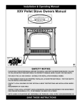
MULTI FUEL PARLOR STOVE OPERATOR’S MANUAL Installation and Operation MF3700, MF3800 CumberlandStoveWorks.com CAUTION SAVE THESE INSTRUCTIONS • Important operating and maintenance instructions included. • Read, understand and follow these instructions for safe installation and operation. • Leave this manual with party responsible for use and operation. WARNING Please read this entire manual before installation and use of this pellet fuelburning room heater. Failure to follow these instructions could result in property damage, bodily injury or even death. • Do not store or use gasoline or other flammable vapors and liquids in the vicinity of this or any other appliance. • Do not overfire - If any external part starts to glow, you are overfiring. Reduce feed rate. Overfiring will void the warranty. • Comply with all minimum clearances to combustibles as specified. Failure to comply may cause a house fire. WARNING HOT! DO NOT TOUCH. SEVERE BURNS MAY RESULT. CLOTHING IGNITION MAY RESULT. Glass and other surfaces are hot during operation and cool down. • Keep children away. • CAREFULLY SUPERVISE children in same room as appliance. • Alert children and adults to hazards of high temperatures. • DO NOT operate with protective barriers open or removed. • Keep clothing, furniture, draperies and other combustibles away. CAUTION CAUTION Tested and approved for shelled field corn, approved pellets and cherry pits. Burning of any other type of fuel voids the warranty. ARDISAM .com Check building codes prior to installation. • Installation MUST comply with local, regional, state and national codes and regulations. • Consult local building or fire officials about restrictions and installation inspection requirements in your area. OMMF3700/3800 Rev. Date 06/09/08 © 2008 Ardisam, Inc. All Rights Reserved. Printed in USA. INSTALLATION AND OPERATION MANUAL MF3700, MF3800 Models TABLE OF CONTENTS Warranty.........................................................................................................................................................................................2 Registration, Service & Maintenance Log..........................................................................................................................3 Warnings & Cautions...................................................................................................................................................................4 Automatic Safety Features.................................................................................................................................................................5 Introduction..................................................................................................................................................................................6 Burning Solid Fuels............................................................................................................................................................................6 Specifications................................................................................................................................................................................8 Unpacking & Assembly................................................................................................................................................................9 controller options..................................................................................................................................................................10 Installation..................................................................................................................................................................................11 Stove Placement..............................................................................................................................................................................11 Floor Protection Requirements.........................................................................................................................................................11 Clearance to Combustibles..............................................................................................................................................................12 Venting............................................................................................................................................................................................13 Type of Vent.....................................................................................................................................................................................13 Pellet Vent Installation......................................................................................................................................................................13 Vent Termination Clearances...........................................................................................................................................................14 Venting Installation Examples..........................................................................................................................................................14 Installing RemoteThermostat............................................................................................................................................................14 Outside Air Connection.....................................................................................................................................................................15 Mobile Home....................................................................................................................................................................................15 Operating Instructions..........................................................................................................................................................15 Understanding the TRI-X Controller.................................................................................................................................................15 Operating Stove...............................................................................................................................................................................16 Fuel Range Selection.......................................................................................................................................................................17 Starting Fire and Electric Ignite Screens..........................................................................................................................................17 Thermostat control options...............................................................................................................................................................18 Explanation of Fault Message Screens............................................................................................................................................18 Normal Care & Maintenance...................................................................................................................................................21 Troubleshooting & Repair......................................................................................................................................................22 Ordering Replacement Parts............................................................................................................................................................22 Troubleshooting Guide.....................................................................................................................................................................23 Parts...............................................................................................................................................................................................24 Wiring Diagram............................................................................................................................................................................29 800-345-6007 CumberlandStoveWorks.com Page INSTALLATION AND OPERATION MANUAL MF3700, MF3800 Models WARRANTY Limited lifetime Warranty Ardisam, Inc., a Manufacturing Company warrants this Cumberland Stove Works Multi-Fuel Parlor Stove to be free from defects in the material or workmanship. For the lifetime of the product, Ardisam will furnish 100% parts and labor to correct any defect caused by faulty material or workmanship. For other warranty repairs, please read the three year warranty listed below. All repairs made under warranty must have prior approval from Ardisam, Inc. by calling our customer service department at 800-345-6007. tHREE Year Warranty All electrical components such as but not limited to blowers, wiring, vacuum switches, speed controls, control boxes, switches, pilot assembly, valves, thermostats and igniters are covered under Ardisam, Inc.’s three-year warranty program. Our fire pots and labor are also covered under the three year warranty. THIS WARRANTY IS LIMITED TO DEFECTIVE PARTS – REPAIR AND/OR REPLACEMENT AT ARDISAM, INC.’S OPTION AND EXCLUDES ANY INCIDENTAL AND CONSEQUENTIAL DAMAGES CONNECTED THEREWITH. This warranty is not transferable and supersedes all other warranties either expressed or implied and all other obligations to liabilities on our part. Ardisam, Inc. does not assume, and does not authorize any other person to assume for us, any liability in connection with the sale of our products. The warranty applies only to products which have not been subjected to negligent use, misuse, alteration, accident or repairs made by anyone not certified by Cumberland Stove Works. This guarantee is void unless the warranty card is properly filled out and returned to Ardisam, Inc., Cumberland, WI, at the time of purchase. Cumberland Stove Works, A Division of Ardisam, Inc. 1360 First Avenue; P.O. Box 666 Cumberland, Wisconsin 54829 800-345-6007 · Fax (715) 822-2223 E-mail: [email protected] Page CumberlandStoveWorks.com 800-345-6007 INSTALLATION AND OPERATION MANUAL MF3700, MF3800 Models REGISTRATION, SERVICE AND MAINTENANCE LOG Record the model number and serial number in the space provided for easy reference. Fill out and mail the registration card located in the parts packet or register online at www.cumberlandstoveworks.com. Warranty is valid only if the completed registration is received by Ardisam, Inc. within 30 days of purchase. OWNERSHIP RECORDS Dealer’s Name: Dealer’s Address: City: State/Province: Model Number: Serial Number: Zip Code/Postal Code: Date of Purchase: Notes: SERVICE DATE 800-345-6007 SERVICE TECHNICIAN SERVICE DESCRIPTION CumberlandStoveWorks.com Page INSTALLATION AND OPERATION MANUAL MF3700, MF3800 Models WARNINGS AND CAUTIONS warning caution INDICATES A HAZARD WHICH, IF NOT AVOIDED, COULD RESULT IN DEATH OR SERIOUS INJURY AND/OR PROPERTY DAMAGE. INDICATES A HAZARD WHICH, IF NOT AVOIDED, MIGHT RESULT IN MINOR OR MODERATE INJURY AND PROPERTY DAMAGE. Read this entire manual before you install and use your new parlor stove. Failure to follow instructions may result in property damage, bodily injury, or even death. Proper installation of this stove is necessary for safe and efficient operation. Installing this product improperly may result in a house fire and personal injury. All applicable building codes for your location must be followed. In areas where building codes require additional steps to the installation of this product not included in this manual, the building codes will take precedent and must be followed. Contact your local building inspector to obtain any necessary permits or inspection guidelines before installing the product. Children and adults should be alerted to the hazards of high surface temperatures and should stay away to avoid contact to skin and/or clothing. Young children should be carefully supervised when they are in the same room as the stove. Clothing and other flammable materials should not be placed on or near this unit. Flammable or explosive liquids such as gasoline, naphtha, alcohol, or engine oil must NEVER be used in or around stove. These liquids must be stored in a separate room as the open flame in the fire box could ignite the fumes of such liquids. DO NOT burn garbage in this unit. The burning of other solid fuels such as cord wood or wood chips in this stove is not permitted. Any fuels not certified by Cumberland Stove Works which are burned in this stove will void the warranty. DO NOT route power cord in high traffic areas. A power surge protector plugged into a grounded 110 volt power source is required. DO NOT install a flue damper in the exhaust venting system of this unit. DO NOT connect this unit to a chimney flue servicing another appliance. Do not install in a sleeping room. DO NOT connect to any air distribution duct or system. do not connect directly to a masonry chimney. Do not terminate vent in any enclosed or semienclosed area, such as; carports, garage, attic, crawl space, under a sun deck or porch, narrow walkway or closed area, or any location that can build up a concentration of fumes such as a stairwell, covered breezeway etc. Contact local building or fire officials about restrictions and installation inspection requirements in your area. Contact your local authority (such as municipal building department, fire department, fire prevention bureau, etc.) to determine the need for a permit. The Cumberland Stove Works parlor stove is designed to burn dry shelled field corn, wood pellets, and cherry pits. A working smoke detector is required and must be installed in the same room as the stove. This stove is not intended for use in commercial applications. Door and ash pan must be closed and latched during operation. Notify your insurance company of parlor stove installation. This installation must conform with local codes. In the absence of local codes you must comply with ASTM E1509, (UM) 84-hud, ulc/ordC-1482. The structural integrity of the manufactured home floor, wall, and ceiling/roof must be maintained. Keep combustible materials (such as grass, leaves, etc.) at least 3 feet away from the flue outlet on the outside of the building. This stove should not be used as the only source of heat in the house. Power outages and periodic maintenance will result in a total loss of heat. Do not leave hopper door open while unattended. Page CumberlandStoveWorks.com 800-345-6007 INSTALLATION AND OPERATION MANUAL MF3700, MF3800 Models caution WARNING Installation and repair of this parlor stove should be done by a qualified service person. The appliance should be inspected before use and at least annually by a qualified service person. It is imperative that control compartments, fire box, and circulating air passageways of the stove be kept clean. The operation of exhaust fans such as bathroom fans, attic fans, etc. might starve the parlor stove of combustible air creating a negative pressure in the room. Provide adequate ventilation of the room accompanying the parlor stove. If not, the pressure switch may shut off operation of the parlor stove. The moving parts of this stove are propelled by high torque electric motors. These parts can cause severe damage to body parts that get near them. Keep all body parts away from auger and fans while the stove is plugged into an electrical outlet. These moving parts may begin to move at any time the stove is plugged in. If the electrical power fails any time when the stove is hot, keep all stove doors closed. Vent surfaces can get hot enough to cause burns if touched. Noncombustible shielding or guards may be required. Install vent at clearances specified by the vent manufacturer. If the electrical power fails any time when the stove is hot, keep all stove doors closed. THE AUTOMATIC SAFETY FEATURES MUST NOT BE BYPASSED. When resetting overtemp never use any conductors. Could Cause Electrical Shock and/or damage to stove. AUTOMATIC SAFETY FEATURES Power Outage During a power outage, the stove will shutdown safely. It will not automatically restart when the power returns. If the stove is still at operating termperature when power returns, the convection fan will circulate the remaining heat in the stove. See Lighting Instructions. Overheating Over Fire Protection: If the stove is being over fired or burning too hot, the high limit switches will automatially shut down the stove to avoid damage to components. Allow the stove to cool at least one hour before relighting. The exhaust over temp is located in the rear of the stove (figure 1), the auger over temp is located on the auger housing (figure 2). Both are reset by manually pressing in the button located between the wire terminals. All venting joints, whether vertical or horizontal, should be made gas-tight with recommended sealants specified by vent manufacturer. According to HUD (Housing & Urban Development) requirements, when installed in a mobile home, this stove must be grounded directly to the steel chassis of the mobile home and bolted to the floor. Direct air access must be provided, use a Fresh Air Kit. For use in the United States. Approved for installation in mobile homes. Cumberland Stove Works, manufacturer of this appliance, reserves the right to alter its products, specifications and/or price without notice. push to reset Figure 1: Overtemp Reset Button in Back Panel push to reset Figure 2: Overtemp Reset Button on auger housing 800-345-6007 CumberlandStoveWorks.com Page INSTALLATION AND OPERATION MANUAL MF3700, MF3800 Models INTRODUCTION Congratulations on your investment in quality. Thank you for purchasing a Cumberland Stove Works Multi Fuel Parlor Stove from Ardisam, Inc. We have worked to ensure that the multi fuel burning stove meets the highest standards for usability and durability. With proper care, your stove will provide many years of service. Please read this entire manual before installation and use. BURNING SOLID FUELS WARNING NEVER BURN SEED CORN IN THE STOVE. Seed corn is treated with chemical pesticides that are harmful or fatal if swallowed, seed corn is dangerous to have in the house, especially where children can reach it. never burn “deer corn”. it frequently contains molasses sugars. NEVER BURN CORN WITH A HIGH WAX CONTENT. Ashes need to be removed from the stove periodically. See Normal Care & Maintenance section for cleaning procedure. The parlor stove, due to the nature of solid fuels, will require brief periodic attention. A few moments of adjustment and cleaning from time to time is an important part of burning solid fuels. This parlor stove has been designed to burn dry shelled corn, wood pellets and cherry pits. SHELLED CORN DO NOT store items such as start pellets or burn gel in parlor stove or within installed clearances of parlor stove. CAUTION Burning only corn with the recommended moisture content will assure longer stove life and less frequent cleaning. • Corn must contain less than 14% moisture content. Wet corn will rapidly deteriorate stove components, reduce efficiency and void all warranties. Purchase a moisture tester if in doubt. • Corn must be clean and free from debris. Never burn corn right from the field. Damage caused by dirty corn is not covered by the product warranty. Ask for screened corn only. Stalk parts, excessive fines and cob remnants will clog the air flow holes in burn plate. Check the corn for foreign objects. • Store the corn supply in a dry place and keep the bags or container sealed to prevent it from absorbing excess moisture. Test the moisture content periodically to ensure the proper dryness. • There are many varieties of corn. Each variety has unique characteristics including the shape and size of the kernel. As corn characteristics change, the fuel range may have to change accordingly. See figure 3. Page Range 4 Levels 1-6 Range 3 Levels 1-6 Range 2 Range 1 Levels 1-6 Levels 1-6 Lowest Feed Rate/ Combustion Airflow Highest Feed Rate/ Combustion Airflow Figure 3: Feed Rate Chart CumberlandStoveWorks.com 800-345-6007 INSTALLATION AND OPERATION MANUAL MF3700, MF3800 Models PELLETS • As with corn, find a consistent pellet supplier. Pellets will vary in content and burn characteristics from supplier to supplier. A consistent supply of pellets will result in a more consistent and efficient burn. • Before burning, check the pellets for foreign objects. The stove warranty will not cover damage done to the stove due to foreign objects in the fuel supply. • Store the pellets in a dry place to prevent them from absorbing added moisture. • To decrease dust buildup, the hopper will need to be vacuumed out after every 6-8 bags of pellets or more often if the pellets are poor quality. You may have to screen each bag of pellets if dust becomes a problem. • Wood pellets are generally produced out of wood waste such as sawdust and shavings. The raw material is dried, mechanically fractioned to size and extruded under intense pressure into pellets. Wood pellets need to be protected from direct water penetration. If exposed to water droplets from condensation they will gradually decompose and loose their effectiveness as a fuel. The decomposition involves expanded volume and over time a gradual chemical breakdown. • Cherry Pits are the woody remains of processed cherries. This fuel can be found affordably in regions of the country that process cherries. 800-345-6007 CAUTION B urning wood pellets according to recommendations will assure longer stove life and less frequent cleaning. THE USE OF GRATES OR OTHER METHODS OF SUPPORTING THE FUEL IS NOT AUTHORIZED IN THIS PARLOR STOVE. CumberlandStoveWorks.com Page INSTALLATION AND OPERATION MANUAL MF3700, MF3800 Models SPECIFICATIONS CAUTION Model Number MF3700, MF3800 BTU/hour input (1) 45,000 max Heating Capacity (2) 1,200 Sq. Ft. Electrical Rating (3) 110 Volts, 15 Amp, 60 Hz Power Consumption Controller = 2.0 Watts Stove = 200 Watts Fuel Storage Capacity 62 lbs. Flue Size (4) 3 in. Width 22 in. Height 40 in. Depth 22 in. Weight 287 lbs. this installation must conform with local codes. in the absence of local codes you must comply with ASTm e1509, (UM) 84-hud, ulc/ordc-1482. cumberland stove works, manufacturer of this appliance, reserves the right to alter its products, their specifications and/or price without notice. (1) Heat output will vary, depending on the brand, type and quality of fuel and the moisture content. Consult your dealer for best results. (2) Based on post 1982 home construction, requiring 35 BTU/Hr. per Sq. Ft. (3) Install per NFPA 70 and follow all state and local codes, contact licensed electrical contractor for assistance. (4) Install per NFPA 211 and follow all state and local codes, contact licensed installers for assistance. Listing label: Tested to the following stardards: UL1482, ASTM E1509, ULC/ORD-C1482-M1990 GLASS SPECIFICATIONS This stove is equipped with 5mm ceramic glass. Replace Page CumberlandStoveWorks.com 800-345-6007 INSTALLATION AND OPERATION MANUAL MF3700, MF3800 Models UNPACKING AND ASSEMBLY Unpack all hardware located in the units hopper and ash pan. The following should be included: 4 - legs (710008) w/ levelers (725010) 4 - tie-down straps (700136) 1 - firepot cleaning rod (700076) 1 - cleaning rod spring (720053) 1 - hopper lid handle (730006) 1 - power cord (720045) 1 - scraper tool (700225) 1 - door (700311) with glass (720002) and handle (700351, 700359) 1 - controller (730053) 1 - steel mounting bracket (700349) 1 - pre-made parts bag (small) which includes: 4 - 1/4-20 x 2” tie-down bolts (725015) 2 - 8-32 x 3/8” hopper lid handle bolts (725012) 12 - 5/16-18 x 3/4” leg bolts (1501) 4 - #8-18 controller bracket screws (725027) Figure 4: Leg Assembly MOUNT LEGS NOTE: Stove is heavy. Team lifting is recommended. 1. Gently tilt the stove on its side. 2. Assemble the legs using provided (12) leg bolts as shown in figure 4. Figure 5: Hopper Door Handle Assembly NOTE for mobile home installation: If unit is to be used in a mobile home, you must install the (4) tie-down straps to the stove now. Refer to page 15 for instructions. 3. After all bolts have been tightened, set the stove back up on its legs. MOUNT HANDLE TO HOPPER DOOR 1. Using a Phillips screwdriver, attach hopper handle to hopper door using the pre-drilled holes. See figure 5. ASSEMBLE FIREPOT CLEANING ROD Figure 6: Ash Shuttle Rod Assembly 1. Thread spring over non-threaded end of rod. 2. Place threaded end of firepot cleaning rod through decorative casting and screw into fire pot. See figure 6. NOTE: It is important for the fire pot to slide freely in and out of the pot holder. Fire pot must seal tight when pushed in. Power Cord Receptacle PLUG IN POWER CORD 1. Plug power cord into the back of stove. See figure 7. Figure 7: Ash Shuttle Rod Assembly 800-345-6007 CumberlandStoveWorks.com Page INSTALLATION AND OPERATION MANUAL MF3700, MF3800 Models MOUNTING THE CONTROLLER The CSW MF Series Stove has three different controller mounting options: 1. Back of the stove with controller visible.You may mount the conrollter on either side of the rear of the stove (see figure 8) so it is visible during operation. To do so use the metal mounting bracket and the (4) self-tapping screws ((2) through the plastic bracket and (2) through the back panel of the stove). Attach through the pre-drilled holes. Note: Self-tapping screws must penetrate hopper. 2. Back of the stove with controller hidden. You may mount the controller on either side of the stove (see figure 9). So it is not visible during operation. Attach the plastic mounting bracket to the pre-drilled holes on either side of the stove using the (2) self-tapping screws. Note: Self-tapping screws must penetrate hopper. 3. Wall mounted (figure 10). You may mount the controller on the wall next to the unit using two drywall screws. It is best to embed the screws into a stud. Use a stud finder to locate studs in the wall. Figure 8: Controller on metal bracket in back. PLUG STOVE INTO CONTROLLER After mounting the controller plug the phone cord from the back of the stove to the underside of the controller. MOUNT DOOR Take off protective cardboard. Hang door on hinges making sure it’s seated properly so latch is aligned with latch cut-out. LATCH ADJUSTMENT The door gasket may settle after use and adjustment to latch is necessary to ensure proper seal. To adjust latch remove roll pin and swap washers from the inside of door to the outside of the door. Replace roll pin and inspect door fit. Figure 9: Controller on plastic bracket in back. Figure 10: Controller on wall. Page 10 CumberlandStoveWorks.com Figure 11: Door Latch Adjustment. 800-345-6007 INSTALLATION AND OPERATION MANUAL MF3700, MF3800 Models INSTALLATION It is recommended the stove be installed and serviced by authorized professionals who are certified by the National Fireplace Institute (NFI) as NFI Pellet Specialists. Proper installation of this stove is necessary for safe and efficient operation. Installing this product improperly may result in a house fire and personal injury. All applicable building codes for your location must be followed. In areas where building codes require additional steps to the installation of this product not included in this manual, the building codes will take precedent and must be followed. Contact your local building inspector to obtain any necessary permits or inspection guidelines before installing the product. STOVE PLACEMENT Sketch out a plan for installing the stove including dimensions before permanent placement. When determining the location for the stove, wall stud location is critical. You may need to adjust the location of the stove to avoid trying to vent through a wall stud. Before placing the parlor stove, connect the vent and allow for minimum clearance to combustible walls. FLOOR PROTECTION REQUIREMENTS The stove must be installed on a noncombustible floor, with proper floor protection, or on a masonry hearth. The hearth or noncombustible floor protector must extend a minimum of 6” in front, and 4” from each side. When a clean out t-vent is installed in the inside of a home, the floor protector must extend 2” beyond rear of t-vent. See figure 12. When stove is vented straight through the wall and the clean out t-vent is on the exterior of the home, the minimum clearance is 3” from the back of the stove to the edge of floor protector. See figure 13. The minimum floor protector material is 24 GA. sheet metal. 3” 4” 6” Figure 12 READ THIS ENTIRE MANUAL BEFORE YOU INSTALL AND USE THIS STOVE. fAILURE TO FOLLOW THE INSTRUCTIONS MAY RESULT IN PROPERTY DAMAGE, BODILY INJURY, OR EVEN DEATH. DO NOT INSTALL A FLUE DAMPER IN THE EXHAUST VENTING SYSTEM OF THIS UNIT. DO NOT CONNECT THIS UNIT TO A CHIMNEY FLUE SERVING ANOTHER APPLIANCE. Children and adults should be alerted to the hazards of high surface temperatures and should stay away to avoid bumPs to skin and/or CLothing. Y oung children should be carefully supervised when they are in the same room as the stove. Clothing and other flammable materials should not be placed on or near this unit. CAUTION this stove should not be used as the only source of heat in the house. Power outages and periodic maintenance will result in a total loss of heat. CONTACT LOCAL BUILDING OR FIRE OFFICIALS ABOUT RESTRICTIONS AND INSTALLATION INSPECTION REQUIREMENTS IN YOUR AREA. CONTACT YOUR LOCAL AUTHORITY (SUCH AS MUNICIPALBUILDINGDEPARTMENT,FIRE DEPARTMENT, FIRE PREVENTION BUREAU, ETC.) TO DETERMINE THE NEED FOR A PERMIT. KEEP COMBUSTIBLE MATERIALS (SUCH AS GRASS, LEAVES, ETC.) AT LEAST 3 FEET AWAY FROM THE FLUE OUTLET ON THE OUTSIDE OF THE BUILDING. Installation and repair of this parlor stove should be done by a qualified service person. The appliance should be inspected before use and at least annually by a qualified service person. It is imperative that control compartments, fire box, and circulating air passageways of the stove be kept clean. 2” 4” warning 4” 4” 6” Figure 13 PARLOR STOVE FLOOR PAD CLEARANCES 800-345-6007 CumberlandStoveWorks.com Page 11 INSTALLATION AND OPERATION MANUAL MF3700, MF3800 Models CLEARANCES TO COMBUSTIBLES NOTE: These are minimum clearances to combustible walls established by the ASTM testing lab. 3” 3” 4” 3” 4” 4” 3” 6” 6” 4” Figure 14 STRAIGHT INSTALLATION Through Wall Figure 15 CORNER INSTALLATION Through the Wall Vents 3” 2” 2” 4” 3” 4” 4” 6” 4” 6” Figure 16 STRAIGHT INSTALLATION INTERIOR VERTICAL VENTS Figure 17 CORNER INSTALLATION Interior Vertical Vents NOTE: When interior vertical pellet vent is used for installation, the clearance to the back wall is determined by the vent size used. Install vent at clearance specified by the vent manufacturer. Take into consideration any upward turning elbows or T’s. Page 12 CumberlandStoveWorks.com 800-345-6007 INSTALLATION AND OPERATION MANUAL MF3700, MF3800 Models VENTING Consult vent manufacturer’s specifications and recommendations for all venting installations. The following installation guidelines must be followed to ensure conformity with both the safety listing of this stove and to local building codes. Note: Where passage through a wall, or partition of combustible construction is desired, the installation shall conform to CAN/CSA -8365. TYPE OF VENT Pellet venting pipe (also known as L vent) is constructed of two layers with air space between the layers. This air space acts as an insulator and reduces outside surface temperature of pipe to allow a clearance to combustibles. A UL listed 3” or 4” type L pellet vent exhaust system must be used for installation and attached to the pipe connector provided on the back of the stove. Use a 3” to 4” adapter for 4” pipe. A cap must be used at the termination of type L vent chimneys. For elevations above 2,500 feet above sea level, a 4” L is required. PELLET VENT INSTALLATION Termination MUST exhaust above air inlet elevation. It is recommended to install at least 3’ of vertical pellet vent pipe. This will create some natural draft to prevent the possibility of smoke or odor during appliance shutdown and to keep exhaust from causing a nuisance or hazard from exposing people or shrubs to high temperatures. WARNING DO NOT CONNECT THIS UNIT TO A CHIMNEY FLUE SERVING ANOTHER APPLIANCE. DO NOT INSTALL A FLUE DAMPER IN THE EXHAUST VENTING SYSTEM OF THIS UNIT. do not connect directly to a masonry chimney. Do not terminate vent in any enclosed or semienclosed area, such as; carports, garage, attic, crawl space, under a sun deck or porch, narrow walkway or closed area, or any location that can build up a concentration of fumes such as a stairwell, covered breezeway etc. CAUTION Vent surfaces can get hot enough to cause burns if touched. Noncombustible shielding or guards may be required. PELLET VENT MUST MAINTAIN MINIMUM clearances specified by vent manufacturer for CLEARANCE TO ANY COMBUSTIBLEs. INSTALL VENT AT CLEARANCES SPECIFIED BY THE VENT MANUFACTURER. All venting, whether vertical or horizontal, joints should be made Gas-tight with recommended sealants. The installation must include a clean out tee to enable collection of fly ash and to permit periodic cleaning of the exhaust system. Total length of horizontal vent must not exceed 10 feet. The maximum recommended vertical venting height is 18 feet. All joints for pellet vent are required to be fastened with at least three screws and all pellet vent connections must be sealed according to the vent manufacturer’s recommendations. The area where the vent pipe goes through to the exterior of the home must be sealed with silicone or other means to maintain the vapor barrier between the exterior and the interior of the home. 800-345-6007 CumberlandStoveWorks.com Page 13 INSTALLATION AND OPERATION MANUAL MF3700, MF3800 Models VENT TERMINATION CLEARANCES CLEARANCE 4 feet Clearance below or beside any door or window that opens. 1 foot Clearance above any door or window that opens. 3 feet Clearance from any adjacent building. 7 feet Clearance from any grade when adjacent to public walkways. 2 feet Clearance above any grass, plants, or other combustible materials. 3 feet Clearance from any forced air intake of any appliance. 2 feet Clearance below eaves or overhang. 1 foot Clearance horizontally from combustible wall. 3 feet Clearance above the roof. 2 feet Clearance above the highest point on the roof within 10 feet. Installing REMOTE Thermostat The MF Parlor Stove can be run thermostatically by purchasing any milivolt thermostat (sold separately). This step is optional and not required for MF Parlor Stove to operate. Mount thermostat according to manufacturer specifications. Using a small flat head screw driver, tighten remote thermostat wires into pins 7 and 8. See figure 18. remote thermostat terminals Figure 18: Remote Thermostat Terminals VENTING INSTALLATION EXAMPLES Figure 19: STRAIGHT INSTALLATION Outside Vertical Rise, Through Wall Installation Page 14 Figure 20: STRAIGHT INSTALLATION Inside Vertical Rise, Horizontal Termination CumberlandStoveWorks.com 800-345-6007 INSTALLATION AND OPERATION MANUAL MF3700, MF3800 Models OUTSIDE AIR CONNECTION WARNING Connection from the intake pipe (2” diameter pipe in rear of stove) to the outside of the house is REQUIRED for mobile home installation. It is recommended in tightly sealed homes with exhaust fans such as kitchen or bathroom fans. This will eliminate poor performance due to negative pressure. DO NOT CONNECT TO ANY AIR DISTRIBUTION DUCT OR SYSTEM. do not install in a sleeping room. CAUTION Only noncombustible pipe 2” (or greater) in diameter is approved to use for outside air connections (straight or flexible). PVC pipe is NOT approved and should NEVER be connected to the stove. THE OPERATION OF EXHAUST FANS SUCH AS BATHROOM FANS, ATTIC FANS, ETC. MIGHT STARVE THE PARLOR STOVE OF COMBUSTIBLE AIR CREATING A NEGATIVE PRESSURE IN THE ROOM. PROVIDE ADEQUATE VENTILATION IN THE ROOM ACCOMPANYING THE PARLOR STOVE. IF NOT, THE PRESSURE SWITCH MAY SHUT OFF OPERATION OF THE PARLOR STOVE. If the air inlet is connected to the outside, it MUST be terminated with a vertical 90º bend (down) or with a wind hood. Failure to do so could result in a burn back during high winds blowing directly up the air inlet during a simultaneous power failure. Blockage, excessive length, or extra bends in the air intake pipe will starve the stove of combustion air. A 90º bend is equivalent in restriction to approximately 30” of straight inlet pipe. THE STRUCTURAL INTEGRITY OF THE MANUFACTURED HOME FLOOR, WALL, AND CEILING/ROOF MUST BE MAINTAINED. UNDERSTANDING THE TRI-X CONTROLLER 1 - On - Starts stove operation when instructed. MOBILE HOME 2 - Off - Turns off stove operation at anytime Installation in a mobile home should be in accordance with the manufactured home and safety standard. Department of Housing and Urban Development (HUD) CITE: 24CFR3280.707 stating this stove must be vented to the outside. In addition to the standard installation instructions, the following requirements are mandatory for installation in a mobile home: 1. Stove must be bolted to the floor. Stove will have four tie-down straps that bolt to the feet and the floor. 2. Stove must have an outside air source. B Note: Off Button will not instantly extinguish fire 3 & 4 - Temp Up, Temp Down Controls heat levels 1-6 and local thermostat temperature. 5 & 6 - Fan Up, Fan Down Controls level of convection fan (the fan that circulates warm air through the room). 7 - Add Fuel Pressing the Add Fuel Button will turn on the feed auger. A L.E.D. light on the top right corner will be on when the auger is running. Pressing this button once will turn the auger on for one minute. If the button is pressed within the minute, the auger will then turn off. 8 - Thermostat On/Off 3. Stove must be electrically grounded to the steel chassis of the mobile home. Push to scroll through thermostat options; local, remote, or none. 4. All vertical chimney vents must have wall supports. Allows user to change heat ranges. Allows user to browse heat ranges. MF3800 users have the option of running the igniter during normal operation. 5. All exhaust systems must have a spark arrestor. 9 - Scroll 10 - Enter - Chooses the top selection of the screen C 1 3 5 7 9 2 4 6 8 10 B Tie-down Straps Lag Screw Figure 21: Mobile Home Anchor & Leg Assembly C 800-345-6007 Figure 22: Controller key pad. CumberlandStoveWorks.com Page 15 INSTALLATION AND OPERATION MANUAL MF3700, MF3800 Models OPERATING STOVE Once the stove has been properly installed and plugged into a grounded surge protector you are ready to begin operation. IMPORTANT: Before filling the hopper make sure all shipping and packaging items are removed from the hopper and there are no obstructions in the auger housing opening. Fill the hopper with an approved solid fuel and close the lid. The first screen you will see upon power up is the model and version of software loaded in the control. It will then default to the Fuel Range Selection Mode. FUEL RANGE SELECTION The CSW Multi Fuel Parlor stove has four fuel ranges and six heat output Levels within each fuel range. This gives the stove 24 levels of variability maximizing burn with your chosen fuel. Range 1 Level 1 is the lowest feed rate/combustion airflow and Range 4 Level 6 is the highest feed rate/combustion airflow. See figure 23. RANGES FOR APPROVED FUELS • Wood Pellets 2-3-4 • Cherry Pits 4 SELECTING THE RANGE The control will offer two selections on the screen. To browse through the range selections use the SCROLL button. To choose a range scroll through until the desired Range is on top and press ENTER. Range may be changed at anytime during stove operation by pressing the SCROLL Levels 1-6 Range 3 Range 2 Range 1 Levels 1-6 Levels 1-6 Figure 23: Feed rate chart. Page 16 button. STARTING A FIRE After the Range has been loaded the controller will then instruct you to light the fire. MF3700 stove controllers will read as follows: LIGHT FIRE PUSH ON BUTTON Stoves equipped with electric ignition (model MF3800) will have the option of starting the fire manually or automatically with the igniter. The screen will read as follows: Pushing SCROLL will send the controller to the LIGHT FIRE PUSH ON BUTTON. See Manual Lighting Instructions before starting fire or pushing ON. For electric ignition read ELECRTRIC IGNITION INSTRUCTIONS before pressing ENTER. MANUAL LIGHTING INSTRUCTIONS IMPORTANT: Before lighting the stove for the first time, make sure that no shipping items have been left inside the firebox or ash pan. When initially filling an empty hopper you must prime the feed auger. To prime the auger press the ADD FUEL button. This will turn on your auger on for one minute or until the ADD FUEL button is pressed again. Run feed auger until you see fuel start to drop into the firepot. Note: The parlor stove has been designed with a safety switch on the hopper lid. The auger will not run with the hopper door open. Levels 1-6 Lowest Feed Rate/ Combustion Airflow never put starting pellets or burn gel into the hopper of the stove. This could result in death or serious injury and or property damage. Doing so will void all warranties. electric ignite yes no • Corn 1-2 Range 4 WARNING Highest Feed Rate/ Combustion Airflow Fill the firepot with about one cup of starting pellets or wood pellets. If wood pellets are used, squirt about two tablespoons of burn gel on pellets. Light the material in firepot using a match or a grill type CumberlandStoveWorks.com 800-345-6007 INSTALLATION AND OPERATION MANUAL MF3700, MF3800 Models lighter, close the door and press ON key. The sound you hear after the ON key is pushed is the exhaust fan running. After the ON key is pressed the control will read as follows: starting fire level 1 ELECTRIC IGNITiON INSTRUCTIONS (MF3800 only) After the Range has been loaded the controller will then read as follows electric ignite yes no IMPORTANT: Before lighting the stove for the first time, make sure that no shipping items have been left inside the firebox or ash pan. When initially filling an empty hopper you must prime the feed auger. To prime the auger press the ADD FUEL button. This will turn the auger on for one minute or until the ADD FUEL button is pressed again. Run the feed auger until you see fuel start to drop into the firepot. Note: The parlor stove has been designed with a safety switch on the hopper lid. The auger will not run with the hopper door open. Once the auger is primed pressing ENTER will start the electronic ignition sequence. Note: Pre loading the firepot isn’t necessary for electric ignition; the program is designed to automatically load the firepot. The noises you will hear during electric ignition are the combustion fan and air pump running. The screen will read as follows: electric ignite level 1 STARTING FIRE AND ELECTRIC IGNITE SCREENS (MF3800 only) The starting fire and electric ignition sequences have been designed to take a cold stove up to normal operating temperature. These are preset feed rates and fans speeds set by CSW to ensure the ignition of multiple types of fuels. 800-345-6007 During starting fire and electric ignition sequences you may change the level by pressing the TEMP UP or TEMP DOWN buttons. During starting fire and electric ignition sequences you may choose to run your stove thermostatically by pressing the THERMOSTAT ON/OFF button. See Thermostatic Control Operation. At any time you may add more fuel to the firepot by pressing the ADD FUEL button. Note: the feed auger will stay on for one minute or until the ADD FUEL button is pressed again. During starting fire and electric ignition sequences the convection fan (the fan that circulates warm air throughout room) will start once stove has reached 110 degrees. To control convection fan speed use Fan Up and Fan Down buttons (Buttons 3 and 8 in Figure 22). Note: Hot stoves need air circulating through them at all times to prevent overheating the electronic controls. Therefore, once proof of fire is made the convection fan will continue to run. After the stove runs it’s starting fire or electric ignition sequences the controller will read RANGE 1-4 (will display chosen fuel range) LEVEL 1-6 (will display chosen heat output level). This is the normal operating screens for the MF series parlor stove. NORMAL OPERATION During normal manual operation of the stove the controller will read as follows: temp 72 range 1-4 level 1-6 At any time during normal operation you will be able to change the Fuel Range by pressing the SCROLL button. (MF 3800 only) At any time during normal operation you will be able to run the igniter by pressing the SCROLL button during the normal operating At anytime during normal operation you may change the heat level by pressing the TEMP UP or TEMP DOWN buttons. Note: if the stove is being controlled by the local thermostat the TEMP UP and TEMP DOWN buttons control the thermostat setpoint. If the stove is being controlled by the remote thermostat the TEMP UP or TEMP DOWN buttons have no effect on the heat output. At anytime during normal operation you may turn on or off the thermostatic control by pressing the THERMOSTAT ON/OFF button. CumberlandStoveWorks.com Page 17 INSTALLATION AND OPERATION MANUAL MF3700, MF3800 Models THERMOSTATIC CONTROL OPERATION The stove has been designed to be run thermostatically two different ways. There is a built-in thermostat in the controller, or a remote thermostat can be installed (see INSTALLING REMOTE THERMOSTAT page 14). LOCAL T-STAT – The local thermostat is the thermostat located inside the controller display. To use this mode press the thermostat button until the following screen is displayed: WARNING never shut down your stove by leaving the hopper door open and unattended. This could create AN UNSAFE CONDITION IF THE DWELLING IS UNDER NEGATIVE PRESSURE. tstat off local tstat . The L.E.D. light located in the top right corner of the t-stat button will illuminate. During normal local thermostat operation the screen will display (for example) the following: stpt 72 temp 65 range 3 level 4 At anytime during normal operation you may press the OFF button to safely shut down the stove. IMPORTANT: NEVER UNPLUG YOUR STOVE WHILE THERE IS FUEL BURNING IN THE STOVE. The stove is designed to exhaust smoke through the vacuum created by the combustion fan. Doing so will cause combustion fan to stop and smoke will enter the room through air intake holes. EXPLANATION OF FAULT MESSAGE SCREENS During local thermostat operation the TEMP UP and TEMP DOWN buttons control the thermostat setpoint. REMOTE T-STAT – Remote T-STAT mode is chosen by pressing the T-STAT button until the following screen is displayed: remote tstat . During this thermostat mode the stove is controlled by a thermostat that is placed far from the stove. If the stove is in this mode the screen will display (for example) the following: remote * temp 72 range 3 level 4 NOTE: The asterick indicates that the termostat is calling for heat. To turn off the thermostat mode press the thermostat button until the following screen is displayed: Page 18 This will return the stove to manual operation where the heat level is controlled by using the Temp Up and Temp Down buttons. overtemp reset switch Allow the stove to cool then reset the overtemp switch located in the back of the unit under the exhaust vent. See figure 1. auger overtemp reset switch Allow the stove to cool then reset the overtemp switch located on the auger housing. See figure 2. Note: An overtemp switch will not reset until the stove has cooled to an acceptable level. To reset the switch you must manually press in the button located on the switch. See figures 1 & 2 for switch locations. In the event of an overtemp you must either select a lower fuel range for your selected fuel or clean the stove. Cleaning the stove is necessary to maximize heat transfer from the stove to the room. CumberlandStoveWorks.com 800-345-6007 INSTALLATION AND OPERATION MANUAL MF3700, MF3800 Models no proof of fire push on to start This means the stove went through the starting fire or electric ignition sequences and did not heat up enough to satify the proof of fire switch. Press ON button and restart the fire. Note: There may be fuel burning in the stove while it shows this screen. Use extreme caution when manually relighting a hot stove. vacuum fault check seals NORMAL CARE & MAINTENANCE CLEANING THE GLASS Only clean glass when the glass is cool. Wipe the glass clean with a dry or damp rag. If this does not clean the glass use any non-abrasive liquid spray. REMOVAL OF BROKEN CERAMIC GLASS Open the door and lift it from the hinges. Lay the door down on newspaper with glass clips facing you. Loosen the screws and take off the glass clips. Remove the broken glass carefully and discard. Reverse the above procedure for replacing new glass with new gasket. FIRE POT REMAINS This means that the stove doesn’t have enough vacuum in the firebox to run safely. Check that the fire box door is closed and that the seal is in good working condition. Check the ash pan door to make sure that the ash pan is firmly seated and that the seal is in good working condition. To clear this fault screen press the OFF button. If all doors are closed and sealed properly and the problem persists please call your dealer or CSW customer service for advanced trouble shooting. loss of fire off to reset This means that the stove has cooled to a point where it is no longer heating the room. Make sure that the hopper has fuel and that there are no obstructions that prevent fuel from entering the firepot. Pressing the off button will send the program to the STARTING FIRE (MF3700) or ELECTRIC IGNITE (MF3800) screen. Pressing the SCROLL button will send the program to the FUEL RANGE screen. STOVE SHUTDOWN To shut down stove operation press the OFF button at anytime. This will cause the stove to stop feeding fuel into the firepot, yet the combustion blower will continue to run exhausting all smoke until stove is off. When the stove runs out of fuel it will safely shut down automatically. Every time the hopper is filled with fuel the firepot should be emptied. To empty the firepot pull out and push in on the firepot cleaning rod. See figure 25. THE FIREPOT MUST BE PUSHED ALL THE WAY BACK AND SEATED AGAINST THE POTHOLDER FOR THE STOVE TO FUNCTION CORRECTLY. SOOT AND FLY ASH The products of combustion will contain small particles of fly ash. The fly ash and soot will collect in the exhaust venting system and restrict the flow of flue gasses. The exhaust venting system should be inspected at least once per month to determine if cleaning is necessary. If cleaning is necessary disassemble the exhaust vent and clean the individual parts. DISPOSAL OF ASHES Ashes should be placed in a metal container with a tight fitting lid. The closed container of ashes should be placed on a noncombustible floor or on the ground, well away from all combustible materials, pending final disposal. EXHAUST AND CONVECTION AIR FILTER Clean air filter (730008) regularly, replace if needed. See figure 24. DAILY MAINTENANCE The surfaces on the stove may be hot. Always wear protective gloves even when the stove is cool to the touch. IMPORTANT: NEVER UNPLUG YOUR STOVE WHILE THERE IS FUEL BURNING IN THE STOVE. • Clean the glass only when it is cool to the touch using any non-abrasive cleaner. Doing so will cause combustion blower to stop and smoke will enter the room through air intake holes. • After one hopper of fuel is consumed, the fire pot cleaning rod should be cycled (pulled out and pushed in) to drop the ashes into the ash pan. 800-345-6007 CumberlandStoveWorks.com Page 19 INSTALLATION AND OPERATION MANUAL MF3700, MF3800 Models AIR FILTER Replace air filter annually. Replacement filters can be ordered through your stove dealer. caution Do not operate stove with broken glass. Do not slam THE door shut. Do not strike glass. Do not use abrasive cleaners. Do not clean HOT glass. replace C E R A M I C G L A S S W I T H factory Authorized REPLACEMENT PARTS ONLY. tHE CLINKER WILL REMAIN HOT FOR SEVERAL MINUTES AFTER IT IS PULLED OUT OF THE Fire POT. ER AIR FILT Figure 24: Air filter placement. Page 20 CumberlandStoveWorks.com 800-345-6007 INSTALLATION AND OPERATION MANUAL MF3700, MF3800 Models • Complete the daily maintenance by checking the seal on the doors. Look for pellets that may have been left behind during loading. Check that each of the door seals are flush with the stove and sealing properly. WEEKLY MAINTENANCE • The fire pot and the area around it are cleaned using the special tool provided with the stove and the ash cleaning vacuum. It is important to remove any unburned pellets that may have fallen behind the burn pot. • To clean the fire pot with the cleaning tool, remove the fire pot by unscrewing the firepot cleaning rod from the fire pot. Remove the rod and the firepott. Remove the fire plate by lifting it out of pot holder (Figure 28). Brush all of the ash from beneath the fireplate into the ash pan. • Remove the ash pan and dump the ash into a metal container. • Cleaning of the exhaust system will depend upon the ash and debris content of your fuel. If your fuel has a high ash content and/or significant debris in it, the exhaust system will require weekly cleaning. Cleaner fuels will allow for monthly cleaning of the exhaust system. Clean out tees in the exhaust system make this task much easier. NOTE: A clean unit burns efficiently and will remain trouble free! warning When performing any internal electrical maintenance. • Moving parts inside of the cabinet may cause injury. Do not operate unit with panels removed or open. • HOT parts. Do not operate the unit with panel open. • Risk of electric shock. Disconnect power before servicing unit. • In the event of component failure, replace with the original factory equipment. CAUTION THIS IS A MINIMUM REQUIREMENT FOR SOOT AND FLY ASH REMOVAL. ASHES SHOULD BE PLACED IN A METAL CONTAINER WITH A TIGHT FITTING LID. THE CONTAINER SHOULD BE PLACED ON A NON-COMBUSTIBLE FLOOR, WELL AWAY FROM COMBUSTIBLE MATERIALS, PENDING FINAL DISPOSAL. iF ASHES ARE DISPOSED OF BY BURIAL IN SOIL OR OTHERWISE LOCALLY DISPERSED, THEY SHOULD BE RETAINED IN THE CLOSED CONTAINER UNTIL ALL CINDERS ARE NO LONGER WARM. MONTHLY MAINTENANCE • Remove the top baffle inside the firebox and clean the fly ash and soot on all exposed parts using a steel brush and ash cleaning vacuum. The use of a shop-vac is not recommended. Talk to any authorized dealer for information about the ash cleaning vacuum. SEASONAL CLEANING Once every year you must clean out all of the fuel in the hopper, firebox area, ash pan and fire pot area. Corn and pellets can accumulate moisture over the summer months causing the unit to rust and the fuel to mold. It is recommended that prior to shutting down the unit in the spring it is run on the high setting for about six hours to help clean out the heat exchanger system, venting system and fire box area. Firepot Cleaning Rod Ash Pan Figure 25: Ash pan and firepot cleaning rod. 800-345-6007 CumberlandStoveWorks.com Page 21 INSTALLATION AND OPERATION MANUAL MF3700, MF3800 Models When the unit is cleaned out, empty the hopper, take the venting apart and clean out the fly ash, rinse and let dry. Inspect the draft blower and clean out all areas. Clean the glass, doors and outer cabinet so that you are ready for the next heating season. Use of an ash vacuum makes cleaning easier and faster. TROUBLESHOOTING & repair At Ardisam, we build quality and durability into the design of our products; but no amount of careful design by us, and careful maintenance by you, can guarantee a repair-free life for your stove. Most repairs will be minor, and easily fixed by following the suggestions in the troubleshooting guide in this section. Figure 26: Cleaning tool. The guide will help you pinpoint the causes of common problems and identify remedies. For more complicated repairs, you may want to rely on your retailer, an authorized service center or Ardisam, Inc. A parts catalog is included in this section. We will always be glad to answer any questions you have, or help you find suitable assistance. To order parts or inquire about warranty, call or write us at the address found below, under the section ordering repair parts. ORDERING REPLACEMENT PARTS Parts can be obtained from the store where the stove was purchased or direct from the factory. To order from the factory- call, write or e-mail to: Figure 27: Heat exchanger scraper rod. Ardisam, Inc. 1360 First Avenue, Cumberland, Wisconsin 54829 1-800-345-6007 • 1-715-822-2415 E-mail: [email protected] Please include the following information with your order: 1. Part numbers 2. Part description 3. Quantity 4. Model number and serial number Figure 28: Removable fire plate. Page 22 CumberlandStoveWorks.com 800-345-6007 INSTALLATION AND OPERATION MANUAL MF3700, MF3800 Models WARNING TROUBLESHOOTING GUIDE Unplug stove before performing any maintenance. Problem NEVER SERVICE OR TOuCH THE FEED AUGER WITH THE STOVE PLUGGED IN. cause: Too rich air/fuel mixture ? Fire burns with a lazy, orange Make sure glass door is shut and Moisture content of fuel above 15%. Allow fuel to flame and/or fuel builds up in the sealed tightly. If not, adjust door handle dry. fire pot. Glass may become dirty. or replace gasket. Check inside parlor stove and exhaust pipes for Check that ash pan is in place and blockage. Tap inside walls of firebox, clean behind properly sealed. side access plates, clean fire pot and firebox vent holes above firebrick panel. Check that firepot is back all the way and sealing with the potholder Feed rate is too high for fuel, reduce range setting. Check that exhaust blower is running and venting properly. If not, check con- Check to make sure that exhaust vent is not nection and clean or replace. blocked. Problem CAUSE: Fire pot burns out of fuel ? Fire goes out or parlor stove Hopper empty, refill shuts down. Fuel may stop feed Hopper door is open. ing. Auger jams. Remove auger and clean. (Auger jams can be a problem if poor quality fuel is used. Or excessive fines (sawdust, corn cobs or husk) Problem are found in hopper. Auger jams are evident when the auger motor runs but no fuel is delivered. Hopper switch is not functioning properly or not conntected to the controller. CAUSE: Auger stops turning ? Fire goes out or parlor stove Feed auger has come loose. Check High limit sensor. Evident when parlor stove is exshuts down. Fuel may stop feed- to see if auger motor is turning and au- tremely hot. Allow parlor stove to cool for one hour ing. ger is not. and restart. Heat sensor. If the operating tem- Vacuum switch tripped. Caused by exhaust blower perature is too low the parlor stove will not running or venting blocked. Check blower, clean shutdown. or replace. Clean venting of blockage. Auger motor not operating. Inspect connection and replace if necessary. Problem ? Stove fans are not running. CAUSE: Loss of vacuum Make sure glass door is shut and Faulty fans or control board. Call your dealer or sealed tightly. If not, adjust the door customer service for advance diagnostics. handle or replace gasket. Heated room is under negative pressure, check the make-up air fans and ducts. Contact service provider if above remedies fail, contact dealer or call CSW customer service at 800-345-6007. WARNING! Negative pressure in a home is a serious issue. If there is a problem, the stove should be installed with a Fresh Air Kit (not included). 800-345-6007 CumberlandStoveWorks.com Page 23 INSTALLATION AND OPERATION MANUAL MF3700, MF3800 Models MAIN ASSEMBLY PARTS Figure 29 29 48 17 35 49 19 30 46 23 61 39 37 41 51 24 43 59 33 12 5 15 47 4 36 11 16 14 40 39 50 32 25 42 28 27 10 1 7 52 2 18 22 53 21 20 34 3 38 8 57 13 9 6 62 Page 24 CumberlandStoveWorks.com 800-345-6007 INSTALLATION AND OPERATION MANUAL MF3700, MF3800 Models MAIN ASSEMBLY PARTS KEY # PART # DESCRIPTION KEY # PART # DESCRIPTION 1 710042 BASE 40 710116 IGNITER PLUG (3700 ONLY) 2 710106 FIREBOX w/airwash 41 710097 STOVE TOP 3 700076 pot cleaning rod 42 710098 FIREPLATE 4 700250 right upright 43 730067 OUTBOARD AUGER GASKET 5 700300 left upright 44 720015 PROOF OF FIRE SWITCH 6 710008 FOOT 46 700349 CONTROLLER BRACKET 7 710110 firepot 47 730054 IM (INTERFACE MODULE) 8 710053 ash pan assembly 48 730053 PIM CASE AND BRACKET 9 700147 STRAP 49 700368 AIR PUMP PLATE 10 710057 INTAKE PIPE 50 730032 HEAT TORCH 11 730020 GASKET INTAKE 51 700371 HOPPER 12 700335 UPPER STOVE BACK 52 710115 POTHOLDER 13 700136 FLOOR STRAP 53 710105 EXHAUST MANIFOLD 14 720044 AC INLET-OUTLET 57 730066 circ. blower gasket 15 700170 GRILL 58 710098 removable fireplate 16 720045 POWER CORD 59 720055 hopper switch 17 730006 HOPPER/ASH PAN HANDLE (GOLD) 61 700225 SCRAPER TOOL 18 700185 DUCT COVER 62 725010 ADJUSTABLE GLIDE 19 700189 LEFT/RIGHT BAFFLE 20 720053 CLEANING ROD SPRING -- 8932 nut 1/4-20 hkpsbw zn 21 730015 GASKET INBOARD AUGER -- 725017 nut #10-24 hkpsbw zn 22 700337 LOWER STOVE BACK -- 23 700195 FILTER BRACKET -- 24 730031 HOPPER INSULATION -- 25 720034 90 DEGREE BARBED HOSE FITTING -- 725005 screw 1/4-20 x 1/2 truss hd torx 26 700202 UPPER BAFFLE -- 725000 bolt 10-24 x 3/8 tbhms gr2 blk zn 27 700163 SHELF BASE -- 725012 bolt 8-32 x 3/8 pphms gr2 zn f-t 28 700144 SHELF -- 725007 screw slhh sheet metal 29 730008 FILTER -- 30 700206 SCRAPER ROD -- 725015 screw 1/4 x 2 lag hh 32 710095 GLASS DOOR ASSEMBLY -- 725013 screw #6-20 x 3/4 pph zn 33 720073 VACUUM SWITCH -- 700034 stud 10-24 x 3/4 stnls ft 34 720052 CIRCULATING BLOWER -- 725016 screw #14 x 1/2 pth blk zn 35 720072 AIR PUMP -- 36 700257 CIRCULATING AIR DUCT 37 710108 AUGER ASSEMBLY 38 700286 SPRING CLIP 39 700269 SIDE PANEL 800-345-6007 Items below not shown 1501a bolt 5/16-18 x 3/4 hh gr5 zn 503 bolt 5/16-18 x 1-1/2 hh 63118 bolt 1/4-20 x 1/2 hhcs gr5 zn 509 bolt 1/4-20 x 1/2 slhwh zn f-t t/c 53611 nut 5/16-18 h gr5 zn CumberlandStoveWorks.com Page 25 INSTALLATION AND OPERATION MANUAL MF3700, MF3800 Models GLASS DOOR PARTS (710095) Figure 30 ASH PAN PARTS (710053) Figure 31 Y 2 3 6 1 5 4 10 11 8 7 12 9 KEY # PART # DESCRIPTION 1 700311 CW Rotating handle 2 720002 GLASS 3 720075 WINDOW GASKET ROPE 1 710099 ASH PAN 4 700200 GLASS CLIP 2 730006 HANDLE, ASH DOOR 5 725000 3 725012 BOLT 8-32 X 3/8 PPHMS GR2 ZN F-T 4 6 700398 GASKET MAIN DOOR 725000 BOLT 10-24 X 3/8 TBHMS GR2 BLK ZN F-T 7 700351 DOOR HANDLE 5 700146 ASH DOOR 8 700359 DOOR HANDLE COG 6 725008 SCREW #10 X 3/8 RH U-DRIVE BLK ZN SPIRAL 7 730012 PLATE, LOGO 8 720025 GASKET, ASH DOOR KEY # BOLT 10-24 X 3/8 TBHMS GR2 BLK ZN F-T 9 720009 DOOR HANDLE SPRING 10 725023 DISC SPRING 11 725026 ROLL PIN 12 725024 SPACER WASHERS Page 26 PART # DESCRIPTION CumberlandStoveWorks.com 800-345-6007 INSTALLATION AND OPERATION MANUAL MF3700, MF3800 Models EXHAUST PARTS (710105) Figure 32 KEY # 1 710103 EXHAUST MANIFOLD 2 720005 BLOWER, COMBUSTION 3 720050 SWITCH, ROLLOUT LIMIT 4 720015 SWITCH, SNAP DISC 5 800-345-6007 PART # DESCRIPTION 509 BOLT 1/4-20 X 1/2 SLHWH ZN F-T T/C 6 725014 SCREW 6-20 X 3/4 SHHSD ZN 7 725007 SCREW #10 X 3/8 SLHH ZN 8 720056 SQUARE TO ROUND TRANSITION CumberlandStoveWorks.com Page 27 INSTALLATION AND OPERATION MANUAL MF3700, MF3800 Models AUGER PARTS (710108) Figure 33 1 11 10 9 3 4 8 5 2 7 KEY # 6 1 710101 AUGER HOUSING 2 700243 TORQUE ARM 3 730022 AUGER BUSHING 4 700025 INBOARD AUGER PLATE 5 K1038 SET SCREW 6 720079 GEAR MOTOR 7 700033 AUGER COLLAR 8 Page 28 PART # DESCRIPTION 509 BOLT 9 730015 GASKET INBOARD AUGER 10 710009 AUGER 11 720085 LIMIT SWITCH CumberlandStoveWorks.com 800-345-6007 INSTALLATION AND OPERATION MANUAL MF3700, MF3800 Models WIRING DIAGRAM Figure 34 CONVECTION BLOWER WHITE white AIR PUMP BLACK COMBUSTION BLOWER AUGER MOTOR HEAT TORCH BLACK WHITE BLACK white LINE IN LINE IN black WHITE BLACK IM BLACK TO EXTERNAL THERMOSTAT WHITE TO EXTERNAL THERMOSTAT RED YELLOW ORANGE BLUE HOPPER SWITCH 800-345-6007 VACUUM SWITCH PMI PROOF OF FIRE SWITCH CumberlandStoveWorks.com OVERTEMP SWITCH AUGER OVERTEMP SWITCH Page 29 ARDISAM .com Visit www.ardisam.com and discover more innovations that will benefit you throughout the year. Cumberland Stove Works, Division of Ardisam, Inc. 1360 First Avenue; P.O. Box 666 Cumberland, Wisconsin 54829 800-345-6007 · Fax (715) 822-2223 E-mail: [email protected]