1
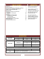
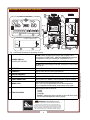
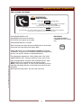
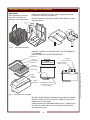
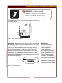
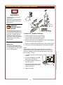
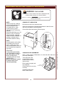
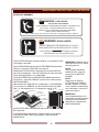
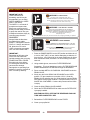
371
WELLS BLOOMFIELD, LLC
2 ERIK CIRCLE, P. O. Box 280 Verdi, NV 89439
telephone: 775-689-5703
fax: 775-689-5976
www.wellsbloomfield.com
OPERATION MANUAL
OPEN FRYPOT GAS
FRYER with AUTO-LIFT
MODEL
WFGA-60FS
WITH OR WITHOUT
OPTIONAL FILTER WAND
Includes
INSTALLATION
USE & CARE
Model WFGA-60FS
FOR YOUR SAFETY
Do not store gasoline or other flammable liquids
in the vicinity of this or any other appliance.
WARNING:
Improper installation, adjustment, alteration, service or maintenance can
cause property damage, injury or death. Read the installation and operating
instructions thoroughly before installing, using or servicing this equipment.
IMPORTANT: DO NOT DISCARD THIS MANUAL
This manual is considered to be part of the appliance and is to be given to the OWNER or
MANAGER of the restaurant, or to the person responsible for TRAINING OPERATORS of
this appliance. Additional manuals are available from your WELLS DEALER.
THIS MANUAL MUST BE READ AND UNDERSTOOD BY ALL PERSONS USING OR
INSTALLING THIS APPLIANCE. Contact your WELLS DEALER if you have any
questions concerning installation, operation or maintenance of this equipment.
PRINTED IN UNITED STATES OF AMERICA
p/n 301098 Rev. D ECN-13378
M371
071030
cps
LIMITED WARRANTY STATEMENT
Unless otherwise specified, all commercial cooking
equipment manufactured by WELLS BLOOMFIELD, LLC is
warranted against defects in materials and workmanship for
a period of one year from the date of original installation or
18 months from the date of shipment from our factory,
whichever comes first, and is for the benefit of the original
purchaser only.
THIS WARRANTY IS THE COMPLETE AND ONLY
WARRANTY, EXPRESSED OR IMPLIED IN LAW OR IN
FACT, INCLUDING BUT NOT LIMITED TO, WARRANTIES
OF MERCHANTABILITY OR FITNESS FOR ANY
PARTICULAR PURPOSE, AND/OR FOR DIRECT,
INDIRECT OR CONSEQUENTIAL DAMAGES IN
CONNECTION WITH WELLS BLOOMFIELD PRODUCTS.
This warranty is void if it is determined that, upon inspection
by an authorized service agency, the equipment has been
modified, misused, misapplied, improperly installed, or
damaged in transit or by fire, flood or act of God. It also
does not apply if the serial nameplate has been removed, or
if service is performed by unauthorized personnel. The
prices charged by Wells Bloomfield for its products are
based upon the limitations in this warranty. Seller’s
obligation under this warranty is limited to the repair of
defects without charge by a Wells Bloomfield factory
authorized service agency or one of its sub-service
agencies. This service will be provided on customer’s
premises for non-portable models. Portable models (a
device with a cord and plug) must be taken or shipped to
the closest authorized service agency, transportation
charges prepaid, for service. In addition to restrictions
contained in this warranty, specific limitations are shown in
the Service Policy and Procedure Guide. Wells Bloomfield
authorized service agencies are located in principal cities.
This warranty is valid in the United States and Canada and
void elsewhere. Please consult your classified telephone
directory, your foodservice equipment dealer or contact:
Service Department, Wells Bloomfield, LLC
P.O. Box 280, Verdi, Nevada 89439
phone (775) 689-5707 or fax (775) 689-5976
for information and other details concerning warranty.
SERVICE POLICY AND PROCEDURE GUIDE and ADDITIONAL WARRANTY EXCLUSIONS
1.
2.
3.
4.
6.
cleaning schedules, are customer responsibility. Those
miscellaneous adjustments noted are customer
responsibility. Proper attention to preventative
maintenance and scheduled maintenance procedures
will prolong the life of the appliance.
7. Travel mileage is limited to sixty (60) miles from an
Authorized Service Agency or one of its sub-service
agencies.
8. All labor shall be performed during regular working
hours. Overtime premium will be charged to the buyer.
9. All genuine Wells replacement parts are warranted for
ninety (90) days from date of purchase on nonwarranty equipment. This parts warranty is limited only
to replacement of the defective part(s). Any use of
non-genuine Wells parts completely voids any
warranty.
10. Installation, labor, and job check-outs are not
considered warranty and are thus not covered by this
warranty.
11. Charges incurred by delays, waiting time or operating
restrictions that hinder the service technician’s ability to
perform service are not covered by warranty. This
includes institutional and correctional facilities.
SHIPPING DAMAGE CLAIM PROCEDURE
NOTE: For your protection, please note that equipment in
this shipment was carefully inspected and packaged by
skilled personnel before leaving the factory. Upon
acceptance of this shipment, the transportation company
assumes full responsibility for its safe delivery.
IF SHIPMENT ARRIVES DAMAGED:
1. VISIBLE LOSS OR DAMAGE: Be certain that any
visible loss or damage is noted on the freight bill or
express receipt, and that the note of loss or damage is
signed by the delivery person.
2. FILE CLAIM FOR DAMAGE IMMEDIATELY:
Regardless of the extent of the damage.
3.
CONCEALED LOSS OR DAMAGE: if damage is
unnoticed until the merchandise is unpacked, notify the
transportation company or carrier immediately, and file
“CONCEALED DAMAGE” claim with them. This
should be done within fifteen (15) days from the date
the delivery was made to you. Be sure to retain the
container for inspection.
Wells Bloomfield cannot assume liability for damage or loss
incurred in transit. We will, however, at your request, supply
you with the necessary documents to support your claim.
xi
371 301098 OpManual for WFGA-60FS Gas Fryer
5.
Resetting of safety thermostats, circuit breakers, over
load protectors, and/or fuse replacements are not
covered by this warranty unless warranted conditions
are the cause.
All problems due to operation at voltages or phase
other than specified on equipment nameplates are
not covered by this warranty.
Conversion to correct voltage and/or phase must be
the customer’s responsibility.
All problems due to electrical connections not made
in accordance with electrical code requirements
and wiring diagrams supplied with the equipment are
not covered by this warranty.
Replacement of items subject to normal wear, to
include such items as knobs, light bulbs; and, normal
maintenance functions including adjustments of
thermostats, adjustment of micro switches and
replacement of fuses and indicating lights are not
covered by warranty.
Damage to electrical cords and/or plug due to exposure
to excessive heat are not covered by this warranty.
Full use, care, and maintenance instructions supplied
with each machine. Noted maintenance and
preventative maintenance items, such as servicing and
INTRODUCTION
TABLE OF CONTENTS
371 301098 OpManual for WFGA-60FS Gas Fryer
WARRANTY
SPECIFICATIONS
WFGA-60FS FEATURES & OPERATING CONTROLS
PRECAUTIONS & GENERAL INFORMATION
AGENCY LISTING INFORMATION
INSTALLATION
PREPARATION PRIOR TO OPERATION
OPERATION
OPTIONAL FILTER WAND
CLEANING
MAINTENANCE INSTRUCTIONS
CRADLE LIFT & ROLLERS
FILTER SYSTEM
DISCARDING USED OIL
TROUBLESHOOTING SUGGESTIONS
PARTS & SERVICE
CUSTOMER SERVICE DATA
xi
1
2
4
5
6
9
13
17
22
Thank You for purchasing this
Wells Bloomfield appliance.
Proper installation, professional
operation and consistent
maintenance of this appliance will
ensure that it gives you the very
best performance and a long,
economical service life.
This manual contains the
information needed to properly
install this appliance, and to use
and care for the appliance in a
manner which will ensure its
optimum performance.
24
25
29
30
31
31
SPECIFICATIONS
DIMENSIONS
CAPACITIES
Wide
Deep
High
18.19”
38.25”
47.44”
Lbs.
Kg.
Cooking Oil
(Liquid Shortening Only)
60
27
Chicken (Fresh)
30
13
Chicken (Frozen)
25
11
POWER REQUIREMENTS
VOLTAGE
FUEL
120VAC Single Phase Only
5 amps
Natural Gas (3.5” W.C.) field convertible to
LP/Propane (10” W.C.) to be performed by a qualified technician only.
1
FEATURES & OPERATING CONTROLS
11
UPPER CONTROL PANEL
FRONT VIEW
BACK VIEW
14
12
WELLS
2
5
4
3
6
15
1
16
FRYER
TIME
OFF
TEMP
HEAT
READY
MANUAL
FILTER
23
1
2
3
5
4
6
MANUAL
7
PAUSE
CLEAN
STANDBY
BASKET
FILTER
17
7
8
18
19
LOWER CONTROL PANEL
20
21
HI-LIMIT
22
RESET
13
9
10
Fig. 1 WFGA-60FS Features & Operating Controls
1
POWER SWITCH
(FRYER-OFF-FILTER)
FRYER position energizes the FRYER and POWER LIGHT;
de-energizes FILTER PUMP. HEATING ELEMENTS energized
and regulate to setting on CONTROL THERMOSTAT (8).
OFF position de-energized FRYER and FILTER PUMP.
FILTER position de-energizes FRYER; energizes FILTER PUMP
SWITCH (6).
TIME KEY
Used to check and set menu times
3
TEMP KEY
Used to check and set cooking temperature
4
DIGITAL READOUT
LED display of various data and functions
5
UP ARROW KEY
Used to raise FRY BASKET and to increase program settings
6
DOWN ARROW KEY
Used to lower FRY BASKET and to decrease program settings
7
MENU KEYS
Used to start a menu time/temp cook cycle
Keys 1 thru 6 are programmable for time and temperature
Key 7 is available for individually set time/temp cook cycles
FUNCTION KEYS
Used to perform the functions of:
PAUSE
CLEAN
STANDBY
BASKET (raise/lower when used with up arrow & down arrow)
FILTER (acknowledgement warning signal)
8
WARNING
WARNING:
FIRE HAZARD / HOT OIL
The HI-LIMIT THERMOSTAT is a FIRE PROTECTION DEVICE.
If tripping persists, clean debris from the space between the
hi-limit bulb and the element to enhance oil flow and facilitate reset.
Otherwise, contact your authorized Wells Service Agent for repairs.
DO NOT ATTEMPT TO BYPASS OR HOLD IN THE BUTTON OF
THE HI-LIMIT THERMOSTAT. A SERIOUS FIRE MAY RESULT.
2
371 301098 OpManual for WFGA-60FS Gas Fryer
2
FEATURES & OPERATING CONTROLS (continued)
371 301098 OpManual for WFGA-60FS Gas Fryer
9
HI-LIMIT THERMOSTAT
Provides over-temperature protection by de-energizing HEATING
ELEMENTS should oil temperature exceed factory pre-set limits.
10 SONALERT
Audible alarm to signal end of cook cycle and other programmed
functions
11 LIFT CRADLE
Raises and lowers FRY BASKET.
12 FRY BASKET
Sits on the LIFT CRADLE and holds product to be cooked.
Raised and lowered by the LIFT CRADLE.
13 OIL FILTER RESERVOIR
Holds the filter element. Holds oil during filtering cycle.
14 EXHAUST FLUE
Twin flues. Hot flue gases exit here.
15 LIFT MOTOR
Raises / lowers LIFT CRADLE. Accessible for lubrication
through the access plate in back panel.
16 VENTILATION SLOT
Provides air inlet for COOLING FAN inside CONTROL
PANEL.NEVER ALLOW WATER TO GET INTO THIS SLOT.
FILTER PUMP MOTOR RESET
17
BUTTON
The FILTER PUMP MOTOR is equipped with an over-heating
protection device. RESET must be performed manually. Allow
the motor to cool for approx. 15 min., then firmly press the red
button on the back of the motor until it “clicks”.
18 BURNER ASSEMBLY
Two assemblies; comprised of orifice, shutter, burner and ignitor.
19 DRAIN VALVE OVALHANDLE
Opens and closes the DRAIN VALVE.
To OPEN, turn the handle counterclockwise (to vertical).
To CLOSE, turn the handle clockwise (to horizontal).
20 GAS SHUT-OFF VALVES
Two valves, one located behind each gas control valve. Allow
isolation of either burner circuit.
21 GAS CONNECTION
Gas supply connects here.
22 POWER CORD
115V 15Amp, NEMA 5-15P
23 DATA PLATE
Identifies the appliance manufacturer, model and serial number;
also gives electrical ratings, gas ratings.
W1
W4
W2
W3
Fig. 2 Optional Wand
11
For units equipped with OPTIONAL FILTER WAND
W1 BURNER INTERLOCK SWITCH Disables burners any time drain valve is not closed.
W2 3-WAY VALVE HANDLE
W3
QUICK DISCONNECT MALE
FITTING
W4 FILTER WAND
HORIZONTAL directs output of filter pump to filter wand.
VERTICAL directs output of fliter pump to frypot.
Filter wand connects to this fitting.
Used to wash down sides of frypot, or to direct oil to disposal
container.
3
PRECAUTIONS AND GENERAL INFORMATION
DANGER:
BURN
HAZARD
Cooking oil in this appliance
operates at very high
temperatures. Contact with
hot oil can cause severe
injury or death. Wear
appropriate heat-protective
clothing when operating or
servicing this appliance.
Never attempt to open the
frypot if the pressure gauge
reads anything other than
“zero” (0) psi.
WARNING:
SLIP AND FALL
HAZARD
Spilled cooking oil is very
slippery and can cause falls.
Clean up oil spills promptly.
CAUTION:
BURN HAZARD
This appliance is intended for use in commercial establishments
only.
This appliance is intended to prepare food for human consumption.
No other use is recommended or authorized by the manufacturer or
its agents.
DO NOT open any panel that requires the use of tools for access.
Live electric circuits may be exposed by opening such panels.
Opening access panels must be performed by an Authorized Service
Agent only.
DO NOT operate this fryer unless the associated ventilation and
exhaust extraction systems are operating propery.
DO NOT obstruct combustion air for this fryer. DO NOT obstruct the
exhaust flues at the rear of the fryer. Do not store anything closer than
6” from the sides or front of this fryer.
This appliance is equipped with an oil filtration system designed to filter
hot liquid shortening only. Water, cleaning agents and/or other liquids
will contaminate the oil and may damage the filter pump.
Operators of this appliance must be familiar with the appliance use,
limitations and associated restrictions. Operating instructions must be
read and understood by all persons using or installing this appliance.
Cleanliness of this appliance is essential to good sanitation. Read and
follow all included cleaning instructions and schedules to ensure the
safety of the food product.
HEALTH
HAZARD
DO NOT store flammable or combustible materials on, in or near this
fryer.
Old cooking oil can be a
breeding ground for bacteria.
Clean and sanitize exterior
surfaces of fryer regularly.
Cooking oil will be very hot when in use. Contact will cause severe
injury, and can cause blindness or death. Wear appropriate heatprotective clothing when operating or servicing this appliance.
This appliance must be operated with the supplied legs and casters
properly installed
The technical content of this manual, including any parts breakdown
illustrations and/or adjustment procedures, is intended for use by
qualified technical personnel only.
Any procedure which requires the use of tools must be performed by a
qualified technician.
This manual is considered to be a permanent part of the appliance.
This manual and all supplied instructions, diagrams, schematics, parts
breakdown illustrations, notices and labels must remain with the
appliance if it is sold or moved to another location.
4
371 301098 OpManual for WFGA-60FS Gas Fryer
CAUTION:
DO NOT submerge any part of this appliance in water unless
specifically instructed to do so. This appliance is not jet stream
approved. DO NOT direct water jet or steam jet at this appliance,
nor at any control. DO NOT splash or pour water on, in or over any
controls. DO NOT wash area around this appliance with water jet.
Any part which has become wet must be thoroughly dried before use.
Exposed surfaces can be hot
to the touch and may cause
burns.
AGENCY LISTING INFORMATION
This appliance conforms to NSF Standard 4 for sanitation only if
installed in accordance with the supplied Installation Instructions and
maintained according to the instructions in this manual.
STD 4
This appliance meets ANSI Z.83.11 specifications for gas-fired food
service equipment.
371 301098 OpManual for WFGA-60FS Gas Fryer
This appliance is Canadian Standards Association design certified for
gas operation
5
INSTALLATION
NOTE: DO NOT discard
the carton or other packing
materials until you have
inspected the appliance for
hidden damage and tested it
for proper operation.
Refer to SHIPPING DAMAGE
CLAIM PROCEDURE on the
inside front cover of this
manual.
WARNING:
FIRE HAZARD
Do not store gasoline or
any other flammable or
combustible material near this
appliance.
The area where the fryer is
installed must be kept clear of
combustibles and flammables.
This includes mops, rags,
grease, wrapping paper and
electric cords.
UNPACKING & INSPECTION
Carefully remove the appliance from the carton. Remove all
protective plastic film, packing materials and accessories from the
appliance before connecting performing any installation procedure.
Carefully read all instructions in this manual and the Installation
Instruction Sheet packed with the appliance before starting any
installation.
Read and understand all labels and diagrams attached to the
appliance.
Carefully account for all components and accessories before
discarding packing materials. Store all accessories in a convenient
place for later use.
COMPONENTS
1 ea.
FILTER RESERVOIR
1 ea.
FILTER LEAF
4 ea.
OIL FILTER SUCTION TUBE O-RINGS
1 ea.
LIFT CRADLE
1 ea.
FRY BASKET
ACCESSORIES
1 ea.
LITERATURE PACKAGE
1 pk.
FILTER POWDER
2 ea.
HIGH TEMPERATURE BRUSHES
1 ea.
CLEANOUT DOWEL (wood rod)
Installation and startup must
be performed by a Wells
Manufacturing Authorized
Service Agency.
SETUP
IMPORTANT:
Certain jurisdictions require
fryers to be restrained with a
TETHER or other approved
restraint device. It is the
responsibility of the installer
to check with the AUTHORITY
HAVING JURISDICTION in
order to ascertain the applicability
of this requirement to
THIS SPECIFIC INSTALLATION.
Certain local or state codes require fryers to be restrained with a tether
or other approved restraint device. It is the responsibility of the installer
to check with the authority having jurisdiction, in order to ascertain the
applicability of this requirement to this specific fryer installation.
Installer must complete the
WARRANTY REGISTRATION
and FRYER CHECKOUT
form, and record the details of
the particular installation on
the CUSTOMER SERVICE
DATA form in this manual.
DO NOT obstruct the flow of the two exhaust flues (item 14) at the
top rear of the fryer. It is especially critical that gas supply piping and
electrical supply cord and/or receptacle be routed away from the path
of the hot combustion fumes.
It is the responsibility of the installer to verify that this fryer installation is
in compliance with local code authorities and with the specifications
listed in this manual.
LEVELING: Verify that the fryer sits firmly ON BOTH CASTERS AND
ON BOTH LEGS. With a spirit level, check that the fryer is level frontto-back and side-to-side. With the adjustable legs, adjust as required
to level the fryer.
This fryer must be installed and operated under a ventilation hood
conforming to all applicable local codes. Combustion fumes must be
vented in accordance with local codes.
Cooking and cleaning functions require unobstructed access. The
frypot, control panel and front access panel must be maintained free
from obstructions. The rear access panel must be accessible for
maintenance.
6
371 301098 OpManual for WFGA-60FS Gas Fryer
Setup the FRYER only on a firm, level surface. Clearances from all
combustible and non-combustible construction is 1” minimum. The
area around the fryer must be kept clear of combustibles.
INSTALLATION (continued)
GAS VALVE
VENTILLATION REQUIREMENTS
A single WFGA-60FS gas-fired fryer requires a minimum of 700 cubic
feet per hour (12 CFM) make-up air. The ventilation for the kitchen
must have sufficient capacity to prevent a negative-pressure condition.
DO NOT obstruct or restrict ventilation and make-up air required to
support combustion.
OPEN
CLOSED
Fig. 3 Gas Shut-Off Valves
KEEP THIS AREA CLEAR
14. EXHAUST GAS FLUE
FRYPOT
16. COOLING SLOT
UPPER CONTROL PANEL
LIFT MOTOR
ACCESS
LOWER CONTROL PANEL
23. DATA PLATE
BURNER ASSEMBLIES
FRONT ACCESS DOOR
GAS VALVES
23. GAS CONNECTION
22. ELECTRICAL
CONNECTION
FRONT VIEW
BACK VIEW
PLUMBING INSTALLATION
FIRE AND EXPLOSION HAZARD
371 301098 OpManual for WFGA-60FS Gas Fryer
GAS CONNECTIONS AND GAS ADJUSTMENTS MUST BE MADE BY
A LICENSED PLUMBER, CERTIFIED IN GAS INSTALLATION.
A gas explosion will cause death or serious injury
The installation of this fryer must conform to local codes. In the
absence of local codes, the installation of this fryer must conform with
the National Fuel Gas Code (ANSI Z223.1). In Canada, the National
Gas Installation Code (CAN/CGAB149.2) is applicable.
In any instance where gas supply pressure is in excess of 15” water
pressure (1/2 psi or 3.45kP), the fryer must be isolated from the supply
piping by closing its two individual manual shut-off valves (see fig. 3).
IMPORTANT: Failure to isolate the fryer from excessive pressure will
damage the gas valves and allow raw gas to leak into the room.
This fryer is orificed at the factory for natural gas at a pressure of 3.5” of
water column. The installed orifice is suitable for use at -280 to 2999
feet (-85 to 914 meters) elevation. It is the responsibility of the installer
to install the factory recommended orifice and pressure regulator kit
suitable for the fuel type and elevation at the final installation site.
The red tag (p/n 301217) attached to the gas connection provides
pressure settings and part numbers for conversion kits applicable to
various fuels and altitudes. (See fig.4 below)
7
Fig. 4 Fuel and Altitude
Conversion Tag
NOTE: Failure to install
proper orifices can burn
cooking oil and cause
potential burner and flue
system failure. Damaged
caused by improper orifice
installation is NOT covered
by warranty.
IMPORTANT:
Conversion for fuel and/or
altitude must be performed by
a licensed plumber certified in
gas installation only.
INSTALLATION (continued)
CAUTION:
ELECTRIC SHOCK
HAZARD
The grounding prong of the
electrical power cord is part of
a system designed to protect
you from injury in the event of
an electrical short.
DO NOT CUT OR REMOVE
THE GROUNDING PRONG
FROM THE PLUG.
Ungrounded electrical
equipment cause personal
injury and property damage.
ELECTRICAL INSTALLATION
1. Fryer electrical diagram and troubleshooting schematic are
located on the inside of the fryer door.
2. The fryer is equipped with a three-prong grounding plug
(NEMA 15-5P) for your protection against shock hazard. The fryer
must be plugged directly into a properly grounded three-prong
receptacle (NEMA 15-5R).
3. The installation of this fryer must conform to local codes. In the
absence of local codes, the installation of this fryer must conform
with the National Electrical Code (ANSI Z223.1).
In Canada, CSA C22.2 is applicable.
4. Because the fryer draws less than 8 amps, two fryers may be
plugged into the same 15 amp circuit if required.
371 301098 OpManual for WFGA-60FS Gas Fryer
8
PREPARATION PRIOR TO OPERATION
PRE-CLEANING PROCEDURE
WARNING
WARNING:
BURN HAZARD
USE THE CLEAN BUTTON ONLY
USE ONLY LOW-FOAMING COMMERCIAL FRYER CLEANSER.
CAREFULLY FOLLOW CLEANSER
CLEANING INSTRUCTIONS AND WARNINGS
DO NOT LEAVE FRYER UNATTENDED WHILE BOILING OUT FRYPOT.
BE PREPARED TO TURN POWER SWITCH OFF SHOULD WATER BEGIN FOAMING
Boiling water can splatter and may cause serious injury
Press POWER SWITCH OFF.
IMPORTANT:
Use a LOW-FOAMING
COMMERCIAL fryer cleanser
only.
Close DRAIN VALVE (lever horizontal).
Fill FRYPOT with 4 gallons of cold water.
Press POWER SWITCH to FRYER.
Wait 10 seconds, then press and hold CLEAN button for six seconds.
A beep will sound and readout will display “BOIL”.
Slowly add and stir in the LOW FOAMING COMMERCIAL FRYER
CLEANSER. Using the HIGH TEMPERATURE BRUSH supplied with
the fryer, stir until the cleanser is completely dissolved.
371 301098 OpManual for WFGA-60FS Gas Fryer
Time displayed is elapsed time. When display reads “1:30”, press
POWER SWITCH OFF. Allow the solution to cool to 120ºF or less.
Place a suitable METAL container under the DRAIN VALVE. Open
DRAIN VALVE (lever vertical) to drain the cleaning solution.
NOTE: Drain no more than 4” at a time into the container to prevent
splashing and spilling. Dispose of used solution as required by local
ordinances.
Rinse frypot with clean water. Dry with a soft clean cloth.
9
CLEAN
PREPARATION PRIOR TO OPERATION (continued)
IMPORTANT:
Serious damage to the frypot
will result if the rollers are
missing or do not rotate freely.
Examine the CRADLE ROLLERS. Adjust or tighten as required.
Lubricate the rollers with vegetable oil.
DO NOT operate the fryer unless CRADLE ROLLERS are in place
and rotating freely.
RETAINING NUT
ROLLER
LE
AD
R
TC
LIF
LIFT ROD
OT
PIV
Fig. 5
Lift Cradle Assembly
Install LIFT CRADLE onto CRADLE PIVOT. Set FRY BASKET on
LIFT CRADLE.
Install FILTER LEAF into FILTER RESERVOIR.
FILTER RAIL “A”
UPPER
FILTER SCREEN
RESERVOIR
ASSEMBLY
CROSS-SECTION VIEW
SEPARATOR
“O” RING IN
“O” RING GROOVE
STORAGE FOR 3
SPARE “O” RINGS
LOWER
FILTER SCREEN
FILTER RAIL “B”
“O” RING
SPARE
“O” RINGS
FILTER
RESERVOIR
Fig. 6
ASSEMBLED FILTER LEAF
(spout with O-RING inserts
into drain opening)
Filter Reservoir Assembly
SUCTION TUBE O-RINGS are shipped from the factory installed on
SUCTION TUBE; Examine to verify one O-RING is in the groove
closest to the end of the tube.
Install assembled FILTER RESERVOIR into fryer. O-RING for the
filter reservoir suction tube, and up to three spare O-RINGS, are
stored as shown above.
10
371 301098 OpManual for WFGA-60FS Gas Fryer
Note: “O” RING
PREPARATION PRIOR TO OPERATION (continued)
WARNING
WARNING:
SLIP/FALL HAZARD
CLOSE DRAIN VALVE BEFORE FILLING WITH OIL.
Unless drain valve is closed, oil poured into kettle will drain into
reservoir or onto the floor. Oil spill may occur.
Death or serious injury may result from slipping and falling in spilled oil.
Close DRAIN VALVE (item 19) by turning the handle to the horizontal
(CLOSED) position.
19
CLOSED
OPEN
371 301098 OpManual for WFGA-60FS Gas Fryer
Fig. 7
Drain Valve Operation
IMPORTANT: Remember to fill the fryer to the COLD OIL LINE with
fresh shortening prior to turning the POWER SWITCH to the FRYER
position. Energizing the fryer without oil covering the elements will
cause serious damage. Damage caused by operating the fryer
without oil covering the elements is not covered by warranty.
Fill FRYPOT to the COLD OIL LINE in the FRYPOT with room
temperature commercial-quality LIQUID SHORTENING. This
requires 55lbs. of liquid shortening for non-solid shortening melt
optioned fryers, and either 55 lb. of liquid or solid shortening for fryers
with SOLID SHORTENING MELT OPTION. Solid shortening should
be packed around elements.
FILL TO THIS LINE WITH COLD OIL
Fig. 8
COLD OIL LINE
Oil Level Indicator
11
IMPORTANT:
This fryer is designed for
LIQUID SHORTENING ONLY.
DO NOT USE SOLID
SHORTENING.
DO NOT USE LARD.
Solid shortening will solidify in
the FILTER RESERVOIR and
FILTER PUMP. This condition
will render the filter system
inoperable. Do not attempt to
pump shortening unless it is
liquid shortening or shortening
melted to the liquid state.
Damage caused to attempts to
pump anything other than
shortening in the liquid state is
not covered under warranty.
PREPARATION PRIOR TO OPERATION (continued)
CHECK CONTROLS FOR PROPER OPERATION
Refer to Operating Instructions, page 13.
NOTE: This fryer is equipped with two separate auto-ignition burner
control systems.
On startup, each ignition system will try three times to prove its
associated burner flame. Failure to prove flame will result in
shut-down of that burner circuit. Pressing the POWER SWITCH to
OFF, then back to FRYER will reset the fryer (and make three more
tries).
The fryer may be operated safely (at reduced capacity) with only one
burner operational.
WARNING
WARNING:
OIL SPLATTER HAZARD
The weight of product that can safely be cooked in this pressure fryer
will vary with oil level, product moisture content and oil temperature.
FAILURE TO DETERMINE THE SAFE WEIGHT OF PRODUCT
WILL RESULT IN HOT OIL RELEASE FROM THE FRYER
HOT OIL WILL CAUSE SEVERE BURNS ON CONTACT
Death or serious injury may result from slipping and falling in spilled oil.
DETERMINE MAXIMUM LOAD WEIGHT:
For operational safety, it is very important to determine the maximum
load weight for the specific operation. This can be accomplished by
starting out with small loads and gradually increasing to the largest
load size that will allow a cook cycle to be completed without oil
foaming out of the FRYPOT.
371 301098 OpManual for WFGA-60FS Gas Fryer
IMPORTANT:
For operational safety it is
important to determine the
maximum load weight for the
specific operation:
• Start with small loads
• Gradually increase load
size
• Determine the largest load
that will allow a full cook
cycle without oil foaming
out of the frypot.
• Post the maximum load in a
conspicuous spot near the
fryer.
12
OPERATION
PROGRAMMING KEY FUNCTIONS
2
CAUTION:
BURN HAZARD
6
5
4
3
Hot oil can cause serious burns
on contact. Wear appropriate
protective clothing when using
this fryer.
1
FRYER
TIME
OFF
TEMP
HEAT
READY
MANUAL
FILTER
1
2
3
4
7
5
6
MANUAL
7
PAUSE
8a
CLEAN
STANDBY
8b
8c
BASKET
FILTER
8d
8e
Controller operation for solid
shortening melt optioned fryers
is essentially identical to the
operation of the standard solid
state controller. Important
differenced are noted in the
text.
As each control panel key is pressed, a “beep” will sound. Illuminated
indicator light for each key will light whenever that key is pressed, and
any time the function associated with that key is active.
FRYER - OFF - FILTER switch (item 1) allows the fryer to be placed
in a normal cook mode (FRYER), an oil-filtering mode (FILTER) or
turned OFF.
TIME key (item 2) controls time functions.
TEMP key (item 3) controls temperature functions. Data can be read
on the solid state READOUT (item 4).
HEAT indicator is lit whenever the burners are energized; READY
indicator is lit when cooking oil is at programmed temperature.
MANUAL indicator is lit whenever MENU key 7 is selected.
371 301098 OpManual for WFGA-60FS Gas Fryer
Arrow keys (item 5 & 6) control the basket lift (after pressing BASKET
key), and are used to scroll through program settings.
MENU keys (item 7) allow a choice of six (or seven) pre-programmed
time / temp settings.
BASKET
1
2
3
5
4
Suggestion: MENU keys 1 and 2 incorporate a feature that will
inform the operator when to “drop” wings and drumsticks during cook
cycle. “Drop” feature will allow you to cook breasts and thighs longer
than wings and drumsticks by sounding a beep, and displaying “DrOP”
on readout (item 4). Your fryer installer can program this feature
into your controller upon request.
1
6
MANUAL
7
2
Any selected MENU key can be cancelled by pressing and holding
for 3 seconds.
MENU key 7 is unprogrammed so that special or one-of-a-kind
product may be programmed any time:
With fryer is ON, press and hold TIME key and MENU 7 key
at the same time.
Press the UP or DOWN arrow key until the desired time is
displayed.
If this MANUAL feature is not desired, MENU key 7 may be
programmed in the identical fashion to MENU keys 1 thru 6.
13
MANUAL
7
MANUAL
OPERATION (continued)
IMPORTANT:
To program the controller for
cooking your product you must
first determine the cooking time
and temperature required to
cook the product.
Each MENU key may be
programmed for a different time
and temperature, depending
upon the requirements of each
menu item.
PROGRAM MENU TIMES AND TEMPERATURES
For solid shortening melt optioned fryers, make sure elements are
packed with 55 pounds of solid shortening. For all other fryers, make
sure FRYPOT is filled with room temperature liquid shortening to the
COLD OIL LEVEL line inscribed on inside of FRYPOT. Do not
over-fill or under-fill frypot. (See page 11.)
Set the POWER SWITCH (item 1) to FRYER. After 10 seconds,
It is the sole responsibility
of the end user to determine
the time and temperature
requirements of each menu
item, and to program each
MENU key to the determined
time and temperature in order
to insure completely and
safely cooked product.
IMPORTANT:
Be sure to record which MENU
key corresponds to which menu
item or product to be cooked.
readout will display “MLt” (during melt cycle of solid shortening melt
optioned fryers only) then “Pre-” “HEAt”, followed by the number of
the menu currently selected (indicator of selected menu key will be lit).
Press
to verify the programmed temperature setting of that menu.
Press any MENU key to change to that menu.
Enter PROGRAMMING mode by pressing and holding
+
for
three seconds, until a beep sounds and readout displays “Pro9”.
Program MENU key 1 for the pre-determined cook time by pressing
and holding
pressing
+
1
or
at the same time. Scroll to the desired time by
until desired time is displayed on readout.
Program MENU key 1 for the pre-determined cook temperature by
pressing and holding
temp by pressing
+
or
1
at the same time. Scroll to desired
until desired temperature is displayed on
Program MENU keys 2 thru 6 in the same manner.
MANUAL
7
can be programmed, or left as a MANUAL menu key.
NOTE: Only
MANUAL
7
can be programmed while another MENU is cooking.
Exit PROGRAMMING MODE by pressing and holding
one second. Readout will display “00:00” or “PrE-” “HEAt”.
14
+
for
371 301098 OpManual for WFGA-60FS Gas Fryer
readout. Range is 200ºF - 375ºF (93ºC - 191ºC).
OPERATION (continued)
USING FUNCTION KEYS
PAUSE Halts time countdown while any menu is running and readout displays
time remaining.
• Purpose: Allows the user to raise fry basket to inspect product in the
middle of a cook cycle. Time remaining is frozen until PAUSE key is
pressed again.
• To use: While a menu is running, press and hold PAUSE key for five
seconds, until a beep sounds and red indicator near key lights.
Raise the basket to inspect product by pressing the BASKET key and UP
arrow key.
Resume cooking product by pressing BASKET key and DOWN arrow key.
Resume time countdown by pressing PAUSE key again.
• To change the time remaining while in pause:
(a) This option uses the near-instant programming feature of MENU 7
(MANUAL) key. Press and hold TIME key plus the MENU 7 key at the
same time.
(b) Scroll in a new time remaining with the UP or DOWN arrow keys.
Release all keys.
Press and hold the lit MENU key for three seconds. Remaining time will
cancel and display will read “00:00”.
Lower fry basket by pressing BASKET key followed by DOWN arrow
key. Press the MANUAL (MENU 7) key. Time will now countdown from
new time programmed into key 7. Basket will rise at end of new time,
display reads “00:00”.
If the original menu time or temperature must be adjusted, see
programming
procedure, page 17.
371 301098 OpManual for WFGA-60FS Gas Fryer
CLEAN puts the fryer into the cleaning mode by setting the temperature to
approximately 200ºF (94ºC) (i.e. just below the boiling point of water).
To Use: See CLEANING INSTRUCTIONS, page 22.
STANDBY puts fryer into “sleep” mode for off-peak periods.
• Purpose: This economy function allows the oil temperature to cool to
275ºF (135ºC) when the fryer is not in use, but it is not desirable to turn the
fryer off.
• To use: While no menu is running and the display reads “00:00”, press and
hold STANDBY key until a “beep” sounds and the red indicator lights.
To resume cooking after being in standby mode: Press and hold STANDBY
until a “beep” sounds. Heating elements will be energized. Fryer is ready
for use when READY light is lit.
BASKET allows UP and DOWN arrow keys to raise or lower fry basket.
• To Use: Press and release BASKET key. Red indicators over the basket
key and UP arrow and DOWN arrow keys will light. Press and release
either arrow key. Selected arrow key indicator will light. All keys will be inactive for ten seconds during the raise/lower cycle.
Active only in pre-heat and pause modes, or when display reads “00:00”.
FILTER acknowledges filter alarm. The filter alarm is programmed to sound
after a pre-set number of cook cycles. This is factory pre-set to zero cycles.
Your fryer installer can alter the number of cycles upon request.
• To Use: When the cycle count reaches the pre-set number, a “beep” will
sound. Press and release FILTER key to cancel alarm and reset filter load
counter to “zero”.
See FILTERING OIL, page 26.
15
PAUSE
BASKET
+
+
MANUAL
7
CLEAN
STANDBY
BASKET
FILTER
OPERATION (continued)
CAUTION:
BURN HAZARD
Hot oil can cause serious burns
on contact. Wear appropriate
protective clothing when using
this fryer.
IMPORTANT:
Use the plastic-coated
HANDLES of the fry basket
to remove basket of cooked
product from LIFT CRADLE.
PRE-HEAT THE FRYER
Press any MENU key. If oil temperature has not reached
programmed temperature, readout will display “Pre-” “HEAt”, followed
by the menu key #, and HEAT indicator will light. When oil has
reached programmed temperature, READY indicator will light, a
“beep” will sound five times and readout will display “00:00”. Readout
will normally display time remaining. To display oil temperature of lit
menu item, press
.
TO COOK PRODUCT
Press a MENU key
1
2
3
4
5
6
MANUAL
7
for desired menu item.
When oil reaches programmed temperature for that MENU key,
READY light will glow, HEAT light will go dark and five “beeps” will
sound.
FROZEN PRODUCT: Set FRY BASKET on LIFT CRADLE in the
raised position. Load frozen product into BASKET. Lower BASKET
by pressing
BASKET
, then
. When basket is fully down, start timed
cycle by pressing appropriate MENU key. At the end of the timed
cycle, basket will raise automatically (and 10 second buzzer will
sound).
FRESH PRODUCT: Set empty BASKET on LIFT CRADLE in the
BASKET
, then
.
Manually drop each piece of fresh product into the hot oil just above
oil level to minimize splattering. ALWAYS USE PROTECTIVE
EQUIPMENT, SUCH AS INSULATED GLOVES, TO PROTECT
AGAINST BURNS FROM CONTACT WITH HOT OIL. For chicken,
drop thighs and breasts first, followed by drumsticks, then wings.
Start a timed cycle by pressing appropriate MENU key.
SUGGESTION: MENU keys 1 and 2 incorporate a feature that will
inform the operator when to “drop” the wings and drumsticks during
the cooking cycle. DROP feature will allow you to cook breasts and
thighs longer than wings and drumsticks by audibly beeping, and
displaying “DrOP ” on the readout. Your fryer installer can program
this feature into your controller upon request.
16
371 301098 OpManual for WFGA-60FS Gas Fryer
raised position. Lower BASKET by pressing
OPERATION - OPTIONAL FILTER WAND
FRYER OIL WAND
Wells p/n 23068 Fryer Oil Wand is used as a convenient method of
cleaning the sides of the frypot during filtering, and for draining oil
from the fryer for disposal.
The wand connects to the fryer with a positive shut-off
quick-disconnect fitting. The wand is powered by the fryer’s filter
pump, and draws oil from the filter reservoir.
DANGER:
BURN HAZARD
Contact with hot oil will cause
severe burns.
Always wear protective clothing
and heat resistant gloves when
operating the fryer, filtering the
oil or using the oil wand.
371 301098 OpManual for WFGA-60FS Gas Fryer
IMPORTANT:
Press the FRYER-OFF-FILTER
switch to the OFF position before
inserting or removing the wand.
17
OPERATION - OPTIONAL FILTER WAND (continued)
DANGER:
BURN HAZARD
Contact with hot oil will cause
severe burns.
Always wear protective clothing
and heat resistant gloves when
filtering the oil.
WARNING:
ELECTRIC SHOCK
HAZARD
All servicing requiring access to
non-insulated components must
be performed by qualified service
personnel. DO NOT open any
access panel that requires the
use of tools. Failure to heed this
warning may result in severe
electric shock.
FILTERING OIL - NORMAL OPERATION
1. Prepare the filter reservoir pan for filtering.
2. Turn the DRAIN VALVE HANDLE down to
open the drain and fill the filter reservoir.
3. Be sure the 3-WAY VALVE HANDLE is in the left-right position
to direct the pump output to the frypot.
IMPORTANT:
Be sure the 3-way valve in the
left-right position before pressing
the FRYER-OFF-FILTER switch
to the FILTER position.
4. Press the FRYER-OFF-FILTER switch to the FILTER position.
5. Filter as per instructions described in Fryer Operation Manual.
1. Turn the 3-way valve to the left-right
position.
2. Press the FRYER-OFF-FILTER
switch to the OFF position.
3. Wait approximately 3 minutes for
the motor to cool.
4. Press the red reset button on the
front end of the filter motor until it
“clicks” and locks in.
5. Resume operation.
18
371 301098 OpManual for WFGA-60FS Gas Fryer
NOTE:
If the FRYER-OFF-FILTER switch is pressed to the FILTER
position with the 3-way valve handle in the front-to-back position
(wand not installed), the filter pump will stall and then trip on the
internal safety. To reset:
OPERATION - OPTIONAL FILTER WAND (continued)
DANGER: BURN HAZARD
Contact with hot oil will cause severe burns. Always wear protective clothing and heat
resistant gloves when operating the fryer, filtering the oil or using the oil wand.
WARNING: ELECTRIC SHOCK HAZARD
All servicing requiring access to non-insulated components must be performed by
qualified service personnel. DO NOT open any access panel that requires the use of
tools. Failure to heed this warning may result in severe electric shock.
CAUTION: BURN HAZARD
Contact with hot oil may cause burns. DO NOT fill fryer beyond MAX OIL line on frypot.
For disposal of oil use only a container specifically designed for the disposal of hot oil.
DO NOT fill hot oil disposal container beyond MAX OIL line.
PRECAUTIONS AND GENERAL INFORMATION
The fryer oil wand accessory attachment is intended for use only
with Wells Mfg. Co. floor-standing fryers equipped with wand
attachment provisions.
The fryer oil wand accessory attachment is intended for use only
in commercial establishments where all operators are familiar
with its use, limitations and associated hazards.
371 301098 OpManual for WFGA-60FS Gas Fryer
Operator Instructions, including all warnings and precautions,
must be read and understood by all operators and users of this
fryer oil wand accessory attachment prior to use.
The fryer oil wand accessory attachment is designed and
intended for use to wash down the sides of the frypot of the fryer
to which the wand is attached, or to pump oil from that fryer into
a suitable hot oil disposal container. No other use of this fryer
oil wand accessory attachment is intended or authorized by
Wells Manufacturing Co. or its agents.
19
NOTE: This Operator Instruction is
considered to be a part of the fryer
appliance, and must remain with
the appliance if it is sold or moved
to a different location.
OPERATION - OPTIONAL FILTER WAND (continued)
DANGER:
BURN HAZARD
Contact with hot oil will cause
severe burns.
Always wear protective clothing
and heat resistant gloves when
using the oil wand.
IMPORTANT:
Be sure the wand is properly
installed, and that the discharge
nozzle of the oil wand is directed
either into the frypot, or into a
suitable hot oil disposal container,
before pressing the FRYER-OFFFILTER switch to the FILTER
position.
CAUTION:
BURN HAZARD
NOTE:
If the discharge from the nozzle is
not a steady stream, the filter is
clogged with breading and/or filter
powder:
a. Close the frypot drain valve
by turning the drain valve
handle to the up position.
When all oil is returned to
the frypot press the
FRYER-OFF-FILTER switch
to OFF.
b. Allow the filter reservoir to
cool. Refer to the Operation
Manual for instructions on
cleaning the filter and filter
reservoir.
1. If discarding oil, be sure a suitable hot oil disposal container
is available. Otherwise, prepare the filter reservoir pan for
filtering.
2. Turn the DRAIN VALVE HANDLE down to open the drain and
fill the filter reservoir.
3. Insert the wand fitting into the fryer fitting:
a. Slide the locking ring of the wand fitting fully toward the
hose.
b. Insert the wand fitting fully into the fryer fitting.
c. Allow the locking ring to spring forward.
d. Check to verify that the wand fitting is held securely by
pulling on the hose.
4. Turn the 3-WAY VALVE HANDLE clockwise to the front-to-rear
position to direct the pump output to the oil wand.
5. Direct the discharge nozzle of the oil wand into the frypot, or
into a suitable hot oil disposal container. DO NOT fill beyond
the MAX OIL line.
6. Press the FRYER-OFF-FILTER switch to the FILTER position.
7. Wand may be used to wash down the sides of the frypot during
filtering, or to pump oil into a container for disposal.
8. At conclusion of use, press the FRYER-OFF-FILTER switch to
the OFF position, disconnect wand from fryer fitting and return
the handle of the 3-way valve to the left-right position.
9. Drain any remaining oil in the wand by pointing the discharge
nozzle of the wand down into the frypot or disposal container.
20
371 301098 OpManual for WFGA-60FS Gas Fryer
Contact with hot oil may cause
burns. DO NOT fill fryer beyond
MAX OIL line on frypot.
For disposal of oil, use only a
container specifically designed
for the disposal of hot oil.
DO NOT fill hot oil disposal
container beyond MAX OIL line.
USING THE OIL WAND - WASH OUT FRYPOT or DISCARD OIL
OPERATION - OPTIONAL FILTER WAND (continued)
DANGER:
BURN HAZARD
Contact with hot oil will cause
severe burns.
Always wear protective clothing
and heat resistant gloves when
operating the fryer.
CAUTION: BURN
HAZARD
RETURN FRYER TO NORMAL OPERATION AFTER USING THE
OIL WAND
1. After washing down the frypot, turn the DRAIN VALVE
HANDLE up to close the frypot drain.
IMPORTANT: Drain handle must be fully closed in order to
activate the heater safety switch. The drain handle must be
in the fully “up” position before fryer heating element can be
energized.
371 301098 OpManual for WFGA-60FS Gas Fryer
2. Be sure the 3-WAY VALVE HANDLE is returned to the
left-right position.
Press the FRYER-OFF-FILTER switch to the FILTER position.
When all oil has been returned to the frypot, press the
FRYER-OFF-FILTER switch to the FRYER position to resume
operation, or to the OFF position to shut down.
21
Overflow of hot oil may
cause burns. DO NOT fill fryer
beyond MAX OIL line on frypot.
IMPORTANT:
When refilling the frypot, be
sure the 3-way valve handle is
left-right, and the drain valve
handle is up before pressing the
FRYER-OFF-FILTER switch to
the FILTER position.
CLEANING INSTRUCTIONS
DANGER: BURN HAZARD
Contact with hot oil will cause severe burns. Allow the fryer to cool before cleaning.
Always wear protective clothing and heat resistant gloves when cleaning the fryer.
CAUTION:
PREPARATION
Press POWER SWITCH to OFF
Allow fryer to cool completely before cleaning
Disconnect fryer from electric power before
cleaning
FREQUENCY
Daily, or as needed
TOOLS
Mild Detergent, Non-abrasive cleanser
Soft Cloth or Sponge, Plastic Scouring Pad
ELECTRIC
SHOCK HAZARD
Disconnect fryer from electric
power before cleaning.
CAUTION:
BURN HAZARD
DAILY CLEANING
Allow fryer to cool completely
before cleaning.
IMPORTANT: DO NOT spill
or pour water into controls,
control panel or wiring.
IMPORTANT: DO NOT use
steel wool or abrasive
cleansers for cleaning the
fryer cabinet or frypot.
1. Press POWER SWITCH to OFF.
2. Remove FRY BASKET, LIFT CRADLE and FILTER RESERVOIR
ASSEMBLY.
IMPORTANT: Clean reservoir only when empty.
3. Allow the oil to cool to a safe temperature (120ºF or less).
4. Fry basket and lift cradle may be washed in a dishwasher, or with
warm water and mild detergent. Rinse thoroughly and dry
completely.
5. Clean FILTER RESERVOIR, FILTER LEAF in the dishwasher, or
use warm water with a mild detergent. Be sure all components are
thoroughly dry, then reassemble
6. Keep all exterior surfaces free from splashed grease by wiping with
a clean cloth dampened with warm water and mild detergent.
• Clean both sides of FRYPOT COVER.
• Clean side, front and accessible interior areas of cabinet.
• A non-abrasive detergent and plastic scouring pad may be
used for stubborn deposits.
• Dry with a soft clean cloth.
IMPORTANT: DO NOT use steel wool or abrasive cleansers
as these will damage the surface finish.
IMPORTANT: DO NOT spill or pour water into controls, control
panel or wiring. Damage to internal components will occur.
7. Reinstall LIFT CRADLE, FRY BASKET and FILTER RESERVOIR
ASSEMBLY.
Procedure is complete.
22
371 301098 OpManual for WFGA-60FS Gas Fryer
122 306626 OpManual for HDG-Series Griddles
122 306626 OpManual for HDG-Series Griddles
IMPORTANT: Be sure FILTER LEAF and inside of RESERVOIR
SUCTION TUBE are completely dry.
CLEANING INSTRUCTIONS (continued)
WARNING
WARNING:
BURN HAZARD
USE THE CLEAN BUTTON ONLY
USE ONLY LOW-FOAMING COMMERCIAL FRYER CLEANSER.
CAREFULLY FOLLOW CLEANSER
CLEANING INSTRUCTIONS AND WARNINGS
DO NOT LEAVE FRYER UNATTENDED WHILE BOILING OUT FRYPOT.
BE PREPARED TO TURN POWER SWITCH OFF SHOULD WATER BEGIN FOAMING
Boiling water can splatter and may cause serious injury
IMPORTANT:
Use a LOW-FOAMING
COMMERCIAL fryer cleanser
only.
CLEAN
371 301098 OpManual for WFGA-60FS Gas Fryer
371 301098 OpManual for WFGA-60FS Gas Fryer
371 301098 OpManual for WFGA-60FS Gas Fryer
IMPORTANT:
DO NOT press FRYER-OFFFILTER SWITCH to FILTER
with anything other than
shortening in the filter
reservoir. Water and/or
cleaning chemicals can:
• cause severe oil splatter
• damage the filter pump
• contaminate cooking oil
and food product.
PREPARATION
Drain oil from fryer before cleaning
FREQUENCY
Monthly, or as needed
TOOLS
Low-foaming commercial fryer cleanser
Metal disposal container
MONTHLY BOIL-OUT
1. Press POWER SWITCH OFF.
2. Close DRAIN VALVE (lever horizontal).
Fill FRYPOT with 4 gallons of cold water.
3. Press POWER SWITCH to FRYER.
Wait 10 seconds, then press and hold CLEAN button for six
seconds. A beep will sound and readout will display “BOIL”.
4. Slowly add and stir in the LOW FOAMING COMMERCIAL
FRYER CLEANSER. Using the HIGH TEMPERATURE BRUSH
supplied with the fryer, stir until the cleanser is completely
dissolved.
5. Time displayed is elapsed time. When display reads “1:30”, press
POWER SWITCH OFF. Allow the solution to cool to 120ºF or
less.
6. Place a suitable METAL container under the DRAIN VALVE.
Open DRAIN VALVE (lever vertical) to drain the cleaning solution.
NOTE: Drain no more than 4” at a time into the container to
prevent splashing and spilling. Dispose of used solution as
required by local ordinances.
7. Rinse frypot with clean water. Dry with a soft clean cloth.
Procedure is complete
23
MAINTENANCE INSTRUCTIONS - CRADLE LIFT AND ROLLERS
WARNING
WARNING: PINCH HAZARD
DISCONNECT FRYER FROM ELECTRIC POWER BEFORE
LUBRICATING CRADLE LIFT DRIVE SCREW
If power is not disconnected, lift motor may start unexpectedly,
causing serious injury
NOTE:
Failure to keep the cradle lift
screw properly lubricated will
result in premature wear
of the brass lift nut Wear
caused by lack of proper
lubrication is NOT covered by
warranty.
Recommended frequency is “as
required”, and, at a minimum,
every six months. Lubricate
cradle lift screw immediately if a
grinding or rubbing noise is
heard when basket is raising.
NOTE:
Smooth operation of the rollers
is essential to the life of the
frypot. If rollers do not turn
freely during operation, they will
soon wear grooves through the
frypot wall.
Disconnect the fryer from electrical power.
Open rear access panel. Coat exposed threads of cradle lift screw
with moly (molybdenum disulfide) grease.
Close access panel and restore electrical power.
CRADLE LIFT
DRIVE
SCREW
GREASE
THREADS
ACCESS
PANEL
BRASS
NUT
CRADLE
LIFT
DRIVE
MOTOR
CRADLE ROLLER ASSEMBLIES
DAILY: Wash cradle in a dishwasher or in a sink with warm water and
mild soap or detergent.
Thoroughly flush roller
bearings with hot water
(under a faucet or with a
spray nozzle).
Rinse cradle thoroughly and
dry completely.
Check rollers to be sure they
roll freely.
Check the bearing nuts.
KEEP THEM TIGHT!
24
ROLLER
RETAINING NUT
371 301098 OpManual for WFGA-60FS Gas Fryer
IMPORTANT:
IF ROLLERS ARE FROZEN
OR OTHERWISE FOUND TO
NOT SPIN FREELY AFTER
BEING THOROUGHLY
CLEANED, REPLACE THEM
IMMEDIATELY.
Wear to the FRYPOT caused
by frozen rollers is not
covered by warranty.
CRADLE LIFT LUBRICATION
MAINTENANCE INSTRUCTIONS - FILTER SYSTEM
FILTER LEAF ASSEMBLY
WARNING
WARNING:
BURN HAZARD
HOT OIL SPILL OR SPLATTER
DO NOT REMOVE FILTER RESERVOIR WHEN IT CONTAINS HOT OIL
HOT OIL WILL CAUSE SEVERE BURNS ON CONTACT
PROTECTIVE CLOTHING AND GLOVES MUST BE WORN
DURING THE FILTERING PROCESS
Death or serious injury may result from contact with, or slipping and falling in, spilled oil.
WARNING
WARNING: BURN HAZARD
DO NOT REMOVE FILTER RESERVOIR IF IT IS HOT.
WEAR INSULATED GLOVES OR ALLOW IT TO COOL.
Hot oil quickly heats reservoir. Touching hot reservoir
with bare hands can causing serious injury
Clean FILTER LEAF after each day’s filtration, or as needed to return
oil promptly to the kettle.
Open FRYER DOOR and slide the FILTER RESERVOIR forward to
remove it. Remove FILTER LEAF from reservoir.
371 301098 OpManual for WFGA-60FS Gas Fryer
Disassemble FILTER LEAF by separating the two side rails at the
joint with the straight pin. Clean all components in a sink with warm
water and mild detergent, or in a dishwasher.
Assemble SCREEN with the SEPARATOR installed between the
two screens. Verify that O-RING is in place on the suction tube on
BOTTOM SCREEN.
Slide screens into SIDE RAIL “B” (L-shaped pin). Hook SIDE RAIL
“A” over the pin on SIDERAIL “B” and work the screens into SIDE
RAIL “A” until straight pin on “A” is held by the “bump” on “B”.
TOP VIEW
FILTER RAIL “A”
STRAIGHT
PIN
SIDE VIEW
UPPER
FILTER SCREEN
IMPORTANT: Make sure all oil
is pumped into FRYPOT before
removing reservoir.
NOTE:
When properly assembled,
handle will point away from
suction tube on BOTTOM
SCREEN.
NOTE:
Inspect the “O” RING on
FILTER SUCTION TUBE for
damage. Replace “O” ring if it
is cut, cracked or scuffed using
one of the spare o- rings in the
suction tube groove.
IMPORTANT:
Avoid contaminating the oil or
food product by verifying that all
components of filter reservoir
assembly are completely dry
before reassembling.
SEPARATOR
LOWER
FILTER SCREEN
“L”-SHAPED
PIN
FILTER RAIL “B”
Install FILTER LEAF in RESERVOIR with suction tube firmly into
filter drain hole.
Install filter reservoir into the fryer. Make sure the “O” ring closest
to end of SUCTION TUBE is firmly seated in SUCTION LINE
RECEPTACLE.
25
MAINTENANCE - FILTER SYSTEM (continued)
FILTERING OIL
WARNING
WARNING: BURN HAZARD
BE ABSOLUTELY CERTAIN THAT NO WATER REMAINS
IN RESERVOIR OR SUCTION TUBE
WATER WILL BOIL VIOLENTLY IN CONTACT WITH HOT OIL
Boiling water can splatter hot oil and may cause serious injury
NOTE:
Oil should be at least 300ºF (149ºC) DO NOT attempt to filter cold oil.
DO NOT attempt to pump oil when less than 300ºF. Cold oil will not
pass through the filter paper. Filtering cold oil will result in the
premature failure of the filter pump. Damage as a result of pumping
cold oil IS NOT COVERED BY WARRANTY.
NOTE:
DO NOT store oil in the reservoir for any extended period, including
overnight.
IMPORTANT:
The filtration system in your Wells Fryer is designed to filter hot liquid
shortening ONLY. Water, cleaning agents or other liquids will
damage the filter pump and may contaminate the food product
Press POWER SWITCH (item 1) to FILTER. Pump motor will be
energized and heating elements are de-energized.
Reinstall reservoir, making sure the SUCTION TUBE is firmly seated
in the SUCTION RECEPTACLE.
Press FILTER PUMP SWITCH (item 8) to ON to start filter pump.
Slowly rotate DRAIN VALVE LEVER (item 11) to the vertical position.
Oil will drain from the frypot and into the reservoir. Filter pump will
draw oil through the filter leaf and return it to the frypot.
26
BURN HAZARD
Protective clothing and gloves
must be worn during the filtering
process
CAUTION
BURN HAZARD
Filter reservoir may be hot.
Wear insulated gloves, or
allow reservoir to cool,
before touching it.
IMPORTANT:
Filtering cooking oil helps to
ensure the quality of the food
product. Careful observation of
the finished food product will
help you determine the optimal
filtering frequency.
(Example: Filter the oil after
each six loads of fresh breaded
chicken)
FILTER POWDER absorbs
acids and many other
contaminants in the cooking oil,
allowing the oil to be used
longer before it must be
replaced. Wells Flavor Saver
Oil Filter Powder is available
from your Wells Equipment
Dealer or Authorized Service
Agent in a case of 45 packages
(p/n 22410).
371 301098 OpManual for WFGA-60FS Gas Fryer
Remove and examine filter reservoir:
• Verify that filter leaf is clean and properly installed.
• Verify that suction tuibe o-ring is in place and in good condition.
• Make absolutely certain that no water remains in bottom of
reservoir or in suction tube.
CAUTION
MAINTENANCE - FILTER SYSTEM (continued)
WARNING
WARNING:
BURN HAZARD
WEAR PROTECTIVE CLOTHING AND INSULATED GLOVES
WHEN CLEANING FRYPOT WITH HI-TEMP BRUSH AND WHEN
CLEARING DRAIN WITH WOOD CLEANOUT DOWEL.
Frypot and oil will be hot. Hot oil may splatter.
Contact with hot oil can cause serious injury
Carefully and slowly add the contents of one package of FILTER
POWDER to the oil in the frypot. Sprinkle filter powder onto surface
of the oil at point where it is being drawn down the drain.
Brush down sides and bottom of frypot using provided hi-temperature
brush. Loosen crumbs and other debris to flush them into reservoir.
Use the provided WOOD DOWEL to clear clogs in the frypot drain.
Push dowel down through drain hole in the front center of the frypot..
Rotate DRAIN VALVE LEVER (item 11) to the horizontal position
when filtering is complete,
Observe the oil returning to frypot. When bubbles appear, wait
approximately 15 seconds, then press FILTER PUMP SWITCH OFF.
371 301098 OpManual for WFGA-60FS Gas Fryer
Verify that all oil has been returned to frypot at end of filtering cycle.
Then, press POWER SWITCH to either:
a. FRYER position to resume cooking; or,
b. OFF position to service filter or shut-down fryer.
27
IMPORTANT:
DO NOT leave the fryer
unattended during the filtering
process. Continuously monitor
oil level in the reservoir to avoid
overflowing reservoir and
spilling oil on the floor.
Be prepared to turn the drain
valve lever clockwise to stop
or regulate the flow of oil.
IMPORTANT:
Verify that all oil has been
returned to frypot at end of
filtering cycle.
IMPORTANT:
Crumbs and other debris left
in the filter reservoir can
prevent filter leaf from sealing
completely. This will cause
incomplete filtration.
MAINTENANCE - DISCARDING USED OIL
IMPORTANT NOTE:
These instructions for
discarding used oil may be
disregarded if you are using
WELLS MOBILE OIL CADDY
WOC-1 (p/n 22470).
The WAOC-1 is a manual oil
pump/removal system that
allows you to pump used oil
directly into the caddy, and then
to pump the used oil into your
oil disposal container simply by
reversing pump direction.
BURN HAZARD
OIL MUST COOL TO BELOW 120ºF (49ºC)
BEFORE DRAINING OIL FROM FRYER FOR DISPOSAL
Normal operating temperature of the fryer is 375ºF (191ºC)
Contact with hot oil can cause serious injury
WARNING
WARNING:
SLIP AND FALL HAZARD
DO NOT USE FILTER RESERVOIR TO DISCARD OIL
USE A METAL CONTAINER TO COLLECT OIL FOR DISPOSAL
DO NOT FILL DISPOSAL CONTAINER MORE THAN ½ FULL
Do not leave fryer unattended when draining oil
Oil spills may occur
Death or serious injury may result from contact with, or slipping and falling in, spilled oil.
REMEMBER:
Always follow the directions
provided with the caddy.
WAOC-1 is designed to handle
COLD oil. Always, and without
fail, allow the oil to cool to
120ºF or less prior to pumping.
HOT OIL WILL BURN YOU!
IMPORTANT:
Remember to fill frypot to the
COLD OIL LINE with fresh
liquid shortening prior to turning
POWER SWITCH to FRYER
Energizing the fryer without
oil covering the elements will
cause serious damage.
Damage due to operating fryer
without oil covering elements is
NOT covered by warranty.
WARNING:
WARNING
WARNING
WARNING: BURN HAZARD
DO NOT REMOVE FILTER RESERVOIR IF IT IS HOT.
WEAR INSULATED GLOVES OR ALLOW IT TO COOL.
Hot oil quickly heats reservoir. Touching hot reservoir
with bare hands can causing serious injury
1. Press the POWER SWITCH to the OFF position and allow the oil
to cool to 120ºF (49ºC), or less, before attempting to drain the oil
from the fryer. All oil should be in the kettle Make sure all oil has
been returned to kettle, and there is no oil remaining in the filter
reservoir.
2. Using suitable gloves, remove the FILTER RESERVOIR.
Suggestion: This is an ideal time to run the FILTER RESERVOIR
and the disassembled FILTERLEAF through the dishwasher.
3. Place a suitable METAL OIL DISPOSAL CONTAINER under the
DRAIN VALVE.
5. Close the OVAL DRAIN VALVE HANDLE.
6. Check the FILTER RESERVOIR to make sure the FILTER LEAF
is properly installed.
MAKE ABSOLUTELY CERTAIN THE RESERVOIR PAN AND
TUBE ARE COMPLETELY DRY.
7. Reinstall the FILTER RESERVOIR into the FRYER.
8. Clean up any spilled oil.
28
371 301098 OpManual for WFGA-60FS Gas Fryer
4. Slowly turn the OVAL DRAIN VALVE HANDLE to the OPEN
position. Fill the container no more than 1/2 full. Close the
DRAIN VALVE and allow the oil to finish draining from the DRAIN
PIPE before removing the container. Dump the used oil into your
WASTE OIL CONTAINER. Continue this process until the kettle
is empty.
TROUBLESHOOTING
SYMPTOM
Fryer will not heat
Burners won’t light, or “pop” when igniting
371 301098 OpManual for WFGA-60FS Gas Fryer
Lift cradle will not lower
POSSIBLE CAUSE
SUGGESTED REMEDY
Unit disconnected from electric power
Reconnect to power
Check/reset circuit breaker
Menu temp not programmed or set too
low
Press TEMP key to check current
temperature. Program menu key for
desired temperature as required
Hi-Limit thermostat (item 9) tripped
Allow unit to cool, reset hi-limit
See page 3
Fryer in CLEAN mode
(Display reads BOIL)
Press power switch OFF, wait 10
seconds, press power switch to FRYER
Fryer in STANDBY mode
Press STANDBY key for three seconds
(beep will sound). Press and release
MENU key to resume cooking.
Drain not fully closed (filter wand option)
Be sure drain handle is fully closed
(drain safety switch made).
Internal damage
Contact your Authorized Wells Service
Agency for repairs
GAS SHUT-OFF VALVE(S) not fully ON
Verify that gas shut-off valves are in full
open position
Gas pressure not correct
Verify that gas pressure regulators are
are adjusted to the recommended
pressure.
MUST BE PERFORMED BY A
QUALIFIED TECHNICIAN.
Internal damage or internal component
mis-adjusted
Contact your Authorized Wells Service
Agency for repairs
Menu key not programmed for time, or
programmed to 00:00
Program menu key for desired time.
Be sure to press BASKET + DOWN to
lower basket.
Internal damage or mis-adjustment
Contact your Authorized Wells Service
Agency for repairs
PAUSE pressed
Be sure to press BASKET + DOWN to
lower basket. Press PAUSE when
basket is down to resume
Lift cradle not properly assembled to lift
rod
Properly assemble cradle pivot to lift rod
Internal damage or mis-adjustment
Contact your Authorized Wells Service
Agency for repairs
Lift cradle will not raise
CONTINUED ON PAGE 30
NOTE: There are no user serviceable
components in the fryer. In all cases of
damage or malfunction, contact your
Authorized Wells Service Agency for
repairs.
29
TROUBLESHOOTING (continued)
SYMPTOM
Filter pump will not run
Filter reservoir overflows
during filter cycle
POSSIBLE CAUSE
SUGGESTED REMEDY
Switches not set for filtering
Press power switch (item 1) to FILTER
Press pump filter switch (item 6) to ON
Pump overload (item 17) tripped
Reset overload. Press red button until it
“clicks” and stays locked in
Internal damage (pump overload trips
frequently)
Contact your Authorized Wells Service
Agency for repairs
Drain valve (item 19) not properly set
Oil level in reservoir must be monitored
at all times while filtering. Adjust flow by
opening or closing drain valve
Filter leaf surface clogged with crumbs or
other cooking debris
Turn drain valve OFF. When bubbles
begin appearing in frypot turn filter pump
switch OFF. Carefully slide reservoir out
12” and clear surface of filter leaf with
hi-temp brush or wooden dowel. Reinstall reservoir and resume filtering.
Filter leaf not properly assembled or not
properly installed
Reassemble filter leaf. Be sure o-ring is
in place, o-ring receptacle is clean and
filter leaf is properly installed in reservoir.
Filter leaf screen damaged
Replace filter leaf
Filter leaf o-ring damaged
Replace filter leaf o-ring
Suction tube not seated, allowing air to
enter system
When inserting filter reservoir be sure
suction tube is fully seated in suction line
receptacle.
Suction tube o-ring damaged
Replace suction tube o-ring
Internal damage
Contact your Authorized Wells Service
Agency for repairs
Does not filter completely
Filter pump won’t pump, or pumps air
when filtering
NOTE: There are no user serviceable
components in the fryer. In all cases of
damage or malfunction, contact your
Authorized Wells Service Agency for
repairs.
371 301098 OpManual for WFGA-60FS Gas Fryer
30
PARTS & SERVICE
DESCRIPTION
PART NO.
BASKET, FULL SIZE
BASKET, 1/2 SIZE
FLAVOR-SAVER OIL FILTER POWDER (pk45)
WAOC-1 MOBILE OIL DISPOSAL CADDY
PADDLE, STIRRING CHICKEN
BRUSH, CLEANING FRYPOT
*FILTER WAND ASSY
22441
22448
22410
22470
22515
22516
23188
MOLYDISULFIDE LUBE
(LOCAL PURCHASE)
*NOTE: The filter wand assembly involves a different plumbing
arrangement than standard fryer. This option must be ordered at time
of initial build and cannot be economically retrofitted to existing fryers.
IMPORTANT: Use only
factory authorized service
parts and replacement
filters.
For factory authorized
service, or to order factory
authorized replacement parts,
contact your Wells authorized
service agency, or call:
Wells Bloomfield, LLC
2 Erik Circle
P. O. Box 280
Verdi, NV 89439
Service Parts Dept.
phone: (775) 689-5707
fax:
(775) 689-5976
371 301098 OpManual for WFGA-60FS Gas Fryer
Service Parts Department can
supply you with the name and
telephone number of the
WELLS AUTHORIZED
SERVICE AGENCY
nearest you.
CUSTOMER SERVICE DATA
please have this information available if calling for service
RESTAURANT ____________________________ LOCATION _____________
INSTALLATION DATE ______________________ TECHNICIAN ___________
SERVICE COMPANY ______________________________________________
ADDRESS __________________________ STATE ______ ZIP__________
TELEPHONE NUMBER (_____)_____-_________
EQUIPMENT MODEL NO. _______________
EQUIPMENT SERIAL NO. _______________
FUEL (check one):
NATURAL GAS
31
PROPANE
Commercial Food Equipment Service Association
Wells Bloomfield proudly supports CFESA
Commercial Food Equipment Service Association
SERVICE TRAINING - QUALITY SERVICE
Genuine Parts
Protect - YOU - All - Ways
CUSTOMER SATISFACTION
WELLS BLOOMFIELD, LLC
2 ERIK CIRCLE, P. O. Box 280 Verdi, NV 89439
telephone: 775-689-5703
fax: 775-689-5976
www.wellsbloomfield.com
PRINTED IN UNITED STATES OF AMERICA