1
MONITOR HEATING SYSTEMS
Table of Contents
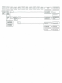
Section 1: Description
1-1
1-2
1 -3
1-4
1-5
1-6
1-7
1-8
1-9
1-10
1-11
1-12
1-13
1-14
1-15
1-16
1-17
1-18
1-19
1-20
Page 1~10
Specifications (M-2400)
Special Features (M-2400)
Safety Features (M-2400)
Specifications (M-2200)
Special Features (M-2200)
Safety Features (M-2200)
Description
Spill Tray
Heater Cabinet
Combustion System
Combustion Chamber
Burner Pot
Combustion Ring Assembly
Flame Sensor
Igniter
Combustion Air System
Flue Pipe
Combustion Blower Motor (M-2400)
Heat Exchanger
Air Circulation Fan
Section 2: Installation
2-1
2-2
2-3
2-4
2-5
2-6
Introduction
Physical Placement of Heater
Drilling Requirements
Power Requirements
Fuel Tank Requirements
Temperature Sensor Wiring
Requirements
2-7 Building Codes
2-8 Un-packing
2-9 Heater Installation
Installation Classification (M-2400)
Section 3: Operation
3-1
3-2
3-3
3-4
3-5
3-6
3-7
3-8
3-9
•
Introduction (M-2400)
Operating Specifications (M-2400)
Introduction (M-2200)
Operating Specifications (M-2200)
Operating Controls and Indicators
Pre-operation Check List
Operation
Manual Heater Operation
Automatic Heater Operation
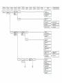
1-21
1-22
1-23
1-24
1-25
1-26
1-27
1-28
1-29
1-30
1-31
1-32
1-33
1-34
1-35
Air Pressure Switch
Fuel Delivery System
External Fuel Tank
Fusible Link Valve
Fuel Constant Level Valve
Solenoid Pump
Electrical System
Microprocessor
Temperature Sensor
Safety Mechanism
Cloth Covered Exhaust Pipe
Air Circulation Fan Guard
Fuse
Overheat Protector Switches (M-2400)
Revolution control of
combustion blower motor
1-36 Combustion Blower Motor (M-2200)
1-37 Overheat Protector Switches (M-2200)
Elements of combustion system (M-2400)
Elements of combustion system (M-2200)
Page 11~27
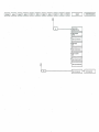
Installation Classification (M-2200)
Applicable Wall Thickness of Flue Pipe
Flue Pipe Clearances
2-10 Installing an Extension Kit
2-11 Typical Monitor Lifter Pump Installations
2-12 Uses for the Elbow Adapter Kit
2-13 Fuel Tank Installation
2-14 Heater Installation
Typical fuel line connections
Back guard (M-2400)
Back guard (M-2200)
Page 28~38
3-10 Programming the weekly timer
for automatic heater operation
3-11 Heat Sensor
3-12 Monitor Shutdown
3-13 Out of Fuel
3-14 Recovery from a Power Failure
3-15 Recovery from Overheat Condition
3-16 Recovery from Blown Fuse
3-17 Operation Control system
M-2400/2200 Operation timing chart
MONITOR HEATING SYSTEMS
Table of Contents
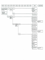
Section 4: Maintenance
4-1
4-2
4-3
4-4
4-5
Page 39—42
Introduction
Periodic Maintenance
Inspect Exhaust /Air Piping
Verify Igniter Operation
Clean Fuel Constant Level
Valve Filter
4-6
4-7
4-8
4-9
Cleaning Fusible Link Valve Intake
Corrective Maintenance
Replacement of Fuses
Fuel Contamination
Section 5: Servicing
5-1
5-2
5-3
5-4
5-5
5-6
5-7
Page 43—47
Introduction
Measurement of Fuel Flow rate
Removal of Water Deposits and Contaminants
from Fuel Constant Level Valve and Fuel Lines
Cleaning the Burn Chamber & Burner Pot (M-2400)
Cleaning the Fuel Inlet (M-2400)
Cleaning the Burn Chamber & Burner Pot (M-2200)
Cleaning the Fuel Inlet (M-2200)
Section 6 : Troubleshooting
Page 49~62
Resistance Values (M-2400)
Component Voltage Readings (M-2400)
Resistance Values (M-2200)
Component Voltage Readings (M-2200)
Test Point Voltage
Troubleshooting Diagrams (Mechanical)
Troubleshooting Diagrams (Electrical)
Indication of Failure mode
Section 7 : Electrical System
Page 63—66
Schematics
Schematics (since February 2004)
Monitor 2400 Printed Circuit Board Wiring Diagram
Monitor 2200 Printed Circuit Board Wiring Diagram
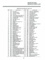
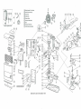
SERVICE PARTS LIST
Monitor 2400 Service parts list
Exploded views (M-2400)
Monitor 2200 Service parts list
Exploded views (M-2200)
•
Page 67-70
MONITOR HEATING SYSTEMS
Section 1: Description
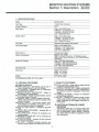
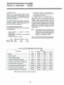
1-1 SPECIFICATIONS
Model
Monitor 2400
Fuel Type
Crystal Clear Kerosene
Heater Efficiency
93%*
Heat Rating
High : 43,000 BTU/hour
H.Medium : 32,000 BTU/hour
L.Medium : 24,600 BTU/hour
Low: 16,200 BTU/hour
Heater Output
High : 37,200 BTU/hour
H.Medium: 26,900 BTU/hour
L.Medium: 20,700 BTU/hour
Low: 13,600 BTU/hour
Fuel Tank
Separate (Not supplied with heater)
Fuel Consumption
High : 0.319 Gallon/hour
H.Medium: 0.24 Gallon/hour
L.Medium: 0.18 Gallon/hour
Low: 0.12 Gallon/hour
Power Source
120 Volts AC ;60Hz
Ignition : 310 Watts
High combustion Operation : 68 Watts(Average)
High to Low 4 steps combustion : 56.5 Watts(Average)
Operations
High : 388 Cubic feet/minute
H.Medium : 388 Cubic feet/minute
L.Medium : 330 Cubic feet/minute
Low : 300 Cubic feet/minute
Power Consumption
Heated Air Delivery
Vent Pipe Hole
-inches Diameter
Dimensions
Height: 26.6 inches
Width: 28.7 inches
Depth : 14.0 inches
Weight
82 Pounds, empty
* Net Efficiency is 88%, A.F.U.E. is 84%
1-2 SPECIAL FEATURES
1-3 SAFETY FEATURES
AUTOMATIC IGNITION
MEMORY BACK UP : Set Memory can be kept in
case of power failure for up to 30 minutes.
DUAL BLOWERS : Separate fans for combustion
and room air circulation.
THERMOSTATICALLY CONTROLLED : Adjusts to
the desired room temperature.
BUILT-IN TIMER : Heater will automatically operate
as programmed by the user.
AUTOMATIC RESET AFTER POWER FAILURE :
Heater will automatically resume operation after
power is restored.
INDICATOR LIGHTS : Easy-to-see signals show
when heater is in operation, when timer is activated, and when the burner is operating.
CHOICE OF FUEL SUPPLY : Connect to separate
tank.
MULTIPLE HEAT EXCHANGER : Extracts 88% of
heat from burner.
CLEAN OPERATION : Products of combustion are
vented outside.
CONSUMES NO RpOM AIR : Air for combustion is
drawn from outside.
EASY INSTALLATION : Includes all parts required
for standard installation.
CHILD LOCK : Prevents accidental operation and
prevents small children from altering the controls.
SAFE RE-LIGHTING : Heater will not restart until its
combustion chamber has cooled.
ELECTRICAL PROTECTION : Heater automatically
shuts off in the unlikely event of a malfunction in
the electrical circuitry or disruption of the power
supply.
NO EXHAUST IN ROOM : Products of combustion
are discharged outdoors.
FLUE PIPE : Outside air is drawn through a pipewithin-a-pipe venting system. This process preheats combustion air and regains heat from exhaust gases.
ZLCAUTIONiALTERNATE POWER
SOURCES
The Monitor 2400 may not operate when powered by sources such as an auxiliary generator,
UPS (Uninterrupted Power Source), inverters,
etc. Check with your dealer for guidance on specific applications.
MONITOR HEATING SYSTEMS
Section 1: Description
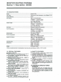
1-4 SPECIFICATIONS
Model
Fuel Type
Heater Efficiency
Heat Rating
Heater Output
Fuel Tank
Fuel Consumption
Power Source
Power Consumption
Heated Air Delivery
Vent Pipe Hole
Dimensions
Weight
Monitor 2200
Red dyed or Clear Kerosene or Low Sulphur *1 Oil
93%*
High : 22,000 BTU/hour
H.Medium : 17,400 BTU/hour
L.Medium : 12,400 BTU/hour
Low: 9,600 BTU/hour
High: 18,260 BTU/hour
H.Medium : 14,440 BTU/hour
L.Medium : 10,290 BTU/hour
Low: 7,970 BTU/hour
Separate (Capsule tank optional)
High: 0.164 Gallon/hour
H.Medium : 0.13 Gallon/hour
L.Medium : 0.19 Gallon/hour
Low: 0.07 Gallon/hour
120 Volts AC ; 60Hz
Ignition : 250 Watts
Operations : 41 Watts (Average)
High : 176 Cubic feet/minute
H.Medium : 176 Cubic feet/minute
L.Medium : 126 Cubic feet/minute
Low : 113 Cubic feet/minute
inches Diameter
Height: 26.0 inches
Width : 20.9 inches
Depth : 13.0 inches
55 Pounds, empty
* When considering heat of condensation is lost, then the net efficiency is 88%, A.F.U.E. is 84%
1-5 SPECIAL FEATURES
1-6 SAFETY FEATURES
AUTOMATIC IGNITION
MEMORY BACK UP : Set Memory can be kept in
case of power failure for up to 30 minutes.
DUAL BLOWERS : Separate fans for combustion
and room air circulation.
THERMOSTATICALLY CONTROLLED : Adjusts to
the desired room temperature.
BUILT-IN TIMER : Heater will automatically operate
as programmed by the user.
AUTOMATIC RESET AFTER POWER FAILURE :
Heater will automatically resume operation after
power is restored.
INDICATOR LIGHTS : Easy-to-see signals show
when heater is in operation, when timer is activated, and when the burner is operating.
CHOICE OF FUEL SUPPLY : Connect to separate
tank or capsule tank optional.
MULTIPLE HEAT EXCHANGER : Extracts 88% of
heat from burner.
CLEAN OPERATION : Products of combustion are
vented outside.
CONSUMES NO RpOM AIR : Air for combustion is
drawn from outside.
EASY INSTALLATION : Includes all parts required
for standard installation.
CHILD LOCK : Prevents accidental operation and
prevents small children from altering the controls.
SAFE RE-LIGHTING : Heater will not restart until its
combustion chamber has cooled.
ELECTRICAL PROTECTION : Heater automatically
shuts off in the unlikely event of a malfunction in
the electrical circuitry or disruption of the power
supply.
NO EXHAUST IN ROOM : Products of combustion
are discharged outdoors.
FLUE PIPE : Outside air is drawn through a pipewithin-a-pipe venting system. This process preheats combustion air and regains heat from exhaust gases.
&CAUTION:ALTERNATE POWER
SOURCES
The Monitor 2200 may not operate when powered by sources such as an auxiliary generator,
UPS (Uninterrupted Power Source), inverters,
etc. Check with your dealer for guidance on specific applications.
MONITOR HEATING SYSTEMS
Section 1: Description
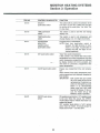
1-7 DESCRIPTION
The Monitor heaters are composed of the following:
a spill tray, a cabinet, a combustion system, an air
circulation system, a fuel delivery system, electrical
and electronics systems and a variety of safety
mechanisms.
1-8 SPILL TRAY
The Spill Tray:
— Protects the floor from damage resulting from
fuel spillage.
— Provides a secure, tip-resistant heater base.
Metal retainers (2) secure the heater to the Spill
Tray.
The legs are positioned with in the circular indentations.
1-9 HEATER CABINET
A steel cabinet holds and protects all internal components.
A number of primary parts are assembled to form
this housing.
1-10 CMBUSTION SYSTEM
The Combustion System is responsible for the production of heat which is circulated into the room .
In the Combustion Systems a mixture of fuel and air
is burned to produce heat. Air is drawn from outside
the dwelling into the Combustion Chamber. At the
same time, fuel is metered from a storage cavity into
this same Combustion Chamber. Within the chamber, the air/fuel mixture is ignited to produce heat.
The Monitor combustion systems are safeguarded
by a pair of overheat protector switches; They will
shut down the heater (to protect it from damage) in
the event of excessive heat build-up. The overheat
protector switches reset automatically after cooling
down.
1-11 COMBUSTION CHAMBER
This tall cylinder is positioned on the Heater Base. It
is secured to the base by phillips head screws.
Connected to the Combustion Chamber are the igniter, (located within the chamber) a fuel line, the
Heat Exchanger, and a Flame Sensor.
Within the Combustion Chamber are the Burner Pot,
the Combustion Ring Assembly. Access to those internally-located parts is facilitated by a removable
Service panel.
A Window on the panel lets the technician visually
examine the combustion process(i.e. glowing igniter
or proper flame color).
An airway, in the Cabinet Base, extends from the intake fan of the Combustion Blower to the hollow
base of the Combustion Chamber. This airway channels air to the Combustion Chamber.
The Flame Sensor is mounted with two (2) phillips
head screws onto the wall of the Combustion Chamber.
1-12 BURNER POT
Designed specifically to support combustion, the
Burner Pot (refer to Figure 1-2/1-3) contains a series
of air holes, an igniter tube (to accommodate the Igniter), and a fuel inlet fitting (interconnects the fuel
line). It is secured to a mounting plate near the bottom of the Combustion Chamber.
The Combustion Ring Assembly is seated on three
(3) screws or pins in the Burner Pot.
1-13 COMBUSTION RING ASSEMBLY
This assembly is a special structure, designed to
promote efficient combustion.
1-14 FLAME SENSOR
Mounted on the outside wall of Combustion Chamber, the Flame Sensor always supervises the flame.
1-15 IGNITER
Located within the igniter tube of the Burner Pot, the
Igniter is designed to pre-heat the Burner Pot and to
vaporize and ignite the air/fuel mixture to start the
combustion process.
The Igniter is secured by a bracket and screw to the
igniter tube. The cover plate is secured to the combustion chamber by three (3) phillips head screws.
1-16 COMBUSTION AIR SYSTEM
The Combustion Air System channels air to and from
the heater.
Outside air is drawn into the heater by the Combustion Blower through an airway to the Combustion
Chamber.
A Combustion Blower draws the intake air in
through a Flue Pipe. This air enters the Combustion
Chamber at the Burner Pot and mixes with the fuel
to support combustion, Remaining air is heated and
is drawn into the Heat Exchanger.
As the heated air passes through the Heat Exchanger, an Air Circulation Fan blows room air past the
Heat Exchanger and out again into the room, heating
passing air by convection. Exhaust vapors exiting
from the Heat Exchanger are vented through the
Flue Pipe.
A deterioration of air pressure at the Air Pressure
Switch is an abnormal condition; the heater is shut
down by the malfunction.
MONITOR HEATING SYSTEMS
Section 1: Description
1-17 FLUE PIPE
The Flue Pipes is adaptable in three (3) sizes. This
provides the flexibility to meet the installation requirements for walls of various thicknesses.
The Flue Pipe is two Sections, Flue pipe A and Flue
pipeB.
air within the exchanger heats the outside metal
walls. The hot metal walls, in turn, heat air that is
pushed past the exchanger and is circulated into the
room. An air baffle, directly in front of the exchanger,
deflects the heated air upwards, and out, through the
louver assembly.
The Flue Pipe A contains a "T"-shaped fitting consisting of four ports. This side is mounted on the interior wall of the dwelling. The Flue Pipe B is vented
outside the dwelling. The Flue Pipe Assembly consists of two concentric tubes. Outside air is drawn
through the cylindrical space between the tubes.
Combustion by-products are vented through the inner tube.
A pair of Over-Heat Protector Switches protect the
heater from damage due to excessive heat built-up.
As the cool air enters, it is heated by the hot air that
is exiting the system.
A large-bore, flexible hose connects the air inlet port
on the Flue Pipe A with the Combustion Blower; a
cloth-covered metal pipe connects the Combustion
Blower with the exhaust outlet on the Flue Pipe A.
IMPORTANT: If extension kits are utilized, use the
correct damper in accordance with the instructions in
table 2-1 of page 14
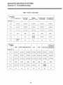
1-18 COMBUSTION BLOWER MOTOR
The combustion blower has a four stage intake fan
Burner modes control fan speeds.
The combustion air controls are as follows:
Table 1-1 COMBUSTION AIR CONTROL (M-2400)
Burn Mode
Fan Speed (r.p.m.)
High
2,800
Medium-High
2,300
Medium-Low
1,900
Low
1,500
Please refer to paragraph 1 -35 in page? for the details of the combustion blower motor control.
1-19 HEAT EXCHANGER
An inlet at the top of the Heat Exchanger permits the
heated air to travel from the Combustion Chamber
into the exchanger.
An outlet, at the bottom of the exchanger, permits
combustion by-products to be vented to the Flue
Pipe.
While moving through the Heat Exchanger, the hot
1-20 AIR CIRCULATION FAN
Circulation fans are driven by three-speed motors
and are designed to circulate the heated room air.
If the heater is running in low burn modes, the fan
also runs at low-speed; in medium-low burn mode,
the fan runs at medium-speed; in medium-high or
high burn modes, the fan advances to high speed.
Operation of the fan is controlled by the microprocessor and fan thermostat switch.
Physically assembled with a protective wire cage for
the heater, the entire fan assembly is secured to a
bracket on the rear of the Heater Cabinet.
A metal conduit, at the rear of the heater, protects
the fan wiring from damage.
1-21 AIR PRESSURE SWITCH
This switch consists of a rubber diaphragm which
senses changes in air pressure(it is connected to the
Combustion Blower) and is a normally open, micro
switch.
Should an abnormal pressure differential exist, the
switch opens to disable the circuitry that controls the
supply of fuel. Since the flow of fuel to the Burner
Pot is cut off, the flame extinguishes (after all fuel
currently in the line has been consumed), and the
code fE14jis indicated in the digital display.
This safety mechanism can be triggered by several
conditions:
— Leak or loose connection in air line
— Leak, loose, or broken tubing which connects the
Air Pressure Switch with the Combustion Blower
— Clogged or blocked Air Line
— Blocked or clogged Flue Pipe
— Intake port Combustion Blower is blocked.
— Combustion Blower is inoperable
— Clogged or block air/intake hose.
MONITOR HEATING SYSTEMS
Section 1: Description
1-22 FUEL DEUVERY SYSTEM
Fuel Delivery is a very important aspect of the
Monitor's operation.
The fuel flow must be maintained at a level corresponding to the burn mode, so that combustion can
be conducted efficiently.
Fuel moves by gravity-flow from the external fuel
storage tank or the capsule fuel tank to the Fuel
Constant Level Valve.
The Solenoid Pump meters the flow of fuel from the
Fuel Constant Level Valve to the Burner Pot.
The metered flow of fuel is carried to the Burner Pot
by a copper fuel line.
1-23 EXTERNAL FUEL TANK
Fuel for the Monitors can be stored in, and fed from
an external storage tank. The tank, which generally
is dealer installed, should contain a shutoff valve, a
fuel filter and a vent. Installation of the tank should
conform to local regulations and to the specifications and guidelines documented in this Service
Manual.
1-24 FUSIBLE LINK VALVE
Basically, the Fusible Link Valve is a safety mechanism that cuts-off fuel to the heater in the event of
an overheat condition at the valve.
In M-2400/M-2200, Fusible Link Valve is not installed, If necessary, it can be installed outside of the
appliance.
The Fusible Link Valve is a springloaded device that
cuts off the supply of fuel to the heater when the
temperature level (at the valve)
exceeds a predefined maximum limit.
An inlet on the bottom of the valve allows fuel to
pass into the heater. The handle-which can also
manually be opened or closed-sits on a springloaded stem which contains a low-melting point
alloy.
1-25 FUEL CONSTANT LEVEL VALVE
This valve has an automatic shutoff safety mechanism and a Fuel Set Lever. The safety mechanism
prevents fuel from flooding or overflowing from the
fuel reservoir. The Fuel Set Lever resets the float so
the Fuel Constant Level Valve can resume operation.
The fuel reservoir is a tank which contains a float
assembly, a safety mechanism, and a priming lever.
Fuel enters the Fuel Constant Level Valve through
an inlet at the bottom of the reservoir. As the level
of fuel rises, it passes through a filter (which
removes most particles and foreign matter from the
fuel), flows up through an open inlet valve and
enters the tank.
IMPORTANT:
The Fuel Constant Level Valve filter
should be cleaned or replaced periodically. Time intervals will depend
on purity and quality of fuel.
Within the Valve, a float mechanism controls the
level of fuel that will be permitted to the reservoir. As
the fuel level drops, the float drops down to increase
the inlet valve opening to admit more fuel into the
valve. When the fuel level reaches its maximum
volume, the float rises to shut the inlet valve.
In the event that fuel within the reservoir rises to an
abnormally high level, a float within the reservoir
rises to trip a safety magnet. This safety magnet
locks out the float to prevent fuel from entering in the
reservoir.
Should a foreign substance cause the inlet valve to
stick (or prevent it from opening), the Fuel Set Lever
is utilized to free the valve and to admit fuel to the
reservoir.
A CAUTION: Care must be taken to prevent
dust, dirt, or other debris from
clogging or blocking the inlet
valve. If debris collects on the
seat of the inlet valve it may
cause tripping of the safety lever
and will require cleaning.
MONITOR HEATING SYSTEMS
Section 1: Description
During installation make sure that all Exhaust Lines
are tight. Do not operate the heater without the
insulating covers.
1-26 SOLENOID PUMP
The Solenoid Pump, mounted on the Fuel Constant
Level Valve, and controlled by a microprocessor,
delivers four fuel flow modes (High, Medium-High,
Medium-Low, Low) to the Burner Pot.
1-32 AIR CIRCULATION FAN GUARD
This guard is an integral part of the fan assembly.
1-27 ELECTRICAL SYSTEM
Electrical power is supplied to the Monitor to run the
Microprocessor and the other electrically-energized
component.
The guard protects the user against physical injury
which could occur from accidental contact with
revolving metal fan blade.
Electrical operation of the Monitor can be thought of
as having the following eight(8) distinct phases.plug
in; turn-on; pre-purge/pre-heat; ignition; precombustion; heating; Shutdown and post-purge.
1-33 FUSE
2-amp. and 10-amp., 125VAC, fuses protect the
heater from damage resulting from power overloads.
In the event of a power surge or internal wiring
hazards, the fuse opens and power to the heater is
cut off.
All electronic diagrams, Such as wiring diagram,
circuit board layout, and electrical schematic can be
found in Section 7 of this Service Manual.
The electrical outlet into which the heater is connected should be protected by at least a 15-amp.
fuse or circuit breaker.
1-28 MICROPROCESSOR
Principally consisting of a 64-pin Integrated Circuit,
the Microprocessor provides safety timings, controls
relays and provides clock and thermostat functions
for the Monitor heater. A component layout of the
Printed Circuit Board is found in Section 7 of this
Service Manual.
1-34 OVERHEAT PROTECTOR SWITCHES (M-2400)
Connected in series, two (2) normally-closed Overheat Protector Switches safeguard the heaters
against damage due to overheating.
The switches are rated 115'C (239'F). Should a
Monitor overheat (internal temperatures rise beyond
115'C (239'F)). either or both switches will open to
shut down the heater. After extinguishing the flame,
the code FE14J is indicated in the digital display.
The Overheat Protector Switches will automatically
reset after cooling down.
1-29 TEMPERATURE SENSOR
The sensor which is capable of sensing room temperature within a range of 42"F to 96°F, can be left
mounted on the back of the heater cabinet or be
wall mounted.
Approximately 4/^'(about 140 cm) of No. 22 AWG
Wire is supplied with the sensor to facilitate wall
mounting the sensor in a favorable location.
Once the heater has cooled to 90'C (194*F), the
system can be restarted. To restart the Monitor,
proceed as follows:
1-30 SAFETY MECHANISMS
Several safety mechanisms have been built into the
Monitor Heating System. These devices protect the
user against personal injury, protect the heater
against damage, and shutdown the heater if a
malfunction occurs.
A.
B.
C.
D.
E.
1-31 CLOTH COVERED EXHAUST PIPE
Insulating cloth covers are to be placed over all
metal surfaces of the Exhaust Line during installation.
Since combustion by-products are vented at elevated temperatures, the Exhaust Pipe will become
hot during operation. The insulating cloth covers
protect the user from burn hazards associated with
accidental contact with these heated metal surfaces.
6
Press ON/OFF Switch to OFF.
Allow heater to cool.
Troubleshoot the cause of the overheat.
Press ON/OFF switch to ON
Proceed with normal operation.
MONITOR HEATING SYSTEMS
Section 1: Description
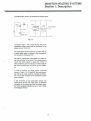
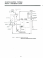
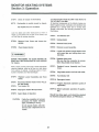
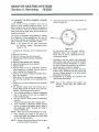
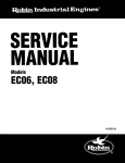
1-35 Revolution control of combustion blower motor
-o 5V
IC4
TRIAC L
01 JT
fSfj
1
Hole 1C
microprocessor
Fig. 1-1
As shown in Fig.1-1, the current-carrying ratio for the
combustion blower motor shall be performed by the
phase control, TRIAC, Q1.
The combustion blower motor has a built-in hole 1C
of which input signal is entered to the microprocessor through the comparator IC8.
The hole 1C outputs the pulse signal by 6 pulse every one revolution of the motor. The microprocessor
counts this pulse signal to obtain the number of
pulse, frequency per one second, and then compute
the motor revolution -per one minute by this frequency.
In order to achieve the target control revolutions
shown in Table 1-1/1-2, Page 4/8, the current-carrying ratio to the motor shall be controlled by TRIAC,
Q1 to make the revolution of the combustion blower
motor constant.
If the revolution of the combustion blower has
slowed down to less than 1200 (rpm), an abnormal
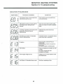
revolution will be sensed and then the heater operation will be stopped indicating the error code of (EOS)
in the display window.
MONITOR HEATING SYSTEMS
Section 1: Description
1-36 COMBUSTION BLOWER MOTOR
The combustion blower has a four stage intake fan
Burner modes control fan speeds.
The combustion air controls are as follows:
Table 1-2 COMBUSTION AIR CONTROL
Burn Mode
Fan Speed (r.p.m.)
High
2,975
Medium-High
2,550
Medium-Low
2,025
Low
1,800
1-37 OVERHEAT PROTECTOR SWITCHES
Connected in series, two (2) normally-closed Overheat Protector Switches safeguard the heaters
against damage due to overheating.
The switches are rated 110'C (230T) and 105'C
(221 'F). Should a Monitor overheat (internal temperatures rise beyond 105'C (221'F). either or both
switches will open to shut down the heater. After extinguishing the flame, the code [EOS] is indicated in
the digital display. The Overheat Protector Switches
will automatically reset after cooling down.
Once the heater has cooled to 90'C (194T), the
system can be restarted. To restart the Monitor,
proceed as follows:
A.
B.
C.
D.
E.
Press ON/OFF Switch to OFF.
Allow heater to cool.
Troubleshoot the cause of the overheat.
Press ON/OFF switch to ON
Proceed with normal operation.
8
MONITOR HEATING SYSTEMS
Section 1: Description
UJ
en
z
o
CO
m
S.
o
o
LL
O
CO
UJ
UJ
2
9
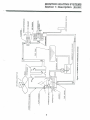
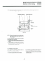
MONITOR HEATING SYSTEMS
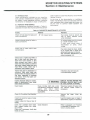
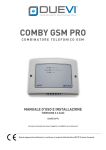
Section 1: Description | M-2200
AIR CIRCULATION FAN
FLUE PIPE
^•^U^-S
FLAME SENSOR
CAPSULE
FUEL TANK
EXTERNAL
FUEL TANK
COMBUSTION RING
BURNER POT
AIR PRESSURE SWITCH
\CONSTANT LEVEL VALVE
Figure 1-3 ELEMENTS OF COMBUSTION SYSTEM
NOTE: Capsule tank cannot be used in Connecticut.
10
MONITOR HEATING SYSTEMS
Section 2: Installation
RECOMMENDED TOOL KIT FOR MONITOR
HEATER SERVICE TECHNICIANS
1) #2 Phillips Head Screwdriver
2) Steel Tape Measure
3) Felt Tip Pen or Pencil
4) Caulking Material (exterior grade)
5) Electrical Drill
(reverse capability recommended)
6) Hole Saw, Saber (Jig) Saw, or other appropriate
tool for cutting a 2.5" diameter hole for flue pipe
7) Rubber Clipping Tool
8) Long Drill Bit—'//'
9) #2 Standard Screwdriver
10) Adjustable Wrenches (various sizes)
11) Copper Tubing Cutter
12) Copper Tubing Flaring Tool
13) V.O.M.(Volt. OHM. Meter with shielded probes)
14) Level
15) Plumber's Pipe Thread Tape
16) Small assortment of Self-Tappeng Screws
17) Assorted Pliers (Slip Joint, Needlenose, Cutting,
Lock Joint)
18) Phenolic Probe or Insulated Screwdriver
19) Supply of 125V, 2 and 10 Amp fuses
20) Floor mat to cover carpeting
21) Quart size pan for draining fuel
2-1 INTRODUCTION
Installing the Monitor System at the user's location
can be performed quickly and economically.
The Monitor 2400/2200 model is strictly a remotely
fueled system and is externally vented. As such it
needs the installation of an externally vented intake/
exhaust system and if remotely fueled, will need the
installation of a remote fuel storage tank.
By completing each step of the easy-to-follow
installation instructions (each step should be completed in the exact order specified), the Technician
is directed through the installation process.
This section contains all relevant installation information including:
— Installation specifications
— List of installation tools
— Alternative types of venting systems (and installation procedures for each)
— Basic requirements for fuel tank installation
— Instructions to install the Monitor System
IMPORTANT: Before beginning installation of the
Monitor vented heating system (including any electrical wiring and
fuel supply equipment), check local
building,electrical, mechanical and
fire codes. The requirements of
these codes must be followed to
insure lawful installation and use.
2-4 POWER REQUIREMENTS
WARNING:
The heater can be located almost anywhere within
the dwelling provided that electrical, fuel, and exhaust specifications are met.
THE MONITOR POWER CORD MUST BE PLUGGED
INTO A DIRECTLY ACCESSIBLE WALL OUTLET.
DO NOT USE AN EXTENSION CORD TO MAKE
THIS ELECTRICAL CONNECTION.
2-2 PHYSICAL PLACEMENT OF HEATER
In addition to the space taken up by the heater,
interior space must also be reserved for free air
circulation. Remove all combustibles from the heating area.
Line current to the system should be 120 VAC at 60
Hz. The electrical system should be protected
against current overload by means of at least a
15-ampere fuse or circuit breaker.
Unless building or fire codes dictate otherwise, the
Monitor system can be placed on any floor surface
(including carpeting or other combustible material)
and provide safe operation.
NOTE: The wall outlet should supply electricity for
the Monitor system only. Do not connect
any other electrical appliance to it.
2-3 DRILLING REQUIREMENTS
Through-the-wall Flue Pipe installation requires that
a 2 Vz" (65mm) hole be drilled through the dwelling
wall (interior to exterior). The hole must be pitched
downward toward the outside at an approximate
angle of 2"(about l/2" per foot). The appropriate wall
area (in which hole will be drilled) must contain no
internal obstacles such as piping, wiring, air ducts,
or studs.
^CAUTION: In some installations, it may be
best to hard-wire the heater to the
house circuits. A competent,
licensed electrician should do
this.
11
MONITOR HEATING SYSTEMS
Section 2: Installation
NOTE:
2-5 FUEL TANK REQUIREMENTS
WARNING:
INSTALLATION OF ANY REMOTELY LOCATED
FUEL TANKS MUST COMPLY WITH ALL LOCAL
STANDARDS AND/OR BUILDING CODES.
D.
E.
F.
Heater fuel (crystal clear kerosene only) can be
stored in remotely located storage tanks ranging
from 55 gallon drums to 275 gallon tanks. When
using large tanks a pressure regulator with a max. of
2.5 PSI should be installed near heater inlet,
(if top of tank is going to be 8' higher than base of
unit.)
G.
H.
I.
/JK.CAUTION: In some installations, it may be better to install permanent fuel tank
plumbing. A licensed plumber or
oil dealer should do this.
The Dealer should complete the Registration Card at time of customer purchase and
return it to Monitor Products, Inc. as soon
as possible.
Remove the spill tray from shipping carton, and
remove the plastic bag.
Remove the plastic bag covering the heater.
Remove the plastic bag containing the heater
parts.and set it aside.
Remove the Flue Pipe from the rear of the
heater. When ready to install, separate Flue
Pipe from cardboard packing materials.
Firmly grasp cabinet handles (one of each side
of heater cabinet) and lift heater off the cardboard shipping base.
Check for parts as listed in Monitor Owners
Guide.
IMPORTANT: Only the standard-size Flue Pipe
is shipped with the heater. The
Monitor dealer will also stock a
longer Flue pipe B and a Relay
pipe, Window Kits, Extension
Kits, and other accessories that
may be required for non-standard
installations.
2-6 TEMPERATURE SENSOR WIRING REQUIREMENTS
A wall-mounted temperature Sensor gauges room
temperature and automatically regulates the heating
cycles of the Monitor System.
The standard sensor wire is 4/£' long and can be
left mounted on the back of the cabinet as shipped.
If this is not practical the sensor can be mounted on
a wall.
il\CAUTION: If sensor is to be mounted re, motely be careful not to place it in
direct sunlight, on uninsulated
exterior walls in drafty areas etc.,
as this will create an inaccurate
temperature reading.
2-7 BUILDING CODES
Fire regulations, electrical and other local building
codes may govern the installation and use of a
vented heater and related fueling systems. Prior to
installation, check and comply with all codes.
2-8 UNPACKING
Save all shipping materials until the Monitor has
been completely installed and is working properly.
A. Cut the three plastic ribbons that hold the shipping carton together.
B. Remove the top.
C. Remove from the shipping carton the Cardboard
(drilling) Template and the Owner's 'Guide.
12
MONITOR HEATING SYSTEMS
Section 2: Installation
NOTE: After using the installation template as a
guide for drilling the flue pipe hole, the Monitor Flue Pipe can be normally installed according to the illustration procedure in the
Monitor Manual.
2-9 HEATER INSTALLATION
In choosing a location for your heater, the following
guidelines must be considered:
• The heater MAY be installed on combustible
floors.
• The area around the heater should be free of obstacles that might interfere with the free flow of air.
Allow the clearances shown in Figure 2-1.
• The heater must not be installed in a combustible
fireplace.
• An AC wall outlet must be within reach of the heater's power cord. Extension cords must not be
used.
• The area outside where the flue pipe will emerge
should be free of foliage, fuel storage tanks and
flammable objects. Air should circulate freely in the
area. Allow the clearances shown on following
page.
• The wall where flue pipe hole will be cut should be
free of plumbing pipes, electrical wires, studs, air
ducts and other obstacles.
Just in case the template was misplaced, the approximate flue pipe hole location measurements are
as follows:
The center of The Joint Pipe'
opening, which connects
to the Flue Pipe.
Back of Heater
12" (30cm)
5V2"
(13.5cm)
The center of The Joint Pipe
opening, which connects
to the Flue Pipe.
Back of Heater
39"
(100cm)
Fig. 2-1
M-2400
M-2200
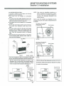
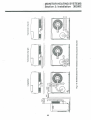
If the unit is installed so that it is enclosed on both sides
and top, the following instructions shall be carried out.
With the side and top clearances as shown in the
illustration (Fig. 2-2) the front of the Monitor shall be
placed so that the front surface protrudes 5 inches
(12.5 cm) beyond the enclosure. (See Rg. 2-3)
With the side and top clearances as shown in Fig. 2-4,
the Monitor shall not be placed so that its front surface
is inside of the enclosure.
5"min
(12.5cm)
(13.5cm)
6"min
(15cm)
6'min
(15cm)
6"min
(15cm)
6"min
(15cm)
Rg. 2-2
.115cm)
Fig. 2-3
M-2400
13
Fig. 2-4
Fig. 2-5
M-2200
MONITOR HEATING SYSTEMS
Section 2: Installation
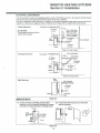
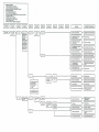
Table 2-1 Installation Classification for using Damper Diameter and Processing
of P.W.B. Jumper Wire CJ
Altitude (feet)
Installation Classification
0~3,000
Air
Damper
Up to 1 bend(90°elbows) with no
extension
3,000—5,000
Blower
Damper
STANDARD Used
Used
Up to 1 bend(90'elbows) with
extension kit length : 0-73"
2 bends with extension kit length :
exceed 20" or 3 bends
EXTENSION Used
Used
P.W.B. Jumper Wire CJ
Air
Damper
Blower
Damper
Air
Damper
Blower
Damper
STANDARD
Used
Used
Not Used
Used
Not Used
Not Used THIS UNIT CAN NOT BE
EXTENSION Used
Used
Not Used
Not Used
USED FOR THIS
APPLICATION.
Cut
No Cut
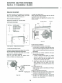
The blower damper is fixed with suction case B of
the combustion blower ass'y, as shown in Fig. 2-6.
To remove the blower damper from suction case B,
remove the air hose supply ass'y, first and then
loosen the screw holding the blower damper.
After the blower damper has been removed, insert
air supply hose ass'y into the suction case B and
tighten by the hose band.
5,000-7,000
[Position of P.W.B. jumper wire CJ and reset pushbutton switch]
Reset push-button
- switch
^ Jumper wire CJ
D
Suction case B
Combustion blower assy
P.W.B.
Blower damper
IMPORTANT:
After cutting the jumper wire CJ, please be sure to
press the reset push-button switch on the P.W.B.
two to three times, with the power plug inserted in
the socket.
If the reset button has been pressed, settings such
as the current time, current day of the week,
economy plus and child lock functions will be
cancelled, and these programs must be set again.
Hose band
Screw
Air supply hose assy
Fig. 2-6
14
MONITOR HEATING SYSTEMS
Section 2: Installation
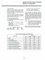
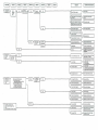
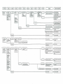
Table 2-2 Installation Classification for using Damper Diameter and Processing
of P.W.B. Jumper Wire CJ
0~700m
0—2330 ft
Altitude
700— 1400m
2330— 4660ft
1400— 2100m
4660— 7000ft
Air Damper
Air Damper
Air Damper
Up to 1 bend (90'elbows) with
Extension kit length of 0-73 in.
STANDARD
USED
EXTENSION
USED
NOT USED
Up to 2 bends (90°elbows) with
Extension kit length of 0-38 in.
STANDARD
EXTENSION
NOT USED
Up to 3 bends (90'elbows) with
No Extension.
STANDARD
EXTENSION
NOT USED
EXTENSION
USED
NOT USED
DO NOT
INSTALL
NOT CUT
CUT
CUT
Installation Classification
NOTE: IT IS IMPORTANT TO
USE THE CORRECT DAMPER
SHOWN IN THIS TABLE.
IMPORTANT:
Installations that exceed any of
the limits above.
P.W.B. Jumper Wire CJ
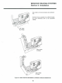
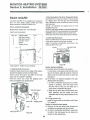
The air damper is fixed with air intake flange of the
Flue pipe, as shown in Fig.2-7.
Remove the air supply elbow to remove the air
damper from the air intake flange.
After the air damper has been removed, insert air
supply elbow into the air intake flange and tighten by
the hose band.
[Position of P.W.B. jumper wire CJ and reset pushbutton switch]
Reset push-button
. switch
oD'
^ Jumper wire CJ
P.W.B.
IMPORTANT:
After cutting the jumper wire CJ, please be sure to
press the reset push-button switch on the P.W.B.
two to three times, with the power plug inserted in
the socket.
If the reset button has been pressed, settings such
as the current time, current day of the week,
economy plus and child lock functions will be
canceled, and these programs must be set again.
Air intake flange
Air supply
elbow
Flue pipe
A|r damper
Fig. 2-7
15
MONITOR HEATING SYSTEMS
Section 2: Installation
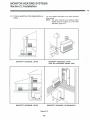
In case the flue pipe will be installed in the wall thickness more that 8.5in., the optional part, Flue Pipe Kit
should be used.
For the types of flue pipe kits and their applicable
wall thickness, please refer to Table 2-3.
Applicable Wall Thickness of Flue Pipe.
The flue pipe attached to the heater can be installed
in the wall thickness from 0.6in.(1.5cm)up to
8.5in.(22cm).
Standard Flue
Pipe
Thickness of walls
1.5cm ~ 12.5cm
0.6in~5in
Flue Pipe A
,Sleeve Nut
nrK
/Flue Pipe B
Since the installing
dimension can not
be decrease to less
than Sin.
(12.5cm), fix the flue
pipe by using the
Sleeve Nut attached
to the heater.
s— Wall Thickness 1.5 cm - 12.5 cm
Thickness of walls
12.5cm~22.0cm
Sin ~8.5in
Flue Pipe A
Flue Pipe B
y/\<Z.
Medium Adjustable Thickness of walls
Flue Pipe Kit
22.0cm~31.5cm
8.5in~12.5in
Flue Pipe A
Medium Adjustable
Flue Pipe B
(P/N.8051)
A
Long Adjustable
Flue Pipe Kit
Thickness of walls
31.5cm ~ 50.5cm
12.5in~20in
Wall Thickness 12.5 cm - 22.0 cm
s£r- Wall Thickness 22.0 cm - 31.5cm
Flue Pipe A
Relay Pipe (P/No.8052)
Flue Pipe B
Wall Thickness
31.5cm~ 50.5cm
Table. 2-3
A CAUTION
Please be sure to observe the instruction for the
types of Flue Pipe Kit and their installing wall thickness.
Do not install any fuel pipe kit beyond its maximum
applicable wall thickness, since the connection of
Flue Pipe A with Flue Pipe B, or Flue Pipe A, B, and
Relay Pipe will be incomplete, it will create a hazard
because of exhaust gas leakage.
16
MONITOR HEATING SYSTEMS
Section 2: Installation
FLUE PIPE CLEARANCES
The vent terminal of a direct vent appliance with an input of 50,000 Btu per hour or less shall be located at least
9 inches from any opening through which flue gases could enter a building.
Flue pipe installations should provide for venting to an unconfined space through which there is a free flow of
outdoor air. Clearances to adjacent walls or obstacles must comply with the requirements shown below.
Frontal Clearance
Combustible iiiiniiiiminimiiinintiiniiniiii
12" (30cm)
A CAUTION:
Do not attach anything onto the
outlet of the flue pipe.
or more
J13.5cm)
Wall Clamp
-f-Wall
Any construction
above Flue Pipe
must not come
within 24'(60cm)
of front obstacle
-24'(60cm)
or more
i-—Flue Pipe
3"
(7.5
cm)
or
more
I Front Obstacle
~T~
8T(20cm)
or more
Ground or slab surface
Overhead Clearance
Non-combustible
Combustible
Ground or slab surface
Wall
Clamp
Side Clearance
Side obstacle
T
18" (45cm)
or more
Heater-
IMPORTANT:
Flue Pipe
-Wall
Figure 2-8
(1) In areas of heavy snow falls, ground surface
clearance must be increased according to average
snow falls, to prevent flue pipe from being buried.
(2) In open area with strong wind, a wind break
may be necessary,
Long
Extension
kit
u»-
=»
Figure 2-9
17
24"min .
(60cm)
MONITOR HEATING SYSTEMS
Section 2: Installation
IMPORTANT:
2-10 INSTALLING AN EXTENSION KIT
Installing an Extension Kit requires the construction
of an air line and the exhaust line. The air line is
connected between the Air Supply Elbow at the rear
of the heater and the air inlet port on the Flue Pipe.
Similarly, the exhaust line is connected between the
joint pipe at the rear of the heater, and the exhaust
port on the Flue Pipe.
The PVC air line is longer than the
exhaust line and may need to be cut
to size. Be sure, however, to thoroughly deburr all rough edges.
10
Part No.:
8002 Long Extension Kit
38 to 73 inches
8003 Medium Extension Kit
20 ^A, to 38 inches
8004 Short Extension Kit
11 >£ to 20 >J inches
8212 Extra Short Extension Kit 7^ to 1l)i inches
Figure 2-10 COMPONENTS OF EXTENSION KIT
ITEM?
DESCRIPTION
ITEM;
DESCRIPTION
1
PIPE, Air supply
6
PIPE CLAMP, Bottom
2
JOINT, Air line
7
SCREW. Legs, mounting
3
ELBOW 90
8
SCREW, Pipe Clamp
4
LEG, Wall-standoff
9
BOND. Adhesive
5
PIPE CLAMP, Top
10
Air line
18
EXHAUST INSULATING SOCK
MONITOR HEATING SYSTEMS
Section 2: Installation
Max lengths and bends allowable using extension
kits.
Extension kits are available in four different lengths.
For exact dimensions refer to the accessories
catalog.
1-90° Bend
FtMax
3-90° Bends
10 FtMax
Figure 2-11 MAX LENGTHS AND BENDS ALLOWABLE USING EXTENSION KITS
19
MONITOR HEATING SYSTEMS
Section 2: Installation
2-11 TYPICAL MONITOR LIFTER PUMP INSTALLATIONS
For more detailed information look under Kerosene
Lifter manual.
NOTE: The same minimum and maximum pump
heights must be maintain as is with other
fuel tanks. Figure 2-15.
MONITOR™ KEROSENE LIFTER
MONITOR™ KEROSENE LIFTER
(CAN BE POSITIONED BEHIND UNIT)
MONITOR™ KEROSENE LIFTER
MONITOR™ KEROSENE LIFTER/GRAVITY
Figure 2-12
20
MONITOR HEATING SYSTEMS
Section 2: Installation
2-12 USES FOR THE ELBOW ADAPTER KIT
F
Convert from Monitor 20/30 to 2200/2400 using
an elbow adapter Kit (part#8213A) and utilizing
existing flue pipe installation.
NOTE:
PARTS UST EXPLODED
Name
No
Ref.
of
,
in
No.
Part
Unit
1 Exhaust Pipe Clamp
2 Exhaust Elbow
1
3 Exhaust Joint
1
4 Joint Supporter
1
5 Heat Insulation Cover
1
6 Self-Tapping Screws
2
7 Hose Clamp (this part comes with your
Monitor"" Heater)
8 Air Damper (this part comes with your
Monitor™ Heater)
9 Flue Pipe (this part comes with your
Monitor™ Heater)
A.
B.
C.
D.
E.
Remove metal cap on side mounted exhaust
port of flue pipe and replace into the port.
G.
Be sure the exhaust elbow is firmly fixed on
the flue pipe with a joint supporter.
Insert air supply elbow opening over flue pipe
air intake flange and secure with hose clamp.
NOTE:
The Standard Air Damper is installed over
the flue pipe "air intake flange." (To locate
flue pipe "air intake flange", see your
Monitor™ Owner's Guide.)
Elbow adapter kits may also be used to raise a flue
pipe high enough to clear certain base board heating systems.
2-13 FUEL TANK INSTALLATION
Pictorial views of alternative types of storage facilities and delivery systems are illustrated (Figure
2-15).
Since fuel storage tank installation techniques vary
from place-to-place (often dependent upon applicable codes), a particular installation procedure
cannot be specified. However, certain criteria govern
the fuel hook-up of the Monitor. Use the following
check list as a guide to the fuel storage facilities:
Remove Monitor 20/30 heater and flue pipe.
Install Monitor 2200/2400 fluo pipe into sleeve.
Slide the exhaust elbow onto the exhaust port
opening on the rear of the heater. (To locate
exhaust port opening, see your Monitor Owner'
s Guide.)
Secure the exhaust elbow by attaching the
exhaust pipe clamp to the heater cabinet with
two self-tapping screws.
Cover the adjustable exhaust pipe with heat
insulation cover.
WARNING:
USE ONLY CRYSTAL CLEAR KEROSENE. NEVER
USE GASOLINE, WHITE GAS, CAMP FUEL OR
OTHER FLAMMABLE LIQUIDS. USE OF SUCH
FUELS CAN RESULT IN AN EXPLOSIVE RRE AND
CAUSE SEVERE INJURY.
Fueling Options Available
Fueling of the Monitor Heating Systems can be
accomplished in one of 2 ways:
1.
Gravity Fed Large Capacity External Tank:
Practical for large heating needs where bulk
delivery of kerosene is available. This system
should be installed by a qualified plumber or
fuel supply technician.
*2. Large Capacity External Tank with Pump: For
large heating needs where a gravity fed
system is not practical. An electric pump, the
Monitor™ Kerosene Lifter, especially designed
for use with Monitor heating systems.
*if a pumping system is used to supply fuel, the
inlet pressure to the heater must not exceed 2.5psi.
Figure 2-13
21
MONITOR HEATING SYSTEMS
Section 2: Installation
To install a large capacity, gravity fed external tank,
follow the instructions below. Use of a qualified
installer is recommended.
55, 100, and 250 gallon tanks must contain:
•
•
•
•
•
•
•
•
•
•
•
•
•
Installation height of the bottom of the fuel tank
should be 16 inches or more above the floor
surface on which the heater stands. This
insures that inlet fuel pressure will be sufficient.
The top of the fuel tank should be no higher
than 8>2 feet above the floor under the heater.
This insures that inlet fuel pressure will not be
excessive.
The horizontal length of piping should not
exceed 100 feet and should be free of sharp
bends or obstructions. If using lifter pump, max.
length of piping is 164 ft.
Piping should include no inverse U-type bends
(to avoid air locks, which could block the fuel
supply).
Only % inch OD copper tubing should be used.
The tubing should be bent carefully to avoid
crimping.
A fuel filter is recommended for use on the fuel
line near tank, and a shut-off valve should be
installed at the tank.
Flare connections should be used at the fusible
link valve connection on the heater and at the
fuel filter to be installed at the tank.
The fuel tank should be located no closer than
3 feet from flue pipe.
The fuel tank should have an opening for filling
on the top and a vent with a weather-proof cap
on the side. On some tanks the vent and fill
spout use the same opening.
Shut-off valve at tank outlet
Disposable fuel filter (protects heater against
condensation and other impurities)
Fueling inlet (protected by weather-proof cap)
Ventilation outlet
Clearance of at least 3 from any source of heat
Allowable Height Dimensions:
•
Bottom of tank-at least 16" above floor holding
heater (maintains sufficient pressure)
• Top of tank-maximum of &/•£' above floor
holding heater (prevents excessive line pressure above 2.5 psi).
•
Position of Lifter-more than 8' above fuel inlet
of heater requires pressure reduction valve.
RECOMMENDATION
Pipe fittings in the fuel supply to the Monitor heating
systems should be sealed with pipe thread tape.
The supply line from the tank to the Monitor1*1
Kerosene Lifter must be absolutely air tight. 275
gallons and bigger tanks should have a 2.5 P.S.I,
max pressure reducer to avoid excessive pressure
at heater inlet.
2-14 HEATER INSTALLATION
The Monitor heaters can be physically situated on
carpeting or other combustible flooring with complete safety. The selected heater site must be
accessible to an electrical outlet, must support free
air ciculation (both internal and external), and must
not contain combustible materials in the heater's
immediate vicinity.
Pressure
Reducer
Interior or
exterior gravityfed 55, 100, or 275gallon tank
Lifter circulates
fuel from remote
storage tank
Figure 2-14 ALTERNATIVE SOURCES OF FUEL STORAGE
22
MONITOR HEATING SYSTEMS
Section 2: Installation
Outdoor Fuel Tank
Shut-off Valve
Flare Connection
1>
%• Flare Connection
Fusible Link
Valve Connection
//
Fuel Filter
//
maximum
(2.6m)
(0 4m)
'
f OD Coppor Tubing
CAUTION: Ensure that there is no fuel leakage
from any of the fuel line fittings and
connections.
NOTE: Fuel tank must be a minimum 3 feet away from
flue pipe.
When choosing a filter or a replacement element do not
use the felt type elements.
NOTE2 : A fusible link valve should be installed in the
fuel line behind the heater.
Check local codes and regulations.
Figure 2-15 TYPICAL FUEL LINE CONNECTIONS
23
MONITOR HEATING SYSTEMS
Section 2: Installation
BACK GUARD
2. Install Top Back Guard
Place Top Back Guard so that the dent is to the left
as viewed from the back of heater.
Attach by placing and tightening the screws in the
holes provided.
The BACK GUARD KIT is available as an accessory
item. For more details, please contact your local
dealer distributor or Monitor Products, Inc.
How to install the back guard
M2400 BACK GUARD KIT : Parts No.8306
Top Back Guard
PARTS LIST EXPLODED
Screws
Dent
REF. No.
1
2
3
4
5
PARTS NAME
Side Back Guard L
Side Back Guard R
Top Back Guard
Screws
Tapping Screw
QTY
1
1
1
2
4
Fig. 2-17
Tools required : Phillips head screwdriver
1. Install the Side Back Guard
Locate the holes along the back edge of the cabinet,
and start the tapping screws into those holes.
These screws will support the sides of the back
guard, but do not tighten completely.
Insert the screw tabs under the tapping screw
heads, and tighten each tapping screw.
Side Back Guard
Screw Tab \ japping Screw
Fig. 2-16
24
Caution during installation
(1) Fuel inlet valve at the back of the heaters :
If a fuel valve is connected at the fuel inlet at the
back of the heater, adjust the position of the fuel
valve so that its control knob does not touch the
back guard.
(2) In the case of a standard installation (Flue pipe
directly behind the heater):
1. In order to install the back guard on a heater
already in operation, move the heater away
from the wall so that you can easily use a
screw driver to install the side pieces.
2. Install the top piece after the side pieces have
been attached, and the heater has been
reinstalled with the wall clamps attached to the
wall.
(3) If using extension kits :
Install the back guards in accordance with Figure
2-18, page 25.
Caution in using the back guards
(1) Remove the top back guard when cleaning the
circulation fan assembly and rear of heater.
(2) To prevent overheating the Monitor, ensure that
the slits in the back guard are not blocked by
curtains or other obstructions.
MONITOR HEATING SYSTEMS
Section 2: Installation
CC
CO
\
\
\
\
\
\
\
\
\
\
\
\
\
\
\
\
I
o
CO
co
•o
o
CD
m
CO
1
CO
co
o
CO
CO
1
til
tN
a
•a
00
§
CN
25
MONITOR HEATING SYSTEMS
Section 2: Installation
2. Move the location of the Room Temperature Sensor
Detach the Room Temperature Sensor, which is secured
by a tapping screw, from the upper part of the heaters
back. Relocate the sensor to below the bottom slit of the
side back guard.
Secure it by tightening the tapping screw into hole
provided. (Fig. 2-19)
the Room Temp Sensor should be moved as described above
so that it will read the room temperature more accurately.
CAUTION: Make sure that the lead wire of the Temp.
Sensor does not come in contact with the Joint or Flue Pipe.
BACK GUARD
The BACK GUARD KIT is available as an accessory
item. For more details, please contact your local
dealer distributor or Monitor Products, Inc.
How to install the back guard
M2200 BACK GUARD KIT : Parts No.8307
PARTS LIST EXPLODED
REF. No.
1
2
3
4
5
4
PARTS NAME
Side Back Guard L
Side Back Guard R
Top Back Guard
Screws
Tapping Screw
3. Install Top Back Guard
Place Top Back Guard so that the knockout holes are
to the left as viewed from the back of heater.
Attach by placing and tightening the screws in the
holes provided. (Fig. 2-20)
?
-?
1_— —Jri
*
|
1
QTY
1
1
1
2
4
Screws^.
|
3
"
^^
X
Fig. 2-20
Tools required : Phillips head screwdriver
Caution during installation
(1) Fuel inlet valve at the back of the heaters :
If a fuel valve is connected at the fuel inlet at the
back of the heater, adjust the position of the fuel
valve so that its control knob does not touch the
back guard.
(2) In the case of a standard installation (Flue pipe
directly behind the heater):
1. In order to install the back guard on a heater
already in operation, move the heater away
from the wall so that you can easily use a
screw driver to install the side pieces.
2. Install the top piece after the side pieces have
been attached, and the heater has been
reinstalled with the body clamp attached to the
wall.
(3) If using extension kits:
Install the back guards in accordance with Figure
2-21, page 27.
Caution in using the back guards
(1) Remove the top back guard when cleaning the
circulation fan assembly and rear of heater.
(2) To prevent overheating the Monitor, ensure that
the slits in the back guard are not blocked by
curtains or other obstructions.
1. Install the Side Back Guard
Locate the holes along the back edge of the cabinet,
and start the tapping screws into those holes.
These screws will support the sides of the back
guard, but do not tighten completely.
Insert the screw tabs under the tapping screw
heads, and tighten each tapping screw.
Side Back Guard
Screw Tab Tapping Screw
Tapping Screw
Top Back Guard
5
Fig. 2-19
26
MONITOR HEATING SYSTEMS
Section 2: Installation M-2200
Extension installation without the extension pipes through
the back guard knockout holes.
Longitudinal
Transversal to the
right
Transversal to the left
• The knob direction of the fuel valve, if installed
should be adjusted not to touch the back guard.
Fig. 2-21 M-2200 Extension Kit Installations with Back Guards Attached
27
MONITOR HEATING SYSTEMS
Section 3: Operation
— Circulation Fan Output: 388 cubic feet/min.
— Fuel source : Remote, separate tank
— Potential heating area : 900-3200 sq. feet
3-1 INTRODUCTION
Monitor is an easy-to-operate vented kerosene
heater. Routine operation features high BTU output,
automatic adjustment of room temperature, low fuel
and power consumption, and choice of automatic or
manual heater operation.
*The energy from the combustion process is
released in the form of heat and vaporized water.
Normally, heating systems discharge water from
combustion to the atmosphere without condensing
it. This 93% efficiency rating means that, assuming
the water cannot be condensed, 93% of the heat
produced by the combustion process is recovered.
Assuming the water can be condensed, the efficiency is 88%.
This section provides all information necessary to
operate the Monitor Heating System. All operation
procedures specified should be performed in the
order in which they are described.
3-2 OPERATING SPECIFICATIONS
The following specifications apply to the operation
of the Monitor 2400.
NOTE: Actual effective heating area depends upon
numerous factors such as type and severity
of climate, type of dwelling construction,
condition of dwelling, and thickness and
effectiveness of dwelling insulation.
— Rated Efficiency (as applied to kerosene
heaters): 93%*
— Rated Efficiency (as applied to central heating
systems): 88%
— Power Consumption : as follows
IGNITION
HIGH
BURN
MEDIUM-HIGH
BURN
310watts 68watts 61 watts
Table 3-1 lists Monitor 2400 performance specifications at various user-selected heat output settings.
MEDIUM-LOW LOW
BURN
BURN
52watts
45watts
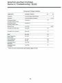
Tabte 3-1 HEATER PERFORMANCE SPECIRCATIONS
Setting
Specification
Low
Medium
Low
Medium
High
High
16,200
24,600
32,000
43,000
13,600
20,700
26,900
37,200
0.12
0.18
0.24
0.319
8-hrs/day burntime (5-gal. tank)
5.2days
3.5days
2.6days
2.0days
Continuous-use bumtime (5-gal.tank)
41.7hrs.
27.8hrs.
20.8hrs.
15.7hrs.
8-hrs/day bumtime (55-gal.tank)
57.3days
38.2days
28.6days
21.6days
Continuous-use bumtime (55-gal.tank)
19.1 days
12.7days
9.5days
7.2days
8-hrs/day burntime (275-gal.tank)
286.5days
191 days
143.2days
107.8days
Continuous-use bumtime (275-gal.tank)
95.5days
63.7days
47.7days
35.9days
Rating
Heater Output/hr.
.
Fuel Consumption (gal/hr)
28
MONITOR HEATING SYSTEMS
Section 3: Operation
— Circulation Fan Output: 176 cubic feet/min.
— Fuel source : Remote, separate tank(1.32 U.S.
gal., capsule tank optional)
— Potential heating area : 600-1200 sq. feet
*The energy from the combustion process is
released in the form of heat and vaporized water.
Normally, heating systems discharge water from
combustion to the atmosphere without condensing
it This 93% efficiency rating means that, assuming
the water cannot be condensed, 93% of the heat
produced by the combustion process is recovered.
Assuming the water can be condensed, the efficiency is 88%
3-3 INTRODUCTION
Monitor is an easy-to-operate vented kerosene
heater. Routine operation features high BTU output
automatic adjustment of room temperature, low fuel
and power consumption, and choice of automatic or
manual heater operation.
This section provides all information necessary to
operate the Monitor Heating System. All operation
procedures specified should be performed in the
order in which they are described.
3-4 OPERATING SPECIFICATIONS
The following specifications apply to the operation
of the Monitor 2200.
NOTE: Actual effective heating area depends upon
numerous factors such as type and severity
of climate, type of dwelling construction,
condition of dwelling, and thickness and
effectiveness of dwelling insulation.
— Rated Efficiency (as applied to kerosene
heaters): 93%*
— Rated Efficiency (as applied to central heating
systems): 88%
— Power Consumption : as follows
IGNITION
HIGH
MEDIUM-HIGH
MEDIUM-LOW
LOW
BURN
BURN
BURN
BURN
32watts
31 watts
250watts 41 watts 38watts
Table 3-2 lists Monitor 2200 performance specifications at various user-selected heat output settings.
Table 3-2 HEATER PERFORMANCE SPECIFICATIONS
Setting
Specification
Low
Medium
Low
Medium
High
High
Rating
9,600
12,400
17,400
22,000
Heater Output/hr.
7,970
10,290
14,440
18,260
Fuel Consumption(gal/hr)
0.07
0.09
0.13
0.164
8-hrs/day bumtime(1 .32-gal. tank)
2.4days
1 .Sdays
1 .Sdays
1. Delays
Continuous-use bumtime (1 .32-gal.tank)
18.9hrs.
14.7hrs.
10.2hrs.
8.0hrs.
8-hrs/day bumtime (55-gal.tank)
98.2days
76.4days
52.9days
41.9days
Continuous-use bumtime (55-gal.tank)
32.7days
25.5days
17.6days
14.0days
8-hrs/day bumtime (275-gal.tank)
491 days
382days
264days
210days
Continuous-use bumtime (275-gal.tank)
164days
127days
88days
70days
NOTE: Capsule tank cannot be used in Connecticut.
29
MONITOR HEATING SYSTEMS
Section 3: Operation
3-5 OPERATING CONTROLS AND INDICATORS
Several controls and indicators are used to operate
the heater and to monitor its performance as follows:
11
13
15
5
7 6 8
14
10
16
17
23(M-2200 3
only)
18
19
2
22
4
21
20
Fig. 3-1
ITEM NO
CONTROL OR INDICATOR.
FUNCTION
Iteml
OPERATION
Indicator Light
Light to indicate that power has been applied
to heater.
Illuminates when operation
ON/OFF
pushbutton switch is pressed to position ON
Item2
AUTO Indicator Light
Lights when heater runs in automatic mode.
AUTO, OPERATION, and appropriate BURN
Indicators are illuminated simultaneously
if heater is burning.
ItemS
ECONOMY PLUS
Indicator Light
Lights when heater runs in Economy Plus
mode.
Item4
CHILD LOCK
Indicator Light and
push-button switch
Lights when heater runs in CHILD LOCK
mode.
Items
BURN Status
Indicator Light
Lights when heater is burning.
(This light will turn on when the Solenoid
Pump is working.)
30
MONITOR HEATING SYSTEMS
Section 3: Operation
ITEM NO
CONTROL OR INDICATOR.
FUNCTION
ItemG
TEMP Indicator Light
Lights when heater is running and Digital
Window is showing the temperature.
Item/
AM Indicator Light
ItemS
PM Indicator Light
Item9
Digital Display
Indicates SET and ROOM temperature when
heater is running, and indicates time when
heater is Off.
Indicates time and temperature for automatic
operation setting.
Item 10
1th-4th
push-button switch
The automatic function allows the programming of different temperatures for different
times of the day. Two, three or four settings
can be used.
IMPORTANT: Once time and temperature
have been programmed, the
SET push-button switch must
be pressed with in 60 seconds.
Otherwise, time and temperature will revert to pre\iously
programmed time, if any.
Iteml 1
CLOCK SET
Indicator Light
Allows programming of current time when
illuminated.
NOTE: Prior to programming current time,
Digital Display shows 88:88.
IMPORTANT: Once current time has been
programmed, press the SET
pushbutton switch within 60
seconds. Otherwise clock display will revert to previously
programmed time, if any.
Iteml 2
WEEKLY
Indicator Lights
One of the lamp for the week, will turn on,
when setting the program for the selecting day
of the week.
Iteml 3
DAY SET
Indicator Light
When the program for the current day of the
week has been selected, the indicator light will
turn on.
Item14
TIMER SET
Indicator Light
When the timer program has been set, the
indicator light will turn on.
31
MONITOR HEATING SYSTEMS
Section 3: Operation
ITEM NO
CONTROL OR INDICATOR.
FUNCTION
Iteml 5
SELECT
push-button switch
This switch will be used for the selection of the
DAY SET, CLOCK SET, TIMER SET and also
for the day of the week (Mon, Tue, Wed, Thu,
Fri, Sat, Sun).
Iteml 6
TIME push-button
switch
This switch is used to set time and change
display over.
TEMP push-button
switch
This switch is used to set temperature and
change display over, in 2 degree increments.
Iteml 7
HOUR/DOWN
MINUTE/UP
repetitive-action
push-button switch
Programs time or temperature.
NOTE: Each time push-button switch is
pressed, the digit advances in increments of one digit, If push-button is
pressed and held, the digits are advanced repetitively.
Iteml 8
SET push-button switch
"Sets" time and/or temperature.
If this control is not pressed after time and/or
temperature have been programmed, the time
and/or temperature programmed (as indicated
by display window) will not be accepted, and
will revert to previously programmed time
and/or temperature.
Iteml 9
CLEAR push-button switch
Erases any programmed time and temperature.
When cleared, time and/or temperature previously programmed and displayed disappear(s)
from window.
IMPORTANT: Both current time and current
day of the week will have to be
reprogrammed if electrical operation is interrupted by power
failure or by disconnecting
heater plug from wall outlet
beyond 30 minutes. If this occurs, the heater will go into
MANUAL mode of operation.
Item20
ON/OFF push-button
switch
ON position (push-button is "in") applies power
to the unit. When this occurs, the OPERATION indicator light to Indicate that heater operation has begun.
OFF position (push-button is "out") remove
power from the heater. All circuits-except for
Clock and Air Flow — are shut down.
32
MONITOR HEATING SYSTEMS
Section 3: Operation
ITEM NO
CONTROL OR INDICATOR.
FUNCTION
Item 21
AUTO push-button
switch
Places heater in automatic mode of operation.
AUTO indicator lights to confirm automatic
operation.
Assuming that the heater has been properly
programmed and heater is in ON position,
heater will operate automatically.
When pressed again, AUTO indicator goes out
and then heater will operate in MANUAL
mode. During manual operation, the user turns
heater ON and OFF, at will.
When AUTO is disengaged, the unit will
operate on a manual temperature determined
by the AUTO setting for that time of day.
Item 22
ECONOMY PLUS
push-button switch
Places heater in Economy Plus mode of
operation. ECONOMY PLUS indicator lights
to confirm Economy Plus operation.
When pressed again, ECONOMY PLUS
indicator goes out and then Economy Plus
mode will be cancelled.
NOTE: Economy Plus mode is accepted only
in the MANUAL mode.
Item 23
EMPTY Indicator Light
In case of using the capsule tank, when the
fuel is empty, EMPTY Indicator Light blinks.
x/
3-6 PRE-OPERATION CHECK LIST
After heater installation, but prior to Monitor heater
start-up, inspect the system for operational readiness. The following check list specifies those items
that should be inspected on a routine basis:
x/
x/
Check that the Monitor heater is plugged into
wall outlet
(120 Vac, 60 Hz)
x/ Verify that adequate supply of kerosene is
available in fuel tank
\/ Confirm that fuel is free of water or other
contaminants
x/ Check fuel tank for good operating condition; it
must be free of rust, corrosion, and/or leaks
x/ Inspect Fuel Line for signs of leaks, loose
connections, cracks, air pockets or blockages
x/ Confirm that Fuel Valves on Fuel Tank and
Shut-off Valve are open so fuel can flow
freely
x/ Outside dwelling, check area immediately
around Flue Pipe for combustibles or obstructions to free air circulation
x/ Inspect Air Line for cracks, loose connections
or blockage
x/ Check Exhaust Line for cracks, loose connections or blockage
\/ At rear of heater, verify that air flow to the Air
Circulation Fan is not blocked
x/
Inspect dwelling interior and confirm that immediate area near heater is free of combustible
and objects that might interfere with free air
flow.
Make certain that Heat Sensor is not exposed
to drafts, direct sunlight, nor direct heat from
the Monitor.
Confirm that heater is level
If this inspection reveals any system deficiencies,
correct the problems before operating the heater.
3-7 OPERATION
Operation of Monitor heater can be controlled
manually by the user, or run automatically by the
microprocessor.
Paragraphs 3-8 through 3-12 provide the details of
heater start-up, operation, and shutdown. The
controls and indicatoes illustrated by Fig. 3-1 used to
operate the system and to monitor the heater's
performance.
33
MONITOR HEATING SYSTEMS
Section 3: Operation
2. Reducing heat loss during the prepurge and postpurge cycles.
3. Reducing inefficient combustion associated with
start up and shut down.
4. Prolonging component life by decreasing expansion and contraction of internal parts.
3-8 MANUAL HEATER OPERATION
Operation of the heater is under the direct control of
the user (heater will not operate automatically). The
heater will, however, automatically respond to changes in room temperature signaled by the Heat Sensor to maintain the temperature of the room at a
comfortable level.
NOTE: This feature could be compared to driving
an automobile in stop and go traffic (regular
mode) versus highway driving with cruise
control engaged (Economy Plus mode).
NOTE: Resetting the Fuel Constant Level Valve is
necessary only if the heater is being started
for the first time, hasn't been used for an extended period of time, or if tank has run
empty. If priming is unnecessary skip to step
2.
3-9 AUTOMATIC HEATER OPERATION
Automatic operation is established by programming
the time/temperature settings for specific times for
each day. On a daily basis, a maximum of four
time/temperature settings can be programmed.
STEP1: Prime the Heater
Gently press and release the Fuel Constant Level
Valve Reset button two or three times.
If, subsequently, it should be desired to switch to
manual mode of operation, the changeover can be
made at any time.
STEP2: Select Manual Opereation
If heater operation is in AUTO mode, press the AUTO
push-button switch and change Auto to Manual
mode.
Proceed with automatic mode of operation in the following manner:
STEP3: Select Temperature Setting
After pressing the TIME/TEMP push-button switch to
indicate the Set Temperature and Room Temperature
in the display window, press either the UP or DOWN
push -button switch to set the digital set room temperature indicator to the desired temperature, and
then press the SET push-button switch.
Stepl: Set the Day of Week
Press the "SELECT" Button, at which time the "DAY
SET' Light will illuminate. The "Mon" Light will illuminated and flash at this point.
Illuminate and flash the light of the current day of the
week (e.g.; "Wed") by pressing the "UP" or "DOWN"
Button, and then press the "SET1 Button to lock into
memory. The current day (e.g.; "Wed") light will illuminate continuously.
IMPORTANT: In case no temperature is set, temperature will automatically be set
at the initial set temperature.
Step2: Set the Time
Press the "SELECT" Button, at which time the
"CLOCK SET" Light will illuminate. The LED indicator in the Display Window will show 88:88 at this
point.
STEP4: Turn Monitor On
Press the ON/OFF push button switch to position
ON. The operation indicator light illuminates to indicate that- power has been applied to the instrument
and the heater is cycled for manual mode of operation.
Step3: Set the Hour
Press the "HOUR" Button until the correct hour
(either A.M. or P.M.) appears in the window.
NOTE: The 'HOUR' and 'MINUTE' Buttons can be
pressed and held or pressed momentarily to
change the time.
INSTRUCTIONS FOR ECONOMY PLUS MODE
To engage the economy plus mode, simply press
down the button labeled "Economy Plus", to disengage press again.
Step4: Set the Minute
Press the "MINUTE" Button until the correct time appears in the window.
Immediately press the "SET" Button.
NOTE: If the 'SET' Button is not pressed within
Iminute after the time set, the programming
will be cancelled.
NOTE: Operation switch must be "ON" and in MANUAL mode.
This feature minimizes the "ON" and "OFF" cycling of
the unit by allowing it to overshoot the set temperature by 8 degrees instead of the normal 4 degrees.
The advantages of this feature are to increase the
overall efficiency of the unit by:
1. Decreasing electrical consumption by decreasing
the frequency of ignition cycles.
34
MONITOR HEATING SYSTEMS
Section 3: Operation
Follow same steps as above, set the programs of
Tuesday. Set the programs of remaining days in the
same manner.
3-10 PROGRAMMING THE WEEKLY TIMER FOR
AUTOMATIC HEATER OPERATION
The Monitor 2400/2200 Heating System is capable
of providing up to 4 different temperature setting for
4 different times of each day of the week. Not all 4
settings have to be used; 2, 3 or 4 settings can be
used. A clear understanding of programming temperatures, time and day of the week from the previous pages is needed before programming the automatic settings. Also, the present time and the day of
the week must.have been set.
This system is capable of programming Monday to
Friday, Saturday and Sunday to same 4 programs as
shown in the table or each day can have a different
set of 4 programs. Also, this system is capable of
programming all 7 days to have the same set.
Suggested weekday and weekend programs are
shown below;
Step4: Setting the program by using Copy function Tuesday - Friday
You can easily duplcate Monday's program for the
remainder of the week, or any group of days, by using the Copy function.
After having set the program for Monday, press the
"1st-4th" Button until "COPY" flashes in the LED display window. Note that "Mon" is also flashing in the
Weekly Timer Control panel. To copy Monday's program to Tuesday, press the "UP" or "DOWN" button
to flash the Tue" light. Both "Mon" and Tue" lights
are flashing.
Press the "SET" button, and Tue" is steady, and
"COPY" and "Mon" lights are flashing.
Next. Press the "UP" or "DOWN" button to illuminate "Wed" and then press "SET". Tue" and "Wed"
are both steady, but "Mon" and "COPY" are flashing.
Repeat the above sequence for Thu" and "Fri".
Then hold down the "SET" button for 3 seconds, or
until you hear the "BEEP" and observe that 'COPY"
stops flashing. The programs for Tue, Wed, Thu, and
Fri are now copied and set.
In about 10 seconds, only "Mon" will be flashing.
Press the SELECT button to select the current day,
and the TIME will appear in the display window.
Suggested Programs
Mon - Fri
1st
2nd
3rd
4th
Sat - Sun
1st
2nd
3rd
4th
Time
6:00 AM
8:30 AM
5:00 PM
11:OOPM
Temperature
Time
7:00 AM
Temperature
68'F
60'F
68T
58T
10:00 AM
4:00 PM
1 1 :00 PM
68T
60' F
68T
58'F
Saturday - Sunday
Follow same steps as above to set the "Saturday"
program. (Steps 1 and 2)
Press "1st-4th" button until "COPY" flashes in the
display window.
Press the "UP" or "DOWN" button to illuminate "Sun"
which will flash.
Press "SET" button and "Sun" will light steady.
Then, press "SET" button for 3 seconds, or until you
hear the "BEEP" sound and "COPY" light stops
flashing.
The Sunday program has been copied from Saturday.
Stept: Seting the 1st program of Monday
Pressing the "SELECT" Button will illuminate the
"TIMER SET" Light. The "Mon" Light will illuminate
and flash, and the TIMER SELECTOR" LED indicator in the Display Window will show" 1" at this point.
Pressing the "TIME/TEMP" Button will illuminate the
":" Light in the Display Window, and then set the 1st
desired time by pressing the "HOUR" and "MINUTE"
Buttons. Once the desired time "AM or PM" is displayed, press the "SET" Button to lock into memory.
Press the "TIME/TEMP" Button again. Set the desired temperature for the 1st time setting by using
the "UP" and "DOWN" Buttons. Once the desired
temp is displayed, press the "SET" Button to lock
into memory.
StepS: Activate Automatic Operation
For the heater to operate on automatic once the settings are in memory, simply press the "AUTO" Buttton on the control panel. The "AUTO" Light will illuminate to confirm the heater is in the automatic
operation mode. The heater will now maintain the
programmed temp for that time of day of the week.
Step2: Setting the 2nd, 3rd and 4th programs of
Monday
Pressing the "1st-4th" Button will show "2" at the
TIMER SELECTOR" LED indicator
in the Display Window.
Follow same steps as above, except for 2nd
time/temp, (ie; 2nd 8:30 AM 60T)
Repeat 3rd and 4th settings by same steps.
IMPORTANT: The heater will not operate in automatic unless the ON/OFF switch is in
the "ON" position.
Step6: Clearing An Automatic Setting
If you wish to clear any automatic setting, press the
"SELECT" and "1st-4th" Button to the appropriate
setting and press the "CLEAR" Button. A new setting will need to be entered otherwise the old setting
will return after 1 minute.
StepS: Setting the programs of Tuesday - Sunday
Pressing the "SELECT" Button will illminate and
flash the "Tue" Light, and the TIMER SELECTOR"
LED indicator in the Display Window will show "1" at
this point.
35
MONITOR HEATINGSYSTEMS
Section 3: Operation
ation before power interruption, the initial setting
temperature (60°F) in case of automatic operation
before power interruption.
When the heater resumes operation, The Display
Window will show 88:88 indicating the need to reset
the clock and the day of the week for automatic operation.
3-11 HEAT SENSOR
Heat Sensor is located on the rear of the cabinet. It
is recommended to leave the sensor in its original
mounted position. However should relocation be
necessary, choose a location for the sensor that is
not in the path of direct sunlight, drafts or the flow of
warm air from the heater. Loosen the screw and release the sensor from the rear of the cabinet. Fasten the sensor to the wall with the screw.
CHILD LOCK:
NOTE: The CHILD LOCK will help to prevent accidental operation as well as small children
from altering controls.
3-12 MONITOR SHUTDOWN
A simple one-step procedure is utillized to shutdown
the Monitor.
Press ON/OFF push-button switch to position OFF;
the OPERATION indicator will extinguish.
To operate the CHILD LOCK simply hold the "CHILD
LOCK" Button down for 3 seconds, or until you hear
two short beeps. The function is activated immediately and the "CHILD LOCK" Light will illuminate.
To deactivate the CHILD LOCK simply hold the
"CHILD LOCK" Button down for 3 seconds, or until
you hear two short beeps. The "CHILD LOCK" Light
will go out.
The lock can be deactivated at any time in this way.
IMPORTANT: Once heater has shut down, it cannot be restarted until post-purge
cycle has been completed. If
ON/OFF switch is left in position
ON, Monitor operation will automatically restart upon completion
of post-purge.
During normal operation the CHILD LOCK may be
activated and all controls other than the OFF switch
will be locked. Deactivating the lock releases the
controls. If the lock is activated while the heater is
turned OFF, then all functions will be locked. If the
heater is Turned OFF while the CHILD LOCK is activated, if cannot be turned ON again until the lock is
deactivated.
3-13 OUT OF FUEL
During either manual or automatic operation of heater, fuel in the tank may be depleted.
The Monitor is known to be out of fuel when all of
the following symptoms are present:
— The code.F E14J is indicated in the display window.
— Absence of flame (visually verified through view
plate on wall of Combustion Chamber).
3-15 RECOVERY FROM OVERHEAT CONDITION
The Monitor is protected against damage resulting
from an overheat condition by two 115'C automatic
reset thermostats.
In the event of an overheat the thermostats are triggered to cut off the .flow of kerosene to the Burner
Pot, the flame is extinguished automatically, and
user is alerted to the overheat condition by indicating
the code "E14" in the display window.
To recover from an overheat condition, proceed as
outlined below:
STEP1: Turn Heater OFF
Press ON/OFF switch to OFF.
STEP2: Fill Fuel Tank
A. Close shut-off valve at outlet of Fuel Tank.
B. Drain Fuel Tank (from bottom, if possible) to remove all condensation, debris, and old fuel.
C. Fill Tank with fresh, crystal clear kerosene.
D. Upon completion of stepC, open shut-off valve
which was closed in stepA above.
STEP1: Turn OFF Heater
STEP3: Turn Heater ON
Press ON/OFF switch to ON. Proceed with normal
heater operation.
STEP2: Allow Monitor Heater to cool
NOTE: Be sure that heater is cool to touch.
3-14 RECOVERY FROM A POWER FAILURE
If power to the heater is interrupted, a thud-like noise
may be heard in the combustion chamber. This is
normal, and should not cause alarm.
For power interruptions of up to 30 minutes, the set
memory is kept and will resume operation automatically with the set memory.
For power interruptions beyond 30 minutes, your
heater will resume operation (after a 3 minutes cool
down period) in the MANUAL mode and maintain
room temperature according to the previous setting
temperature you've selected in case of manual oper-
A period of 30 to 45-minutes should be sufficient to
permit heater to cool completely.
STEP3: Unplug Heater
Disconnect neater power cord from wall outet.
36
MONITOR HEATING SYSTEMS
Section 3: Operation
STEP4:
NOTE:
3-16 RECOVERY FROM BLOWN FUSE MOVE TO
TOP OF NEXT COLUMN
Check for Cause of Overheating
Overheating is usually caused by objects
All electrical components of the Monitor heater protected against power overloads and electrical malfunctions by a 2-amp fuses and a 10-amp fuse.
Should a fuse blow, the recovery procedure in outlined below:
that impede free air circulation.
Look for debris and other obstructions at front of
heater, at Circulation Fan at rear of the heater, and
at Flue Pipe tip outside dwelling.
STEP1: Turn Monitor OFF
STEP2:
STEPS:
STEPS:
Unplug heater
Remove Front Cover and Louver Assembly.
STEPS: Remove Front Cover.
Clean Heater Interior.
STEP4: Remove Louver Assembly.
STEPS: Locate and replace fuse(s) Replace fuse
with same type and rating never oversize fuse.
WARNING:
BEFORE PROCEEDING TO CLEAN HEATER, BE
SURE THAT HEATER INTERIOR IS COOL ENOUGH
TO TOUCH.
STEP6:
Reattach front cover
(Be sure that the connector is connected to the printed circuit board.)
With a clean, lint-free, damp rag or other appropriate
cleaning material, wipe up all dust, dirt and debris
from exterior of cabinet, including exterior of Combustion Chamber and Heat Exchanger.
STEP7:
Reattach Louver Assembly and Front
Cover.
STEPS:
Plug heater power cord into wall outlet.
STEPS:
Turn Monitor ON
STEP7:
STEPS:
STEP9:
Replace Louver Assembly and Front
Cover.
STEP10: Reprogram heater
Reconnect Monitor Heater Power Plug to
the Wall Outlet
Turn Heater ON
STEP11: Program Automatic operation cycles (if
applicable)
STEP12: Select Automatic operation (if applicable)
STEP10: Reprogram Heater Microprocessor
STEP11: Select Mode of Operation
CAUTION:
Should fuse blow again, unit should be checked
for shorted component failure, or PWB failure.
If after the completion of recovery
procedure, the heater overheats
again, something is wrong/
Do not operate heater until problem has been diagnosed and cor
reded
37
MONITOR HEATING SYSTEMS
Section 3: Operation
38
o
-o
m
DO
o
o
33
O
W
—
1
Xj
m
MONITOR HEATING SYSTEMS
Section 4: Maintenance
cally in order to sustain the efficiency of the Monitor
Heating Systems.
4-1 INTRODUCTION
Heater maintenance is divided into two classifications; periodic maintenance is required to maintain
the heater in good operating condition; corrective
maintenance is necessary to repair a malfunction.
At the time of the demonstration or installation,
heater maintenance should be discussed with the
user; emphasize that a clean heater and proper fuel
are the keys to optimum heater operation and
performance.
4-2 PERIODIC MAINTENANCE
The Maintenance Schedule provided in Table 4-1
describes the tasks that must be performed periodi-
Table 4-1 SUGGESTED MAINTENANCE ACTIVITIES
Activity
Check all fuel pipes for leaks and
loose connections
Remarks
Material
OD copper tubing
Fuel piping must be secure and
free of leaks, Replace tubing
when necessary.
Inspect exhaust piping for leaks or
loose connections
All exhaust pipes must be covered
by a cloth insulation cover.
If cloth cover shows signs of
discoloration
at joints, check
o-rings.
Check fuel for water and/or other
contamination.
Fuel color should be clear, whether it's crystal clear or dyed red it
still should look clear not cloudy.
See Corrective Maintenance procedure paragraph 4-9.
Check and or replace fuel filter at
tank if dirty check and clean constant level valve strainer, if dirty
drain constant level valve, if dirty
check and clean strainer on internal
fuel pump. Inspect fusible link valve
input fitting if used. Clean only if
necessary verify heater in level.
Inspect flue pipe for obstruction or
corrosion. High sulfur fuels can
produce holes in exhaust portion of
flue pipe, especially in extreme
cold areas, where flue pipe condensation occurs.
If blocked, clean and vacuum.
If corroded badly, replace.
Inspect electrical wiring for cracks,
signs of deterioration, bare wires
and/or loose connectors
Clean heater
WARNING:
Clean, lint-free cloth and a mild
non-abrasive household cleaning
agent. USE ONLY
NONPETROLEUM
DISTILLATE
CLEANERS.
UNPLUG HEATER BEFORE PROCEEDING. HEATER MUST ALSO
BE COOL BEFORE STARTING.
Wipe down exterior of heater cabinet. Vacuum heater interior (if
necessary).
Clean Air Circulation Fan (Monthly)
Vacuum
blades.
Inspect air piping for leaks or loose
connections.
Inspect rubber Air Hose at rear of
heater.
Look for cracks, wear, or signs of
deterioration; replace if necessary.
Clean fuel constant level Valve
filter. Inspect fusible link Valve
input fitting.
Clean only if necessary, Verify that
heater is level.
Clean Kerosene
39
fan
cage.
Wipe
fan
Refer to paragraph 4-5. Procedure
is described in paragraph 4-6.
Check Leveling Guide.
MONITOR HEATING SYSTEMS
Section 4: Maintenance
Activity
Remarks
Material
Inspect Combustion Ring. Flame
Sensor Rod, Baffle, and Burner
Cloth.(Suggested frequency every
3 years).
Clean all carbon deposits. Replace
if excessively worn, warped, or
cracked.
NOTE: If any gaskets are torn
when Components are
removed, the gasket must
be replaced.
Clean Combustion Chamber (every
3 years)
Vacuum all carbon deposits from
interior of chamber.
Inspect air holes in Burner Pot
Use a small, stiff brush or a short
length of soft copper wire to clean
any blocked holes.
A glass beater works well if available.
Clean Igniter
Scrape any carbon deposits from
igniter.
Check air piping that interconnect
Combustion Blower and Air Pressure Switch.
Replace air piping that is worn,
broken or brittle.
Check for carbon build up in fuel
inlet going into burn chamber (every
3 years)
Check for carbon residue at burner
end of fuel line (every 5 years)
Disconnect copper fuel piping from
burn chamber and clear fuel inlet
line by reaming with a solid piece of
wire(such as copper.bailing wire.or
coat hanger) which should be able
to go in approximately 3" without
obstruction.
The fuel line can be checked and
cleaned with a thinner piece of wire.
NOTE: Removing and retightening
burner fuel connection
must be done when the
burner cools down completely. If it is done when
the burner is hot, the welding on the fuel joint may
break. Fixing torgue for
nut;30~40kg-cm(26
~35lb-in)
securely, especially at joints.
C. Turn heater ON.
D. Carefully apply a small amount of soapy water
(with a paint brush) to the surface areas of the
air/exhaust piping.
4-3 INSPECT EXHAUST/AIR PIPING
Verify that all exhaust and air pipes are free of leaks
and loose connections, as specified below:
STEP1:
Remove Protective Cloth
Remove cloth insulation cover(s) from all exhaust
pipes.
STEP2:
Any leaks that may exist will be readily
identified by the appearance of bubbles.
Inspection of Exhaust/Air Piping
A.
Visually inspect both air and exhaust piping for
obvious cracks, leaks, or loose connections.
Black carbon deposits may be evidence of
these leaks, and o-rings may need to be
replaced.
B. Be sure that all pipes are installed tightly and
40
STEP3: Return to Operating Condition
A. Turn heater OFF.
B. Dry all pipes with paper towels.
C. Repair any leaks that have been found (if
necessary, replace the tubing).
D. Replace cloth insulation covers.
MONITOR HEATING SYSTEMS
Section 4: Maintenance
4-4 VERIFY IGNITER OPERATION
Visually inspect Igniter Operation
WARNING:
CLOSE SHUT-OFF VALVE OF THE EXTERNAL
FUEL TANK TO AVOID DRAINING ALL FUEL
FROM TANKS.
WARNING:
HEATER IS OPERATIONAL DURING THIS INSPECTION. AVOID DIRECT CONTACT WITH ANY
HEATED OR ELECTRICAL COMPONENT.
NOTE:
STEP1: Prepare for Inspection
Remove Front Cover and Louver Assembly.
Power should be OFF during the performance of this procedure.
STEP1: Disassembly
A. Using a phillips head screwdriver, unscrew the
screws holding the rounded diamond-shaped
cover plate at the bottom of the Fuel Constant
Level Valve. Remove the cover plate.
STEP2: Visual Inspection
A. Turn heater ON.
B. Look (downward) through window on the Combustion Chamber. Verity that igniter is glowing.
NOTE:
If igniter does not glow, something is wrong.
Refer to the Troubleshooting Chart in Section 6
of this Service Manual to diagnose the problem.
C. An alternate inspection is to feel the igniter
cover after the unit has been in the ignition
stage for about 5 minutes. It should be warm.
Position a six inch U shaped piece of metal
or cardboard under strainer cover to drain
fuel into a pan.
B. Carefully remove the rubber gasket which is
located behind the cover plate.
STEP2: Inspection and Cleaning
A. Pull the filter straight out of the fuel reservoir.
B. If the filter is dirty (but undamaged), rinse the
filter in fresh, clean kerosene to remove all
particles. Replace damaged filters.
C. To drain off upper portion of fuel constant level
valve, back out phillips head screw which is
located slightly above and to the left of filter
cover plate. (See Fig4-1)
D. If upper portion drain is dirty or containing
water, then remove pump and inspect and
clean its screen.
CAUTION: If igniter is broken.do not operate the
"ON/OFF switch button repeatedly.
STEP3: Reassembly of Heater
Turn the heater OFF and replace the Louver Assembly.
4-5 CLEAN FUEL CONSTANT LEVEL VALVE FILTER
Note: Use a quality fuel filter at the tank to minimize
need for cleaning constant level valve filter, A
water separate type filter works well, and
avoid felt type filter elements.
Contaminants are trapped by the filter to prevent
them from clogging the Fuel Constant Level Valve.
STEPS: Reassembly
A. Push the (new or cleaned) filter back into the
bottom of the fuel reservoir.
B. Replace both the rubber gasket and the cover
plate. (Take care to properly align the screw
holes in the gasket and cover plate).
C. Wipe up any spilled fuel.
The filter, itself'has a great number of small pores.
Whenever a filter is torn or disfigured (enlarged
pores), it should immediately be replaced.
Inspect and clean the filter as indicated by the
procedure below:
Strainer
Strainer spring
Strainer
Cover
Constant Level Drain Guide
Valve
Container
Constanl Level
Valve Drain Screw
Figure 4-1 CLEAN FUEL CONSTANT LEVEL VALVE
41
MONITOR HEATING SYSTEMS
Section 4: Maintenance
4-6 CLEANING FUSIBLE LINK VALVE INTAKE
(In case of the Fusible Link Valve is mounted)
At periodic intervals, the fitting on the Fusible Link
Valve should be cleaned to prevent any accumulation of foreign materials from clogging the inlet This
is accomplished as follows:
STEP2: Installation of New Fuse
A. Install a new fuse into the fuseholder. The fuse
must be a 250-V, 2 amp or a 250-V, 10 amp type
as marked on the printed circuit board.
Do not use oversized fuses.
B. Replace the Louver Assembly and the Front Cover and plug the heater into the wall outlet.
.t. WARNING:
IMPORTANT: Whenever the heater is unplugged,
for more than 30 minutes, the microprocessor must be reprogrammed when power is restored.
UNPLUG THE HEATER. POWER TO THE HEATER
SHOULD BE OFF DURING THE PERFORMANCE OF
THIS PROCEDURE
STEP1: Close off Fuel Supply
A. 'Shut off fuel at the Storage Tank.
B. Manually turn handle to close Fusible Link
Valve.
NOTE: Place paper towels underneath the Fusible
Link Valve to catch any spilled fuel.
4-9 FUEL CONTAMINATION
Fuel contamination is often difficult to diagnose,
even though it will adversely affect heater operation
and performance. The best course of action to take
when fuel contamination is suspected is to examine
all of the system's fuel filters, beginning with the fuel
storage tank. If a Monitor Kerosene Lifter is part of
the fueling system, examine and clean that unif s
filter, as well as the filter located in the Fuel Constant Level Valve. When it has been determined tha
water or some other contaminants have infiltrated
the fuel, the following action must be taken:
STEP2: Clean Valve
A. Loosen hex nut on Fusible Link Valve inlet
fitting at rear of the heater. Disconnect the
copper tubing which delivers the fuel from the
storage or the fuel sump tank.
B. Using a small, straight piece of wire carefully
and slowly ream-out the inlet fitting on the
Fusible Link Valve.
A WARNING:
Avoid scratching the inside wall of the fitting.
With a cotton swab, wipe the interior area of the
inlet fitting.
BEFORE PROCEEDING FURTHER, UNPLUG THE
HEATER.
STEP3: Reconnect Fuel Line
A. Reconnect the copper tubing to the intake
fitting and tighten the hex nut
B. Turn ON fuel at Fusible Link Valve and at
storage tank.
C. Check for leaks.
STEP1: Remove Contamination
A. Shut OFF the fuel supply at the storage tank or
at the Fusible Link Valve.
B. Drain off the contaminants from the fuel storage
tank. Fill with fresh, clean fuel.
STEP2: Clean the Heater
A. Clean fuel cnstant level valve filter and filter
cmpartment.
B. Remove the Front Cover and Louver Assembly
and Solenoid Pump on the constant level valve.
Clean the Solenoid Pump filter.
4-7 CORRECTIVE MAINTENANCE
The two procedures below are remedies for very
generalized types of operating difficulties.
4-8 REPLACEMENT OF FUSES
A short circuit or similar electrical malfunction could
cause the fuse to blow. Troubleshoot the cause of
the blown fuse.
STEPS: Reinstall Cleaned Components
A. Replace the components correctly and install
new gasket
B. Turn on the fuel at the storage tank and at the
fusible link valve, and apply power to the heater.
If problem still exists and contaminated fuel is
suspected it can be checked by
A. Shutting off the fuel supply at the storage tank
and at the fusible link valve.
B. Drain off fuel at constant level valve.
C. Disconnect fuel-line at back of heater and hook
up a temporary tank with proven good fuel.
D. Test run heater to see if problem clears up with
use of new fuel.
Replace the fuse as follows:
WARNING:
DO NOT REPLACE FUSE WHILE POWER IS ON.
STEP1: Removal of Fuse
A. Unplug heater. Remove Front Cover and Louver
Assembly.
B. Remove the fuse from fuseholder on the Printed
Circuit Board.
42
MONITOR HEATING SYSTEMS
Section 5: Servicing
5-1 INTRODUCTION
Servicing is required when the Monitor Heater is not
running at proper efficiency. This section covers
possible causes and corrective procedures for efficiency loses.
Signs of improper heater efficiency and performance
would be:
— Yellowish lazy flame
— Smoke from flue pipe exhaust
— Heavy soot and carbon build up in combustion
chamber
— Lowered heat output.
5-2 MEASUREMENT OF FUEL FLOW RATE
Fuel flow rates are preset and sealed. These rates
should not and we recommend they do not be
readjusted.
The burner is assembled using gaskets to maintain
its air tightness. If these gaskets leak, the extra air
can cause a serious soot problem and or exhaust
gases to escape into the area being heated.
NOTE: If any gaskets are torn when components
are removed, replace. Disconnect power
supply to unit.
1. If cleaning is necessary, use the following method:
A. Remove Front Cover.
B. Remove Louver Assembly.
C. Remove Top cover and wire connectors.
D. Remove heat shield that covers combustion
chamber.
E. Remove service panel. (Optional)
F. Remove Flame detector rod. (Optional)
G. Remove fuel piping from bum chamber.
H. Remove gniter.
I. Remove screw at top of burner cap which attached it to cabinet. Remove screw at back of
cabinet from exhaust duct and remove the 1
screw holding the heat exchanger to base.
J. Remove the 6 screws holding the bum chamber
to base.
K. Rock chamber back and forth lightly, raise and
remove bum chamber and heat exchanger, as
one assembly from unit.
L. Set chamber upside down and remove the 4
screws which secure the burner pot to the burn
chamber. Pull the burner pot up and out.
5-3 REMOVAL OF WATER DEPOSITS AND
CONTAMINANTS FROM FUEL CONSTANT
LEVEL VALVE AND FUEL LINES
NOTE:
5-4 CLEANING THE BURN CHAMBER & BURNER
POT M-2400
Under normal running conditions, soot will not
deposit in great quantities inside the burner, and a
light covering of soot will not affect the performance
of the unit thus it need not be cleaned. However, if
heavy soot built up does occur the unit should be
opened and cleaned.
Disconnect the Monitor from power supply
(unplug) before proceeding.
1. Shut off valve of separate tank.
Bend a piece of sheet metal or cardboard into a
U shape and place it under the fuel constant
level valve strainer cover to drain bad fuel into
a 1-2 liter pan. (Figure 4-1)
A. Remove strainer cover and drain.
B. With strainer cover removed, inspect, clean
and/or replace strainer if damaged.
C. Remove drain port screw and drain.
D. Replace strainer, cover and screw.
E. Open fusible link valve or shut-off valve to
refill system with fresh crystal clear kerosene.
F. Repeat steps 1 -2 until all contaminated fuel
is drained off.
2. Remove fuel feed pipe from burner pot and
solenoid pump, and drain fuel into pan.
3. Once lines are clear, reconnect fuel feed pipe,
turn operation switch ON and start a test run.
NOTE: Removing and retightening burner fuel
connection must be done when a burner
cools down completely. If it is done when a
burner is hot, the welding on the fuel joint
may break. Fixing Torque for nut:30~40kgcm (26~35lb.in).
43
MONITOR HEATING SYSTEMS
Section 5: Servicing
2.
Turn counter-clockwise to remove combustion
ring. If ring does not turn, pull up slightly to
loosen retaining clips.
3. Use wire brush to clean inside of combustion
chamber.
Vacuum and wipe clean with a waste cloth.
4. If tar is present on the burner bottom, remove
the tar by using a flat-bladed screw driver or
wire brush.then clean the area by using a
vacuum cleaner etc.
NOTE: Make sure all air inlet openings are clear.
Apply glue at all 4 comers of Burner Cloth as Shown
in Figure 5-4.
Approx. 3/8"
5.
When cleaning the inside of the burner pot,
remove the igniter and change the burner cloth
by the following procebure.
NOTE: Bottom of burner pot must be clean for glue
to bond the cloth to the burner.
6. Apply glue arround the burner cloth as shown in
Figure 5-1.
3/16
3/16-
Burner Cloth
Figure 5-4
NOTE-//- Approx. 1/8-
Qlue
Approx. 1/16
7.
Figure 5-1
As shown in Figure 5-2 and 5-3, insert the
Burner Cloth narrow side between the Nozzle Collar and the Igniter Shield, then push
the Burner Cloth, using your fingers or a
screw driver, so that it slips in under the
Nozzle Collar. Afrerwards press and
straighten out the Burner cloth so that it is
glued flat and even on the Burner bottom.
NOTE: In some cases, pulling out the Fuel Nozzle
and Collar may make this procedure easier.
An easy out can be inserted into nozzle to
help break loose and remove it.
8.
9.
Combustion ring may deform and deteriorate
after several years use and should be cleaned
and inspected before reinstallation. If combustion ring is warped, has cracked or is deteriorating excessively it should be replaced.
When reassembling the unit check that combustion ring is positioned with the correct side
up and is sitting squarely on all three support
pins inside the burner pot.
Reassemble by reversing the procedure followed
during disassembly.
NOTE: Use of the economy plus feature can
minimize service calls and extend component
life.
Nozzle Collar
Figure 5-2
The Burner Cloth is not symmetrical in
shape, therefore make sure to place it in
the correct position so that the wider side
of the cloth is at left side of the Igniter
Shield as shown in Figure 5-4.
Figure 5-3
44
MONITOR HEATING SYSTEMS
Section 5: Servicing
NOTE: Make sure the position of flame detector rod is centered between combustion ring and burner pot
before reassembling. (See Figure 5-5)
Flame Detector Rod
Combustion Ring Assy
a*
V'
Combustion
Chamber
Gap
4mm(0.16") or more
Burner
Figure 5-5
NOTE: If flame rod is sooted or has a carbon coating it can be cleaned with steel wool or a
find sand paper.
For minor adjustments of flame detector rod without
disassembling any components:
1. Loosen the two retaining screws about half to one
full turn.
2. Tightening down on the top screw first will cock
the rod outward away from the combustion ring.
Tightening the bottom screw first will cock the rod
inward towards the combustion ring.
5-5 CLEANING THE FUEL INLET
When cleaning the combustion chamber and the
burner pot, the fuel inlet nozzle should also be
cleaned. This can be done as follows:
2. Push a piece of wire (about the same size as the
I.D. of fuel inlet pipe) into the fuel inlet nozzle.
3. If obstruction is felt twist wire back and forth (to
brake up soot and carbon) so that wire ultimately
penetrates igniter shield.
1. Disconnect copper fuel line at bum chamber.
45
MONITOR HEATING SYSTEMS
Section 5: Servicing
5-6 CLEANING THE BURN CHAMBER & BURNER
6.
POT M-2200
Apply glue (P/No.8217) on the burner bottom as
shown in Figure 5-6.
Under normal running conditions, soot will not
deposit in great quantities inside the burner, and a
light covering of soot will not affect the performance
of the unit thus it need not be cleaned. However, rf
heavy soot built up does occur the unit should be
opened and cleaned.
Burner Cloth
The burner is assembled using gaskets to maintain
its air tightness. If these gaskets leak, the extra air
can cause a serious soot problem and or exhaust
gases to escape into the area being heated.
NOTE: If any gaskets are torn when components
are removed, replace. Disconnect power
supply to unit.
Glue
Figure 5-6
Put the burner cloth on the burner bottom,
afterwards press and straighten out the
burner cloth so that it is glued flat and even
on the burner bottom.
1. If cleaning is necessary, use the following method:
A. Remove Front Cover.
B. Remove Top cover and wire connectors.
C. Remove heat shield that covers combustion
chamber.
D. Remove Flame detector rod. (Optional)
E. Remove fuel piping from bum chamber.
F. Remove igniter.
G. Remove screw at top of combustion. chamber
which attached it to cabinet. Remove screw at
back of cabinet from exhaust duct.
H. Remove the 4 screws holding combustion chamber to bum chamber.
I. Raise about 1/2" and remove combustion chamber and heat exchanger, as one assembly from
unit.
J. Remove the 4 screws holding the bum chamber
to base.
K. Set chamber upside down and remove the 4
screws which secure the burner pot to the bum
chamber. Pull the burner pot up and out.
2. Turn counter-clockwise to remove combustion
ring. If ring does not turn, pull up slightly to
loosen retaining clips.
3. Use wire brush to clean inside of combustion
chamber.
Vacuum and wipe clean with a waste cloth.
4. If tar is present on the burner bottom, remove
the tar by using a flat-bladed screw driver or
wire brush, then clean the area by using a
vacuum cleaner etc.
NOTE: Make sure all air inlet openings are clear.
5. When cleaning the inside of the burner pot,
remove the igniter and change the burner cloth
by the following procedure.
NOTE: Bottom of burner pot must be clean for glue
to bond the cloth to the burner.
7. Combustion ring may deform and deteriorate
after several years use and should be cleaned
and inspected before reinstallation. If combustion ring is warped, has cracked or is deteriorating excessively it should be replaced.
8. When reassembling the unit check that combustion ring is positioned with the correct side
up and is sitting squarely on all three support
pins inside the burner pot.
9. Reassemble by reversing the procedure followed during disassembly.
NOTE: Use of the economy plus feature can
minimize service calls and extend component life.
46
MONITOR HEATING SYSTEMS
Section 5: Servicing
NOTE: Make sure the position of flame detector rod is centered between combustion ring and burner pot
before reassembling. (See Figure 5-7)
Combustion Ring Assy
Flame Detector Rod
Bum
Chamber
Gap
3mm(0.12") or more
Burner
Pot
Figure 5-7
NOTE: If flame rod is sooted or has a carbon coating it can be cleaned with steel wool or a
find sand paper.
For minor adjustments of flame detector rod without
disassembling any components:
1. Loosen the two retaining screws about half to one
full turn.
2. Tightening down on the top screw first will cock
the rod outward away from the combustion ring.
Tightening the bottom screw first will cock the rod
inward towards the combustion ring.
5-7 CLEANING THE FUEL INLET
When cleaning the combustion chamber and the
burner pot, the fuel inlet nozzle should also be
cleaned. This can be done as follows:
2. Push a piece of wire (about the same size as the
I.D. of fuel inlet pipe) into the fuel inlet nozzle.
3. If obstruction is felt twist wire back and forth (to
brake up soot and carbon) so that wire ultimately
penetrates igniter.
1. Disconnect copper fuel line at bum chamber.
47
MONITOR HEATING SYSTEMS
Section 6: Troubleshooting | M-2400
Resistance values
COMPONENT
APPROX. OHMS
Igniter (connector B/ B)
12.7
Power Transformer—Primary (AC 120V) "Blue" & "Blue" Connector H
141
Power Transformer—Secondary (AC 12V) "Yellow" & "Yellow" Connector R
1.9
Power Transformer—Secondary (AC 120V) "White" & "White" Connector R
590
Circulation Fan (LEAD WIRE "WHITE "&" BLACK")
124
Circulation Fan (LEAD WIRE "BLACK "&" BLUE")
270
Combustion Blower (LEAD WIRE "WHITE "&" GRAY")
41
Combustion Blower (LEAD WIRE "GRAY "&" ORANGE")
78
Thermistor (connector Q/Q, at 77' F)
10,000
Fuse 2A (read with fuse out)
0.1
Fuse 10A (read with fuse out)
0.01
Solenoid Pump (Bypass resistor at pump and read accross coil)
565
WARNING:
DISCONNECT HEATER FROM POWER SOURCE
BEFORE MAKING ANY RESISTANCE TESTS.
49
MONITOR HEATING SYSTEMS
Section 6: Troubleshooting | M-2400
Component Voltage Readings
COMPONENT
READING TAKEN AT
Thermistor
Q on PCB Sensor disconnected
Thermistor
Q on PCB Sensor connected
Air Pressure Switch/
Overheat Protector Closed
Connector J
Air Pressure Switch/
Overheat Protector Open
Connector J
Solenoid Pump
K on PCB
Circulation Fan High Speed
WH to BK
110
Circulation Fan Low Speed
WH to BK
91
Igniter
Bon PCB
110
Power Transformer
(primary side)
AC 120V
110
Power Transformer
(secondary side)
AC 120V
AC 12V
120
12
Combustion Blower
High Speed
F on PCB
80
Combustion Blower
Low Speed .
F on PCB
41
AC
DC
1.5-3.2
110
pulse*
* Pulse can only be measured with a high impedance digital volt meter.
50
MONITOR HEATING SYSTEMS
Section 6: Troubleshooting | M-2200
Resistance values
COMPONENT
APPROX. OHMS
Igniter (connector B/B)
16.8
Power Transformer-Primary (AC 120V) "Blue" & "Blue" Connector H
141
Power Transformer-Secondary (AC 12V) "Yellow" & "Yellow" Connector R
^.9
Power Transformer—Secondary (AC 120V) "White" & "White" Connector R
590
Circulation Fan (LEAD WIRE "RED " & " BLACK")
430
Circulation Fan (LEAD WIRE "BLACK " & " YELLOW")
420
Combustion Blower (LEAD WIRE "BLACK" & " BLACK")
112.
Thermistor (connector Q/Q, at 77'F)
10,000
Fuse 2A (read with fuse out)
0.1
Fuse 10A (read with fuse out)
0.01
Solenoid Pump (Bypass resistor at pump and read accross coil)
990
WARNING:
DISCONNECT HEATER FROM POWER SOURCE
BEFORE MAKING ANY RESISTANCE TESTS.
Component Voltage Readings
AC
COMPONENT
READING TAKEN AT
Thermistor
Q on PCB Sensor disconnected
Thermistor
Q on PCB Sensor connected
Air Pressure Switch/
Overheat Protector Closed
Connector J
110
Air Pressure Switch/
Overheat Protector Open
Connector J
0
Solenoid Pump
K on PCB
Circulation Fan High Speed
RD to BK
110
Circulation Fan Low Speed
RD to BK
90
Igniter
Bon PCB
110
Power Transformer
(primary side)
AC 120V
110
Power Transformer
(secondary side)
AC 120V
AC 12V
120
12
Combustion Blower
High Speed
F on PCB
Combustion Blower
Low Speed
F on PCB
DC
5
1.5-3.2
pulse*
80
62
* Pulse can only be measured with a high impedance digital volt meter.
51
MONITOR HEATING SYSTEMS
Section 6: Troubleshooting
TEST POINT VOLTAGE
\Operation
\Mode
Preparation
Igniting
Pre-purge
Pre-heat
low med 2 min.
Pre-burning 1
(C.F.M:Off)
Pre-burning 2
(C.F.M:Low)
Test PointN,
TP2
5V±10%
5V±10%
5V±10%
5V±10%
5V±10%
TP3
12V±30%
12V±30%
12V±30%
12V±30%
12V±30%
TP4
1.5-3.2V
1.5-3.2V
1.5-3.2V
1.5-3.2V
1.5-3.2V
TP5
pulse
pulse
pulse
pulse
pulse
TP6
OV
OV
infinitly
variable
1.2V min.
1.2V min.
TP7
pulse at
plugin
5V
5V
5V
- 5V
\0peration
\Mode
High
Medium-High Medium-Low
Low
OFF
Waiting until
Programmed
Post-purge
time comes on
Test Point\
TP2
5V±10%
5V±10%
5V±10%
5V+10%
5V±10%
5V±10%
5V±10%
TP3
12V±30%
12V±30%
12V±30%
12V±30%
12V±30%
12V±30%
12V±30%
TP4
1.5-3.2V
1.5-3.2V
1.5 —3.2V
1.5 —3.2V 1.5-3.2V
1.5—3.2V
1.5~3.2V
TP5
pulse
pulse
pulse
pulse
pulse
pulse
pulse
TP6
1.2V min.
1.2V min.
1 .2V min.
1.2V min.
OV
infinitly
variable
OV
TP7
5V
5V
5V
5V
5V
5V
5V
52
GENERAL CHECKS
Is power available in wall outlet?
Is power Plug inserted in wall outlet?
Has there been a power interruption? (Display
window shows 88:88)
Has Circulation Fan stopped?
Is fuel in tank? Tank valve open?
Has Fuel Constant Level Valve Set Lever press and roiMro?
Is Operation Switch on?
Is Deration mode on Manual?
Is set temperature in High position?
Is Shut-off Valve 'open1 ?
Is child lock feature engaged (disengaged)?
SYMPTOM
CHECK1
RESULT
No ignition
CHECK2
-
I RESULT I
•
CHECKS
RESULT
CHECK4
RESULT
CHECKS
RESULT I
REASON
Is Igniter red?
Check visually
through the
Combustion
Chamber
viewing window,
of feet igniter
cover (after3.5
minutes prepurge preheat it
shuld be warm
to the touch.
lamp lit?
CORRECTIVE MEASURE
Falure of Circuit Board
-
Replace or check Circuit Board.
Incorrect wiring of Flame
sensor or Ground.
—
Correct wiring.
Flame sensor rod touches
to burner parts.
Correct or Change.
—
Soot adhering to combustion
chamber interior.
Failure of solenoid Pump.
I
L
—
I
I
n
Dins on circuit board?
2. Remove Igniter.
3. Disconnect wiring
for Solenoid
Pump.
Failure of Sotenoid Pump.
Replace Solenoid Pump.
Has constant level
valve safety tripped.
Reset the fuel constant level
valve.
Igniter glows but not all
the way around, partial Failure.
Replace Igniter
Failure of Igniter.
Is there 1 1 0V
-
Replace Sotenoid Pump.
1 Replace Air Pressure Switch.
Failure of Air Pressure Switch.
-
Clean gently with brush, etc.
I
Replace Igniter.
Failure of Circuit Board.
Replace or check Circuit Board.
Incorrect wiring.
Correct wiring.
Is there 1 10V or more at plug.
Failure of Igniter relay on
PCB replace board.
Failure of Circuit Board.
Replace or check
Circuit Board.
4. Operation Switch ON.
4
N.
dowlrt?
"-[
I
Melted. I
1
Change fuse,
plug it power
cord.
Fuse open.
Short circuit of lead wire.
r—
"
1
—I Change fuse.
I Correct or change.
L
Failure of Circuit Board.
.
op
Board.
—-I Put in Manual-Burn Mode.
CORRECTIVE MEASURE
REASON
Open valve.
Shut-off Vah/e closed
Tripped safety on Fuel constant
level vafve.
Reset Fuel constant level
varve.
Burner joint dogged. (Fuel IJne
passageway into the Combustion
Chamber near base of Burner POL)
Clean burner joint
J-4
Pump strainer dogged
Clean pump strainer
Fuel not fed because of surface
tension of water.
Discharge water.
—
Water gathering in fuel tank.
] Failure of Solenoid Pump.
Make General Checks above.
• Is fuel head too tow?
(See Section^ INSTALLATION)
• Is fuel line length correct?
• If using a Lifter, check Lifter
installation specifications.
• Is unit placed horizofi'talfy?
Correct or replace wires.
Airlock.
Straighten fuel line to remove air
pocket, or, correct fuel fine
installation.
Fuel not entering into valve.
Push Fuel Constant Level Valve
Set button 4 or 5 times.
Fuel shortage.
1. Push Operatin Button to "Off
2. Refuel tank.
3. Turn heater on.
heater.
(*ls not a failure, but is apt to occur)
1. Unplug heater
2. Remove air Mow obstructions and/
or determine cause of overheating.
3. Replace cover and restart heater.
—
Overheat condition.
—
Blockage inside valve
Clean needle valve and seat.
Air present in fuel fine.
Correct fuel line.
Failure of solenoid pump.
Pump strainer clogged
A
1 Replace Solenoid Pump.
Wiring failure.
Wiring Failure.
Poor flame, sounds of corn-
|
I Replace solenoid pump.
J-4
Clean Pump Strainer
I—I Correct Wiring.
Failure of solenoid pump.
Replace solenoid pump.
Failure of circuit board.
Replace or check circuit board.
r
tp
r—~.—'.
I
L| Rue pipe rotted.
rrectasspec
1
1
tighten all connection.
I
Inspect, and if rotted through.
P
PP«
SYMPTOM
_
duced when
set "High."
RESULT
CHECK1
placed horizontally level?
-1
Normal.
Is flue pipe too
long, or extension
kit has too many
bends.
(See Section 2,
INSTALL)
I
RESULT
CHECKS
Does
Combustion
Fan
work property?
CHECKS
RESULT
CHECK4
RESULT
•H N°™ai- - ?^^e r N-* - "jrp.wi -H
CHECKS
RESULT
Yes
according to
•specifications?'
- - aSSsss* T Y~ —
Process jumper wire'CJ'on P.W.
B. according to 'specifications'
1
intake or exhaust line dogged,
Is air damper
installed
according to
specifications?
L-l
Does flame
extend to
whole area
of burner?
kerosene?
Is Heater
mounted
horizontally?
t" '~ Clean out air and exhaust ducts.
Combustion fan failed.
Replace Combustion Blower
Assembly
Clogged air supply or exhaust piping.
Remove obstructions.
Not as specified.
1 Correct as specified.
Too much air flow.
Mount Air Damper
if needed.
Igniter does not get hot evenly
around igniter.
Replace Igniter
Combustion Ring is installed
improperly.
Install Combustion Ring properly.
Combustion Ring is broken or
wrapped.
Burner doth has come ungfuedreglue or replace burner doth and
regtue.
Normal. 1— See Symptom #5 above.
- Abnormal.
Chamber
Window gets
smoky after
running.
Clean pump strainer
Replace solenoid pump
Clean needed vatve and seat of
constant Level vatve
Install Air Damper and Blower
Damper according to
specifications.
-I Abnormal.
_|
Fuel solenoid pump malfunctioning.
(Makes a loud knocking noise.)
»
L
Is ignition
time too long?
(Usually 0.5-1
min.)
CORRECTIVE MEASURE
accoroiig to
'specifications''
Checlcfor
obstructions
(such as wasps
nests) in
exhaust or air
supply piping.
1
noise is made
soon after
igniting.
REASON
v
1
1
1 1 it " -r
property?
1
___| I
L
Is external
fuel tank too
tow? (See
Section2,
INSTALL.)
*- ... 1
Install Air
Damper and
Blower Damper
if needed.
(See Symptom
*5 above.)
1
Is there an
obstruction in
the Combustion
Air intake
System?
Lll
1
to High and Low 5-6
times.
_
—
^- Abnormal.
NO
Rame does not extend.
— J Air leaksfromIgniter Cover.
1
Supplies only small amount of
fuel due to dust or bubbles in
Fuel Delivery parts.
— Pump strainer is clogged.
Not as specified.
Replace gasket; correctly install
- cover.
nstruct customer about filter and
reset lever.
Clean pump strainer.
Correct as specified.
SYMPTOM
CORRECTIVE MEASURE
REASON
Is window
curtain too
dose to the
rear of unit?
is Circulation
Fan Guard
dusty?
Curtain or other obstruction
covers circulation air inlet.
dean guard.
Keep curtain from unit
H
No.
Does circulation fan Made
have heavy dust build up?
Are proper clearances being
maintained around unit
Remove obstacles to maintain
Failure of P.C.B
Replace or check P.C.8
Are garments being dried
on or in front of heater?
Circulation fan failed.
I
Replace Fan Motor.
Incorrect wiring.
I
Repair or replace wiring.
CHECKS
RESULT
REASON
CHECK4
CORRECTIVE MEASURE
Replace fuse.(F1)
NOTE : IF problem is found to be in PCB,
do not attempt to repair, replace
and send PCB thru your disttibutor to MPI for repair.
-
Failure of
transformer- 1.
—
Failure of dkxje.
(DS-D6)
-
Failure of capacitor.
(Oil)
Replace transformer-1.
Failure of IC2
Yes.
Failure of capacitor.
(C12)
~iI
Disconnect connector marked
CN1 Going to the SWITCH &
LAMP ASSY and then jump T1 to
TSofCNI on PCB.
"P.
YnYes.
1
-
Failure of resistor.
(R4&-FW9)
-
Failure of capacitor.
(C20.C21)
-
Failure of reset
switch.(SW)
1|
Failure of
resonator.(XL1)
Press the operation button
switch to ON position.
Failure of
resistor.(R7S)
Failure of
microprccessor.(IC1)
Failure of
SWITCH & LAMP ASSY.
Failure ot
microprccessor.(ICI)
Replace
SWITCH & LAMP ASSY.
SYMPTOM
CHECK1
RESULT
CHECK2
RESULT
CHECKS
RESULT
CHECK4
RESULT
CHECKS
CORRECTIVE MEASURE
REASON
n
No ignition.
Failure of
micfOprocessor.(ICl)
Failure of transistor
array.(IC12)
Failure of relay.
(RID
Fuse open.(F2)
Replace Fuse.(F2)
Igniter open.
Replace igniter.
Igniter is not evenly red
is there more
thanWdcTPS
andlC12
(®pin)?
Mo.
Ho
Replace igniter.
|
'
array.(ICl2)
-
•
-
-
J
Does solenoid
pump work?
1
M~
N
°-
(CS)
-
Incorrect wiring of
combustion biower.
Replace combustion
blower motor.
i
(D1.D1S)
microprocessor.flCl)
Failure of transistor
array.(lClO, IC12)
(E D
'
Failure of capacitor.
Failure of combustion
blower.
•^
A)
Failure of resistor.
(R4.R87)
-
Is there 160V DCL
at diode(D1)
(
Failure of triac.
(01)
-
Failure of resistor.
<R86)
Failure of photo
triac-(lCS)
|
—
Correct wiring.
SYMPTOM
REASON
CHECK1
CORRECTIVE MEASURE
(R5-R22 R103 R104)
—
—
—
—
—
—
"
.
Failure of capacitor.
(C6^8)
Failure of zener diode. (ZD1)
Failure o( diode.
(D2)
Failure of transistor.(Q2.Q3)
Failure of comparator.
(IC7)
Failure of transistor array.(IC12)
Failure of photo transistor.(!C6)
Failure of fuel supply parts.
Check fuel supply parts.
RESULT
CHECKS
RESULT
REASON
CORRECTIVE MEASURE
Failure of resistor.
(R25-R28)
Failure of transformer-!.
Replace transformer-!.
Failure of capacitor.
(C15-C17)
Failure of resistor.
(R23.R30-R32)
Failure of resistor.
(F136, R78)
Failure of capacitor.
(C33)
Failure of diode.
{D16, D18)
Failure of transistor
array.(IClO)
FLAME ROD BYPASS CIRCUIT
For testing purposes — A flame detector rod bypass circuit can be made up,
consisting of 2 insulated alligator dips, 2-6' pieces of insulated copper wire, 1-1
ampere 400 volt diode, and 1-1/4 watt 100K OHM resistor.
These components are to be soldered together in sequence as shown in
diagram below (note component and polarity).
Once the bypass circuit is made the unit is turned on, immediately after the
prepurge preheat cycle; when mode light comes on, the 0 and N pins are
disconnected off the PCB and replaced with the bypass circuit
The unit should then continue functioning as though it had a good flame inside
the bum chamber and service tests such as fuel flow can be checked.
(Note-WARNING. after all tests are completed, replace original flame rod wires
as it is a vital safety feature.)
m-
CLIPS
Failure of resistor.
(R33, R35)
Failure of microprocessor.(lCl)
Failure of wiring for flame
sensor and ground.
Correct wiring.
Incorrect installation of flame
sensor rod.
Correct installation.
Failure of comparator.(IC8)
CUPS
RESULT
CHECKS
RESULT
CHECK4
REASON
CORRECTIVE MEASURE
Failure of resistor.
(R64, R6S)
Failure of capacitor.
(027, C28)
Conned 10KQ resistor
at [Q] pins, and then,
set temperature from Low to High.
Failure of microprocessor.(tCI)
Failure of photo transistor. (1 Co)
Failure of transistor array.(1C12)
Failure of solenoid pump.
Replace solenoid
pump.
Failure of microprocessor.(ICl)
Failure of photo triac.(IC3)
Failure of transistor array.(IC12)
Failure of circulation fan motor.
Yes
Replace circulation
fan motor.
Failure of microprocessor (IC1)
Failure of transistor array.(IC12)
Failure of photo triac.(IC4)
Failure of triac.
(01)
Failure of resistor.
(R4, R87)
Failure of capacitor.
(CS)
Failure of combustion blower
motor.
Replace combustion
blower.
MONITOR HEATING SYSTEMS
Section 6: Troubleshooting
INDICATION OF FAILURE MODE
Digital Display
The Reason of Indication
Trouble Point
At pre-purge, Flame rod is sensing flame
when there should be none.
Flame sensing circuit, grounded flame
rod or pinched wire.
cnc
L UJ
After power is turned on, power supply to
the microprocessor timing circuit is
incorrect.
Timer clock circuit bad or power cycles
(hertz) to unit above or below acceptable
levels.
cnc
/_/_//_/
At starting of operation, the circuit to drive
photo triac of Solenoid Pump is
malfunctioning.
Solenoid Pump control circuit has a
malfunction.
Revolutions per minute of Combustion
blower is malfunctioning.
Combustion blower or Combustion blower
control circuit has a malfunction.
No ignition.
Failure of Igniter, Solenoid Pump or
circuit Board.
Incorrect wiring or flame rod touches to
burner parts.
Air pressure switch or overheat open.
Rame failure.
There are obstacles at circulation air inlet
or outlet.
Fan cage is clogged with dust.
Inadequate fuel supply.
Power supply voltage too low.
Voltage too low or Power detector circuit
has a malfunction.
Load failure of Combustion blower motor.
Flue Pipe is restricting airflow.
EDI
EDB
C O
L U
EH
C 1C
L IJ
C 1C
/_ IU
62
MONITOR HEATING SYSTEMS
Section 7: Electrical System
Schematics
63
Monitor 2400 : Room Heater products since February 2004
Monitor 2200 : All Room Heaters
J :: 3 i J. «• J.
icw IOM TiKTcie
TCJ
5XXXX X ><><>< )<)()<)<)
OOOC«)«)(!
1. Unless otherwise specified unit of capacitor
should b« uf and unit of resistor should be D.
2. unless otherwise specified resistor should be J type 1/10H
MONITOR HEATING SYSTEMS
Section 7: Electrical System IM-2400
Printed Circuit Wiring Diagram
CONNECTION OF LEAD WIRES
WEEKLY TIMER CONTROL
Tue
Wed Thu
8
O
t!
Sat
CD CD
SET
ROOM
CD BURN
TEMP
AM
Sun
LUS
RM
OPERATI
MYttT aoosEt nirasET TIMER SELECTOR
HOUR
MINUTE
(v)
DOWN
UP
Control Panel Printed Wiring Board
Fan
Thermostat
lo oi
P
|o|
1
Main Printed
Wiring Board
|o o o|
AC120V
Capacitor for
Circulation Motor
:=iJ | Dctgv
Transformer
"
Blower for
Circulation
K
W
M
N
SensorfThermistor)
TB
s
Blower for
Combustion
r
to
Pressure
Switch
B
j
Over Heat
Thermostat
A
" Ground
3
Pump
Heater
Figure 7-1 Monitor 2400
65
AC120V
60Hz
MONITOR HEATING SYSTEMS
Section 7: Electrical System IM-2200
Printed Circuit Wiring Diagram
CONNECTION OF LEAD WIRES
WEEKLY TWER CONTROL
^
O
SET
AM
PM
Control Panel Printed Wiring Board
Fan
Thermostat
Main Printed
Wiring Board
Cfc~o1
|o o o|
Capacitor for
Circulation Motor
—'Short
r— "| Terminal
p
Empty Lamp Switch
(Float Switch)
~o]
"
Blower for
Circulation
T1
TkH
K
fol
II loool
Flame Detector
T8
Blower for
Combustion
1
B
|0|
SensorfThermistor)
A
— Ground
Air
Pressure
Switch
Over Heat
Thermostat
AC120V
GOHz
Pump
Heater
Figure 7-2 Monitor 2200
66
MONITOR 2400
SERVICE PARTS LIST
MONITOR 2400 SERVICE PARTS LIST
ITEM
NO.
PART
NO.
1
6724
2
3
4
5
6
7
8
9
10
11
12
13
14
15
5019
6301
16
17
18
19
20
21
22
23
24
25
26
27
28
29
30
31
32
33
34
35
36
37
38
39
40
41
42
43
44
45
46
47
48
49
50
51
52
53
54
6302
6469
6470
6471
6725
6726
6357
6357A
6401
6363
6358
6311
6115
6402
6354
6403
6355
6119
6196
6313
6314
6122
6123
6176
6473
6164
6352
6353
6404
6124
6125
6405
6350
6317
6349
6356
6321
6727
6728
6729
6144
6730
6731
6461
6462
6732
6733
6172
6173
6734
6187
DESCRIPTION
SPILL TRAY
ADJUSTABLE LEG
AIR SUPPLY HOSE(A)
AIR SUPPLY HOSE(B)
Constant level valve only 1998 441/422
C.L.V. strainer 1998 441/422
Strainer gasket 1998 441/422
FUEL PIPE
SOLENOID PUMP
GASKET(1)
GASKET(1) RETAINING PLATE
BURNER
BURNER CLOTH
ROPE GASKET
HEATER(IGNITER)
GASKET(3)
IGNITER BRACKET
HEATER COVER PACKING
IGNITER COVER
FLAME DETECTIVE PLUG
PLUG PACKING
FL PLUG BRACKET
GASKET(4)
HEAT EXCHANGER ASSY
GASKET(6)
EXHAUST DUCT
O-RING(P39)
Oil sump pipe 1 998 M441
JOINT SEAL PACKING
FUEL NOZZLE
FUEL NOZZLE COVER
BASE TRAY RETAINER
WINDOW GASKET
WINDOW FRAME GASKET
WINDOW GLASS
WINDOW BASE GASKET
CHAMBER GASKET
COMBUSTION CHAMBER ASSY
COMBUSTION RING ASSY
CHAMBER CAP
CAPACITOR(3.0nF)
COMBUSTION BLOWER ASSY
SUCTION CASE A ASSY
SEAL PACKING
MOTOR FOR COMBUSTION
PWB ASSY
PWB SPACER CLIP(A)
PWB SPACER CLIP(B)
MICROPROCESSOR
BUZZER
FUSE(250V. 10A)
FUSE(250V, 2A)
FAN CAPACITOR(1 .5nF)(For Reference Only)
TR ARRAY(M54563P) IC10{For Reference Only)
67
ITEM
NO.
PART
NO.
DESCRIPTION
55
56
57
58
59
60
61
62
63
64
65
66
67
68
69
70
71
72
73
74
75
76
77
78
79
80
81
82
83
84
85
86
87
88
89
90
91
92
93
94
95
96
97
98
99
100
101
102
103
104
6254
6255
6257
6700
6722
6348A
105
6735
RELAY RL1 (For Reference Only)
TRIAC(Q1)(For Reference Only)
PHOTO TRIAC(IC3)(For Reference Only)
PHOTO TRIAC(IC4)(For Reference Only)
PHOTO TRIAC(IC5)(For Reference Only)
PHOTO COUPLER(IC6)(For Reference Only)
POWER TRANSFORMER
AIR LINE
AIR PRESSURE SWITCH
RUBBER BUSHING
OVER HEAT THERMOSTAT
FAN THERMOSTAT
POWER SUPPLY CORD
CORD BUSHING
CARRYING HANDLE
SENSOR ASSY
JOINT PIPE
AIR DAMPER(E)
AIR DAMPER(S)
AIR SUPPLY HOSE ASSY
EXHAUST OUTLET CAP
AIR PORT O RING
PIPE HOLDER
HOSE BAND
AIR OUTLET CAP
FLUE PIPE A/B
SLEEVE NUT
SLEEVE FLANGE SET
FAN BLADE
CIRCULATION MOTOR
BLOWER GUARD
WIRING GUARD
UNDER COVER
LOUVER
PLASTIC BUTTON PANEL
LAMP PANEL
CONTROL COVER
SWITCH & LAMP ASSY
FRONT COVER
TOP COVER
CABINET ASSY
WALL CLAMPS
SCREW SET FOR FLUE PIPE
CARTON BOX
CUSHION SET
OWNERS GUIDE
TOUCH-UP PAINT(WHITE)
GLUE
TOUCH-UP PAINT(M2400 GREY)
Combustion Blower Assy Nut
and Retaining Washer
Cabinet Screw Assortment
6701
6204
6702
6326
6703
6136
6704
6705
6706
4833
6707
6708
4004
6407
6408
6145
4014
4016
4006
4008
4805
8050
6723A
6148
6075
6709
6710
6455
6711
6712
6713
6714
6715
6716
6717
6718
6719
6194
6197
6720
6721
1157
8216
8217
MONITOR HEATING SYSTEMS
EXPLODED VIEWS AND PARTS LIST
68
M-2400
(97) Screw Set for Flue Pipe
(98) Carton Box
@) Touch-up Paint (White)
(99) Cushion Set
(fife Glue
Owners Guide
Touch-up Paint (Grey)
Cabinet Screw Assortment
MONITOR 2400 EXPLODED VIEW
(T
MONITOR 2200
SERVICE PARTS LIST
MONITOR 2200 SERVICE PARTS LIST
ITEM
NO.
1
2
3
4
5
6
7
8
9
10
11
12
13
14
15
16
17
18
19
20
21
22
23
24
25
26
27
28
29
30
31
32
33
34
35
36
37
38
39
40
41
42
43
44
45
46
47
48
49
50
51
52
53
54
55
56
57
PART
NO.
6740
5019
6741
6102
6742
6469
6470
6471
6744
6745
6164
6746
6747
6748
6749
6750
6358
6115
6277
6402
6117
6191
6751
6119
6196
6120
6752
6122
6123
6176
6124
6125
6786
6069
6753
6754
• 6130
6755
6702
6756
6134
6135
6757
6733
6172
6173
6901
6187
6254
6255
6257
6700
6701
6204
6758
6819
6703
DESCRIPTION
ITEM
NO.
PART
NO.
DESCRIPTION
SPILL TRAY
ADJUSTABLE LEG
AIR SUPPLY HOSE(A)
AIR SUPPLY HOSE(B)
FUEL PIPE
CONSTANT LEVEL VALVE only 1998 441/422
C.L.V. STRAINER 1998441/422
STRAINER GASKET 1998 441/422
SOLENOID PUMP
OIL SUMP PIPE
JOINT SEAL PACKING
FUEL SUMP
GASKET(1)
GASKET(1)RETAINING PLATE
BURNER
BURNER CLOTH
ROPE GASKET
GASKET(3)
HEATER(IGNITER)
IGNITER BRACKET
HEATER COVER PACKING
IGNITER COVER
FLAME DETECTIVE PLUG
PLUG PACKING
FL PLUG BRACKET
GASKET(4)
HEAT EXCHANGER ASSY
GASKET(6)
EXHAUST DUCT
O-RING(P39)
WINDOW GASKET
WINDOW FRAME GASKET
WINDOW PLATE
WINDOW GLASS
BURNER CHAMBER ASSY
COMBUSTION RING ASSY
CHAMBER GASKET
COMBUSTION CHAMBER ASSY
POWER TRANSFORMER
PWB ASSY
PWB SPACER CLIP(A)
PWB SPACER CLIP(B)
MICROPROCESSOR
BUZZER
FUSE(250V,10A)
FUSE(250V,2A)
FAN CAPACITOR(1.8uF)(For Reference Only)
TR ARRAY(M54563P)IClO(For Reference Only)
RELAY RL1(For Reference Only)
TRIAC(Q1)(For Reference Only)
PHOTO TRIAC(IC3)(For Reference Only)
PHOTO TRIAC(IC4)(For Reference Only)
PHOTO TRIAC(IC5)(For Reference Only)
PHOTO COUPLER(IC6)(For Reference Only)
BLOWER DAMPER
AIR LINE A
AIR PRESSURE SWITCH
58
59
60
61
62
63
64
65
66
67
68
69
70
71
72
73
74
75
6759
6771
OVER HEAT THERMOSTAT A
OVER HEAT THERMOSTAT B
FAN THERMOSTAT
AIR PACKING SET
POWER SUPPLY CORD
STRAIN RELIEF BUSHING
CARRYING HANDLE
SENSOR ASSY
COMBUSTION BLOWER ASSY
BLOWER MOUTH PACKING
SUCTION CASE
SEAL PACKING
BLOWER GUARD
CIRCULATION MOTOR
FAN BLADE
WIRING GUARD
WIRING HARNESS FOR FAN MOTOR
VENT CONNECTOR
AIR DAMPER(S)
AIR DAMPER(E)
AIR SUPPLY HOSE ASSY
EXHAUST OUTLET CAP
AIR PORT O RING
PIPE HOLDER
HOSE BAND
AIR OUTLET CAP
FLUE PIPE A/B
SLEEVE NUT
SLEEVE FLANGE SET
GASKET(7)
UNDER COVER
RQ
00
f5"7"7O
\j 1 1 £.
1\~^f\J
Ol l\/l—
VLR
fi
90
91
92
93
94
95
96
97
6773
6774
6775
6776
FRONT COVER
PLASTIC BUTTON PANEL
LAMP PANEL
CONTROL COVER
SWITCH&LAMP ASSY
TOP COVER
FUEL TANK COVER
CABINET ASSY
BODY CLAMP
Optional CAPSULE TANK KIT
FUEL TANK CAP
OIL FILTER
FLOAT SWITCH
FLOAT SWITCH PACKING
UNION NUT
BASE TRAY RETAINER
FUEL NOZZLE
SCREW SET FOR FLUE PIPE
CARTON BOX
CUSHION SET
OWNERS GUIDE
TOUCH-UP PAINT(WHITE)
GLUE
TOUCH-UP PAINT(M2400 GREY)
Cabinet Screw Assortment
BLOWER MOTOR
76
77
78
79
80
81
82
83
84
85
86
87
88
98
99
100
101
102
103
104
105
106
107
108
109
110
111
112
113
114
115
6761
6762
6763
6706
4833
6707
6708
6764
6141
6766
6144
6261
6767
6768
6263
6769
4004
6209
6770
6145
4014
4016
4006
4008
4805
8050
6723
6148
6806
6716
6777
6778
6779
6194
6760
6179
6177
6780
6781
6345
6782
6783
6197
6784
6785
1120
8216
8217
6722
6735
6765
MONITOR HEATING SYSTEMS
EXPLODED VIEWS AND PARTS LIST IM-2200
70
74) Wiring Harness For Fan Motor
Screw Set for Flue Pipe
Carton Box
OS) Cushion Set
i ) Owners Guide
Touch-up Paint (White)
Glue
) Touch-up Paint (Grey)
Optional Capsule Tank Kit
14) Cabinet Screw Assortment
MONITOR 2200 EXPLODED VEW