1
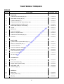
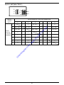
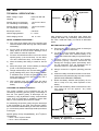
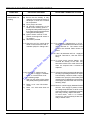
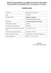
D
ow
nl
oa
de
d
fro
m
w
w
w
.S
co
ot
e
rT
im
e.
USA
ne
t
Service Station Manual
MODEL NO.: 00300728
ne
t
im
e.
NOTICE
d
fro
m
w
w
w
.S
co
ot
e
rT
All information contained in this manual is based on the latest product
information at the time of publication. Bajaj Auto Ltd. accepts no liability for
any inaccuracies or omissions in this publication , although every possible
care has been taken to make it as complete and accurate as possible.
All procedures and specifications subject to change without prior notice.
The right is reserved to make changes at any time without prior notice and
without incurring an obligation to make such changes to product
manufactured previously. Contact your authorised bajaj dealer for the
latest information on product improvements incorporated after this manual
was issued.
D
ow
nl
oa
de
DOC. NO. 36 02 0147
FOREWORD
We have pleasure in presenting this Service Manual for Bajaj LEGEND This manual is designed
by bajaj auto ltd., primarily for use by authorised bajaj dealers and their qualified mechanics.
However, it contains enough details and basic information to make it useful to the vehicle owner
who desires to carry out his own basic maintenance and repair work.
Since a certain basic knowledge of mechanics, the proper use of tools, and workshop procedures
must be understood in order to carry out maintenance and repair satisfactorily; the adjustments,
maintenance, and repairs should be carried out only by qualified mechanic. If proper adjustment can
ne
t
not be obtained by following the procedures in this manual, find out the cause and correct as
necessary.
.S
co
ot
e
rT
im
e.
In order to perform the work efficiently and to avoid costly mistakes, the mechanic should read the
text thoroughly, familiarising himself with the procedures before starting work, and then do the work
carefully in a clean area. Wherever special tool or equipment is specified, make sure that same are
used. Precision measurements can only be made if proper instruments are used and the use of
substitute tools may adversely affect safe operation of the vehicle.
d
fro
m
w
w
w
The safety precaution and special instructions have been printed in bold type to draw your attention.
These instructions indicates points of particular interest for more efficient, convenient and safe
operation. It is essential that you do not neglect these instructions while carrying out repairs so as
to avoid any personnel injury and damage to or destruction of equipments and vehicle.
D
ow
nl
oa
de
As the technique of repair/maintenance procedure develops and as the manufacturing process
changes, it is likely that this Service Station Manual will be subject to modifications as necessary.
The manual is therefore, to be taken valid for operation on the date of its print. For subsequent
modifications and informations always refer to Service Information Circulars.
This manual has been divided into various sections for convenience of presenting the contents in
a useful manner. Please refer to the detailed Index for locating the section/information you want.
WARNING : This manual is intended for use by experienced mechanics, and is not intended
for use by the general public. Therefore, please refer to the appropriate Owner's Manual for
warnings applicable to this scooter. Mechanical repair can be hazardous, and is very
dangerous if you are inexperienced or unknowledgeable. We strongly urge you to never
undertake repair operations with which you are not completely familiar. The repair operations
described in this book must be carried out exactly as described, in order to ensure that the
scooter is returned to safe condition after you have worked on it. Failure to observe this
warning can lead to a dangerous condition which could lead to an upset, accident, serious
injury, or even death.
INDEX
Sr.No.
Description
Page No.
1.
Identification Data
1
2.
Technical Specification
2
3.
General Information
4.
Periodic Maintenance Chart
5
5.
Check and Adjustments during P.D.I. and 1st, 2nd, 3rd, 4th & 5th Servicing
6
7.
Scheduled Maintenance
8.
General Precautions (Dismantling / assembly )
9.
Tightening Torques
.S
co
ot
e
rT
im
e.
ne
t
3-4
7-13
14-15
16-17
Special Tools
11.
Engine Exploded View
12.
Dismantling and Assembly : Engine
13.
Service Data : Engine
14.
Dismantling and Assembly : Chassis
15.
Service Data : Chassis
16.
Electricals
17.
Electrical Wiring Diagram
60-61
18.
Trouble Shooting Guide
62-63
D
ow
nl
oa
de
d
fro
m
w
w
w
10.
18-21
22
23-35
36-37
38-46
47
48-59
IDENTIFICATION DATA
The chassis and engine serial numbers are used to register the vehicles. They are the only means of identifying
your particular vehicle from the other of the same model and type. These serial numbers may be needed by your
dealer when ordering the parts. In the event of theft, the investigating authorities will require both these numbers
in addition to the model, type and any special features of your vehicle that can help identification.
w
w
w
.S
co
ot
e
rT
im
e.
ne
t
Serial numbers with prefix 28 C and 28 E are stamped on chassis and engine of the vehicle in the position indicated
in the figures below :
Chassis number
fro
m
Engine number
Location of VIN Number
D
ow
nl
oa
de
d
The chassis and engine numbers serial numbers are used by the factory to identify your particular vehicle. Always quote
these numbers when ordering parts or when making inquiry with regard to service operations. The vehicle is identified by
the Department of Motor Vehicles in your state by the Vehicle Identification Number. It is a crime in all states to alter any
of these numbers.
VIN Number
VIN Number
1
TECHNICAL SPECIFICATIONS
CONTROLS :
Steering
Accelerator
Clutch
Brakes
Front
:
:
:
:
:
:
12 Volts, DC
12V- 9Ah
35/35 W
5 / 10 W
10 W
12V, DC
.S
co
ot
e
rT
im
e.
ELECTRICALS :
System
Battery
Head lamp
Tail/stop lamp
Side indicator lamp
Horn
ne
t
: Lever operated on right side of
handle bar
: Pedal operated by right foot.
Rear
DIMENSIONS :
Length
Width
Wheel base
Height
Saddle height
: 1825 mm / 71.85"
: 685 mm / 26.97"
: 1275 mm / 50.20"
: 1150 mm / 45.28"
: 805 mm / 31.69"
WEIGHTS :
Curb weight
: 115 kg / 253 lbs
w
m
fro
oa
de
d
CHASSIS AND BODY :
Frame type
: Monocoque construction
Suspension
Front
: Leading link Anti-dive ,variable
rate coil spring & double
acting shock absorber
Rear
: Variable rate coil spring &
double acting shock absorber
Brake type
Front & Rear : Mechanical expanding
shoe friction type.
Brake size
Front
: 150 mm dia / 5.91"
Rear
: 130 mm dia / 5.12"
Tires
Front
: 3.50 X 10, 4 P.R.
Rear
: 3.50 X 10, 4 P.R.
Tire pressure FRONT
: 1.25 kg/cm2 (18 Psi)
REAR (without pillion) : 1.75 kg/cm2 (25 Psi)
REAR (with pillion)
: 2.50 kg/cm2 (36 Psi)
ow
nl
Max.total weight
(including driver)
D
Fuel tank capacity
: Handle bar
: Twist grip type on right hand
of handle bar
: Twist grip type on left hand of
handle bar
: Lever operated on left side of
handle bar
Gears
w
w
ENGINE & TRANSMISSION
Type
: Four stroke, Forced Air cooled.
No. of cylinders
: One.
Bore
: 57.00 mm
Stroke
: 57.00 mm
Engine displacement : 145.45 cc
Maximum net power : 9.00 HP / 6.71 kw at 6000 rpm.
Maximum net torque : 1.15 kgf.m.at 4000 rpm
Compression Pressure : 12 ± 1 kg/cm2
Compression Ratio : 9.3 : 1
Idling speed
: 1200 ± 150 rpm
Ignition system
: C. D. I.
Fuel
: 87 octane petrol.
Carburettor
: Keihin PB 20
Spark Plug
: Champion PL 7 YC
Spark plug gap
: 0.6 to 0.7 mm
Lubrication
: Wet sump, forced lubrication.
Starting
: Kick start / Electric start
Clutch
: Wet, multidisc type.
Transmission
: 4 speed constant mesh.
Overall gear ratios
First gear
: 17.33 : 1
Second gear : 10.81 : 1
Third gear
: 7.96 : 1
Fourth gear
: 6.11 : 1
Primary gear ratio
: 2.75 : 1
PERFORMANCE :
Maximum speed
Climbing ability
: 256 kg / 564 lbs
: 90 km/h / 55 mph
with 68 kg/150 lbs
(single rider) payload
: 25.0 % max.
NOTES :
l All dimensions are under unladen condition.
l Above information is subject to change, for the
latest information please contact Service dept. .
: 1.32 Gal. (5 litres)
2
GENERAL INFORMATION
l Confirm that the turn indicator switch is “OFF” and
supplementary engine stop switch in “RUN” position.
l Press the Start Button to start the engine.
l Release start button as soon as engine starts.
RUNNING IN :
In the process of manufacturing the best possible materials
are used and all machined parts are finished to a very high
degree of accuracy. But it is still necessary to allow the
moving parts to break in before subjecting the engine to
maximum stresses. The future performance and
reliability of the engine depends upon the care and
restraint exercised during its early life. The general
running in rules are :
When engine is cold :
l Pull the choke lever in 'ON' position.
l Press the Start Button with accelerator in completely
closed position.
l Once the engine warms up, release choke lever to
'OFF' position .
l
l
l
l
Always keep to the specified running-in speed.
Do not ride the vehicle at high speed.
Do not race the engine.
Do not run the engine under constant speed for
prolonged period, please vary the speed for better
bedding in of the mating parts.
l Do not start moving or race the engine immediately
after starting. Run the engine for a few minutes at
idle speed to give the oil a chance to workup into all
engine parts.
ne
t
When engine is warm :
l While starting warm engine, open the accelerator 1/8th
to 1/4th and press the Start Button.
.S
co
ot
e
rT
im
e.
NEVER REV UP THE ENGINE TO HIGHER RPMs
IMMEDIATELY AFTER STARTING OR IN NEUTRAL
GEAR. If the engine is raved to higher RPMs immediately after starting it may lead to severe engine
damages as lubricating oil take some time to reach all th
components.
The table given below shows the maximum permissible
speed during running in :
w
Max. vehicle speed in
gears (mph)
Ist
IInd
IIIrd
IVth
10
20
30
40
fro
Don’t run vehicle with clutch lever partially depressed or
don’t slip the clutch to overtake or to climb a gradient.
This will damage the clutch.
oa
de
d
STARTING : (Kick start)
m
0-1200
w
w
Distance
in miles
Moving from ‘Stand still position’
Pull the clutch lever and twist the gear control tube
upwards in one smooth motion to put the vehicle in 1st
gear. Release clutch gradually and simultaneously open
the throttle gradually to move away from stand still
position.
l Turn the Ignition switch to 'ON' position.
l Confirm that the vehicle is in neutral gear, turn indicator switch is “OFF” and supplementary engine stop
switch in “RUN” position.
ow
nl
Downshifting of gears i.e.. Shifting from 4th to 3rd to
2nd to 1st gear :- Reduce the speed of the vehicle.
Depress the clutch lever completely and twist the gear
lever upwards and release the clutch lever gradually and
increase throttle. For further ease of gear shifting slightly
open the throttle momentarily while depressing the clutch
lever and then twist the gear lever upwards.
D
How to operate kick:
Move the kick slowly.
Ensure that ratchet is engaged, then kick.
When engine is cold :
Use ‘CHOKE’ only for cold starting. Do not open throttle.
Pull the choke lever and operate kick for starting.
Release the Choke lever to ‘ OFF’ position immediately
once the engine starts.
Do not tilt the vehicle towards spare wheel side. Engine
oil may drain out from the crankcase breather tube and
hence there will be a drop in oil level in the crankcase.
Accidently if the vehicles falls down on spare wheel side,
ensure correct oil level after lifting and placing the vehicle on stand.
When engine is warm :
Do not open throttle while kick starting. If the engine
fails to start with 2-3 kicks, slightly open the throttle (not
more than 1/4 th turn) before kicking.
Braking :
For stopping the vehicle smoothly and safely first close
the accelerator and then apply front and rear brake
simultaneously. Using only the front or rear brake is
dangerous and cause skidding and loss of control.
Anticipate your stop well in advance for avoiding sudden
braking which may be dangerous.
STARTING : (With Self Start)
l Turn the Ignition switch to 'ON' position.
l Confirm that the vehicle is in neutral gear otherwise
engine will not start.
(Neutral switch is fitted on gear shifter assly for this
purpose as a safety feature.)
3
l Don’t overload the vehicle above the specified pay
load.
Stopping the engine :
l Close the throttle.
l For stopping the engine, turn the key to 'OFF' position
of ignition switch.
l Supplementary engine stop switch on RH control
switch can also be used to stop the engine when
ignition switch is not to be put off.
l Use the accelerator judiciously. Think of the
accelerator barrel as fuel cock. The more you will
turn it, the more petrol will be consumed.
l For better fuel economy,change the gear as given
below :
Change 1st to 2nd gear at 6 mph.
Change 2nd to 3rd gear at 12 mph.
Change 3rd to 4th gear at 18 mph.
Drive at 18 to 30 mph in 4th gear.
Parking :
l Always prefer to park the vehicle on level ground and
on the centre stand.
l Lock the steering-cum-ignition lock.
l Cut off the engine if you want to stop more than for
two minutes. Remember, idling costs fuel.
DAILY SAFETY CHECKS :
Check the following items each day before you ride.
These checks hardly require any time and habitual
performance of these checks will help to ensure a safe,
reliable ride.
If any irregularities are found during these checks refer to
the maintenance chapter or contact an authorised bajaj
dealer for the action required to return your vehicle to a
safe operating condition.
Vehicle condition :
e.
ne
t
l Check all fuel lines and connections whenever your
vehicle smells of petrol. Never fill the petrol right up
to the filler cap.
.S
co
ot
e
rT
im
l Always maintain the recommended tyre pressure
and check it every week. Under-inflated tyres
increases rolling resistance and thus costs both fuel
and tyre life.
Fuel :
l Ensure that the brakes are not dragging/binding.
w
w
Electrical :
fro
m
Operation of switches, lighting of head, tail /brake lamp,
horn sound ,battery electrolyte level and battery condition.
Brakes :
oa
de
d
Front and rear brake effectiveness, lever play.
Tires :
Regular maintenance will save fuel and money
assuring you trouble free, enjoyable and safe riding.
D
ow
nl
Inflation pressure, cracks, cuts and foreign material
embedded in tread.
FUEL SAVING TIPS :
l For keeping the engine healthy :
q Inspect and clean the spark plug, adjust the
gap.
q Clean the air filter.
q Service carburettor and adjust idling speed.
q If there is a power loss, then contact an
authorised bajaj dealer and get the vehicle
properly tuned.
w
Enough fuel for the planned distance of travel & check
leakage if any.
A well maintained vehicle can contribute a lot to the saving
of petrol. Following are a few simple tips for keeping your
vehicle healthy and your pocket wealthy.
Good riding habits :
l Ride smoothly and steadily at an optimum driving
speed of 18 to 25 mph.
l Don’t waste petrol by stop and go riding and by
sudden starts and stops.
l Avoid harsh braking. Do not brake unless it is very
essential, anticipate your stops, turns well in advance
and slow down by deceleration.
l Choose a proper route to ride especially in peak
hours.
4
The maintenance and adjustments outlined in this section are easily carried out and must be done in accordance with
the periodic maintenance chart to keep the vehicle in good running condition. The initial maintenance is vitally important
and must not be neglected.
PERIODIC MAINTENANCE CHART
FREQUENCY
WHICHEVER COMES FIRST
ODOMETER READING
(MILES)
SR.
NO.
OPERATION
EVERY
300
1200 3000
6000
9000
15000
1
Servicing
l
l
l
l
2
Engine oil: Replacement
l
l
l
l EVERY
l 3000 MILES
l
3
Oil strainer cleaning
l
l
l
EVERY 3000 MILES
4
Air filter element cleaning j
5
Spark plug : Cleaning/gap setting **
**
l
3000 MILES
l
l
l
7
Fuel line / Fuel Filter element cleaning
l
9
Control cables adjustment
Tightening nuts/bolts/fasteners
Month
11
Check functioning of all electrical components
Day
12
Head lamp alignments- check & adjust
13
Tire rotation
6000 MILES
14
Tire pressure
Week
15
Steering column : check and adjust
16
Front/rear brake : inspection/adjustment
fro
m
w
w
w
10
l
l
l
l
l
l
l
l
l
l
l
l
l
l
l
l
l
l
l
l
l
l
l
l
l
l
l
l
l
l
l
l
l
l
l
l
l
l
l
l
l
l
l
l
l
l
l
l
l
l
l
l
l
l
l
l
l
l
l
l
l
l
Month
l
l
l
l
l
l
l
Apply petroleum jelly on battery terminals Month
l
l
l
l
l
l
l
o
o
o
o
o
o
o
ow
nl
Check battery electrolyte level
Lubricate
D
18
l
l
l
l
l
d
oa
de
: Overhaul
l
rT
Check & adjust valve clearance **
6000 MILES
.S
co
ot
e
8
ne
t
l
im
Carburettor cleaning /overhaul **
Fuel Filter replacement if required
l
l
l
6000 MILES
6
17
l
e.
: Replace
l
l
12000
a) Front and rear brake levers
b) Control cables , gear shifter
n
n
c) Speedo pinion/gears/cable
o
o
d) Brake cam shafts
After
e) Stand pivot
washing
f) Front fork bearing races/balls
the vehicle
o
g) Wheel bearings
h) Front suspension
o
o
o
o
o
o
o
o
o
o
o
o
o
o
o
o
Refer Page No. 15
l
n
Indicates operation to be performed.
Indicates lubrication by SAE 20W40 of API SC/CC grade oil.
o
j
**
Indicates lubrication by Lithium-calcium soap base grease.
To be cleaned more frequently in dusty area.
Must be performed to maintain emissions warranty.
5
CHECK & ADJUSTMENTS TO BE CARRIED OUT DURING
P.D.I., 1st, 2nd, 3rd , 4th & 5th SERVICING
Sr. No.
Operation to be carried out
P.D.I.
1st
2nd
3rd.
4th
5th
l
l
l
l
l
l
l
l
l
l
Check all nuts and bolts for
tightness especially handle bar bolt,
engine foundation bolt, shock absorber
nuts and wheel nuts etc.
l
l
l
l
l
l
4
Check Engine oil level and top
up, if necessary.
l
5
Flush and refill Engine oil
l
6
Remove and clean air cleaner filter element
7
Clean spark plug , adjust the gap and refit
8
Clean the carburettor / adjust idling speed
9
Check & adjust valve clearance
e.
l
l
l
l
l
l
l
l
l
l
l
l
l
l
l
l
l
im
3
rT
Check and correct tyre inflation pressure
including that of spare wheel
.S
co
ot
e
2
w
w
w
Wash and clean the vehicle on receipt
ne
t
l
1
Carry out lubrication as per lubrication chart
11
Check steering-cum-ignition lock & other lock
for proper operation.
l
12
Check for smooth operation of choke lever
and accelerator.
l
13
Check front & rear brakes for efficient working.
l
14
Check and adjust steering.
l
15
Check all lights, horn, switches, speedometer
for satisfactory working.
l
16
Initial charging of battery. Install & apply
Petroleum Jelly on Terminals.
l
17
Check battery electrolyte level & apply
petroleum jelly on terminals
18
Test drive the vehicle.
l
19
Repair for any other defects seen or
observed during test drive
l
20
Clean the vehicle before delivery.
l
l
l
l
l
l
l
l
l
l
l
l
l
l
l
D
ow
nl
oa
de
d
fro
m
10
l
6
l
l
l
l
l
l
l
l
l
l
l
l
l
l
l
l
l
l
l
l
l
SCHEDULED MAINTENANCE
l Fit back the dipstick and tighten it securely.
l Ensure that there is no oil leakage.
CLEANING
The vehicle must be cleaned periodically by using
pressurised water. Before cleaning the vehicle cover the
important parts like ignition switch, silencer, ignition unit,
H.T. coil,starter motor by plastic bags. Don’t apply the jet
of water directly towards electrical parts such as switches,
ignition unit, coils etc. otherwise they may get damaged.
C
B
Brushing with parafin and wiping dry with clean rag is
advisable for external cleaning of the engine. All painted
surfaces should be washed with water. Do not use
kerosene or detergent soap on painted surfaces as it
damages the paint and turns it dull.
A
If necessary, blow with compressed dry air, the head lamp
reflector, clean or wipe off dust with a very soft feather
brush. After washing, dry the vehicle and carry out the
lubrication.
Oil replacement:
If the oil is used for a longer duration its lubricating
performance deteriorates. So it is necessary to replace
the oil in accordance with periodic maintenance chart.
For replacing the oil follow the procedure given below :
l Run the vehicle for few minutes.
l Place the vehicle on main stand. Let the oil settle.
l Remove the oil drain bolt with its aluminium washer.
Also take out dip stick. Let the oil drain completely.
Tighten the drain bolt with new aluminium washer
securely. (Tightening torque 2.6 - 3.0 kg.m.)
l By using a funnel pour the recommended oil from the
oil filler opening hole or open Inlet tappet cover & pour
oil.
l Fit back the dip stick and tighten it securely.
l Ensure that there is no oil leakage.
fro
m
w
w
w
.S
co
ot
e
rT
im
e.
WARNING: Washing your scooter will allow the brakes to
become wet, with the same effect as riding on a wet road.
Whenever the brakes become wet, always dry them by
gently applying the brakes, repeatedly, until the heat
causes the brakes to dry and full brake function is
restored. Failure to follow this procedure can lead to loss
of brake effectiveness and a serious accident.
PERIODIC MAINTENANCE
Periodic maintenance (in accordance with the periodic
maintenance chart) of a vehicle is most important to
prolong its life , trouble free running and ensure your safety
while driving.
B) Oil level gauge
D) Lower level
ne
t
A) Oil filler hole
C) Upper level
D
d
LUBRICATION
To reduce the friction between two moving parts lubricate
them periodically. Insufficient lubrication will cause rapid
wear, damaging the parts prematurely. Lubricate everytime
after washing the vehicle and whenever the vehicle is
operated under wet, rainy conditions. Before lubricating,
clean off any rusty parts and wipe off old grease, oil or dirt.
ow
nl
oa
de
Do not use inferior grade of oil as a replacement for
the recommended oil, otherwise it will lead towards
engine troubles.
Oil capacity: 1100 ml (For newly assembled engine)
: 1000 ml (For drain & refill)
Recommended oil : SAE 20 W40 of API SC/SF grade
D
A few drops of oil are effective to keep bolts and nuts away
from rusting and sticking. This makes removal easier.
Please refer lubrication chart, for details of lubrication.
Replace oil after every 5000 kms / 3000 miles.
ENGINE OIL : Check engine oil level daily.
For proper functioning of cylinder block / piston , crankshaft,
tappets, clutch and transmission, the oil should be
maintained at an appropriate level.
Oil level inspection :
l Place the vehicle on centre stand, on a level ground.
l Clean the surface area around the oil filler opening.
l Unscrew the dipstick from oil filler opening hole and
wipe it dry.
l Put the dip stick, on oil filler opening , take out the dip
stick and observe the oil level on it.
l There are two marks engraved on it. If the level is
below the lower level mark, top up with the
appropriate quantity of recommended oil up to upper
level mark. If the oil level is too high i.e. above
the upper level mark, drain some oil from drain hole.
Drain bolt
7
SPARK PLUG
AIR FILTER :
The condition of the spark plug indicates how the engine
is operating. A defective spark plug will lead to difficult
starting and poor performance. Engine heat and
combustion chamber deposits will cause any spark plug
to slowly break down and erode over a period of use. The
spark plug should be removed periodically and inspected
for electrode gap and the colour at the tips, at regular
intervals as specified in periodic maintenance chart.
Bigger PU foam air filter is provided for better breathing.
If the air filter is clogged, intake air flow will be restricted
which results in low engine power ,increase in fuel
consumption & spark plug fouling.
Air filter removal :
l Open seat lock & lift the seat. Remove LH bonnet.
l Remove spare wheel.
l Pull 'Cover air filter slot' from slot provided on chassis
for inserting air filter assly.
l Take out air filter assly carefully from slot.
l Remove air filter element.
If the engine is operating correctly and the machine is
being ridden properly, the colour at the electrode tip will
be greyish yellow to light brown. The centre electrode
will not have pitting and the side electrode will have
constant thickness. The combustion chamber residues
left on the tip gives an indication of engine performance
as follows :
e.
im
rT
.S
co
ot
e
w
Removal of air filter
w
w
Clean the spark plug preferably in a sand blasting device
and thoroughly clean off abrasive material left on it .
ne
t
l Greyish yellow to light brown : Correct running
of engine. Spark plug is perfectly matched for
optimum engine performance.
l Shining black or wet carbon deposits : Presence
of oil in fuel.
l Burnt white/pearly deposits of metallic enamel
beads: Overheated engine, too lean air fuel mixture,
spark plug not fully tight, use of hotter plug.
l Dull black velvety carbon deposits : Too rich fuel
air mixture, electrode gap too wide, plug too cold,
clogged air cleaner, insufficient high tension voltage,
continuous slow speed driving.
d
fro
m
Measure the gap between the electrodes with the wire
type thickness gauge, adjust the gap if incorrect by
bending the outer electrode carefully. The gap at the
electrode for optimum performance is 0.6 to 0.7 mm.
ow
nl
oa
de
Connect the H.T. lead to spark plug, ground the plug and
check the current jumping across the plug electrode.
The bright blue spark should jump across the electrodes.
Replace the spark plug in case of following conditions:
D
1. Excessive electrode wear
3. Chipped off insulator
2. Cracked insulator.
4. Shorted plug.
Air filter cleaning :
l Soak the element for about 1/2 minute in high flash
point stoddard solvent or equivalent.
l Squeeze the element, blow the air so that it dries.
l Dip the element in 20 W 40 oil. Soak the element for
about 1/2 minute.
l Squeeze the element hard, manually so that excess
oil is removed.
l Assemble the air filter assly. insert it inside slot.
l Fix the 'Cover air filter slot' on chassis.
DO NOT USE PETROL OR LOW FLASH POINT SOLVENT
FOR CLEANING. THIS MAY CAUSE BACK FIRE.
While installing back the spark plug, check for ;
1. The condition of sealing washer.
2. Cleanliness of contact surfaces of spark plug seat
and cylinder head seat.
Air filter element should be cleaned as per periodic
maintenance chart. If vehicle is operating in dusty roads
/ area the element should be checked and cleaned more
frequently.
When installing the plug, first screw it in with finger
and then use the spanner for the final tightening
only. This will prevent chances of stripping of the
cylinder head threads.
Recommended Spark Plugs :
Champion PL 7 YC
Spark Plug Cap : Resistance
Electrode gap : 0.6 to 0.7 mm
Wash
Spark Plug gap
8
Squeeze Out
And Dry
Oil
Squeeze Out
Excess oil
l Open and close the throttle a few times to make sure
that the idling speed does not change. Readjust if
necessary.
l With the engine idling, turn the handle bar to either
side. If the handle bar movement changes the idling
speed, the accelerator cable may be improperly
adjusted, damaged or improperly routed. Rectify
any of these conditions before riding.
l Do not attempt to compensate for faults in other
systems by adjusting the idle speed.
ACCELERATOR GRIP
The accelerator grip controls the movement of carburettor
throttle valve and ignition timing (For TRICS). If the
accelerator grip has excessive play due to cable stretch,
it will cause a delay in carburettor response especially at
low engine rpm and cause improper ignition timing. Also
throttle valve will not open completely in full throttle
condition. On the other hand, if the accelerator grip has no
play, control of carburettor throttle valve will be difficult. If
the inner cable is overstretched, idling rpm will be too high
and cause improper ignition timing.
Normal idling speed : 1200 ± 150 rpm
ACCELERATOR PLAY ADJUSTMENT :
im
e.
ne
t
l Check the accelerator play by lightly turning the grip
back and forth.
l Accelerator play can be adjusted by cable
adjuster (a) provided on carburettor. Loosen the
adjuster lock nut and turn the adjuster until specified
free play is obtained. Retighten lock nut after
adjustment is over.
A
.S
co
ot
e
rT
ACCELERATOR GRIP PLAY : 4 - 5 MM.
A. Idling adjustment screw
C. Increase speed
fro
m
w
w
w
A
B
D
B. Decrease speed
D. Air screw
REMOVAL OF WHEELS
For removal of wheels in case of puncture or Tire rotation,
follow the procedure given below :
d
Front wheel :
oa
de
l Rotate wheel cover cap in anticlockwise direction
and take out.
l Pull wheel cover.
l Remove 5 nuts (3 special & 2 regular) and take out
front wheel assly.
l After mounting wheel, check the sequence of 5
mounting nuts.
ow
nl
Adjusters (A) on Carburettor.
C
D
CAUTION : Always maintain correct accelerator play.
It is very important for vehicles fitted with 'TRICS' as
the ignition timing is regulated by throttle opening.
IDLING SPEED ADJUSTMENT
Whenever the idling adjustment is disturbed follow the
procedure given below for setting proper engine idling.
l Open seat lock & lift the seat. Remove engine.
l Start engine & drive it for atleast 5 kms.or warm the
engine till the oil temp. reaches 800 C.
l Then set the engine idling r.p.m. by rotating the idle
adjustment screw clockwise or anticlockwise with
the help of a screw driver.
l For the precise adjustment of idling speed, use of
tachometer is recommended.
Front wheel nuts
9
brakes which can lead to loss of control, an upset, or a
serious accident with subsequent serious injury or even
death.
Rear wheel :
l Remove LH cover.
l Remove spare wheel
l Rotate wheel cover cap in anticlockwise direction
and take out.
l Pull wheel cover.
l Tilt the vehicle on engine side.
l Remove 5 nuts (3 special & 2 regular) and take out
front wheel assly.
l After mounting wheel, check the sequence of 5
mounting nuts.
3 to 5 mm
ne
t
an
ti d
ive
Front Brake Lever Play
im
e.
Front brake adjuster
Inspection window
fro
m
w
w
Installation :
l Install the rear wheel on brake drum studs.
l Install the plain and spring washers.
l Install the nuts and tighten them securely (Tightening
torque - 2 to 2.5 kg.m.)
l The adjusting nut for rear brake is located on rear
brake inner cable at the end.
l Depending upon the adjustment required, turn the
adjuster back or forth as follows :
Turning the adjusting nut in (clockwise direction)
increases the play at the brake pedal.
Turning the adjusting nut out (anticlockwise direction)
reduces the play at the brake pedal.
l After adjustment, check the wheel for free rotation
and for braking effectiveness.
l Rear brake shoe, liner wear can be checked through
the inspection window on rear brake drum, after
unscrewing the plug.
w
Rear wheel nuts
.S
co
ot
e
rT
REAR BRAKE ADJUSTMENT
Check the rear brake pedal play as shown in figure. If it
is more or less than the standard, adjust the rear brake.
ow
nl
oa
de
d
BRAKES
Brakes should always be maintained in perfect condition
for safety. Brake drum wear, brake lining wear and brake
cable stretch causes the brakes to go out of adjustment.
This increases the free play at the brake lever and reduces
the braking efficiency.
"If the brake remain ineffective despite above
adjustments, check brake shoes , brake drum & brake
cable."
D
FRONT BRAKE ADJUSTMENT
Check the front brake lever play. If it is more or less than
the standard, adjust the front brake.
l The adjusting nut for front brake is located on front
brake inner cable at the end.
l Depending upon the adjustment required, turn the
adjuster back or forth as follows :
Turning the adjusting nut in (clockwise direction)
increases the play at the brake lever.
Turning the adjusting nut out (anticlockwise direction)
reduces the play at the brake lever.
l After adjustment, check the wheel for free rotation
and for braking effectiveness.
Rear Brake pedal Play
"If the brake remain ineffective despite above
adjustments, check brake shoes , brake drum & brake
cable."
WARNING: Never permit the operation of a scooter with
a brake cable in anything but absolutely perfect condition.
Any wearing or fraying of the cable can lead to ineffective
Rear brake adjusting nut
10
10 to 15 mm
TIRES
When exchanging the bulbs, always replace the bulbs
with that of the specified type and rating. This is important
to prevent the electrical lighting circuit from malfunctioning.
For better road-holding and longer tire life always maintain
correct air pressure. Overinflation will cause bumpy ride
and faster wear of the tire at the centre. Under-inflation will
cause poor steering and faster wear at the sides.
Head light bulb replacement :
For replacing head light bulb follow the procedure given
below :
Recommended Tire Pressure
Rear
l Remove 2 screws on Handle bar rear cover holding
Handle bar front cover.
1.25 Kg/cm2 (18 PSI)
Front
Solo
1.75 Kg/cm2 (25 PSI)
With Pillion 2.50 Kg/cm2 (36 PSI)
Tire wear/damage :
Worn out tire is unsafe. Replace the tyre when the tread
depth reaches to less than 3 mm.
FLASH
ne
t
Tire tread depth :
Service limit
5 to 6 mm
3 mm
im
rT
.S
co
ot
e
Standard
e.
Measure the tire tread depth by using the depth gauge. If
tread pattern is not visible, replace the tire. Also replace
the tire when the tire tread depth is found to be less than
the service limit.
Handle bar cover (Rear) mounting screws.
w
w
w
Tire rotation :
l Remove one screw provided on H. Bar front cover
just below H. Light adjustment screw.
l Carefully disengage the locking lugs of handle bar
front cover by prying with the help of a small screw
driver.
l Disconnect Head Lamp harness coupler . Take out
Handle bar front cover with head lamp assly.
l Slide bellow from head lamp bulb holder.
fro
m
To even out tread wear it is necessary to change the face
of tire and to rotate it position wise every 10000 kms.
oa
de
d
Change the face of the tire in relation with the wheel rim
and inflate tire to the specified pressure. The good tire
should be kept at the rear, which is a driving wheel.
CONTROL CABLES :
D
ow
nl
Due to continuous operation of cables by the brake levers
and throttle the inner cables are subjected to wear and
tear. Cable maintenance is primarily concerned with
preventing deterioration due to rust and weather as well as
providing proper lubrication for free movement of inner
cables in the outer casing. For checking any of the control
cables follow the procedure given below :
l Disconnect the inner cable.
l Check free movement of the cable within its casing.
If movement is obstructed, check for fraying or
kinking of cable strands. If such damage is noticed,
replace the inner cable or cable assembly as
necessary.
l To lubricate cable, hold it in vertical position. Apply
necessary oil to uppermost end of cable and move
the inner cable to and fro. Leave it in vertical position
until the oil flows down to the lower end. Allow excess
oil to drain and reinstall the cable.
Head light bulb holder
l Remove bulb holder & replace bulb.
Note : Friction free cables do not require lubrication.
BULB REPLACEMENT :
11
Brake/Tail light, rear blinkers bulb replacement :
V
V
For replacing Tail/stop bulb or rear blinkers bulb, remove
2 screws for lens, take out lens & replace bulb.
15°
HV
H
5CM
1M/3.28 FT
HV
2M/6.56 FT
2M/6.56 FT
Hi Beam pattern
Low Beam pattern
Removal of screws for lens
ne
t
Front blinker bulb replacement :
.S
co
ot
e
rT
im
e.
l Remove 2 mounting screws for nose grill and take out
nose grill.
l Remove 2 mounting screws for blinker and take out
blinker assly.
l Take out holder & replace the bulb.
Screw for head lamp adjustment
HEAD LIGHT BEAM ALIGNMENT
STEERING :
w
Steering play :
m
w
w
The headlight beam can be adjusted vertically and
horizontally. If adjusted too low, neither low nor high beam
will illuminate the road adequately. If adjusted too high,
the high beam will fail to illuminate the road.
oa
de
d
fro
l Keep the vehicle off the stand facing a wall.
l Inflate both front and rear tyres to specified inflation
pressure.
l There should be sufficient darkness.
l Keep the vehicle at a distance of 5 meter/16.4 ft from
a wall as shown in figure.
l Raise the front wheel off the ground.
l From the straight forward position of the handle bar
slowly push the handlebar to either side.
l If the handle bar to turn by the action of gravity and
continues moving until its stopper on L.H.and R.H.
side, the steering is not too tight.
l If the handle bar does not begin to turn by the action
of gravity, the steering is too tight necessitating
adjustment.
l Squat in front of the vehicle and grasp the lower ends
of the front fork. Push and pull the fork end back and
forth.
l If the play is felt the steering is loose, necessitating
adjustment.
D
1M/3.28 FT
HV
Inspection :
ow
nl
SCREEN
5 M/16.4 FT
If the steering is too tight, it will be difficult to turn the
handlebar quickly, the vehicle may pull to one side and the
steering stem bearings may become damaged. If the
steering is too loose, the handlebar will vibrate and the
vehicle will be unstable and difficult to steer in a straight
line.
VEHICLE OFF THE STAND
l Start the vehicle. Switch ON the Headlight high beam
and then lower beam.
l Check the beam pattern on the wall.
l For correct pattern of High beam & low beam, a screw
is provided below Head lamp assly. Loose this screw
before carrying out adjustment. Pressing Head light
assly at the top shifts the pattern up and pressing
Head light assly at the bottom, shifts the pattern down.
l The High beam pattern should be as shown in figure
and it should be 1 meter/3.28 ft. above the ground.
l The Low beam pattern should be set 5 cm below the
HV point as shown in the figure.
Adjustment :
l
l
l
l
12
Remove handle bar covers.
Loosen Handle bar bolt & lift up slightly.
Loosen the upper lock ring nut.
If the steering is too tight, loosen the lock nut a
fraction of turn; if the steering is too loose, tighten the
locknut a fraction of turn.
l Tighten the upper lock ring nut to a specified torque.
l Check the steering again. If the steering is still tight
or loose repeat the adjustment. If the proper condition
cannot be obtained inspite of correct adjustment,
inspect the steering parts.
l Install handle bar covers.
LUBRICATION OF FRONT SUSPENSION
The locations of Grease nipples and recommended
intervals for lubrication of Front suspension by grease (HP
multipurpose or equivalent) are as under.
Antidive link bushes & 'O' rings.
OIL STRAINER CLEANING
Lubricate at Every 2000 miles.
l Oil strainer is situated in side the bolt as shown in fig.
l Remove the bolt and take out oil strainer.
l Clean it with petrol. Apply air jet to dry oil strainer and
assembled back.
l Oil strainer should be cleaned in accordance with
periodic maintenance chart ( i.e. at every 3000
miles.)
Needle roller bearings of Front
brake panel.
ne
t
Lubricate at Every 4000 miles.
Lubricate at Every 2000 miles.
.S
co
ot
e
rT
im
e.
Bushes & 'O' rings of Antidive
link & hub pin.
w
NON-USE MAINTENANCE
w
w
Oil strainer bolt
m
BATTERY MAINTENANCE
oa
de
d
fro
l For checking / topping up electrolyte level :
- Remove LH bonnet.
- Remove rubber strap holding battery and slide out
battery slightly for easy topping up.
l Remove battery filler cap & fill distilled water until
the electrolyte level in each cell reaches the upper
level line.
Non-use maintenance is necessary if a vehicle remains
off road for a longer duration. The correct and careful nonuse maintenance carried out before storing the vehicle will
prevent the vehicle from rusting and from such other nonoperational damages like fire hazards.
ow
nl
l Clean the entire vehicle thoroughly.
l Empty the fuel from the fuel tank and carburettor float
bowl (if fuel is left in for a longer time, the fuel will
break and could clog the carburettor.)
l Remove the spark plug and put several drops of 2T
oil into the cylinder. Kick the engine over slowly a few
times to coat the cylinder wall with oil and install back
the spark plug.
l Set the vehicle on a box or a stand so that both the
wheels are raised off the ground.
l Spray oil on all unpainted metal surfaces to prevent
rusting. Avoid getting oil on rubber parts or brake
shoes.
l Lubricate the control cables.
l Cover the entire vehicle neatly. Make sure that the
storage area is well ventilated and free from any
source of flames or spark.
l Remove battery from vehicle.
l Maintain electrolyte level at 'Upper Level'.
l Ensure that battery is fully charged. Charge the
battery once in a month.
l Keep the battery away from rain, dew, moisture &
direct sunlight. Store battery in cool & dry place.
D
CAUTION : Add only distilled water to the battery. Do
not use ordinary water for topping up , it will shorten
life of battery.
l Apply petroleum jelly to the terminals & assembled
back battery on the vehicle .
Location of battery
13
GENERAL PRECAUTIONS (Dismantling / assembly)
Before Servicing
Before starting to service a vehicle, careful reading of the
applicable section is recommended to eliminate
unnecessary work. Photographs, diagrams, notes,
cautions, warnings, and detailed descriptions have been
included wherever necessary. Nevertheless, even a
detailed account has limitations, a certain amount of
basic knowledge is also required for successful work.
(6)
High Flash-point Solvent
A high flash-point solvent is recommended to
reduce fire danger. Always follow manufacturer
and container directions regarding the use of any
solvent.
(7 )
Gasket, O-ring
Do not reuse a gasket or O-ring once it has been
in service. The mating surfaces around the gasket
should be free of foreign matter and perfectly
smooth to avoid oil or compression leaks.
Especially note the following:
ne
t
e.
im
rT
(9 ) Ball Bearing
When installing a ball bearing, the bearing race
which is affected by friction should be pushed by
a suitable driver. This prevents severe stress on
the balls and races, and prevents races and balls
from being dented. Press a ball bearing until it
stops at the stop in the hole or on the shaft.
.S
co
ot
e
Tightening Sequence
Generally, when installing a part with several
bolts, nuts, or screws, they should all be started in
their holes and tightened to a snug fit. Then
tighten them evenly in a cross pattern. This is to
avoid distortion of the part and/or causing gas or
oil leakage. Conversely when loosening the bolts,
nuts, or screws, first loosen all of them by about a
quarter of turn and then remove them.
(8 ) Press
A part installed using a press or driver, such as a
wheel bearing, should first be coated with oil on its
outer or inner circumference so that it will go into
place smoothly.
m
w
w
(2 )
Dirt
Before removal and disassembly, clean the
vehicle. Any dirt entering the engine or other parts
will work as an abrasive and shorten the life of the
vehicle. For the same reason, before installing a
new part, clean off any dust or metal filings.
w
(1 )
d
fro
Where there is a tightening sequence indication in
this Service Manual, the bolts, nuts, or screws
must be tightened in the order and method
indicated.
oa
de
Torque
The torque values given in this Service Manual
should always be adhered to. Either too little or too
much torque may lead to serious damage. Use a
good quality, reliable torque wrench.
D
(4 )
(5 )
Oil Seal and Grease Seal
Replace any oil or grease seals that were removed
with new ones, as removal generally damages
seals.
When pressing in a seal which has manufacturer’s
marks, press it in with the marks facing out. Seals
should be pressed into place using a suitable
driver, which contacts evenly with the side of seal,
until the face of the seal is even with the end of the
hole.
ow
nl
(3 )
(l0 )
(11 ) Seal Guide
A seal guide is required for certain oil or grease
seals during installation to avoid damage to the
seal lips. Before a shaft passes through a seal,
apply a little oil, preferably high temperature grease
on the lips to reduce rubber to metal friction.
Force
Common sense should dictate how much force is
necessary in assembly and disassembly. If a part
seems especially difficult to remove or install, stop
and examine what may be causing the problem.
Whenever tapping is necessary, tap lightly using
a wooden or plastic faced mallet. Use an impact
driver for screws (particularly for the removal of
screws held by a locking agent) in order to avoid
damaging the screw heads.
(12 ) Circlip, Retaining Ring
Replace any circlips and retaining rings that were
removed with new ones, as removal weakens and
deforms them. When installing circlips and
retaining rings, take care to compress or expand
them only enough to install them and no more.
Edges
Watch for sharp edges, especially during major
engine disassembly and assembly. Protect your
hands with gloves or a piece of thick cloth when
lifting the engine or turning it over.
(13 ) Cotter Pin
Replace any cotter pins that were removed with
new ones, as removal deforms and breaks them.
14
(16 ) Replacement Parts
When there is a replacement instruction, replace
these parts with new ones every time they are
removed. These replacement parts will be
damaged or lost their original function once
removed.
(14 ) Lubrication
Engine wear is generally at its maximum while the
engine is warming up and before all the rubbing
surfaces have an adequate lubricative film. During
assembly, oil or grease (whichever is more
suitable) should be applied to any rubbing surface
which has lost its lubricative film. Old grease and
dirty oil should be cleaned off. Deteriorated grease
has lost its lubricative quality and may contain
abrasive foreign particles.
(17 ) Inspection
When parts have been disassembled, visually
inspect these parts for the following conditions or
other damage If there is any doubt as to the
condition of them, replace them with new ones.
e.
im
rT
w
.S
co
ot
e
“Standards” : Show dimensions or performances
which brand-new parts or systems have.
m
fro
Wire strands
Yellow/red
D
Yellow
Red
d
ow
nl
Red
Name of Wire Color
oa
de
Wire (cross-section)
Crack
Warp
Dent
Wear
Deterioration
(18 ) Service Data
Numbers of service data in this text have following
meanings:
w
w
(15 ) Electrical Wires
All the electrical wires are either single-colour or
two-colour and, with only a few exceptions, must
be connected to wires of the same colour. On any
of the two-colour wires there is a greater amount
of one colour and a lesser amount of a second
colour, so a two-colour wire is identified by first the
primary colour and then the secondary colour. For
example, a yellow wire with thin red stripes is
referred to as a “yellow/red” wire; it would be a
‘’red/yellow” wire if the colours were reversed to
make red the main colour.
Abrasion
Hardening
Bent
Scratch
Colour change
Seizure
ne
t
Don’t use just any oil or grease. Some oils and
greases in particular should be used only in certain
applications and may be harmful if used in an
application for which they are not intended. This
manual makes reference to molybdenum disulfide
grease (MoS2 ) in the assembly of certain engine
and chassis parts. Always check manufacturer
recommendations before using such special
lubricants.
15
“Service limits”: Indicate the usable limits. If the
measurement shows excessive wear or
deteriorated performance, replace the damaged
parts.
TIGHTENING TORQUES
ENGINE
SR. NO.
PART NAME
TORQUE - Kgm.
NUTS FOR :
Crankcase to Crankcase (Qty. 5)................................................................................... 1.5 to 1.8
2
Gear shifter housing (Qty. 2) .......................................................................................... 1.3 to 1.5
3
Cylinder Head (Qty. 4) ................................................................................................... 2.0 to 2.2
4
Crankshaft clutch side (Gear primary spur) ................................................................... 9.0 to 9.5
5
Crankshaft magneto side (Rotor nut) ............................................................................. 5.5 to 6.0
6
Intermediate shaft (For clutch assly) .............................................................................. 9.0 to 9.5
7
Tappet ............................................................................................................................ 0.8 to 1.0
8
Main shaft ....................................................................................................................... 5.0 to 5.5
9
Cover to Crankcase ....................................................................................................... 1.3 to 1.5
10
Silencer to Cylinder head ............................................................................................... 2.0 to 2.5
11
Crankcase to Crankcase (Qty. 2)................................................................................... 1.3 to 1.5
12
Kick lever ........................................................................................................................ 2.0 to 2.5
.S
co
ot
e
rT
im
e.
ne
t
1
w
w
w
BOLTS FOR :
Cylinder head to Cylinder Block (Qty. 2) ........................................................................ 0.9 to 1.1
14
Silencer to Crankcase (Qty.1) ........................................................................................ 3.0 to 3.5
15
Cam shaft sprocket ........................................................................................................ 1.1 to 1.3
16
Cam chain tensioner adjuster ........................................................................................ 0.8 to 1.0
17
Manifold to Cylinder head .............................................................................................. 0.6 to 0.8
18
Chain tensioner body ..................................................................................................... 0.6 to 0.8
19
Cover to Crankcase ....................................................................................................... 1.3 to 1.5
20
Oil drain bolt ................................................................................................................... 2.6 to 3.0
D
ow
nl
oa
de
d
fro
m
13
SCREWS FOR :
21
Stator plate ..................................................................................................................... 0.6 to 0.8
22
Screw for oil tube assly .................................................................................................. 0.3 to 0.4
23
Stopper plate (Cylinder head) ........................................................................................ 0.6 to 0.8
24
Gear shifter cover ........................................................................................................... 0.6 to 0.8
25
Guide kick (Qty. 2) ......................................................................................................... 0.6 to 0.8
GENERAL :
26
Spark plug ...................................................................................................................... 2.5 to 3.0
27
Cap (Cylinder head) ....................................................................................................... 0.8 to 1.0
28
Oil plug ........................................................................................................................... 2.6 to 3.0
16
TIGHTENING TORQUES
CHASSIS
SR. NO.
PART NAME
TORQUE - Kgm.
NUTS FOR :
Front shock absorber ..................................................................................................... 3.0 to 3.5
2
Fuel cock assly on Fuel tank .......................................................................................... 3.0
3
Engine link mounting on chassis.................................................................................... 3.0 to 4.0
4
Engine mounting on link ................................................................................................. 3.5 to 4.0
5
Pivot securing wheel hub ............................................................................................... 5.0 to 5.5
6
Wheel assly on brake drum (Qty. 5) .............................................................................. 2.0 to 2.7
ne
t
1
im
e.
BOLTS FOR :
Handle bar mounting ...................................................................................................... 3.2 to 3.8
8
Rear shock absorber to engine ...................................................................................... 2.0 to 2.3
9
Front mudguard ............................................................................................................. 0.25 to 0.3
10
Stand .............................................................................................................................. 0.4 to 0.5
w
w
w
.S
co
ot
e
rT
7
STEERING :
Upper bearing race ........................................................................................................ 0.6 to 0.7
12
Ring nut .......................................................................................................................... 5.0 to 6.0
D
ow
nl
oa
de
d
fro
m
11
17
SPECIAL TOOLS
The special tools recommended for carrying out repairs / overhauls are illustrated below. These tools are designed to
facilitate quick and safe repairs. Use of these special tools is recommended to carry out repairs efficiently and for
avoiding costly mistakes such as damages to parts, injuries etc. The following list contains for each tool the description,
tool application and an illustrative sketch.
37-0030-01 : Engine support stand
4. 37-1014-10 : Extractor for input shaft bearing.
ne
t
1.
To be used for removing input shaft bearing from
crankcase clutch side.
2. 37-1003-02 : Extracter
5. 37-1014-13 : Inner driver
fro
m
w
w
w
.S
co
ot
e
rT
im
e.
For supporting engine, crankcase while assembly /
dismantling.
To be used with holder and outer bearing driver for
installing front brake drum bearing.
3. 37-1005-04 : Bearing Driver
6. 37-1014-14 : Inner driver
D
ow
nl
oa
de
d
Extractor for needle bearing in crankcase magneto
side.
Driver for fitting needle bearing in crankcase magneto
side.
To be used with holder & outer bearing driver for
installing input shaft bearing in crankcase (clutch side)
& needle bearings in front brake drum.
18
7. 37-1028-32 : Spur gear holder
11. 37-1030-61 : Bearing driver set
Tool for holding primary gear while removing nut.
Inner Driver f 20 - used with Bearing Driver set for
installing main shaft bearing & magneto side oil seal.
8. 37-1030-34 : Rotor puller
Inner Driver f 25 - used with Bearing Driver set for
installing main shaft oil seal
.S
co
ot
e
rT
im
e.
ne
t
12. 37-1031-07 & 37-1031-08 : Valve spring
compressor assembly with adopter.
w
For pulling magneto rotor from crankshaft.
fro
m
w
w
9. 37-1030-48 : Bearing puller
Used for taking out inlet & exhaust valves by
compressing valve spring in cylinder head.
D
ow
nl
oa
de
d
13. 37-1031-52 : Clutch holder.
Bearing puller for extracting bearing from input shaft.
10. 37-1030-54 : Magneto rotor holder
Used for hold the clutch housing stationary while
loosening & tightening the clutch hub nut.
For holding the magneto rotor stationary while
loosening or tightening the rotor nut.
19
14. 37-1031-53 : Valve adjusting screw driver
18. 37-1801-06 : Bearing races assembly tool
Used for holding screw while adjusting valve clearance.
To be used for installing the upper and lower bearing
race on chassis tube.
15. 37-1519-03 : Bearing driver
.S
co
ot
e
rT
im
e.
ne
t
19. 37-1805-08 : Bearing driver for fork assembly
To be used with bearing driver set (37-1030-61) for
assembling needle roller bearing in front brake drum.
w
To be used for fitting lower bearing race on front fork
tube.
20. 37-1819-03 : Bearing driver
D
ow
nl
oa
de
d
fro
m
w
w
16. 37-1519-04 : Driver
For assembling speedometer gear & spacer in front
wheel brake drum.
Tool for assembling needle roller bearings in steering
column.( To be used alongwith 37-1014-14)
17. 37-1519-05 : Adopter
21. 37-1819-04 : Bearing extracter
For removing speedometer gear & spacer from front
wheel brake drum.( To be used with 37-1001-14)
Tool for removing needle roller bearings from steering
column.
20
22. 37-10BA-56 : Bearing extractor
To remove main shaft ball bearing from crankcase cover.
23. 37-1030-79 : Crankshaft alignment fixture
ne
t
To be used for mounting crankshaft while checking its
run out.
24. 67-7505-51 : Compression Tester
rT
im
e.
To be used for checking compression pressure in the
cylinder.
.S
co
ot
e
25. 37-1030-63 : Hand tester
For checking electrical components. Refer Electrical
Maintenance.
D
ow
nl
oa
de
d
28. 67-1691-69 : Hydrometer
For checking specific gravity of electrolyte.
fro
m
27. 37-2031-02 : Battery charger ( 12T6 - 12V)
For charging battery.
w
w
To be used for tightening fasteners to specified torque.
w
26. 69-7505-26 & 69-7505-28 : Torque wrenches
21
22
ad
ed
nl
o
ow
D
m
fro
e.
ne
t
Ti
m
er
ot
w
.S
co
w
w
ENGINE DISMANTLING
l Take out the engine carefully from the chassis.
l Take out rear wheel and mount the engine on
support stand P.No. 37 1030 01.
REMOVAL OF ENGINE FROM VEHICLE :
l Remove both LH and RH bonnets.
l Drain Engine oil completely by removing drain plug.
A
B
C
C
D
A
e.
ne
t
B
A) Throttle cable
C) Screw for Duct
Ti
m
A) Drain Plug
B) Nut for rear brake cable
C) Nut for gear shifter assly.
w
w
.S
co
ot
er
l Disconnect lower ends of rear brake & clutch cable.
l Remove gear shifter cover and release lower ends
of gear cables by unscrewing screw terminals.
l Remove H.T. Coil by removing 2 screws on
crankcase side.
B) Choke cable
D) Intake manifold
w
A
m
B
ad
ed
fro
A
ow
nl
o
A) Nut for silencer
B) Nut for mounting engine on link
ENGINE DISMANTLING :
D
l Mount the engine on support stand .
l Remove fan cover and cowling.
A) Screws for removal of H.T. coil
A
l Disconnect magneto harness coupler from main
harness.
l Disconnect choke and throttle cable from carburettor.
l Disconnect duct from carburettor. Disconnect
carburettor from intake manifold. Disconnect fuel
pipe and sensing pipe.
l Remove silencer by removing 2 nuts at the exhaust
port of cylinder block and 1 bolt on crankcase arm.
l Remove bolt fixing lower end of rear shock
absorber to the engine.
l Hold engine carefully and then remove the bolt
fixing crankcase arm with engine mounting link on
chassis.
l Hold engine carefully & remove the bolt fixing
c,case arm with engine mounting link on chassis.
A
A
A
A) Screws for removal of cowling
23
A
l Remove rear brake drum by following method :- Straighten bent edges of split pin and pull it out
with the help of plier. Remove the cap.
- Remove castle nut and washer.
- Pull out the brake drum.
on camshaft. Slide out timing chain from sprocket
and take out sprocket.
l Remove 4 nuts and 2 bolts mounting cylinder head on
crankcase alongwith 4 special washers.
l Remove cylinder head.
l Take out lower guide chain (slack) from cylinder
block.
A
A
ne
t
B
w
.S
co
ot
e
rT
A) Bolts for cam chain tensioner assly.
B) Bolts for intake manifold assly.
m
w
w
l Removal of Rear brake drum back plate - Hold the brake shoes with a clean cloth to protect
the linings from grease and dirt. Lift the outer
portion of brake shoes, turn them upward and
remove them.
- Remove the springs to separate the two shoes.
- Remove back plate by removing 3 screws with
spring washers.
- Remove 2 'O' rings & gasket on c'case cover.
im
e.
A) Castle nut for removal of Rear brake drum.
A
A) Bolts for OCH cover.
D
ow
nl
oa
de
A
d
fro
A
A
D
A) Screws for Removal of back plate
C
B
C
CYLINDER HEAD REMOVAL :
l Take out spark plug cap and spark plug.
l Remove cam chain tensioner by removing 2 bolts
fitted on cylinder block.
l Remove intake manifold by removing 3 bolts fitted on
cylinder head.
l Remove OHC cover by removing 2 flanged bolts.
l Remove both the caps of valves by using 24 mm
spanner.
l Rotate magneto assembly and ensure piston is at
TDC and both tappets are free.
l Remove 2 flanged bolts fixing timing chain sprocket
C
C
A
A) Cap for valve B) Bolts for timing chain sprocket
C) Nuts for cylinder head D) Bolts for cylinder head
24
l Remove rotor nut by holding rotor with the help of
rotor holder (37 1030 54).
CYLINDER BLOCK PISTON REMOVAL :
l Take out cylinder head as explained above.
l Remove the cylinder head gasket and dowel pins.
l Pry up the cylinder with a suitable tool to free the
cylinder from crankcase.
l Lift the cylinder off and guide the cam chain through
the tunnel in the cylinder.
l Take out cylinder along with oil seal from piston.
Removal of nut for magneto rotor
im
e.
ne
t
l Remove nut alongwith spring washer.
l By using rotor puller (37 1030 34) take out rotor.
.S
co
ot
e
rT
Removal of cylinder head
fro
m
w
w
w
l Remove one of the piston pin snap rings.
l Push out the piston pin and remove the piston.
oa
de
d
Removal of magneto rotor
ow
nl
A
D
Removal of piston assly.
l Take out stator plate assembly by removing screws.
MAGNETO ASSEMBLY DISMANTLING :
l Remove 4 bolts mounting fan on rotor.
A
A
A
A
A) Stator plate assly. mounting screws
A
A
A) Fan mounting bolts.
25
l Hold the wheel clutch with the help of clutch holder
(37 1031 52). Remove clutch hub nut.
NOTE : HUB NUT HAS LEFT HAND THREADING .
GEAR SHIFTER REMOVAL :
l Remove 2 nuts mounting gear shifter on crankcase.
l Engage 4th gear & pull out gear shifter complete.
A
A
Clutch holder
Nuts for gear shifter assly.
ne
t
l Remove housing complete clutch alongwith wheel
clutch.
l Store housing complete clutch, collar, spacer
carefully.
l Hold primary spur gear with the help of special tool
(37 1028 17) and remove the special nut.
l Take out primary spur gear alongwith the key. Take
out parallel pin and spring from the crankshaft.
NOTE : Removal of special nut for primary spur gear
is required only if primary gear or crankshaft is to
be replaced.
e.
REMOVAL OF CLUTCH COVER (C'CASE COVER):
.S
co
ot
e
rT
im
l Loosen 6 flanged bolts and remove them.
l Remove 4 nuts alongwith plain and spring washers.
A
oa
de
d
fro
m
B
w
w
w
A
ow
nl
A) Bolts ,B) Nuts for mounting clutch cover
D
l Take out clutch cover by tapping the cover gently
using Nylon mallet. Remove two dowel pins.
l Remove plunger oil from the crankshaft .
l Remove clutch release bearing & bearing seat.
l Remove the 6 bolts of clutch and take out
6 springs alongwith holder plate.
Removal of primary spur gear
A
A
D
B
C
B
Removal of plunger (A)
A) Bolt for guide chain
C) Screws for oil tube
B) Bolts for holder
26
B
B) Screws for oil pump
D) Screws for baffle
l Remove guide chain (tension) by removing the
special bolt.
l Take out timing chain.
l Remove oil pump assembly by removing 3 screws.
Take out dowel pin and two 'O' rings carefully and
store them alongwith oil pump.
l Take out screw pan cross and take out oil tube
alongwith oil seal.
l Take out baffle by removing 2 screws.
SPLITING OF CRANKCASE HALVES :
l Take out oil strainer cap bolt alongwith oil strainer
mesh.
ne
t
Spliting of crankcase halves
B
e.
C
im
A
.S
co
ot
e
rT
OIL
m
w
w
l Loosen all the 10 nuts fixing crankcase clutch and
magneto side together.
l Remove the nuts and take out bolts, plain & spring
washers and store them properly.
w
Removal of oil strainer
A) Crankshaft assly.
C) Intermediate shaft assly.
B) Mainshaft assly.
fro
DISMANTLING OF SUB-ASSEMBLIES :-
d
Crankcase Magneto Side :
D
ow
nl
oa
de
l Remove 'D' bolt and nut alongwith plain & spring
washer for kick starter lever.
l Tap the kick shaft assembly lightly to take it out from
crankcase.
l Remove 'O' ring from kick shaft from crankcase.
l Take out needle roller bearing for main shaft by
using special tool P. No. 37 1003 02.
Crankcase joining nuts
l Gently tap the crankcase magneto side with the
help of nylon mallet and take out.
l Remove crankshaft assembly alongwith float
control rubber ring.
l Take out mainshaft assembly.
l Remove intermediate shaft by tapping gently from
crankcase cover side.
Removal of needle roller bearing
27
l Take out oil seal for crankshaft magneto side.
l Remove the plunger.
l Remove the spring for clutch spindle assembly.
l Take out clutch spindle assembly alongwith
internal lever and plain washer.
l Remove 'O' ring.
Main Shaft :
Removal of crankshaft magneto side oil seal
e.
ne
t
l Take out guide kick by removing 2 screws.
Crankcase Clutch Side :
l Remove ball bearing from crankcase clutch side.
Ti
m
Mainshaft assly. dismantling
ad
ed
fro
m
w
w
w
.S
co
ot
er
l Push the cup slightly towards the gear wheels.
l Press both the springs for gear selector against the
gear selector with the help of a thin plate or hacksaw
blade and lift out the cup from mainshaft. Take out
2 springs & balls carefully.
l Take out circlip alongwith shoulder ring.
l Take out gear wheels one by one.
l Take out shoulder washer and circlip.
l Remove stem