1
TELEVISOR A COLOR
Chassis
Model
: KS7D(N)_Prime-2
: CL29Z50MQTXXAO
MANUAL
Servicio
TELEVISOR A COLOR
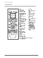
CARACTERÍSTICAS
■ GREEN CRT
■ Turbo Voice
CL-29Z50MQ
Referirse al manual de servicio en GSPN (véase página siguiente) para más información.
GSPN (Global Service Partner Network)
Area
Web Site
North America
service.samsungportal.com
Latin America
latin.samsungportal.com
CIS
cis.samsungportal.com
Europe
europe.samsungportal.com
China
china.samsungportal.com
Asia
asia.samsungportal.com
Mideast & Africa
mea.samsungportal.com
This Service Manual is a property of Samsung Electronics Co.,Ltd.
Any unauthorized use of Manual can be punished under applicable
International and/or domestic law.
© Samsung Electronics Co., Ltd. Jun. 2007
Printed in Korea
AA82-04429A
Table of Contents
Chapter 1 Precaution
■ 1-1 Safety Precautions . . . . . . . . . . . . . . . . . . . . . . . . . . . . . . . . . . . . . . . . . . . . . . . . . . . . . . . . . . . 1-1
■ 1-2 Servicing Precautions . . . . . . . . . . . . . . . . . . . . . . . . . . . . . . . . . . . . . . . . . . . . . . . . . . . . . . . . 1-3
■ 1-3 Static Electricity Precautions . . . . . . . . . . . . . . . . . . . . . . . . . . . . . . . . . . . . . . . . . . . . . . . . . . . 1-4
■ 1-4 Installation Precautions . . . . . . . . . . . . . . . . . . . . . . . . . . . . . . . . . . . . . . . . . . . . . . . . . . . . . . . 1-5
Chapter 2 Product Specification
■ 2-1 Product Features . . . . . . . . . . . . . . . . . . . . . . . . . . . . . . . . . . . . . . . . . . . . . . . . . . . . . . . . . . . . 2-1
■ 2-2 Key Features . . . . . . . . . . . . . . . . . . . . . . . . . . . . . . . . . . . . . . . . . . . . . . . . . . . . . . . . . . . . . . . 2-2
■ 2-3 Specifications Analysis . . . . . . . . . . . . . . . . . . . . . . . . . . . . . . . . . . . . . . . . . . . . . . . . . . . . . . . . 2-3
■ 2-4 Accessories . . . . . . . . . . . . . . . . . . . . . . . . . . . . . . . . . . . . . . . . . . . . . . . . . . . . . . . . . . . . . . . . 2-4
Chapter 3 Alignment & Adjustment
■ 3-1 Service Instruction . . . . . . . . . . . . . . . . . . . . . . . . . . . . . . . . . . . . . . . . . . . . . . . . . . . . . . . . . . . 3-1
■ 3-2 How to Access Service Mode . . . . . . . . . . . . . . . . . . . . . . . . . . . . . . . . . . . . . . . . . . . . . . . . . . . 3-2
■ 3-3 Factory Data . . . . . . . . . . . . . . . . . . . . . . . . . . . . . . . . . . . . . . . . . . . . . . . . . . . . . . . . . . . . . . . . 3-3
■ 3-4 Service Adjustment . . . . . . . . . . . . . . . . . . . . . . . . . . . . . . . . . . . . . . . . . . . . . . . . . . . . . . . . . . 3-15
■ 3-5 Replacements & Calibration . . . . . . . . . . . . . . . . . . . . . . . . . . . . . . . . . . . . . . . . . . . . . . . . . . . . 3-17
Chapter 4 Exploded View & Part List
■ 4-1 CL29Z50MQTXXAO . . . . . . . . . . . . . . . . . . . . . . . . . . . . . . . . . . . . . . . . . . . . . . . . . . . . . . . . . . 4-1
Chapter 5 Electrical Part List
■ 5-1 CL29Z50MQTXXAO . . . . . . . . . . . . . . . . . . . . . . . . . . . . . . . . . . . . . . . . . . . . . . . . . . . . . . . . . . 5-1
Chapter 6 Troubleshooting
■ 6-1 Checkpoints by Error Mode . . . . . . . . . . . . . . . . . . . . . . . . . . . . . . . . . . . . . . . . . . . . . . . . . . . . 6-1
■ 6-2 Troubleshooting Procedures by Error Modes . . . . . . . . . . . . . . . . . . . . . . . . . . . . . . . . . . . . . . . 6-3
■ 6-3 Troubleshooting Procedures by ASS'Y . . . . . . . . . . . . . . . . . . . . . . . . . . . . . . . . . . . . . . . . . . . 6-4
■ 6-4 Troubleshooting by Blocks . . . . . . . . . . . . . . . . . . . . . . . . . . . . . . . . . . . . . . . . . . . . . . . . . . . . . 6-6
Chapter 7 Block Diagram
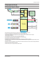
■ 7-1 Overall Block Diagram . . . . . . . . . . . . . . . . . . . . . . . . . . . . . . . . . . . . . . . . . . . . . . . . . . . . . . . . 7-1
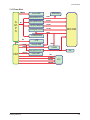
■ 7-2 Partial Block Diagram . . . . . . . . . . . . . . . . . . . . . . . . . . . . . . . . . . . . . . . . . . . . . . . . . . . . . . . . . 7-2
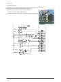
Chapter 8 Wiring Diagram
■ 8-1 Overall Wiring . . . . . . . . . . . . . . . . . . . . . . . . . . . . . . . . . . . . . . . . . . . . . . . . . . . . . . . . . . . . . . . 8-1
■ 8-2 Pin Connection . . . . . . . . . . . . . . . . . . . . . . . . . . . . . . . . . . . . . . . . . . . . . . . . . . . . . . . . . . . . . . 8-2
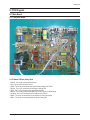
Chapter 9 PCB Diagram
■ 9-1 Main Board . . . . . . . . . . . . . . . . . . . . . . . . . . . . . . . . . . . . . . . . . . . . . . . . . . . . . . . . . . . . . . . . . 9-1
■ 9-2 CRT Board . . . . . . . . . . . . . . . . . . . . . . . . . . . . . . . . . . . . . . . . . . . . . . . . . . . . . . . . . . . . . . . . . 9-3
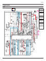
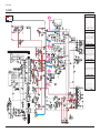
Chapter 10 Schematic Diagram
■ 10-1 MAIN . . . . . . . . . . . . . . . . . . . . . . . . . . . . . . . . . . . . . . . . . . . . . . . . . . . . . . . . . . . . . . . . . . . . 10-1
■ 10-2 POWER . . . . . . . . . . . . . . . . . . . . . . . . . . . . . . . . . . . . . . . . . . . . . . . . . . . . . . . . . . . . . . . . . . 10-2
■ 10-3 Sound . . . . . . . . . . . . . . . . . . . . . . . . . . . . . . . . . . . . . . . . . . . . . . . . . . . . . . . . . . . . . . . . . . . . 10-3
Chapter 11 Operation Instruction & Installation
■ 11-1 Product Features and Functions . . . . . . . . . . . . . . . . . . . . . . . . . . . . . . . . . . . . . . . . . . . . . . . 11-1
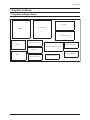
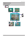
Chapter 12 Disassembly & Reassembly
■ 12-1 Overall Disassembly & Reassembly . . . . . . . . . . . . . . . . . . . . . . . . . . . . . . . . . . . . . . . . . . . . 12-1
Chapter 13 Circuit Description
■ 13-1 Overall Block Description . . . . . . . . . . . . . . . . . . . . . . . . . . . . . . . . . . . . . . . . . . . . . . . . . . . . . 13-1
■ 13-2 Partial Block Description . . . . . . . . . . . . . . . . . . . . . . . . . . . . . . . . . . . . . . . . . . . . . . . . . . . . . 13-2
Chapter 14 Reference Information
■ 14-1 Option Byte . . . . . . . . . . . . . . . . . . . . . . . . . . . . . . . . . . . . . . . . . . . . . . . . . . . . . . . . . . . . . . . 14-1
■ 14-2 Technical Terms . . . . . . . . . . . . . . . . . . . . . . . . . . . . . . . . . . . . . . . . . . . . . . . . . . . . . . . . . . . . 14-2
Precaution
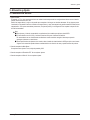
1. Precauciones
Para evitar posibles daños o descargas eléctricas o exposición a radiación, siga las instrucciones de abajo relacionadas con
la seguridad, instalación, servicio y ESD.
1-1 Precauciones de Seguridad
1.
Cerciorece de que todos los dispositivos protectores
estén correctamente instalados incluyendo las manijas
no-metálicas y las cubiertas del compartimiento al instalar o reinstalando el chasis o ensambles del chasis.
2.
Cerciorece que los niños no inserten sus dedos en ninguno
de los espacios que hay entre los gabinetes para evitar que
reciban descargas eléctricas. Los espacios antes mencionados incluyen los agujeros de ventilación de una magnitud demasiado grande entre el tubo de vacio y la máscara
del gabinete, y la instalación incorrecta del gabinete posterior.
5.
Cuidado con los cambios de ingeniería:
Nunca hacer cambios o adiciones al diseño del circuito o a piezas internas en este producto. Ej: No
añadir ningún conector de accesorios de audio o
video. Esto puede causar daño físico. Además,
cualquier cambio o adición al diseño/ingeniería
original invalidarán la garantía.
6.
Advertencia - Chasis caliente:
Algunos chasis de TV's están conectados directamente
a un extremo del cable energía AC por razones eléctricas.
Sin los transformadores de aislamiento, el producto puede ser reparado sin problema cuando el chasis está conectado con el extremo de la fuente puesto a tierra .
Los errores pueden ocurrir cuando la resistencia es menor a 1.0 ㏁
o mayor a 5.2 ㏁.
En estos casos, cerciorece que el dispositivo sea
reparado antes de enviarlo de nuevo al cliente.
3.
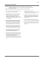
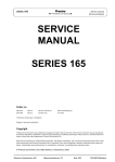
Inspeccione en busca de Fuga de Electricidad (Figura 1-1)
Advertencia: No utilizar transformador de aislamiento para
comprobar la fuga. Sólo use probadores de coriente o sistemas similares que se cumplan con ANSIC 101.1 y las
especificaciones del laboratorio del suscriptor (UL1410,
59.7).
LEAKAGE
CURRENT
TESTER
DEVICE
UNDER
TEST
2-WIRE CORD
ALSO TEST WITH
PLUG REVERSED
(USING AC ADAPTER
PLUG AS REQUIRED)
EARTH
GROUND
Fig. 1-1 AC Prueba de Fuga
Un alto voltaje es mantenido dentro de límites especificados usando piezas de seguridad, calibración y tolerancias. Cuando el voltaje exceda los límites especificados,
compruebe cada pieza especial.
Samsung Electronics
7.
Algunos chasis de TV son distribuidos con un sistema
secundario adicional de puesta a tierra. El sistema secundario está contiguo a la línea de energía AC. Estas
dos sistemas de tierra son separadas en el circuito usando un material de aislamiento irrompible/incambiable.
8.
Cuando alguna pieza, material o cableado aparece
recalentado o dañado, reemplacelas por nuevas inmediatamente. Cuando algún daño o recalentamiento
es detectado, corregir ésto inmediatamente y hacer
una comprobación regular de posibles errores.
(READING SHOULD
NOT BE ABOVE
0.5mA)
TEST ALL
EXPOSED METAL
SURFACES
4.
Asegúrese que el cable de energía AC esté conectado
correctamente, seguir las instrucciones de abajo. Use
el voltímetro para medir el voltaje entre chasis y el punto a tierra. Si la medición es mayor a 1.0V, desenchufe
el cable de energía AC y cambie la polaridad antes de
volver a insertárlo. Medir el voltaje entre el chasis y la
tierra nuevamente.
9. Comprobar el buen estado del conductor, especialmente
el cableado de la antena, algún borde agudo, la energía
AC y el alto voltaje. Comprobar cuidadosamente si el cableado está demasiado apretado, instalado incorrectamente o flojo. Nunca cambiar el espacio entre las partes
y la tarjeta del circuito impreso. Comprobar el cable de
alimentación AC en busca de daños. Mantener partes o
conductores lejos de cualquier material emisor de calor.
1-1
Precaution
10. Indicación de seguridad:
Algunos circuitos eléctricos o materiales relacionados al
dispositivo requieren la atención especial a sus características de seguridad, que no pueden verse a simple vista. Si una parte original se substituye por otra irregular,
la seguridad o las características protectoras se perderán así el nuevo tenga un voltaje más alto o más vatios.
Las partes críticas de seguridad deben soportar-(
! ).
se usando sólo las piezas habituales para los reemplazos (particularmente, resistencia a la llama y especificaciones de intensidad dieléctrica). Las partes o materiales
inhabituales pueden causar descarga eléctrica o fuego.
1-2
Samsung Electronics
Precaution
1-2 Precauciones de Servicio
1 Advertencia: Primero lea cuidadosamente la "Instrucción de Seguridad" en éste manual de servicio.
Cuando hay un conflicto entre el servicio y las instrucciones de saguridad, seguir siempre las
instrucciones de seguridad.
2 Advertencia: Un condensador electrolítico instalado con la polaridad incorrecta puedo estallar.
1.
Las instrucciones de servicio están impresas en el gabinete, el personal de servicio debe seguirlas.
2.
Asegúrese de desconectar el cable de la alimentación
AC de la toma antes de iniciar cualquier reparación.
(a) Remover o re-instalar partes o ensambles.
(b) Desconecte el enchufe eléctrico o conector, si lo hay.
(c) Conecte la parte de prueba en paralelo con el capacitor electrolítico.
3.
Algunas partes sobresalen de la tarjeta impresa. Para
ésto se usan tubos o cinta aislantes con ese propósito.
El cableado interno es sujetado usando hebillas para
evitar el contacto con partes que emitan calor. Esas partes son instaladas por detrás de su posición original.
4.
Después de la reparación, asegúrese de comprobar si los tornillos , partes o cables están instalados correctamente. Cerciórese de no causar daño a las partes reparadas y sus alrededores.
5.
Comprobar el aislamiento entre la lámina del enchufe
AC y cualquier material conductor (panel metálico,
terminal de entrada, clavija auricular, etc).
6.
Procedimiento para Comprobar Aislamiento: Desconecte
el cable eléctrico de la fuente AC y ubique el interruptor
de energia en ON. Conecte medidor de resistencia
(500 V) a las láminas del enchufe de AC.
La resistencia del aislamiento entre la lámina del enchufe
AC y las partes conductoras accesibles debe ser más de
1 ㏁.
Samsung Electronics
7.
Ningún interlock B+ debe dañarse.
Si el discipador de calor no está instalado correctamente,
no debe hacerse la conexión a la fuente AC.
8.
Asegúrese que el conductor de la tierra del tester esté
conectado a la tierra del chasis antes de conectar el
conductor positivo. El conductor tierra del tester debe
removerse de último.
9.
Aguardarse de riesgo de cualquier fuga de corriente
que entre en contacto con el capacitor de alta-capacidad.
10. Los bordes agudos del material metálico pueden causar
daño físico, así que protéjase usando guantes durante
la reparación
1-3
Precaution
1-3 Precauciones con la Electricidad Estática
1.
Algunos dispositivos semiconductores ("Estado sólido")
son vulnerables a la electrostática. Dichos componentes
se conocen como ESD. Los ESD incluyen el circuito integrado y el transistor de efecto de campo. Para evitar
cualquier cualquier daño de materiales por descarga
electrostática, seguir las instrucciones descritas abajo.
2.
Remover cualquier electricidad estática de su cuerpo
haciendo contacto con un punto aterrizado antes de
manipular cualquier parte semi-conductora o ensamble.
Alternativamente, use una pulsera antiestática. (Asegúrese de remover cualquier electricidad estática antes de
conectar la fuente de energía - ésta es una instrucción
de segurida para evitar descargas eléctricas)
3.
Remover el ensamble ESD y colocarlo sobre una superficie conductora como papel aluminio para prevenir
acomulación de carga electrotática.
4.
Not use ningún producto químico en base de Freon.
Dichos productos químicos podrían generar electricidad estática y dañar el ESD.
5.
Para soldar los objetos sólo use los que tienes aterrizada la parte metálica.
6.
Sólo use dispositivos de soldadura anti-estáticos.
La mayoría de dispositivos de soldadura no soportan
una característica anti-estática. Un dispositvo de soldadura sin la característica anti-estática puede almacenar suficiente estática como para dañar el ESD.
7.
No remover el ESD de su empaque protector hasta que
no se vaya a instalar. La mayoría de reemplazos ESD
son cubiertos con material conductivo, que causará un
corto a la unidad ocaionado por la espuma conductora,
papel aluminio o otros materiales conductivos.
8.
Remover el material protector del reemplazo ESD
inmediatamente después de conectarlo al chasis
o circuito de ensamble.
9.
Tener extrema precaución al maniplar cualquier reemplazo ESD destapado. Acciones como rozar la ropa o
levantar su pierna de un piso alfombrado puede generar suficiente estática como para dañar el ESD.
PRECAUCIÓN
Estas instrucciones de servicio son para ser usadas solamente por el personal de servicio calificado. Para reducir
el riesgo de descarga eléctrica no realizar ningún mantenimiento sin tener en cuenta el contenido de instrucciones de
operación a menos que usted esté calificado que sea así.
1-4
Samsung Electronics
Precaution
1-4 Precauciones de Instalación
1.
Por motivos de seguridad, son requeridas más de dos
personas para cargar el producto.
2.
Mantenga el cable eléctrico lejos de cualquier dispositivo que emita calor, una cubierta derretida puede
puede causar incendio o descarga eléctrica.
3.
No ubicar el producto en áreas con de mala ventilación
tal como un estante o un armario. El incremento de la
temperatura interna puede causar incendio.
4.
Doblar el cable de la antena externa al conectarlo al
producto. Esto es una forma de protegerla contra la
humedad. De locontrario, puede causar un incendio
o una descarga eléctrica.
5.
Cercíorece de apagar y desenchufar el cable eléctrico
del toma antes de reubicar el producto. También compruebe que el cable de la antena o conectores externos
si están completamente desenchufadas. El daño en el
cable pueden causar incendio o descarga eléctrica.
Samsung Electronics
6.
Mantener la antena alejada de cualquier cable de alta
tensión e instálela firmemente. El contacto con el cable
del alto voltaje o exceso de temperatura puede causar
incendio o descarga eléctrica
7.
Compruebe los ajustes basicos de la pantalla.
- Posición / tamaño de la image, ajustes de inclinación
1-5
MEMO
1-6
Samsung Electronics
Especificaciones del Producto
2. Especificaciones del Producto
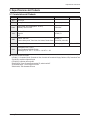
2-1 Características del Producto
Block
CRT
Specfication
Core Parts
- 29" Slim-fit
RF Part
- Analog Tuners
NTSC Tuner(Argemtma option)
Power
- Input Voltage: AC100-240V(Mexico : AC127V)
-Stand-By: Less than 2.6W
STR-X6750F
Video
-1H Comb Filter
-Digital Nr
-BLE
VCT4822_F1
Audio
- OutPut: 10W+10W
VCT4822_F1
- Fuction: Melody on/off, Turbo Voice, Auto Volume, Pseudo Stereo TDA7297SA (10W+10W)
Cabinet
Other
Remark
Front and Back Cabinets
Z30 Design Applied
Material: HIPS
- Development Level : Level 4
- ProtoType Model:CL29Z30PQTXXAX
- Receving(P/G) CH: VHF:2 ~ 13, UHF:14 ~ 69, CATV:1 - 125
■ Funciones de Partes Principales
- VCT4822_F1: Procesador de Sonido, Procesador de Video, Controlador del Procesador de Display y Deflection, OSD y Procesado de Texto
- TDA7297SA : Amplifica la Señal de Sonido
- STR-X6750F: Suministro de Energía HIC
- TDQ-6F/13F2S (Tuner): Procesamiento de señal RF, salida de señal IF
- TECCIO4OSL32A(E) : Tuner Principal PIP-2Tuner
- TMQH2-003A,2 Tuner Secundario PIP-tuner
Samsung Electronics
2-1
Product Specification
2-2 Características Principales
Modelo
CL-29Z50MQ
Voltaje
AC100-240 V(Mejico : AC127V)
Frecuencia de Operación
50/60 Hz
Consumo de Energía
140 Watts
Dimensiones (mm/pulgadas)
Peso (Kg/ lbs)
36.7 x 15.9 x 22.3 inches
934 x 406 x 568 mm
54.5 kg / 120.1 Ibs
■ Configuración H/W
- Adoptado CRT Slim fit 29"
■ Imagen
- System NTSC-M & Pal-M/N
- OSD: Half tone Menu
- DVD-input (Y,Pb,Pr) & S-VHS Option,
- AKB(Auto kinetic Bias)
- Comb Filter: 1H Comb filter
- Auto Peaking Control, Fine Tuneless, Group Delay Correction
■ Sonido
- System: Stereo, Nicam
- Output:10W+10W
- AVL, Melody, Auto Stereo, Auto Mute, Equalizer
■ Características
- Auto program, Sleep timer, Clock
- Caption
- Zoom, Previous channel, Blue Screen, Color Tone
■ In/Out Terminals
- Front: AV IN, S-VHS Input (Rear)
- Rear: 2 AV Input & Component video share
1 Component Input : 480i, RF 1 Input
1 AV Output
■ Remocon
- TM85
■ Power Supply
- 100V ~ 240V, (Mexico : 120V)
■ Power Comsumption
- Standy-by: Less than 2.6W
- Standard Power: 140W
2-2
Samsung Electronics
Product Specification
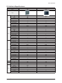
2-3 Análisis de Especificaciones
Model
CL29M6PQ
CL-29Z50MQ
Chassis
KS7A
KS7D
Design
Picture
Sound
Convenience
Screen Size
29"
29"
CRT
FLAT
SLIM-FIT
DNIe Jr.
■
X
Comb Filter
1H
1H
Velocity Modulation
O
X
Video Noise Reduction
O
O
Auto Kinetic Bias
O
O
Color Tone Control
O
O
Tilt Control
O
O
Picture Mode
4 Mode
4 Mode
MTS/SAP
O
O
Output Power(RMS)
15W*2
10W*2
Tweeter
X
X
BBE
X
X
Surround
O
O
Sound Mode
5 Mode
5 Mode
Graphic Equalizer
O
X
Sub-Woofer Speaker
X
X
Auto Volume Leveler
O
O
Melody On/Off
O
O
Turbo Sound
O
O
PIP
2T
2T
Plug & Play
O
O
Zoom Mode
O
O
OSD Demo
O
O
OSD Language
E/F/S/P
E/F/S/P
Previous Channel
O
O
Closed Caption
O
O
On/Off Timer
O
O
Sleep Timer
O
O
Auto Power Off
O
O
Clock
O
O
Channel Scan
X
X
Self-diagnostic System
X
X
Remote Control
TM76
TM85
Remote Surf
O
O
Channel Labelling
O
O
Blue Screen
O
O
Rack
X
X
Voltage
Voltage
100~240
AC120V
Power
Consumption
On
145W
140W
Stand-by
under 3W
under 3W
Jacks
RF Input
R1
R1
A/V Input
S1/R2
S1/R2
Monitor Output
R1
R1
S-VHS Input
S1/R1
S1
Headphone
X
X
DVD Input
O
O
PC Input(VGA)
X
X
Samsung Electronics
2-3
Product Specification
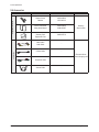
2-4 Accesorios
Accessories that can be purchased
additionally
Supplied Accessories
Accessories
2-4
Item
Item code
Remote Control
Batteries
AA59-00385A
4301-000103
Owner's Instructions
Safety Guide Manual
AA68-03805A
AA68-03242F
Warranty Card
Registration Card
AA68-03727A
-
Video Cable /
Audio Cable
-
S-Video Cable
-
Remark
Samsung
Service center
Electronics Store/
Internal shopping mall
Component Cable
-
Antenna Cable
-
Samsung Electronics
Alineación y Ajuste
3. Alineación y Ajuste
3-1 Instrucción de Servicio
1. Ajuste General :
En general, un TV a color puede proporcionar una calidad visual ideal ajustando las configuraciones básicas como el tamaño
vertical, tamaño horizontal, foco, etc.
Exhibir una imagen blanco y negro en la pantalla para comprobar si la imagen se visualiza claramente. Si hay algunos puntos
'manchados' en la pantalla cuando se visualiza una imagen blanco y negro, desmagnetice la pantalla usando la bobina de desmagnetización. Si los puntos manchados permanecen, re-ajuste la pureza y la convergencia. Esto completa la inspección básica de funcionamiento.
Nota.
■ Estos ajustes y la lista de comprobación son aplicados sólo a modelos que apliquen chasis KS7D.
■ En Norte América use 110V, Sur y América Central use 220v para el sistema de medición.
Es recomendado usar un transformador de aislamiento cuando suministre energía al sistema para prevenir
descargas al sistema o a usted mismo.
■ Estas especificaciones de ajustes se han creado en base al modelo de chasis doméstico KS7D que aplica control remoto.
Algunos de los contenidos pueden haberse cambiado debido a la ubicación de venta y especificaciones del producto.
2. Cuando reemplace la Main Board :
Se requieren estos ajustes: Focus, voltaje de pantalla y W/B.
3. Cuando reemplace el Ensamble CRT: No se requieren ajustes.
4. Cuando reemplace el Side AV : No se requieren ajustes.
Samsung Electronics
3-1
Alignment & Adjustment
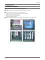
3-2 Cómo Acceder a Modo Servicio
1. Para ingresar al Modo Servicio, presione las teclas en el control remoto de acuerdo a la siguiente secuencia. (en Stand-by)
Mute → 1 → 8 → 2 → Encender
※ Cuando no pueda ingresar al Modo Servicio, repita el procedimiento de arriba.
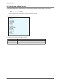
2. La pantalla inicial del Modo Servicio.
Deflection
Video Adujst1
Video Adujst2
Video Adujst3
OPTION
OPTION2
YC DELAY
TEST PATTERN
EEPROM
BUS STOP
CHCKSUM
RESET
G2 ADJUST
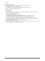
3. Funciones de los botones dentro del Modo de Servicio.
3-2
MENU
Muestra todos los menús
▲ /▼
Mover el cursor para seleccionar un item.
◀/▶
Ajusta el valor de la configuración seleccionada
Samsung Electronics
Alignment & Adjustment
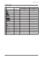
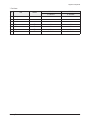
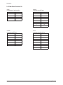
3-3 Datos de fábrica
★ Los items subrayados son a los que aplican ajuste durante el servicio. Ninguno de los otros deben ajustarse.
1. Deflection(NT 60Hz)
No
Item
Remark
29" SLIM
29" SLIM
CL-29Z30PQ
CL-29Z30MQ
1
V Amp
ADJ
42
42
2
V Shift
ADJ
-24
-24
3
H EW
ADJ
-6
-6
4
H Shift
ADJ
130
130
5
V Linearity
ADJ
-3
-3
6
V SC
FIX
43
43
7
H Parabola
ADJ
78
78
8
Upper Corner
ADJ
11
11
9
Lower Corner
ADJ
-29
-29
10
Upper Corner6
FIX
-18
-18
11
Lower Corner6
FIX
3
3
12
H Trapezium
ADJ
29
29
13
Bow
ADJ
2
2
14
Angle
FIX
-1
-1
15
EHT Time
FIX
20
20
16
EHT Threshold
FIX
1
1
17
EHT Vertical
FIX
0
0
18
EHT Horizontal
FIX
24
24
19
EHT Vertical2
FIX
4
4
20
EHT Horizontal2
FIX
7
7
Samsung Electronics
3-3
Alignment & Adjustment
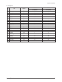
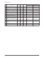
2. Deflection(PAL 50Hz)
No
Item
Remark
29" SLIM
29" SLIM
CL-29Z30PQ
CL-29Z30MQ
1
V Amp
ADJ
4
4
2
V Shift
ADJ
-5
-5
3
H EW
ADJ
2
2
4
H Shift
ADJ
-17
-17
5
V Linearity
ADJ
0
0
6
V SC
FIX
0
0
7
H Parabola
ADJ
2
2
8
Upper Corner
ADJ
-7
-7
9
Lower Corner
ADJ
-5
-5
10
Upper Corner6
ADJ
4
4
11
Lower Corner6
ADJ
6
6
12
H Trapezium
ADJ
-8
-8
13
Bow
FIX
2
2
14
Angle
FIX
0
0
15
EHT Time
FIX
20
20
16
EHT Threshold
FIX
1
1
17
EHT Vertical
FIX
0
0
18
EHT Horizontal
FIX
24
24
19
EHT Vertical2
FIX
4
4
20
EHT Horizontal2
FIX
7
7
3-4
Samsung Electronics
Alignment & Adjustment
0 V-AMP
6
H-Parabola
1 V-Shift
7
Upper Coner
2 H EW
8
Low Coner
3 H-Shift
9
H-Trapezium
4 V-Linearity
10 BOW
5 V SC
11 Angle
Samsung Electronics
3-5
Alignment & Adjustment
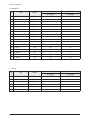
3. Video Adjust 1
No
Item
Remark
29" SLIM
29" SLIM
CL-29Z30PQ
CL-29Z30MQ
1
R Cutoff
ADJ
127
127
2
G Cutoff
FIX
127
127
3
B Cutoff
ADJ
127
127
4
R Drive
ADJ
127
127
5
G Drive
FIX
127
127
6
B Drive
ADJ
127
127
7
Sub Bright
ADJ
52
52
8
Sub Contrast
ADJ
32
32
9
Sub Color
FIX
2
2
10
Sub Tint
FIX
46
46
11
AKB Option
FIX
1
1
12
BCL Threshold
FIX
19
19
13
BCL Gain
FIX
240
240
14
BCL Time
FIX
255
255
15
Sub Sharpness
FIX
12
12
16
Pilot Low
FIX
7
7
17
Pilot High
FIX
13
13
18
V-Mute(x100ms)
FIX
3
3
19
BCL TCUP
FIX
100
100
3-6
Samsung Electronics
Alignment & Adjustment
4. Video Adjust 2
No
Item
Remark
29" SLIM
29" SLIM
CL-29Z30PQ
CL-29Z30MQ
1
VSU
FIX
2
2
2
Melody Volume
FIX
5
5
3
HB Start
FIX
159
159
4
HB Stop
FIX
149
149
5
RF AGC
FIX
4
4
6
VM Gain
FIX
0
0
7
VM Delay
FIX
0
0
8
V Peaking
FIX
12
12
9
BLE Tilt
FIX
12
12
10
BLE Gain
FIX
1
1
11
BLE Mode
FIX
2
2
12
BLE Break
FIX
1
1
13
CTI Gain
FIX
1
1
14
CTI Coring
FIX
15
15
15
LTI Gain
FIX
15
15
16
D-EHT Time
FIX
5
5
17
DCT Ratio
FIX
50
50
18
VSP COMB
FIX
3
3
Samsung Electronics
3-7
Alignment & Adjustment
5. Video Adjust 3
No
Item
Remark
29" SLIM
29" SLIM
CL-29Z30PQ
CL-29Z30MQ
1
NR Off Value
FIX
3
3
2
Gamma Mode
FIX
1
1
3
Gamma Correction
FIX
70
70
4
BST StartPoint
FIX
145
145
5
BST Gain(B)
FIX
50
50
6
DPWL Gain
FIX
80
80
7
DPWL Start
FIX
185
185
8
PIP Contrast
FIX
8
8
9
PIP Tint
FIX
57
57
10
PIP Color
FIX
6
6
11
PIP PAL V.Pos
FIX
24
24
12
PIP NTSC V.Pos
FIX
24
24
13
PIP H.Pos
FIX
46
46
14
PIP R Cutoff
FIX
6
6
15
PIP B Cutoff
FIX
9
9
16
PIP R Drive
FIX
161
161
17
PIP B Drive
FIX
141
141
29" SLIM
29" SLIM
CL-29Z30PQ
CL-29Z30MQ
6. YC Delay
No
Item
Remark
1
PAL Delay
FIX
0
0
2
SECAM Delay
FIX
-2
-2
3
NTSC Delay
FIX
0
0
4
PAL(AV) Delay
FIX
0
0
5
SECAM(AV) Delay
FIX
-3
-3
6
NTSC(AV) Delay
FIX
0
0
3-8
Samsung Electronics
Alignment & Adjustment
7. Test Pattern
No
Item
Remark
29" SLIM
29" SLIM
CL-29Z30PQ
CL-29Z30MQ
1
G2 Adjust
-
-
-
2
Read Cut
-
-
-
3
Read Drive
-
-
-
4
IBRM
FIX
180
180
5
WDRM
FIX
50
50
6
CDL
FIX
254
254
7
COLR G B
FIX
50 / 50 / 50
50 / 50 / 50
Samsung Electronics
3-9
Alignment & Adjustment
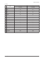
8. EEPROM
No
Item
Remark
MIN
MAX
29" SLIM
29" SLIM
CL-29Z30PQ
CL-29Z30MQ
0
Dynamic Contrast
FIX
0
255
100
100
1
Dynamic Brightness
FIX
0
255
45
45
2
Dynamic Sharpness
FIX
0
255
65
65
3
Dynamic Color
FIX
0
255
43
43
4
Dynamic Tint
FIX
0
255
50
50
5
Standard Contrast
FIX
0
255
82
82
6
Standard Brightness
FIX
0
255
45
45
7
Standard Sharpness
FIX
0
255
50
50
8
Standard Color
FIX
0
255
45
45
9
Standard Tint
FIX
0
255
50
50
10
Movie Contrast
FIX
0
255
50
50
11
Movie Brightness
FIX
0
255
55
55
12
Movie Sharpness
FIX
0
255
25
25
13
Movie Color
FIX
0
255
40
40
14
Movie Tint
FIX
0
255
50
50
15
255
255
16
255
255
17
255
255
18
255
255
10
10
19
DVD SUB TINT
FIX
0
20
16:9 V-SHIFT
FIX
0
100
15
15
21
16:9 PARAVOLA
FIX
0
100
5
5
22
PIP BRIGHTNESS
FIX
0
15
0
0
23
Double TTX Contrast
FIX
255
255
24
TTX V Position
FIX
0
255
255
255
25
TTX H Position
FIX
0
255
255
255
26
TTX Contrast
FIX
0
255
255
255
27
TTX Brightness
FIX
0
255
255
255
28
OSD Contrast
FIX
0
255
115
115
29
OSD Brightness
FIX
0
255
15
15
30
Double TTX H Position
FIX
0
255
255
255
31
Standard Equ100(Std BASS)
FIX
0
8
50
50
32
Standard Equ300(Std TREBLE)
FIX
0
13
50
50
33
Standard Equ1K(Music BASS)
FIX
0
14
85
85
34
Standard Equ3K(Music TREBLE)
FIX
0
13
70
70
35
Standard 10K(Movie BASS)
FIX
0
12
95
95
36
Music Equ100(Movie TREBLE)
FIX
0
18
50
50
37
Music Equ300(Speech BASS)
FIX
0
14
40
40
3-10
Samsung Electronics
Alignment & Adjustment
No
Item
Remark
MIN
MAX
29" SLIM
29" SLIM
CL-29Z30PQ
CL-29Z30MQ
38
Music Equ1K(Speech TREBLE)
FIX
0
11
50
50
39
Music Equ3K
FIX
0
14
255
255
40
Music 10K
FIX
0
18
255
255
41
Movie Equ100
FIX
0
22
255
255
42
Movie Equ300
FIX
0
15
255
255
43
Movie Equ1K
FIX
0
11
255
255
44
Movie Equ3K
FIX
0
12
255
255
45
Movie 10K
FIX
0
13
255
255
46
Speech Equ100
FIX
0
6
255
255
47
Speech Equ300
FIX
0
11
255
255
48
Speech Equ1K
FIX
0
14
255
255
49
Speech Equ3K
FIX
0
13
255
255
50
Speech 10K
FIX
0
11
255
255
51
Brightness(RGB/DVD)
FIX
0
255
6
6
52
Contrast(RGB/DVD)
FIX
0
63
42
42
53
U Saturation(RGB/DVD)
FIX
0
63
44
44
54
V saturation(RGB/DVD)
FIX
0
63
43
43
55
V/FBL Delay
FIX
0
255
85
85
56
CrCb Delay
FIX
0
255
84
84
57
d/w h-position
FIX
0
255
255
255
58
d/w -blanking 1
FIX
0
255
255
255
59
d/w -blanking 2
FIX
0
255
255
255
60
PIP G CUTOFF
FIX
0
255
4
4
61
PIP G DRIVE
FIX
0
255
170
170
62
OSD/PIP BRIGHT BALANCE
FIX
0
31
31
31
63
PIP BRIGHT OFFSET
FIX
0
255
86
86
64
MDB_STRENGTH
FIX
0
127
68
68
65
MDB_HARMONIC
FIX
0
127
37
37
66
MDB_HP
FIX
0
30
9
9
67
MDB_LP
FIX
0
30
11
11
68
MDB_LIM
FIX
0
255
252
252
69
MDB_CUTOFF
FIX
0
40
12
12
70
EHT POSITION 1
FIX
0
255
5
5
71
EHT POSITION 2
FIX
0
255
249
249
72
3.4CH SLLTHD (TV-NO NOISE)
FIX
0
3
0
0
73
CH SLLTHD (TV-NO NOISE)
FIX
0
3
0
0
74
LNA Operating Point
FIX
0
255
166
166
75
SLLTHDV(TV NO NOISE)
FIX
0
6
0
0
Samsung Electronics
3-11
Alignment & Adjustment
No
Item
Remark
MIN
MAX
29" SLIM
29" SLIM
CL-29Z30PQ
CL-29Z30MQ
76
LNA Default
FIX
0
1
0
0
77
LNA SWITCH
FIX
0
1
0
0
78
LMIXOFS
FIX
0
13
13
13
79
H-OUTDEL
FIX
0
255
72
72
80
CR-P Initial
FIX
0
255
4
4
81
CR-I Initial
FIX
0
255
5
5
82
DRX_CR_AMP_TH
FIX
0
255
10
10
83
Over Modulation Return Counter
FIX
0
255
100
100
84
VCR Mode Counter
FIX
0
255
5
5
85
"VID_AMP_HEAD_BS(In the modulation)"
FIX
0
255
40
40
86
CR_P (In the Over Modulation)
FIX
0
255
4
4
87
"THRSEL(picture shaking when weak
signal)"
FIX
0
255
2
2
88
SLLTHDVP
FIX
0
255
1
1
89
EEP_BC_MIN_LIMIT
FIX
0
255
150
150
3-12
Samsung Electronics
Alignment & Adjustment
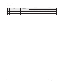
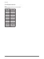
9. OPTION
No
Item
29" SLIM
29" SLIM
CL-29Z30PQ
CL-29Z30MQ
1
System
CL
CL
2
ACS
Off
Off
3
AV Jack
2RCA+S+DVD
2RCA+S+DVD
4
Tilt
On
On
5
Vchip
Off
Off
6
Caption
On
On
7
PIP
Off
2-Tuner
8
LNA
Off
On
9
Auto On
Off
Off
10
StandBy LED
Off
Off
11
Philippines(AV MULTI)
Off
Off
12
Osd Language
English
English
13
FM Radio
Off
Off
14
Antenna Disp
Off
Off
15
Hi-Deviation
Off
Off
16
Plug & Play
On
On
17
DNIe Jr
Off
Off
18
Volume Curve
Small
Small
19
Color Matrix
Japan
Japan
20
PWM/Parabola
Parabola
Parabola
Samsung Electronics
3-13
Alignment & Adjustment
11. White Balance
No
Item
Remark
29" SLIM
29" SLIM
CL-29Z30PQ
CL-29Z30MQ
1
H
-
269± 3/274± 3/40± 0.3
269± 3/274± 3/40± 0.3
2
L
-
269± 3/274± 3/2.0± 0.2
269± 3/274± 3/2.0± 0.2
3-14
Samsung Electronics
Alignment & Adjustment
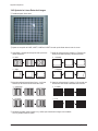
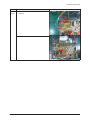
3-4 Ajuste de Servicio
3-4-1 Ajuste del Tamaño de la Imagen
■ Dado que el chasis KS7D tiene datos de ajuste dentro de Datos Fábrica, El tamaño de la imagen tiene que ajustarse cuando
reemplace la Main Board, de acuerdo al siguiente procedimiento.
① Pantalla del Patrón Lion.
② Presionar "Apagar → Mute → 1 → 8 → 2 → Encender"
usando el control remoto e ingrese al Modo Fábrica.
③ Ingrese al Modo Deflection.
④ Ajuste items V-AMP, V-SHIFT, H-AMP y H-SHIFT de modo
que el anchura sea 5 y el altura 4.
44
55
4 4
55
5 5
5 5
44
4 4
Samsung Electronics
3-15
Alignment & Adjustment
3-4-2 Ajuste de las Líneas Rectas de la Imagen
① Pantalla del patrón Cross Hatch.
② Ajustar con excepción de V-AMP, V-SHIFT, H-AMP and H-SHIFT de modo que las líneas rectas se vean sin curvas.
③ Ajuste BOW y configuracón de Angle de modo que la línea
central quede recta.
④ Ajuste las configuraciones H-Parabola y H-Trapezium de
modo que las líneas izquierda y derecha sean rectas.
10 BOW
6
H-Parabola
11 Angle
9
H-Trapezium
⑤ Ajuste las configuraciones de Upper Corner y Low Corner
de modo que los extremos de las líneas sean rectas.
⑥ Ajuste las configuraciones V-Linearity y V-SC de modo que
los intervalos de las líneas horizontales seas uniformes.
7
Upper Coner
4 V-Linearity
8
Low Coner
5 V SC
⑦ Al finalizar los ajustes, exhibir el patrón Lion y verificar que el tamaño de la imagen no ha cambiado.
Si no hay cambio, finalice los ajustes.
3-16
Samsung Electronics
Alignment & Adjustment
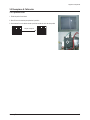
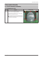
3-5 Reemplazos & Calibración
3-5-1 Ajuste de Focus
1. Exhibir el patrón Cross Hatch.
2. Gire el Focus a la derecha para optimizar la posición.
3. Gire lentamente Focus a la derecha de modo que la línea cruzada sea vea lo más claro posible.
Después del Ajuste
Focus
Samsung Electronics
3-17
Alignment & Adjustment
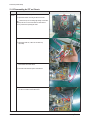
3-5-2 Ajuste del Voltaje de la Pantalla
1. "Apagar → Mute → 1 → 8 → 2 → Encender" para ingresar al Modo Servicio.
2. Aplicar el patrón Toshiba.
Screen
3. Use control remoro para ir al modo "G2 Adjust" manualmente.
4. Gire VR Screen en FBT y confirme que los caracteres de abajo cambien de Rojo a Verde.
3-18
Samsung Electronics
Alignment & Adjustment
3-5-3 Ajuste de Balance de Blancos
1. "Apagar → Mute → 1 → 8 → 2 → Encender" para ingresar al Modo Servicio.
2. Inicializar todos los ajustes a los valores apropiados al correspondiente modelo.
3. Aplicar el patrón Toshiba y ajuste el Balance de Blancos usando CA100 con las coordenadas del modelo correspondiente.
4. Ingrese a Video Adjust1 del Modo de Servicio. Ajuste Low/Light.
- Ajuste Sub Bright to set Y.
- Ajuste B Cutoff to set y.
- Ajuste R Cutoff to set x.
5. Ingrese a Video Adjust1 del Modo de Servicio. Ajuste High/Light.
- Ajuste Sub Contrast to set Y.
- Ajuste B Drive to set y.
- Ajuste R Drive to set x.
6. Chequee Low/Light y reajústela si sus valores han cambiado.
7. Si ha reajustado Low/Light, reajuste High/Light hasta que los dos valores sean idénticos a las coordenadas del modelo
correspondiente.
※ Datos Estándar de Balance de Blancos
No
Item
1
Balance de Blancos
29" SLIM
29" SLIM
CL-29Z30PQ
CL-29Z30MQ
269± 3/274± 3/40± 0.3
269± 3/274± 3/2.0± 0.2
269± 3/274± 3/40± 0.3
269± 3/274± 3/2.0± 0.2
Required Adjustment
White Balance
(Standardization Applied)
3-5-4 Lista de Comprobación para los Ajustes de Voltaje de Pantalla y Balance de Blancos
1. El Voltaje de Pantalla y el Balance de Blancos están conectados, y los dos tienen que ser configurados en los valores correctos.
2. Ajuste el Balance de Blancos después que el Voltaje de Pantalla sea ajustada, y comprobar si el Voltaje Pantalla es normal
después de ajustar el Balance de Blancos.
3. Si se reajusta el Balance de Blancos, comprobar el Voltaje Pantalla nuevamente.
4. Cuando finalice el ajuste, comprobar los siguientes puntos.
- Si hay un punto en la pantalla al apagar/encender el TV, ajuste el Voltaje de Pantalla nuevamente.
- Si hay una línea fantasma en la pantalla, ajuste el Voltaje de Pantalla nuevamente.
Samsung Electronics
3-19
MEMO
3-20
Samsung Electronics
Exploded View & Part List
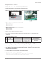
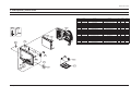
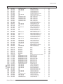
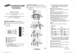
4. Vista Explotada y Lista de Partes
4-1 CL29Z50MQTXXAO
T0074
M0006
T0268
T0063
T0065
T0003
T0091
Loc.No.
Code No.
Description
Specification
Q'ty
SA/SNA
CIS7
AA61-60003J
SPRING ETC-CS
-,SUS304,-,-,OD6,N7,OD6,-,
1
S.N.A
M0006
AA63-01563D
COVER-REAR
29Z50(HQ,SAMEX),HIPS,T2.7,HB,
1
S.N.A
M0014
AA94-15816B
ASSY PCB MAIN
CL29Z30MQTXXAZ,KS7D,TIME C
1
S.A
M0112
AA63-01562F
COVER-FRONT
29Z50(HQ,SAMEX,SEDA),HIPS,T2
1
S.N.A
T0003
AA96-04725P
ASSY COVER P-FRONT
29Z50(HQ,SAMEX,SEDA),
1
S.A
T0022
AA64-04437A
KNOB CONTROL
29Z50,ABS,HB,GR515,SVM3012
1
S.N.A
T0023
AA64-04434A
KNOB POWER
29Z50,ABS,HB,GR515,BKN3576
1
S.N.A
T0054
AA64-04428A
KNOB-DECORATION
29Z50,ABS,HB,GR515,AL
1
S.N.A
T0063
AA03-00486A
CRT COLOR
A68QFZ893X101,0,1.10,13.3,1.33
1
S.A
T0065
AA94-15815B
ASSY PCB CRT
WITH OUT CRT PCB
1
S.A
T0070
AA61-01424A
HOLDER-CHASSIS
32Z30,HIPS V0,T2.0,-,-,G4
1
S.N.A
T0074
AA59-00385A
REMOCON
TIMECOP,TM85,20p samsung,39,INTE
1
S.A
T0091
AA94-15813A
ASSY PCB MISC-A/V SIDE
,KS7D,TIME COP
1
S.A
T0098
AA94-16132A
ASSY PCB MISC-CONTROL
CT-29Z50,K71A,PRIM
1
S.A
T0105
AA94-15802A
ASSY PCB MISC-TACT S/W
K63A,NATURAL
1
S.A
T0175
AA96-04414A
ASSY SPEAKER P
8ohm,10W,L:YELLOW/BLAVK60
1
S.A
T0268
AA39-10006X
CBF-POWER CORD
-,-,KKP419C,3P,-,-,BLK,-,
1
S.A
T0299
AA64-04438A
WINDOW-RMC LED
29Z50(HQ,SAMEX,SEDA),PC,C
1
S.N.A
Remark
M0112
T0175
T0105
M0014
T0299
T0098
T0054
CIS7
T0070
T0022
T0023
Samsung Electronics
4-1
Lista de Partes Eléctricas
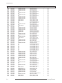
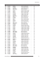
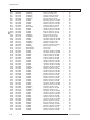
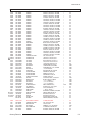
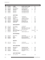
5. Lista de Partes Eléctricas
5-1 CL29Z50MQTXXAO
Loc.No.
Code No.
Description
Specification
Q'ty
SA/SNA
Remark
ASSY CHASSIS
M0017
AA91-10812A
ASSY CHASSIS
CL29Z50MQTXXAP
1
S.N.A
T0105
CC01
CN330
DC01
DC02
DZC01
L0405
M2893
PCB
RC01
RC02
RM01
T0245
T0313
AA94-15802A
2401-002291
3711-001031
0401-000005
0401-000005
0403-000508
0601-000262
BP39-00033C
AA41-01198A
2001-000020
2001-000281
0609-001202
0202-001492
3404-000243
AA97-16522A
ASSY PCB MISC-TACT S/W
C-AL
HEADER-BOARD TO CABLE
DIODE-SWITCHING
DIODE-SWITCHING
DIODE-ZENER
LED
LEAD CONNECTOR
PCB SUB-TACT S/W
R-CARBON(S)
R-CARBON
Module Remocon
SOLDER-WIRE FLUX
SWITCH-TACT
ASSY AUTO-TACT S/W
K63A,NATURAL
47uF,20%,16V,GP,TP,6.3x5,5
BOX,6P,1R,2.5MM,AN
1N4148,75V,150mA,DO-35,T
1N4148,75V,150mA,DO-35,T
MTZJ5.6B,5.45-5.73V,500mW,DO
ROUND,RED,5mm,700nm
K62A(CORE),UL1007#26,UL/C
CT-32Z40HDK,FR-1,1L,A,1
22OHM,5%,1/2W,AA,TP,2.4X6.4M
100OHM,5%,1/8W,AA,TP,1.8X3.2MM
HORIZONTAL,12.4mm,TR
HSE-02 LFM48 SR-34 S,-,
15V,20mA,160gf,6x3.4mm,SPST
TXS3082WHX/XAA,K63A,N
1
1
1
1
1
1
1
1
1
1
1
1
0.001
1
1
S.A
S.A
S.A
S.A
S.A
S.A
S.A
S.A
S.N.A
S.A
S.A
S.A
S.N.A
S.A
S.N.A
T0091
C701
C702
C703
C704
DZ701
DZ702
JA332
JA333
L2514
L2514
L701
L702
L703
L704
M2893
PCB
R701
R702
R703
T0245
T0245
T0569
AA94-15813A
2202-000231
2202-000121
2202-000121
2202-000231
0403-000720
0403-000720
3722-000544
3722-001663
3301-000287
3301-000287
2701-000114
2701-000168
2701-000168
2701-000114
AA39-20068J
AA41-01212A
2001-000969
2001-000969
2001-000969
0202-001492
AA39-20070B
AA97-16525A
ASSY PCB MISC-A/V SIDE
C-CERAMIC,MLC-AXIAL
C-CERAMIC,MLC-AXIAL
C-CERAMIC,MLC-AXIAL
C-CERAMIC,MLC-AXIAL
DIODE-ZENER
DIODE-ZENER
JACK-VHS
JACK-PIN
BEAD-AXIAL
BEAD-AXIAL
INDUCTOR-AXIAL
INDUCTOR-AXIAL
INDUCTOR-AXIAL
INDUCTOR-AXIAL
LEAD CONNECTOR
PCB SUB-SIDE A/V
R-CARBON
R-CARBON
R-CARBON
SOLDER-WIRE FLUX
LEAD CONNECTOR-ASSY
ASSY AUTO-A/V SIDE
,KS7D,TIME COP
0.33NF,10%,50V,Y5P,T
0.1nF,10%,50V,Y5P,-,
0.1nF,10%,50V,Y5P,-,
0.33NF,10%,50V,Y5P,T
MTZJ9.1B,8.57-9.01V,500mW,DO
MTZJ9.1B,8.57-9.01V,500mW,DO
4P,AG,BLK,STRAIGHT
3P,NI,RED/WHT/YEL,STRAIGHT
,3.5x1.0x6.0mm,3000mA,TP,,,50
,3.5x1.0x6.0mm,3000mA,TP,,,50
10UH,10%,2534
3.3UH,5%,2534
3.3UH,5%,2534
10UH,10%,2534
,8P,600MM,YBNH250-08,6709
KS7D,FR-1,-,00,1.6,245*
75OHM,5%,1/8W,AA,TP,1.8X3.2MM
75OHM,5%,1/8W,AA,TP,1.8X3.2MM
75OHM,5%,1/8W,AA,TP,1.8X3.2MM
HSE-02 LFM48 SR-34 S,-,
,7P,600,YBNH025-07,6
,KS7D,TIME COP
1
1
1
1
1
1
1
1
1
1
1
1
1
1
1
1
1
1
1
1
0.003
1
1
S.A
S.A
S.A
S.A
S.A
S.A
S.A
S.A
S.A
S.N.A
S.N.A
S.A
S.A
S.A
S.A
S.A
S.N.A
S.A
S.A
S.A
S.N.A
S.A
S.N.A
T0065
C504
C506
C507
C508
C509
C510
CN330
D501
D502
D503
D504
DZ501
DZ502
DZ503
EL501
AA94-15815B
2301-001259
2401-000430
2401-000430
2201-000723
2201-002147
2201-002147
3711-003241
0401-000006
0401-000006
0401-000006
0402-000546
0403-000720
0403-000720
0403-000720
6042-000001
ASSY PCB CRT
C-FILM,LEAD-PPF
C-AL
C-AL
C-CERAMIC,DISC
C-CERAMIC,DISC
C-CERAMIC,DISC
HEADER-BOARD TO CABLE
DIODE-SWITCHING
DIODE-SWITCHING
DIODE-SWITCHING
DIODE-RECTIFIER
DIODE-ZENER
DIODE-ZENER
DIODE-ZENER
EYELET
WITH OUT CRT PCB
100nF,5%,400V,TP,19x8x16
10uF,20%,250V,GP,TP,10x16mm,5m
10uF,20%,250V,GP,TP,10x16mm,5m
4.7NF,20%,3KV,Y5U,TP,16X5
2.7NF,10%,500V,Y5P,TP,10X
2.7NF,10%,500V,Y5P,TP,10X
BOX,14P,1R,2.5MM,S
BAV21,250V,200mA,DO-35,T
BAV21,250V,200mA,DO-35,T
BAV21,250V,200mA,DO-35,T
TVR10G,400V,1A,DO-41,TP
MTZJ9.1B,8.57-9.01V,500mW,DO
MTZJ9.1B,8.57-9.01V,500mW,DO
MTZJ9.1B,8.57-9.01V,500mW,DO
ID2.2,OD2.7,L3.1,NI+SN,BSP3-1/2H
1
1
1
1
1
1
1
1
1
1
1
1
1
1
1
1
S.A
S.A
S.A
S.A
S.A
S.A
S.A
S.A
S.A
S.A
S.A
S.A
S.A
S.A
S.A
S.N.A
Samsung Electronics
5-1
Electrical Part List
Loc.No.
Code No.
EL502
F101
GT501
GT502
GT503
GT504
IC501
L503A
M0081
M2893
PCB
Q503
R501
R501H
R502H
R504
R505
R511
R514
R550
R551
R553
T0074
T0100
T0175
T0245
T0245
T0310
T0310
T0310
T0310
V999S
6042-000001
2901-000299
BH71-40300A
BH71-40300A
BH71-40300A
BH71-40300A
AA96-50311N
2702-001092
6003-000334
AA39-00376B
AA41-01187A
0501-000283
2001-000281
2002-001008
2002-001008
2001-000281
2001-000281
2002-001008
2001-001062
2001-000449
2001-000761
2001-000411
1201-002114
AA97-16527B
AA62-30175D
AA39-20010D
0202-001492
4715-000001
4715-000001
4715-000001
4715-000001
3704-001197
EYELET
FILTER-EMI ON BOARD
PIN-HINGE
PIN-HINGE
PIN-HINGE
PIN-HINGE
ASSY HEAT SINK P
INDUCTOR-RADIAL
SCREW-TAPTITE
LEAD CONNECTOR
PCB CRT
TR-SMALL SIGNAL
R-CARBON
R-COMPOSITION
R-COMPOSITION
R-CARBON
R-CARBON
R-COMPOSITION
R-CARBON(S)
R-CARBON
R-CARBON
R-CARBON
IC-VIDEO AMP
ASSY AUTO-CRT
HEAT SINK-PS
LEAD CONNECTOR-ASSY
SOLDER-WIRE FLUX
SURGE ABSORBER
SURGE ABSORBER
SURGE ABSORBER
SURGE ABSORBER
SOCKET-CRT
ID2.2,OD2.7,L3.1,NI+SN,BSP3-1/2H
-,6A,UL/CSA,-,9x7.5,
BRASS,D2.36!,HEAT/SINK,SN
BRASS,D2.36!,HEAT/SINK,SN
BRASS,D2.36!,HEAT/SINK,SN
BRASS,D2.36!,HEAT/SINK,SN
AA62-30175D,TDA6109JF,S
2.2uH,10%,4x6mm
RH,+,-,2S,M3,L6,ZPC(WHT),S
ET-PAL CIS,UL1007/1185#26
CS29M20,FR-1,9L,00,1.6T,245*245,
KSA539,PNP,400mW,TO-92,T
100OHM,5%,1/8W,AA,TP,1.8X3.2MM
1.8Kohm,10%,1/2W,AA,TP,3.7
1.8Kohm,10%,1/2W,AA,TP,3.7
100OHM,5%,1/8W,AA,TP,1.8X3.2MM
100OHM,5%,1/8W,AA,TP,1.8X3.2MM
1.8Kohm,10%,1/2W,AA,TP,3.7
10MOHM,5%,1/2W,AA,TP,2.4X6.4
2.2KOHM,5%,1/8W,AA,TP,1.8X3.2MM
430OHM,5%,1/8W,AA,TP,1.8X3.2MM
18KOHM,5%,1/8W,AA,TP,1.8X3.2MM
TDA6109JF,SDIP,9P,18.5mm,-,
M0014
C107
C108
C112
C212
C299
C301
C302
C303
C304
C305
C306
C307
C308
C400
C401
C402
C403
C404
C405
C406
C406A
C408
C409
C410
C411
C412
C413
C414
C415
C416
C420
C421
C424
C607
AA94-15816B
2202-002037
2401-003578
2202-002037
2305-000665
2305-000665
2301-000342
2201-000192
2401-000360
2401-000360
2305-000285
2301-000148
2401-000050
2305-000411
2305-001037
2301-000383
2401-000302
2201-000599
2305-000382
2301-001338
2301-001271
2301-001420
2201-000556
2401-001397
2401-001397
2201-000556
2401-001527
2201-000556
2305-000237
2301-001259
2305-000237
2306-000122
2301-000383
2201-000132
2202-000231
ASSY PCB MAIN
C-CERAMIC,MLC-AXIAL
C-AL
C-CERAMIC,MLC-AXIAL
C-FILM,LEAD-PEF
C-FILM,LEAD-PEF
C-FILM,LEAD-PEF
C-CERAMIC,DISC
C-AL
C-AL
C-FILM,LEAD-PEF
C-FILM,LEAD-PEF
C-AL
C-FILM,LEAD-PEF
C-FILM,LEAD-PEF
C-FILM,LEAD-PEF
C-AL
C-CERAMIC,DISC
C-FILM,LEAD-PEF
C-FILM,LEAD-OTHER
C-FILM,LEAD-PPF
C-FILM,LEAD-PPF
C-CERAMIC,DISC
C-AL
C-AL
C-CERAMIC,DISC
C-AL
C-CERAMIC,DISC
C-FILM,LEAD-PEF
C-FILM,LEAD-PPF
C-FILM,LEAD-PEF
C-FILM,LEAD-PPF
C-FILM,LEAD-PEF
C-CERAMIC,DISC
C-CERAMIC,MLC-AXIAL
5-2
Description
Specification
Q'ty
SA/SNA
-,SECC,T1.0,-,33X15X30 FT-2
,1P,400,YFH800-01,S,
HSE-02 LFM48 SR-34 S,-,
1000V,+50-10%,-,-,1000V,+50-10%,-,-,1000V,+50-10%,-,-,1000V,+50-10%,-,-,8P+SEN,29PI,22.5PI,NI+SN,-
1
1
1
1
1
1
1
1
1
1
1
1
1
1
1
1
1
1
1
1
1
1
1
1
1
1
0.003
1
1
1
1
1
S.N.A
S.A
S.N.A
S.N.A
S.N.A
S.N.A
S.N.A
S.A
S.N.A
S.A
S.N.A
S.A
S.A
S.A
S.A
S.A
S.A
S.A
S.A
S.A
S.A
S.A
S.A
S.N.A
S.N.A
S.A
S.N.A
S.A
S.A
S.A
S.A
S.A
CL29Z30MQTXXAZ,KS7D,TIME C
100nF,80-20%,50V,Y5V
1000uF,20%,10V,GP,TP,8x20mm,5
100nF,80-20%,50V,Y5V
100nF,5%,63V,TP,7.5x4.0x
100nF,5%,63V,TP,7.5x4.0x
2.2nF,5%,50V,TP,7.4x3.9x
0.01nF,0.25pF,500V,C0G,-,
100uF,20%,50V,GP,TP,8x11.5,5
100uF,20%,50V,GP,TP,8x11.5,5
220NF,5%,100V,TP,10.5X5.
10nF,5%,100V,TP,7x3.2x7m
10uF,20%,16V,GP,TP,5x11,2.5
470nF,5%,50V,TP,7.3x4.8x
330nF,5%,63V,TP,7.5x5.5x
10nF,5%,50V,TP,6x7x3.2mm
100uF,20%,25V,GP,TP,6.3x11,5
0.56NF,10%,500V,Y5P,TP,5.
4.7nF,5%,400V,TP,-,5mm
0.68NF,5%,1.6KV,BK,28X
510nF,5%,400V,BK,26x13.5
1200nF,5%,400V,BK,31x16.
0.47NF,10%,500V,Y5P,TP,5.
470uF,20%,25V,GP,TP,10x16,5
470uF,20%,25V,GP,TP,10x16,5
0.47NF,10%,500V,Y5P,TP,5.
47uF,20%,250V,HR,TP,13x25mm,5m
0.47NF,10%,500V,Y5P,TP,5.
1uF,5%,63V,TP,7.5x15.5mm
100nF,5%,400V,TP,19x8x16
1uF,5%,63V,TP,7.5x15.5mm
100nF,5%,50V,TP,7.3x4.0x
10nF,5%,50V,TP,6x7x3.2mm
0.1NF,10%,500V,Y5P,TP,6.5
0.33NF,10%,50V,Y5P,T
1
1
1
1
1
1
1
1
1
1
1
1
1
1
1
1
1
1
1
1
1
1
1
1
1
1
1
1
1
1
1
1
1
1
1
S.A
S.A
S.A
S.A
S.A
S.A
S.A
S.A
S.A
S.A
S.A
S.A
S.A
S.A
S.A
S.A
S.A
S.A
S.A
S.A
S.A
S.A
S.A
S.A
S.A
S.A
S.A
S.A
S.A
S.A
S.A
S.A
S.A
S.A
S.A
Remark
Samsung Electronics
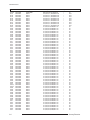
Electrical Part List
Loc.No.
C608
C610
C611
C612
C613
C617
C620
C621
C627
C629
C638
C642
C644
C800
C803
C806
C807
C808
C809
C812
C814
C815
C817
C818
C819
C820
C821
C822
C823
C824
C826
C828
C843
C844
C845
C846
C850
C888
CIS1
CIS1
CIS1
CIS1
CIS1
CIS1
CIS1
CIS3
CN330
CN330
CN330
CN330
CN330
CN330
CN330
CN330
CN909
CR402S
CR403S
CR404S
CR406S
CT501
CT502
CT503
CV101
CV102
CV103
CV104
CV110
CV111A
Code No.
2202-000231
2301-000175
2301-000175
2401-001914
2401-001914
2401-000493
2305-000665
2401-001998
2202-000231
2202-000231
2202-000231
2202-000231
2202-000231
2401-000603
2401-003025
2306-000112
2301-001158
2401-001585
2201-000863
2401-002075
2401-002144
2401-002463
2401-000703
2201-000556
2401-003141
2201-000406
2401-000262
2401-000262
2201-000291
2305-000289
2401-000560
2201-000374
2301-000192
2301-000356
2201-000599
2401-000703
2305-001037
2201-000556
0205-001154
0205-001154
0205-001154
0205-001154
0205-001154
0205-001154
0205-001154
AA40-00016A
3711-001038
3711-001084
3711-003043
3711-004379
3711-002643
3711-002645
3711-002646
3711-002647
AA37-00001A
2306-000330
2306-000327
2301-001065
2301-001091
2401-000832
2401-000832
2305-000665
2306-000122
2401-002463
2202-002037
2305-000665
2301-000383
2202-002253
Samsung Electronics
Description
C-CERAMIC,MLC-AXIAL
C-FILM,LEAD-PEF
C-FILM,LEAD-PEF
C-AL
C-AL
C-AL
C-FILM,LEAD-PEF
C-AL
C-CERAMIC,MLC-AXIAL
C-CERAMIC,MLC-AXIAL
C-CERAMIC,MLC-AXIAL
C-CERAMIC,MLC-AXIAL
C-CERAMIC,MLC-AXIAL
C-AL
C-AL
C-FILM,LEAD-PPF
C-FILM,LEAD-PPF
C-AL
C-CERAMIC,DISC
C-AL
C-AL
C-AL
C-AL
C-CERAMIC,DISC
C-AL
C-CERAMIC,DISC
C-AL
C-AL
C-CERAMIC,DISC
C-FILM,LEAD-PEF
C-AL
C-CERAMIC,DISC
C-FILM,LEAD-PEF
C-FILM,LEAD-PEF
C-CERAMIC,DISC
C-AL
C-FILM,LEAD-PEF
C-CERAMIC,DISC
OIL-SILICON
OIL-SILICON
OIL-SILICON
OIL-SILICON
OIL-SILICON
OIL-SILICON
OIL-SILICON
TUNER
HEADER-BOARD TO CABLE
HEADER-BOARD TO CABLE
HEADER-BOARD TO CABLE
HEADER-BOARD TO CABLE
HEADER-BOARD TO CABLE
HEADER-BOARD TO CABLE
HEADER-BOARD TO CABLE
HEADER-BOARD TO CABLE
CONNECTOR-FBT FIX PIN
C-FILM,LEAD-PPF
C-FILM,LEAD-PPF
C-FILM,LEAD-PPF
C-FILM,LEAD-PPF
C-AL
C-AL
C-FILM,LEAD-PEF
C-FILM,LEAD-PPF
C-AL
C-CERAMIC,MLC-AXIAL
C-FILM,LEAD-PEF
C-FILM,LEAD-PEF
C-CERAMIC,MLC-AXIAL
Specification
0.33NF,10%,50V,Y5P,T
15nF,5%,50V,TP,7.1x3.5x1
15nF,5%,50V,TP,7.1x3.5x1
1uF,20%,50V,BP,TP,5x11,5
1uF,20%,50V,BP,TP,5x11,5
10uF,20%,50V,LZ,TP,5x11mm,5mm
100nF,5%,63V,TP,7.5x4.0x
1000uF,20%,25V,GP,TP,10x20,5mm
0.33NF,10%,50V,Y5P,T
0.33NF,10%,50V,Y5P,T
0.33NF,10%,50V,Y5P,T
0.33NF,10%,50V,Y5P,T
0.33NF,10%,50V,Y5P,T
1UF,20%,50V,GP,TP,5X11,2
330uF,20%,400V,GP,BK,30x40,10
100nF,20%,250V,BK,-,15mm
1nF,5%,800V,TP,15x12x5.5
47uF,20%,50V,WT,TP,8x11.5,5
0.68NF,10%,50V,Y5P,TP,5X3
4.7uF,20%,50V,GP,TP,5x11,5
47uF,20%,16V,GP,TP,5x11,5
470uF,20%,16V,GP,TP,8x11.5,5
2200uF,20%,25V,GP,-,12.5x25mm,
0.47NF,10%,500V,Y5P,TP,5.
2200uF,20%,25V,WT,TP,13x25,5mm
0.27NF,10%,2KV,Y5P,TP,6.3
100uF,20%,160V,HR,TP,16x25,7.5
100uF,20%,160V,HR,TP,16x25,7.5
1NF,10%,500V,Y5P,TP,7.5X3
220nF,5%,63V,TP,-,5mm
1uF,20%,160V,GP,TP,6.3x11,5
0.22NF,5%,50V,C0G,TP,10.5
1nF,5%,50V,TP,5.3x10mm,5
47nF,5%,50V,TP,7.5x4.0x6
0.56NF,10%,500V,Y5P,TP,5.
2200uF,20%,25V,GP,-,12.5x25mm,
330nF,5%,63V,TP,7.5x5.5x
0.47NF,10%,500V,Y5P,TP,5.
G746,-,G746,-,G746,-,G746,-,G746,-,G746,-,G746,-,TDQ-6F/13F2S,NTSC,181CH,45.75MHZ,7
BOX,6P,1R,2.5mm,ST
BOX,8P,1R,2.5MM,ST
BOX,4P,1R,2.5MM,ST
BOX,4P,1R,2mm,STRA
BOX,4P,1R,2.5mm,ST
BOX,6P,1R,2.5mm,ST
BOX,7P,1R,2.5mm,ST
BOX,8P,1R,2.5mm,ST
JM-3500,CPTTV,0.36
7.7NF,3%,1.6KV,BK,28.5X1
6.3nF,3%,1.6KV,TP,28.5x1
47nF,5%,630V,TP,19x15.5x
470nF,5%,400V,BK,26x21.5
220uF,20%,25V,GP,TP,8x11.5,5
220uF,20%,25V,GP,TP,8x11.5,5
100nF,5%,63V,TP,7.5x4.0x
100nF,5%,50V,TP,7.3x4.0x
470uF,20%,16V,GP,TP,8x11.5,5
100nF,80-20%,50V,Y5V
100nF,5%,63V,TP,7.5x4.0x
10nF,5%,50V,TP,6x7x3.2mm
100.0nF,+80-20%,50.0
Q'ty
SA/SNA
1
1
1
1
1
1
1
1
1
1
1
1
1
1
1
1
1
1
1
1
1
1
1
1
1
1
1
1
1
1
1
1
1
1
1
1
1
1
0.1
0.1
0.2
0.1
0.2
0.2
0.2
1
1
1
1
1
1
1
1
1
1
1
1
1
1
1
1
1
1
1
1
1
1
1
S.A
S.A
S.A
S.A
S.A
S.A
S.A
S.A
S.A
S.A
S.A
S.A
S.A
S.A
S.A
S.A
S.A
S.A
S.A
S.A
S.A
S.A
S.A
S.A
S.A
S.A
S.A
S.A
S.A
S.A
S.A
S.A
S.A
S.A
S.A
S.A
S.A
S.A
S.N.A
S.N.A
S.N.A
S.N.A
S.N.A
S.N.A
S.N.A
S.A
S.A
S.A
S.A
S.A
S.A
S.A
S.A
S.A
S.A
S.A
S.A
S.A
S.A
S.A
S.A
S.A
S.A
S.A
S.A
S.A
S.A
S.A
Remark
5-3
Electrical Part List
Loc.No.
CV198
CV199
CV201
CV202
CV203
CV204
CV205
CV206
CV207
CV208
CV209
CV212
CV213
CV214
CV218
CV219
CV222
CV223A
CV231
CV250
CV251
CV252
CV253
CV254
CV255
CV256
CV257
CV258
CV259
CV260
CV261
CV262B
CV271
CV272
CV601
CV602
CV603
CV604
CV605
CV606
CV607
CV608
CV611
CV612
CV643
CV701
CV702
CV703
CV704
CV705
CV901
CV902
CV903
CV904
CV905
CV907
CV908
CV909
CV910
CV911
CV912
CV913
CV914
CV915
CV918
CV920
CV933
CV934
5-4
Code No.
2202-000216
2202-000216
2202-000796
2401-002619
2202-000796
2401-002619
2202-000796
2401-002619
2202-000796
2202-000796
2202-000796
2305-000665
2305-000665
2401-002075
2401-002619
2202-000796
2401-000603
2301-001211
2401-002619
2202-000632
2202-000632
2202-000632
2201-000389
2201-000389
2401-002619
2202-000796
2202-000796
2401-002619
2202-000796
2305-000665
2401-002619
2202-000796
2202-000243
2401-000025
2202-002037
2401-001026
2401-001989
2401-001989
2401-001989
2401-001989
2401-001989
2401-001989
2401-002619
2202-000796
2202-000231
2202-000231
2202-000231
2202-000243
2202-000243
2202-000243
2401-000603
2202-000796
2401-002075
2202-000796
2401-002619
2401-002619
2202-000796
2401-002619
2305-000412
2305-000412
2202-002037
2202-000121
2202-002037
2202-000121
2401-003578
2202-000863
2305-000411
2305-000411
Description
C-CERAMIC,MLC-AXIAL
C-CERAMIC,MLC-AXIAL
C-CERAMIC,MLC-AXIAL
C-AL
C-CERAMIC,MLC-AXIAL
C-AL
C-CERAMIC,MLC-AXIAL
C-AL
C-CERAMIC,MLC-AXIAL
C-CERAMIC,MLC-AXIAL
C-CERAMIC,MLC-AXIAL
C-FILM,LEAD-PEF
C-FILM,LEAD-PEF
C-AL
C-AL
C-CERAMIC,MLC-AXIAL
C-AL
C-FILM,LEAD-PPF
C-AL
C-CERAMIC,MLC-AXIAL
C-CERAMIC,MLC-AXIAL
C-CERAMIC,MLC-AXIAL
C-CERAMIC,DISC
C-CERAMIC,DISC
C-AL
C-CERAMIC,MLC-AXIAL
C-CERAMIC,MLC-AXIAL
C-AL
C-CERAMIC,MLC-AXIAL
C-FILM,LEAD-PEF
C-AL
C-CERAMIC,MLC-AXIAL
C-CERAMIC,MLC-AXIAL
C-AL
C-CERAMIC,MLC-AXIAL
C-AL
C-AL
C-AL
C-AL
C-AL
C-AL
C-AL
C-AL
C-CERAMIC,MLC-AXIAL
C-CERAMIC,MLC-AXIAL
C-CERAMIC,MLC-AXIAL
C-CERAMIC,MLC-AXIAL
C-CERAMIC,MLC-AXIAL
C-CERAMIC,MLC-AXIAL
C-CERAMIC,MLC-AXIAL
C-AL
C-CERAMIC,MLC-AXIAL
C-AL
C-CERAMIC,MLC-AXIAL
C-AL
C-AL
C-CERAMIC,MLC-AXIAL
C-AL
C-FILM,LEAD-PEF
C-FILM,LEAD-PEF
C-CERAMIC,MLC-AXIAL
C-CERAMIC,MLC-AXIAL
C-CERAMIC,MLC-AXIAL
C-CERAMIC,MLC-AXIAL
C-AL
C-CERAMIC,MLC-AXIAL
C-FILM,LEAD-PEF
C-FILM,LEAD-PEF
Specification
0.027NF,5%,50V,SL,TP
0.027NF,5%,50V,SL,TP
1NF,10%,50V,Y5P,TP,3
47uF,20%,25V,GP,TP,5x11,5
1NF,10%,50V,Y5P,TP,3
47uF,20%,25V,GP,TP,5x11,5
1NF,10%,50V,Y5P,TP,3
47uF,20%,25V,GP,TP,5x11,5
1NF,10%,50V,Y5P,TP,3
1NF,10%,50V,Y5P,TP,3
1NF,10%,50V,Y5P,TP,3
100nF,5%,63V,TP,7.5x4.0x
100nF,5%,63V,TP,7.5x4.0x
4.7uF,20%,50V,GP,TP,5x11,5
47uF,20%,25V,GP,TP,5x11,5
1NF,10%,50V,Y5P,TP,3
1UF,20%,50V,GP,TP,5X11,2
22nF,5%,400V,TP,20x7x14m
47uF,20%,25V,GP,TP,5x11,5
100nF,20%,50V,Z5U,TP
100nF,20%,50V,Z5U,TP
100nF,20%,50V,Z5U,TP
0.022NF,5%,50V,C0G,TP,5X3
0.022NF,5%,50V,C0G,TP,5X3
47uF,20%,25V,GP,TP,5x11,5
1NF,10%,50V,Y5P,TP,3
1NF,10%,50V,Y5P,TP,3
47uF,20%,25V,GP,TP,5x11,5
1NF,10%,50V,Y5P,TP,3
100nF,5%,63V,TP,7.5x4.0x
47uF,20%,25V,GP,TP,5x11,5
1NF,10%,50V,Y5P,TP,3
33pF,5%,50V,SL,TP,3.
100uF,20%,16V,GP,TP,6.3x11,5
100nF,80-20%,50V,Y5V
3.3UF,20%,50V,GP,TP,5X11,5
4.7uF,20%,50V,BP,TP,5x11,5
4.7uF,20%,50V,BP,TP,5x11,5
4.7uF,20%,50V,BP,TP,5x11,5
4.7uF,20%,50V,BP,TP,5x11,5
4.7uF,20%,50V,BP,TP,5x11,5
4.7uF,20%,50V,BP,TP,5x11,5
47uF,20%,25V,GP,TP,5x11,5
1NF,10%,50V,Y5P,TP,3
0.33NF,10%,50V,Y5P,T
0.33NF,10%,50V,Y5P,T
0.33NF,10%,50V,Y5P,T
33pF,5%,50V,SL,TP,3.
33pF,5%,50V,SL,TP,3.
33pF,5%,50V,SL,TP,3.
1UF,20%,50V,GP,TP,5X11,2
1NF,10%,50V,Y5P,TP,3
4.7uF,20%,50V,GP,TP,5x11,5
1NF,10%,50V,Y5P,TP,3
47uF,20%,25V,GP,TP,5x11,5
47uF,20%,25V,GP,TP,5x11,5
1NF,10%,50V,Y5P,TP,3
47uF,20%,25V,GP,TP,5x11,5
470nF,5%,63V,TP,-,5mm
470nF,5%,63V,TP,-,5mm
100nF,80-20%,50V,Y5V
0.1nF,10%,50V,Y5P,-,
100nF,80-20%,50V,Y5V
0.1nF,10%,50V,Y5P,-,
1000uF,20%,10V,GP,TP,8x20mm,5
560pF,10%,50V,Y5P,TP
470nF,5%,50V,TP,7.3x4.8x
470nF,5%,50V,TP,7.3x4.8x
Q'ty
SA/SNA
1
1
1
1
1
1
1
1
1
1
1
1
1
1
1
1
1
1
1
1
1
1
1
1
1
1
1
1
1
1
1
1
1
1
1
1
1
1
1
1
1
1
1
1
1
1
1
1
1
1
1
1
1
1
1
1
1
1
1
1
1
1
1
1
1
1
1
1
S.A
S.A
S.A
S.A
S.A
S.A
S.A
S.A
S.A
S.A
S.A
S.A
S.A
S.A
S.A
S.A
S.A
S.A
S.A
S.A
S.A
S.A
S.A
S.A
S.A
S.A
S.A
S.A
S.A
S.A
S.A
S.A
S.A
S.A
S.A
S.A
S.A
S.A
S.A
S.A
S.A
S.A
S.A
S.A
S.A
S.A
S.A
S.A
S.A
S.A
S.A
S.A
S.A
S.A
S.A
S.A
S.A
S.A
S.A
S.A
S.A
S.A
S.A
S.A
S.A
S.A
S.A
S.A
Remark
Samsung Electronics
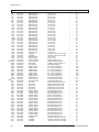
Electrical Part List
Loc.No.
CV935
CX801S
CY801S
CY802S
D0254
D303
D402
D403
D404
D405
D406
D407
D408
D409
D499
D800S
D803
D804
D805
D806
D807
D808
D809A
D811
D813
D814
D818
D819
D823
D824
D825
D901
DU410
DV201
DV202
DV203
DV901
DV951
DV952
DZ201
DZ242
DZ299
DZ301
DZ302
DZ303
DZ306
DZ603
DZ701
DZ702
DZ703
DZ704
DZ802
DZ807
DZ810
DZ811
DZ812
DZ813
DZ814
DZ815
DZ816
DZ820
DZ821
DZ905
DZV101
DZV200
DZV201
DZV203
DZV205
Code No.
2305-000411
2306-000321
2201-000963
2201-000987
0404-001056
0402-000546
0402-000132
0402-000132
0402-001599
0402-000534
0402-000540
0402-000540
0402-001295
0401-000005
0401-000005
0402-000116
0402-000546
0401-000006
0401-000006
0402-000546
0402-001604
0402-000132
0402-001604
0402-001603
0402-000493
0401-000005
0403-000714
0401-000005
0402-000132
0403-000720
0403-000720
0401-000005
1201-000010
0401-000005
0401-000005
0401-000005
0401-000005
0401-000005
0401-000005
0403-000508
0403-000510
0403-000508
0403-001329
0403-001329
0403-001221
0403-000700
0403-000720
0403-000720
0403-000720
0403-000720
0403-000720
0403-000509
0403-000718
0403-000509
0403-000700
0403-000700
0403-000720
0403-001320
0403-001321
0401-000005
0403-001373
0401-000005
0403-001317
0403-000508
0403-000508
0403-000714
0403-001320
0403-000720
Samsung Electronics
Description
C-FILM,LEAD-PEF
C-FILM,LEAD-PPF
C-CERAMIC,DISC
C-CERAMIC,DISC
DIODE-SCHOTTKY
DIODE-RECTIFIER
DIODE-RECTIFIER
DIODE-RECTIFIER
DIODE-RECTIFIER
DIODE-RECTIFIER
DIODE-RECTIFIER
DIODE-RECTIFIER
DIODE-RECTIFIER
DIODE-SWITCHING
DIODE-SWITCHING
DIODE-BRIDGE
DIODE-RECTIFIER
DIODE-SWITCHING
DIODE-SWITCHING
DIODE-RECTIFIER
DIODE-RECTIFIER
DIODE-RECTIFIER
DIODE-RECTIFIER
DIODE-RECTIFIER
DIODE-RECTIFIER
DIODE-SWITCHING
DIODE-ZENER
DIODE-SWITCHING
DIODE-RECTIFIER
DIODE-ZENER
DIODE-ZENER
DIODE-SWITCHING
IC-OP AMP
DIODE-SWITCHING
DIODE-SWITCHING
DIODE-SWITCHING
DIODE-SWITCHING
DIODE-SWITCHING
DIODE-SWITCHING
DIODE-ZENER
DIODE-ZENER
DIODE-ZENER
DIODE-ZENER
DIODE-ZENER
DIODE-ZENER
DIODE-ZENER
DIODE-ZENER
DIODE-ZENER
DIODE-ZENER
DIODE-ZENER
DIODE-ZENER
DIODE-ZENER
DIODE-ZENER
DIODE-ZENER
DIODE-ZENER
DIODE-ZENER
DIODE-ZENER
DIODE-ZENER
DIODE-ZENER
DIODE-SWITCHING
DIODE-ZENER
DIODE-SWITCHING
DIODE-ZENER
DIODE-ZENER
DIODE-ZENER
DIODE-ZENER
DIODE-ZENER
DIODE-ZENER
Specification
470nF,5%,50V,TP,7.3x4.8x
470NF,20%,275V,BK,31X11X
1NF,20%,400V,Y5U,TP,9.5X6
2.2NF,20%,400V,Y5U,BK,12.
RK16,60V,1500MA,DO-204AC,
TVR10G,400V,1A,DO-41,TP
1N4004,400V,1A,DO-41,TP
1N4004,400V,1A,DO-41,TP
DGP30L,1500,3A,DO-201AD(
RG10V,400V,1.2A,DO-201,T
RU20A,600V,1.5A,-,TP
RU20A,600V,1.5A,-,TP
GUR460L-5700,600V,4A,DO1N4148,75V,150mA,DO-35,T
1N4148,75V,150mA,DO-35,T
RBV606,600V,6A,SIP-4,ST
TVR10G,400V,1A,DO-41,TP
BAV21,250V,200mA,DO-35,T
BAV21,250V,200mA,DO-35,T
TVR10G,400V,1A,DO-41,TP
MUR420,200V,4A,DO-201AD,
1N4004,400V,1A,DO-41,TP
MUR420,200V,4A,DO-201AD,
MUR480E,800V,4A,DO-201AD
1R5GU41,400V,1.5A,DO-15L
1N4148,75V,150mA,DO-35,T
MTZJ3.3B,3.32-3.53V,500mW,DO
1N4148,75V,150mA,DO-35,T
1N4004,400V,1A,DO-41,TP
MTZJ9.1B,8.57-9.01V,500mW,DO
MTZJ9.1B,8.57-9.01V,500mW,DO
1N4148,75V,150mA,DO-35,T
2030,PENTAWATT,5P,-,SINGLE,-,C
1N4148,75V,150mA,DO-35,T
1N4148,75V,150mA,DO-35,T
1N4148,75V,150mA,DO-35,T
1N4148,75V,150mA,DO-35,T
1N4148,75V,150mA,DO-35,T
1N4148,75V,150mA,DO-35,T
MTZJ5.6B,5.45-5.73V,500mW,DO
MTZJ6.2B,5.96-6.27V,500mW,DO
MTZJ5.6B,5.45-5.73V,500mW,DO
MTZJ24B,22.75-23.73V,500mW,D
MTZJ24B,22.75-23.73V,500mW,D
UZ39BSB,35.36-37.19V,500mW,D
TZP33A,5%,1000mW,DO-41,TP
MTZJ9.1B,8.57-9.01V,500mW,DO
MTZJ9.1B,8.57-9.01V,500mW,DO
MTZJ9.1B,8.57-9.01V,500mW,DO
MTZJ9.1B,8.57-9.01V,500mW,DO
MTZJ9.1B,8.57-9.01V,500mW,DO
MTZJ5.6B,5.4-5.7V,500mW,DO-3
MTZJ6.8B,6.52-6.79V,500mW,DO
MTZJ5.6B,5.4-5.7V,500mW,DO-3
TZP33A,5%,1000mW,DO-41,TP
TZP33A,5%,1000mW,DO-41,TP
MTZJ9.1B,8.57-9.01V,500mW,DO
MTZJ6.2C,6.16-6.4V,500mW,DOMTZJ6.8C,6.7-6.97V,500mW,DO1N4148,75V,150mA,DO-35,T
MTZJ5.1A,4.85-5.03V,500mW,DO
1N4148,75V,150mA,DO-35,T
MTZJ3.0B,3.01-3.22V,500mW,DO
MTZJ5.6B,5.45-5.73V,500mW,DO
MTZJ5.6B,5.45-5.73V,500mW,DO
MTZJ3.3B,3.32-3.53V,500mW,DO
MTZJ6.2C,6.16-6.4V,500mW,DOMTZJ9.1B,8.57-9.01V,500mW,DO
Q'ty
SA/SNA
1
1
1
1
1
1
1
1
1
1
1
1
1
1
1
1
1
1
1
1
1
1
1
1
1
1
1
1
1
1
1
1
1
1
1
1
1
1
1
1
1
1
1
1
1
1
1
1
1
1
1
1
1
1
1
1
1
1
1
1
1
1
1
1
1
1
1
1
S.A
S.A
S.A
S.A
S.A
S.A
S.A
S.A
S.A
S.A
S.A
S.A
S.A
S.A
S.A
S.A
S.A
S.A
S.A
S.A
S.A
S.A
S.A
S.A
S.A
S.A
S.A
S.A
S.A
S.A
S.A
S.A
S.A
S.A
S.A
S.A
S.A
S.A
S.A
S.A
S.A
S.A
S.A
S.A
S.A
S.A
S.A
S.A
S.A
S.A
S.A
S.A
S.A
S.A
S.A
S.A
S.A
S.A
S.A
S.A
S.A
S.A
S.A
S.A
S.A
S.A
S.A
S.A
Remark
5-5
Electrical Part List
Loc.No.
DZV902
EL401
EL402
EL403
EL404
EL407
EL408
EL801
EL802
EL803
EY401
EY402
EY403
EY404
EY405
EY406
EY407
EY408
EY409
EY410
EY411
EY412
EY413
EY414
EY415
EY416
EY417
EY418
EY419
EY420
EY421
EY422
EY423
EY424
EY425
EY426
EY427
EY428
EY429
EY430
EY431
EY432
EY433
EY434
EY435
EY601
EY602
EY603
EY604
EY801
EY8018
EY8019
EY802
EY803
EY804
EY805
EY806
EY807
EY808
EY809
EY810
EY811
EY812
EY813
EY814
EY815
EY816
EY817
5-6
Code No.
0403-000508
6042-000001
6042-000001
6042-000001
6042-000001
6042-000001
6042-000001
6042-000001
6042-000001
6042-000001
6042-000002
6042-000002
6042-000002
6042-000002
6042-000002
6042-000002
6042-000002
6042-000002
6042-000002
6042-000002
6042-000002
6042-000002
6042-000002
6042-000002
6042-000002
6042-000002
6042-000002
6042-000002
6042-000002
6042-000002
6042-000002
6042-000002
6042-000002
6042-000002
6042-000002
6042-000002
6042-000002
6042-000002
6042-000002
6042-000002
6042-000002
6042-000002
6042-000002
6042-000002
6042-000002
6042-000002
6042-000002
6042-000002
6042-000002
6042-000002
6042-000002
6042-000002
6042-000002
6042-000002
6042-000002
6042-000002
6042-000002
6042-000002
6042-000002
6042-000002
6042-000002
6042-000002
6042-000002
6042-000002
6042-000002
6042-000002
6042-000002
6042-000002
Description
DIODE-ZENER
EYELET
EYELET
EYELET
EYELET
EYELET
EYELET
EYELET
EYELET
EYELET
EYELET
EYELET
EYELET
EYELET
EYELET
EYELET
EYELET
EYELET
EYELET
EYELET
EYELET
EYELET
EYELET
EYELET
EYELET
EYELET
EYELET
EYELET
EYELET
EYELET
EYELET
EYELET
EYELET
EYELET
EYELET
EYELET
EYELET
EYELET
EYELET
EYELET
EYELET
EYELET
EYELET
EYELET
EYELET
EYELET
EYELET
EYELET
EYELET
EYELET
EYELET
EYELET
EYELET
EYELET
EYELET
EYELET
EYELET
EYELET
EYELET
EYELET
EYELET
EYELET
EYELET
EYELET
EYELET
EYELET
EYELET
EYELET
Specification
MTZJ5.6B,5.45-5.73V,500mW,DO
ID2.2,OD2.7,L3.1,NI+SN,BSP3-1/2H
ID2.2,OD2.7,L3.1,NI+SN,BSP3-1/2H
ID2.2,OD2.7,L3.1,NI+SN,BSP3-1/2H
ID2.2,OD2.7,L3.1,NI+SN,BSP3-1/2H
ID2.2,OD2.7,L3.1,NI+SN,BSP3-1/2H
ID2.2,OD2.7,L3.1,NI+SN,BSP3-1/2H
ID2.2,OD2.7,L3.1,NI+SN,BSP3-1/2H
ID2.2,OD2.7,L3.1,NI+SN,BSP3-1/2H
ID2.2,OD2.7,L3.1,NI+SN,BSP3-1/2H
ID1.5,OD2,L2.8,NI+SN,BSP3-1/2H
ID1.5,OD2,L2.8,NI+SN,BSP3-1/2H
ID1.5,OD2,L2.8,NI+SN,BSP3-1/2H
ID1.5,OD2,L2.8,NI+SN,BSP3-1/2H
ID1.5,OD2,L2.8,NI+SN,BSP3-1/2H
ID1.5,OD2,L2.8,NI+SN,BSP3-1/2H
ID1.5,OD2,L2.8,NI+SN,BSP3-1/2H
ID1.5,OD2,L2.8,NI+SN,BSP3-1/2H
ID1.5,OD2,L2.8,NI+SN,BSP3-1/2H
ID1.5,OD2,L2.8,NI+SN,BSP3-1/2H
ID1.5,OD2,L2.8,NI+SN,BSP3-1/2H
ID1.5,OD2,L2.8,NI+SN,BSP3-1/2H
ID1.5,OD2,L2.8,NI+SN,BSP3-1/2H
ID1.5,OD2,L2.8,NI+SN,BSP3-1/2H
ID1.5,OD2,L2.8,NI+SN,BSP3-1/2H
ID1.5,OD2,L2.8,NI+SN,BSP3-1/2H
ID1.5,OD2,L2.8,NI+SN,BSP3-1/2H
ID1.5,OD2,L2.8,NI+SN,BSP3-1/2H
ID1.5,OD2,L2.8,NI+SN,BSP3-1/2H
ID1.5,OD2,L2.8,NI+SN,BSP3-1/2H
ID1.5,OD2,L2.8,NI+SN,BSP3-1/2H
ID1.5,OD2,L2.8,NI+SN,BSP3-1/2H
ID1.5,OD2,L2.8,NI+SN,BSP3-1/2H
ID1.5,OD2,L2.8,NI+SN,BSP3-1/2H
ID1.5,OD2,L2.8,NI+SN,BSP3-1/2H
ID1.5,OD2,L2.8,NI+SN,BSP3-1/2H
ID1.5,OD2,L2.8,NI+SN,BSP3-1/2H
ID1.5,OD2,L2.8,NI+SN,BSP3-1/2H
ID1.5,OD2,L2.8,NI+SN,BSP3-1/2H
ID1.5,OD2,L2.8,NI+SN,BSP3-1/2H
ID1.5,OD2,L2.8,NI+SN,BSP3-1/2H
ID1.5,OD2,L2.8,NI+SN,BSP3-1/2H
ID1.5,OD2,L2.8,NI+SN,BSP3-1/2H
ID1.5,OD2,L2.8,NI+SN,BSP3-1/2H
ID1.5,OD2,L2.8,NI+SN,BSP3-1/2H
ID1.5,OD2,L2.8,NI+SN,BSP3-1/2H
ID1.5,OD2,L2.8,NI+SN,BSP3-1/2H
ID1.5,OD2,L2.8,NI+SN,BSP3-1/2H
ID1.5,OD2,L2.8,NI+SN,BSP3-1/2H
ID1.5,OD2,L2.8,NI+SN,BSP3-1/2H
ID1.5,OD2,L2.8,NI+SN,BSP3-1/2H
ID1.5,OD2,L2.8,NI+SN,BSP3-1/2H
ID1.5,OD2,L2.8,NI+SN,BSP3-1/2H
ID1.5,OD2,L2.8,NI+SN,BSP3-1/2H
ID1.5,OD2,L2.8,NI+SN,BSP3-1/2H
ID1.5,OD2,L2.8,NI+SN,BSP3-1/2H
ID1.5,OD2,L2.8,NI+SN,BSP3-1/2H
ID1.5,OD2,L2.8,NI+SN,BSP3-1/2H
ID1.5,OD2,L2.8,NI+SN,BSP3-1/2H
ID1.5,OD2,L2.8,NI+SN,BSP3-1/2H
ID1.5,OD2,L2.8,NI+SN,BSP3-1/2H
ID1.5,OD2,L2.8,NI+SN,BSP3-1/2H
ID1.5,OD2,L2.8,NI+SN,BSP3-1/2H
ID1.5,OD2,L2.8,NI+SN,BSP3-1/2H
ID1.5,OD2,L2.8,NI+SN,BSP3-1/2H
ID1.5,OD2,L2.8,NI+SN,BSP3-1/2H
ID1.5,OD2,L2.8,NI+SN,BSP3-1/2H
ID1.5,OD2,L2.8,NI+SN,BSP3-1/2H
Q'ty
1
1
1
1
1
1
1
1
1
1
1
1
1
1
1
1
1
1
1
1
1
1
1
1
1
1
1
1
1
1
1
1
1
1
1
1
1
1
1
1
1
1
1
1
1
1
1
1
1
1
1
1
1
1
1
1
1
1
1
1
1
1
1
1
1
1
1
1
SA/SNA
Remark
S.A
S.N.A
S.N.A
S.N.A
S.N.A
S.N.A
S.N.A
S.N.A
S.N.A
S.N.A
S.A
S.A
S.A
S.A
S.A
S.A
S.A
S.A
S.A
S.A
S.A
S.A
S.A
S.A
S.A
S.A
S.A
S.A
S.A
S.A
S.A
S.A
S.A
S.A
S.A
S.A
S.A
S.A
S.A
S.A
S.A
S.A
S.A
S.A
S.A
S.A
S.A
S.A
S.A
S.A
S.A
S.A
S.A
S.A
S.A
S.A
S.A
S.A
S.A
S.A
S.A
S.A
S.A
S.A
S.A
S.A
S.A
S.A
Samsung Electronics
Electrical Part List
Loc.No.
EY818
EY819
EY820
EY821
EY822
EY823
EY824
EY825
EY826
EY827
EY828
EY829
EY830
EY831
EY832
EY833
EY834
EY835
EY836
EY837
EY838
EY839
EY840
F101
F101
F101
F101
F801A
F801B
FD801A
FD802
FD802S
GT301
GT404
GT801
GT804
GT805
GT806
GTT01
GTT02
H/S
IC012
IC063
IC112
IC202
IC301
IC602
IC801S
IC804
ICT501
ICV101
ICV201
L104
L106
L2514
L2514
L2514
L2514
L2514
L2514
L2514
L2514
L2514
L2514
L2514
L406
L424
L605
Code No.
6042-000002
6042-000002
6042-000002
6042-000002
6042-000002
6042-000002
6042-000002
6042-000002
6042-000002
6042-000002
6042-000002
6042-000002
6042-000002
6042-000002
6042-000002
6042-000002
6042-000002
6042-000002
6042-000002
6042-000002
6042-000002
6042-000002
6042-000002
2901-000297
2901-000297
2901-000297
2901-000297
3602-000114
3602-000114
3601-001228
3601-000297
3601-001163
AA60-40012F
BH71-40300A
AA60-40012G
BH71-40300A
BH71-40300A
BH71-40300A
BH71-40300A
BH71-40300A
AA61-01390A
1203-001217
AA13-00114A
1103-001171
1203-001943
AA96-00623F
BP96-00418B
AA96-50371S
AA96-00243K
BH99-00007T
2904-001196
AA09-00463B
2701-000116
2701-000114
3301-000287
3301-000287
3301-000287
3301-000287
3301-000287
3301-000287
3301-000287
3301-000287
3301-000287
3301-000287
3301-000287
2004-001402
2701-000142
2701-000114
Samsung Electronics
Description
EYELET
EYELET
EYELET
EYELET
EYELET
EYELET
EYELET
EYELET
EYELET
EYELET
EYELET
EYELET
EYELET
EYELET
EYELET
EYELET
EYELET
EYELET
EYELET
EYELET
EYELET
EYELET
EYELET
FILTER-EMI ON BOARD
FILTER-EMI ON BOARD
FILTER-EMI ON BOARD
FILTER-EMI ON BOARD
FUSE-HOLDER
FUSE-HOLDER
FUSE-AXIAL LEAD
FUSE-CARTRIDGE
FUSE-AXIAL LEAD
PIN-GT
PIN-HINGE
PIN-GT
PIN-HINGE
PIN-HINGE
PIN-HINGE
PIN-HINGE
PIN-HINGE
BRACKET
IC-POSI.ADJUST REG.
IC HYBRID
IC-EEPROM
IC-VOL. DETECTOR
ASSY HEAT SINK P
ASSY HEAT SINK P
ASSY HEAT SINK P
ASSY HEAT SINK P
ASSY HEAT/SINK
FILTER-SAW AV
IC MICOM MTP
INDUCTOR-AXIAL
INDUCTOR-AXIAL
BEAD-AXIAL
BEAD-AXIAL
BEAD-AXIAL
BEAD-AXIAL
BEAD-AXIAL
BEAD-AXIAL
BEAD-AXIAL
BEAD-AXIAL
BEAD-AXIAL
BEAD-AXIAL
BEAD-AXIAL
R-METAL(S)
INDUCTOR-AXIAL
INDUCTOR-AXIAL
Specification
ID1.5,OD2,L2.8,NI+SN,BSP3-1/2H
ID1.5,OD2,L2.8,NI+SN,BSP3-1/2H
ID1.5,OD2,L2.8,NI+SN,BSP3-1/2H
ID1.5,OD2,L2.8,NI+SN,BSP3-1/2H
ID1.5,OD2,L2.8,NI+SN,BSP3-1/2H
ID1.5,OD2,L2.8,NI+SN,BSP3-1/2H
ID1.5,OD2,L2.8,NI+SN,BSP3-1/2H
ID1.5,OD2,L2.8,NI+SN,BSP3-1/2H
ID1.5,OD2,L2.8,NI+SN,BSP3-1/2H
ID1.5,OD2,L2.8,NI+SN,BSP3-1/2H
ID1.5,OD2,L2.8,NI+SN,BSP3-1/2H
ID1.5,OD2,L2.8,NI+SN,BSP3-1/2H
ID1.5,OD2,L2.8,NI+SN,BSP3-1/2H
ID1.5,OD2,L2.8,NI+SN,BSP3-1/2H
ID1.5,OD2,L2.8,NI+SN,BSP3-1/2H
ID1.5,OD2,L2.8,NI+SN,BSP3-1/2H
ID1.5,OD2,L2.8,NI+SN,BSP3-1/2H
ID1.5,OD2,L2.8,NI+SN,BSP3-1/2H
ID1.5,OD2,L2.8,NI+SN,BSP3-1/2H
ID1.5,OD2,L2.8,NI+SN,BSP3-1/2H
ID1.5,OD2,L2.8,NI+SN,BSP3-1/2H
ID1.5,OD2,L2.8,NI+SN,BSP3-1/2H
ID1.5,OD2,L2.8,NI+SN,BSP3-1/2H
-,3A,-,3.5x5mm,TP,-,3A,-,3.5x5mm,TP,-,3A,-,3.5x5mm,TP,-,3A,-,3.5x5mm,TP,-,-,30mohm
-,-,30mohm
125V,10A,FAST-ACTING,EPO
250V,5A,TIME-LAG,GLASS,5.
125V,7A,-,EPOXY,2.4X7.1M
4P,2.36PI,6/12/14mm,NYLON66,LOCKI
BRASS,D2.36!,HEAT/SINK,SN
3P,2.36PI,10/5mm,NYLON66,LOCKING
BRASS,D2.36!,HEAT/SINK,SN
BRASS,D2.36!,HEAT/SINK,SN
BRASS,D2.36!,HEAT/SINK,SN
BRASS,D2.36!,HEAT/SINK,SN
BRASS,D2.36!,HEAT/SINK,SN
CT-29A20HR,SECC,T1.0
431,TO-92,3P,4.58MIL
STR-X6750F,EMPEROR,7,-20~+125,
24C161,2Kx8,DIP,8P,9.2x6.4mm,2
7025,TO-92,3P,-,PLASTIC
LA78045,SCREW,AA62-0005
AA62-30182F,SCREW,TDA72
AA62-30181H,SCREW,STR-X
-,REGULATOR,AA62-000450
BH62-00007A,SCREW,TDA2030
44MHZ,SIP5K,ST,16.2DB,-,42
VCT4822,VCT49X3F-PY,F1,CT-2
10UH,10%,4298
10UH,10%,2534
,3.5x1.0x6.0mm,3000mA,TP,,,50
,3.5x1.0x6.0mm,3000mA,TP,,,50
,3.5x1.0x6.0mm,3000mA,TP,,,50
,3.5x1.0x6.0mm,3000mA,TP,,,50
,3.5x1.0x6.0mm,3000mA,TP,,,50
,3.5x1.0x6.0mm,3000mA,TP,,,50
,3.5x1.0x6.0mm,3000mA,TP,,,50
,3.5x1.0x6.0mm,3000mA,TP,,,50
,3.5x1.0x6.0mm,3000mA,TP,,,50
,3.5x1.0x6.0mm,3000mA,TP,,,50
,3.5x1.0x6.0mm,3000mA,TP,,,50
6.8Kohm,1%,1/2W,AA,TP,2.4x6.4
1UH,10%,2534
10UH,10%,2534
Q'ty
1
1
1
1
1
1
1
1
1
1
1
1
1
1
1
1
1
1
1
1
1
1
1
1
1
1
1
1
1
1
1
1
1
1
1
1
1
1
1
1
1
1
1
1
1
1
1
1
1
1
1
1
1
1
1
1
1
1
1
1
1
1
1
1
1
1
1
1
SA/SNA
Remark
S.A
S.A
S.A
S.A
S.A
S.A
S.A
S.A
S.A
S.A
S.A
S.A
S.A
S.A
S.A
S.A
S.A
S.A
S.A
S.A
S.A
S.A
S.A
S.A
S.A
S.A
S.A
S.A
S.A
S.A
S.A
S.A
S.N.A
S.N.A
S.N.A
S.N.A
S.N.A
S.N.A
S.N.A
S.N.A
S.N.A
S.A
S.A
S.A
S.A
S.N.A
S.N.A
S.N.A
S.N.A
S.N.A
S.A
S.N.A
S.A
S.A
S.N.A
S.N.A
S.N.A
S.N.A
S.N.A
S.N.A
S.N.A
S.N.A
S.N.A
S.N.A
S.N.A
S.A
S.A
S.A
5-7
Electrical Part List
Loc.No.
L606
L607
L608
L705
L706
L808
L825
LV101
LV201
LV202
LV203
LV204
LV205
LV206
LV251
LV252A
LV252B
LV253
LV601
LV701
LV702
LV703
LV704
LV705
LV901
LV902
LV903
LV904
LV905
LX801S
M0014
M0018
M0020
M0081
M0081
M0081
M0081
M0081
M0081
M0081
P803T
PC801S
Q401
Q403
Q409
Q409
Q409
Q409
Q802
Q805
Q806
Q811
Q814
QE02
QV202
QV203
QV204
QV205
QV207
QV272
QV273
QV901
QV902
QV905
QV951
R104
R107
R205
5-8
Code No.
2701-000114
2701-000177
2701-000177
2701-000177
2701-000177
2701-001030
2701-000142
2701-000114
2701-000143
2701-000143
2701-000143
2701-000115
2701-000159
2701-000184
2701-000116
2701-000114
2701-000114
2702-001094
2701-000115
2701-000142
2701-000142
2701-000142
2701-000168
2701-000168
2701-000143
2001-000281
2001-000281
2701-000116
2701-000158
AA29-00011A
AA97-16528B
AA97-16687A
AA96-04061A
6003-000335
6003-000334
6003-000334
6003-000334
6003-000335
6003-000333
6003-000333
1404-001264
0604-001032
AA96-00624A
0502-001007
0505-001723
0505-000109
0505-000109
0505-000109
0501-000389
0501-000389
0501-000389
0501-000369
0501-000369
AA96-00624G
0501-000389
0501-000283
0501-000283
0501-000283
0501-000010
0501-000283
0501-000389
0501-000389
0501-000389
0501-000010
0501-000389
2001-000281
2001-000281
2001-000613
Description
INDUCTOR-AXIAL
INDUCTOR-AXIAL
INDUCTOR-AXIAL
INDUCTOR-AXIAL
INDUCTOR-AXIAL
INDUCTOR-AXIAL
INDUCTOR-AXIAL
INDUCTOR-AXIAL
INDUCTOR-AXIAL
INDUCTOR-AXIAL
INDUCTOR-AXIAL
INDUCTOR-AXIAL
INDUCTOR-AXIAL
INDUCTOR-AXIAL
INDUCTOR-AXIAL
INDUCTOR-AXIAL
INDUCTOR-AXIAL
INDUCTOR-RADIAL
INDUCTOR-AXIAL
INDUCTOR-AXIAL
INDUCTOR-AXIAL
INDUCTOR-AXIAL
INDUCTOR-AXIAL
INDUCTOR-AXIAL
INDUCTOR-AXIAL
R-CARBON
R-CARBON
INDUCTOR-AXIAL
INDUCTOR-AXIAL
FILTER LINE NOISE
ASSY AUTO-MAIN
ASSY MICOM
ASSY BOARD P
SCREW-TAPTITE
SCREW-TAPTITE
SCREW-TAPTITE
SCREW-TAPTITE
SCREW-TAPTITE
SCREW-TAPTITE
SCREW-TAPTITE
THERMISTOR-PTC
PHOTO-COUPLER
ASSY HEAT SINK P
TR-POWER
FET-SILICON
FET-SILICON
FET-SILICON
FET-SILICON
TR-SMALL SIGNAL
TR-SMALL SIGNAL
TR-SMALL SIGNAL
TR-SMALL SIGNAL
TR-SMALL SIGNAL
ASSY HEAT SINK P
TR-SMALL SIGNAL
TR-SMALL SIGNAL
TR-SMALL SIGNAL
TR-SMALL SIGNAL
TR-SMALL SIGNAL
TR-SMALL SIGNAL
TR-SMALL SIGNAL
TR-SMALL SIGNAL
TR-SMALL SIGNAL
TR-SMALL SIGNAL
TR-SMALL SIGNAL
R-CARBON
R-CARBON
R-CARBON
Specification
10UH,10%,2534
33UH,10%,2534
33UH,10%,2534
33UH,10%,2534
33UH,10%,2534
43UH,10%,4514
1UH,10%,2534
10UH,10%,2534
1UH,10%,3070
1UH,10%,3070
1UH,10%,3070
10UH,10%,3070
22UH,10%,4298
4.7UH,10%,2534
10UH,10%,4298
10UH,10%,2534
10UH,10%,2534
10uH,10%,4x6mm
10UH,10%,3070
1UH,10%,2534
1UH,10%,2534
1UH,10%,2534
3.3UH,5%,2534
3.3UH,5%,2534
1UH,10%,3070
100OHM,5%,1/8W,AA,TP,1.8X3.2MM
100OHM,5%,1/8W,AA,TP,1.8X3.2MM
10UH,10%,4298
22UH,10%,2534
CZ32W8,-,0.20MAX,1.5KV
CL29Z30MQTXXAZ,KS7D,TIME
T-TIMNKU-1702,KS7D,20060512,A
CL29Z30MQ,S-AMERICA
RH,+,-,2S,M3,L8,ZPC(WHT),S
RH,+,-,2S,M3,L6,ZPC(WHT),S
RH,+,-,2S,M3,L6,ZPC(WHT),S
RH,+,-,2S,M3,L6,ZPC(WHT),S
RH,+,-,2S,M3,L8,ZPC(WHT),S
RH,+,-,2S,M3,L10,ZPC(WHT),
RH,+,-,2S,M3,L10,ZPC(WHT),
4.5OHM,+30/-20%,220V,290V
TR,170-260%,300mW,DIP-4,ST
-,POWER,AA62-00057A,KSD
KSC2073-H2,NPN,25W,TO-220,ST,6
FQP630TSTU,N,200V,9A,0.4OHM,
2N7000,N,60V,200mA,5ohm,400m
2N7000,N,60V,200mA,5ohm,400m
2N7000,N,60V,200mA,5ohm,400m
KSC815,NPN,400mW,TO-92,T
KSC815,NPN,400mW,TO-92,T
KSC815,NPN,400mW,TO-92,T
KSC2331-Y,NPN,1000mW,TOKSC2331-Y,NPN,1000mW,TOSCREW,AA62-00057B,FQP63
KSC815,NPN,400mW,TO-92,T
KSA539,PNP,400mW,TO-92,T
KSA539,PNP,400mW,TO-92,T
KSA539,PNP,400mW,TO-92,T
KSC1008,NPN,800mW,TO-92,
KSA539,PNP,400mW,TO-92,T
KSC815,NPN,400mW,TO-92,T
KSC815,NPN,400mW,TO-92,T
KSC815,NPN,400mW,TO-92,T
KSC1008,NPN,800mW,TO-92,
KSC815,NPN,400mW,TO-92,T
100OHM,5%,1/8W,AA,TP,1.8X3.2MM
100OHM,5%,1/8W,AA,TP,1.8X3.2MM
3.9KOHM,5%,1/8W,AA,TP,1.8X3.2MM
Q'ty
1
1
1
1
1
1
1
1
1
1
1
1
1
1
1
1
1
1
1
1
1
1
1
1
1
1
1
1
1
1
1
1
1
1
1
1
1
1
1
1
1
1
1
1
1
1
1
1
1
1
1
1
1
1
1
1
1
1
1
1
1
1
1
1
1
1
1
1
SA/SNA
Remark
S.A
S.A
S.A
S.A
S.A
S.A
S.A
S.A
S.A
S.A
S.A
S.A
S.A
S.A
S.A
S.A
S.A
S.A
S.A
S.A
S.A
S.A
S.A
S.A
S.A
S.A
S.A
S.A
S.A
S.A
S.N.A
S.A
S.A
S.N.A
S.N.A
S.N.A
S.N.A
S.N.A
S.N.A
S.N.A
S.A
S.A
S.N.A
S.A
S.A
S.A
S.A
S.A
S.A
S.A
S.A
S.A
S.A
S.N.A
S.A
S.A
S.A
S.A
S.A
S.A
S.A
S.A
S.A
S.A
S.A
S.A
S.A
S.A
Samsung Electronics
Electrical Part List
Loc.No.
Code No.
R302
R304
R305
R306
R309
R310
R311
R314
R315
R316
R401
R402
R404
R405
R408
R411
R413
R414
R415
R416
R417
R418
R420
R423
R426
R450
R459
R499
R607
R608
R609
R619
R620
R621
R622
R802
R803
R804
R805
R806
R807
R808
R809
R810
R811
R812
R813
R815
R816
R817
R818
R819
R820
R821
R823
R824
R825
R827
R829
R830
R831
R832
R833
R834
R837
R841
R846
R848
2004-001984
2008-001015
2008-001013
2001-000016
2003-002205
2003-002205
2001-000290
2004-005054
2004-005054
2004-001397
2001-001187
2001-001070
2001-001114
2001-001153
2003-002193
2004-002022
2008-000253
2008-000253
2004-000861
2004-001390
2004-005051
2008-000292
2004-000412
2003-001042
2003-000540
2008-000294
2008-001011
2001-001186
2001-000472
2001-000472
2001-000281
2001-000281
2001-000290
2001-000429
2001-000429
2003-000586
2003-000586
2003-000586
2001-001088
2001-000273
2001-000037
2001-001150
2001-001150
2001-001097
2009-001012
2001-000977
2009-001012
2001-000273
2004-001891
2001-001088
2001-001131
2004-001983
2001-001088
2004-001891
2003-002020
2003-002020
2003-000762
2008-001011
2001-001078
2001-001078
2001-001078
2001-001079
2001-000007
2008-000205
2008-000290
2001-000734
2001-001077
2003-000664
Samsung Electronics
Description
R-METAL(S)
R-FUSIBLE(S)
R-FUSIBLE(S)
R-CARBON(S)
R-METAL OXIDE(S)
R-METAL OXIDE(S)
R-CARBON
R-METAL(S)
R-METAL(S)
R-METAL(S)
R-CARBON(S)
R-CARBON(S)
R-CARBON(S)
R-CARBON(S)
R-METAL OXIDE(S)
R-METAL(S)
R-FUSIBLE(S)
R-FUSIBLE(S)
R-METAL
R-METAL(S)
R-METAL(S)
R-FUSIBLE(S)
R-METAL
R-METAL OXIDE(S)
R-METAL OXIDE(S)
R-FUSIBLE(S)
R-FUSIBLE(S)
R-CARBON(S)
R-CARBON
R-CARBON
R-CARBON
R-CARBON
R-CARBON
R-CARBON
R-CARBON
R-METAL OXIDE(S)
R-METAL OXIDE(S)
R-METAL OXIDE(S)
R-CARBON(S)
R-CARBON
R-CARBON(S)
R-CARBON(S)
R-CARBON(S)
R-CARBON(S)
R-METAL PLATE
R-CARBON
R-METAL PLATE
R-CARBON
R-METAL(S)
R-CARBON(S)
R-CARBON(S)
R-METAL(S)
R-CARBON(S)
R-METAL(S)
R-METAL OXIDE(S)
R-METAL OXIDE(S)
R-METAL OXIDE(S)
R-FUSIBLE(S)
R-CARBON(S)
R-CARBON(S)
R-CARBON(S)
R-CARBON(S)
R-CARBON
R-FUSIBLE(S)
R-FUSIBLE(S)
R-CARBON
R-CARBON(S)
R-METAL OXIDE(S)
Specification
26.7Kohm,1%,1/2W,AA,TP,2.4x6.
1.5ohm,5%,2W,AF,TP,3.9x10mm
1.2ohm,5%,2W,AF,TP,3.9x10mm
1OHM,5%,1/2W,AA,TP,2.4X6.4MM
330ohm,5%,2W,AG,TP,3.9X
330ohm,5%,2W,AG,TP,3.9X
10KOHM,5%,1/8W,AA,TP,1.8X3.2MM
39KOHM,1%,1/2W,AA,TP,2.4X6.4M
39KOHM,1%,1/2W,AA,TP,2.4X6.4M
4.7Kohm,1%,1/2W,AA,TP,2.4x6.4
75OHM,5%,1/2W,AA,TP,2.4X6.4M
120OHM,5%,1/2W,AA,TP,2.4X6.4
270OHM,5%,1/2W,AA,TP,2.4X6.4
47ohm,5%,1/2W,AA,TP,2.4x6.4m
33Kohm,5%,2W,AG,TP,3.9X
51Kohm,1%,1/2W,AA,TP,2.4x6.4m
0.47ohm,5%,1W,AF,TP,3.9x10m
0.47ohm,5%,1W,AF,TP,3.9x10m
39Kohm,1%,1/4W,AA,TP,2.4x6.4mm
1Kohm,2%,1/2W,AA,TP,2.4x6.4mm
2.2KOHM,1%,1/2W,AA,TP,2.4X6.4
3.3ohm,5%,2W,AF,TP,3.9x10mm
18Kohm,1%,1/4W,AA,TP,2.4x6.4mm
5.6Kohm,5%,2W,AF,TP,3.9
1Kohm,5%,2W,AF,TP,4x12m
33ohm,5%,2W,AF,TP,3.9x10mm
0.18ohm,10%,2W,AF,TP,3.9x10
75KOHM,5%,1/2W,AA,TP,2.4X6.4
2.7KOHM,5%,1/8W,AA,TP,1.8X3.2MM
2.7KOHM,5%,1/8W,AA,TP,1.8X3.2MM
100OHM,5%,1/8W,AA,TP,1.8X3.2MM
100OHM,5%,1/8W,AA,TP,1.8X3.2MM
10KOHM,5%,1/8W,AA,TP,1.8X3.2MM
1KOHM,5%,1/8W,AA,TP,1.8X3.2MM
1KOHM,5%,1/8W,AA,TP,1.8X3.2MM
22Kohm,5%,2W,AF,TP,4x12
22Kohm,5%,2W,AF,TP,4x12
22Kohm,5%,2W,AF,TP,4x12
1KOHM,5%,1/2W,AA,TP,2.4X6.4M
100KOHM,5%,1/8W,AA,TP,1.8X3.2MM
330OHM,5%,1/2W,AA,TP,2.4X6.4
470KOHM,5%,1/2W,AA,TP,2.4X6.
470KOHM,5%,1/2W,AA,TP,2.4X6.
2.4KOHM,5%,1/2W,AA,TP,2.4X6.
0.27OHM,10%,5W,CL,TP,5X14X
8.2KOHM,5%,1/8W,AA,TP,1.8X3.2MM
0.27OHM,10%,5W,CL,TP,5X14X
100KOHM,5%,1/8W,AA,TP,1.8X3.2MM
133Kohm,1%,1/2W,AA,TP,2.5x6.5
1KOHM,5%,1/2W,AA,TP,2.4X6.4M
33KOHM,5%,1/2W,AA,TP,2.4X6.4
2.49Kohm,1%,1/2W,AA,TP,2.4x6.
1KOHM,5%,1/2W,AA,TP,2.4X6.4M
133Kohm,1%,1/2W,AA,TP,2.5x6.5
56Kohm,5%,2W,AF,TP,3.9x
56Kohm,5%,2W,AF,TP,3.9x
6.8ohm,5%,2W,AF,TP,4x12
0.18ohm,10%,2W,AF,TP,3.9x10
15KOHM,5%,1/2W,AA,TP,2.4X6.4
15KOHM,5%,1/2W,AA,TP,2.4X6.4
15KOHM,5%,1/2W,AA,TP,2.4X6.4
15OHM,5%,1/2W,AA,TP,2.4X6.4M
3KOHM,5%,1/8W,AA,TP,1.8X3.2MM
10ohm,5%,1/2W,AF,TP,2.5x6.5
2.4ohm,5%,2W,AF,TP,3.9x10mm
4.7KOHM,5%,1/8W,AA,TP,1.8X3.2MM
150OHM,5%,1/2W,AA,TP,2.4X6.4
33ohm,5%,2W,AF,TP,4x12m
Q'ty
SA/SNA
1
1
1
1
1
1
1
1
1
1
1
1
1
1
1
1
1
1
1
1
1
1
1
1
1
1
1
1
1
1
1
1
1
1
1
1
1
1
1
1
1
1
1
1
1
1
1
1
1
1
1
1
1
1
1
1
1
1
1
1
1
1
1
1
1
1
1
1
S.A
S.A
S.A
S.A
S.A
S.A
S.A
S.A
S.A
S.A
S.A
S.A
S.A
S.A
S.A
S.A
S.A
S.A
S.A
S.A
S.A
S.A
S.A
S.A
S.A
S.A
S.A
S.A
S.A
S.A
S.A
S.A
S.A
S.A
S.A
S.A
S.A
S.A
S.A
S.A
S.A
S.A
S.A
S.A
S.A
S.A
S.A
S.A
S.A
S.A
S.A
S.A
S.A
S.A
S.A
S.A
S.A
S.A
S.A
S.A
S.A
S.A
S.A
S.A
S.A
S.A
S.A
S.A
Remark
5-9
Electrical Part List
Loc.No.
Code No.
R849
R850
R851
R895
R898
R930
R939
R941
R942
R944
RL801
RL909
RL910
RR09S
RR10S
RT501
RT502
RT503
RT504
RT505
RT506
RT507
RT508
RT509
RV101
RV102
RV105
RV106
RV107
RV108
RV109
RV110
RV111
RV112
RV113
RV201
RV202
RV206
RV207
RV208
RV209
RV210
RV212
RV213
RV214
RV215
RV216
RV217
RV221
RV222
RV223
RV224
RV225
RV230
RV232
RV233
RV234
RV252
RV256
RV257
RV258
RV271
RV272
RV273
RV274
RV275
RV276
RV701
2008-000205
2008-000252
2001-001088
2001-001152
2008-000290
2001-000989
2001-000522
2001-000290
2001-000995
2001-000429
3501-001053
2001-000281
2001-000281
2001-000005
2001-000429
2008-001047
2001-000052
2001-001126
2001-000273
2001-000273
2001-001071
2001-001040
2001-000290
2008-001047
2701-000114
2701-000114
2001-000734
2001-000977
2001-000273
2001-000429
2001-000429
2001-000429
2001-000429
2001-000281
2001-000281
2001-000290
2001-000221
2001-000878
2001-000020
2001-000362
2001-000362
2001-000362
2001-000780
2001-000666
2001-000780
2001-000666
2001-000780
2001-000666
2001-000977
2001-000221
2001-000554
2001-000052
2001-000429
2001-001168
2001-000449
2001-000449
2001-000281
2001-000429
2001-000554
2001-000232
2001-000252
2001-000938
2001-000005
2001-000660
2001-000331
2001-000005
2001-000780
2001-000969
5-10
Description
R-FUSIBLE(S)
R-FUSIBLE(S)
R-CARBON(S)
R-CARBON(S)
R-FUSIBLE(S)
R-CARBON
R-CARBON
R-CARBON
R-CARBON
R-CARBON
RELAY-POWER
R-CARBON
R-CARBON
R-CARBON
R-CARBON
R-FUSIBLE(S)
R-CARBON(S)
R-CARBON(S)
R-CARBON
R-CARBON
R-CARBON(S)
R-CARBON(S)
R-CARBON
R-FUSIBLE(S)
INDUCTOR-AXIAL
INDUCTOR-AXIAL
R-CARBON
R-CARBON
R-CARBON
R-CARBON
R-CARBON
R-CARBON
R-CARBON
R-CARBON
R-CARBON
R-CARBON
R-CARBON
R-CARBON
R-CARBON(S)
R-CARBON
R-CARBON
R-CARBON
R-CARBON
R-CARBON
R-CARBON
R-CARBON
R-CARBON
R-CARBON
R-CARBON
R-CARBON
R-CARBON
R-CARBON(S)
R-CARBON
R-CARBON(S)
R-CARBON
R-CARBON
R-CARBON
R-CARBON
R-CARBON
R-CARBON
R-CARBON
R-CARBON
R-CARBON
R-CARBON
R-CARBON
R-CARBON
R-CARBON
R-CARBON
Specification
10ohm,5%,1/2W,AF,TP,2.5x6.5
0.47ohm,10%,1/2W,AF,TP,2.5x
1KOHM,5%,1/2W,AA,TP,2.4X6.4M
47KOHM,5%,1/2W,AA,TP,2.4X6.4
2.4ohm,5%,2W,AF,TP,3.9x10mm
820KOHM,5%,1/8W,AA,TP,1.8X3.2MM
22KOHM,5%,1/8W,AA,TP,1.8X3.2MM
10KOHM,5%,1/8W,AA,TP,1.8X3.2MM
820OHM,5%,1/8W,AA,TP,1.8X3.2MM
1KOHM,5%,1/8W,AA,TP,1.8X3.2MM
5Vdc,530mW,10000mA,1FormA,15
100OHM,5%,1/8W,AA,TP,1.8X3.2MM
100OHM,5%,1/8W,AA,TP,1.8X3.2MM
390ohm,5%,1/8W,AA,TP,1.8x3.2mm
1KOHM,5%,1/8W,AA,TP,1.8X3.2MM
68ohm,5%,2W,AF,TP,3.9x10mm
3.3KOHM,5%,1/2W,AA,TP,2.4X6.
300OHM,5%,1/2W,AA,TP,2.4X6.4
100KOHM,5%,1/8W,AA,TP,1.8X3.2MM
100KOHM,5%,1/8W,AA,TP,1.8X3.2MM
12KOHM,5%,1/2W,AA,TP,2.4X6.4
0.68OHM,5%,1/2W,AA,TP,2.4X6.
10KOHM,5%,1/8W,AA,TP,1.8X3.2MM
68ohm,5%,2W,AF,TP,3.9x10mm
10UH,10%,2534
10UH,10%,2534
4.7KOHM,5%,1/8W,AA,TP,1.8X3.2MM
8.2KOHM,5%,1/8W,AA,TP,1.8X3.2MM
100KOHM,5%,1/8W,AA,TP,1.8X3.2MM
1KOHM,5%,1/8W,AA,TP,1.8X3.2MM
1KOHM,5%,1/8W,AA,TP,1.8X3.2MM
1KOHM,5%,1/8W,AA,TP,1.8X3.2MM
1KOHM,5%,1/8W,AA,TP,1.8X3.2MM
100OHM,5%,1/8W,AA,TP,1.8X3.2MM
100OHM,5%,1/8W,AA,TP,1.8X3.2MM
10KOHM,5%,1/8W,AA,TP,1.8X3.2MM
1.2KOHM,5%,1/8W,AA,TP,1.8X3.2MM
6.2KOHM,5%,1/8W,AA,TP,1.8X3.2MM
22OHM,5%,1/2W,AA,TP,2.4X6.4M
150OHM,5%,1/8W,AA,TP,1.8X3.2MM
150OHM,5%,1/8W,AA,TP,1.8X3.2MM
150OHM,5%,1/8W,AA,TP,1.8X3.2MM
470OHM,5%,1/8W,AA,TP,1.8X3.2MM
33OHM,5%,1/8W,AA,TP,1.8X3.2MM
470OHM,5%,1/8W,AA,TP,1.8X3.2MM
33OHM,5%,1/8W,AA,TP,1.8X3.2MM
470OHM,5%,1/8W,AA,TP,1.8X3.2MM
33OHM,5%,1/8W,AA,TP,1.8X3.2MM
8.2KOHM,5%,1/8W,AA,TP,1.8X3.2MM
1.2KOHM,5%,1/8W,AA,TP,1.8X3.2MM
270OHM,5%,1/8W,AA,TP,1.8X3.2MM
3.3KOHM,5%,1/2W,AA,TP,2.4X6.
1KOHM,5%,1/8W,AA,TP,1.8X3.2MM
6.8KOHM,5%,1/2W,AA,TP,2.4X6.
2.2KOHM,5%,1/8W,AA,TP,1.8X3.2MM
2.2KOHM,5%,1/8W,AA,TP,1.8X3.2MM
100OHM,5%,1/8W,AA,TP,1.8X3.2MM
1KOHM,5%,1/8W,AA,TP,1.8X3.2MM
270OHM,5%,1/8W,AA,TP,1.8X3.2MM
1.3KOHM,5%,1/8W,AA,TP,1.8X3.2MM
1.6Kohm,5%,1/8W,AA,TP,1.8x3.2mm
68OHM,5%,1/8W,AA,TP,1.8X3.2MM
390ohm,5%,1/8W,AA,TP,1.8x3.2mm
33KOHM,5%,1/8W,AA,TP,1.8X3.2MM
12KOHM,5%,1/8W,AA,TP,1.8X3.2MM
390ohm,5%,1/8W,AA,TP,1.8x3.2mm
470OHM,5%,1/8W,AA,TP,1.8X3.2MM
75OHM,5%,1/8W,AA,TP,1.8X3.2MM
Q'ty
SA/SNA
1
1
1
1
1
1
1
1
1
1
1
1
1
1
1
1
1
1
1
1
1
1
1
1
1
1
1
1
1
1
1
1
1
1
1
1
1
1
1
1
1
1
1
1
1
1
1
1
1
1
1
1
1
1
1
1
1
1
1
1
1
1
1
1
1
1
1
1
S.A
S.A
S.A
S.A
S.A
S.A
S.A
S.A
S.A
S.A
S.A
S.A
S.A
S.A
S.A
S.A
S.A
S.A
S.A
S.A
S.A
S.A
S.A
S.A
S.A
S.A
S.A
S.A
S.A
S.A
S.A
S.A
S.A
S.A
S.A
S.A
S.A
S.A
S.A
S.A
S.A
S.A
S.A
S.A
S.A
S.A
S.A
S.A
S.A
S.A
S.A
S.A
S.A
S.A
S.A
S.A
S.A
S.A
S.A
S.A
S.A
S.A
S.A
S.A
S.A
S.A
S.A
S.A
Remark
Samsung Electronics
Electrical Part List
Loc.No.
Code No.
Description
Specification
Q'ty
SA/SNA
RV702
RV703
RV704
RV705
RV902
RV903
RV904
RV905
RV906
RV907
RV908
RV909
RV911
RV912
RV913
RV920
RV922
RV923
RV924
RV925
RV926
RV927
RV928
RV929
RV930
RV934
RV940
RV941
RV951
RV952
RV999
RX801S
RY801S
T0010
T0010
T0010
T0066
T0066
T0077
T0081
T0085
T0087
T0087
T0087
T0088
T0098
T0105
T0175
T0175
T0175
T0245
T0296
T0900
T401
T444
T801S
VP801
VX801S
XV201
2001-000969
2001-000969
2001-000969
2001-000969
2001-000429
2001-000734
2001-000734
2001-000290
2001-000429
2001-000734
2001-000734
2001-000007
2001-000347
2001-000347
2001-000005
2001-000281
2001-000429
2001-000281
2001-000734
2001-000281
2001-000734
0403-000720
2001-000969
2001-000281
2001-000281
2001-000924
2001-000003
2001-000449
2001-000290
2001-000290
2202-000796
2002-001010
2002-001012
AA27-00056B
AA27-00057B
AA27-00067A
AA62-30182F
AA62-30181H
AA41-01206C
BH62-00007A
1201-002118
1203-003954
1203-001944
1203-003950
1204-002183
AA62-00057B
AA60-30001A
AA62-00045A
AA62-00056A
AA62-00057A
0202-001492
AA27-00035B
1404-001045
AA26-50001M
AA26-00266A
AA26-00228C
1405-000152
1405-000152
2801-004019
0502-001136
R-CARBON
R-CARBON
R-CARBON
R-CARBON
R-CARBON
R-CARBON
R-CARBON
R-CARBON
R-CARBON
R-CARBON
R-CARBON
R-CARBON
R-CARBON
R-CARBON
R-CARBON
R-CARBON
R-CARBON
R-CARBON
R-CARBON
R-CARBON
R-CARBON
DIODE-ZENER
R-CARBON
R-CARBON
R-CARBON
R-CARBON
R-CARBON
R-CARBON
R-CARBON
R-CARBON
C-CERAMIC,MLC-AXIAL
R-COMPOSITION
R-COMPOSITION
COIL CHOKE
COIL CHOKE
COIL CHOKE
HEAT SINK-ES
HEAT SINK-ES
PCB MAIN
HEAT SINK-TR
IC-AUDIO AMP
IC-POSI.FIXED REG.
IC-POSI.FIXED REG.
IC-POSI.FIXED REG.
IC-VERTICAL PROCESSO
HEAT SINK
WASHER-PLATE
HEAT SINK-PS
HEAT SINK-PS
HEAT SINK-PS
SOLDER-WIRE FLUX
COIL LINEARITY
THERMISTOR-NTC
TRANS-H.DRIVE
TRANS FBT
TRANS SWITCHING
VARISTOR
VARISTOR
CRYSTAL-UNIT
TR-POWER
75OHM,5%,1/8W,AA,TP,1.8X3.2MM
75OHM,5%,1/8W,AA,TP,1.8X3.2MM
75OHM,5%,1/8W,AA,TP,1.8X3.2MM
75OHM,5%,1/8W,AA,TP,1.8X3.2MM
1KOHM,5%,1/8W,AA,TP,1.8X3.2MM
4.7KOHM,5%,1/8W,AA,TP,1.8X3.2MM
4.7KOHM,5%,1/8W,AA,TP,1.8X3.2MM
10KOHM,5%,1/8W,AA,TP,1.8X3.2MM
1KOHM,5%,1/8W,AA,TP,1.8X3.2MM
4.7KOHM,5%,1/8W,AA,TP,1.8X3.2MM
4.7KOHM,5%,1/8W,AA,TP,1.8X3.2MM
3KOHM,5%,1/8W,AA,TP,1.8X3.2MM
13KOHM,5%,1/8W,AA,TP,1.8X3.2MM
13KOHM,5%,1/8W,AA,TP,1.8X3.2MM
390ohm,5%,1/8W,AA,TP,1.8x3.2mm
100OHM,5%,1/8W,AA,TP,1.8X3.2MM
1KOHM,5%,1/8W,AA,TP,1.8X3.2MM
100OHM,5%,1/8W,AA,TP,1.8X3.2MM
4.7KOHM,5%,1/8W,AA,TP,1.8X3.2MM
100OHM,5%,1/8W,AA,TP,1.8X3.2MM
4.7KOHM,5%,1/8W,AA,TP,1.8X3.2MM
MTZJ9.1B,8.57-9.01V,500mW,DO
75OHM,5%,1/8W,AA,TP,1.8X3.2MM
100OHM,5%,1/8W,AA,TP,1.8X3.2MM
100OHM,5%,1/8W,AA,TP,1.8X3.2MM
680OHM,5%,1/8W,AA,TP,1.8X3.2MM
330ohm,5%,1/8W,AA,TP,1.8x3.2mm
2.2KOHM,5%,1/8W,AA,TP,1.8X3.2MM
10KOHM,5%,1/8W,AA,TP,1.8X3.2MM
10KOHM,5%,1/8W,AA,TP,1.8X3.2MM
1NF,10%,50V,Y5P,TP,3
1.8Mohm,5%,1/2W,AA,TP,3.7x
8.2Mohm,5%,1/2W,AA,TP,3.7x
600uH,YL9N 15x27.5 C:9.5,0.12
10mH,YL-9N 15x27.5 C:9.5,0.3m
-,240uH,YL9N 12x20 C:6.0,0.12
CS29M6,A6063S,T2.0,26.2,52.
-,AL6063 EXTR.,2,WHT,50MM,CL29Z30MQT,FR-1,1,00,1.6,330X24
-,T1.0,L20*H30,CDA
TDA7297SA,ZIP,15P,-,DUAL,32
KA78R05CTU,TO-220F,4P
78RM33,TO-220,3P,-,PL
KA7808ETSTU,TO-220,3P
LA78045,TO220,7P,15
CT-29K12P,A1050S,1.0,41,60,WHI
M3,ID3.5,15X8.5,T1.0,SBHG
-,-,T1.0,-,-,DREAM,-,-,-,-,
-,-,T1.0,-,41*35*70,D2,-,-,
-,-,T1.0,-,41*20*60,D2,-,-,
HSE-02 LFM48 SR-34 S,-,
30uH,DR15x18,11.0mm,19x45
4.7ohm,4.565A,2900K,-,-,-,-,-,80mH,-,-,520uH,-,-,FUH29A001V,CORSET2,3.50mH,PM5
VD082-02,S60A,300V,90~26
560V,2500A,14x8.5mm,TP
560V,2500A,14x8.5mm,TP
20.25MHz,30ppm,28-AAM,13pF,
KSD5703,NPN,70W,TO-3PF,ST,8-
1
1
1
1
1
1
1
1
1
1
1
1
1
1
1
1
1
1
1
1
1
1
1
1
1
1
1
1
1
1
1
1
1
1
1
1
1
1
1
1
1
1
1
1
1
1
1
1
1
1
0.025
1
1
1
1
1
1
1
1
1
S.A
S.A
S.A
S.A
S.A
S.A
S.A
S.A
S.A
S.A
S.A
S.A
S.A
S.A
S.A
S.A
S.A
S.A
S.A
S.A
S.A
S.A
S.A
S.A
S.A
S.A
S.A
S.A
S.A
S.A
S.A
S.A
S.A
S.A
S.A
S.A
S.N.A
S.N.A
S.N.A
S.N.A
S.A
S.A
S.A
S.A
S.A
S.N.A
S.N.A
S.N.A
S.N.A
S.N.A
S.N.A
S.A
S.A
S.A
S.A
S.A
S.A
S.A
S.A
S.A
T0098
CY01
LY01
M0119
M2893
RY02
RY03
AA94-16132A
2202-000796
2701-000114
AA41-01266A
BH39-00419A
2001-000577
2001-000007
ASSY PCB MISC-CONTROL
C-CERAMIC,MLC-AXIAL
INDUCTOR-AXIAL
PCB CONTROL
LEAD CONNECTOR
R-CARBON
R-CARBON
CT-29Z50,K71A,PRIM
1NF,10%,50V,Y5P,TP,3
10UH,10%,2534
PRIME,FR-1,1L,A,1.6T,245X245
CT-32Z32HD,UL1007#26,UL/C
2KOHM,5%,1/8W,AA,TP,1.8X3.2MM
3KOHM,5%,1/8W,AA,TP,1.8X3.2MM
1
1
1
1
1
1
1
S.A
S.A
S.A
S.N.A
S.A
S.A
S.A
Samsung Electronics
Remark
5-11
Electrical Part List
Loc.No.
Code No.
RY04
RY05
T0022
T0057
T0245
T0313
T0313
T0313
T0313
T0313
2001-000878
2001-000009
AA64-04437A
AA97-16968A
0202-001492
3404-000243
3404-000243
3404-000243
3404-000243
3404-000243
Description
R-CARBON
R-CARBON
KNOB CONTROL
ASSY AUTO-CONTROL
SOLDER-WIRE FLUX
SWITCH-TACT
SWITCH-TACT
SWITCH-TACT
SWITCH-TACT
SWITCH-TACT
Specification
Q'ty
SA/SNA
6.2KOHM,5%,1/8W,AA,TP,1.8X3.2MM
20KOHM,5%,1/8W,AA,TP,1.8X3.2MM
29Z50,ABS,HB,GR515,SVM3012
CT-29Z50,K71A,PRIME MA
HSE-02 LFM48 SR-34 S,-,
15V,20mA,160gf,6x3.4mm,SPST
15V,20mA,160gf,6x3.4mm,SPST
15V,20mA,160gf,6x3.4mm,SPST
15V,20mA,160gf,6x3.4mm,SPST
15V,20mA,160gf,6x3.4mm,SPST
1
1
1
1
0.001
1
1
1
1
1
S.A
S.A
S.N.A
S.N.A
S.N.A
S.A
S.A
S.A
S.A
S.A
CL29Z50MQTXXAP
-,-,KKP419C,3P,-,-,BLK,-,
,1P,500,YFH800-01,S,1617#
P-CORD,PP,-,-,-,BLK,VO,KE-002
PJTV,NYLON66,OD24,DONG
DONG-A,NYLON-66,-,-,-,
ALL MODEL,NYLON,V0,WHT
32Z30,HIPS V0,T2.0,-,-,G4
PWH,+,-,B,M3,L10,ZPC(WHT),
1
1
1
1
1
1
1
1
2
S.N.A
S.A
S.A
S.N.A
S.N.A
S.N.A
S.N.A
S.N.A
S.N.A
Remark
ASSY FIXING
T0892
T0268
M2893
T0010
T0527
T0527
T0527
T0070
M0081
AA91-10814A
AA39-10006X
AA39-20010B
AA61-20284A
AA65-00029A
AA65-30018A
AA65-30111A
AA61-01424A
6003-001023
ASSY FIXING
CBF-POWER CORD
LEAD CONNECTOR
HOLDER
CLAMPER CORE-WIRE
CLAMPER CORE-WIRE
CLAMPER CORE-WIRE
HOLDER-CHASSIS
SCREW-TAPTITE
ASSY ACCESSORY
M0045
T0251
T0524
T0074
0
T0175
T0511
AA92-11549F
3721-000136
6902-000009
AA59-00385A
AA68-03242F
AA68-03727A
AA68-03777A
AA68-03806F
ASSY ACCESSORY
CL29Z40MQTXXAO
PLUG-CONVERSION
2P,4.0mm,N,NI
BAG PE
HDPE,T0.03,L400,W240,TRP,8,2,PE M
REMOCON
TIMECOP,TM85,20p samsung,39,INTE
MANUAL FLYER-02
SAFETY GUIDE All Model,S
MANUAL FLYER-01,WARRANTY CARD
MANUAL USERS-CARD,05
comm,Samsung,Englis
MANUAL USERS
COMM,Samsung,Spanish,S.Amer
1
S.N.A
1
S.A
1
S.N.A
1
S.A
1
S.N.A
All,SAMSUN1
1
S.N.A
1
S.N.A
S.N.A
ASSY P/MATERIAL
M0113
T0376
T0376
T0214
T0524
AA92-11975A
6902-000001
6902-000061
AA60-40006A
6902-000005
ASSY P/MATERIAL
BAG AIR
BAG AIR
PIN-STAPLE
BAG PE
CS29Z50HPSXBWT
LDPE,T0.2,L1800,W1000,TRP,,,LDPE
LDPE,T0.2,L1000,W500,TRP,,,
AUTO,33X17.8X2.4,H18,33X17.8X
HDPE/NITRON/HDPE,T0.015/T0.5/T0.0
1
0.015
0.05
6
1
S.N.A
S.N.A
S.N.A
S.N.A
S.N.A
CL29Z50MQTXXAO
29Z50,CB,CB,DY-06,AB,YEL,LATI
1
1.01
S.N.A
S.N.A
29Z50(SAMEX),HIPS,HB,BK5
-,FELT,330X10,-,-,BLK,T0.35,
29Z50(HQ,SAMEX),HIPS,T2.7,HB,
32Z30,PS,SHEET,T0.5,K63A
Z50,NT,PS,SHEET,T0.5,BLACK,SI
-,PE,HB,-,BLK,-
1
3
1
1
1
1
S.N.A
S.N.A
S.N.A
S.N.A
S.N.A
S.N.A
CL29Z50MQTXXAO
1
S.N.A
ASSY BOX
M0003
T0130
AA92-12100D
AA69-03785P
ASSY BOX
BOX-00,SET
ASSY COVER REAR
M0002
T0069
M0006
T0578
T0066
T0522
AA90-05776U
AA60-00091K
AA63-01563D
AA64-04297J
AA64-04345D
AA65-30008A
ASSY COVER REAR
SPACER-FELT
COVER-REAR
INLAY AV
INLAY-BACK
CLAMPER CORE-CORD
ASSY COVER FRONT
M0001
5-12
AA90-05791D
ASSY COVER FRONT
Samsung Electronics
Electrical Part List
Loc.No.
Code No.
M0081
M0081
M0081
M0081
M0081
T0238
T0609
T0003
M0081
M0081
T0069
T0069
CIS7
M0112
6003-001026
6003-001026
6003-001268
6003-001268
6003-001268
AA60-10050V
AA63-60004Z
AA96-04725P
6003-001268
6006-001096
AA60-00091J
AA60-00091R
AA61-60003J
AA63-01562F
AA64-04422A
AA64-04428A
AA64-04434A
AA64-04438A
AA96-04414A
BP61-00509C
BP61-00495C
T0054
T0023
T0299
T0175
T0382
T0382
Description
SCREW-TAPTITE
SCREW-TAPTITE
SCREW-TAPTITE
SCREW-TAPTITE
SCREW-TAPTITE
BOLT-HEX
SPACER-GUM,CRT
ASSY COVER P-FRONT
SCREW-TAPTITE
SCREW-TAPTITE
SPACER-FELT
SPACER-FELT
SPRING ETC-CS
COVER-FRONT
LOGO-BADGE
KNOB-DECORATION
KNOB POWER
WINDOW-RMC LED
ASSY SPEAKER P
HOLDER-CARE
HOLDER-CARE
Specification
Q'ty
SA/SNA
RH,+,B,M4,L15,ZPC(BLK),SWR
RH,+,B,M4,L15,ZPC(BLK),SWR
TH,+,-,B,M4,L12,ZPC(WHT),S
TH,+,-,B,M4,L12,ZPC(WHT),S
TH,+,-,B,M4,L12,ZPC(WHT),S
-,SWRCH18A,M6,L30,HH,+,WC,-,Z
ALL MODEL,NTR RUBBER,-,-,
29Z50(HQ,SAMEX,SEDA),
TH,+,-,B,M4,L12,ZPC(WHT),S
BH,+,WP,B,M4.0,L12,ZPC(BLK
-,FELT,330X10,-,-,BLK,T0.5,,FELT,250X10,,,BLK,T0.5,,
-,SUS304,-,-,OD6,N7,OD6,-,
29Z50(HQ,SAMEX,SEDA),HIPS,T2
Z50,AL,1.2,2.0g,65mm,LEAD 3,S
29Z50,ABS,HB,GR515,AL
29Z50,ABS,HB,GR515,BKN3576
29Z50(HQ,SAMEX,SEDA),PC,C
8ohm,10W,L:YELLOW/BLAVK60
PJT,ACRYL-FOAM,T0.25,W20.0mm
PJT,ACRYL-FOAM,T0.25,W30.0mm
7
2
1
2
2
4
4
1
1
4
1
2
1
1
1
1
1
1
1
0.28
0.2
S.A
S.A
S.N.A
S.N.A
S.N.A
S.N.A
S.N.A
S.A
S.N.A
S.N.A
S.N.A
S.N.A
S.N.A
S.N.A
S.N.A
S.N.A
S.N.A
S.N.A
S.A
S.N.A
S.N.A
A68QFZ893X001,0MG,29 INCH
TILT,CPTTV,33.5mH,2
32Z30,NYLON-66,V0,NTR
NYLON-66,VO,NTR
K64A,29,NTSC,2P
CORSET,9.45mH,130Turns,4
A68QFZ893X101,0,1.10,13.3,1.33
1
1
4
4
1
1
1
S.N.A
S.A
S.N.A
S.N.A
S.N.A
S.A
S.A
Remark
ASSY CPT
T0521
T0090
T0527
T0527
T0603
T0089
T0063
AA91-07877Q
AA27-00314A
AA65-00056A
AA65-00061A
AA96-04062A
AA27-00359A
AA03-00486A
Samsung Electronics
ASSY CPT
COIL DEGAUSSING-TILT
CLAMPER CORE-WIRE
CLAMPER CORE-D,COIL
ASSY TBC WIRE P
COIL DEGAUSSING
CRT COLOR
5-13
MEMO
5-14
Samsung Electronics
Troubleshooting
6. Troubleshooting
6-1 Checkpoints by Error Mode
■ Power LED: Check that the LED works when turning the Tact Switch ON/OFF
■ LED Indicators: See table 6-2-1 Basic Troubleshooting: LED Diagnosis on the Front Panel.
■ In case of a power failure or abnormal screen, check the following items.
1) Check that the power cord is correctly connected to electrical source equipment.
2) Check that the Tact Switch has been pressed.
3) Check that the signal cable is properly connected.
4) Check that channel setting has been set.
■ When the picture is abnormally displayed on the screen, display the Test pattern and check the adjustment status.
Samsung Electronics
6-1
Troubleshooting
■ Troubleshooting Mechanism :
- The System Blcok has the last output terminal, VCTI, which shows the internal Test pattern.
- The Power Block supplies power to the Deflection Block
- The System Block receives all signal inputs, the signal-processed signal is sent to CRT Ass'y.
Deflection and focus are controlled by the Deflection Block
Troubleshooting by Modules
1) Enter Service Mode
(In SET STANDBY status, if you press "Mute", "1", "8", "2" and "Power" in sequence on the remote control, the screen is
turned on and the Service Mode screen appears.)
2) Check if the System Block is out of order.
Press OPTION → TEST PATTERN → Right direction key:
The TOSHIBA pattern,COLOR BAR, BLACK pattern and WHITE pattern etc are displayed on the screen.
If the pattern is not displayed or is displayed abnormally, the VCTI or the System Block is out of order.
3) Check if the Power BLOCK, which supplies power to the System block and the Deflection blcok, is out of order.
If you cannot turn the screen on by pressing the POWER ON/OFF button or the screen repeatedly turns on and off when
pressing the POWER ON/Off button, check if the Power BLOCK is out of order.
4) Check if the Deflection Block is out of order.
When the screen is not properly displayed and the left or right side of the picture is shrunk, or the top or bottom of the screen
is expanded or shrunk, check if the Deflection Blcok is out of order.
6-2
Samsung Electronics
Troubleshooting
6-2 Troubleshooting Procedures by Error Modes
6-2-1 Basic Troubleshooting: Diagnosis of LED on the Front Panel
◑ : Light is Blinking
○ : Light is Off
Power
○
○→◑
Samsung Electronics
Description
This happens when the Tact Switch is not pressed or the power cord is disconnected.
If you press the power switch of the or the channel key on the remote control when in St-BY status, the screen will be turned on.
If the LED blinks and the screen is not displayed, check the connection between the Power and
the Main Board.
6-3
Troubleshooting
6-3 Troubleshooting Procedures by ASS'Y
1. NO Power
Main B+ Check
29” : 123V
(STD-BY : 95V)
NO
SMPS BLOCK Check
: IC801S & Diodes
OK : Main B+connect
OK
STD-BY Mode ?
(Main B+ : 95V)
Supply Voltage Check
A/5.0V, A/3.3V
NO
OK
ICV201 Problem
→ Change
NO
Q812A(A/3.3V), Q801(A/5.0V) Input/Out Voltage Check
NO
Main B+ 123V OK?
Q401 Check
OK
OK
ICV201 Check
OK
T444S Check
OK
IC501 Check
B/5.0V, B/3.3V Check
NO
Q812A(A/3.3V), Q810(A/5.0V) Check
OK
OK
ICV201 Problem
OK
ICV201 Pin Voltage Check
(25, 43, 72Pin : 3.3V, 70Pin : 5.0V)
2. NO Video
Heater Voltage Check
V999S Heater 6.0~6.3 Vcc
NO
R418, R516 Check
OK
Video B+ Check
(IC501 6PIN)
: 180V~210V
OK
NO
IC501 Check
OK
ICV201 Check
IC301 Check
OK
IC301 Supply Voltage Check
: +16.5V, -16.5V
6-4
Samsung Electronics
Troubleshooting
3. NO Sound
Sound B+ Check
(IC601 3PIN)
: 8V~14V
NO
Sound Supply Voltage
Line Check
OK
ICV201 Sound Output Check OK
: Pin 84(R), 85(L)
IC602 Output Check
: CN601
NO
OK
Speaker &
Speaker Wire Check
NO
IC602 Problem → Change
ICV201 Problem → Change
4. Fly Back Lion Badness
Video B+ Check
(IC501 6PIN)
: 180V~210V
NO
IC501 Check
OK
ICV201 Problem → Change
IC801S
FD801S IC804
IC601
FP801S
Power cord
IC901
ICT501
IC201S
T401
TU01S
Q401
Samsung Electronics
IC301S QE01
6-5
Troubleshooting
6-4 Troubleshooting by Blocks
6-4-1 Troubleshooting Main Board
1. Tuner Diagnosis
The RF / CTV signal is transmitted to the Tuner of the Main Board. If the signal is not received, check the following items.
- Power supply: 5V, 33V
- Check for RF defects: Check the IF output
- Check for AUDIO defect: Check the SIF Signal output
6-6
Samsung Electronics
Troubleshooting
2. Micom Diagnosis
VSP/MSP/DRX Block ETC
- Power supply: 3.3V, 5V, 8V
- Check for input defects: Y/C(CVBS, S-VHS), 480i Y/Pb/Pr signal
Samsung Electronics
6-7
Troubleshooting
3. External Input Diagnosis
This consists of AV1/2, S-VHS and Component signal inputs as well as monitor output (Video, Audio).
The signals are sent to VCTI and the selected signals are output.
If the signal input or output does not work, check the following items.
- Check for input defects: Check the Micom input pin.
- Check for output defects: Check JAR701 (for RF/AV) or JA701(for comp/S_VHS)
6-8
Samsung Electronics
Troubleshooting
4. TDA7266SA / TDA7297SA (Audio Processor) Diagnosis
This receives the signal from the Audio Processor (VCTI) and outputs the signal in7W+7W / 10W + 10W sound.
- Power supply : 14V
- Check for input defects : AMP-R,AMP-L
- Check for output defects : L+, L-, R+,R-
Samsung Electronics
6-9
Troubleshooting
6-4-2 Troubleshooting Deflection Block
■ Countermeasures by Deflection Types
1. The screen is blank and only the relay repeats close and open when turning the power on.
▶ This happens when the vertical voltage or vertical signal is not supplied, and because the Micom operates for 5 to 10
seconds and then turns the power off by force as it cannot detect the vertical signal.
2. CHECK POINT
- Check that the vertical output voltage is measured in the FBT terminal.
→ VCC (+) : +16.5V
VCC (-) : -16.5V
▶ If you cannot measure the output voltage, check that the collector voltage of the horizontal TR is 1360V.
If the voltage is measured, the problem is a defect in the FBT unit.
(When you don't have an oscilloscope, and you can hear the high-voltage sound, you can determine that the horizontal TR
is normal.)
- Is the vertical input waveform output from the VCTI VDP Pin.
6-10
Samsung Electronics
Block Diagram
7. Diagramas en Bloque
7-1 Diagramas en Bloque General
So u n d B l o c k
S MPS
2 ' n D Po w e r B l o c k
P I P M o d u l e ( Op t i o n al )
H o r i zo n t al D e f l e c t i o n
T ILT
SU B T U N E R( O p t i o n )
V C T i ( M i o c m . C h r o m a / So u n d I F )
E/ W B l o c k
M a i n T U N E R( O p t i o n )
FBT
V E RT I C A L D e f l e c t i o n
Samsung Electronics
A V ,M - OU T B L OC K
7-1
Block Diagram
7-2 Diagramas en Bloque Parcial
7-2-1 System Board Block Diagram
7-2
Samsung Electronics
Diagrama de Conexiones
8. Diagrama de Conexiones
8-1 Conexiones Generales
Si g an l
Pow er
K ey contr ol
L E D ,I R s i g n a l
sig n al
So u n d Ou t p u t
SIG N A L
V ideoA A m p B +
Samsung Electronics
RG B SIG N A L
A V SIG N A L
8-1
Wiring Diagram
8-2 Pin Connection
F
D
8
0
1
S
CN V 901A
L
N .C L E D G N D K E Y 2 5 V I R
CN 601
CN 902
G N D K E Y 1 N .C K E Y 2
R+
R-
L+
L-
N
CN 503A
B
G
R
GN D A K B GN D F / B
C
N
7
0
1
R- IN
SV M
GN D
F
N
1
GN D
CN P0 1
T IL T
GN D PIP
GN D
T IL T
Y - OU T
GN D
CN 502
- 16V
+ 1 6 V G N D H .T
N .C
+ 200V
C- OU T
GN D
C- I N
GN D
Y - OU T
8-2
C
N
7
0
2
A
L - IN
R- OU T
L - OU T
V - IN
GN D
V - OU T
Samsung Electronics
PCB Diagram
9. PCB Diagram
9-1 Main Board
9-1-1 Assy Main Board
PD801S LC801S
CNV901A CN902
CN601
CN503A
FN01
CN502
CN702A
CN701
9-1-2 Names & Roles of Key Parts
* PD801S : This is a 3P connected to Power-cord.
* FN01 : This is a 4P connected to Tilt-Coil.
* CN502 : This is a 6P connected to Video amp B+,Heater Voltage in CRT PCB.
* CN702A : This is a 7P connected to S-VHS signal in Side AV PCB.
* CN701: This is a 8P connected to AV2 signal in Side AV PCB.
* CN503A : This is a 8P connected from MAIN PCB to CRT PCB for R,G,B,AKB signal.
* CNV901A : This is a 6P connected from Tact,S/W pcb for IR,LED,5V.
* CN902 : This is a 4P connected from Control PCB for Key1,Key2 input signal.
* CN601 : This is a 4P connected to Speaker for Sound output signal.
Samsung Electronics
9-1
PCB Diagram
9-1-3 Main Board Connector Pin
CN601
Connected to the Side Sound Port
PIN No.
Pin Name
PIN No.
Pin Name
1
R-
1
B
2
R+
2
G
3
L+
3
R
4
L-
4
GND
5
SE
6
GND
7
F/B
8
TILT
CN503B
Connecte to the CRT Ass'y
9-2
CN503A
Connected to the CRT Ass'y
CN701
Connected to the Side AV Port
PIN No.
Pin Name
PIN No.
Pin Name
1
-16.5V
1
VO
2
+16.5V
2
GND
3
GND
3
VI
4
HEATER
4
GND
5
NC
5
LO
6
200V
6
RO
7
LI
8
RI
Samsung Electronics
PCB Diagram
9-2 CRT Board
9-2-1 Assy CRT Board
CN503
GT501,GT502
■ CRT Drive
This supplies the final R/G/B signal from the Main Board and the CRT deflection signal to the CRT.
9-2-2 Names & Roles of Key Parts
* CN503 : This is a 14P connected from MAIN PCB for R/G/B/AKB/HEATER/B+200V.
* GT501,GT502 : This is a 2P connected to TBC-WIRE.
Samsung Electronics
9-3
PCB Diagram
9-2-3 CRT Board Connector Pin
CN503
Connects the R/G/B signal and power for the CRT and AMP
from the Main Board.
9-4
PIN No.
Pin NAME
1
B
2
G
3
R
4
GND
5
SE
6
GND
7
F/B
8
TILT
9
-16.5
10
+16.5
11
GND
12
Heater
13
NC
14
+200V
Samsung Electronics
Schematic Diagram
10. Diagramas Esquemáticos
10-1 MAIN
This Document can not be used without Samsung’s authorization.
Power
Signal
TP07
TP09
TP08
TP09
TP07
TP08
Samsung Electronics
10-1
Schematic Diagram
10-2 POWER
This Document can not be used without Samsung’s authorization.
Power
Signal
TP01
TP01
TP02
TP02
TP04
TP04
TP05
TP06
TP06
TP05
10-2
Samsung Electronics
Schematic Diagram
10-3 Sound
This Document can not be used without Samsung’s authorization.
Samsung Electronics
10-3
Instrucciones de Instalación y Operación
11. Instrucciones de Instalación y Operación
11-1 Características del Producto y Funciones
11-1-1 Botones del Panel Frontal
The buttons on the lower-right panel control your TV's basic features, including the on-screen menu. To use the more advanced
features, you must use the remote control.
CL29Z30
CL29Z40
1
POWER
Press to turn the TV on and off.
2
Power Indicator
Blinks and turns off when the power is on and lights
up in stand-by mode.
3
REMOTE CONTROL SENSOR
Aim the remote control towards this spot on the TV.
4
MENU
Press to see an on-screen menu of your TV’s
features.
5
+ VOL –
Press to increase or decrease the volume.
In the on-screen menu, use the
+ VOL – button as
œ and √ button on the remote
you would use the
control.
Samsung Electronics
6
CH
Press to change channels.
In the on-screen menu, use the
CH
button as
… and † button on the remote
you would use the
control.
7
SOURCE
Toggles between all the available input sources
(TV, AV1, AV2, S-Video, Component).
In the on-screen menu, use this button as you would
use the ENTER button on the remote control.
11-1
Operation Instruction & Installation
11-1-2 Connection Jacks (Side)
Use the left side panel jacks to connect a component that is used only occasionally, such as a camcorder or video game.
11-2
1
S-VIDEO
Video inputs for external devices with an S-Video output.
2
AV IN 2
Video and audio inputs for external devices.
Samsung Electronics
Operation Instruction & Installation
11-1-3 Connection Jacks (Rear)
Use the rear panel jacks to connect A/V components that will be connected continuously, such as VCR or DVD players.
1
AV IN 1, 2
Connect to the video output jacks of VCRs, DVD
players and similar devices.
2
AV OUT
Connect to the audio/video input jacks of a recording
VCR.
Samsung Electronics
3
COMPONENT IN (480i)
Connect to the Component audio and video outputs
of a DVD or DTV set-top box. 480i video signal input
is available.
4
ANT IN
Connect to an antenna or cable TV system.
11-3
Operation Instruction & Installation
11-1-4 Remote Control
You can use the remote control up to a distance of about 23 feet from the TV. When using the remote control, always point it
directly at the TV. You can also use your remote control to operate your VCR, Cable box, DVD player, or Set-Top Box.
11-4
Samsung Electronics
Desensamble & Ensamble
12. Desensamble & Ensamble
12-1 Overhaul Disassembly & Reassembly
12-1-1 Disassembling the Cabinet
Part Name
Back
Cover
Description
Description Photo
① Remove the 9 screws fixing the Back Cover.
: RH, +, B, M4, L15, ZPC(BLK), SWRCH18A
② Tap the upper part of the Back Cover 2 or 3 times and pull
the Back Cover to separate it from the unit.
: Disassemble the product after disconnecting the power cord
and discharge the unit to prevent an electric shock and damage
to the product due to static electricity.
Samsung Electronics
12-1
Disassembly & Reassembly
12-1-2 Disassembling the CRT and Chassis
Part Name
Chassis
Holder
Description
Description Photo
① Remove the screw,and Separate the Terminal Board.
② Separate the cables connecting the FBT and the CRT.
: Since there may be a remaining high-voltage current within
the CRT, take care not to touch the CRT hole with metal or a
part of yourself when separating the cables.
① Separate the CRT Ass'y from the CRT.
② Separate the TBC wire, cables from the CRT Ass'y
sequentially.
① Separate the Side AV Wire from the
Front Cabinet and the Main Board.
② Pull Holder Chassis like the picture arrowdirection.
① Separate the Control 4P Wire,6P Wire,Speaker Wire
from the Front Cabinet and the Main Board.
12-2
Samsung Electronics
Disassembly & Reassembly
Part Name
Chassis
Holder
Description
Description Photo
① Separate the Power cord,D-COIL,TILT,DY connector from
Main Board
① Remove the screw.
Samsung Electronics
12-3
Disassembly & Reassembly
12-1-3 Disassembling the CRT Ass'y
Part Name
CRT
Ass'y
Description
Description Photo
① Separate the cables from the Main Board and CRT Ass'y
① Separate the wires from the FBT of the Main Board and
the CRT Ass'y.
② To separate the thick red wires, pull the wires while pressing
the push-type clip at the connector.
Pull the wires while
pressing on the fixing clip.
③ To separate the thin red wire, insert a pin in the small hold
next to the hole and pull the wire.
: Take care when separating the wires because pulling the
wires by force may damage the socket. In addition, separate the
wires on a flat and clean surface so as to prevent scratching of
the material and the PCB.
12-4
Samsung Electronics
Disassembly & Reassembly
12-1-4 Disassembling the Main Board
Part Name
Description
Description Photo
Main Board ① Separate the cable from the Main Board.
① Separate the cable from the Main Board.
Samsung Electronics
12-5
MEMO
12-6
Samsung Electronics
Descripción del Circuito
13. Descripción del Circuito
13-1 Descripción General en Bloque
ANT
IFIN+
Saw Filter IFIN -
Tuner
Video
Video
Sound
Sound IF
IF
Hout
Display
Display Vert
Deflection
Deflection
EW
I 2C
I 2C
Deflection Block
(HTR &
Vertical AMP)
Controller
H/V
I 2C
R
COMPONENT
G
B
AV1
Video Audio
Processing
L
R
AV2
MICOM BLOCK
* The functional part of a direct view type TV consists of the System, Deflection and Power parts.
* The Assy's are classified by the corresponding functions, by adopting GREEN CRT.
* The Power Block is different from the KS7A's in the power supply chip. STR and TRANS have been changed.
Assy's has been changed too.
* The System Block is looked similar to that for the existing model (KS7A).
* The AV signal is input through the AV port and Side AV port of the System Block.
* The audio signal is processed as same as for KS7A'S.
* Micom Block is same as the KS7A'S in the hartware. But it is different from KS7A'S in the software.
* The Deflection Block is consists of the CRT Driver part of the System Block, the CRT Assy part and the Deflection Block controls
the all of the deflection.
* Micom Block consists of five aspects as: Video & Sound IF Processor,Sound Processor, Video Processor, Display and Deflection
Processor and Controller, OSD,Text Processing.
* TDQ-6F/13F2S (Tuner): RF signal processing, output IF signal.
Samsung Electronics
13-1
Circuit Description
13-2 Descripción en Bloque Parcial
13-2-1 Descripción en Bloque Tarjeta de Sistema
Tuner
IF-OUT
SCL SDA
A-1-IN
A-2-IN
JAR701
EXTERNAL A/V
INPUT/OUTPUT
TERMINAL AUDIO
PART (RCA)
A-1-OUT
A-2-OUT
A-L-OUT
IC602
TDA7266SA/
TDA7297SA
FROM EXTERNAL TERMINAL
Y Pb Pr
ICV201 VCTI
VCT49XX
DRX+VSP+DDP+MSP+Micom
HC101
PRE-AMP
FROM HEATER
A-R-OUT
R-DRIVE/OUT
G-DRIVE/OUT
IC501
TDA6109JF
CRT&D-YORK
B-DRIVE/OUT
H.V/OUT
SCL
V-AMP/OUT
SDA
VDP IN
IC902
EEPROM
24C161
SCL
TO IC501
VCC 200V
+16.5V
-16.5V
IC301
LA78045
SDA
H-DRIVE /IN
Q401
2SC5936
FROM
A+5.0V
H.V/OUT
S
C
R
E
E
N
F
O
C
U
S
V
O
L
T
A
G
E
V
O
L
T
A
G
E
H
I
G
H
H
E
A
T
E
R
V
O
L
T
A
G
E
FBT FUH29A001G
DVD_SVHS
EXTERNAL DVD
INPUT TERMINAL
(RCA)
Pr
Pb
Y
ICV201 Y/Pb/Pr
INPUT PORT
TUNER 33V
KAC2231
125V
B+8V
TO SOUND AMP VCC 14V
IC801S
STR W6750F
T801S
Switch Trans
TO FBT VCC 125V
KA78R05
KA78RM33
KSC2331
KSC2331
B+5V
A+3.3V
A+5V
B+3.3V
* VCT4953: DRX+VSP+MSP+TVT. It contains the entire IF, audio, video, display and deflection processing for 4:3 and 16:9
50/60Hz mono and stereo TV sets. The integrated microcontroller is supported by a powerful OSD generator with integrated
Teletext and CC acquisition including on-chip page memory.
* 2SC5936: Inputed H-DRIVE signal which comes from VCT4953.It amplify the H-DRIVE then output to Deflection Yoke.
* LA78045: Inputed VDP signal which comes from VCT4953.It amplify the VDP then output to Deflection Yoke.
* TDA7266SA/TDA7297SA: It is a dual channel audio amplifier.The two audio signals L and R input to it and are amplified, then
output to speaker.
* TDA6109JF: It includes three video output amplifiers and is intended to drive the three cathodes of a color CRT directly.
G、B signals will connect to the CRT socket pins directly.
The output R、
* EEPROM: As a extended ROM of TVT. It contains some data which is used to program executing.
* STR W6750F: SMPS control HIC. Provide switching signal in order to control the trans working.
* TDQ-6F/13F2S(TUNER): Receives the RF signal and output a fixed IF to Micom.
13-2
Samsung Electronics
Circuit Description
13-2-2 Power Block
AMP14V
Audio AMP
Q810(KSC2331-Y)
Q810(KSC2331
-Y)
S
M
P
S
Q811(KSC2331-Y)
Q811(KSC2331
-Y)
6V
Q812A(78RM33)
EEPROM
A+5V
B+3.3V
A+3.3V
A+1.8V
MICOM
QV905(KSC1008Y)
B+5V
B+5V
IC802(78R05)
14V
130V
± 16.5V
HTR
Vertical AMP
B+33V
B+5V
TUNER
Q813(KSC2331-Y)
Q813(KSC2331
-Y)
FBT
B+210V
Video AMP
B+8V
EW
H/V
SCREEN
FOCUS
CRT
HEATER
Samsung Electronics
13-3
Circuit Description
13-2-3 IC Line Up
■ Main Board
13-4
Items
Descriptions
MICOM
VCT4953_F1 Micronas
Tuner
TECC1040SL32A(E),XUGUANG
BRIDGE DIODE
GSIB460,VISHAY
Trans Switching
42B135,DK
Remarks
STR
STR-W6750F,SANKEN
FET
FQP630TSTU,FAIRCHILD
Vertical DEF.
LA78045,SANYO
Horizontal DEF.
2SC5936M,MATSUSHITA
SOUND AMP
TDA7297SA, SGS-TOMSON
10W+10W
SOUND AMP
TDA7266SA, SGS-TOMSON
7W+7W
EEPROM
24C161,SAMSUNG
VIDEO AMP
TDA6109JF, Philips
Regulator
78R05
B+5V Regulator
Regulator
78RM33
A+3.3V Regulator
Regulator
KSC2328A-Y
A+5V Regulator
Regulator
KSC2331-Y
B+3.3V Regulator
Samsung Electronics
Samsung Electronics
Others
Latin
MEXICO
PANAMA
USA
CANADA
Korea
Green
KS7B
0
0
0
0
x
x
x
AC220V
AC220V
AC220V
AC220V
AC120V
AC120V
CT-29M16V
CT-29K12V
CT-29K6V
TXR2728GX/XAA
TXR2728GX/XAC
CL29M16MQDXXAP AC220V
x
x
x
x
CL29M16MQDXGSU Free Volt
CL29M16MQDXSTR Free Volt
CL29M16MQDXXAO Free Volt
CL29M16MQDXRCL Free Volt
x
0
AC220V
CT-29K10V
CT-29M20V
CL29M16MQDXXAX AC120V
Master
S/W
VOLT
Model
0
0
0
0
0
0
0
0
x
x
x
x
x
Tact
S/W
X
x
x
x
x
X
X
X
x
x
x
x
x
Tilt
x
x
x
x
x
x
x
x
x
x
x
x
x
VM
x
x
x
x
x
x
x
x
x
x
x
x
x
PIP
x
x
x
x
x
0
0
0
X
X
X
X
X
X-Ray
x
x
x
x
x
x
x
x
x
x
x
x
x
DNIe
-Jr
x
x
x
x
x
x
x
x
x
x
X
X
X
0
0
0
0
0
0
0
0
0
0
0
0
0
X
X
X
X
X
X
X
X
X
X
X
X
X
21"
BACK
SIDE
EarS-VIDEO S-VIDEO
Phone
X
X
X
X
X
X
X
X
X
X
X
X
X
LNA
X
X
X
X
X
X
X
X
X
X
X
X
X
A/V
Multi
(Philippine)
TM75
00316B
TM75
00316B
TM75
00316B
TM75
00316B
TM75
00317A
Remocon
(AA59-)
10W x2
10W x2
10W x2
10W x2
10W x2
10W x2
7W x2
7W x2
7W x2
7W x2
7W x2
7W x2
Sound
Output
AA97-16044A
T_TGNNKU_1000
AA97-16044A
T_TGNNKU_1000
AA97-16044A
T_TGNNKU_1000
AA97-16044A
T_TGNNKU_1000
AA97-16044A
T_TGNNKU_1000
Micom
X
X
X
X
O
X
O
X
X
X
X
X
Timer
Timer
Timer
Timer
Timer
Timer
Timer
ST-BY
ST-BY
ST-BY
ST-BY
ST-BY
Energy TIMER/
Star
ST-BY
Remark
Información de Referencia
14. Información de Referencia
14-1 Option Byte
14-1
Reference Information
14-2 Términos Técnicos
Mono
Es un tipo de interfaz de audio que transmite señales de audio
a través de un canal sencillo.
Por medio de una interfaz mono, es una experiencia real de
sonido estereofónico y sonido reproducido sólo por un altavoz.
Amplificación Sensible a la Recepción
Una técnica de amplificación de la señal que amplifica las señales débiles de difusión aplicando tecnología satelital para
proveer una mejor calidad visual incluso para usuarios en regiones donde sólo hay disponibles señales de difusion débiles.
Estéreo
Es un tipo de interfaz de audio que transmite señales de audio
a través de 2 canales.
La Señales de audio Estereo se transmite por los canales derecho y izquierdo de modo que pueda experimentar sonido
estereofónico y el sonido es reproducido con 2 altavoces.
Subtítulo Ingles
Es una función que muestra el subtitulo English o información
texto incluido en la señal difundida o video cinta. Puede usar
ésta función para estudiar Inglés mirando AFKN o video cintas marcadas CC.
Puertos Video/Audio
Puede experimentar mala calidad visual y audio al mirar una
video cinta en el canal 3 o 4 a través del cable de la antena.
Puede experimentar mejor calidad visual y de audio conectando el TV y VCR por medio de los puertos Video/Audio. El puerto video se distingue por el color amarillo, y los puertos de audio
distinguidos por los colores blanco (izq) y rojo (der).
Entrada Externa
La Entrada Externa es para conectar dispositivos de video como un
VCR, videocámara, receptor DTV, DVD, etc. como fuentes de video.
Puerto Componente (Verde, Azul, Rojo)
El puerto componente transmite por separado la señal de luminiscencia y proporciona la mejor calidad de todos los tipos de conexión video.
Difusión por Cable
La Difusión por Cable transmite programas vía cable en vez
de ondas de radio. Para mirar difusión por cable, necesita
suscribirse a su proveedor de servicio de difusión por cable
local y instalar un receptor adicional.
Tuner
Procesamiento de señal RF, salida de señal IF.
DVD (Disco Versátil Digital)
El DVD es un medio de gran capacidad que puede grabar contenido multimedia como video, juegos, aplicaciones de audio, etc;
usando tecnología de compresión de vídeo MPEG-2 en un disco.
Puerto S-VIDEO IN (ENTRADA)
Éste es llamado super video. S-Video es un tipo de señal de
video que tiene las señales de color y luminiscencia del video
separadas para proveer una mejor calidad visual.
VHF/UHF
El VHF refiere a canales TV del 2 al 13, y UHF refiere a canales TV del 14 al 69.
Sonido Turbo
Sonido Turbo realza las frecuencias bajas y altas para sumar
calidad al sonido.
Turbo Plus : Puede intensificar el bajo mientras disfruta la
música y películas.
Voice : Puede realzar la señal de discurso, tal como aclarar
voz, Cuando mira noticias, Drama y Documentales, etc.
Difusión Satelital
La Difusión Satelital transmite programas vía satélite de modo
que la difusión esté disponible en todas las áreas con una alta
calidad visual y de sonido. Provee aproximadamente 100 canales incluyendo canales de difusión pública. Para ver difusión
satelital, debe instalar un receptor adicional.
Difusión Alambrada
La Difusión Satelital se refiere a películas, programas de entretenimiento y educación transmitidos por la estación de emisión
en un hotel o colegio.
Audio Multimix
Audio Multimix provee 2 idiomas para el audio en la emisión
extranjera de película, teatro, noticias, etc. Puede seleccionar
y escuchar uno de los idiomas soportados o puede seleccionar y escuchar ambos idiomas simultaneamente.
14-2
Samsung Electronics