1
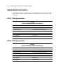
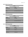
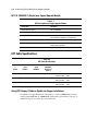
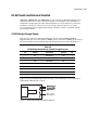
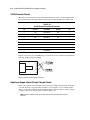
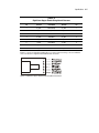
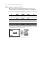
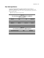
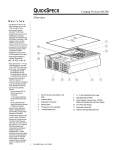
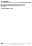
NC3134 Fast Ethernet Server Adapter User Guide Third Edition (June 2007) Part Number 174846-00F Compaq Computer Corporation Notice © 2001, 2007 Compaq Information Technologies Group, L.P. Compaq, the Compaq logo, and ProLiant are registered in U.S. Patent and Trademark Office. Microsoft, Windows, and Windows NT are trademarks of Microsoft Corporation in the United States and other countries. Intel is a trademark of Intel Corporation in the United States and other countries. The Open Group and UNIX are trademarks of The Open Group in the United States and other countries. All other product names mentioned herein may be trademarks of their respective companies. Compaq shall not be liable for technical or editorial errors or omissions contained herein. The information in this document is provided “as is” without warranty of any kind and is subject to change without notice. The warranties for Compaq products are set forth in the express limited warranty statements accompanying such products. Nothing herein should be construed as constituting an additional warranty. Compaq NC3134 Fast Ethernet Server Adapter User Guide Third Edition (June 2007) Part Number 174846-00F Contents About This Guide Symbols in Text .......................................................................................................... v Compaq Technician Notes ......................................................................................... vi Where to Go for Additional Help............................................................................... vi Compaq Customer Support ....................................................................................... vii Compaq Website................................................................................................ vii PaqFax Number ................................................................................................. vii Calling the Compaq Support Line .................................................................... viii Chapter 1 Introduction Overview.................................................................................................................. 1-1 NC3134 Adapter ............................................................................................... 1-2 Upgrade Modules.............................................................................................. 1-3 LED Indicator Descriptions .............................................................................. 1-4 UTP and Fiber Cable Specifications................................................................. 1-6 Chapter 2 Installing the Upgrade Module and Adapter Electrostatic Discharge Precautions ......................................................................... 2-1 Attaching the Upgrade Module................................................................................ 2-2 Removing the Adapter from a Server ............................................................... 2-2 Installing the Upgrade Module on the Adapter................................................. 2-2 Installing the Adapter in a Server............................................................................. 2-4 Connecting the Network Cable ................................................................................ 2-5 Connecting UTP Network Cable ...................................................................... 2-5 Connecting Fiber Network Cable ..................................................................... 2-5 Connecting and Using Loop-Back Plugs ................................................................ 2-6 RJ-45 Loop-Back Plug...................................................................................... 2-6 Appendix A Regulatory Compliance Notices Federal Communications Commission Notice........................................................ A-1 Class A Equipment .......................................................................................... A-1 Class B Equipment........................................................................................... A-2 Modifications ................................................................................................... A-2 Declaration of Conformity for products marked with the FCC logo - United States only........................................................................................................ A-2 Canadian Notice (Avis Canadien)........................................................................... A-3 Class A Equipment .......................................................................................... A-3 iv Compaq NC3134 Fast Ethernet Server Adapter User Guide Class B Equipment........................................................................................... A-3 European Union Notice........................................................................................... A-3 China Taiwan Notice .............................................................................................. A-3 Japanese Notice....................................................................................................... A-4 Appendix B Electrostatic Discharge Grounding Methods ................................................................................................ B-1 Appendix C Specifications NC3134 Fast Ethernet Server Adapter Specifications ............................................ C-1 Upgrade Module Specifications.............................................................................. C-2 NC3132 10/100 Upgrade Module.................................................................... C-2 NC3135 10/100 Upgrade Module.................................................................... C-2 NC6132 1000BASE-SX Upgrade Module ...................................................... C-3 NC6133 1000BASE-LX Upgrade Module ...................................................... C-3 NC3133 100BASE-FX Upgrade Module ........................................................ C-3 NC7132 1000BASE-T (Gigabit over Copper) Upgrade Module..................... C-4 UTP Cable Specifications ....................................................................................... C-4 Using UTP Category 5 Cable in Gigabit over Copper Installations ................ C-4 RJ-45 Pinouts and Crossover Function ................................................................... C-5 10/100 Straight-Through Pinouts..................................................................... C-5 10/100 Crossover Pinouts ................................................................................ C-6 Gigabit over Copper Internal Straight-Through Pinouts.................................. C-6 Gigabit over Copper External Crossover Pinouts ............................................ C-8 Fiber Cable Specifications ...................................................................................... C-9 About This Guide This user guide can be used for reference when installing the Compaq NC3134 Fast Ethernet Server Adapter or one of its upgrade modules. WARNING: To reduce the risk of personal injury from electrical shock and hazardous energy levels, only authorized service technicians should attempt to repair this equipment. Improper repairs could create conditions that are hazardous. IMPORTANT: The installation of options and servicing of this product shall be performed by individuals who are knowledgeable of the procedures, precautions, and hazards associated with equipment containing hazardous energy circuits. Symbols in Text These symbols may be found in the text of this guide. They have the following meanings. WARNING: Text set off in this manner indicates that failure to follow directions in the warning could result in bodily harm or loss of life. CAUTION: Text set off in this manner indicates that failure to follow directions could result in damage to equipment or loss of information. IMPORTANT: Text set off in this manner presents clarifying information or specific instructions. NOTE: Text set off in this manner presents commentary, sidelights, or interesting points of information. vi Compaq NC3134 Fast Ethernet Server Adapter User Guide Compaq Technician Notes WARNING: Only authorized technicians trained by Compaq should attempt to repair this equipment. All troubleshooting and repair procedures are detailed to allow only subassembly/module level repair. Because of the complexity of the individual boards and subassemblies, no one should attempt to make repairs at the component level or to make modifications to any printed wiring board. Improper repairs can create a safety hazard. Any indications of component replacement or printed wiring board modifications may void any warranty. WARNING: To reduce the risk of personal injury from electrical shock and hazardous energy levels, do not exceed the level of repair specified in these procedures. Because of the complexity of the individual boards and subassemblies, do not attempt to make repairs at the component level or to make modifications to any printed wiring board. Improper repairs could create conditions that are hazardous. WARNING: To reduce the risk of electric shock or damage to the equipment: If the system has multiple power supplies, disconnect power from the system by unplugging all power cords from the power supplies. Do not disable the power cord grounding plug. The grounding plug is an important safety feature. Plug the power cord into a grounded (earthed) electrical outlet that is easily accessible at all times. CAUTION: To properly ventilate your system, you must provide at least 12 inches (30.5 cm) of clearance at the front and back of the computer. CAUTION: The computer is designed to be electrically grounded. To ensure proper operation, plug the AC power cord into a properly grounded AC outlet only. Where to Go for Additional Help HP updates networking software frequently to include new functionality and features. Complete the following steps to get the latest drivers, firmware, and documentation. 1. Go to the HP website (http://www.hp.com). 2. Click Support and Troubleshooting Information from the left menu bar. 3. Type the product name in the for product box and press Enter. For example, type NC370T. Download the drivers, firmware, or documentation as needed. About This Guide Compaq Customer Support You can reach Compaq automated support services 24 hours a day, every day at no charge. The services provide the most up-to-date information about Compaq products. You can access installation instructions, troubleshooting information, and general product information from the Compaq website. For comprehensive online support, refer to: http://www.compaq.com For international information, refer to: http://www.compaq.com/corporate/overview/world_offices.html Compaq Website For Compaq Web-based support services, visit: http://www.compaq.com/support Navigate to a specific product and then look for support information from this list of support resources. For a complete list of available SoftPaq files, navigate to: http://www.compaq.com/support/files/allsp.html Send email to: [email protected] PaqFax Number The Compaq fax-on-demand retrieval system provides product-specific information. To use the fax system, you must be in North America and you must have a fax machine or fax modem to receive the automated fax transmittals. Call 1-800-345-1518, option 1, and request a product catalog. After you receive the catalog, you can order the documents through the Compaq faxon-demand retrieval system. vii viii Compaq NC3134 Fast Ethernet Server Adapter User Guide Calling the Compaq Support Line When you call the Compaq Support line, you must be at your server with your software running and the product documentation at hand. The Compaq technician may ask for the following information: ■ Your address and telephone number ■ The name and model number of the Compaq product you are calling about ■ The serial number of your Compaq product ■ The names and version numbers of the software you are using to operate the Compaq product ■ The name and version number of the operating system you are using ■ The system type (manufacturer and model number) ■ The expansion boards or add-in cards in your server ■ The amount of memory in your server North America The Compaq Customer Support department for North America can be reached at 1-800-652-6672 (1-800-OKCOMPAQ). For continuous quality improvement, calls may be monitored or recorded. Europe, the Middle East, and Africa In Europe, the Middle East, and Africa, contact your local Compaq authorized service provider. Details of your local Compaq authorized service provider can be obtained from your Compaq authorized reseller, dealer, or from the Compaq website at: http://www.compaq.com Worldwide Access Compaq has technical support centers worldwide. Many of the centers are staffed by technicians who speak the local languages. For a list of Compaq support centers, go to: http://www.compaq.com From the Compaq Worldwide home page, select your country and click Go to find the nearest Compaq office. Chapter 1 Introduction Overview The Compaq NC3134 Fast Ethernet Server Adapter is a second-generation, dual-port adapter that offers improved performance over earlier versions of the product. This improvement is due to the 64-bit/66MHz PCI-to-PCI bridge, as well as to the enhanced MAC silicon technology not previously available. The NC3134 adapter supports existing 10/100 Ethernet, 100FX, and 1000 SX/LX upgrade modules, which are listed in Table 1-1. The NC3134 adapter is a supported option for selected Compaq ProLiant™ servers. The new NC7132 upgrade module, described later in this chapter, has one RJ-45 connector and a 10/100/1000 Mb/s port that delivers up to 1000 Mb/s Ethernet over twisted-pair cabling (Gigabit over copper). Table 1-1 describes the adapter and upgrade modules. Table 1-1 NC3134 Adapter and Upgrade Modules with Port and Connection Options Name Type Number and Types of Ports Connection Option NC3134 Server adapter Two RJ-45 10BASE-T/100BASE-TX NC3133 Upgrade module One SC fiber 100BASE-FX NC3135 Upgrade module Two RJ-45 10BASE-T/100BASE-TX NC6132 Upgrade module One SC fiber 1000BASE-SX NC6133 Upgrade module One SC fiber 1000BASE-LX NC7132 Upgrade module One RJ-45 10BASE-T/100BASE-TX/ 1000BASE-T (Gigabit over copper) For the latest functionality, features, and operating system support for this server adapter, see the networking page at compaq.com 1-2 Compaq NC3134 Fast Ethernet Server Adapter User Guide Hardware Overview IMPORTANT: Two other devices, described separately in the Compaq NC3131 Fast Ethernet Server Adapter User Guide (available on the Compaq Website at www.compaq.com/support), are compatible with the NC3134 and the upgrade modules and drivers listed in this guide. These devices are: ■ The NC3131 Fast Ethernet Server Adapter, which supports all the upgrade modules described in this guide ■ The NC3132 Dual 10/100 Upgrade Module, which you can install in the NC3131 or the NC3134 Fast Ethernet Server Adapters The Compaq NC3134 Fast Ethernet server adapter is a high performance, upgradeable adapter with two fully-integrated 10BASE-T/100BASE-TX networking chips. The adapter contains a sophisticated 32-bit MAC with enhanced scatter-gather and bus-mastering capabilities. Its true 32-bit architecture enables it to perform high-speed data transfers on the PCI bus using four DMA channels. It can process high-level commands and perform multiple operations without processor intervention. The NC3134 adapter operates in a standard 32-bit PCI slot, supports both 32-bit and 64-bit systems, and can operate at 33MHz or 66MHz depending on the system. NC3134 Adapter The NC3134 adapter has two RJ-45 dual-speed ports. LEDs on each port indicate link, activity, and port speed. NOTE: Transmission speed is indicated by the color of the LNK and ACT LED indicators. See Table 1-2 for more information. Figure 1-1. NC3134 Server Adapter 10BASE-T/100BASE-TX RJ-45 ports and LED indicators Introduction 1-3 Upgrade Modules The NC3134 adapter supports the following upgrade modules: NOTE: See the section titled “LED Indicator Descriptions” for descriptions of LED indicator functions. NC3135 Upgrade Module The NC3135 upgrade module has two RJ-45 dual-speed ports and associated LEDs indicating link, activity, and speed. Figure 1-2. NC3135 Upgrade Module 10/100 ports and LED indicators NC7132 Upgrade Module The NC7132 upgrade module has one RJ-45 auto-negotiating tri-speed port and associated LEDs indicating link, activity, and speed. It supports UTP (Gigabit over copper) cabling. Figure 1-3. NC7132 Gigabit over copper upgrade module and LED indicators 1-4 Compaq NC3134 Fast Ethernet Server Adapter User Guide NC3133, NC6132, and NC6133 Fiber Upgrade Modules The NC3133, NC6132, and NC6133 fiber upgrade modules each have one SC fiber port and LEDs indicating link and activity. Figure 1-4. NC3133, NC6132, and NC6133 fiber SC port and LED indicators LED Indicator Descriptions NC3134 and NC3135 LED Indicators The Compaq NC3134 adapter and NC3135 upgrade modules have two diagnostic LED indicators for each RJ-45 port. The speed of the transmission (10 or 100 Mb/s) is indicated by the LED color. Table 1-2 10/100 LED Operations for the NC3134 Adapter and NC3135 Upgrade Module LED Display Description LNK On -- Amber The adapter is receiving power; the cable connection between the hub/switch and adapter is good and the link is established at 10 Mb/s. On -- Green The adapter is receiving power; the cable connection between the hub/switch and adapter is good and the link is established at 100 Mb/s. Off The adapter is not receiving power or the cable connection between the hub/switch and adapter is faulty. Blinking Amber The adapter is sending or receiving network data at 10 Mb/s. Blinking Green The adapter is sending or receiving network data at 100 Mb/s. Off The adapter is not sending or receiving network data. ACT Introduction 1-5 NC7132 LED Indicators The Compaq NC7132 upgrade module has four diagnostic LED indicators (see Figure 1-3). LED colors change with different link and activity (transmission/reception) speeds. Table 1-3 NC7132 Gigabit Upgrade Module LED Indicators LED Display Description Link/Speed Amber Link is established to the adapter at 10 Mb/s. The adapter is receiving power and the cable connection is good. Green Link is established to the adapter at 100 Mb/s. The adapter is receiving power and the cable connection is good. Blue Link is established to the adapter at 1000 Mb/s. The adapter is receiving power and the cable connection is good. Off No network data is being sent or received. The adapter is not receiving power or the cable connection is faulty. Amber The adapter is sending or receiving network data at 10 Mb/s Green The adapter is sending or receiving network data at 100 Mb/s Blue The adapter is sending or receiving network data at 1000 Mb/s Off The adapter is not sending or receiving network data. Activity/Speed Fiber Upgrade Module LED Indicators The fiber upgrade modules have two LEDs that indicate port operation, as described below. Table 1-4 Fiber Upgrade Module LED Operations for NC3133, NC6132, and NC6133 LED Display Description LNK On -- Green The adapter is receiving power, the connection is good, and the link to the adapter is established. Off No link is established. The adapter is not receiving power or the connection is faulty. Blinking Green The adapter is sending or receiving network data. Off No network data is being sent or received. The adapter is not receiving power or the connection is faulty. ACT UTP and Fiber Cable Specifications The NC7132 upgrade module can use existing Category 5 (or better) cable to deliver Gigabit Ethernet over copper, according to the IEEE 802.3ab specifications. For new installations, Category 5e cable is recommended. For more information about cabling, see “UTP Cable Specifications,” and “Fiber Cable Specifications,” in Appendix C. Chapter 2 Installing the Upgrade Module and Adapter This chapter describes installation precautions, how to attach upgrade modules to the adapter, and how to install the adapter. It also describes how to attach the network cable and the loopback plugs. WARNING: To avoid the risk of personal injury or damage to the equipment, consult the Safety information and user documentation provided with your equipment before attempting the installation. Many servers are capable of producing energy levels that are considered hazardous. Users should not remove enclosures nor should they bypass the interlocks provided for removal of these hazardous conditions. Installation of this adapter should be performed by individuals who are both qualified in the servicing of computer equipment and trained in the hazards associated with products capable of producing hazardous energy levels. NOTE: Before removing the cover of your server, refer to the Compaq documentation for the proper method of installing a PCI card and safeguarding yourself from electrical shock hazards. Electrostatic Discharge Precautions A discharge of static electricity from a finger or other conductor can damage components on the adapter. This can make the adapter inoperable. In addition to the following information, see Appendix B for more precautions. To prevent electrostatic damage, observe the following precautions: ■ Always properly ground yourself when touching a static-sensitive component or assembly. ■ Avoid hand contact by transporting and storing parts in static-safe containers. ■ Keep electrostatic-sensitive parts in their containers until they arrive at static-free locations. ■ Place parts on a grounded surface before removing them from their containers. ■ Avoid touching pins, leads, or circuitry. 2-2 Compaq NC3134 Fast Ethernet Server Adapter User Guide Attaching the Upgrade Module The Compaq NC3134 Fast Ethernet Server Adapter design lets you attach an upgrade module. This increases the number of RJ-45 ports to four, in addition to adding one 100 Mb/s FX fiber port, one 1000 Mb/s fiber port, or one RJ-45 port that delivers 1000 Mb/s over twisted-pair (Gigabit over copper) cabling. A Compaq Fast Ethernet or Gigabit upgrade module comes factory-assembled with a plastic extension bracket (clamp) installed on the module. A kit packaged with each upgrade module contains the following parts to attach the module to the adapter: ■ Two rivet assemblies — two hollow rivets and two flat-headed rivet pins ■ Read This First card — Instructions for attaching the upgrade module Removing the Adapter from a Server If the adapter is already installed in a Compaq ProLiant server, you must first remove it to install the upgrade module. If the adapter is not installed, go to the section titled “Installing the Upgrade Module on the Adapter.” NOTE: See the Compaq ProLiant PCI Hot Plug documentation for general information on removing the adapter. 1. If the server is not PCI Hot Plug compliant, power down the server and unplug the power cord. 2. Remove the server’s cover. WARNING: To reduce the risk of personal injury from hot surfaces, allow the internal system components to cool before touching them. CAUTION: If the server is not PCI Hot Plug compliant, power it down and unplug the power cord from the power outlet before removing the server cover. Failure to do so may damage the adapter or server. 3. Remove the screw or clip holding the adapter in the server, then slide the adapter out of the PCI slot. Installing the Upgrade Module on the Adapter Follow these steps to install the upgrade module. Refer to Figure 2-1 for more information. 1. Remove any adhesive strip (provided for safety) that is sealing the option door on the adapter. 2. Push and hold open the spring-loaded option door on the adapter. 3. Align the ports on the upgrade module with the option door opening, the two board-toboard connectors on the upgrade module with the two board-to-board connectors on the adapter, as well as the standoff (not included on all boards) on the upgrade module with the hole in the adapter. 4. Gently but firmly press the connectors and the standoff (not included on all boards) together until they are securely seated in each board. Installing the Upgrade Module and Adapter 5. Insert one hollow rivet through the adapter, and then through the extension bracket. When inserted properly, the lip of the hollow rivet is flush with the adapter and extends about 1/8 inch out of the bracket. 6. Insert one flat-headed pin into the hollow rivet until the head of the pin is flush with the lip of the hollow rivet. Flanges on the hollow rivet expand to hold the extension bracket tightly to the adapter. 7. Repeat steps 5 and 6 for the second rivet assembly. NOTE: To remove a rivet assembly: 1. Use the blunt end of a small screwdriver to push the rivet pin about 1/8 inch out of the hollow rivet. 2. Grasp the head of the rivet pin and pull it out of the hollow rivet. This releases the flanges on the hollow rivet. 3. Pull the hollow rivet out of the bracket. Figure 2-1. Installing an upgrade module on the adapter 2-3 2-4 Compaq NC3134 Fast Ethernet Server Adapter User Guide Installing the Adapter in a Server Refer to the Compaq ProLiant™ documentation for the specific steps necessary to safely install a PCI card in your server. Figure 2-2. Installing the adapter in a server 1. If you have not already done so, and if the server is not PCI Hot Plug compliant, power down the server and unplug the power cord. 2. Remove both the server cover and the cover bracket from a PCI slot. WARNING: To reduce the risk of personal injury from hot surfaces, allow the internal system components to cool before touching them. CAUTION: If the server is not PCI Hot Plug compliant, power it down and unplug the power cord from the power outlet before removing the server cover. Failure to do so may damage the adapter or server. 3. Firmly seat the adapter in a PCI slot and secure the adapter bracket. 4. Replace the server cover and plug in the power cord. Installing the Upgrade Module and Adapter Connecting the Network Cable Network connections for the adapter and upgrade modules use UTP or fiber cable. See the sections “UTP Cable Specifications” and “Fiber Cable Specifications” in Appendix C for a description of each upgrade module and the cable and mode each module supports. Connecting UTP Network Cable The ports on the NC3134 adapter and the NC3135 10/100 and NC7132 upgrade modules use the following UTP connectors. Table 2-1 UTP Network Cable Types Network Type Connector 10BASE-T network Category 3, 4 or 5 twisted-pair cable 100BASE-TX network Category 5 twisted-pair cable connected to a 100BASE-TX hub or switch 1000BASE-T network Category 5 (or better) twisted-pair cable connected to a 1000BASE-T hub or switch. This includes existing Gigabit over copper connections. For new Gigabit over copper installations, Category 5e – enhanced Category 5 -- is recommended. Note: If you use the adapter in a residential environment, you must use a Category 5 (or better) cable for both 10BASE-T and 100BASE-TX networks. The UTP network connections on the adapter and upgrade modules are RJ-45 connectors. To attach the cable, plug the cable connector into the port. When inserting an RJ-45 plug, ensure that the tab on the plug clicks into position indicating that it is properly seated. Connecting Fiber Network Cable The NC3133, NC6132, and NC6133 fiber upgrade modules use SC fiber ports. These ports support fiber with a maximum cable length dependent on the fiber type, mode, and cable size. See Appendix C for fiber cable specifications. To insert the network SC connector into the port of the upgrade module, line up the slot on the fiber connector with the key on the upgrade module and push gently until the retainers click into place. Figure 2-3. Inserting an SC fiber plug 2-5 2-6 Compaq NC3134 Fast Ethernet Server Adapter User Guide Connecting and Using Loop-Back Plugs RJ-45 loop-back plugs are supplied in the adapter and upgrade module packages. A fiber loopback plug is available in a spare parts kit. Install these plugs in any unused RJ-45 or fiber port on the adapter or module, as described in the following section. If the plug is not installed, you may get a cable fault or reduced functionality on the adapter or module, depending on the operating system you are running. RJ-45 Loop-Back Plug Each kit for the NC3134 adapter and the NC3135 upgrade module contains a loop-back plug. This loop-back plug consists of a single RJ-45 connector on a truncated cable. After you install the adapters in the server and connect the server to the network, insert this plug into any unused 10/100 ports on either the adapter or the upgrade module. For example, if you install an NC3135 upgrade module in an NC3134 adapter and connect two ports to the network, you may have up to two unused ports. In this example, you should insert the provided loop-back plugs into the unused ports. In addition, you can use the loop-back plug to diagnose the status of the adapter port without the adapter being on a live network. When you insert the loop-back plug into the port, the LNK LED for the port will light if the adapter port is operational, indicating that the link is established. Figure 2-4. Inserting a loop-back plug into an RJ-45 port Appendix A Regulatory Compliance Notices IMPORTANT: All of the following Regulatory Compliance Notices apply to the TX-based adapters and upgrade modules. For fiber adapters and fiber upgrade modules, only the European Union Notice applies. Federal Communications Commission Notice Part 15 of the Federal Communications Commission (FCC) Rules and Regulations has established Radio Frequency (RF) emission limits to provide an interference-free radio frequency spectrum. Many electronic devices, including computers, generate RF energy incidental to their intended function and are, therefore, covered by these rules. These rules place computers and related peripheral devices into two classes, A and B, depending upon their intended installation. Class A devices are those that may reasonably be expected to be installed in a business or commercial environment. Class B devices are those that may reasonably be expected to be installed in a residential environment (i.e., personal computers). The FCC requires devices in both classes to bear a label indicating the interference potential of the device as well as additional operating instructions for the user. The rating label on the device shows which class (A or B) the equipment falls into. Class B devices have an FCC logo or FCC ID on the label. Class A devices do not have an FCC logo or FCC ID on the label. Once the class of the device is determined, refer to the following corresponding statement. Class A Equipment This equipment has been tested and found to comply with the limits for a Class A digital device, pursuant to Part 15 of the FCC Rules. These limits are designed to provide reasonable protection against harmful interference when the equipment is operated in a commercial environment. This equipment generates, uses, and can radiate radio frequency energy and, if not installed and used in accordance with the instructions, may cause harmful interference to radio communications. Operation of this equipment in a residential area is likely to cause harmful interference, in which case the user will be required to correct the interference at personal expense. A-2 Compaq NC3134 Fast Ethernet Server Adapter User Guide Class B Equipment This equipment has been tested and found to comply with the limits for a Class B digital device, pursuant to Part 15 of the FCC Rules. These limits are designed to provide reasonable protection against harmful interference in a residential installation. This equipment generates, uses, and can radiate radio frequency energy and, if not installed and used in accordance with the instructions, may cause harmful interference to radio communications. However, there is no guarantee that interference will not occur in a particular installation. If this equipment does cause harmful interference to radio or television reception, which can be determined by turning the equipment off and on, the user is encouraged to try to correct the interference by one or more of the following measures: ■ Reorient or relocate the receiving antenna. ■ Increase the separation between the equipment and receiver. ■ Connect the equipment into an outlet on a circuit different from that to which the receiver is connected. ■ Consult the dealer or an experienced radio or television technician for help. Modifications The FCC requires the user to be notified that any changes or modifications made to this device that are not expressly approved by Compaq Computer Corporation may void the user's authority to operate the equipment. Declaration of Conformity for products marked with the FCC logo - United States only This device complies with Part 15 of the FCC Rules. Operation is subject to the following two conditions: (1) this device may not cause harmful interference, and (2) this device must accept any interference received, including interference that may cause undesired operation. For questions regarding your product, contact: Compaq Computer Corporation P. O. Box 692000, Mail Stop 530113 Houston, Texas 77269-2000 Or, call 1-800- 652-6672 (1-800-OK COMPAQ) For questions regarding this FCC declaration, contact: Compaq Computer Corporation P. O. Box 692000, Mail Stop 510101 Houston, Texas 77269-2000 Or, call (281) 514-3333 To identify this product, refer to the Part, Series, or Model number found on the product. Regulatory Compliance Notices A-3 Canadian Notice (Avis Canadien) Class A Equipment This Class A digital apparatus meets all requirements of the Canadian Interference-Causing Equipment Regulations. Cet appareil numérique de la classe A respecte toutes les exigences du Règlement sur le matériel brouilleur du Canada. Class B Equipment This Class B digital apparatus meets all requirements of the Canadian Interference-Causing Equipment Regulations. Cet appareil numérique de la classe B respecte toutes les exigences du Règlement sur le matériel brouilleur du Canada. European Union Notice Products with the CE Marking comply with both the EMC Directive (89/336/EEC) and the Low Voltage Directive (73/23/EEC) issued by the Commission of the European Community. Compliance with these directives implies conformity to the following European Norms (in brackets are the equivalent international standards): ■ EN55022 (CISPR 22)—Electromagnetic Interference ■ EN55024 (IEC61000-4-2,3,4,5,6,8,11)—Electromagnetic Immunity ■ EN61000-3-2 (IEC61000-3-2)—Power Line Harmonics ■ EN61000-3-3 (IEC61000-3-3)—Power Line Flicker ■ EN60950 (IEC950)—Product Safety China Taiwan Notice A-4 Compaq NC3134 Fast Ethernet Server Adapter User Guide Japanese Notice Appendix B Electrostatic Discharge To prevent damage to the system, be aware of the precautions you need to follow when setting up the system or handling parts. A discharge of static electricity from a finger or other conductor may damage system boards or other static-sensitive devices. This type of damage may reduce the life expectancy of the device. To prevent electrostatic damage, observe the following precautions: ■ Avoid hand contact by transporting and storing products in static-safe containers. ■ Keep electrostatic-sensitive parts in their containers until they arrive at static-free workstations. ■ Place parts on a grounded surface before removing them from their containers. ■ Avoid touching pins, leads, or circuitry. ■ Always be properly grounded when touching a static-sensitive component or assembly. Grounding Methods There are several methods for grounding. Use one or more of the following methods when handling or installing electrostatic-sensitive parts: ■ Use a wrist strap connected by a ground cord to a grounded workstation or computer chassis. Wrist straps are flexible straps with a minimum of 1 megohm ±10 percent resistance in the ground cords. To provide proper ground, wear the strap snug against the skin. ■ Use heel straps, toe straps, or boot straps at standing workstations. Wear the straps on both feet when standing on conductive floors or dissipating floor mats. ■ Use conductive field service tools. ■ Use a portable field service kit with a folding static-dissipating work mat. If you do not have any of the suggested equipment for proper grounding, have a Compaq authorized reseller install the part. NOTE: For more information on static electricity or assistance with product installation, contact your Compaq authorized reseller. Appendix C Specifications NC3134 Fast Ethernet Server Adapter Specifications Table C-1 NC3134 Fast Ethernet Server Adapter Specifications Specification Description Network Controller Chipset Intel 82559 MAC/PHY Data Transfer Method 64-bit/66MHz PCI, compatible with 64-bit/33MHz or 32-bit/33MHz Bus Master DMA Standards Supported IEEE 802.3x, 802.3u,802.3ad (static configuration mode only), 802.1p, and 802.1Q Dimensions 7.4 x 5.0 inches (L x W) 18.8 cm x 12.7 cm (including bracket) Connector See Table C-8 Distance 100 meters (328 feet) Interrupts Supported Automatically configured Temperature Range Operating: 0° C to 55° C / 32° F to 131° F Storage: -65° C to 85° C / -85° F to 185° F Relative Humidity Operating: 10% to 90% Storage: 5% to 95% Agency Approvals ■ ■ ■ ■ ■ Power Requirement 500 mA @ 5V max Data Transmission Rate 10/100 (Full- and Half-duplex) FCC Class B VCCI Class B BSMI Class A CISPR 22 Class B EN60950 ■ ■ ■ ■ ■ EN 55022 Class B EN55024 UL Canada UL ICES-003 Class B C-2 Compaq NC3134 Fast Ethernet Server Adapter User Guide Upgrade Module Specifications Environmental and safety specifications for the upgrade modules are the same as those for the NC3134 Server Adapter, as shown in Table C-1. All other specifications are the same except where noted. NC3132 10/100 Upgrade Module Table C-2 NC3132 10/100 Upgrade Module Specifications Specification Description Network Controller Chipset Intel 82558 MAC/PHY Standards Supported IEEE 802.3x, 802.3u,802.1p, and 802.1Q Connector and Distances See Table C-8 Dimensions 5.7 x 3.9 inches (L x W), 16.5 cm x 64 cm Agency Approvals See Table C-1 Power Requirements 800 mA @ 5V max NC3135 10/100 Upgrade Module Table C-3 NC3135 10/100 Upgrade Module Specifications Specification Description Network Controller Chipset Intel 82559 MAC/PHY Standards Supported IEEE 802.3x, 802.3u,802.1p, and 802.1Q Connector and Distances See Table C-8 Dimensions 5.7 x 3.9 inches (L x W) 16.5 cm x 64 cm Agency Approvals See Table C-1 Power Requirements 375 mA @ 5V max Specifications C-3 NC6132 1000BASE-SX Upgrade Module Table C-4 NC6132 1000SX Upgrade Module Specifications Specification Description Network Controller Chipset Intel 82542 MAC Standards Supported IEEE 802.3z (1000BASE-SX) Connector and Distances See Table C-13 Dimensions 6.5 x 2.5 inches (L x W) 16.5 cm x 6.4 cm Agency Approvals See Table C-1 Power Requirements 1025 mA @ 5V max NC6133 1000BASE-LX Upgrade Module Table C-5 NC6133 1000LX Upgrade Module Specifications Specification Description Network Controller Chipset Intel 82542 MAC Standards Supported IEEE 802.3z (1000BASE-LX) Connector and Distances See Table C-13 Dimensions 6.5 x 2.5 inches (L x W) 16.5 cm x 6.4 cm Agency Approvals See Table C-1 Power Requirements 1025 mA @ 5V max NC3133 100BASE-FX Upgrade Module Table C-6 NC3133 100FX Upgrade Module Specifications Specification Description Network Controller Chipset Intel 82558 MAC Standards Supported IEEE 802.3u (100BASE-FX) Connector and Distances See Table C-13 Dimensions 5.9 x 2.5 inches (L x W) 15.0 cm x 6.4 cm Agency Approvals See Table C-1 Power Requirements 1025 mA @ 5V max C-4 Compaq NC3134 Fast Ethernet Server Adapter User Guide NC7132 1000BASE-T (Gigabit over Copper) Upgrade Module Table C-7 NC7132 Gigabit over Copper Upgrade Module Specification Description Network Controller Chipset Intel 82543GC MAC Standards Supported IEEE 802.3ab, 802.1p, 802.3z, 802.3u Connector and Distances One RJ-45, 100 meters on Category 5 (or better); for new installations, Category 5e is recommended Dimensions 6.2 x 3.9 inches (L x W) Agency Approvals See product marking for FCC rating. See Table C-1 for all other Agency approvals. Power Requirements 2879 mA @5V maximum UTP Cable Specifications Table C-8 UTP Cable Specifications Adapter or Module Connection Speed (10 Mb/s) NC3134 Category 3, 4, or 5 NC3135 Category 3, 4, or 5 NC7132 Connection Speed (100 Mb/s) Connection Speed (1000 Mb/s, Gigabit over Copper) Wire EIA/TIA Distance Category 5 22-26 AWG, 100Ω @ 1 MHz 568a or 568b 100 meters Category 5 22-26 AWG, 100Ω @ 1 MHz 568a or 568b 100 meters 22-26 AWG, 100Ω @ 1 MHz 568a or 568b 100 meters Category 5 or better Using UTP Category 5 Cable in Gigabit over Copper Installations For Gigabit over copper installations, UTP Category 5 or better 1000BASE-T cable must comply with the IEEE 802.3ab 1000BASE-T standard. For new installations, Category 5e (enhanced Category 5) or better cable is recommended. Specifications C-5 RJ-45 Pinouts and Crossover Function 10BASE-T, 100BASE-TX, and 1000BASE-T are keyed systems to differentiate between voice and data transmissions, in order to keep them separate over twisted-pair cable. The Ethernet standard also specifies that each cable segment implement a crossover function to connect the transmitter of one device to the receiver of a device at the other end, and vice-versa. The crossover function may be implemented internally at the hub or switch, or externally, through the twisted-pair media. 10/100 Straight-Through Pinouts If the crossover function is implemented internally, the port is labeled MDI-X (Medium Dependent Interface–Crossover). When an MDI-X port is connected to an MDI port, the twisted pair media should be wired straight-through using the physical pinouts indicated in Table C-9. Table C-9 10/100 Pinouts Using Internal, Straight-Through Crossover Pin Function Color Match Function Pin 1 TD+ White/Orange TD+ 1 2 TD- Orange/White TD- 2 3 RD+ White/Green RD+ 3 4 Blue/White 4 5 White/Blue 5 6 RD- Green/White RD- 6 7 White/Brown 7 8 Brown/White 8 Figure C-1 shows straight-through connector wiring to be used when the crossover function is implemented within the hub or switch. Figure C-1. 10/100 straight-through wiring for RJ-45 connector C-6 Compaq NC3134 Fast Ethernet Server Adapter User Guide 10/100 Crossover Pinouts When the crossover function is not provided within the hub or switch, you must implement the crossover through the twisted-pair media using the physical pinouts indicated in Table C-10. Table C-10 10/100 Pinouts Using External Crossover Pin Function Color Match Function Pin 1 TD+ White/Orange RD+ 3 2 TD- Orange/White RD- 6 3 RD+ White/Green TD+ 1 TD- 2 4 Blue/White 5 White/Blue 6 RD- Green/White 7 White/Brown 8 Brown/White Figure C-2 shows the correct 10/100 wiring to use when the crossover function is implemented externally (in the twisted-pair cabling). Figure C-2. External crossover for RJ-45 connector Gigabit over Copper Internal Straight-Through Pinouts Unlike some connections in which the crossover function is implemented internally at the hub or switch, the NC7132 upgrade module provides its own automatic cross-over function. This means you can wire twisted-pair media straight-through for adapter-to-hub or switch or adapterto-adapter connections, using the pinouts shown in Table C-11. NOTE: To operate at Gigabit speeds, all four pairs of wires must be terminated within the RJ-45 connector. Specifications C-7 Table C-11 Gigabit over Copper Pinouts Using Internal Crossover Pin Function Color Match Function Pin 1 BI_DA+ White/Orange BI_DA+ 1 2 BI_DA- Orange/White BI_DA- 2 3 BI_DB+ White/Green BI_DB+ 3 4 BI_DC+ Blue/White BI_DC+ 4 5 BI_DC- White/Blue BI_DC- 5 6 BI_DB- Green/White BI_DB- 6 7 BI_DD+ White/Brown BI_DD+ 7 8 BI_DD- Brown/White BI_DD- 8 Figure C-3 shows straight-through Gigabit over copper connector wiring to be used when the crossover function is implemented within the hub or switch. Figure C-3. Gigabit over copper straight-through wiring for RJ-45 connector C-8 Compaq NC3134 Fast Ethernet Server Adapter User Guide Gigabit over Copper External Crossover Pinouts When a crossover function is not provided by either the adapter or hub or switch, you must implement it through the twisted-pair media using the physical pinouts shown in Table C-12. Table C-12 Gigabit over Copper Crossover Pinouts Pin Function Color Match Function Pin 1 BI_DA+ White/Orange BI_DB+ 3 2 BI_DA- Orange/White BI_DB- 6 3 BI_DB+ White/Green BI_DA+ 1 4 BI_DC+ Blue/White BI_DD+ 7 5 BI_DC- White/Blue BI_DD- 8 6 BI_DB- Green/White BI_DA- 2 7 BI_DD+ White/Brown BI_DC+ 4 8 BI_DD- Brown/White BI_DC- 5 Figure C-4 shows the correct Gigabit over copper wiring to be used when the crossover function is implemented externally (in the twisted-pair cabling). Figure C-4. Gigabit over copper external crossover for RJ-45 connector Specifications C-9 Fiber Cable Specifications To connect to the network, the NC3133, NC6132, and NC6133 upgrade modules use 100 BASE-FX, 1000 BASE-SX, or 1000BASE-LX fiber cable, respectively. Table C-13 and Table C-14 describe the fiber types, mode, cable size, and maximum distance specifications for the fiber upgrade modules. NOTE: All fiber upgrade modules use SC type connectors. Table C-13 Fiber Cable Maximum Distances for 1000BASE-SX, 1000BASE-LX (NC6132 and NC6133) Fiber Type Mode Size Max Distance 1000BASE-SX Multimode 62.5/125 µm 220 meters Multimode 50/125 µm 550 meters Multimode 62.5/125 µm 550 meters Multimode 50/125 µm 550 meters Single-mode 10µm 5000 meters 1000BASE- LX Table C-14 Fiber Cable Maximum Distances for 100BASE-FX (NC3133) Single Link Between Switches Mode Max Distance FX Multimode 2000 meters FX Multimode 25 km