1
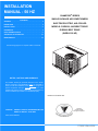
INSTALLATION
MANUAL - 50 HZ
CHAMPION® SERIES
CONTENTS
GENERAL . . . . . . . . . . . . . . . . . . . . . . . . . . . . . . . . . . . . . . 3
INSPECTION . . . . . . . . . . . . . . . . . . . . . . . . . . . . . . . . . . . . 3
SINGLE PACKAGE AIR CONDITIONERS
ELECTRIC/ELECTRIC, AIR-COOLED
INSTALLATION . . . . . . . . . . . . . . . . . . . . . . . . . . . . . . . . . . 3
MODELS: D1EB036, 048 DIRECT DRIVE
REFERENCE . . . . . . . . . . . . . . . . . . . . . . . . . . . . . . . . . . . . 3
D1EB060 BELT DRIVE
REPLACEMENT PARTS . . . . . . . . . . . . . . . . . . . . . . . . . . . 3
SEQUENCE OF OPERATION . . . . . . . . . . . . . . . . . . . . . . 14
(WORLD 50 HZ)
MAINTENANCE . . . . . . . . . . . . . . . . . . . . . . . . . . . . . . . . . 14
See following pages for a complete Table of Contents.
NOTES, CAUTIONS AND WARNINGS
The installer should pay particular attention to the words:
NOTE, CAUTION, and WARNING. Notes are intended to
clarify or make the installation easier. Cautions are given to
prevent equipment damage. Warnings are given to alert
installer that personal injury and/or equipment damage may
result if installation procedure is not handled properly.
Tested in accordance with:
CAUTION:
READ ALL SAFETY GUIDES BEFORE YOU
BEGIN TO INSTALL YOUR UNIT.
ISO 9001
Certified Quality
Management System
SAVE THIS MANUAL
173858-YIM-A-0306
173858-YIM-A-0306
TABLE OF CONTENTS
LIST OF FIGURES
GENERAL . . . . . . . . . . . . . . . . . . . . . . . . . . . . . . . . . . . . . . 3
INSPECTION . . . . . . . . . . . . . . . . . . . . . . . . . . . . . . . . . . . . 3
Fig. #
REFERENCE . . . . . . . . . . . . . . . . . . . . . . . . . . . . . . . . . . . . 3
1
REPLACEMENT PARTS . . . . . . . . . . . . . . . . . . . . . . . . . . 3
2
TYPICAL FIELD WIRING DIAGRAM . . . . . . . . . . . . . . 7
INSTALLATION . . . . . . . . . . . . . . . . . . . . . . . . . . . . . . . . . . 3
3
UNIT DIMENSIONS . . . . . . . . . . . . . . . . . . . . . . . . . . 13
LIMITATIONS . . . . . . . . . . . . . . . . . . . . . . . . . . . . . . . . . . 3
4
TYPICAL WIRING DIAGRAM 3 & 4 TON (380/415-3-50
POWER SUPPLY) . . . . . . . . . . . . . . . . . . . . . . . . . . . 15
5
TYPICAL WIRING DIAGRAM 5 TON (380/415-3-50
POWER SUPPLY) . . . . . . . . . . . . . . . . . . . . . . . . . . . 16
6
TYPICAL WIRING DIAGRAM LEGEND . . . . . . . . . . 17
7
TYPICAL WIRING DIAGRAM NOTES . . . . . . . . . . . . 17
LOCATION . . . . . . . . . . . . . . . . . . . . . . . . . . . . . . . . . . . . 3
RIGGING OR HANDLING . . . . . . . . . . . . . . . . . . . . . . . . . 4
CLEARANCES . . . . . . . . . . . . . . . . . . . . . . . . . . . . . . . . . 4
DUCT WORK . . . . . . . . . . . . . . . . . . . . . . . . . . . . . . . . . . 4
FILTERS . . . . . . . . . . . . . . . . . . . . . . . . . . . . . . . . . . . . . . 5
CENTER OF GRAVITY . . . . . . . . . . . . . . . . . . . . . . . . 4
LIST OF TABLES
CONDENSATE DRAIN . . . . . . . . . . . . . . . . . . . . . . . . . . . 5
SERVICE ACCESS . . . . . . . . . . . . . . . . . . . . . . . . . . . . . . 5
THERMOSTAT . . . . . . . . . . . . . . . . . . . . . . . . . . . . . . . . . 5
Pg. #
Tbl. #
Pg. #
POWER AND CONTROL WIRING . . . . . . . . . . . . . . . . . . 7
1
UNIT APPLICATION DATA . . . . . . . . . . . . . . . . . . . . . . 3
COMPRESSORS . . . . . . . . . . . . . . . . . . . . . . . . . . . . . . . 7
2
UNIT WEIGHTS AND CENTERS OF GRAVITY . . . . . . 4
CHECKING SUPPLY AIR CFM . . . . . . . . . . . . . . . . . . . . . . . . . 8
3
PHYSICAL DATA . . . . . . . . . . . . . . . . . . . . . . . . . . . . . 6
4
ELECTRICAL DATA . . . . . . . . . . . . . . . . . . . . . . . . . . . 8
SECURE OWNER'S APPROVAL . . . . . . . . . . . . . . . . . . 14
5
ADDITIONAL STATIC RESISTANCE . . . . . . . . . . . . . . 9
MAINTENANCE . . . . . . . . . . . . . . . . . . . . . . . . . . . . . . . . 14
6
D1EB036 SUPERHEAT CHARGING (IMPERIAL) . . . 10
NORMAL MAINTENANCE . . . . . . . . . . . . . . . . . . . . . . . 14
7
D1EB036 SUPERHEAT CHARGING (METRIC) . . . . . 10
8
D1EB048 SUPERHEAT CHARGING (IMPERIAL) . . . 11
9
D1EB048 SUPERHEAT CHARGING (METRIC) . . . . . 11
SEQUENCE OF OPERATION . . . . . . . . . . . . . . . . . . . . . 14
COOLING . . . . . . . . . . . . . . . . . . . . . . . . . . . . . . . . . . . . 14
10 D1EB060 SUPERHEAT CHARGING (IMPERIAL) . . . 12
11 D1EB060 SUPERHEAT CHARGING (METRIC) . . . . . 12
12 THERMOSTAT SIGNALS . . . . . . . . . . . . . . . . . . . . . . 14
2
Unitary Products Group
173858-YIM-A-0306
GENERAL
be made in writing. Refer to Form 50.15-NM for additional
information.
Model D1EB units are factory assembled cooling only air conditioners designed for outdoor installation on a rooftop or a
slab.
REFERENCE
Additional information on the design, installation, operation
and service of this equipment is available in the following reference forms:
The units are completely assembled on rigid, but easily
removable base rails. All piping, refrigerant charge, and electrical wiring is factory installed and tested. The units require
only electric power and duct connections at the point of installation.
•
•
INSPECTION
173858 - General Installation
036-21686-001 - Technical Guide
REPLACEMENT PARTS
As soon as a unit is received, it should be inspected for possible damage during transit. If damage is evident, the extent of
the damage should be noted on the carrier's freight bill. A
separate request for inspection by the carrier's agent should
Refer to Replacement Parts Manual for complete listing of
replacement parts on this equipment.
PRODUCT NOMENCLATURE
D
1
E B
0
3
6
A
5
PRODUCT CATEGORY
D = Single Package Air Conditioner
(Air Cooled)
PRODUCT GENERATION
1 = NEW or Current Design
NOMINAL COOLING
CAPACITY (MBH)
036 = 36,000 BTUH
048 = 48,000 BTUH
060 = 60,000 BTUH
PRODUCT IDENTIFIER
VOLTAGE CODE
50 = 380/415-3-50
FACTORY
INSTALLED ELECTRIC HEAT
A = No Electric Heat Installed
EB
INSTALLATION
0
TABLE 1: UNIT APPLICATION DATA
LIMITATIONS
Wet Bulb Temperature (°C) of Air on
Evaporator Coil,
Min. / Max.
14 / 22
These units must be installed in accordance with the following national and local safety codes.
Dry Bulb Temperature (°C) of Air on
Condenser Coil,
Min.1 / Max.
7 / 49
1.
National Electrical Code ANSI/NFPS No. 70 or Canadian
Electrical Code Part 1, C22.1 (latest editions).
2.
Local plumbing and waste water codes and other applicable local codes.
Refer to Table 1 for unit application data.
If components are to be added to a unit to meet local codes,
they are to be installed at the dealer's and/or the customer's
expense.
Size of unit for proposed installation should be based on heat
loss/heat gain calculations made in accordance with industry
recognized procedures identified by the Air Conditioning
Contractors of America.
Unitary Products Group
1.
A low ambient accessory is available for operation
down to 0°F.
LOCATION
Use the following guidelines to select a suitable location for
these units.
1.
Unit is designed for outdoor installation only.
2.
Condenser must have an unlimited supply of air. Where
a choice of location is possible, position unit on either
north or east side of building.
3.
For ground level installation, a level pad or slab should
be used. The thickness and size of the pad or slab used
3
173858-YIM-A-0306
should meet local codes and unit weight. Do not tie the
slab to the building foundation.
4.
5.
installation. Rig unit with slings placed under the unit.
Spreader bars of sufficient length should be used across the
top of the unit.
For roof top installation, be sure the structure will support
the weight of the unit plus any field installed components.
Unit must be installed on a level roof curb or appropriate
angle iron frame providing adequate support under the
compressor/condenser section.
BEFORE LIFTING A UNIT, MAKE SURE THAT ITS WEIGHT
IS DISTRIBUTED EQUALLY ON THE CABLES SO THAT IT
WILL LIFT EVENLY.
Units may also be moved or lifted with a fork-lift. Slotted
openings in the skid are provided for this purpose. Forks
must pass completely through the base.
Maintain level tolerance of unit to 1/8" maximum.
RIGGING OR HANDLING
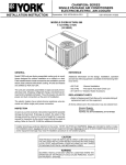
Refer to Table 2 for unit weights and to Figure 1 for approximate center of gravity.
Care must be exercised when moving the unit. Do not
remove any packaging until the unit is near the place of
TABLE 2: UNIT WEIGHTS AND CENTERS OF GRAVITY
SIZE
(Tons)
036
(3.0)
048
(4.0)
060
(5.0)
MODEL
UNIT WEIGHT
kg (lb)
Shipping
Operating
CENTER OF GRAVITY
mm (in.)
X
Y
A
4 POINT LOAD LOCATION
kg (lb)
B
C
D
DEB
150 (330)
147 (325)
610 (24)
597 (23.5)
35 (77)
35 (78)
39 (85)
38 (84)
DEB
179 (395)
177 (390)
610 (24)
597 (23.5)
42 (93)
43 (94)
46 (102)
46 (101)
DEB
222 (490)
220 (485)
572 (22.5)
610 (24)
57 (125)
51 (112)
53 (117)
60 (131)
&(17(52)*5$9,7<
³'´
)5217
2)
81,7
³&´
³$´
³%´
<
;
FIGURE 1 - CENTER OF GRAVITY
DUCT WORK
CLEARANCES
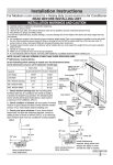
All units require certain clearances for proper operation and
service. Refer to Figure 3 for the clearances required for
combustion, construction, servicing and proper unit operation.
These units are adaptable to downflow use as well as rear
supply and return air duct openings. To convert to downflow,
use the following steps:
1.
Remove the duct covers found in the bottom return and
supply air duct openings. There are four (4) screws
securing each duct cover (save these screws to use
later).
2.
Install the duct covers, removed in step one, to the rear
supply and return air duct openings. Secure with the four
(4) screws used in step one.
3.
Seal the duct covers with silicone caulking.
Do not permit overhanging structures or shrubs to
obstruct the condenser air discharge outlet.
Downflow units must have an L-shaped supply duct without
any outlets or registers located directly below the supply outlet of the unit.
4
Unitary Products Group
173858-YIM-A-0306
Duct work should be designed and sized according to the
methods of the Air Conditioning Contractors of America
(ACCA), as set forth in their Manual D.
Filters should be checked monthly especially since this unit
may be used for both heating and cooling.
CONDENSATE DRAIN
A closed return duct system shall be used. This shall not preclude use of economizers or ventilation air intake. Flexible
joints may be used in the supply and return duct work to minimize the transmission of noise.
A condensate trap is required to be installed in the condensate drain. The plumbing must conform to local codes. Use a
sealing compound on male pipe threads. Install the condensate drain line (3/4“ NPTF) to spill into an open drain.
SERVICE ACCESS
When fastening duct work to the side duct flanges
on the unit, insert the screws through the duct
flanges only. DO NOT insert the screws through the
casing. Outdoor duct work must be insulated and
waterproofed.
NOTE: Be sure to note supply and return openings.
Refer to Figure 3 for information concerning rear and bottom
supply and return air duct openings.
Access to all serviceable components is provided by the following removable panels:
•
•
•
Blower service access
Electrical/filter access
Compressor service access
Refer to Figure 3 for location of these access panels and minimum clearance.
THERMOSTAT
FILTERS
A filter rack and filters are standard on all units.
Filters must always be used and must be kept clean. When
filters become dirt laden, insufficient air will be delivered by
the blower, decreasing your units efficiency and increasing
operating costs and wear-and-tear on the unit and controls.
Unitary Products Group
The room thermostat should be located on an inside wall
approximately 56" above the floor where it will not be subject
to drafts, sun exposure or heat from electrical fixtures or
appliances. Follow manufacturer's instructions enclosed with
the thermostat for general installation procedure. Four or five
color coded insulated wires (minimum #18 AWG) should be
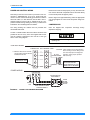
used to connect thermostat to unit. See Figure 2.
5
173858-YIM-A-0306
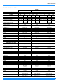
TABLE 3: PHYSICAL DATA
COMPONENT
NOMINAL TONNAGE
COOLING PERFORMANCE
RATING
Indoor DB/WB °C
Outdoor DB/WB °C
Total Output (MBH)
Total Output kW (MBH)
Total Input kW
COP²
Refrigerant charge kg (lb)
Refrigerant type
DIMENSIONS (inches)
Length mm (in.)
Width mm (in.)
Height mm (in.)
OPERATING WT. kg (lb)
COMPRESSORS
Type
Quantity
CONDENSER COIL DATA
Face area m² (ft²)
Rows
Fins per cm (in.)
Tube diameter mm (in.)
Circuitry Type
EVAPORATOR COIL DATA
Face area m² (ft²)
Rows
Fins per cm (in.)
Tube diameter mm (in.)
Circuitry Type
Refrigerant control
CONDENSER FAN DATA
Quantity
Fan diameter mm (in.)
Type
Drive type
No. speeds
Number of motors
Motor HP each
RPM
Nominal total m3/s (cfm)
BLOWER DATA
Quantity
Centrifugal Blower Dia. x Wd. mm (in)
Type
Motor HP each
RPM
Frame size
DEB036
3.0
MODELS
DEB048
4.0
DEB060
5.0
T1
T2
T2
T1
T2
T3
T1
T2
T3
27 / 19
29 / 19
21 / 15
27 / 19
29 / 19
21 / 15
27 / 19
29 / 19
21 / 15
35 / 24
46 / 24
27 / 19
35 / 24
46 / 24
27 / 19
35 / 24
46 / 24
27 / 19
36500
30550
34500
47000
40900
45000
58300
50800
54500
125 / 36.5 104 / 30.6 118 / 34.5 160 / 47 140 / 40.9 154 / 45 199 / 58.3 173 / 50.8 186 / 54.5
4.25
4.72
3.75
5.07
6.14
4.40
6.00
7.25
5.20
2.52
1.90
2.70
2.72
1.95
3.00
2.85
2.05
3.07
4.05 (8.94)
2.49 (5.5)
4.05 (8.94)
R-22
R-22
R-22
1248 (49.13)
1200 (47.25)
851 (33.50)
147 (325)
1248 (49.13)
1200 (47.25)
1048 (41.25)
177 (390)
1248 (49.13)
1200 (47.25)
1048 (41.25)
220 (485)
Scroll 1-spd
1
Scroll 1-spd
1
Scroll 1-spd
1
0.77 (8.3)
1
7.88 (20)
10 (0.375)
Interlaced
1.47 (15.8)
1
6.30 (16)
10 (0.375)
Interlaced
1.47 (15.8)
2
7.88 (20)
10 (0.375)
Interlaced
0.41 (4.38)
2
5.91 (15)
10 (0.375)
Interlaced
Orifice
0.52 (5.62)
2
5.12 (13)
10 (0.375)
Interlaced
Orifice
0.52 (5.62)
3
6.30 (16)
10 (0.375)
Interlaced)
Orifice
1
559 (22)
Axial
Direct
1
1
1/2
900
1.42 (3000)
1
559 (22)
Axial
Direct
1
1
1/2
900
1.42 (3000)
1
559 (22)
Axial
Direct
1
1
1/2
900
1.42 (3000)
1
254 x 203
(10 x 8)
Centrifugal
3/4
Variable
48
1
279 x 254
(11 x 10)
Centrifugal
1
Variable
48
1
279 x 254)
(11 x 10)
Centrifugal
1
Variable
48
2-559 x 356 x 25
2-(22 x 14 x 1)
2-559 x 356 x 25
2-(22 x 14 x 1)
2-559 x 356 x 25
2-(22 x 14 x 1)
FILTERS
Quantity - Size mm (in)
6
Unitary Products Group
173858-YIM-A-0306
POWER AND CONTROL WIRING
Field wiring to the unit must conform to provisions of the current N.E.C. ANSI/NFPA No. 70 or C.E.C. and/or local ordinances. The unit must be electrically grounded in accordance
with local codes or, in their absence, with the N.E.C./C.E.C.
Voltage tolerances which must be maintained at the compressor terminals during starting and running conditions are
indicated on the unit Rating Plate and Table 3.
The wiring entering the cabinet must be provided with
mechanical strain relief.
Electrical line must be sized properly to carry the load. Each
unit must be wired with a separate branch circuit fed directly
from the meter panel and properly fused.
Refer to Figure 2 for typical field wiring and to the appropriate
unit wiring diagram for control circuit and power wiring information.
COMPRESSORS
Units are shipped with compressor mountings factoryadjusted for shipping.
A fused or HACR breaker disconnect switch should be field
provided for the unit. If any of the wire supplied with the unit
must be replaced, replacement wire must be of the type
shown on the wiring diagram.
Loosen compressor mounting bolts half turn before
operating unit.
&21752/:,5,1*
7+(50267$7 81,77(50,1$/675,3
0LQLPXPZLUHVL]HRI$:*
ZLUHVKRXOGEHXVHGIRUDOOILHOG
LQVWDOOHGYROWZLUH
5
352*5$00$%/(
7+(50267$721/<
5
*
*
<
<
:
:
&
&
&$87,21 /DEHODOOZLUHVSULRUWRGLVFRQQHFWLRQ
ZKHQVHUYLFLQJFRQWUROV:LULQJHUURUV
FDQFDXVHLPSURSHUDQGGDQJHURXV
RSHUDWLRQ9HULI\SURSHURSHUDWLRQ
92/7
75$16)250(5 DIWHUVHUYLFLQJ
127(
+($7$17,&,3$725
6+28/'%(6(7$7
$036)25$//02'(/6
32:(5:,5,1*
&217$&725
),(/'6833/,('
',6&211(&7
*5281'
/8*
5()(572(/(&75,&$/
'$7$7$%/(6726,=(
7+(',6&211(&7
7+5((
3+$6(
32:(5
6833/<
FIGURE 2 - TYPICAL FIELD WIRING DIAGRAM
Unitary Products Group
7
173858-YIM-A-0306
TABLE 4: ELECTRICAL DATA
SIZE
(TONS)
036
(3.0)
048
(4.0)
060
(5.0)
1.
2.
3.
COMPRESSOR
(EACH)
RLA LRA MCC
OD FAN
MOTORS
(EACH)
SUPPLY
BLOWER
MOTOR
MCA1
(AMPS)
MOCP2
(AMPS)
MAX. FUSE3
SIZE
(AMPS)
9.5
1.0
1.8
11.2
15
15
66.5
12.5
1.0
3.2
15.1
20
20
73.0
13.0
1.0
2.7
15.7
25
25
MODEL
POWER
DEB
380/415-3-50
6.7
39.0
DEB
380/415-3-50
8.7
DEB
380/415-3-50
10.4
Minimum Circuit Ampacity.
Maximum Over Current Protection per standard UL 1995.
Fuse or HACR circuit breaker size installed at factory or field installed.
CHECKING SUPPLY AIR CFM
To check the supply air CFM after the initial balancing has
been completed:
4.
Knowing the pressure drop across the coil, the actual
CFM through the unit can be determined from Table 5.
1.
Remove the two ¼ inch dot plugs in the duct panel.
2.
Insert at least 8 inches of ¼ inch tubing into each of
these holes for sufficient penetration into the airflow on
both sides of the indoor coil.
Failure to properly adjust the total system air quantity can result in extensive system damage.
3.
Using an inclined manometer, determine the pressure
drop across the evaporator coil.
After readings have been obtained, remove the tubes and
reinstall the two ¼ inch plugs removed in Step 1.
8
Unitary Products Group
173858-YIM-A-0306
TABLE 5: ADDITIONAL STATIC RESISTANCE
Size
(Tons)
Model
036
(3.0)
DEB
048
(4.0)
DEB
060
(5.0)
DEB
1.
Airflow
m3/s (cfm)
0.42 (900)
0.47 (1000)
0.52 (1100)
0.57 (1200)
0.61 (1300)
0.66 (1400)
0.71 (1500)
0.57 (1200)
0.61 (1300)
0.66 (1400)
0.71 (1500)
0.76 (1600)
0.80 (1700)
0.85 (1800)
0.90 (1900)
0.94 (2000)
0.71 (1500)
0.76 (1600)
0.80 (1700)
0.85 (1800)
0.90 (1900)
0.94 (2000)
0.99 (2100)
1.04 (2200)
1.09 (2300)
1.13 (2400)
1.18 (2500)
Wet Indoor
Coil
Pa (in.wc)
12.45 (0.05)
14.95 (0.06)
17.44 (0.07)
17.44 (0.07)
19.93 (0.08)
22.42 (0.09)
24.91 (0.1)
17.44 (0.07)
19.93 (0.08)
24.91 (0.1)
29.89 (0.12)
32.28 (0.13)
37.36 (0.15)
34.87 (0.14)
37.36 (0.15)
39.85 (0.16)
65.39 (0.26)
69.75 (0.28)
74.10 (0.3)
78.46 (0.32)
82.82 (0.33)
87.18 (0.35)
91.54 (0.37)
95.90 (0.39)
100.26 (0.4)
104.62 (0.42)
108.98 (0.44)
Economizer1
Pa (in.wc)
2.49 (0.01)
2.49 (0.01)
4.98 (0.02)
4.98 (0.02)
7.47 (0.03)
9.96 (0.04)
12.45 (0.05)
4.98 (0.02)
7.47 (0.03)
9.96 (0.04)
12.45 (0.05)
14.95 (0.06)
17.44 (0.07)
19.93 (0.08)
22.42 (0.09)
24.91 (0.1)
12.45 (0.05)
14.95 (0.06)
17.44 (0.07)
19.93 (0.08)
22.42 (0.09)
24.91 (0.1)
29.89 (0.12)
32.38 (0.13)
34.87 (0.14)
39.85 (0.16)
44.84 (0.18)
Filter / Frame
Kit
Pa (in.wc)
4.98 (0.02)
4.98 (0.02)
7.47 (0.03)
7.47 (0.03)
7.47 (0.03)
9.96 (0.04)
9.96 (0.04)
7.47 (0.03)
7.47 (0.03)
9.96 (0.04)
9.96 (0.04)
9.96 (0.04)
12.45 (0.05)
12.45 (0.05)
12.45 (0.05)
14.95 (0.06)
9.96 (0.04)
9.96 (0.04)
12.45 (0.05)
12.45 (0.05)
12.45 (0.05)
14.95 (0.06)
14.95 (0.06)
14.95 (0.06)
17.44 (0.07)
17.44 (0.07)
19.93 (0.08)
The pressure drop through the economizer is greater than 100% outdoor air than for 100% return air. If the resistance of
the return air duct is less than 0.25 IWG, the unit will deliver less CFM during full economizer operation.
Unitary Products Group
9
173858-YIM-A-0306
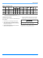
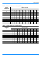
TABLE 6:
D1EB036 SUPERHEAT CHARGING (IMPERIAL)
SUPERHEAT AT COMPRESSOR SUCTION (°F)
AIRFLOW = 1,300 CFM
OUTDOOR
TEMPERATURE
(°F)
TABLE 7:
INDOOR WB TEMPERATURE (°F)
55
57
59
61
63
65
67
69
71
73
75
65
21.1
21.6
22.1
22.7
23.2
23.8
24.3
25.3
26.4
26.9
27.4
70
19.5
20.0
20.6
21.1
21.7
22.2
22.8
24.0
25.1
25.7
26.3
75
17.9
18.5
19.0
19.6
20.2
20.7
21.3
22.6
23.9
24.6
25.2
80
16.3
16.9
17.5
18.0
18.6
19.2
19.8
21.2
22.7
23.4
24.1
85
14.7
15.3
15.9
16.5
17.1
17.7
18.3
19.9
21.4
22.2
23.0
90
13.1
13.8
14.4
15.1
15.8
16.4
17.1
18.7
20.3
21.2
22.0
95
11.5
12.2
12.9
13.7
14.4
15.2
15.9
17.6
19.3
20.1
20.9
100
9.1
9.6
10.2
10.7
11.2
11.8
12.3
15.0
17.6
18.9
20.2
105
6.7
7.1
7.4
7.7
8.1
8.4
8.8
12.4
16.0
17.8
19.6
110
-
-
-
-
-
5.0
5.2
9.7
14.3
16.6
18.9
115
-
-
-
-
-
-
-
7.1
12.6
15.4
18.2
D1EB036 SUPERHEAT CHARGING (METRIC)
SUPERHEAT AT COMPRESSOR SUCTION (°C)
AIRFLOW = 0.61 M3/S
OUTDOOR
TEMPERATURE
(°C)
10
INDOOR WB TEMPERATURE (°C)
13
14
15
16
17
18
19
21
22
23
24
18
11.7
12.0
12.3
12.6
12.9
13.2
13.5
14.1
14.7
14.9
15.2
21
10.8
11.1
11.4
11.7
12.1
12.4
12.7
13.3
14.0
14.3
14.6
24
9.9
10.3
10.6
10.9
11.2
11.5
11.8
12.6
13.3
13.6
14.0
27
9.1
9.4
9.7
10.0
10.4
10.7
11.0
11.8
12.6
13.0
13.4
29
8.2
8.5
8.8
9.2
9.5
9.8
10.2
11.0
11.9
12.3
12.8
32
7.3
7.6
8.0
8.4
8.8
9.1
9.5
10.4
11.3
11.8
12.2
35
6.4
6.8
7.2
7.6
8.0
8.4
8.8
9.8
10.7
11.2
11.6
38
5.0
5.3
5.6
5.9
6.2
6.5
6.8
8.3
9.8
10.5
11.2
41
3.7
3.9
4.1
4.3
4.5
4.7
4.9
6.9
8.9
9.9
10.9
43
-
-
-
-
-
2.8
2.9
5.4
7.9
9.2
10.5
46
-
-
-
-
-
-
-
4.0
7.0
8.6
10.1
Unitary Products Group
173858-YIM-A-0306
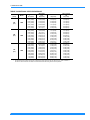
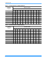
TABLE 8:
D1EB048 SUPERHEAT CHARGING (IMPERIAL)
SUPERHEAT AT COMPRESSOR SUCTION (°F)
AIRFLOW = 1,800 CFM
OUTDOOR
TEMPERATURE
(°F)
TABLE 9:
INDOOR WB TEMPERATURE (°F)
55
57
59
61
63
65
67
69
71
73
75
65
19.9
21.0
22.1
23.3
24.4
25.6
26.7
28.0
29.3
30.0
30.7
70
16.5
17.9
19.2
20.6
22.0
23.4
24.8
26.3
27.8
28.6
29.4
75
13.1
14.7
16.3
18.0
19.6
21.3
22.9
24.6
26.3
27.2
28.1
80
9.7
11.6
13.4
15.3
17.2
19.1
21.0
22.9
24.8
25.8
26.8
85
6.3
8.4
10.5
12.7
14.8
17.0
19.1
21.2
23.3
24.4
25.5
90
-
5.7
7.8
9.9
11.9
14.0
16.1
18.8
21.5
22.8
24.1
95
-
-
5.0
7.0
9.1
11.1
13.1
16.3
19.6
21.2
22.8
100
-
-
-
5.4
6.9
8.5
10.0
13.6
17.3
19.1
20.9
105
-
-
-
-
-
5.9
6.9
11.0
15.0
17.0
19.0
110
-
-
-
-
-
-
-
8.3
12.6
14.8
17.0
115
-
-
-
-
-
-
-
5.6
10.3
12.7
15.1
D1EB048 SUPERHEAT CHARGING (METRIC)
SUPERHEAT AT COMPRESSOR SUCTION (°C)
AIRFLOW = 0.85 M3/S
OUTDOOR
TEMPERATURE
(°C)
INDOOR WB TEMPERATURE (°C)
13
14
15
16
17
18
19
21
22
23
24
18
11.0
11.7
12.3
12.9
13.6
14.2
14.8
15.6
16.3
16.7
17.0
21
9.1
9.9
10.7
11.5
12.2
13.0
13.8
14.6
15.5
15.9
16.3
24
7.3
8.2
9.1
10.0
10.9
11.8
12.7
13.7
14.6
15.1
15.6
27
5.4
6.4
7.5
8.5
9.6
10.6
11.7
12.7
13.8
14.3
14.9
29
3.5
4.7
5.9
7.0
8.2
9.4
10.6
11.8
13.0
13.6
14.1
32
-
3.2
4.3
5.5
6.6
7.8
8.9
10.4
11.9
12.7
13.4
35
-
-
2.8
3.9
5.0
6.2
7.3
9.1
10.9
11.8
12.7
38
-
-
-
3.0
3.9
4.7
5.6
7.6
9.6
10.6
11.6
41
-
-
-
-
-
3.3
3.9
6.1
8.3
9.4
10.5
43
-
-
-
-
-
-
-
4.6
7.0
8.2
9.5
46
-
-
-
-
-
-
-
3.1
5.7
7.1
8.4
Unitary Products Group
11
173858-YIM-A-0306
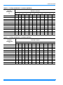
TABLE 10: D1EB060 SUPERHEAT CHARGING (IMPERIAL)
SUPERHEAT AT COMPRESSOR SUCTION (°F)
AIRFLOW = 2,000 CFM
OUTDOOR
TEMPERATURE
(°F)
INDOOR WB TEMPERATURE (°F)
55
57
59
61
63
65
67
69
71
73
75
65
21.9
23.8
25.7
27.6
29.4
31.3
33.2
34.2
35.1
35.6
36.1
70
16.0
18.4
20.7
23.0
25.3
27.6
30.0
31.3
32.7
33.4
34.0
75
10.1
12.9
15.7
18.4
21.2
23.9
26.7
28.5
30.2
31.1
32.0
80
-
7.5
10.7
13.9
17.1
20.3
23.5
25.6
27.8
28.9
29.9
85
-
-
5.6
9.3
12.9
16.6
20.2
22.8
25.3
26.6
27.9
90
-
-
-
7.6
10.6
13.6
16.7
19.8
22.9
24.4
26.0
95
-
-
-
5.9
8.3
10.7
13.1
16.7
20.4
22.2
24.0
100
-
-
-
-
6.4
8.2
10.1
13.2
16.3
17.9
19.5
105
-
-
-
-
-
5.8
7.0
9.6
12.3
13.6
14.9
110
-
-
-
-
-
-
-
6.1
8.2
9.3
10.4
115
-
-
-
-
-
-
-
-
-
-
5.8
TABLE 11: D1EB060 SUPERHEAT CHARGING (METRIC)
SUPERHEAT AT COMPRESSOR SUCTION (°C)
AIRFLOW = 0.94 M3/S
OUTDOOR
TEMPERATURE
(°C)
12
INDOOR WB TEMPERATURE (°C)
13
14
15
16
17
18
19
21
22
23
24
18
12.2
13.2
14.3
15.3
16.4
17.4
18.4
19.0
19.5
19.8
20.0
21
8.9
10.2
11.5
12.8
14.1
15.4
16.6
17.4
18.2
18.5
18.9
24
5.6
7.2
8.7
10.2
11.8
13.3
14.8
15.8
16.8
17.3
17.8
27
-
4.1
5.9
7.7
9.5
11.3
13.0
14.2
15.4
16.0
16.6
29
-
-
3.1
5.2
7.2
9.2
11.2
12.6
14.1
14.8
15.5
32
-
-
-
4.2
5.9
7.6
9.3
11.0
12.7
13.6
14.4
35
-
-
-
3.3
4.6
5.9
7.3
9.3
11.3
12.3
13.3
38
-
-
-
-
3.6
4.6
5.6
7.3
9.1
9.9
10.8
41
-
-
-
-
-
3.2
3.9
5.4
6.8
7.6
8.3
43
-
-
-
-
-
-
-
3.4
4.6
5.2
5.8
46
-
-
-
-
-
-
-
-
-
-
3.2
Unitary Products Group
173858-YIM-A-0306
+,*+92/7$*(&211
´',$.12&.287
)5217
&2035(6625
6(59,&($&&(66
&203$570(173$1(/
+,*+92/7$*(&211
´',$.12&.287
³$´
81,76,=(
/2:92/7$*(&211
´',$.12&.287
',0(16,21
³$´
29(5$//
6,'(6833/<
$,523(1,1*
5()5,*(5$17
&211(&7,216
6,'(5(7851
$,523(1,1*
(/(&75,&$/),/7(5
6(59,&($&&(66
&203$570(173$1(/
+,*+92/7$*(&211
´',$.12&.287
29(5$//
29(5$//
/2:92/7$*(
&211
´',$.12&.287
81,7&21'(16$7(
&211(&7,21´137,
75$35(48,5('
)5217
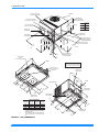
$OOGLPHQVLRQVDUHLQLQFKHV7KH\DUH
VXEMHFWWRFKDQJHZLWKRXWQRWLFH&HUWLILHG
GLPHQVLRQVZLOOEHSURYLGHGXSRQUHTXHVW
+,*+92/7$*(
&211´[´',$
.12&.287
6,'(6833/<
$,523(1,1*
&21'(16(5&2,/
%$&.
6,'(5(7851
$,523(1,1*
%277206833/<
$,523(1,1*
&21'(16$7(
'5$,1´137,
81,7&/($5$1&(6
'LUHFWLRQ
'LVWDQFH
PPLQ
'LUHFWLRQ
'LVWDQFH
PPLQ
7RS
5LJKW
)URQW
/HIW
5HDU
%RWWRP
8QLWVPXVWEHLQVWDOOHGRXWGRRUV2YHUKDQJLQJ
VWUXFWXUHRUVKUXEVVKRXOGQRWREVFXUHFRQGHQVHU
DLUGLVFKDUJHRXWOHW
8QLWVPD\EHLQVWDOOHGRQFRPEXVWLEOHIORRUVPDGH
IURPZRRGRUFODVV$%RU&URRIFRYHULQJPDWHUL
DOV
%277205(7851
$,523(1,1*
FIGURE 5 - UNIT DIMENSIONS
Unitary Products Group
13
173858-YIM-A-0306
SEQUENCE OF OPERATION
SECURE OWNER'S APPROVAL
COOLING
When the system is functioning properly, secure the owner's
approval. Show the owner the location of all disconnect
switches and the thermostat. Teach the owner how to start
and stop the unit and how to adjust temperature settings
within the limitations of the system.
The following sequences of operation are based on using a
standard single-stage cooling thermostat.
WITH POWER TO UNIT AND THERMOSTAT IN COOLING
MODE
MAINTENANCE
1.
If the fan switch on the thermostat is in the “ON” position,
the 24 volts at “G” will energize the “K1" relay on the fan
control board, close the ”K1" relay contacts, and energize the indoor blower motor. If the fan switch is in the
“AUTO” position, the blower will operate only when there
is a call for cooling by the thermostat.
NORMAL MAINTENANCE
2.
On a call for cooling, the thermostat will send 24 volts to
“Y” on the fan control board. The 24 volt signal will energize contactor “M1", and power will be supplied to the
compressor and outdoor fan motor. If the fan switch on
the thermostat is on the ”AUTO" position, the thermostat
will also send a 24 volt signal to “G” on the fan control
board and the indoor blower will operate as indicated in
step 1.
3.
When the demand for cooling has been satisfied, the
“M1" contactor will be de-energized when the 24 volt ”Y"
signal is removed. If the fan switch on the thermostat is
energized when the 24 volt “Y” signal is removed. If the
fan switch on the thermostat is in the “ON” position, the
indoor blower will continue to run. If the fan switch is in
the “AUTO” position, the 24 volt “G” signal will be
removed, and after a 60 second delay, the “K1" relay will
open and de-energize the indoor blower motor.
“G”
“G”
“Y”
14
STATE
SIGNAL
TABLE 12: THERMOSTAT SIGNALS
ON
Periodic maintenance consists of changing or cleaning filters
and general cleaning of the outdoor coil.
FILTERS - Inspect once a month. Replace Disposable or
clean Permanent Type as necessary. DO NOT replace Permanent Type with Disposable.
MOTORS - Indoor and outdoor fan motors are permanently
lubricated and require no maintenance.
OUTDOOR COIL - Dirt should not be allowed to accumulate
on the outdoor coil surface or other parts in the air circuit.
Cleaning should be as often as necessary to keep the coil
clean. Use a brush, vacuum cleaner attachment, or other
suitable means. If water is used to clean the coil, be sure that
the power to the unit is shut off prior to cleaning.
BOARD FUNCTION
FAN INSTANT ON
OFF FAN INSTANT OFF
ON
Prior to any of the following maintenance procedures, shut off all power to the unit, to avoid personal injury.
FAN INSTANT ON
COMPRESSOR AND OUTDOOR FAN INSTANT ON
COMPRESSOR AND OUTDOOR FAN INSTANT OFF
OFF
FAN 60 SECOND DELAY OFF
Exercise care when cleaning the coil so that the coil
fins are not damaged.
Do not permit the hot condenser air discharge to be
obstructed by overhanging structures or shrubs.
Unitary Products Group
173858-YIM-A-0306
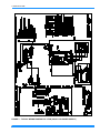
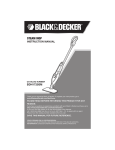
FIGURE 3 - TYPICAL WIRING DIAGRAM 3 & 4 TON (380/415-3-50 POWER SUPPLY)
Unitary Products Group
15
173858-YIM-A-0306
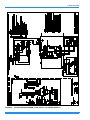
FIGURE 4 - TYPICAL WIRING DIAGRAM 5 TON (380/415-3-50 POWER SUPPLY)
16
Unitary Products Group
173858-YIM-A-0306
&%
&2035
)
)=
+3
.
.
/3
0
0
0
5&
5&
63
63
63
63
7
&,5&8,7%5($.(59$03
&2035(6625
)86(96(&21'$5<$03
)5((=(67$76:,7&+237,21$&&(6625<23(1#)
+,*+35(6685(6:,7&+237,21$/$&&(6625<23(16$736,*
5(/$<,1'225)$102725
5(/$<(/(&75,&+($7(5
/2:35(6685(6:,7&+237,21$/$&&(6625<23(1#36,*
&217$&725&2035(6625287'225)$1
&217$&725(/(&75,&+($79&2,/
&217$&725(/(&75,&+($79&2,/
287'225)$1581&$3$&,725$/7(51$7(
,1'225)$1581&$3$&,725
62&.(73/8*&211(&7,2121)$1&21752/%2$5'/2:92/7$*(
62&.(73/8*&211(&7,2121)$1&21752/%2$5'/,1(92/7$*(
62&.(73/8*&211(&7,2121,')$1027259
62&.(73/8*&211(&7,2121,')$1027259
75$16)250(599$
,'(17,),('7(50,1$/21581&$3$&,725
52207+(50267$79&211(&7,216
7%21)$1(/(&+($7&21752/%2$5'
)$&725<:,5,1*$1''(9,&(6
237,21$/:,5,1*$1''(9,&(6
),(/':,5,1*
FIGURE 5 - TYPICAL WIRING DIAGRAM LEGEND
1.
ALL FIELD WIRING TO BE ACCOMPLISHED FOLLOWING CITY, LOCAL
AND/OR NATIONAL CODES IN EFFECT AT TIME OF INSTALLATION OF
THIS UNIT.
2.
CAUTION: LABEL ALL WIRES PRIOR TO DISCONNECTION WHEN SERVICING CONTROLS. WIRING ERRORS CAN CAUSE IMPROPER AND DANGEROUS OPERATION. IF ANY OF THE WIRE AS SUPPLIED WITH THIS
UNIT MUST BE REMOVED, IT MUST BE REPLACED WITH TYPE 105° C,
600V WIRE OR EQUIVALENT CLEARLY RENUMBERED FOR IDENTIFICATION. VERIFY PROPER OPERATION AFTER SERVICING.
3.
MOTORS ARE INHERENTLY PROTECTED.
4.
SEE UNIT NAMEPLATE FOR MAXIMUM FUSE SIZE AND MINIMUM CIRCUIT AMPACITY.
5.
SELECT INDOOR BLOWER SPEED TO OBTAIN APPROX 400 CFM/TON IN
COOLING.
6.
IF BOTH LR AND ASCT ARE PRESENT, WIRE 801/BL AND 805/BL ARE
CONNECTED TO ASCT-3. IF ONLY LR IS PRESENT, WIRE 801/BL AND
805/BL ARE CONNECTED TO M1 COIL. IF ONLY ASCT IS PRESENT,
WIRE 202/Y IS CONNECTED TO ASCT-3. IF NEITHER LR OR ASCT IS
PRESENT, WIRE 202/Y IS CONNECTED TO M1 COIL.
7.
UNIT FACTORY WIRED FOR 415 VOLT OPERATION. FOR 380 VOLT
OPERATION MOVE ‘108/PR’ WIRE FROM 415V TO 380V ON TRANSFORMER T1.
FIGURE 6 - TYPICAL WIRING DIAGRAM NOTES
Unitary Products Group
17
173858-YIM-A-0306
18
Unitary Products Group
173858-YIM-A-0306
Unitary Products Group
19
Subject to change without notice. Printed in U.S.A.
Copyright © 2006 by Unitary Products Group. All rights reserved.
Unitary
Products
Group
173858-YIM-A-0306
Supersedes: Nothing
5005
York
Drive
Norman
OK
73069