1
Installation Instructions
)RU0edium%78 + Heavy duty %78$LU&RQGLWLRQHU
READ BEFORE INSTALLING UNIT
INSTALLATION WARNINGS AND CAUTION
Carefully read the installation manual before beginning.
)ROORZHDFKVWHSDVVKRZQ
2EVHUYHDOOORFDOVWDWHDQGQDWLRQDOHOHFWULFDOFRGHVDQGE\TXDOLILHGOLFHQVHGDXWKRUL]HGSHUVRQQHORQO\
Pay attention to danger and safety notices.
7RDYRLGULVNRISHUVRQDOLQMXU\SURSHUW\GDPDJHRUSURGXFWGDPDJHGXHWRWKHZHLJKWRIWKLVGHYLFHDQGVKDUSHGJHVWKDWPD\
be exposed:
$LUFRQGLWLRQHUVFRYHUHGLQWKLVPDQXDOSRVHDQH[FHVVLYHZHLJKWKD]DUG7ZRRUPRUHSHRSOHDUHQHHGHGWRPRYHDQGLQVWDOO
WKHXQLW:HDUSURWHFWLYHJORYHVZKHQHYHUOLIWLQJRUFDUU\LQJWKHXQLW$92,'WKHVKDUSPHWDOILQVRIIURQWDQGUHDUFRLOV7R
SUHYHQWLQMXU\RUVWUDLQXVHSURSHUOLIWLQJDQGFDUU\LQJWHFKQLTXHVZKHQPRYLQJXQLW
Carefully inspect location where air conditioner will be instDOOHG%HVXUHLWZLOOVXSSRUWWKHZHLJKWRIWKHXQLWRYHUDQH[WHQGHG
period of time.
Handle air conditioner with care.
0DNHVXUHDLUFRQGLWLRQHUGRHVQRWIDOOGXULQJLQVWDOODWLRQ
,IDQHZHOHFWULFDORXWOHWLVUHTXLUHGKDYHWKHRXWOHWLQVWDOOHGE\DTXDOLILHGHOHFWULFLDQEHIRUHLQVWDOOLQJXQLW
NOTE: DO NOT USE ANY SCREWS OTHER THAN THOSE SPECIFIED HERE.
Preliminary instructions:
window sash seal
Do the following before starting to install unit. See illustrations below.
Check dimensions of your unit to determine model type:
Heavy duty
VDIHW\ORFNDQG
Ǝlong hex
head screw
Medium
a%78 a%78
Capacity:
Unit Height:
Ǝ
Ǝ
Unit Width:
Ǝ
Ǝ
Min. Window Opening:
Ǝ
Ǝ
Min. Window Width:
Ǝ
Ǝ
Max. Window Width:
Ǝ
Ǝ
IRDPJDVNHW
top angle
washer head
ORFNLQJVFUHZ
frame
assembly
OHIW
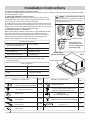
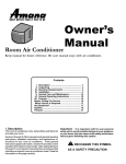
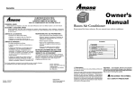
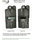
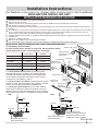
1. Check window opening size: the mounting parts
furnished with this air conditioner are made to install in
a wooden sill double-hung window. The standard parts
are for window dimensions listed above. Open sash to
DPLQLPXPRIƎPP),*
2. Check condition of window: all wood parts of window
must be in good shape and able to firmly hold the needed
VFUHZV,IQRWPDNHUHSDLUVEHIRUHLQVWDOOLQJXQLW
3. Check your storm windows:,I\RXUVWRUPZLQGRZ
IUDPHGRHVQRWDOORZWKHFOHDUDQFHUHTXLUHGFRUUHFWE\
DGGLQJDSLHFHRIZRRGDVVKRZQ),*RUE\UHPRYLQJ
storm window while room air conditioner is being installed.
FIG.1
side retainer
bottom rail
seal to unit
Ǝ long
screws and
ORFNQXWV
window
VXSSRUWEUDFNHW
ORFNQXWƎ
long flat
head bolt
frame
assembly
ULJKW
sill angle
EUDFNHW
FIG.2
sash
sash
ƎPLQ
ƎPLQ
ƎPLQ
ƎPLQ
ƎPLQ
inner sill
inner sill
outer sill
outer sill
storm window frame or
other obstruction
storm window frame or
other obstruction
ERDUGWKLFNQHVVDV
UHTXLUHGDORQJHQWLUHLQQHU
window sill; fasten to inner
sill with two nails or screws.
$
1
Installation Instructions
4. Check for anything that could block airflow
&KHFNDUHDRXWVLGHRIZLQGRZIRUWKLQJVVXFKDVVKUXEVWUHHVRUDZQLQJV,QVLGHEHVXUHIXUQLWXUHGUDSHVRUEOLQGV
will not stop proper air flow.
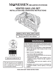
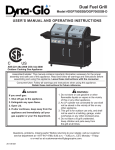
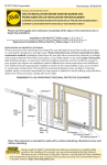
5. Check the available electrical service
WARNING
$YRLGILUHKD]DUGRUHOHFWULF
Power supply must be the same as that shown on the unit serial
VKRFN'RQRWXVHDQH[WHQVLRQFRUGRUDQ
nameplate. (See Use & Care Guide for serial plate location.) Power
DGDSWRUSOXJ'RQRWUHPRYHDQ\SURQJ
FRUGLVƎORQJ%HVXUH\RXKDYHDQRXWOHWQHDU
from the power cord.
$OOPRGHOVKDYHDSURQJVHUYLFHSOXJWRSURYLGHSURSHUVHUYLFHDQG
VDIHSRVLWLYHJURXGLQJ'RQRWFKDQJHSOXJLQDQ\ZD\'RQRWXVHDQ
DGDSWHUSOXJ,I\RXUSUHVHQWZDOORXWOHWGRHVQRWPDWFK\RXUSOXJFDOO
DTXDOLILHGHOHFWULFLDQWRPDNHWKHQHHGHGFKDQJH
6. Carefully unpack air conditioner
115V
5HPRYHDOOSDFNLQJPDWHULDO3URWHFWIORRURURWKHUVWDEOHIODWVXUIDFH
230V
230V
15A
ZLWKFRYHULQJWRSUHYHQWVFUDWFKHVIURPXQLW:LWKWKHDLGRIDQ
15A
20A
DVVLVWDQWUHPRYHXQLWIURPVW\URIRDPEDVHDQGUHVWRQSURWHFWHG
VXUIDFH0RYHDQGLQVWDOOXQLWZLWKWKHDLGRIDQDVVLVWDQW6DYH
SDFNLQJDQGVKLSSLQJER[IRUIXWXUHXQLWVWRUDJH
*URXQGLQJ3URQJ
$FFHVVRU\.LWLQFOXGHV
230V
30A
+DUGZDUHEDJVKLSSHGLQVLGH
window support brackets)
)RDPJDVNHW
:LQGRZVXSSRUWEUDFNHW
:LQGRZVDVKVHDO
6LGHUHWDLQHU
%RWWRPUDLOVHDO
:LQGRZ)LOOHU3DQHO
7RSDQJOHUDLO
Do not, under any
circumstances, cut,
remove or bypass the
grounding prong.
HEAVY DUTY
(22,000~28,500BTU)
0(',80PRGHOVRQO\
+($9<'87<WRSDQJOHUDLOFDQEHIRXQGLQFDUWRQEDVH
SDFNDJLQJ),*
FIG.3
723$1*/(5$,/
Tools Required
DODUJHIODWEODGHVFUHZGULYHU
tape measure
adjustable wrench or pliers
pencil
OHYHO
Socket wrenches
3KLOOLSVVFUHZGULYHU
+DUGZDUHLQSODVWLFEDJ
Ǝ/RFNLQJ6FUHZDQG)ODW
:DVKHUIRUZLQGRZILOOHUSDQHOV
HD
Ǝ/RQJKH[KHDGVFUHZ
7
6DIHW\/RFN
1
Ǝ/RQJ6FUHZ
and locknut
4 ea
Ǝ/RQJ)ODW+HDG%ROW
and Locknut
HD
foam insert
2
4W\
+DUGZDUHLQSODVWLFEDJ
6LOO$QJOH%UDFNHW
/RQJKH[KHDGORFNLQJVFUHZIRUWRS
DQJOHUDLOVLGHUHWDLQHUƎORQJ
6DIHW\/RFN
IRU9LQ\O&ODGZLQGRZ
/RFNLQJVFUHZ;Ǝpanhead
3KLOOLSVVFUHZVIRU9LQ\O&ODGZLQGRZ
weather seals
Ǝ;Ǝ;Ǝ
4W\
10
Installation Instructions
Window
1
Mounting
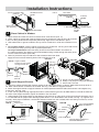
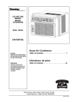
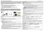
Remove Air Conditioner from Cabinet
NOTE: Remove any packaging material from cabinet exterior.
1. Pull down on front grille from upper edge. Lift front grille upwards and place to one side. (See FIG.1)
2. Remove filter. To remove, grasp in the middle on each side. Bow filter out to detach top edge from tabs. Once top
is free, lift filter up and out.
FIG.2
FIG.1
Front Grille
3. Locate the four Front Panel screws and remove. These screws will be needed to re-install the Front Panel later
(See FIG.2).
4. Push metal cabinet side inward to release plastic tabs on each side of Front Panel (see Fig. 3).
5. Rotate Front Panel up until top tabs are free. Pull panel straight out. When pulling out, front panel will also pull free
from vent control lever. Depress latch on electronics plug (on some models) to disconnect.
6. Remove Front Panel from unit (see Fig. 4).
FIG.3
FIG.4
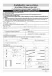
base pan handle
7. Remove shipping screws from top of unit and also on both sides by the base if installed. (See FIG.5)
8. With the aid of an assistant, hold the cabinet while pulling on the base pan handle (see FIG. 4), and carefully
remove the air conditioner from cabinet.
9. Add two foam inserts to holes in top of cabinet where shipping screws were removed from. (See FIG.6)
10. Except 22,000BTU model, other heavy duty models (24,000~28,500BTU) come with internal shipping packaging.
THIS PACKAGING AND PLASTIC TIES MUST BE REMOVED PRIOR TO INSTALLING THE AIR CONDITIONER
BACK INTO THE CABINET. (See FIG.7)
11. Remove plastic wrapping from all points on power cord.
FIG.7
FIG.5
shipping
Shipping Packaging
screws
FIG.6
2
Plastic tie
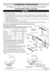
Install Top Angle Rail and Side Retainers
1. Remove adhesive strip coating from foam gasket. Attach adhesive side of gasket to bottom of top angle rail. Insert 4
screws from inside of cabinet and secure to top angle rail.
FIG.8
Top angle rail
2. From inside of cabinet insert 3 screws to attach each side retainer as shown
in Fig. 8. Attach side retainers with flat side against cabinet and angled edge toward
rear of cabinet.
3
Assemble Window Filler Panels
1. Place cabinet on floor, a bench, or a table.
2. Slide "I" section at end of window filler panel into side retainer on each side of the
cabinet (see FIG. 9 and FIG.10).
Foam Gasket
3. On each side of cabinet, insert top and bottom legs of window filler panel
frame into channel in the top and bottom angle rails.
4. Insert a 7/16" locking screw and flat washer into hole on top leg of each window filler panel (see section 6). Do not
totally tighten. Allow leg to slide freely. Screws will be tightened after Section 6.
3
Installation Instructions
),* TRSZLQGRZILOOHU
SDQHOOHJ
:,1'2:),//(5
P$1(/
),*
TOP9,(:
$,5&21',7,21(5
&$%,1(7
%RWWRPZLQGRZ
ILOOHUSDQHOOHJ
“I´6(&7,21
WINDOW
),//(5
P$1(/
6,'(5(TAINER
4
3/$67,&
)5$0(
Place Cabinet in Window
2SHQZLQGRZDQGPDUNWKHFHQWHURIZLQGRZLQQHUVLOODVVKRZQ),*1
3ODFHFDELQHWLQZLQGRZZLWKFDELQHWEUDFNHWVHFXUHO\VHDWHGRYHUHGJHRILQQHUVLOODVVKRZQ
LQ),*%ULQJZLQGRZGRZQWHPSRUDULO\EHKLQGWRSDQJOHUDLOWRKROGFDELQHWLQSODFH
6KLIWFDELQHWOHIWRUULJKWDVQHHGHGWROLQHXSFHQWHURIFDELQHWRQFHQWHUOLQHPDUNHGRQLQQHU
VLOO
For wooden window: )DVWHQFDELQHWWRZLQGRZLQQHUVLOOZLWKWZRORQJKH[KHDGVFUHZV
LQWRKROHV),*$YRXPD\ZLVKWRSUHGULOOSLORWKROHV
For Vinyl-Clad window: 3ODFHWZRVDIHW\ORFNVLQWRWKHKROHVORFDWHGLQWKHERWWRPRI
WKHFDELQHWDQGGULYHWZR;ƎSDQKHDG3KLOOLSVORFNLQJVFUHZVWKURXJKWKHVDIHW\ORFNV
LQWRWKHFDELQHWDVVKRZQ),*%
5HPRYHSURWHFWLYHVWULSIURPDGKHVLYHVLGHRI%RWWRP5DLO)RDP6HDO
$SSO\6HDORYHUVFUHZVIDVWHQLQJERWWRPUDLOWRZLQGRZLQQHUVLOO
A
FIG.13A
FIG.13B
FIG.12 $QJOHRIFDELQHW
%
FIG.11
ƎORQJ
HEX-HEAD
SCREW
EUDFNHWVHFXUHO\VHDWHG
RQHGJHRILQQHUVLOO
ZLQGRZ
LQQHUVLOO
/2&.,1*
6&5(:+2/(
FDELQHW
%UDFNHW
C
ZLQGRZ
RXWHUVLOO
$;ƎSDQKHDG3KLOOLSVVFUHZV
%6DIHW\/RFN2QO\IRU9LQO\&ODG:LQGRZ
&%RWWRP5DLO)RDP6HDO
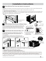
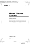
+ROGHDFKVXSSRUWEUDFNHWIOXVKDJDLQVWRXWVLGHRIVLOODQGWLJKWWRERWWRPRIFDELQHW0DUNEUDFNHWVDWWRSOHYHORI
VLOO0DUNFDELQHWERWWRPDWGLVWDQFHRIVLOOZLGWK6HH)LJ$5HPRYHVXSSRUWEUDFNHWV
$WWDFKVLOODQJOHEUDFNHWVWRVXSSRUWEUDFNHWVDWPDUNHGSRVLWLRQVZLWKIODWKHDGEROWVDQGQXWV+DQGWLJKWHQRQO\
DWWKLVSRLQW6HH)LJ%
,QVHUWORQJEROWVWKURXJKDSSURSULDWHKROHVLQFDELQHWERWWRPJLYHQWKHVLOOZLGWKGLVWDQFH7KUHDGWKHEROWVLQWR
WKHVORWVRIWKHVXSSRUWEUDFNHWVTLJKWHQORFNZDVKHUQXWVRQWREROWV
$GMXVWKHLJKWRIVLOODQJOHEUDFNHWVRWKDWEUDFNHWUHVWVVHFXUHO\RQHGJHRIVLOODQGVRWKDWFDELQHWKDVDERXWWR
GRZQZDUGWLOWIRUSURSHUZDWHUGUDLQDJHWLOWHGDERXWWRGRZQZDUGWRWKHRXWVLGHVHH)LJ7LJKWHQQXWV
VHFXUHO\$IWHUSURSHULQVWDOODWLRQFRQGHQVDWHVKRXOGQRWGUDLQIURPWKHRYHUIORZGUDLQKROHGXULQJQRUPDOXVHFRUUHFW
WKHVORSHRWKHUZLVH
FIG.15B
:LQGRZ6DVK
FIG.14
Ǝ/21*6&5(:6
5
Install Support Bracket
/()7
DERXWƎƎ
$1'/2&.1876
/2&.187
6,//$1*/(
%5$&.(7
6LGH/RXYHUV
6LOO$QJOH%UDFNHW
:LQGRZ6LOO
4
Ǝ/21*
SCREWS$1'
/2&.1876
0$5.
FIG.15A
0$5.
5,*+7
)/AT+($'%2/T
($&+5(4¶')25($&+
68332RT%5$&.(7
Installation Instructions
6
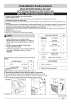
Extend Window Filler Panels and attach to top angle rail:
1. Carefully raise window to expose filler panel locking screws on top angle rail. Loosen screws so filler panels slide
easily.
2. Extend panels to fill window opening completely. Tighten locking screws on top (FIG. 16).
3. Close window behind top angle rail.
4. $WWDFKWKHWRSDQJOHUDLOWRZLQGRZIUDPH8VHDƎGULOOELWWRGULOORQHKROHWKURXJKWKHKROHLQWKHPLGGOHRIWRS
DQJOHUDLOLQWRWKHZLQGRZIUDPHDQGGULYHRQHƎHEX-HEAD locking screw through the hole in the middle of top
angle rail into the window frame as shown (FIG. 17).
FIG.16
FIG. 17
LOCKING SCREWS
ƎLocking Screw
and Washer
7
ƎORQJ
HEX-HEAD
SCREW
Attach Window Filler Panels to Window Frame
C
1. Extend the window filler panels out against the window frame.
2. Use a 1/8" drill bit to drill a starter hole through the hole in the
top leg of each window filler panel and into the window sash
(Fig. 18A and Fig. 18B). Connect with one 1/2" long hex head
screw.
8
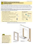
Install Window Sash Seal and Safety Lock
1. Trim window sash seal to fit window width. Insert it into
space between upper and lower sashes as shown (FIG. 19).
2. Attach right angle safety lock to top window sash as
shown (FIG.20).
3. If necessary, trim weather seals to needed length, peel
off protective backing, and use to plug any gaps. See Fig. 18B.
WINDOW
SASH SEAL
FIG. 18A
A
weather seals
Window Sash
B
A
A. Ǝlong hex head screw
B. left-hand Window Filler
Panel Top Leg
A. Ǝlong hex head screw
C. Window channel
FIG. 21
FIG.20
FIG.19
9
FIG. 18B
SAFETY LOCK
ƎORQJ
hex-head
screws
Vent control
correct location
Install Air Conditioner into Cabinet and Install Front Panel to Unit
1. Lift air conditioner and carefully slide into cabinet.
2. CAUTION: Do not push on controls OR finned coils.
3. Be sure air conditioner is firmly seated towards rear of cabinet.
4. Reconnect electronics plug if present. Position vent control lever so that it will thread into its channel in the front
panel (see FIG.21). Hook front panel top tabs into slots on cabinet top, and rotate front panel down so that side tabs
snap into place on cabinet. Insert 4 previously removed screws through front panel and into air conditioner.
5. Insert air conditioner filter. Reinstall the front grille by hooking bottom tabs into slots on Front Panel bottom, then
rotating grille up to snap into place.
5
Installation Instructions
Thru-The-Wall Installation
&RQVXOWORFDOEXLOGLQJFRGHVSULRUWRLQVWDOODWLRQRUDTXDOLILHGFDUSHQWHU
1
Select Wall Location
This air conditioner slides out from its cabinet, so that it can be installed through an outside wall as explained
below.
0D[ZDOOWKLFNQHVV
+HDY\GXW\
0HGLXP
Ǝ
Ǝ
NO
OTE:
IMPORTANT: Side louvers must never be blocked.
All parts needed for Thru-The-Wall Installation are provided, except a wood frame, shims, and 10 wood screws
ƎORQJPLQLPXP6HOHFWDZDOOVXUIDFHWKDW
'RHVQRWVXSSRUWPDMRUVWUXFWXUDOORDGVVXFKDVWKHIUDPHFRQVWUXFWLRQDWHQGVRIZLQGRZVDQGXQGHU
WUXVVEHDULQJSRLQWVHWF
'RHVQRWKDYHSOXPELQJRUZLULQJLQVLGH
,VQHDUH[LVWLQJHOHFWULFDORXWOHWVRUZKHUHDQRWKHURXWOHWFDQEHLQVWDOOHG
)DFHVWRWKHDUHDWREHFRROHGDQGLWLVQRWEORFNHG
$OORZVXQEORFNHGDLUIORZIURPUHDUVLGHVDQGHQGRXWVLGHRILQVWDOOHGDLUFRQGLWLRQHU
2
Prepare Wall
3UHSDUHZDOOLQIUDPHFRQVWUXFWLRQLQFOXGLQJEULFNDQGVWXFFRYHQHHU:RUNLQJIURPLQVLGHWKHURRPILQGZDOOVWXG
QHDUHVWWKHFHQWHURIDUHDZKHUHDLUFRQGLWLRQHUZLOOEHLQVWDOOHGE\VRXQGLQJZDOORUE\PDJQHWLFDOO\ILQGLQJQDLOV
&XWRXWDKROHRQHDFKVLGHRIFHQWHUVWXG
0HDVXUHEHWZHHQLQVLGHHGJHVRIHYHU\RWKHUVWXGDVVKRZQLQ),*&DUHIXOO\PHDVXUHDQGFXWDQRSHQLQJZLWK
WKHIROORZLQJGLPHQVLRQVGHSHQGLQJRQ\RXUPRGHO6HH),*DQG),*
:,'7+³;´ LQVLGHPRGHOZLGWKSOXVWZLFHWKHWKLFNQHVVRIIUDPLQJPDWHULDOXVHG
+(,*+7³<´ LQVLGHPRGHOKHLJKWSOXVWZLFHWKHWKLFNQHVVRIIUDPLQJPDWHULDOXVHG
&DSDFLW\
+HDY\'XW\
0HGLXP
22,000~28,500BTU
15,000~18,500BTU
,QVLGH)UDPH+HLJKW
ƎFP
ƎFP
,QVLGH)UDPH:LGWK
ƎFP
ƎFP
FIG.1
FIG.2
Y
Ǝ0,1
FP
Inside
)UDPH
+HLJKW
Inside
)UDPH
Width
X
8372Ǝ
6
Installation Instructions
4. Build a wooden frame with the INSIDE dimensions of your model listed above. (Measure twice remember...) Frame
depth should be the same as wall thickness. Fill in the space from the opending to the studs with wood spacers, as
shown.
5. Nail frame to spacers to spacers with front flush with dry wall.
NOTE:
If wall thickness is 8-1/2” or more, add alumimum flashing over bottom of frame opening to assure no water can
enter area between inner and outer wall.
NAIL SPACERS
TO STUDS
FIG.3
FIG.4
CAULK AS
REQUIRED
LEVEL
ALUMINUM FLASHING
OVER BOTTOM OF FRAME
29(5Ǝ
3
Prepare and Install Cabinet
1. Slide air conditioner from cabinet; refer back to Step 1 of Window Mounting.
2. Place cabinet into opening with bottom rail resting firmly on bottom board of wooden frame.
3. Position cabinet to achieve proper downward tilt for water removal. Unit must tilt back about 7/8" to 1 1/4" for proper
water drainage. (See FIG.5 below.)
6HFXUHERWWRPUDLOWRZRRGIUDPHZLWKWZRODUJHZRRGVFUHZVƎFPORQJXVLQJWKHWZRKROHVLQWKHERWWRPRI
the channel resting on frame. (See FIG.6 following)
FIG.5
FIG.6
DERXWƎƎ
Ǝ/21*
WOOD SCREW
Side Louvers
Refer to Step 5 of Window Mounting for assembly of support brackets. Nail a wooden strip to the outside wall for the
angle sill bracket to rest upon. See Fig. 7.
5. Screw or nail cabinet to wooden frame using shims as needed to eliminate cabinet distortion. See Fig. 8. Remember
to maintain proper tilt as described in Step 3.
7
Installation Instructions
FIG.7
FIG.8
Support bracket
Sill angle bracket
Wooden strip
6. Install air conditioner into cabinet by following all steps in Step 9 of Window Mounting.
OPTIONAL: Caulking and installation of trim on interior wall may be done. You can buy wood from your local lumber or
hardware supply. On the outside, caulk opendings around top and sides of cabinet, and all sides of wood sleeve to the
opening.
NOTE:
See Step 5, Item 4 of Window Mounting Instructions for bottom rail seal location.
Masonry Construction
1. Cut or build a wall opening in the masonry wall similar to the frame construction (refer to Step 2 of Thru-the-Wall
,QVWDOODWLRQIRUDZDOOWKLFNQHVVJUHDWHUWKDQƎ
2. Secure cabinet in place using masonry nails, or the right masonry anchor screws. (Another way to secure cabinet is
to build a frame in the masonry wall such as the one shown in Fig. 3 of Step 2 Prepare Wall. Securely anchor frame to
PDVRQU\ZDOO7KLVZD\JLYHVYHU\JRRGORXYHUFOHDUDQFHRQHLWKHUVLGHRIFDELQHW
3. Install a lintel to support masonry wall above cabinet. Existing holes in cabinet can be used and/or additions holes
can be drilled to fasten cabinet at various positions. Be sure that side louver clearance is in accordance with Step 1
Select Wall Location.
4. Install exterior cabinet support brackets as shown in Step 3 of Thru-the-Wall Installation. Caulk or flash if needed, to
provide a weather-tight seal around top and sides of cabinet.
5. To complete installation, apply wood trim molding around room side projection of cabinet.
8