1
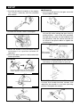
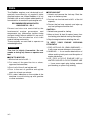
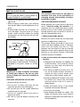
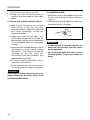
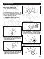
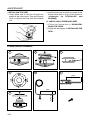
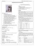
5850-93110 (9809) OWNER / OPERATOR MANUAL TRIMMERS / STICK EDGERS BT2200LDC BC2200E BC2200LDC HE2200LDC BT2200LDC BC2200E BC2200LDC WARNING The engine exhaust from this product contains chemicals known to the State of California to cause cancer, birth defects or other reproductive harm. HE2200LDC IMPORTANT : Before operating your RedMax product, read this manual carefully and completely. Thank you for choosing a RedMax trimmer / stick edger. This manual will provide you with full understanding of the necessary instructions for assembly, operation and maintenance of the equipment. Please read this manual carefully before starting operation. For continued safe and reliable operation, use ONLY original RedMax parts and accessories, Adhere to all notes and warnings. CONTENTS FOR SAFE OPERATION · · · · · · · · · · · · · · · · · · · · · · 2 SETUP · · · · · · · · · · · · · · · · · · · · · · · · · · · · · · · · · · · · 3 FUEL · · · · · · · · · · · · · · · · · · · · · · · · · · · · · · · · · · · · · · 4 OPERATION · · · · · · · · · · · · · · · · · · · · · · · · · · · · · · · · 5 MAINTENANCE · · · · · · · · · · · · · · · · · · · · · · · · · · · · · 9 SPECIFICATIONS · · · · · · · · · · · · · · · · · · · · · · · · · · 13 PARTS LIST · · · · · · · · · · · · · · · · · · · · · · · · · · · · · · · 14 FOR SAFE OPERATION ■ KNOW YOUR UNIT 1. Read this Owner's Manual carefully until you completely understand and can follow all safety rules, precautions, and operating instructions before operating the unit. 2. Restrict your unit to users who understand and follow all safety rules, precautions, and operating instructions found in this manual. Children should not be allowed to operate this unit. ■ PLAN AHEAD 1. Dress in a long-sleeved shirt and long pants. Wear protective gloves and shoes. Eye and ear protection should be worn at all times. Do not wear loose clothing, jewelry, short pants or sandals. Do not go barefoot. 2. Guard against hazardous situations at all times. Warn adults to keep pets and children away from the work area. Establish a safe method for gaining your attention during operation. Be careful if you are approached. 3. Do not operate the unit when you are tired, ill or upset; or if you are under the influence of alcohol, drugs, or medication. 4. Inspect the work site before each use. Remove all debris and objects that could be thrown, become entangled in the cutting head, or cause damage during operation. ■ HANDLE FUEL WITH CAUTION 1. Eliminate all sources of sparks or flame (including smoking, open flames, or work that could cause sparks) in the area where fuel is mixed, poured, or stored. 2. Mix, pour, and store fuel in an approved, marked container and in a well ventilated area. 3. Be sure to stop the engine before refueling the unit. 4. Do not smoke while handling fuel or while operating the unit. 5. Wipe up all spills before starting the engine. Move at least 10 feet (3 meters) away from fuel and refueling site before starting the engine. 2 ■ OPERATE YOUR UNIT SAFELY 1. Inspect the entire unit before each use for worn, loose, or damaged parts. Do not use until the unit is in proper working order. 2. Keep the handles free of oil and fuel. 3. Never start or run the engine inside a closed room or building, Exhaust fumes contain dangerous carbon monoxide. 4. Keep the engine idle speed adjusted properly so that the cutting head comes to a complete stop when trigger is released. 5. Be sure to stop the engine before refueling, inspecting or leaving the unit unattended. 6. A lw a y s use both hands to hold the unit. 7. Do not use any accessory or attachment other than those bearing the RedMax mark and are recommended for the unit. ■ MAINTAIN YOUR UNIT PROPERLY 1. Disconnect the spark plug before performing all maintenance except for carburetor adjustment. 2. Use only recommended, genuine replacement parts to avoid creating hazard and/or voiding your warranty. 3. Wear protective gloves when handling or performing maintenance on metal blades. 4. When transporting or storing the unit, drain fuel from the fuel tank. 5. Do not store the unit or fuel in a closed area where fuel vapors can reach an open flame from hot water heaters, furnaces, and so on. 6. Store the unit in a dry area out of the of children. 7. All engine service, other than those explained in this manual, should be performed by competent service personnel. Improper service to the muffler and flywheel could cause serious accidents, resulting in bodily injury. SETUP 1. Install the driveshaft assembly to the engine unit. Clamp it securely with the attached bolt and nut. ■ HE2200LDC 1. Install the blade guard to the gear case with the provided 3 screws. HE2200LDC 2. Connect the throttle cable to the engine. 2. Place the blade between the cutter holders (A) and (B) while locking the gear shaft by putting the bar , one of the tools provided, through the key holes on the holder(A) and the gearcase. Use the socket and the bar as shown in the picture below to tighten the mounting nut. 3. Mount the handle to the driveshaft casing and clamp it at a position suitable for operation. 4. Install the debris guard to the bracket with screws provided. BT2200LDC 3. Install the J-shaped handle to the shaft tube and clamp at a position best for your job. Attach the guard above the clamp and slide it down. Rotate it a half turn to set in place. BC2200E • ADJUSTING HANDLE POSITION Loosen the handle bracket screws and reposition the handle to your best operating position. Re-tighten the screws. BC2200LDC 3 FUEL The RedMax engines are lubricated by oil specially formulated for air-cooled 2-cycle gasoline engine use. When RedMax oil is not available, use an anti-oxidant added quality oil formulated for air-cooled 2-cycle engine use. RECOMMENDED MIXING RATIO GASOLINE 32 : OIL 1 Exhaust emission are controlled by the fundamental engine parameters and components (eq., carburation, ignition timing and port timing) without addition of any major hardware or the introduction of an inert material during combustion. These engines are certified to operate on unleaded gasoline. WARING!!! The fuel is highly flammable. Do not smoke or bring any flame or sparks near fuel. ■ HOW TO MIX FUEL 1. Mix the fuel and oil at 32 : 1 2. Put some of the gasoline into a clean, approved fuel container. 3. Pour in all of the oil and agitate well. 4. Pour in the rest of gasoline and agitate again for at least one minute. 5. Put a clear indication on the outside of the container to avoid mixing up with gasoline or other containers. 4 ■ FUELING UNIT 1. Untwist and remove the fuel cap. Rest the cap on a dustless place. 2. Put fuel into the fuel tank to 8O% of the full capacity. 3. Fasten the fuel cap securely and wipe up any fuel spillage around the unit. CAUTION : 1. Select bare ground for fueling. 2. Move at least 10 feet (3 meters) away from the fueling point before starting the engine. 3. Stop the engine before refueling the unit. TO KEEP YOUR EFFICIENTLY ENGINE WORKING 1. FUEL WITH NO OIL (RAW GASOLINE) — It will cause severe damage to the system. 2. GASOHOL — It can cause deterioration of rubber and/or plastic parts and disruption of engine lubrication. 3. OIL FOR 4-CYCLE ENGINE USE or WATER COOLED 2-CYCLE ENGINE USE — It can cause spark plug fouling, exhaust port blocking, or piston ring sticking. OPERATION ■ STARTING ENGINE WARING!!! Keep the cutting head off the ground and clear of surrounding objects as it will start rotating upon starting of the engine. 1. Press the primer bulb until fuel flows out in the clear tube (5 to 7 times). Lace the choke lever in the full choke position. When restarting the engine right after stopping it, keep the choke open. 2. Put the ignition switch in the "ON" position. NOTE : Avoid pulling the rope to its dead end or returning it by releasing the knob. Such actions can cause starter failures. 4. When the engine has started, move the choke lever gradually upward to open choke. 5. Allow the engine to warm up for a half minute before starting operation. NOTE : 1. When restarting the engine immediately after stopping it, leave choke open. 2. Overchoking can make the engine hard to start due to excess fuel. When the engine fails to start after several attempts, open choke and repeat pulling the rope or remove the spark plug and dry it. ■ STOPPING ENGINE 1. Release the throttle trigger and run the engine for a half minute. 2. Put the ignition switch in the "OFF" position. NOTE : Except for an emergency, avoid stopping the engine while the trigger is on. ■ ADJUSTING IDLING SPEED 1. When the engine tends to stop frequently at idling mode, turn the adjusting screw clockwise. Idling speed : 2800rpm 3. Rest the unit on a flat, firm place. While pulling the throttle trigger with the little finger of your left hand, pull the starter rope quickly. 2.When the cutting head keeps rotating after releasing the trigger, turn the adjusting screw counter clockwise. NOTE : Warm up the engine before adjusting the idling speed. 5 OPERATION ■ LINE HEAD USAGE • HOW TO USE WARING!!! 1. Always wear eye protection such as safety goggles. Never lean over the rotating cutting head. Rocks or other debris could be thrown into eyes and face and cause serious personal Injury. 2. Keep the debris guard attached in place at all times when the unit is operated. • TRIMMING GRASS AND WEEDS Always remember that the TIP of the line does cutting. You will achieve better results by not crowding the line into the cutting area. Allow the unit to trim at its own pace. 1. Hold the unit so the cutting head is off the ground and tilted about 30 degrees toward the sweep direction. 2. Use full throttle when cutting. 3. You can avoid thrown debris by sweeping in the correct direction, I.e., from your right to the left for BT2200LDC & BC2200E, and from your left to the right for BC2200LDC. 4.Use a slow, deliberate action to cut heavy growth. The rate of cutting motion will depend on the material being cut. Heavy growth will require slower action than will light growth. 5.Never swing the unit too hard because you may lose your balance or control of the unit. 6.Try to control the cutting motion with the hip rather than placing the full workload on the arms and hands. 7.Take precautions to avoid wire, grass and dead, dry, long-stem weeds from wrapping around the cutting head shaft. Such materials can stall the cutting head and cause the clutch to slip, resulting in damage to the clutch system, if repeated frequently. 6 • ADJUSTING LINE LENGTH Your trimmer is equipped with a bump head that allows the operator to advance the line without stopping the engine. When the line becomes short, lightly tap the head on the ground while running the engine at full throttle. Each time the head is bumped, the line advances about 1 inch (25.4 mm). For best results, tap the head on bare ground or hard soil. If line release is attempted in tall grass, the engine may stall. NOTE : Always keep the trimming line fully extended. Line release becomes difficult as the cutting line becomes shorter. OPERATION ■ METAL BLADE USAGE NOTE : Do not use the Metal Cutting Blade for model BT2200LDC and BC2200E • Always cut by guiding the head from your right to left. • When mowing a wide area, start working from the left side to avoid interference of cut grass. • A metal blade cuts best up to the point 1/3 from the edge. Use that area for cutting shrubs, tough and thick weeds. For cutting young grass, you can use up to 2/3 from the tip of blade. Never cut with this side Tough weeds Young grass Note : Do not use the Metal Cutting Blade for cutting trees or thick branches. The blade is designed to cut grass, weeds or shrubs only. WARING!!! Working on a slope increases the danger of losing your balance. Do not use your unit on a slope until you have mastered its operation. FOR SAFE OPERATION ON A SLOPE: 1. Always use anti-slip shoes. 2. Do not work in and/or right after the rain when the ground is wet and slippery. 3. Do not use your unit on a slope where firm footholds are not secured. 4. Do not cut material above your waist or below your ankle. 5. Be sure to stop the engine moving to the next row. WARING!!! The operator must keep his own path of advance clear due to the possibility of swinging around and seriously injuring a bystander or helper. CONTROLLING BLADE BOUNCE Blade bounce can cause serious personal injury. Carefully study this section. It is important that you understand what causes bounce, how you can reduce the chance of bounce and how you can remain in control of the unit if bounce does occur. 1. What causes blade bounce: Bounce can occur when the moving blade contacts an object that it cannot cut. This contact causes the blade to stop for an instant and then suddenly move or “bounce” away from the object that was hit. The operator can lose control of the unit and the blade can cause serious personal injury to the operator or any person nearby if the blade contacts any part of the body. 2. How you can reduce the chance of blade bounce: a. Recognize that bounce can happen. By understanding and knowing about bounce, you can help eliminate the element of surprise. b. Cut fibrous weeds and grass only. Do not let the blade contact materials it cannot cut such as hard, woody vines and brush or rocks, fences, metal, etc. c. Be extra prepared for bounce if you must cut where you cannot see the blade making contact such as in areas of dense growth. d. Keep the blade sharp. A dull blade increases the chance of bounce. e. Cut only at full throttle. f. Avoid feeding the blade too rapidly. The blade can bounce away from material being cut if the blade is fed faster than its cutting capability. 7 OPERATION g. Cut only from your right to your left. TO SHARPEN BLADE : h. Keep your path of advance clear of material that has been cut and other debris. 1. Grind away each cutting edge and its back evenly and maintain similar shape to original. 3. How you can maintain the best control: a. Keep a good, firm grip on the unit with both hands. A firm grip can help neutralize bounce. Keep your right and left hands completely around the respective handles. b. Keep both feet spread apart in a comfortable stance and yet braced for the possibility that the unit could bounce. Do not overreach. Keep firm footing and balance. c. Always use the shoulder harness. Adjust the harness for comfort before starting the engine. The harness should be adjusted so the left hand can comfortably hold the handlebar grip approximately waist high. d. Do not cut material waist high or over to avoid loss of unit control. e. Do not swing the unit with such force that you are in danger of losing your balance. WARING!!! Stop engine before removing grass or weed wrappings to avoid injury from accidental blade rotation. 8 2. Sharpen each cutting edge and make sure the bottom corner is rounded. .10"R .15"R WARING!!! • If edge bottom is finished square, the blade will tend to crack from the corner during operation. • Do not cool the blade with water in case of using grinder. It may cause cracks on blade. MAINTENANCE I. Bump head for BT2200LDC and BC2200E ■ REPLACING TRIMMING LINE To refill a new trimming line either ; A : Install the prewound reel #153577 or B : Rewind the existing reel. For replacement line, use a diameter of .080 in (2.03 mm). The engine may overheat and fail if you use a larger line. For safety reason, do not use metal-reinforced line. A : REWINDING THE EXISTING SPOOL • DISASSEMBLING THE HEAD 1. Hold the outer spool with one hand and unscrew the Bump Knob bolt (counterclockwise for BT2200LDC and BC2200E). Inspect the captured bolt inside the Bump Knob to make sure it moves freely. Replace the Bump Knob if it is damaged. • WINDING NEW LINE 1. Take 25 ft (7.6 m) of new trimming line, insert one end through either hole on the inner reel and put the other end through another hole. Hold the line where the both ends are matching and pull it to make the loop as small as possible. BT2200LDC BC2200E 2. Wind the line in the direction indicated on the inner reel, in even and tight layers. Be sure not to overlap the two ends of the line. 2. Remove the inner reel. Use a clean cloth to clean the inner reel, the inside of the outer spool and the center shaft. 3. Insert each end of the line into the holding slot. 3. Inspect the indexing teeth on the inner reel and outer spool for wear and, if necessary, deburr or replace the reel and spool. 9 MAINTENANCE • INSTALLING THE REEL 1. Insert each end of the line through the eyelet on the outer spool. Then pull the end firmly to release the line from the holding slot. 2. Hold the inner reel in place and screw in the Bump Knob bolt in the correct direction (clockwise for BT2200LDC and BC2200E). B : INSTALLING A PREWOUND REEL 1. Follow the instructions in DISASSEMBLING THE HEAD. 2. Follow the instructions in INSTALLING THE REEL. II. Bump head for BC2200LDC 1 4 6 2 5 7 3.8m (12.5') Ø2.4mm 0.095In 3 7.6m (25') 10 MAINTENANCE 8 11 14 THIS SIDE UP WIND LINE 1 2 9 10 12 THIS SIDE UP 15 13 11 MAINTENANCE ■ AIR FILTER The air filter, if clogged, will reduce the engine performance. Every 30 days, check and clean the filter element in warm, soapy water as required. Dry completely before installing. If the element is broken or shrunk, replace with a new one. ■ SPARK PLUG Starting failure and mis-firing are often caused by a fouled spark plug. Periodically clean the spark plug and check that the spark gap is within the correct range. For a replacement plug, use Champion RCJ6Y or the equivalent. ■ FUEL FILTER When the engine runs short of fuel supply, check the fuel filter for blockage. ■ STORAGE Old fuel left in the carburetor may cause starting failure. Before storing the unit, empty the fuel tank and start the engine and run it on until it stops by itself. 12 SPECFICATIONS ■ BT2200LDC Overall size (LxWxH) ···························································································62.2x9.7x17.9 (in) Dry weight ·························································································································10.1 (lbs) Engine Type ························································································Air-cooled 2-stroke gasoline Model ············································································································Zenoah G22L Displacement ·······································································································22.5 (cc) Max. output ························································································0.9 (HP) at 7000 rpm Idling speed ·········································································································2800 rpm Operating speed (with standard head) ·································································8300 rpm Fuel ·························································································Mixture (Gasoline 32 : Oil 1) Fuel tank capacity ···············································································································20 (fl.oz) Transmission·Centrifugal clutch,Flex.driveshaft Reduction ratio ·································No reduction Cutting head rotating direction ·······························································Clockwise (Operator view) ■ BC2200E Overall size (LxWxH) ···························································································67.3x9.7x13.8 (in) Dry weight ·························································································································10.6 (lbs) Engine Type ························································································Air-cooled 2-stroke gasoline Model ·············································································································Zenoah G22L Displacement ········································································································22.5 (cc) Max. output ························································································0.9 (HP) at 7000 rpm Idling speed ·········································································································2800 rpm Operating speed (with standard head) ·································································7600 rpm Fuel ·························································································Mixture (Gasoline 32 : Oil 1) Fuel tank capacity ···············································································································20 (fl.oz) Transmission·Centrifugal clutch,Flex.driveshaft Reduction ratio ···············································1.00 Cutting head rotating direction ································································Clockwise (Operator view) ■ BC2200LDC Overall size (LxWxH) ·························································································68.5x10.2x13.2 (in) Dry weight ··························································································································11.8 (lbs) Engine Type ························································································Air-cooled 2-stroke gasoline Model ·············································································································Zenoah G22L Displacement ········································································································22.5 (cc) Max. output ························································································0.9 (HP) at 7000 rpm Idling speed ·········································································································2800 rpm Operating speed (with standard head) ·································································7000 rpm Fuel ·························································································Mixture (Gasoline 32 : Oil 1) Fuel tank capacity ···············································································································20 (fl.oz) Transmission·Centrifugal clutch,Flex.driveshaft Reduction ratio ···············································1.23 Cutting head rotating direction ···················································Counter clockwise (Operator view) ■ HE2200LDC Overall size (LxWxH) ·························································································63.6x16.7x14.2 (in) Dry weight ·························································································································12.6 (lbs) Engine Type ························································································Air-cooled 2-stroke gasoline Model ·············································································································Zenoah G22L Displacement ········································································································22.5 (cc) Max. output ························································································0.9 (HP) at 7000 rpm Idling speed ·········································································································2800 rpm Operating speed (with standard blade)·····················································7000~11000 rpm Fuel ·························································································Mixture (Gasoline 32 : Oil 1) Fuel tank capacity ···············································································································20 (fl.oz) Transmission·Centrifugal clutch,Flex.driveshaft Reduction ratio ···············································1.23 Cutting head rotating direction ···················································Counter clockwise (Operator view) 13 PARTS LIST Fig.1 TRIMMER UNIT FOR BT2200LDC Fig.1 TRIMMER UNIT FOR BT2200LDC Key# Description Part Number Q'ty Key# Description Part Number Q'ty Curved shaft ass'y ————— 1 17 Guard mount screw 153318 1 2 Flex.drive shaft ————— 1 18 Guard ass'y 683445 1 3 Throttle housing ass'y 181125 1 19 Blade ass'y 682061 1 4 Throttle lever 180975 1 20 Anti-rotation screw 145569 1 5 Screw 145569 1 21 Spool shaft 153313 1 6 Screw 147544 5 22 Outer spool ass'y 153619 1 7 Spring 610314 1 23 Eyelet 145566 2 8 Handle ass'y 6462-14100 1 24 Retainer (10 pack) 610660 1 9 Handle 6462-14310 1 25 Spring 610317 1 10 Clamp 6462-14320 1 26 Inner reel 153600 1 11 Screw 0263-90535 4 27 Bump head knob ass'y 153066 1 12 Cutting head ass'y 147823 1 28 Throttle cable comp. 6502-82100 1 13 Lower clamp ass'y 153597 1 29 Decal ————— 1 14 Retaining ring 145570 1 15 Washer 145567 1 16 Bushing ass'y 153312 1 1 14 Fig.2 TRIMMER UNIT FOR BC2200E Fig.2 TRIMMER UNIT FOR BC2200E Key# Description Part Number Q'ty Key# Description Part Number Q'ty 1 Straight shaft ass'y ————— 1 16 Clamp assembly 2 Flex drive shaft ————— 1 17 Screw, Anti-rotation 145569 1 3 Throttle housing ass'y 181125 1 18 153619 1 4 Throttle lever 180975 1 Spool, Outer w/eyelet (include item 20) 5 Spring 610314 1 19 Eyelet 145566 1 6 Screw 145569 1 20 Retainer 610660 1 Spring 610317 1 153597 1 7 Screw 147544 5 21 8 Handle ass'y 6462-14100 1 22 Reel, inner 153600 1 9 Handle 6462-14310 1 23 Bump head knob assembly 153066 1 10 Clamp 6462-14320 1 24 Throttle cable comp 6502-82100 1 25 Decal ————— 1 11 Screw 0263-90535 4 12 Gear box ass'y 180549 1 13 Guard, Cutting head (include item 14) 180548 1 14 Blade assembly 180553 1 15 Heardware, guard mounting 180547 1 15 Fig.3 TRIMMER UNIT FOR BC2200LDC Fig.3 TRIMMER UNIT FOR BC2200LDC Key# Description 1 Straight shaft ass'y ————— 1 18 Housing UBTR-06 1 2 Flex.drive shaft ————— 1 19 Eyelet UBT-9 2 3 Gear box ass'y 1 1 NUT UBTR-F10 1 Screw 147488 ————— 20 4 21 Spring UBT-4 1 5 Screw set 147677 1 22 Spool UBT-3 1 6 Blade driver 147489 1 23 Button UBT-2 1 7 Lower retaining washer 147490 1 24 Cover UBT-1 1 8 Throttle housing ass'y 181125 1 25 Guard ass'y 6778-24000 1 9 Part Number Q'ty Key# Description Part Number Q'ty Throttle lever 180975 1 26 Guard Comp. 6778-24100 1 Screw 145569 1 27 Blade 6778-24140 1 11 Screw 147544 5 28 Screw 0263-30512 2 12 Spring 610314 1 29 Nut 3320-15310 2 13 Handle ass'y 6462-14100 1 30 Clamp 3541-24121 1 14 Handle 6462-14310 1 31 Bolt 3540-24130 2 15 Clamp 6462-14320 1 32 Washer 0290-20615 2 16 Screw 0263-90535 4 33 Throttle cable comp. 1 17 Cutting head ass'y UBT-200 1 34 Decal 6502-82100 ————— 10 16 1 Fig.4 STICK EDGER UNIT FOR HE2200LDC Fig.4 STICK EDGER UNIT FOR HE2200LDC Key# Description Part Number Q'ty Key# Description Part Number Q'ty Curved shaft ass'y ————— 1 17 Retaining washer 613222 1 2 Flex drive shaft ————— 1 18 Retaining nut 613221 1 3 Throttle housing ass'y 181125 1 19 Guard Ass'y 6779-24100 1 4 Throttle lever 180975 1 20 Plate, rubber 6779-24120 1 5 Spring 610314 1 21 Plate 6779-24130 1 6 Screw 145569 1 22 Bolt 00225-30512 2 7 Screw 147544 5 23 Mounting Bolt assambly set 684070 1 8 Handle bracket ass'y 683295 1 24 Guide bracket 6779-24150 1 9 Srew ————— 1 25 Wheel 613216 1 10 Tube closure 612021 2 26 Wheel mounting bolt ass'y 684068 1 11 Grip 612381 1 27 Adjustment knob set 684069 1 12 J-Handle ass'y 180687 1 28 Throttle cable 6502-82100 1 13 Gear box ass'y 147488 1 29 Decal ————— 1 14 Screw ————— 1 15 Driver, blade 613217 1 16 Blade 180064 1 1 17 Fig.5 ENGINE GROUP FOR BT2200LDC. BC2200E. BC2200LDC. HE2200LDC 18 Fig.5 ENGINE GROUP FOR BT2200LDC. BC2200E. BC2200LDC.HE2200LDC Key# Description Part Number Q'ty Key# Description Part Number Q'ty 1 2 3 4 5 6 7 8 Cylinder Gasket, base Bolt Insulator Gasket, insulator Gasket, carburetor Screw Muffler ass'y 5850-12110 5500-12211 1850-12130 5850-13160 5850-13120 5850-13130 5850-13210 5850-15100 1 1 2 1 1 1 2 1 5850-15140 5850-15130 5850-15211 5850-15220 5850-15230 5850-21100 5500-21140 06030-06001 2169-21210 1850-21220 04065-02812 01252-30530 5600-41111 1100-41210 1101-41310 1260-41320 5850-42000 1000-43240 5850-51100 5850-51210 5850-51220 5850-71111 5850-71200 1260-71261 5850-72160 5850-75100 5850-75110 5850-75120 5850-75130 5850-75140 1400-86280 5850-75150 5850-75160 5850-75200 5850-75220 5850-75230 0308-00040 5850-15230 5850-83221 5850-81000 5850-81110 1 2 1 1 1 1 1 2 1 1 1 4 1 2 1 2 1 1 1 1 1 1 1 2 2 1 1 1 1 1 1 1 1 1 1 1 1 4 1 1 2 51 52 53 54 55 56 57 58 59 60 61 62 63 64 65 66 67 68 69 70 71 72 73 74 75 76 77 78 79 80 81 82 83 84 85 86 87 88 89 90 91 92 93 94 Ring Swivel Valve ass'y O-Ring Jet Diaphragm Gasket, pump Diaphragm, pump Body, pump Screen Gasket, diaphragm Body, purge Pump, priming Cover, pump Screw Screw O-Ring Body ass'y Sleeve Plate, choke Lever, choke Screw Element Cover Housing comp Bolt Nut Screw Cover, engine Screw Screw Spark plug Switch comp Tank Cap ass'y Pipe, Return Grommet Filter ass'y Screw Label, recoil Tool set Socket Bar Bar 1751-81130 1881-81140 ————— 1751-81240 5516-81250 3310-81260 1065-81410 1065-81420 1850-81450 3306-81380 1850-81470 1850-81490 1751-81510 1850-81520 1850-81530 5850-82310 5850-83110 5850-82100 ————— ————— ————— ————— 5850-82170 5850-82210 5850-31100 0225-30635 0280-10605 5850-13210 5850-32110 5850-15230 5850-32170 5602-73110 5850-72210 5850-85110 5850-85200 5850-85320 5850-85330 5850-85400 5850-85510 5850-91120 5850-91000 3239-91310 3582-91330 3540-91110 1 1 1 1 1 1 1 1 1 1 1 1 1 1 4 2 1 1 2 1 1 1 1 1 1 1 1 4 1 1 2 1 1 1 1 1 1 1 3 1 1 1 1 1 10 11 12 13 14 15 16 17 18 19 20 21 22 23 24 25 26 27 28 29 30 31 32 33 34 35 36 37 38 39 40 41 42 43 44 45 46 47 48 49 50 Arrester Screw Gasket, muffler Plate, muffler Screw Crankcase comp Gasket, case Bearing Oil seal Oil seal Snap ring Screw Piston Ring Pin Snap Ring Crankshaft comp Key Shoe-c Washer Spacer Rotor Coil ass'y Spacer Screw Recoil ass'y Case comp. Reel Spring, spiral Screw Washer Rope Knob Pulley ass'y Ratchet Spring Ring Screw Bracket Carburetor ass'y Screw 19 CALIFORNIA EMISSION CONTROL WARRANTY STATEMENT YOUR WARRANTY RIGHTS AND OBLIGATIONS THE CALIFORNIA AIR RESOURCES BOARD AND KOMATSU ZENOAH Co. ARE PLEASED TO EXPLAIN THE EMISSION CONTROL SYSTEM WARRANTY ON YOUR 1995 AND LATER LAWN AND GARDEN EQUIPMENT ENGINE. IN CALIFORNIA, NEW UTILITY AND LAWN AND GARDEN EQUIPMENT ENGINES MUST BE DESIGNED, BUILT AND EQUIPPED TO MEET THE STATE'S STRINGENT ANTI-SMOG STANDARDS. KOMATSU ZENOAH Co, MUST WARRANT THE EMISSION CONTROL SYSTEM ON YOUR LAWN AND GARDEN EQUIPMENT ENGINE FOR THE PERIODS OF TIME LISTED BELOW PROVIDED THERE HAS BEEN NO ABUSE, NEGLECT OR IMPROPER MAINTENANCE OF YOUR LAWN AND GARDEN EQUIPMENT ENGINE. YOUR EMISSION CONTROL SYSTEM. MAY INCLUDE PARTS SUCH AS THE CARBURETOR, THE IGNITION SYSTEM, AND CATALYTIC CONVERTER. ALSO INCLUDED MAY BE THE HOSES, BELTS, CONNECTORS AND OTHER EMISSION-RELATED ASSEMBLIES. WHERE A WARRANTABLE CONDITION EXISTS, KOMATSU ZENOAH Co. WILL REPAIR YOUR LAWN AND GARDEN EQUIPMENT ENGINE AT NO COST TO YOU INCLUDING DIAGNOSIS, PARTS AND LABOR. MANUFACTURER'S WARRANTY COVERAGE: THE 1995 AND LATER UTILITY AND LAWN AND GARDEN EQUIPMENT ENGINES ARE WARRANTED FOR TWO YEARS. IF ANY EMISSION-RELATED PART ON YOUR ENGINE IS DEFECTIVE, THE PART WILL BE REPAIRED OR REPLACED BY KOMATSU ZENOAH Co. OWNER'S WARRANTY RESPONSIBILITIES: —AS THE LAWN AND GARDEN EQUIPMENT ENGINE OWNER, YOU ARE RESPONSIBLE FOR THE PERFORMANCE OF THE REQUIRED MAINTENANCE LISTED IN YOUR OWNER'S MANUAL. KOMATSU ZENOAH Co. RECOMMENDS THAT YOU RETAIN ALL RECEIPTS COVERING MAINTENANCE ON YOUR LAWN AND GARDEN ENGINE, BUT KOMATSU ZENOAH Co. CAN NOT DENY WARRANTY SOLELY FOR THE LACK OF RECEIPTS OR FOR YOUR FAILURE TO ENSURE THE PERFORMANCE OF ALL SCHEDULED MAINTENANCE. —AS THE LAWN AND GARDEN EQUIPMENT ENGINE OWNER, YOU SHOULD BE AWARE, HOWEVER, THAT KOMATSU ZENOAH Co. MAY DENY YOU WARRANTY COVERAGE IF YOUR LAWN AND GARDEN EQUIPMENT ENGINE OR A PART HAS FAILED DUE TO ABUSE, NEGLECT, IMPROPER MAINTENANCE OR UNAPPROVED MODIFICATION. —YOU ARE RESPONSIBLE FOR PRESENTING YOUR LAWN AND GARDEN EQUIPMENT ENGINE TO A KOMATSU ZENOAH Co. DISTRIBUTION CENTER AS SOON AS A PROBLEM EXISTS. THE WARRANTY REPAIRS SHOULD BE COMPLETED IN A REASONABLE AMOUNT OF TIME, NOT TO EXCEED 30 DAYS. IF YOU HAVE ANY QUESTIONS REGARDING YOU WARRANTY RIGHTS AND RESPONSIBILITIES, YOU SHOULD CONTACT KOMATSU ZENOAH AMERICA INC. AT (770)-381-5147. RedMax TRIMMER / STICK EDGER MODELS BT2200LDC / BC2200E / BC2200LDC / HE2200LDC 2(1) -YEAR LIMITED WARRANTY EMISSION-RELATED PARTS, FOR TWO (2) YEARS FROM THE DATE OF ORIGINAL DELIVERY OF THE MODEL BT2200LDC OR BC2200E / BC2200LDC OR HE2200LDC UNIT, KOMATSU ZENOAH AMERICA INC. (THE COMPANY), THROUGH ANY RedMax DEALER, WILL REPAIR OR REPLACE, FREE OF CHARGE, FOR THE ORIGINAL AND EACH SUBSEQUENT PURCHASER, ANY PART OR PARTS FOUND TO BE DEFECTIVE IN MATERIAL AND/OR WORKMANSHIP. EMISSION-RELATED PARTS ARE: THE CARBURETOR ASSY, COIL ASSY, ROTOR AND THE SPARK PLUG, AIR FILTER, FUEL FILTER, INTAKE MANIFOLD, GASKETS ALL OTHER PARTS EXCEPT ABOVE PARTS, FOR TWO (2) YEARS OF HOME USE [ ONE (1) YEAR FOR ANY OTHER USE ] FROM THE DATE OF ORIGINAL ANY DELIVERY OF THE MODEL BT2200LDC OR BC2200LDC OR HE2200LDC UNIT AND FOR ONE (1) YEAR OF HOME USE [90 DAYS FOR ANY OTHER USE] FROM THE DATE OF ORIGINAL ANY DELIVERY OF THE MODEL BC2200E UNIT,THE COMPANY, THROUGH ANY RedMax DEALER, WILL REPAIR OR REPLACE. FREE OF CHARGE, FOR THE ORIGINAL PURCHASER, ANY PART OR PARTS FOUND TO BE DEFECTIVE IN MATERIAL AND/OR WORKMANSHIP. THIS IS THE EXCLUSIVE REMEDY. THE PURCHASER SHALL BEAR COSTS OF TRANSPORTING THE UNIT TO AND FROM THE RedMax DEALER. THE PURCHASER SHALL NOT BE CHARGED FOR DIAGNOSTIC LABOR WHICH LEADS TO THE DETERMINATION THAT A WARRANTED PART ID DEFECTIVE, IF THE DIAGNOSTIC WORK IS PERFORMED AT THE RedMax DEALER. THE PURCHASER OR OWNER IS RESPONSIBLE FOR THE PERFORMANCE OF THE REQUIRED MAINTENANCE AS DEFINED BY THE MANUFACTURER IN THE OWNER/OPERATOR MANUAL. ANY WARRANTED PART WHICH IS NOT SCHEDULED FOR REPLACEMENT AS REQUIRED MAINTENANCE, OR WHICH IS SCHEDULED ONLY FOR REGULAR INSPECTION TO THE EFFECT OF "REPAIR OR REPLACE AS NECESSARY" SHALL BE WARRANTED FOR THE WARRANTY PERIOD. ANY WARRANTED PART WHICH IS SCHEDULED FOR REPLACEMENT AS REQUIRED MAINTENANCE SHALL BE WARRANTED FOR THE PERIOD OF TIME UP TO THE FIRST SCHEDULED REPLACEMENT POINT FOR THAT PART. ANY REPLACEMENT PART THAT IS EQUIVALENT IN PERFORMANCE AND DURABILITY MAY BE USED IN NONWARRANTY MAINTENANCE OR REPAIRS, AND SHALL NOT REDUCE THE WARRANTY OBLIGATION OF THE COMPANY. THE COMPANY IS LIABLE FOR DAMAGES TO OTHER ENGINE COMPONENTS CAUSED BY THE FAILURE OF A WARRANTED PARTS STILL UNDER WARRANTY. THIS WARRANTY DOES NOT APPLY TO THOSE UNITS WHICH HAVE BEEN DAMAGED BY NEGLIGENCE OF INSTRUCTION LISTED IN THE OWNER/OPERATOR MANUAL FOR PROPER USE AND MAINTENANCE OF THE UNITS, ACCIDENT MISHANDLING, ALTERATION, ABUSE, IMPROPER LUBRICATION. USE OF ANY PARTS OR ACCESSORIES OTHER THAN THOSE SPECIFIED BY THE COMPANY, OR OTHER CAUSES BEYOND THE COMPANY'S CONTROL. THIS WARRANTY DOES NOT COVER THOSE PARTS REPLACED BY NORMAL WEAR OR HARMLESS CHANGES IN THEIR APPEARANCE. THERE ARE NO OTHER EXPRESS WARRANTIES. IMPLIED WARRANTIES INCLUDING THOSE OF MERCHANTABILITY AND FITNESS FOR A PARTICULAR PURPOSE ARE LIMITED TO –TWO (2) YEARS OF HOME USE [ONE (1) YEAR FOR ANY OTHER USE] FROM THE ORIGINAL DELIVERY DATE FOR THE MODEL BT2200LDC OR BC2200LDC OR HE2200LDC. AND –ONE (1) YEAR OF HOME USE [90 DAYS FOR ANY OTHER USE] FROM THE ORIGINAL DELIVERY DATE FOR THE MODEL BC2200E. LIABILITIES FOR INCIDENTAL OR CONSEQUENTIAL DAMAGE UNDER ANY AND ALL WARRANTIES ARE EXCLUDED. SOME STATES DO NOT ALLOW LIMITATION ON HOW LONG AN IMPLIED WARRANTY LASTS OR EXCLUSION OR LIMITATION OF INCIDENTAL OR CONSEQUENTIAL DAMAGES, SO THE ABOVE LIMITATION OR EXCLUSION MAY NOT APPLY TO YOU. THIS WARRANTY GIVES YOU SPECIFIC LEGAL RIGHTS, AND YOU MAY ALSO HAVE OTHER RIGHTS WHICH VARY FROM STATE TO STATE. IF YOU NEED TO OBTAIN INFORMATION ABOUT THE NEAREST SERVICE CENTER, PLEASE CALL KOMATSU ZENOAH AMERICA INC. AT (770)-381-5147. IMPORTANT: YOU WILL RECEIVE A WARRANTY REGISTRATION CARD AT TIME OF PURCHASE. PLEASE FILL OUT THE CARD AND SEND IT TO RedMax / KOMATSU ZENOAH AMERICA WITHIN SEVEN (7) DAYS. BE SURE TO KEEP A COPY FOR YOUR RECORDS. KOMATSU ZENOAH AMERICA INC. 1505 Pavilion Place Suite A Norcross, Georgia 30093 KOMATSU ZENOAH AMERICA INC. 1505 Pavilion Place Suite A Norcross, Georgia 30093 © Printed in the USA