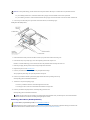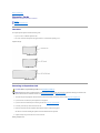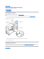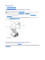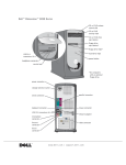
1
Dell Precision™ WorkStation 330 Systems Service Manual Before You Begin
Computer Cover
Interior Service Label
Inside Your Computer
System Board Components
Front Panel (Mini Tower Chassis Only)
Front-Panel Inserts
Front-Panel Buttons
Power Supply
System Memory
Disk Drives and Media
AGP Card Brace (Mini Tower Chassis Only)
Expansion Cards
Expansion-Card Guide
I/O Cooling Fan (Mini Tower Chassis Only)
Control Panel
Hard-Drive Thermal Sensor
Chassis Intrusion Switch
Speaker
Microprocessor Airflow Shroud
Microprocessor
Microprocessor Cooling Fan
VRM
System Battery
System Board
Information in this document is subject to change without notice.
© 2000 Dell Computer Corporation. All rights reserved.
Reproduction in any manner whatsoever without the written permission of Dell Computer Corporation is strictly forbidden.
Trademarks used in this text: Dell Precision and the DELL E COM logo are trademarks of Dell Computer Corporation.
Other trademarks and trade names may be used in this document to refer to either the entities claiming the marks and names or their products. Dell Computer Corporation disclaims any proprietary interest in trademarks and trade names other than its
own.
Initial release: 16 Nov 2000
Back to Contents Page
AGP Card Brace (Mini Tower Chassis Only)
Dell Precision™ WorkStation 330 Systems Service Manual Removing the AGP Card Brace
Replacing the AGP Card Brace
Removing the AGP Card Brace
To access some components on the system board in the mini tower chassis, you may need to remove the accelerated graphics port (AGP) card brace.
CAUTION: Before you perform this procedure, see "Precautionary Measures."
1. Turn off the computer and peripherals, disconnect them from their electrical outlets, wait at least 5 seconds, and then remove the computer cover.
2. Lay the computer down on its right side.
3. Remove the screw that secures the AGP card brace to the chassis (see the following figure).
Removing the AGP Card Brace (Mini Tower Chassis)
4. Rotate the brace up until it disengages from the card guide at the front of the chassis. Then lift the brace away from the chassis.
Replacing the AGP Card Brace
To replace the AGP card brace, perform the removal procedure in reverse.
Back to Contents Page
Back to Contents Page
System Battery
Dell Precision™ WorkStation 330 Systems Service Manual Removing the System Battery
Replacing the System Battery
Removing the System Battery
CAUTION: There is a danger of the new battery exploding if it is installed incorrectly. Replace the battery only with the same or equivalent type
recommended by the manufacturer. Discard used batteries according to the manufacturer's instructions.
CAUTION: Before you perform this procedure, see "Precautionary Measures."
NOTICE: Before disconnecting a peripheral from the system or removing a component from the system board, verify that the standby power indicator on the
system board has turned off. To locate this indicator, see "System Board Components" or "Interior Service Label."
1. Turn off the computer and peripherals, disconnect them from their electrical outlets, wait at least 5 seconds, and then remove the computer cover.
2. Remove the battery.
To locate the battery on the system board, see "System Board Components" or "Interior Service Label."
Pry the battery out of its socket with your fingers or with a blunt, nonconductive object, such as a plastic screwdriver.
Removing the System Battery
Replacing the System Battery
1. Install the new battery.
Orient the battery with the side labeled "+" facing up (see "Removing the System Battery"). Then insert the battery into the socket, and snap it into place.
2. Replace the computer cover and restart the system.
3. Enter system setup and enter the current time and date. Then exit system setup and save the information.
Back to Contents Page
Back to Contents Page
Before You Begin
Dell Precision™ WorkStation 330 Systems Service Manual Precautionary Measures
Recommended Tools
Restarting the System
Precautionary Measures
Before you remove the computer cover, perform the following steps in the sequence indicated.
1. Turn off your computer and any peripherals.
2. Disconnect your computer and peripherals from their power sources. Also, disconnect any telephone or telecommunication lines from the computer.
Doing so reduces the potential for personal injury or shock.
3. If you are disconnecting a peripheral from the computer or are removing a component from the system board, wait 10 to 20 seconds after disconnecting the
computer from AC power before disconnecting the peripheral or removing the component to avoid possible damage to the system board.
4. Wear a wrist grounding strap, and clip it to an unpainted metal surface, such as the padlock loop on the back of the chassis. If a wrist grounding strap is not
available, touch any unpainted metal surface on the back of the computer or on the computer chassis, such as the power supply, to discharge any static charge
from your body before touching anything inside the computer. While you work, periodically touch an unpainted metal surface on the computer chassis to
dissipate any static electricity that might harm internal components. Also avoid touching components or contacts on a card and avoid touching pins on a chip.
5. Verify that the standby power indicator on the system board is not on. If it is on, you may need to wait 10 to 30 seconds for it to go out. To locate this indicator,
see "System Board Components" or "Interior Service Label."
Recommended Tools
Some of the procedures in this document require the use of a #2 Phillips-head screwdriver.
Also, use a wrist grounding strap as explained in "Precautionary Measures."
Restarting the System
1. Replace the computer cover, reconnect the computer and peripherals to their electrical outlets, and turn them on.
NOTE: If enabled, the Chassis Intrusion option will cause the following message to be displayed at the next system start-up:
ALERT! Cover was previously removed.
2. To reset the Chassis Intrusion option, enter system setup, select the System Security option, and reset the Chassis Intrusion option to Enabled or
Enabled Silent.
NOTE: When the setup password is enabled, you must know the setup password before you can reset the Chassis Intrusion option.
Back to Contents Page
Back to Contents Page
Chassis Intrusion Switch
Dell Precision™ WorkStation 330 Systems Service Manual Desktop Chassis
Mini Tower Chassis
Desktop Chassis
l
Removing the chassis intrusion switch
l
Replacing the chassis intrusion switch
Removing the Chassis Intrusion Switch (Desktop Chassis)
CAUTION: Before you perform this procedure, see "Precautionary Measures."
NOTICE: Before disconnecting a peripheral from the system or removing a component from the system board, verify that the standby power indicator on the
system board has turned off. To locate this indicator, see "System Board Components" or "Interior Service Label."
1. Turn off the computer and peripherals, disconnect them from their electrical outlets, wait at least 5 seconds, and then remove the computer cover.
2. Remove the hard-drive bracket.
3. Remove all expansion cards.
4. Remove the expansion-card guide.
5. Disconnect the chassis intrusion switch cable from the control-panel connector (ALERT). To locate this connector, see "Control Panel Components."
6. Feed the chassis intrusion switch cable through the routing hole in the front wall of the chassis (see the following figure).
7. From inside the chassis, slide the chassis intrusion switch toward the left side wall of the chassis to release it from the chassis.
8. Lift the chassis intrusion switch and switch cable away from the chassis.
Removing the Chassis Intrusion Switch (Desktop Chassis)
Replacing the Chassis Intrusion Switch (Desktop Chassis)
NOTE: When mounting the chassis intrusion switch in the clip in the front wall of the chassis, ensure that the sensor cable is oriented toward the left side wall of
the chassis.
To replace the chassis intrusion switch, perform the removal procedure in reverse.
Mini Tower Chassis
l
Removing the chassis intrusion switch
l
Replacing the chassis intrusion switch
Removing the Chassis Intrusion Switch (Mini Tower Chassis)
CAUTION: Before you perform this procedure, see "Precautionary Measures."
NOTICE: Before disconnecting a peripheral from the system or removing a component from the system board, verify that the standby power indicator on the
system board has turned off. To locate this indicator, see "System Board Components" or "Interior Service Label."
1. Turn off the computer and peripherals, disconnect them from their electrical outlets, wait at least 5 seconds, and then remove the computer cover.
2. Remove the front panel.
3. Remove the AGP card brace.
4. Remove all expansion cards.
5. Remove the expansion-card guide.
6. Disconnect the chassis intrusion switch cable from the control-panel connector (ALERT). To locate this connector, see "Control Panel Components."
7. Feed the chassis intrusion switch cable through the routing holes in the drive door and the front wall of the chassis (see the following figure).
NOTE: You must open the drive door to feed the chassis intrusion switch cable through the cable routing holes. The switch cable routes through an
enlarged hole in the front chassis wall and through a hole in the drive door.
8. Slide the chassis intrusion switch up out of its slot on the left side of the chassis.
9. Lift the chassis intrusion switch and switch cable away from the chassis.
Removing the Chassis Intrusion Switch (Mini Tower Chassis)
Replacing the Chassis Intrusion Switch (Mini Tower Chassis)
To replace the chassis intrusion switch, perform the removal procedure in reverse.
Back to Contents Page
Back to Contents Page
Control Panel
Dell Precision™ WorkStation 330 Systems Service Manual Components
Desktop Chassis
Mini Tower Chassis
Components
The following figure shows the control panel and the location of its principal connectors and components.
Control Panel Components
Desktop Chassis
l
Removing the control panel
l
Replacing the control panel
Removing the Control Panel (Desktop Chassis)
CAUTION: Before you perform this procedure, see "Precautionary Measures."
NOTICE: Before disconnecting a peripheral from the system or removing a component from the system board, verify that the standby power indicator on the
system board has turned off. To locate this indicator, see "System Board Components" or "Interior Service Label."
1. Turn off the computer and peripherals, disconnect them from their electrical outlets, wait at least 5 seconds, and then remove the computer cover.
2. Remove the hard-drive bracket.
3. Remove all expansion cards.
4. Remove the expansion-card guide.
5. Disconnect the control-panel cable from the control-panel (PANEL) connector on the system board. To locate the control-panel connector, see "System Board
Components" or "Interior Service Label."
6. Feed the control-panel ribbon cable through the routing holes in the bottom and front wall of the chassis.
7. Disconnect the speaker and chassis intrusion switch cables from the control-panel connectors. To locate these connectors, see "Control Panel Components."
8. Remove the mounting screw.
9. Lift the control panel and control-panel ribbon cable away from the chassis.
Removing the Control Panel (Desktop Chassis)
Replacing the Control Panel (Desktop Chassis)
NOTE: When mounting the control panel on the chassis, ensure that the control-panel alignment hole is positioned over the guide pin. See "Removing the
Control Panel (Desktop Chassis)."
To replace the control panel, perform the removal procedure in reverse.
Mini Tower Chassis
l
Removing the control panel
l
Replacing the control panel
Removing the Control Panel (Mini Tower Chassis)
CAUTION: Before you perform this procedure, see "Precautionary Measures."
NOTICE: Before disconnecting a peripheral from the system or removing a component from the system board, verify that the standby power indicator on the
system board has turned off. To locate this indicator, see "System Board Components" or "Interior Service Label."
1. Turn off the computer and peripherals, disconnect them from their electrical outlets, wait at least 5 seconds, and then remove the computer cover.
2. Remove the front panel.
3. Remove the AGP card brace.
4. Remove all expansion cards.
5. Remove the expansion-card guide.
6. Disconnect the control-panel cable from the control-panel (PANEL) connector on the system board. To locate the control-panel connector, see "System Board
Components" or "Interior Service Label."
7. Feed the control-panel ribbon cable through the routing holes in the bottom and front wall of the chassis.
NOTE: You must open the drive door and free the control-panel cable from the clasp on the drive door.
8. Disconnect the speaker and chassis intrusion switch cables from the control-panel connectors. To locate these connectors, see "Control Panel Components."
9. Remove the mounting screw.
10. Lift the control panel and control-panel ribbon cable away from the chassis.
Removing the Control Panel (Mini Tower Chassis)
Replacing the Control Panel (Mini Tower Chassis)
NOTE: When mounting the control panel on the drive door, Ensure that the control-panel alignment hole is positioned over the guide pin. See "Removing the
Control Panel (Mini Tower Chassis)."
To replace the control panel, perform the removal procedure in reverse.
Back to Contents Page
Back to Contents Page
Computer Cover
Dell Precision™ WorkStation 330 Systems Service Manual Desktop Chassis
Mini Tower Chassis
Desktop Chassis
l
Removing the computer cover
l
Replacing the computer cover
Removing the Computer Cover (Desktop Chassis)
CAUTION: Before you perform this procedure, see "Precautionary Measures."
1. Turn off the computer and peripherals, and disconnect them from their electrical outlets.
2. If installed, remove the padlock from the padlock ring on the back panel.
3. Remove the computer cover.
a. Press the two cover release buttons located on the left and right sides of the cover (see the following figure).
b. Rotate the back of the cover upward, away from the chassis.
Removing the Cover (Desktop Chassis)
c. Lift the cover away from the chassis.
Replacing the Computer Cover (Desktop Chassis)
1. Check all cable connections and fold cables out of the way so that they do not catch on the computer cover. Ensure that cables are not routed over the drive
cage—they will prevent the cover from closing properly.
2. Ensure that no tools or extra parts (including screws) are left inside the computer chassis.
3. Replace the computer cover.
a. Hold the cover at a slight angle as shown in the following figure.
b. Fit the three cover hooks into the recessed slots at the bottom of chassis. (It might be helpful to look down into the chassis to verify that the hooks are in
place.)
c. Rotate the cover downward and into position. Ensure that the two cover release buttons click into place.
Replacing the Cover (Desktop Chassis)
Mini Tower Chassis
l
Removing the computer cover
l
Replacing the computer cover
Removing the Computer Cover (Mini Tower Chassis)
CAUTION: Before you perform this procedure, see "Precautionary Measures."
1. Turn off the computer and peripherals, and disconnect them from their electrical outlets.
2. If installed, remove the padlock from the padlock ring on the back panel.
3. Remove the computer cover.
a. Face the back of the computer and slide the outer padlock ring to the left to unlock the cover release mechanism (see the following figure).
Cover Release Mechanism (Mini Tower Chassis)
b. Press the cover release button located at the bottom-left corner of the front panel (see the following figure).
c. Rotate the bottom of the cover outward, away from the chassis.
Removing the Cover (Mini Tower Chassis)
d. Lift the cover away from the chassis.
e. Lay the computer down on its right side before you begin working inside the chassis.
Replacing the Computer Cover (Mini Tower Chassis)
1. Check all cable connections and fold cables out of the way so that they do not catch on the computer cover. Ensure that cables are not routed over the drive
cage—they will prevent the cover from closing properly.
2. Ensure that no tools or extra parts (including screws) are left inside the computer chassis.
3. Replace the computer cover.
a. Hold the cover at a slight angle as shown in the following figure. While aligning the top of the cover with the top of the chassis, insert the three hooks on
the cover into the three recessed slots on the computer chassis.
b. Rotate the cover downward toward the bottom of the chassis. With both hands, press against the bottom edge of the cover to ensure that the securing
hooks at the bottom of the cover click into place.
Replacing the Cover (Mini Tower Chassis)
c. Slide the two parts of the padlock ring together to lock the cover release mechanism.
Back to Contents Page
Back to Contents Page
Disk Drives and Media
Dell Precision™ WorkStation 330 Systems Service Manual Desktop Chassis
Mini Tower Chassis
Desktop Chassis
l
Drive locations
l
Removing the diskette drive
l
Replacing the diskette drive
l
Removing a CD, Zip, or other externally accessible drive
l
Replacing a CD, Zip, or other externally accessible drive
l
Removing a hard drive
l
Replacing a hard drive
Drive Locations (Desktop Chassis)
Removing the Diskette Drive (Desktop Chassis)
CAUTION: Before you perform this procedure, see "Precautionary Measures."
NOTICE: Before disconnecting a peripheral from the system or removing a component from the system board, verify that the standby power indicator on the
system board has turned off. To locate this indicator, see "System Board Components" or "Interior Service Label."
1. Turn off the computer and peripherals, disconnect them from their electrical outlets, wait at least 5 seconds, and then remove the computer cover.
2. Rotate the power supply away from the system board.
3. Disconnect the DC power and interface cables from the back of the drive.
4. Press the green diskette-drive bracket release button and slide the drive assembly out of the chassis (see the following figure).
Removing the Diskette-Drive Bracket (Desktop Chassis)
5. Remove the mounting screw.
6. Rotate the left side of the diskette drive upward and lift it free from the drive bracket (see the following figure).
Removing the Diskette Drive from the Bracket (Desktop Chassis)
Replacing the Diskette Drive (Desktop Chassis)
1. Mount the diskette drive on the bracket:
a. Lower the right side of the diskette drive onto the bracket, inserting the drive retention pins into the screw holes on the drive. See "Removing the Diskette
Drive from the Bracket (Desktop Chassis)."
b. Lower the left side of the diskette drive downward and secure it to the bracket with the screw you removed in step 5 of "Removing the Diskette Drive
(Desktop Chassis)."
2. Slide the drive assembly into the chassis until the green diskette-drive bracket release button snaps securely into place. See "Removing the Diskette-Drive
Bracket (Desktop Chassis)."
3. Connect the interface cable for the drive. To locate this connector, see "System Board Components" or "Interior Service Label."
NOTICE: To avoid possible damage, you must match the colored strip on the interface cable with pin 1 on both the drive and system board connectors.
4. Connect a DC power cable to the power input connector on the back of the drive.
5. Ensure that all cables are firmly connected. Fold cables out of the way to provide airflow for the fan and cooling vents.
6. Rotate the power supply back into position until the securing tab snaps into the release latch.
7. Replace the computer cover and restart the system.
8. Run the Dell Diagnostics to verify that the drive is operating properly.
Removing a CD, Zip, or Other Externally Accessible Drive (Desktop Chassis)
CAUTION: Before you perform this procedure, see "Precautionary Measures."
NOTICE: Before disconnecting a peripheral from the system or removing a component from the system board, verify that the standby power indicator on the
system board has turned off. To locate this indicator, see "System Board Components" or "Interior Service Label."
1. Turn off the computer and peripherals, disconnect them from their electrical outlets, wait at least 5 seconds, and then remove the computer cover.
2. Rotate the power supply away from the system board.
3. Disconnect the DC power and interface cables from the back of the drive.
4. Remove the drive bracket from the chassis drive bay you want to use.
Squeeze together the metal tabs that extend from each side of the drive bracket, and pull the bracket out of the bay (see the following figure).
Removing a Drive Bracket (Desktop Chassis)
5. Remove the drive from the bracket.
Turn the drive/bracket assembly upside down and remove the four screws that secure the drive to the bracket (see the following figure).
Removing the Drive from the Bracket
Replacing a CD, Zip, or Other Externally Accessible Drive (Desktop Chassis)
1. Attach the new drive to the drive bracket.
Turn the drive upside down, and fit the bracket on the drive so that the screw holes align. To ensure proper installation, all screw holes should be aligned and the
tabs on the front of the bracket should be flush with the front of the drive (see "Removing the Drive from the Bracket").
To further ensure proper positioning of the drive in the chassis, insert and tighten all four screws in the order in which the holes are numbered (the holes are
marked "1" through "4").
2. Slide the new drive/bracket assembly into the drive bay until both drive bracket tabs snap securely into place (see the following figure).
Installing the Drive Bracket (Desktop Chassis)
3. Connect the interface cable for the drive. See "Attaching Drive Cables (Desktop Chassis)."
NOTICE: To avoid possible damage, you must match the colored strip on the interface cable with pin 1 on both the drive and system board connectors.
a. If you are installing an EIDE device, ensure that the interface cable is properly connected to the EIDE connector on the system board.
b. If you are installing a SCSI device, ensure that the SCSI interface cable is properly connected to the interface connector on the SCSI controller board.
4. Connect a DC power cable to the power input connector on the back of the drive (see the following figure).
Attaching Drive Cables (Desktop Chassis)
5. Ensure that all cables are firmly connected. Fold cables out of the way to provide airflow for the fan and cooling vents.
6. If the chassis drive bay was previously empty, remove the corresponding insert from the computer cover.
Hold the cover with the outside facing you. Press the ends of the insert with your thumbs until the insert snaps free of the cover.
7. Rotate the power supply back into position until the securing tab snaps into the release latch.
8. Replace the computer cover and restart the system.
9. If the drive you installed is a hard drive, enter system setup, and update the drive settings.
After you update the system settings, exit system setup and reboot the computer.
10. If the device you installed is a hard drive, partition and logically format the drive before proceeding to the next step.
See the operating system's documentation for instructions.
11. Test the drive to verify that it is operating properly.
l
If the drive you installed is a hard drive, run the Dell Diagnostics to test the drive.
l
For other types of drives, see the drive's documentation for information on testing the drive.
12. If the drive you installed is the primary hard drive, install the operating system on the drive.
See the operating system's documentation for instructions.
NOTE: Tape drives sold by Dell come with their own operating software and documentation. After you install a tape drive, refer to the documentation
that came with the drive for instructions on installing and using the tape drive software.
Removing a Hard Drive (Desktop Chassis)
CAUTION: Before you perform this procedure, see "Precautionary Measures."
NOTICE: Before disconnecting a peripheral from the system or removing a component from the system board, verify that the standby power indicator on the
system board has turned off. To locate this indicator, see "System Board Components" or "Interior Service Label."
1. Turn off the computer and peripherals, disconnect them from their electrical outlets, wait at least 5 seconds, and then remove the computer cover.
2. Rotate the power supply away from the system board.
3. Disconnect the DC power and interface cables from the back of the drive.
4. Remove the drive bracket from the chassis.
Remove the screw holding the drive bracket in the chassis. Lift the drive bracket up to disengage it from the latch on the externally accessible drive bay and the
three hooks on the front of the chassis (see the following figure).
Removing the Hard-Drive Bracket (Desktop Chassis)
5. Remove the four screws that secure the drive in the bracket (see the following figure).
6. Remove the old drive from the bracket
Removing a Hard Drive from the Bracket (Desktop Chassis)
Replacing a Hard Drive (Desktop Chassis)
1. Slide the drive into one of bracket bays, oriented so that the connectors on the back of the drive will face the interior of the chassis when the bracket is
reinstalled.
NOTE: Orient the drive in the bracket so that its bottom will face the left side of the chassis when the bracket is installed in the chassis.
2. Align the screw holes of the drive and bracket, and secure the drive in the bracket using the screws that came with the upgrade kit. See "Removing a Hard Drive
from the Bracket (Desktop Chassis)."
3. Reinstall the hard-drive bracket in the chassis (see the following figure).
Insert the bracket into the chassis by inserting the hooks in the slots on the front of the chassis. Then lower the bracket to the bottom of the chassis, making sure
that the latch on the externally accessible drive bay is engaged. Replace the screw holding the drive bracket to the drive bay.
Installing the Hard-Drive Bracket (Desktop Chassis)
4. Connect the interface cable for the drive. See "Attaching Hard-Drive Cables (Desktop Chassis)."
NOTICE: To avoid possible damage, you must match the colored strip on the interface cable with pin 1 on both the drive and system board connectors.
a. If you are installing an EIDE device, ensure that the IDE interface cable is properly connected to the EIDE connector on the system board.
b. If you are installing a SCSI device, ensure that the SCSI interface cable is properly connected to the interface connector on the SCSI controller board.
5. Connect a DC power cable to the power input connector on the back of the drive (see the following figure).
Attaching Hard-Drive Cables (Desktop Chassis)
6. Ensure that all cables are firmly connected. Fold cables out of the way to provide airflow for the fan and cooling vents.
7. Ensure that the control panel cable is firmly connected to the system board.
The control panel contains the hard-drive activity indicator. To locate the control panel system board connector, see "System Board Components" or "Interior
Service Label."
8. Rotate the power supply back into position until the securing tab snaps into the release latch.
9. Replace the computer cover and restart the system.
10. Enter system setup, and update the drive settings.
After you update the system settings, exit system setup and reboot the computer.
11. Partition and logically format the drive before proceeding to the next step.
See the operating system's documentation for instructions.
12. Run the Dell Diagnostics to test the drive.
13. If the hard drive you installed is the primary drive, install the operating system on the drive.
See the operating system's documentation for instructions.
Mini Tower Chassis
l
Drive locations
l
Removing the diskette drive
l
Replacing the diskette drive
l
Removing a CD, Zip, or other externally accessible drive
l
Replacing a CD, Zip, or other externally accessible drive
l
Removing a hard drive
l
Replacing a hard drive
Drive Locations (Mini Tower Chassis)
Removing the Diskette Drive (Mini Tower Chassis)
CAUTION: Before you perform this procedure, see "Precautionary Measures."
NOTICE: Before disconnecting a peripheral from the system or removing a component from the system board, verify that the standby power indicator on the
system board has turned off. To locate this indicator, see "System Board Components" or "Interior Service Label."
1. Turn off the computer and peripherals, disconnect them from their electrical outlets, wait at least 5 seconds, and then remove the computer cover.
2. Rotate the power supply away from the system board.
3. Remove the front panel.
4. Disconnect the DC power and interface cables from the back of the drive.
5. Press the green diskette-drive bracket release button and slide the drive assembly out of the chassis (see the following figure).
Removing the Diskette-Drive Bracket (Mini Tower Chassis)
6. Remove the mounting screw.
7. Rotate the left side of the diskette drive upward and lift it free from the drive bracket (see the following figure).
Removing the Diskette Drive from the Bracket (Mini Tower Chassis)
Replacing the Diskette Drive (Mini Tower Chassis)
1. Mount the diskette drive on the bracket:
a. Lower the right side of the diskette drive onto the bracket, inserting the drive retention pins into the screw holes on the drive. See "Removing the Diskette
Drive from the Bracket (Mini Tower Chassis)."
b. Lower the left side of the diskette drive downward and secure it to the bracket with the screw you removed in step 6 of "Removing the Diskette Drive
(Mini Tower Chassis)."
2. Slide the drive assembly into the chassis until the green diskette-drive bracket release button snaps securely into place. See "Removing the Diskette-Drive
Bracket (Mini Tower Chassis)."
3. Connect the interface cable for the drive. To locate this connector, see "System Board Components" or "Interior Service Label."
NOTICE: To avoid possible damage, you must match the colored strip on the interface cable with pin 1 on both the drive and system board connectors.
4. Connect a DC power cable to the power input connector on the back of the drive.
5. Ensure that all cables are firmly connected. Fold cables out of the way to provide airflow for the fan and cooling vents.
6. Rotate the power supply back into position until the securing tab snaps into the release latch.
7. Replace the computer cover and restart the system.
8. Run the Dell Diagnostics to verify that the drive is operating properly.
Removing a CD, Zip, or Other Externally Accessible Drive (Mini Tower Chassis)
CAUTION: Before you perform this procedure, see "Precautionary Measures."
NOTICE: Before disconnecting a peripheral from the system or removing a component from the system board, verify that the standby power indicator on the
system board has turned off. To locate this indicator, see "System Board Components" or "Interior Service Label."
1. Turn off the computer and peripherals, disconnect them from their electrical outlets, wait at least 5 seconds, and then remove the computer cover.
2. Rotate the power supply away from the system board.
3. Remove the front panel.
4. Disconnect the DC power and interface cables from the back of the drive.
5. Remove the drive bracket from the chassis drive bay you want to use.
Squeeze together the metal tabs that extend from each side of the drive bracket, and pull the bracket out of the bay (see the following figure).
Removing a Drive Bracket (Mini Tower Chassis)
6. Remove the drive from the bracket.
Turn the drive/bracket assembly upside down and remove the four screws that secure the drive to the bracket (see the following figure).
Removing the Drive from the Bracket
Replacing a CD, Zip, or Other Externally Accessible Drive (Mini Tower Chassis)
1. Attach the new drive to the drive bracket.
Turn the drive upside down, and fit the bracket on the drive so that the screw holes align. To ensure proper installation, all screw holes should be aligned and the
tabs on the front of the bracket should be flush with the front of the drive (see "Removing the Drive from the Bracket").
To further ensure proper positioning of the drive in the chassis, insert and tighten all four screws in the order in which the holes are numbered (the holes are
marked "1" through "4").
2. Slide the new drive/bracket assembly into the drive bay until both drive bracket tabs snap securely into place (see the following figure).
Installing the Drive Bracket (Mini Tower Chassis)
3. Connect the interface cable for the drive. See "Attaching Drive Cables (Mini Tower Chassis)."
NOTICE: To avoid possible damage, you must match the colored strip on the interface cable with pin 1 on both the drive and system board connectors.
a. If you are installing an EIDE device, ensure that the interface cable is properly connected to the EIDE connector on the system board.
b. If you are installing a SCSI device, ensure that the SCSI interface cable is properly connected to the interface connector on the SCSI controller board.
4. Connect a DC power cable to the power input connector on the back of the drive (see the following figure).
Attaching Drive Cables (Mini Tower Chassis)
5. Ensure that all cables are firmly connected. Fold cables out of the way to provide airflow for the fan and cooling vents.
6. If the chassis drive bay was previously empty, remove the corresponding insert from the front panel.
Hold the front panel with the outside facing you. Press the ends of the insert with your thumbs until the insert snaps free of the front panel.
7. Replace the front panel.
8. Rotate the power supply back into position until the securing tab snaps into the release latch.
9. Replace the computer cover and restart the system.
10. If the drive you installed is a hard drive, enter system setup, and update the drive settings.
After you update the system settings, exit system setup and reboot the computer.
11. If the device you installed is a hard drive, partition and logically format the drive before proceeding to the next step.
See the operating system's documentation for instructions.
12. Test the drive to verify that it is operating properly.
l
If the drive you installed is a hard drive, run the Dell Diagnostics to test the drive.
l
For other types of drives, see the drive's documentation for information on testing the drive.
13. If the drive you installed is the primary hard drive, install the operating system on the drive.
See the operating system's documentation for instructions.
NOTE: Tape drives sold by Dell come with their own operating software and documentation. After you install a tape drive, refer to the documentation that came
with the drive for instructions on installing and using the tape drive software.
Removing a Hard Drive (Mini Tower Chassis)
CAUTION: Before you perform this procedure, see "Precautionary Measures."
NOTICE: Before disconnecting a peripheral from the system or removing a component from the system board, verify that the standby power indicator on the
system board has turned off. To locate this indicator, see "System Board Components" or "Interior Service Label."
1. Turn off the computer and peripherals, disconnect them from their electrical outlets, wait at least 5 seconds, and then remove the computer cover.
2. Rotate the power supply away from the system board.
3. Remove the front panel.
4. Disconnect the DC power and interface cables from the back of the drive.
5. Remove the drive bracket from the chassis.
Pull the drive door forward and down until the hard-drive bracket is ejected halfway out of the chassis (see the following figure). Then grasp the bracket and pull
it completely out of the chassis.
Removing the Hard-Drive Bracket (Mini Tower Chassis)
6. Remove the four screws that secure the drive in the bracket (see the following figure).
7. Remove the drive from the bracket
Removing a Hard Drive from the Bracket (Mini Tower Chassis)
Replacing a Hard Drive (Mini Tower Chassis)
1. Slide the drive into one of bracket bays, oriented so that the connectors on the back of the drive will face the interior of the chassis when the bracket is
reinstalled. See "Removing a Hard Drive from the Bracket (Mini Tower Chassis)."
NOTE: Orient the drive in the bracket so that its bottom will face the left side of the chassis when the bracket is installed in the chassis.
2. Align the screw holes of the drive and bracket, and secure the drive in the bracket using the screws that came with the upgrade kit.
3. Reinstall the hard-drive bracket in the chassis (see the following figure).
Insert the drive bracket into the chassis, sliding it in until the tabs snap into place. Rotate the drive door upward to the chassis until it snaps securely into place.
NOTE: When you rotate the drive door back into place, ensure that the tabs on the drive door are inserted between the drive bracket and the drive cage.
NOTE: Be sure to fold down the drive door handle so that the front panel can be replaced on the chassis.
Installing the Hard-Drive Bracket (Mini Tower Chassis)
4. Connect the interface cable for the drive. See "Attaching Hard-Drive Cables (Mini Tower Chassis)."
NOTICE: To avoid possible damage, you must match the colored strip on the interface cable with pin 1 on both the drive and system board connectors.
a. If you are installing an EIDE device, ensure that the IDE interface cable is properly connected to the EIDE connector on the system board.
b. If you are installing a SCSI device, ensure that the SCSI interface cable is properly connected to the interface connector on the SCSI controller board.
5. Connect a DC power cable to the power input connector on the back of the drive (see the following figure).
Attaching Hard-Drive Cables (Mini Tower Chassis)
6. Ensure that all cables are firmly connected. Fold cables out of the way to provide airflow for the fan and cooling vents.
7. Ensure that the control panel cable is firmly connected to the system board.
The control panel contains the hard-drive activity indicator. To locate the control panel system board connector, see "System Board Components" or "Interior
Service Label."
8. Replace the front panel.
9. Rotate the power supply back into position until the securing tab snaps into the release latch.
10. Replace the computer cover and restart the system.
11. Enter system setup, and update the drive settings.
After you update the system settings, exit system setup and reboot the computer.
12. Partition and logically format the drive before proceeding to the next step.
See the operating system's documentation for instructions.
13. Run the Dell Diagnostics to test the drive.
14. If the hard drive you installed is the primary drive, install the operating system on the drive.
See the operating system's documentation for instructions.
Back to Contents Page
Back to Contents Page
Expansion Cards
Dell Precision™ WorkStation 330 Systems Service Manual Overview
Removing an Expansion Card
Overview
The computer provides expansion slots for the following cards:
l
Up to five 32-bit, 33-MHz PCI expansion cards.
l
One 32-bit AGP card. The expansion slot supports AGP 4x or 2x Pro50 modes operating at 1.5 V.
Expansion Card Types
Removing an Expansion Card
CAUTION: Before you perform this procedure, see "Precautionary Measures."
NOTICE: Before disconnecting a peripheral from the system or removing a component from the system board, verify that the standby power indicator on the
system board has turned off. To locate this indicator, see "System Board Components" or "Interior Service Label."
1. Turn off the computer and peripherals, disconnect them from their electrical outlets, wait at least 5 seconds, and then remove the computer cover.
2. If you have a mini tower chassis, lay the computer down on its right side.
3. If you have a mini tower chassis and you are removing an AGP card, remove the AGP card brace.
4. If necessary, disconnect any cables connected to the card.
5. Remove the screw that secures the expansion card bracket to the chassis (see the following figure).
Save the screw to use when installing the expansion card or filler bracket later in this procedure.
6. Grasp the card by its top corners, and ease it out of its connector.
Removing an Expansion Card
NOTICE: An AGP Pro50 card may use multiple screws on its bracket. Install all screws on the expansion card's bracket.
7. If you are removing the card permanently, install a filler bracket in the empty card-slot opening, using the screw you removed in step 5.
If you need a filler bracket, contact Dell and order part number 81808. See the User's Guide for information on contacting Dell.
NOTE: Installing filler brackets over empty card-slot openings is necessary to maintain Federal Communications Commission (FCC) certification of the
system. The brackets also keep dust and dirt out of your computer.
8. If you removed the AGP brace, replace it.
9. If you have a mini tower chassis, stand the computer upright.
10. Replace the computer cover and restart the system.
11. If you removed a sound card, perform the following steps:
a. Enter system setup, select Integrated Devices and change the setting for Sound to On.
b. Connect external audio devices to the audio connectors on the system back panel.
12. If you removed an add-in NIC, perform the following steps:
a. Enter system setup, select Integrated Devices and change the setting for Network Interface Card to On.
b. Connect the network cable to the integrated NIC connector on the system back panel.
Back to Contents Page
Back to Contents Page
Expansion-Card Guide
Dell Precision™ WorkStation 330 Systems Service Manual Desktop Chassis
Mini Tower Chassis
Desktop Chassis
l
Removing the expansion-card guide
l
Replacing the expansion-card guide
Removing the Expansion-Card Guide (Desktop Chassis)
CAUTION: Before you perform this procedure, see "Precautionary Measures."
NOTICE: Before disconnecting a peripheral from the system or removing a component from the system board, verify that the standby power indicator on the
system board has turned off. To locate this indicator, see "System Board Components" or "Interior Service Label."
1. Turn off the computer and peripherals, disconnect them from their electrical outlets, wait at least 5 seconds, and then remove the computer cover.
2. Remove the hard-drive bracket.
3. Remove all expansion cards.
4. Remove the expansion-card guide:
a. Face the computer from the front.
b. From the outside of the chassis, press in the two tabs on the left side of the card guide.
This will release the left card-guide tabs from the chassis.
c. Rotate the released side of the card guide away from the front chassis wall.
d. With the released side of the card guide away from the chassis wall, pull the card guide back away from the chassis (see the following figure).
Removing the Expansion-Card Guide (Desktop Chassis)
Replacing the Expansion-Card Guide (Desktop Chassis)
Insert the two right tabs in the slots in the front chassis wall. Then, rotate the card guide toward the front chassis wall until the two left tabs snap into the slots in the left
side chassis wall. See "Removing the Expansion-Card Guide (Desktop Chassis)."
Mini Tower Chassis
l
Removing the expansion-card guide
l
Replacing the expansion-card guide
Removing the Expansion-Card Guide (Mini Tower Chassis)
CAUTION: Before you perform this procedure, see "Precautionary Measures."
NOTICE: Before disconnecting a peripheral from the system or removing a component from the system board, verify that the standby power indicator on the
system board has turned off. To locate this indicator, see "System Board Components" or "Interior Service Label."
1. Turn off the computer and peripherals, disconnect them from their electrical outlets, wait at least 5 seconds, and then remove the computer cover.
2. Lay the computer down on its right side.
3. Remove the AGP card brace.
4. Remove all expansion cards.
5. Disconnect the fan power cable from its connector on the system board (FAN2). To locate this connector, see "System Board Components" or "Interior Service
Label."
6. Remove the expansion-card guide:
NOTE: The I/O cooling fan is mounted on the expansion-card guide.
a. From the outside of the chassis, press in the tab on the top of the card guide.
This will release the card-guide tab from the chassis.
b. Rotate the released side of the card guide away from the front chassis wall.
c. With the released side of the card guide away from the chassis wall, pull the card guide up away from the chassis (see the following figure).
Removing the Expansion-Card Guide (Mini Tower Chassis)
Replacing the Expansion-Card Guide (Mini Tower Chassis)
Insert the two bottom tabs in the slots in the chassis wall. Then, rotate the card guide toward the front chassis wall until the top tab snaps into the slot in the front chassis
wall. See "Removing the Expansion-Card Guide (Mini Tower Chassis)."
Back to Contents Page
Back to Contents Page
Front Panel (Mini Tower Chassis Only)
Dell Precision™ WorkStation 330 Systems Service Manual Removing the Front Panel
Replacing the Front Panel
Removing the Front Panel
CAUTION: Before you perform this procedure, see "Precautionary Measures."
1. Turn off the computer and peripherals, disconnect them from their electrical outlets, wait at least 5 seconds, and then remove the computer cover.
2. Release the front panel by pressing the green front-panel release button marked with the icon (see the following figure).
Removing the Front Panel (Mini Tower Chassis)
3. While pressing the front-panel release button, rotate the top of the panel outward, away from the chassis.
4. Lift the panel away from the chassis.
Replacing the Front Panel
Fit the two front-panel retaining hooks into the recessed slots at the bottom of the chassis. See "Removing the Front Panel (Mini Tower Chassis)." Then rotate the top
of the panel toward the chassis until the front-panel latches snap into the tabs on the front panel.
Back to Contents Page
Back to Contents Page
Front-Panel Buttons
Dell Precision™ WorkStation 330 Systems Service Manual Desktop Chassis
Mini Tower Chassis
Desktop Chassis
l
Removing front-panel buttons
l
Replacing front-panel buttons
Removing Front-Panel Buttons (Desktop Chassis)
CAUTION: Before you perform this procedure, see "Precautionary Measures."
1. Turn off the computer and peripherals, disconnect them from their electrical outlets, wait at least 5 seconds, and then remove the computer cover.
2. Lay the computer cover upside down, with the back of the cover facing you.
3. Remove the front-panel buttons:
l
To remove the 3.5-inch diskette-drive eject button, pull gently on the button until its clip disengages the front panel of the computer cover. Lift the
button up to free it from the cover.
l
To remove the power button, use a small screwdriver to push in the two plastic clips that secure the button to the computer cover.
When the clips disengage, the button comes free from the front panel of the computer cover.
l
To remove the reset button, use a small screwdriver to push in the three plastic clips that secure the button to the computer cover.
When the clips disengage, the button comes free from the front panel of the computer cover.
Removing Front-Panel Buttons (Desktop Chassis)
Replacing Front-Panel Buttons (Desktop Chassis)
Replace the front-panel buttons.
l
To replace the 3.5-inch diskette-drive eject button, rotate the button into the hole in the front panel of the computer cover and push gently on the button until
its clip secures it to the cover.
l
To replace the power button, insert the button into the hole in the front panel of the computer cover so that the button's clips secure it to the cover.
l
To replace the reset button, insert the button into the hole in the front panel of the computer cover so that the button's clips secure it to the cover.
Mini Tower Chassis
l
Removing front-panel buttons
l
Replacing front-panel buttons
Removing Front-Panel Buttons (Mini Tower Chassis)
1. Turn off the computer and peripherals, disconnect them from their electrical outlets, wait at least 5 seconds, and then remove the computer cover.
2. Remove the front panel.
3. Lay the front panel down, with the inside of the panel facing up.
4. Remove the front-panel buttons:
l
To remove the power button, use a small screwdriver to push in the two plastic clips that secure the button to the computer cover.
When these clips are released, the button comes free from the front panel.
l
To remove the reset button, use a small screwdriver to push in the three plastic clips that secure the button to the computer cover.
When these clips are released, the button comes free from the front panel.
Removing Front-Panel Buttons (Mini Tower Chassis)
Replacing Front-Panel Buttons (Mini Tower Chassis)
Replace the front-panel buttons.
l
To replace the power button, insert the button into the hole in the front panel of the computer cover so that the button's clips secure it to the cover.
l
To replace the reset button, insert the button into the hole in the front panel of the computer cover so that the button's clips secure it to the cover.
Back to Contents Page
Back to Contents Page
Front-Panel Inserts
Dell Precision™ WorkStation 330 Systems Service Manual Desktop Chassis
Mini Tower Chassis
Desktop Chassis
l
Removing front-panel inserts
l
Replacing front-panel inserts
Removing Front-Panel Inserts (Desktop Chassis)
CAUTION: Before you perform this procedure, see "Precautionary Measures."
1. Turn off the computer and peripherals, disconnect them from their electrical outlets, wait at least 5 seconds, and then remove the computer cover.
2. Lay the computer cover upside down, with the front panel facing you.
3. Remove the front-panel insert for the chassis drive bay you want to use.
Use your thumbs to press the sides of the insert until it snaps free of the front panel (see the following figure).
Removing Front-Panel Inserts (Desktop Chassis)
Replacing Front-Panel Inserts (Desktop Chassis)
Position the two ring-tabs over the posts on the inside of the bay opening, and then press the ring tabs over the posts. See "Removing Front-Panel Inserts (Desktop
Chassis)."
Mini Tower Chassis
l
Removing front-panel inserts
l
Replacing front-panel inserts
Removing Front-Panel Inserts (Mini Tower Chassis)
CAUTION: Before you perform this procedure, see "Precautionary Measures."
1. Turn off the computer and peripherals, disconnect them from their electrical outlets, wait at least 5 seconds, and then remove the computer cover.
2. Remove the front panel.
3. Hold the front panel with the front facing you.
4. Remove the front-panel insert for the chassis drive bay you want to use.
Use your thumbs to press the sides of the insert until it snaps free of the front panel (see the following figure).
Removing Front-Panel Inserts (Mini Tower Chassis)
Replacing Front-Panel Inserts (Mini Tower Chassis)
Position the two ring-tabs over the posts on the inside of the bay opening, and then press the ring tabs over the posts. See "Removing Front-Panel Inserts (Mini Tower
Chassis)."
Back to Contents Page
Back to Contents Page
I/O Cooling Fan (Mini Tower Chassis Only)
Dell Precision™ WorkStation 330 Systems Service Manual Removing the I/O Cooling Fan
Replacing the I/O Cooling Fan
Removing the I/O Cooling Fan
CAUTION: Before you perform this procedure, see "Precautionary Measures."
NOTICE: Before disconnecting a peripheral from the system or removing a component from the system board, verify that the standby power indicator on the
system board has turned off. To locate this indicator, see "System Board Components" or "Interior Service Label."
1. Disconnect the fan power cable from its connector on the system board (FAN2). To locate this connector, see "System Board Components" or "Interior Service
Label."
2. Remove the expansion-card guide.
NOTE: The I/O cooling fan is mounted on the expansion-card guide.
3. Press the fan release tabs outward on the expansion-card guide and slide the fan out of the card guide (see the following figure).
Removing the I/O Cooling Fan (Mini Tower Chassis)
Replacing the I/O Cooling Fan
NOTICE: Ensure that the fan is properly installed on the guide bracket. When the fan is properly installed, the fan's manufacturer label should face the
expansion-card guide, and the fan's power cable should extend toward the system board. Airflow for the fan should enter the chassis through the front panel and
be moved by the fan to the chassis interior.
Insert the bottom of the cooling fan into the clips on the card guide. Then, press the top of the fan toward the card guide until the tabs on the card guide grasp the fan.
See "Removing the I/O Cooling Fan (Mini Tower Chassis)."
Back to Contents Page
Back to Contents Page
Inside Your Computer
Dell Precision™ WorkStation 330 Systems Service Manual Chassis Interior
Chassis Interior
The following figures show the desktop and mini tower chassis with their covers removed.
Desktop Chassis Interior
Mini Tower Chassis Interior
NOTE: Before you remove the cover from the mini tower chassis, you must first slide the outer padlock ring to the left to unlock the cover release mechanism.
See "Cover Release Mechanism (Mini Tower Chassis)."
Back to Contents Page
Back to Contents Page
System Memory
Dell Precision™ WorkStation 330 Systems Service Manual Removing a Memory Module
Replacing a Memory Module
Removing a Memory Module
CAUTION: Before you perform this procedure, see "Precautionary Measures."
CAUTION: RIMMs can get very hot during system operation. Be sure that the RIMMs have had sufficient time to cool before you touch them.
NOTICE: Before disconnecting a peripheral from the system or removing a component from the system board, verify that the standby power indicator on the
system board has turned off. To locate this indicator, see "System Board Components" or "Interior Service Label."
1. Turn off the computer and peripherals, disconnect them from their electrical outlets, wait at least 5 seconds, and then remove the computer cover.
2. If you have a mini tower chassis, lay the computer down on its right side.
3. Rotate the power supply away from the system board.
4. Remove the memory modules (RIMMs or CRIMMs):
a. Press the securing clips at each end of the socket outward simultaneously until the module pops out slightly from the socket (see the following figure).
b. Lift the module away from the socket.
NOTE: If you remove a module (RIMM or CRIMM), you must install another module in the empty socket before turning on the computer.
Removing a Memory Module
Replacing a Memory Module
1. Install the memory module:
a. Press the securing clips at each end of the socket outward until they snap open (see the following figure).
b. Align the slots on the bottom of the memory module with the two ridges inside the socket.
c. Press the memory module straight down into the socket until the securing clips snap into place at the ends of the module.
Installing a Memory Module
2. Rotate the power supply back into position until the securing tab snaps into the release latch.
3. If you have a mini tower chassis, stand the computer upright.
4. Replace the computer cover and restart the system.
The system detects that the new memory does not match the existing system configuration information and generates the following message:
The amount of system memory has changed.
Strike the F1 key to continue, F2 to run the setup utility
5. Enter system setup, and check the value for System Memory. The system should have already changed the value of System Memory to reflect the newly
installed memory. If the new total is correct, skip to step 7.
6. If the memory total is incorrect, repeat step 1 and step 3 of "Removing a Memory Module." Check the installed modules to ensure that they are seated properly
in their sockets. Then repeat step 2 through step 5 of this procedure.
7. When the System Memory total is correct, exit system setup.
8. Run the Dell Diagnostics to verify that the memory modules are operating properly.
Back to Contents Page
Back to Contents Page
Microprocessor
Dell Precision™ WorkStation 330 Systems Service Manual Removing the Microprocessor
Replacing the Microprocessor
Removing the Microprocessor
CAUTION: Before you perform this procedure, see "Precautionary Measures."
NOTICE: Before disconnecting a peripheral from the system or removing a component from the system board, verify that the standby power indicator on the
system board has turned off. To locate this indicator, see "System Board Components" or "Interior Service Label."
1. Remove the airflow shroud.
2. Remove the microprocessor heat sink:
a. For each of the metal clips that secure the heat sink to the microprocessor, press down on the clip's latch to release it from the heat-sink retention base.
Then lift the clip away from the heat sink (see the following figure).
b. Lift the heat sink away from the microprocessor.
NOTE: If you are you are installing a microprocessor upgrade kit from Dell, discard the original microprocessor heat sink and securing clips. Your
microprocessor upgrade kit should include a replacement microprocessor heat sink and two replacement securing clips. If you are not installing a
microprocessor upgrade kit from Dell, reuse the original heat sink and securing clips when replacing the microprocessor.
NOTICE: The bottom of the heat sink is coated with thermal grease that conducts heat from the microprocessor to the heat sink. Some of this grease will
remain on the microprocessor when you remove the heat sink. You can remove and replace the heat sink up to approximately 20 times before the thermal
grease is depleted to the point that performance is affected.
NOTICE: While you are replacing the the microprocessor, lay the heat sink down with the thermal grease facing upward. Do not lay the heat sink down with
the thermal grease touching the work surface.
Removing the Microprocessor Heat Sink
3. Remove the microprocessor from its connector.
Your microprocessor uses a zero insertion force (ZIF) socket with a lever-type handle that secures or releases the microprocessor.
To remove the microprocessor, pull the socket lever straight up until the microprocessor is released. Then remove the microprocessor from the socket (see the
following figure).
Removing the Microprocessor
Replacing the Microprocessor
1. Install the new microprocessor in the socket:
a. Ensure that the lever on the microprocessor socket is fully extended to the release position.
NOTICE: When you place the microprocessor in the socket, ensure that the microprocessor aligns properly with the socket. You must position the
microprocessor correctly in the socket to avoid damage.
b. Align pin 1 of the new microprocessor with pin 1 of the socket.
NOTE: Pin 1 of the microprocessor is indicated by a small dot or a triangle in one corner of the microprocessor. Pin 1 of the socket is indicated by a
small triangle in one corner of the socket. See "Replacing the Microprocessor."
c. Carefully set the microprocessor in the socket and press it down lightly to seat it.
d. Rotate the socket lever back toward the socket until it snaps into place, securing the microprocessor.
Replacing the Microprocessor
2. Install the microprocessor heat sink:
NOTICE: If you are you are installing a microprocessor upgrade kit from Dell, remove the film covering the thermal grease on the bottom of the replacement
heat sink before installing it.
NOTICE: If you are not installing a microprocessor upgrade kit from Dell, reuse the original heat sink and securing clips when replacing the microprocessor.
There should be enough thermal grease remaining on the bottom of the het sink to provide adequate thermal conductivity from the microprocessor.
a. Lower the heat sink to the microprocessor so that the heat sink fits in the heat sink retention base.
b. For each of the replacement metal clips that secure the heat sink to the microprocessor, fit the end of the clip that does not have the latch to the heat sink
retention base. Then, press down on the clip's latch to secure the clip to the heat sink retention base (see "Removing the Microprocessor Heat Sink").
3. Replace the airflow shroud.
4. Rotate the power supply back into position until the securing tab snaps into the release latch.
5. Replace the computer cover and restart the system.
6. Enter system setup, and confirm that the top line in the System Data area correctly identifies the new microprocessor. Also, confirm that the values under the
CPU Information menu are correct for the new microprocessor.
7. Exit system setup, and then run the Dell Diagnostics to verify that the new microprocessor is operating properly.
Back to Contents Page
Back to Contents Page
Microprocessor Cooling Fan
Dell Precision™ WorkStation 330 Systems Service Manual Desktop Chassis
Mini Tower Chassis
Desktop Chassis
l
Removing the microprocessor cooling fan
l
Replacing the microprocessor cooling fan
Removing the Microprocessor Cooling Fan (Desktop Chassis)
CAUTION: Before you perform this procedure, see "Precautionary Measures."
NOTICE: Before disconnecting a peripheral from the system or removing a component from the system board, verify that the standby power indicator on the
system board has turned off. To locate this indicator, see "System Board Components" or "Interior Service Label."
1. Turn off the computer and peripherals, disconnect them from their electrical outlets, wait at least 5 seconds, and then remove the computer cover.
2. Rotate the power supply away from the system board.
3. Remove the airflow shroud.
4. Disconnect the fan power cable from its connector on the system board (FAN). To locate this connector, see "System Board Components" or "Interior Service
Label."
5. Gently pull the plastic locking tab back, and push the fan downward to disengage the four anchor tabs holding the fan to the back chassis wall.
Removing the Microprocessor Cooling Fan (Desktop Chassis)
6. Lift the fan out of the chassis.
Replacing the Microprocessor Cooling Fan (Desktop Chassis)
To replace the microprocessor cooling fan, perform the removal procedure in reverse.
Mini Tower Chassis
l
Removing the microprocessor cooling fan
l
Replacing the microprocessor cooling fan
Removing the Microprocessor Cooling Fan (Mini Tower Chassis)
CAUTION: Before you perform this procedure, see "Precautionary Measures."
NOTICE: Before disconnecting a peripheral from the system or removing a component from the system board, verify that the standby power indicator on the
system board has turned off. To locate this indicator, see "System Board Components" or "Interior Service Label."
1. Turn off the computer and peripherals, disconnect them from their electrical outlets, wait at least 5 seconds, and then remove the computer cover.
2. Rotate the power supply away from the system board.
3. Remove the airflow shroud.
4. Disconnect the fan power cable from its connector on the system board (FAN). To locate this connector, see "System Board Components" or "Interior Service
Label."
5. Gently pull the plastic locking tab back, and push the fan toward the right side of the chassis to disengage the four anchor tabs holding the fan to the back
chassis wall.
Removing the Microprocessor Cooling Fan (Mini Tower Chassis)
6. Lift the fan out of the chassis.
Replacing the Microprocessor Cooling Fan (Mini Tower Chassis)
To replace the microprocessor cooling fan, perform the removal procedure in reverse.
Back to Contents Page
Back to Contents Page
Microprocessor Airflow Shroud
Dell Precision™ WorkStation 330 Systems Service Manual Desktop Chassis
Mini Tower Chassis
Desktop Chassis
l
Removing the microprocessor airflow shroud
l
Replacing the microprocessor airflow shroud
Removing the Microprocessor Airflow Shroud (Desktop Chassis)
CAUTION: Before you perform this procedure, see "Precautionary Measures."
NOTICE: Before disconnecting a peripheral from the system or removing a component from the system board, verify that the standby power indicator on the
system board has turned off. To locate this indicator, see "System Board Components" or "Interior Service Label."
1. Turn off the computer and peripherals, disconnect them from their electrical outlets, wait at least 5 seconds, and then remove the computer cover.
2. Rotate the power supply away from the system board.
3. Remove the airflow shroud by lifting the shroud up until the anchor tabs disengage from the chassis frame (see the following figure).
4. Lift the airflow shroud out of the chassis.
Removing the Airflow Shroud (Desktop Chassis)
Replacing the Microprocessor Airflow Shroud (Desktop Chassis)
To replace the microprocessor airflow shroud, perform the removal procedure in reverse.
Mini Tower Chassis
l
Removing the microprocessor airflow shroud
l
Replacing the microprocessor airflow shroud
Removing the Microprocessor Airflow Shroud (Mini Tower Chassis)
CAUTION: Before you perform this procedure, see "Precautionary Measures."
NOTICE: Before disconnecting a peripheral from the system or removing a component from the system board, verify that the standby power indicator on the
system board has turned off. To locate this indicator, see "System Board Components" or "Interior Service Label."
1. Turn off the computer and peripherals, disconnect them from their electrical outlets, wait at least 5 seconds, and then remove the computer cover.
2. Rotate the power supply away from the system board.
3. Remove the airflow shroud by pulling back the release tabs on the top of the shroud and lifting the shroud up until the anchor tabs disengage from the chassis
frame. See "Removing the Airflow Shroud (Mini Tower Chassis)." Then lift the airflow shroud out of the chassis.
Removing the Airflow Shroud (Mini Tower Chassis)
Replacing the Microprocessor Airflow Shroud (Mini Tower Chassis)
To replace the microprocessor airflow shroud, perform the removal procedure in reverse.
Back to Contents Page
Back to Contents Page
Power Supply
Dell Precision™ WorkStation 330 Systems Service Manual Desktop Chassis
Mini Tower Chassis
Desktop Chassis
l
Rotating the power supply
l
Removing the power supply
l
Replacing the power supply
Rotating the Power Supply (Desktop Chassis)
To access some of the components on the system board, you may need to rotate the system power supply out of the way.
CAUTION: Before you perform this procedure, see "Precautionary Measures."
1. Turn off the computer and peripherals, disconnect them from their electrical outlets, wait at least 5 seconds, and then remove the computer cover.
2. Ensure that the AC power cable is disconnected from the AC power receptacle on the back of the power supply. See "Rotating the Power Supply (Desktop
Chassis)."
3. Free the power supply from the securing tab by pressing the tab labeled "RELEASE." Then rotate the power supply upward until it locks in its extended
position.
Rotating the Power Supply (Desktop Chassis)
Removing the Power Supply (Desktop Chassis)
1. Rotate the power supply away from the system board.
2. Disconnect the power supply cables from all drives.
3. Disconnect the power supply cables from the system board.
4. Rotate the right side of the power supply up and away from the chassis.
The right pivot pin rises up and exits the chassis slot.
5. Disengage the chassis pivot pin on the right rear of the power supply from the chassis socket.
Removing the Power Supply (Desktop Chassis)
6. Lift the power supply away from the chassis.
Replacing the Power Supply (Desktop Chassis)
1. Insert the chassis pivot pin on the right rear of the power supply into the chassis socket.
2. Rotate the right side of the power supply toward the chassis.
The right pivot pin inserts into the chassis slot. See "Removing the Power Supply (Desktop Chassis)."
3. Press the right side of the power supply down until the pivot pin snaps into the chassis slot.
4. Connect the power supply cables to the system board.
5. Connect the power supply cables to all drives.
6. Rotate the power supply back into position until the securing tab snaps into the release latch.
7. Replace the computer cover and restart the system.
Mini Tower Chassis
l
Rotating the power supply
l
Removing the power supply
l
Replacing the power supply
Rotating the Power Supply (Mini Tower Chassis)
To access some of the components on the system board, you may need to rotate the system power supply out of the way.
CAUTION: Before you perform this procedure, see "Precautionary Measures."
1. Turn off the computer and peripherals, disconnect them from their electrical outlets, wait at least 5 seconds, and then remove the computer cover.
2. Ensure that the AC power cable is disconnected from the AC power receptacle on the back of the power supply. See "Rotating the Power Supply (Mini Tower
Chassis)."
3. Free the power supply from the securing tab by pressing the tab labeled "RELEASE." Then rotate the power supply upward until it locks in its extended
position.
Rotating the Power Supply (Mini Tower Chassis)
Removing the Power Supply (Mini Tower Chassis)
1. Rotate the power supply away from the system board.
2. Disconnect the power supply cables from all drives.
3. Disconnect the power supply cables from the system board.
4. Lift the front of the power supply up to its fully extended position.
5. Rotate the right side of the power supply up and away from the chassis.
The pivot pin on the right rear of the power supply rises up and exits the chassis slot.
6. Disengage the retention arm pin on the left side of the power supply from the retention arm socket.
7. Disengage the pivot pin on the left rear of the power supply from the chassis socket.
Removing the Power Supply (Mini Tower Chassis)
8. Lift the power supply away from the chassis.
Replacing the Power Supply (Mini Tower Chassis)
1. Insert the pivot pin on the left rear of the power supply into the chassis socket.
2. Insert the retention arm pin on the left side of the power supply in the retention arm socket.
3. Rotate the right side of the power supply toward the chassis.
The pivot pin on the right rear of the power supply inserts into the chassis slot. See "Removing the Power Supply (Mini Tower Chassis)."
4. Connect the power supply cables to the system board.
5. Connect the power supply cables to all drives.
6. Rotate the power supply back into position until the securing tab snaps into the release latch.
7. Replace the computer cover and restart the system.
Back to Contents Page
Back to Contents Page
Speaker
Dell Precision™ WorkStation 330 Systems Service Manual Desktop Chassis
Mini Tower Chassis
Desktop Chassis
l
Removing the speaker
l
Replacing the speaker
Removing the Speaker (Desktop Chassis)
CAUTION: Before you perform this procedure, see "Precautionary Measures."
NOTICE: Before disconnecting a peripheral from the system or removing a component from the system board, verify that the standby power indicator on the
system board has turned off. To locate this indicator, see "System Board Components" or "Interior Service Label."
1. Turn off the computer and peripherals, disconnect them from their electrical outlets, wait at least 5 seconds, and then remove the computer cover.
2. Remove the hard-drive bracket.
3. Remove all expansion cards.
4. Remove the expansion-card guide.
5. Disconnect the speaker cable from the control-panel connector (SPKR). To locate this connector, see "Control Panel Components."
6. Feed the speaker cable through the routing hole in the front wall of the chassis (see the following figure).
7. From inside the chassis, lift the speaker up out of the retention tabs on the front chassis wall.
8. Lift the speaker and cable away from the chassis.
Removing the Speaker (Desktop Chassis)
Replacing the Speaker (Desktop Chassis)
NOTE: When mounting the speaker in the retention tabs in the front wall of the chassis, ensure that the speaker cable is oriented toward the top of the chassis.
To replace the speaker, perform the removal procedure in reverse.
Mini Tower Chassis
l
Removing the speaker
l
Replacing the speaker
Removing the Speaker (Mini Tower Chassis)
CAUTION: Before you perform this procedure, see "Precautionary Measures."
NOTICE: Before disconnecting a peripheral from the system or removing a component from the system board, verify that the standby power indicator on the
system board has turned off. To locate this indicator, see "System Board Components" or "Interior Service Label."
1. Turn off the computer and peripherals, disconnect them from their electrical outlets, wait at least 5 seconds, and then remove the computer cover.
2. Remove the front panel.
3. Remove the AGP card brace.
4. Remove all expansion cards.
5. Remove the expansion-card guide.
6. Disconnect the speaker cable from the control-panel connector (SPKR). To locate this connector, see "Control Panel Components."
7. Feed the speaker cable through the routing holes in the drive door and the front wall of the chassis.
NOTE: You must open the drive door to feed the speaker cable through the cable routing holes. The speaker cable routes through an enlarged hole in the
front chassis wall and through a hole in the drive door.
8. From inside the chassis, slide the speaker to the left side of the chassis to remove it from the retention tabs on the front chassis wall (see the following figure).
9. Lift the speaker and cable away from the chassis.
Removing the Speaker (Mini Tower Chassis)
Replacing the Speaker (Mini Tower Chassis)
NOTE: When mounting the speaker in the retention tabs in the front chassis wall, ensure that the speaker cable is oriented toward the right side of the chassis.
To replace the speaker, perform the removal procedure in reverse.
Back to Contents Page
Back to Contents Page
Interior Service Label
Dell Precision™ WorkStation 330 Systems Service Manual Service Label
Service Label
A service label affixed to the inside of your computer cover indicates the location of system board components and connectors.
Desktop Chassis Service Label
Mini Tower Chassis Service Label
Back to Contents Page
Back to Contents Page
System Board
Dell Precision™ WorkStation 330 Systems Service Manual Removing the System Board
Replacing the System Board
Removing the System Board
CAUTION: Before you perform this procedure, see "Precautionary Measures."
NOTICE: Before disconnecting a peripheral from the system or removing a component from the system board, verify that the standby power indicator on the
system board has turned off. To locate this indicator, see "System Board Components" or "Interior Service Label."
1. Turn off the computer and peripherals, disconnect them from their electrical outlets, wait at least 5 seconds, and then remove the computer cover.
2. If you have a mini tower chassis, lay the computer down on its right side.
3. Rotate the power supply away from the system board.
4. If you have a mini tower chassis, remove the AGP card brace.
5. Remove all expansion cards.
6. Remove all memory modules.
7. Remove the microprocessor airflow shroud.
8. Remove the microprocessor.
9. Remove the microprocessor cooling fan.
10. Disconnect all cables from the system board.
11. Slide all drive brackets partially out of the chassis.
12. Remove the screw that secures the system board to the bottom of the chassis (see the following figure).
13. Slide the system board toward the front of the chassis until it stops.
This unlocks the system board.
14. Lift the front of the system board.
15. Lift the system board out of the chassis at an angle.
Removing the System Board
Replacing the System Board
1. Lower the system board into the chassis at an angle, with the I/O panel connectors lowered into the chassis.
2. Carefully push down evenly on both sides of the system board to engage the grounding clips onto their respective chassis tabs.
NOTICE: Do not twist the system board as you position it in the chassis.
3. Slide the system board toward the rear of the chassis until it stops.
This locks the system board into position.
4. Replace the system board mounting screw.
5. Replace all components on the system board by performing step 3 through step 11 of "Removing the System Board" in reverse.
6. Set the jumpers on the new system board so that they are identical to those on the original board.
7. Replace the computer cover and restart the system.
8. Run system setup to ensure that your settings are correct and that all system board components are correctly identified.
9. Run the Dell Diagnostics to verify that the system is operating properly.
Back to Contents Page
Back to Contents Page
System Board Components
Dell Precision™ WorkStation 330 Systems Service Manual Components
Labels
Jumpers
Components
The following figure shows the system board and the location of its principal connectors and components.
System Board Components
Labels
The following table lists the labels for connectors and components on the system board, and briefly describes the function of each.
System-Board Labels Connector or Component Label
AGP
AGP Pro connector
AUX_LED
Auxiliary hard-drive access indicator connector
BATTERY
Battery socket
CD_IN
CD audio input connector
CPU_POWER
Microprocessor power connector
DS1
Diagnostic indicators
DSKT
Diskette-drive connector
FAN
Microprocessor fan connector
FAN2
I/O fan connector
IDE1
Primary EIDE connector
IDE2
Secondary EIDE connector
KYBD
PS/2 keyboard connector
L_IN
Line-in connector
L_OUT
Line-out/speaker connector
MIC
Microphone connector
MICROPROCESSOR
Microprocessor with heat sink
MSE
PS/2 mouse connector
NIC
NIC connector
PANEL
Control-panel connector
PAR
Parallel port connector
PCIn
PCI expansion-card connector
POWER
System power connector
PSWD
Password jumper
RIMM_n
RIMM socket
RTCRST
Real-time clock reset jumper
SER
Serial port connectors
SPKR
External speaker
STANDBY_LED
Standby power indicator
STR
Suspend-to-RAM indicator
TAPI
Telephony connector
USB
Port 2 USB connectors (2)
USB2
Port 1 USB connectors (2)
VRM
VRM connector
Jumpers
The following figure shows the location of the jumpers on the system board.
System Board Jumpers
NOTICE: Ensure that your system is turned off before you change a jumper setting. Otherwise, damage to your system or unpredictable results may occur.
To change a jumper setting, pull the plug off its pin(s) and carefully fit it down onto the pin(s) indicated.
The following table lists the system board jumpers and their settings.
System-Board Jumper Settings Jumper
PSWD
Setting
Description
(default) Password features are enabled.
Password features are disabled.
RTCRST
Real-time clock reset. Can be used for troubleshooting.
jumpered
Back to Contents Page
unjumpered
Back to Contents Page
Hard-Drive Thermal Sensor
Dell Precision™ WorkStation 330 Systems Service Manual Desktop Chassis
Mini Tower Chassis
Desktop Chassis
l
Removing the hard-drive thermal sensor
l
Replacing the hard-drive thermal sensor
Removing the Hard-Drive Thermal Sensor (Desktop Chassis)
CAUTION: Before you perform this procedure, see "Precautionary Measures."
NOTICE: Before disconnecting a peripheral from the system or removing a component from the system board, verify that the standby power indicator on the
system board has turned off. To locate this indicator, see "System Board Components" or "Interior Service Label."
1. Turn off the computer and peripherals, disconnect them from their electrical outlets, wait at least 5 seconds, and then remove the computer cover.
2. Remove the hard-drive bracket.
3. Remove all expansion cards.
4. Remove the expansion-card guide.
5. Disconnect the hard-drive thermal sensor cable from the control-panel connector (THERMAL). To locate this connector, see "Control Panel Components."
6. Feed the thermal sensor cable through the routing hole in the front wall of the chassis (see the following figure).
7. Free the thermal sensor cable from the clip in the front wall of the chassis.
8. Remove the thermal sensor from the clip in the front wall of the chassis.
9. Lift the thermal sensor and sensor cable away from the chassis.
Removing the Hard-Drive Thermal Sensor (Desktop Chassis)
Replacing the Hard-Drive Thermal Sensor (Desktop Chassis)
NOTE: When mounting the hard-drive thermal sensor in the clip in the front wall of the chassis, ensure that the sensor cable is oriented toward the top of the
chassis.
To replace the hard-drive thermal sensor, perform the removal procedure in reverse.
Mini Tower Chassis
l
Removing the hard-drive thermal sensor
l
Replacing the hard-drive thermal sensor
Removing the Hard-Drive Thermal Sensor (Mini Tower Chassis)
CAUTION: Before you perform this procedure, see "Precautionary Measures."
NOTICE: Before disconnecting a peripheral from the system or removing a component from the system board, verify that the standby power indicator on the
system board has turned off. To locate this indicator, see "System Board Components" or "Interior Service Label."
1. Turn off the computer and peripherals, disconnect them from their electrical outlets, wait at least 5 seconds, and then remove the computer cover.
2. Remove the front panel.
3. Remove the AGP card brace.
4. Remove all expansion cards.
5. Remove the expansion-card guide.
6. Remove the hard-drive bracket.
7. Disconnect the hard-drive thermal sensor cable from the control panel connector (THERMAL). To locate this connector, see "Control Panel Components."
8. Feed the thermal sensor cable through the routing holes in the drive door and the front wall of the chassis (see the following figure).
NOTE: You must open the drive door to feed the thermal sensor cable through the cable routing holes. The sensor cable routes through an enlarged hole
in the front chassis wall and through a hole in the drive door.
9. Remove the thermal sensor from the clip in the front wall of the chassis.
The hard-drive thermal sensor is mounted on the chassis frame where the hard-drive bracket is installed.
10. Lift the thermal sensor and sensor cable away from the chassis.
Removing the Hard-Drive Thermal Sensor (Mini Tower Chassis)
Replacing the Hard-Drive Thermal Sensor (Mini Tower Chassis)
NOTE: When mounting the hard-drive thermal sensor in the clip in the front wall of the chassis, ensure that the sensor cable is oriented toward the front wall of
the chassis.
To replace the hard-drive thermal sensor, perform the removal procedure in reverse.
Back to Contents Page
Back to Contents Page
Dell Precision™ WorkStation 330 Systems Service Manual Notes, Notices, and Cautions
Notes, Notices, and Cautions
NOTE: A NOTE indicates important information that helps you make better use of your computer.
NOTICE: A NOTICE indicates either potential damage to hardware or loss of data and tells you how to avoid the problem.
CAUTION: A CAUTION indicates a potentially hazardous situation which, if not avoided, may result in minor or moderate injury.
Back to Contents Page
Back to Contents Page
VRM
Dell Precision™ WorkStation 330 Systems Service Manual Overview
Removing the VRM
Replacing the VRM
Overview
The voltage regulator module (VRM) senses the microprocessor's voltage requirements and ensures that the correct voltage is maintained.
Removing the VRM
CAUTION: Before you perform this procedure, see "Precautionary Measures."
NOTICE: Before disconnecting a peripheral from the system or removing a component from the system board, verify that the standby power indicator on the
system board has turned off. To locate this indicator, see "System Board Components" or "Interior Service Label."
1. Turn off the computer and peripherals, disconnect them from their electrical outlets, wait at least 5 seconds, and then remove the computer cover.
2. Rotate the power supply away from the system board.
3. Remove the VRM securing clip:
a. Press down on the two raised points of the clip's top surface to release it from the VRM connector.
b. Lift the clip away from the VRM (see the following figure).
Removing the VRM
4. Grasp the VRM by its top corners, and ease it out of its connector.
Replacing the VRM
1. Align the slot on the bottom of the new VRM with the ridge inside the connector.
2. Press the VRM straight into the connector.
3. Replace the VRM securing clip:
a. Lower the clip onto the VRM so that the top corners of the VRM go through the slots in the clip.
b. Press down on the two raised points of the clip's top surface to secure it to the VRM connector (see "Removing the VRM").
4. Rotate the power supply back into position until the securing tab snaps into the release latch.
5. Replace the computer cover and restart the system.
Back to Contents Page