1
i
User Manual
for a
Fujitsu-Siemens PC
Help with problems and information,
frequently asked questions
Dear customer
We are pleased that you have chosen a system from Fujitsu
Siemens Computers. We are sure that you will not regret this
decision.
The analysis of information and feedback provided by our
customers led us to produce this manual and to keep it constantly
updated. Our experience shows that general publications about
PCs designed for users are not always helpful in every case.
These documents cannot deal in concrete terms with the specifics
of the PC purchased. As we know the strengths of our computers
and any hidden vagaries of the system that might crop up, we are
in the best position to inform our customers of these problems.
This document was produced with the support of our valued
customers and the engineers in our company. We hope that the
assistance it provides will make it easier for you to get to know the
‘secrets’ of the world of PCs.
The development process for hardware and software in computer
technology is an ongoing one, and we aim to keep this guide
constantly updated. However, we cannot provide any guarantee of
completeness.
In terms of the explanation of installation instructions for system
settings, there are normally several options. We ask for your
understanding that we can only present one possible method in our
explanation of system settings. The illustrations are intended solely
to support understanding. They do not necessarily match the
screens on your system exactly in every case. The data for
devices, drivers and remarks in the illustrations are provided as
examples.
Fujitsu Siemens Computer Team
August 2004
The information in this manual is subject to change without prior
notification. Despite every care being taken in its production, we
cannot rule out the possibility that this manual may contain errors
or omissions. No liability whatsoever is accepted for errors or loss
of data as a consequence of this.
All rights reserved, including those for photocopies and storage in
electronic media.
The trademarks used are protected by the respective owners.
All other trademarks are trademarks or registered trademarks of
the respective owner and are recognised as protected.
Copyright © Fujitsu Siemens Computers GmbH 2004
All rights reserved, in particular (also extracts) those of translation,
reprinting, reproduction through copying or similar processes.
Any infringements will result in the payment of compensation.
All rights reserved, in particular for the granting of patents or utility
model registration.
Contents
General safety information and initial startup
1 Safety, precautionary and compliance instructions......................1
2 Startup ..........................................................................................7
2.1 Connecting the computer........................................................7
2.1.1 Computer connections ......................................................7
2.1.2 Connections, controls and indicators on the front of the
PC
...............................................................................9
2.2 Connection............................................................................10
2.3 Initial startup of preinstalled software ...................................10
3 Transporting the system .............................................................12
4 Guarantee services ....................................................................13
5 Return of old units ......................................................................13
Technical data and operating conditions..................................... A-1
Supplement to the operating instructions .................................... A-2
Help with problems and information, frequently
asked questions
1 Guidelines.....................................................................................1
1.1 EMC directives........................................................................1
1.2 CE directives...........................................................................1
1.3 R&TTE directive and FTE law.................................................1
1.4 Low voltage directive ..............................................................2
2 Hardware ......................................................................................3
i
Our tips and hints ….....................................................3
... on saving energy.................................................................3
2.1 The motherboard ....................................................................3
2.2 The CPU .................................................................................3
i
Our tips and hints ….....................................................4
... on the LGA-775 processor socket ......................................4
2.3 The working memory ..............................................................4
2.4 Slots ........................................................................................4
2.5 The graphics card ...................................................................6
i
Our tips and hints ….....................................................7
... for setting the screen refresh rate (refresh rate).................7
... to change the graphics card ...............................................7
... for the memory settings of your graphics card ...................8
... for setting the "DirectDraw" function ...................................8
... on connecting and the settings for a second screen output
device (TV, monitor)................................................................9
2.6 TV cards................................................................................10
Analog TV cards ...................................................................11
Digital TV cards.....................................................................11
i
Our tips and hints … ....................................................12
... on DVB-C reception via cable...........................................12
... on DVB-T reception via antenna.......................................12
... on retrofitting .....................................................................12
2.7 The soundcard ......................................................................13
Sound processing and playback using a soundcard ............13
"Sound on Board" sound processing and playback..............14
i
Our tips and hints … ....................................................16
... Example AC97 setting ......................................................16
... Example of the HDA setting..............................................17
... for testing the microphone connection..............................18
... for changing the microphone connection from a front
microphone connection to a microphone connection on the
back of the PC ......................................................................18
2.8 Modem and ISDN card .........................................................19
MODEM ................................................................................19
i
Our tips and hints … ....................................................20
... for setting the country code ..............................................20
ISDN......................................................................................20
2.9 Wireless LAN (WLAN) ..........................................................21
Ad-hoc mode (peer-to-peer work group) ..............................21
Infrastructure mode (AccessPoint) .......................................22
i
Our tips and hints … ....................................................23
... on establishing WLANs.....................................................23
... for configuring a WLAN connection ..................................24
2.10 Drives ..................................................................................27
2.10.1 Floppy disk drive (optional) ...........................................27
2.10.2 Hard disk .......................................................................29
i
Our tips and hints … ....................................................30
... for expanding your system................................................30
2.10.3 Optical drives.................................................................30
Front view .............................................................................30
Rear view ..............................................................................31
Types ....................................................................................32
CD/DVD data carriers ...........................................................33
i
Our tips and hints … ....................................................35
... on playing DVDs with WinDVD Player..............................35
... for activating/deactivating properties of optical drives (e.g.
AutoPlay function).................................................................35
... for the use of regional codes ............................................35
... for using the correct blank DVDs ......................................36
3 Software .....................................................................................37
3.1 General Information ..............................................................37
i
Our tips and hints … ....................................................37
... for data backup .................................................................37
... for installing programs.......................................................37
... for installing programs with and without the Autostart
function .................................................................................37
... for driver installation when restoring your system ............38
... for automatically opening files of the same format ...........39
3.2 The operating system ...........................................................40
i
Our tips and hints …...................................................41
... for creating a restore checkpoint ......................................41
... for restoring the system to a previous status...................41
3.3 BIOS......................................................................................42
i
Our tips and hints …...................................................42
... for using the BIOS.............................................................42
... accessing the BIOS ..........................................................42
3.4 Drivers...................................................................................43
3.5 INTERNET ............................................................................45
i
Our tips and hints … ....................................................45
... for establishing a connection to the Internet.....................45
... for using antiviral software ................................................46
4 Peripherals .................................................................................47
4.1 Keyboard...............................................................................47
4.1.1 Keyboard areas and important keys ...............................47
4.1.2 The multifunction keyboard .............................................55
4.1.3 Wireless keyboard...........................................................56
i
Our tips and hints … ....................................................57
... on the keyboard connection cable ....................................57
... on the functions of the keyboard.......................................57
4.2 Mouse ...................................................................................58
i
Our tips and hints … ....................................................59
... ...for the function of the wheel mouse...............................59
... on using an optical mouse ................................................59
... on using a mechanical mouse ..........................................59
4.3 Monitor ..................................................................................60
4.4 Printers..................................................................................60
4.5 Scanners ...............................................................................60
5 Expansion of performance .........................................................61
5.1 Upgrading the system ...........................................................61
i
Our tips and hints … ....................................................61
... on component expansion..................................................61
... adequate cooling...............................................................61
5.2 Opening and closing the housing .........................................62
i
Our tips and hints … ....................................................65
... on the SCALEO X.............................................................65
5.3 Installing expansion modules................................................65
5.4 Installing additional hard disks and drives ............................67
6 Troubleshooting (FAQ) ...............................................................68
6.1 Software error messages......................................................68
6.2 System error messages ........................................................68
General safety information and
initial startup
Safety, precautionary and compliance instructions
1 Safety, precautionary and compliance instructions
Your PC complies with the relevant safety regulations for IT
equipment. Should you have any questions with regard to whether
you can use the unit where intended please contact your sales agent
or our service department.
•
Keep this safety information and the other documentation (such
as the quick guide, operating instructions and CD) with the unit.
When you pass on the unit to a third party, please also pass on
all the documentation.
Risk of electrocution
• The unit requires a safety-tested power cable which complies
with the regulations of the country of use.
• Check the cables and power plug for signs of damage on a
regular basis.
• The unit may only be connected to an earthed power socket.
• You may only operate the unit if its rated voltage matches the
local mains voltage.
• Safe disconnection from the mains supply is only guaranteed by
removing the power plug from the mains socket. Just because
the "Power LED" is not illuminated, does not mean that the unit is
isolated. Simply switching off the PC and add-on devices is not
enough.
Risk of explosion
• General warnings:
Your system is equipped with a replaceable lithium battery. It is
located on the system board. Once the battery is flat, it can be
easily exchanged (see system board manual).
Caution!
There is a risk of explosion if the battery is exchanged incorrectly
Replace only with a battery of the same type or with an
equivalent recommended by the manufacturer.
1
Safety, precautionary and compliance instructions
Electromagnetic compatibility
• External units, such as monitors, joysticks, etc., may only be
connected to the interface ports with screened cables to meet the
harmonised standards under electromagnetic compatibility
(EMC) legislation.
• You may only operate the unit if its rated voltage matches the
local mains voltage.
Information on R&TTE Directive
• Fujitsu Siemens Computers hereby declares that the built-in
modem conforms to the fundamental requirements and the
relevant standards contained in the directive 1999/5/EC.
• The complete original declaration of conformity for the R&TTE
Directive can be found in your PC’s electronic documentation.
Computer setup
• Before you change, install or remove any components,
disconnect the mains plug and, if applicable, detach the
telephone cable from the PC (pull out the plug).
• Before you open the housing, you must switch the PC off and
remove the plug from the socket. The proper operation
(according to IEC 60950/EN 60950) of the unit is only
guaranteed with a fully attached housing and covers for
installation slots ( electrical shock, cooling, fire prevention, noise
suppression).
• Only authorised qualified personnel should open the unit.
Tampering with the unit will result in a loss of the right to
guarantee claims and the discontinuation of the manufacturer's
guarantee obligation to uphold the harmonised standards
according to the law regarding the electromagnetic compatibility
of units and low voltage directive.
• All integrated circuits and memory modules, as well as the
contacts on all sockets and plugs, are susceptible to static
electricity. Protect these from static electricity. The effect of static
electricity, rapid transients or strong electromagnetic fields on the
unit may cause faults. When exchanging or installing a board or a
memory module, touch an earthed object or carry a ground strap
to divert any electrostatic charge from your body.
• All ports are only designed for connection of safety extra-low
voltage (SELV).
2
Safety, precautionary and compliance instructions
•
•
•
•
The unit can be equipped with a power output which may only be
used to connect a monitor.
Never open the power supply unit! The components (e. g. power
supply) marked with a warning (e.g. lightning) may only be
opened, removed or exchanged by authorised qualified
personnel.
If the BIOS needs to be updated, only use Fujitsu Siemens
Computers updates.
When installing additional components (e.g. hard disks) ensure
that there is adequate cooling.
Repairs
• Repairs to the unit may only be carried out by authorised
qualified personnel. Unauthorised opening and incorrect repairs
may pose considerable risk to the user (risk of electric shock or
fire).
Diskettes (applies only to systems with floppy disk drives)
• Keep diskettes away from magnets or other magnetic objects
(monitors also produce a magnetic field).
• Damage to the diskette can lead to loss of data.
• The LED on the disk drive will light up while the diskette is being
accessed. The disk drive should not be opened and the diskette
must not be removed while the LED is illuminated. This could
damage the diskette and the disk drive.
Optical drives
• Use only completely perfect storage media (e.g. CD, DVD) in
your optical drive to avoid data loss, damage to the machine and
injury.
• Each CD/DVD should be checked for damage such as fine
cracks, fractures or similar prior to insertion in the drive.
• Note that additional adhesive changes the mechanical properties
of a CD/DVD and may lead to an imbalance.
• Damaged and unbalanced CDs/DVDs may break at high drive
speeds (data loss). Under some circumstances, sharp-edged
fractures may penetrate the cover of the drive (damage to the
machine) and be thrown out of the machine (risk of injury, in
particular to exposed parts of the body such as face and neck).
3
Safety, precautionary and compliance instructions
•
Look after the optical drive and prevent mechanical damage as
well as premature ware of the storage media by taking the
following advice:
− Only insert CDs/DVDs in the drive when required and
remove them after use.
− Store the CDs/DVDs in appropriate cases. Protect them
from heat and direct sunlight.
Cleaning
• Clean your PC regularly. Before doing so, switch off the PC and
any peripherals, removing the plug from the socket. Use a nonabrasive cleaning product and/or a lightly dampened cloth.
• Avoid using cleaning sprays and any kind of solution containing
alcohol or other flammable liquids. Therefore do not use any
abrasive powder or cleaning agent which dissolves plastic for
cleaning.
• Clean the monitor screen with a soft, lint-free dampened cloth.
4
Safety, precautionary and compliance instructions
Additional notes for proper operation
• Position the unit so that there is adequate air for cooling. Never
cover the ventilation slots on the unit. This could cause
overheating and thus shorten the life of your unit.
• Protect your device from very high humidity, direct sunlight as
well as high and extremely low temperatures. If the device is
brought from a cold environment into a warmer installation site,
bedewing may occur. Wait until the temperature of the device
has equalised and it is completely dry before you put it into
operation (approx. 2 to 4 hours).
• The unit is not waterproof. Do not immerse it in water and protect
it from spray (rain, seawater).
• Should an abnormal odour or smoke be produced and in
emergencies (e.g. damage to the housing, operating controls or
power cable, and liquid or foreign bodies entering the unit),
switch the device off immediately, remove the plug and contact
your sales agent or our hotline/Help Desk.
• Do not smoke in the vicinity of the unit. Particles of ash may
settle on the monitor or inside your computer.
• Do not eat over the keyboard as crumbs may cause it to
malfunction.
• Ensure that the cables from the PC do not pose any risk (danger
of stumbling) and cannot be damaged.
• The computer should preferably be transported in the original
packaging as it has been specially designed for the system unit.
• Use a high quality double-screened cable to connect the printer.
If your system comes with a printer cable, you should use it.
• The ID plate may also be located underneath the housing.
• You may have to remove a securing device used during
transportation from the underside of the mouse.
• When you switch off ATX and µATX systems, the system will still
be in standby mode and still be connected to the mains. You will
have to disconnect the mains plug to isolate the unit.
• If the monitor is connected to the power socket on the PC power
supply unit (if available), it will not be turned off when the PC is
switched off.
• If you have a monitor which supports power management, it will
also switch to standby. If the monitor does not have this function,
you must switch it off separately when you finish working with the
PC.
5
Safety, precautionary and compliance instructions
•
•
•
The hard disk has already been formatted and the operating
system has been installed. It will only need to be formatted if the
drive has to be reconfigured.
The "Product Recovery" CD/DVD supplied can only be used to
restore/install your operating system if a motherboard with a
Fujitsu Siemens Computers BIOS is being used.
Consumer PC systems are not suitable for high security and
medical applications.
Data backup
• Create backup copies of your work files on a regular basis. This
is the only way to protect against data loss, e.g. in the event of a
hard disk fault.
• No liability shall be accepted for loss of data.
Special handling of batteries and rechargeable batteries
• The batteries/rechargeable batteries in our units do not contain
any Cd or Hg compounds.
• Your system is equipped with a replaceable lithium battery. It is
located on the system board. Once the battery is flat, it can be
easily exchanged.
Information about the battery regulations of 27.03.1998:
Please note:
Batteries and rechargeable batteries should not be disposed of in
domestic waste. They are to be returned to the manufacturer,
dealer or agent free of charge to ensure that they are recycled or
correctly disposed of.
6
Startup
2 Startup
2.1 Connecting the computer
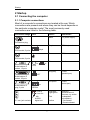
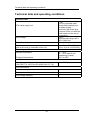
2.1.1 Computer connections
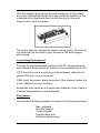
Most of a computer's connections are located at its rear. Which
connections are present and where they can be found depends on
the particular computer model. The most commonly used
connections are listed in the following table.
Connection image
Icon
Colour
Connection
Black
PC power supply
Purple
PS/2 keyboard
Green
PS/2 mouse
Blue
Monitor
Burgundy
Printer
(parallel port)
Turquoise
COM1
(serial port)
Light blue
Light green
Sound2)
(external sound
sources, e.g. active
loudspeaker,
microphone)
– Soundcard
- Sound onboard
1) 4)
Cold device plug
Keyb.
PS/2 socket, 6 pole
PS/2 socket, 6 pole
or
Subminiature D
socket, 15 pole
or
VGA
LPT
Subminiature D
socket, 25 pole
1
Subminiature D
plug, 9 pole
or
SERIAL
Line In
Line Out
3.5 mm jack sockets
Pink
Mic
AUDIO
digital out
Yellow
7
Startup
SPDIF IN
SPDIF Out
Yellow
Digital sound
connection
see also manual on
the motherboard and
"Tips and tricks"
Black
Connection for USB
2.0 devices (e.g.
keyboard, IR
sender/receiver
module, scanner,
printer) USB 2.03)
Cinch socket
or
USB socket
white
USB
Black
white
Connection for IEEcompatible devices
(e.g. video recorder,
digital video camera)
FireWire
None
Modem
None
Network or DSL
modem
CATV
None
Cable, antenna
connection
SVIDEO IN
SVIDEO OUT
Black
Video input and
output connection
or
FireWire socket
IEEE 1394
or
RJ-11 socket
or LINE
or PHONE
or
RJ-45 socket
or LAN
Antenna socket
4-pole or more
socket
(see documentation
about the VGA/TV
card)
SPDIF
Black
Digital optical sound
connection
Green
WLAN operational
display Operational
display only
functions correctly
when WLAN is
installed.
optic
● LED
WLAN LINK
8
Startup
1)
Caution: Under the connection, there may be a toggle switch for changing the
power supply from 230 V to 115 V. The factory setting is 230 V .
2)
With an additionally installed soundcard, the sound function on the motherboard is
not activated or "Sound onboard" is not available.
3)
Important information on USB 2.0: In order to guarantee a reliable data transfer
rate, we recommend that you use USB connecting cable with a maximum length
of 4 m.
4)
Controls on the power supply (optional)
Mains on/off switch
1
0
230
Voltage selector
115
optional
Caution!
Please note the mains power supply to which your computer is to be
connected and compare it with the default setting.
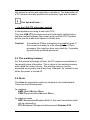
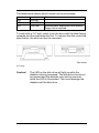
2.1.2 Connections, controls and indicators on the front of the
PC
Connections
The descriptions of the various connections can be found in the
previous table.
Controls
Standby
button
Button to activate the standby function
and on/off for ATX systems.
Power LED on
The system is switched on (POWER)
Power button
The system is switched on when the blue
ring is illuminated
HDD LED on
Shows that the hard disk is being
accessed.
(HDD)
Indicators
or
9
Startup
2.2 Connection
Before you switch on the computer, please connect
1. the monitor, keyboard, mouse, printer (if applicable), modem
and any other peripheral units to the PC. Please refer to the
information in the chapter "Computer Connections", as well as
the information in the "Quick Guide".
2. First connect the power cable supplied to the power socket on
the PC and then plug it into a 230 V or 115 V power socket
(plug strip). You may only operate the unit if its rated voltage
matches the local mains voltage. If your computer has a
double-voltage toggle switch, please ensure that it has been
set to the correct mains voltage for your country. The
manufacturer’s default setting is 230 V.
After cabling
3. Turn on your monitor.
4. Then, if applicable, switch on the on/off switch on the back of
the computer. To start the computer, press the standby button
located on the front of the computer.
The computer is ready for operation when the green lamp / blue
ring is illuminated.
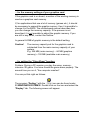
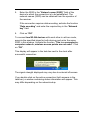
2.3 Initial startup of preinstalled software
Your computer has Microsoft®Windows XP Home Edition preinstalled as standard. After turning on the computer, it is ready to
use. You can use the Windows operating system immediately. You
may have to make some adjustments. Follow the on-screen
instructions.
You can find the pre-installed software under: "Start / All
Programs".
10
Startup
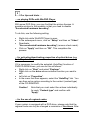
Note on Microsoft®Windows XP Home Edition and
Professional
Fujitsu Siemens Computers has pre-installed Microsoft®Windows
XP in such a way that you can use the product immediately. If you
want to change critical hardware components, it may be necessary
to reactivate the system. In this case, follow the program
instructions after changing the hardware. In case of any queries,
please contact our Help Desk (www.fujitsu-siemens.com/service).
Note on Microsoft®Word
Microsoft has provided user activation for Microsoft®Word. Follow
the program instructions after starting the program. In case of any
queries, please contact our Help Desk (www.fujitsusiemens.com/service).
11
Transporting the system
3 Transporting the system
If you are going to transport your computer over a long distance,
for example in a vehicle, you must ensure that the data carriers are
not at risk of being damaged by the transport. When transporting
the computer in a vehicle, always make a complete backup of the
hard disk on an external data carrier.
If you are transporting the PC only a short distance, i.e. only to
another room or to a different desk, a backup need not necessarily
be carried out. However, you must make sure that the unit is
transported carefully.
For the onward shipment of the product or other transport, use the
original packaging or other suitable packaging which provides
protection against shock and impact.
Detach all external cable connections and transport all devices
separately and only in their original packaging or in other suitable
packaging which guarantees protection against shock and impact.
Do not drop the device and do not expose it to severe vibrations.
CAUTION! The computer should ideally be transported in the
original packaging which has been specifically
designed for this purpose.
We only use recyclable material to package our units.
12
Guarantee services
4 Guarantee services
For our systems we generally grant guarantee claims according to
the German Civil Code as well as additional guarantee services on
agreement (see the corresponding service documentation for
details).
The system you have purchased has been produced to
environmentally sound standards and strict quality standards by
our company, which is certified to DIN ISO 9001 and DIN EN ISO
144001. We provide a statutory guarantee on all of our products, or
an extended warranty by arrangement.
5 Return of old units
The offer of taking back and recycling our systems is regulated and
guaranteed by our environmental management which has been
certified according to DIN EN ISO 14001.
As far as possible, our devices are produced from materials which
can be appropriately recycled. After use, the device is taken back
for re-utilisation or recycling of the materials, insofar as it is
returned in a state corresponding to proper use. Non-recyclable
device components are disposed of appropriately.
To return a device, please use the recycling and disposal facilities
available in your country.
Further information about country-specific recycling and disposal
facilities can be found on the Internet at:
www.fujitsu-siemens.com/recycling
If you have any other questions about disposal, please contact
your sales agent or our Help Desk.
13
Technical data and operating conditions
Technical data and operating conditions
Technical data
≤5W
(0 W only possible when
directly disconnected from
the power supply –
disconnect the power plug
or switch off the unit with the
on/off switch on the rear of
the housing)
230 V~
(optional wide range 100 V240 V 50/60 Hz)
50 Hz (60 Hz)
Power drain when unit is switched off –
ATX mains supply unit
Input voltage
Rated frequency
Rated input current (corresponds to details on the
label on the rear or underside of the unit)
Operating conditions
4 A or 5 A at 230 V/50 Hz
(9 A or 10 A at 115 V/60 Hz)
Ambient temperature
10 ... 35°C
20 ... 85% relative noncondensing humidity
-25°C to 60°C
Transport temperature
Loudness
Sound power level
max. 55 dB (A)
(DIN EN27779, ISO3744, ISO 9296, RAL UZ -78)
Unit classification
Protective rating
I
Faulting class
2
Over voltage category
II
A-1
Supplement to the operating instructions
Supplement to the operating instructions
Guidelines and Environmental Protection
An important characteristic of our products, alongside quality and
performance, is environmental friendliness.
(I)
Protection of resources with energy-saving functions
Our units generally have energy-saving modes.
(II)
Device safety
The units meet the requirements of the low voltage directive
73/23/EEC including the amendment 93/68/EEC, certified in
accordance with EN 60950, and the directive on electromagnetic
compatibility 89/336/EEC including the amendment 93/68/EEC.
(III)
Guarantee of electromagnetic compatibility
All data and signal cables must be provided with sufficient
shielding. The minimum requirement is a Category 5 shielded
cable for 10/100 Ethernet, or Category 5e for Gigabit Ethernet. As
described in the operating instructions, all of the housing parts
must be installed.
−
Requirements for work with monitors
Our units meet the requirements set for work with monitors in
accordance with the EU screen directive 90/270/EEC for the
purposes of the EU directive 89/391/EEC.
−
Lasers
If your system has an optical drive such as a CD-ROM, CD-RW,
DVD or combined drive, the following applies:
With closed PC housings, the optical drives used correspond to
laser class 1 in accordance with IEC 60825-1. These contain lightemitting diodes (LED) which under some circumstances may
generate a stronger light beam than laser class 1. A direct glance
into this beam, even with protective eyewear, is dangerous and
may lead to injury. Therefore, no parts of the optical drive housing
are to be removed.
A-2
Supplement to the operating instructions
−
Operating Instructions
The documentation delivered with the unit has been printed solely
on chlorine-free paper.
The documents mentioned above can be viewed at the
manufacturer if required.
A-3
i
Help with problems
and information,
frequently asked questions
1 Guidelines
1.1 EMC directives
Abbreviation for "ElectroMagnetic Compatibility". As well as the
effects of electrical smog on human health, the effects of electronic
devices and installations on other electrical systems are also an
important aspect of many discussions today. It is not without good
reason that the standards for electromagnetic compatibility (EMC)
have recently been drastically tightened in the area of computers
and radio networks.
1.2 CE directives
CE, the abbreviation for Communauté Europenne, indicates that
the product conforms with the directives, i.e. it is the
manufacturer’s confirmation that they have complied with the
requirements collected in the EU directives, particularly the
protection requirements for the manufacture of the product.
The CE mark on a product guarantees that the product may be
brought into circulation within the EU.
Since 1996, CE conformity has been legally binding. All electrical
and electronic devices must carry the CE mark, as must all data
networks and their passive components, such as cables, hubs etc.
st
From 1 January 1997, companies are no longer allowed to sell a
product without the CE mark. This has created a legal framework
where manufacturers have had to introduce technical measures to
ensure that computer systems meet the required "standards on
interference emission and resistance to interference". The housing
is an important aspect of this. Even high-quality structures cannot
guarantee compliance with the directives. To compensate for
interference emissions, measures include the use of magnetic
cores, to comply with the appropriate standards. Unused drive
slots are sealed with additional slot panels.
1.3 R&TTE directive and FTE law
The purpose of the law is to control the introduction into circulation
and the operation of radio equipment and telecommunications
terminals falling under the jurisdiction of the R&TTE directive, and
1
to allow the free movement of these goods within the European
internal market.
The directive, the RTTE directive 1999/5 EC (Radio equipment and
Telecommunications Terminal Equipment and the mutual
recognition of their conformity) has been implemented in German
law by the FTEG (Funkanlagen und Telekommunikations
Endeinrichtungs Gesetz – Radio equipment and
Telecommunications Terminal law).
The directive was published on 7.4.1999 in the EU Official Gazette
L91/1999 and was thus brought into law. The FTEG was
announced in the German Federal Law Gazette Part I, No. 6 on 7
February 2001, and came into force on 8 February 2001.
1.4 Low voltage directive
In accordance with the directive 73/23/EEC, appropriate
regulations have been binding since the seventies. In Germany,
this directive was brought into legal effect with the Device safety
law, the first prescription to the law on technical materials. Since 1st
January 1997, manufacturers have not been allowed to see
products without a CE mark.
The CE mark can be displayed if the product meets the safety
targets specified in the low voltage directive. In general, this means
meeting the technical requirements specified in a harmonised
standard. This directive is applicable for all electrical equipment
within particular voltage limits.
2
2 Hardware
Hardware is a very commonly used term in computer technology. It
simply refers to all the components of a PC and its peripherals
(e.g. printers, scanners etc.).
i
Our tips and hints …
... on saving energy
• We recommend connecting the system and the peripherals to
a standard switchable plug strip. This makes disconnecting the
entire system from the mains easier, safer and clearer.
• PC systems and peripherals that do not have a mains switch
and are connected to the mains are on "Standby" mode. Power
consumption is inevitable in this mode. In "Standby" mode the
system will maintain certain functions, e.g. wake on LAN, wake
on RING (MODEM). To isolate the system you will either have
to disconnect the mains plug or switch the system off at a plug
strip.
• If you will not be using the PC for a long period of time, or if
you will not be using the wake on LAN or wake on RING
(MODEM) functions, turn off the entire system.
2.1 The motherboard
The motherboard (also called the mainboard) is the most important
component of your computer. Among other things, it contains the
CPU, the working memory and slots for additional components.
You can find important and detailed information in the appropriate
manual. This is supplied electronically on the
"Drivers & Utility" CD/DVD or in printed form.
2.2 The CPU
CPU is an abbreviation for the term Central Processing Unit. The
CPU is the actual "brain" of the computer. It is responsible for all of
3
the system’s control and calculation operations. The description of
a PC system normally specifies the processor type and its speed.
i
Our tips and hints …
... on the LGA-775 processor socket
A few systems are using a new Intel CPU.
The new LGA-775 processor socket is technically configured so
that the contact between the socket (pins) and the CPU (contact
points) can be made with adjacent contact pins.
Caution!
Conventional 478pin processors may not be used. If
the current processor is to be changed to a 775pin
processor, this must be done very carefully, if possible
by technically qualified personnel.
2.3 The working memory
For the internal exchange of data, the PC requires somewhere to
temporarily store information. This is done in the working memory,
also called the main memory. The working memory can be
accessed very quickly and at any time. However, its content is lost
when the power is turned off.
2.4 Slots
The slots for expansion cards are located on the motherboard.
There are the following slots:
for modems
AMR (Audio Modem Riser)
CNR (Communication Network Riser)
for graphics cards
AGP (Accelerated Graphics Port) In the near future these slots
will be replaced by
PCI (Peripheral Component Interconnect) Express X16
4
for other cards, e.g. multimedia, TV card, modem, the
PCI slots are available. The trend is towards
PCI Express X1.
Slots for memory modules to equip the working memory, so-called
DIMM sockets (abbreviation for "Dual In-Line Memory Modules",
memory modules with two rows of contacts) are also components
of the motherboard. The memory banks can be equipped with the
following memory modules:
•
•
SD RAM, 168 pin (Synchronous Dynamic Random Access
Memory). This memory type synchronises itself with the
system clock, which controls the processor. This prevents
delays when accessing the memory. It works in
synchronisation with the external CPU clock.
R-DRAM (Rambus-Dynamic Random Access Memory) also
known as RIMM (Rambus Inline Memory Module). This
memory uses a special serial memory organisation, which was
developed by the company RAMBUS. With this principle, the
R-DRAM modules must be placed in pairs. Empty RIMM slots
have to be populated by so-called CRIMMs (Continuity RIMM).
The CRIMMs prevent an interruption in the signal lines, which
are a serial connection in a RAMBUS interface, and therefore
ensure that the direct RAMBUS channel functions correctly. If
you want to upgrade the system memory at a later date, you
can remove the CRIMMs and replace them with RIMMs.
When installing RIMMs, you must observe certain rules, in
order to achieve optimum system performance.
The RIMM slots are divided into two banks:
• Bank 0 (RIMM slots 1 and 2)
• Bank 1 (RIMM slots 3 and 4)
Bank 0 must always be populated first, in order to ensure that
RIMMS are installed in RIMM slots 1 and 2. The memory
configuration (speed, number of chips, size and density) of the
RIMMS installed in Bank 0 and Bank 1 must be identical.
•
DDR SDRAM, 184 pin (Double Data Rate Synchronous
Dynamic Random Access Memory). This memory type uses a
technology that works with both sides (flanks) of a clock pulse
5
to process data. This means that two memory access actions
are realised per clock pulse, thereby achieving double the
transmission rate.
With some memory modules, the configuration of the memory
banks is dependent on the motherboard’s chip set. Information on
this can be found in the motherboard documentation.
Detailed information about slots and the BIOS can be found in the
documentation for the motherboard.
2.5 The graphics card
The graphics card is a hardware component of the computer,
which allows information to be processed and displayed on a
monitor.
As digital data is used inside the PC, while traditional tube monitors
only work with analog signals, the fundamental task of the graphics
card is to convert the digital information from the PC into analog
signals for the monitor.
Recently, flat-screen monitors with DVI digital input (Digital Visual
Interface) have come into use. These devices process the digital
image signal directly in the monitor.
The essential components of a graphics card are the graphics
processor, the memory, the RAMDAC (Random Access Memory
Digital Analog Converter), the internal bus and the interfaces to the
motherboard, monitor and possibly a TV.
The graphics card is inserted in a specially designed AGP
(Accelerated Graphics Port) or PCI Express X16 slot on the
motherboard. The graphics card may also be integrated on the
motherboard ("graphic on board").
For low-fatigue work on the PC, it is important from an ergonomic
point of view that the refresh rate is set correctly. Even at high
resolutions, this should not be below 85 Hz.
6
Modern screen designs use the "Plug and Play" function to set the
optimum parameters automatically. To do this, they use the DDC
(Display Data Channel). If the monitor and the graphics card are
DDC-compatible, they exchange their information via the operating
system and adjust to one other optimally.
Please follow the instructions in your monitor’s user manual.
Games and graphics applications can take up a great deal of
memory. It is not only the speed of the CPU that is crucial for
problem-free running, but also the size of the graphics card
memory. The capacity of the available graphics memory is crucial
for the number of colours and their resolution that can be
displayed, as the colour information for the red, green and blue
(RGB) colour elements must be provided for each pixel. Graphics
cards with a low memory capacity only have a limited range of
colours. Essentially, the resolution of a graphics card depends on
the graphics card memory, the refresh rate and the colour depth.
The higher the resolution and colour depth, the lower the refresh
rate.
i
Our tips and hints …
... for setting the screen refresh rate (refresh rate)
Click on "Start" – "Control panel". In this menu click on "Switch
to standard view". Double click on "Display". Under "Settings",
click on "Advanced" and then on "Monitor". You can then set the
"Screen refresh rate".
... to change the graphics card
The broadband data bus "PCI Express" will be used with the
launch of the "Intel® 915P" chip set generation located on the
motherboard, which was developed under the code name
"Grantsdale". If your system is fitted with a PCI Express graphics
card, please note that you may only use PCI Express cards. AGP
graphics cards may not be installed as there are no AGP slots
available.
7
... for the memory settings of your graphics card
If the graphics card is on board, a section of the working memory is
used as a graphics card memory.
If, for applications that use a lot of memory (games etc.), it should
be necessary to expand the graphic memory, then it is possible to
change it in the BIOS. The motherboard manual describes how
you can change the memory capacity. If the process is not
described, it is not possible to adjust the graphic memory. If you
are still in any doubt, contact the Hotline.
In general 64 MB of graphic memory is the default setting.
Caution!
The memory capacity set for the graphics card is
subtracted from the main memory capacity of your
system.
E.g. 256 MB (main memory) – 64 MB (graphics
memory) = 192 MB (available main memory)
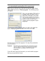
... for setting the "DirectDraw" function
Problem: During a PC session you play the same, memoryintensive 3D game. You have closed the game down properly. The
second time you run it, "the computer crashes".
You can put this right as follows:
icon can be found under
The program "Dxdiag." with the
C:\WINDOWS\SYSTEM32. Double click on the icon and select the
"Display" tab. The following screen will appear:
8
Deactivate the "DirectDraw acceleration" function.
... on connecting and the settings for a second screen output
device (TV, monitor)
If your PC is equipped with a second screen connection, this is
generally located on the rear of the PC; it can be that after a driver
is reinstalled the playback screen of the second output device
(monitor or TV) may be dark. This may happen if you have
downloaded and used a new driver version from the Internet. The
standard default for the driver is only configured for one screen
output device.
If you wish to use the second output, note the following from the
nd
user manual of the 2 device:
•
•
Which settings and which sockets do I need to use to run the
device as a monitor for example?
What television standard is for example the TV set to?
If the user manual is no longer available, contact your dealer or a
television specialist in your area.
Now proceed as follows to use the second output device:
• Switch the PC and both screen devices off. Connect the
screen devices to the PC. Turn the screen devices on, followed
9
•
•
•
•
by your PC, and then make the following settings on your
computer:
Right click on the desktop and then click on "Properties"
In the "Display properties" window click on "Settings" and
then on "Advanced".
The settings specific to the graphics cards will appear. One or
more tabs with the name of the VGA card installed will be
shown.
Refer to the documentation for the graphics card installed in
your PC for the advanced settings for two display devices. You
will find the documentation for your graphics card under:
"Start"- "All Programs" "Online Documentation" or
"Manuals".
In the documentation you will find a number of settings which will
enable you to work easily with two screens.
Note:
If your TV set model is too old or other settings have
been made, either no picture will appear or only a black
and white picture.
2.6 TV cards
The TV function in the PC is gaining in importance. If your PC is
already fitted with a TV card or if you would like to fit one in it, we
would like to inform you of a few basic details at this point.
The TV cards required for TV reception via a PC can be divided
into two groups – in analog and digital signal-processing modules.
Both modules are designed on the basis of the MPEG standard,
but differ in the signal processing. TV cards are also available as
combined versions.
MPEG is the abbreviation for "Motion Pictures Experts Group". File
formats and processes for compressing and saving video and
multimedia data (video, picture and audio data) in high quality were
and are being established by this organisation.
10
Analog TV cards
With analog television, the picture and sound information to be
transmitted is prepared according to a modulation process and
forwarded on in wave form in a medium such as air or via a cable.
This requires an analog TV card with analog antenna input.
Digital TV cards
A digital TV card is required to receive digital programmes via the
PC. The signal is transmitted according to the standard for the
compression of TV signals, MPEG-2 (Motion Pictures Experts
Group, 2nd standard).
The digital technology packs the data as binary code in data
packets which are then decoded again by the receiver. This
decoding is carried out by the DVB card in the PC.
There are three options for receiving digital television
− DVB-C (Digital Video Broadcast-Cable) reception via cable
− DVB-T (Digital Video Broadcast-Terrestrial) reception via
antenna
− DVB-S (Digital Video Broadcast-Satellite) reception via satellite
The reception quality is much better with DVB cards. As the digital
programmes are transmitted in MPEG-2 format, the TV programme
can also be processed directly on your PC hard disk.
A further difference is in the decoding of the MPEG stream.
Differentiation is made between TV cards with hardware MPEG
and TV cards with software MPEG.
•
•
With hardware MPEG, the processing power is undertaken by
a chip on the TV card. This means that there is practically no
involvement of the PC’s CPU. The majority of the CPU’s
processing power remains available for other applications.
With software MPEG, the CPU is responsible for the
processing power. Under some circumstances this may lead to
the CPU being noticeably overloaded.
11
i
Our tips and hints …
... on DVB-C reception via cable
Find out from your cable provider which programs you can receive
digitally.
... on DVB-T reception via antenna
This reception option is one of the most modern signal
transmission technologies for TV reception and is still not available
everywhere. Find out from your dealer or via the Internet whether
you have the option of using DVB-T television.
... on retrofitting
Before considering retrofitting, you must decide how you would like
to predominantly use your PC.
12
2.7 The soundcard
It is no longer possible to imagine many applications without
sound, e.g. DVD films, TV, games, Internet radio etc.
Soundcards convert digital signals into analog signals that can be
processed by speakers or amplifiers (DA converter). When
recording, e.g. with a microphone, analog signals are converted
into digital signals (AD converter).
The most important components of the soundcard are: Synthesiser
(sound generator), AD/DA converter (Analog Digital / Digital
Analog converter) for recording and playing back sounds.
Connections for headphones or speakers and a microphone are
integrated.
By default the output signal for sound playback is an analog
signal at the corresponding connection socket. In some
configurations, it is also possible to use the sound signal as a
digital signal. The SPDIF (Sony Philips Digital InterFace)
connection is available for this purpose.
There are two options for processing and playing back sound on
our PC systems:
• using a soundcard
• Sound on Board
Sound processing and playback using a soundcard
The soundcard is inserted into one of the PCI slots. In this
variation, the original manufacturer’s CD is normally supplied. This
CD contains the necessary drivers, programs and documentation.
Caution! If it is necessary to restore your system, you should
install the drivers and programs from the CD
accompanying the soundcard, as described in the
"System recovery" manual supplied.
13
•
Soundcard and SPDIF
You will be able to tell if SPDIF is available on the soundcard
by the cinch socket or the digital optical sound connection
labelled with SPDIF. If you want to use this signal, you will
need a speaker system with a decoder that can process digital
signals. With a digital optical sound connection you will require
a loudspeaker system with decoder which has digital optical
input. Make sure you follow the operating instructions for the
decoder.
•
Using the multi-channel audio function (optional) If you
want to find out more about the possibilities of multi-channel
sound, you will find the corresponding information in the
soundcard documentation.
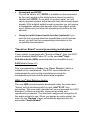
"Sound on Board" sound processing and playback
If your system is equipped with "Sound on Board", then the AC97
sound standard (Audio Codec 97) or the new Intel® High
Definition Audio (HDA) sound standard are available to you.
AC97(Audio Codec 97)
This is processed by a Codec chip (Coder Decoder) which is
located on the motherboard. The AC97 sound standard is
implemented by various chip manufacturers using the
corresponding drivers and the associated programs.
HDA (Intel® High Definition Audio)
The new HDA sound standard, developed under the code name
"Azalia" will be introduced with the new "Intel® 915P" chip
generation. This new audio standard will soon supersede the AC97
standard. It offers considerably improved recording and
reproduction properties. The automatic assignment recognition of
the audio sockets is new. When you assign an audio socket, the
menu for the "Realtek" player automatically appears with the
associated "Audio Wizard".
14
With this audio standard, the majority of the processing work is
assigned to the main processor. It is responsible for synthesiser
functions and mixes the digital data. The audio data is then
converted and sent to a Codec. This then converts the data into
audio signals.
In the recording direction, the Codec digitises the data and the
processor is then responsible for converting the data into
appropriate file formats and sampling rates. In the analog section,
Codecs are also responsible for the mixing of other inputs and
outputs such as those for the PC speakers, the microphone or the
CD player.
•
"Sound on Board" and SPDIF.
If sound is "on board", consult the motherboard description to
find out whether a connection for SPDIF is available on the
board. If you want to use this signal, you will need a speaker
system with a decoder that can process digital signals. Make
sure you follow the operating instructions for the decoder.
•
Using the multi-channel audio function (optional)
If your motherboard is equipped with an appropriate Codec
chip, you can use the multi-channel audio function. In general,
the drivers for the Codec chip are linked to a program, which
allows you to make the appropriate settings. If this function is
available, you will find the corresponding manufacturer’s
information in the motherboard documentation.
15
i
Our tips and hints …
... Example AC97 setting
Below, we illustrate how to make the appropriate settings
using the example of the "ALC 650" Codec chip for AC 97.
2. The following screen will
appear. You can then
select the language.
Confirm with "OK".
icon in
1. Click on the
the bottom right of the task
bar.
3. If you then select the "Speaker Configuration" tab, you can
activate the desired 2, 4 or 6-channel mode. This program
also shows the connections for the speakers.
4-channel
6-channel
16
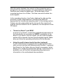
... Example of the HDA setting
When you use an audio socket, the menu for the "Realtek" player
automatically appears with the associated "Audio Wizard". The
socket in use flashes.
Fig.1: Front of the PC
Fig. 2: Rear of the PC
The appropriate socket can be configured here.
Fig. 3
Here you can select the audio
equipment which you have
connected to the front of the PC.
Fig. 4
Here you can select the audio
equipment which you have
connected to the rear of the PC.
Should a socket be incorrectly used, the system will direct you to
the right socket using an animated arrow (see fig. 5).
17
Fig. 5
... for testing the microphone connection
Some system configurations are supplied with an activated front
microphone connection as standard.
If the microphone connection is not working, you should check
whether the microphone connection is activated.
• Right click on the "Speaker icon" in the "Task bar".
• Click on "Adjust audio properties". "Sound and audio
equipment properties" appears.
• "Recording control" appears under "Voice" – "Voice
recording" – "Volume". Check whether the microphone is
activated.
• Close "Recording control" and click on "Test hardware".
Follow the instructions for the test.
... for changing the microphone connection from a front
microphone connection to a microphone connection on the
back of the PC
If you want to make use of the option of using the microphone on
the rear of the PC, the procedure is as follows:
•
•
•
Double click on the "Speaker icon" in the "Task bar".
In "Playback control" / "Volume control", click on "Options".
Activate "Advanced controls". Click on "Properties" in this
window. Select "Recording" and confirm with "OK".
Under "Microphone", go to "Advanced". "Advanced controls
for microphone" appears. In this window, deactivate "Mic 2
18
Select" or "Alternative microphone" and close the open
window.
This setting activates the microphone connection on the rear of the
PC. (if necessary test as above)
2.8 Modem and ISDN card
MODEM
Modem is an abbreviation for "MODulator/DEModulator". The
modem is a remote data transmission device, which
•
establishes a connection to a remote station,
•
converts (modulates) signals coming from the computer into
sounds,
•
sends these to the remote station,
•
and, used on the other end of the line, reconverts
(demodulates) the sounds received into machine-recognisable
signals.
There are countless standards – protocols – for modems to ensure
that they can communicate with one another. These standards are
defined by the CCITT (Comité Consultatif International
Télégraphique et Téléphonique).
The most recent analog modem standard V.92 was confirmed by
the ITU (International Telecommunication Union). Downstream
communication is unchanged at 56 kbit/s. The three most
important improvements compared to the V.90 standard that is
widely used today are:
•
•
•
Upload at up to 48 kbit/s possible (only 33 kbit/s with V.90)
Faster connection setup
Supports the "modem on hold" function. This means that
when you receive a telephone call while online, you will be
notified. The modem function will be "parked" and you will be
able to return to your Internet function once you have
completed your phone conversation.
If you want to use this standard and your modem is compatible
with this standard, then find out from your provider whether they
support V.92.
19
i
Our tips and hints …
... for setting the country code
When dialling country and area codes, WindowsXP uses the
settings that are entered under "Telephony" in the Control Panel.
After installation of Windows a country, e.g. "United Kingdom", may
already be entered under Location/Country. This may lead to
wrong numbers being dialled when using the modem. Before using
your modem for the first time, you should therefore change this
setting to the country in which you are running the PC and by
entering the appropriate number under "Area code".
For example, for the United Kingdom, the procedure is as follows:
• Open "Start" / "Control Panel" / "Printers and other
hardware" / "Telephone and modem options".
• Select the "Dialling rules" tab, by double clicking on "New
location" under Location. "Edit location" appears.
• Under "Country/Region" select "United Kingdom" and enter
your local area code under "Area code", then click on "Apply"
and confirm with "OK".
ISDN
ISDN is the abbreviation for Integrated Services Digital Network.
ISDN cards are used to establish a data connection between any
two compatible terminals. In contrast to a modem, these terminals
(ISDN cards) work on an exclusively digital basis (no
modulation/demodulation). Data transmission takes place on two
channels, each at 64kbit/s. These channels are known as B
channels. A further channel known as the D channel is responsible
for the exchange of control signals for the transmission terminals.
20
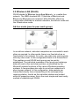
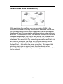
2.9 Wireless LAN (WLAN)
WLAN stands for Wireless Local Area Network, i.e. a cable-free
network. The IEEE standard 802.11(Institute of Electrical and
Electronics Engineers) for wireless LANs (WLANs) offers two
configuration methods for wireless networks, the ad-hoc mode and
the infrastructure mode.
Ad-hoc mode (peer-to-peer work group)
In an ad-hoc network, individual computers are connected to each
other as required. In other words, there is no fixed structure or
fixed points in the network. As a rule, any node may communicate
with any other node. In this configuration there is no AccessPoint.
This enables a small WLAN work group may be quickly
established. The individual members of the group can exchange
data with each other and share printers, as permitted by the
Microsoft network functions of the various Windows operating
systems. A few providers also refer to an ad-hoc network as a
peer-to-peer network. In this configuration, data packets are
transmitted directly from a transmitting to the corresponding
receiving station. Insofar as the individual stations are located
within its respective range, this is the most simple and least costly
method of establishing a WLAN.
21
Infrastructure mode (AccessPoint)
With a wireless AccessPoint your can operate a WLAN in the
infrastructure mode. You may then connect a wireless connection
to several wireless devices within a specified area or the range of
the AccessPoint. Communication with the wireless nodes is via an
antenna. In infrastructure mode, the wireless AccessPoint converts
the data transmitted in the form of radio waves into Ethernet data
and thereby forms the bridge between the individual wireless
clients and the wired LAN. By connecting several AccessPoints via
an Ethernet backbone, the range of a wireless network can be
expanded. If a mobile device falls outside the range of an
AccessPoint, it falls within the range of another. This means that
wireless clients can be moved freely from the domain of one
AccessPoint to the next, thereby maintaining a wireless connection
to the network.
22
i
Our tips and hints …
... on establishing WLANs
Checking the hardware and drivers
Switch your WLAN adapter on. The operating instructions for your
device will tell you where to activate the WLAN function.
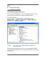
Proceed as follows:
Click on "Start" > "Control Panel" > "Performance and
Maintenance" > "System" > "Hardware" > "Device manager".
Double click on Network adapter.
Caution!
The name of the WLAN adapter may differ from
device to device.
Should a yellow exclamation mark or a red cross appear against
the listed WLAN adapter, there is a resource conflict or an incorrect
configuration.
23
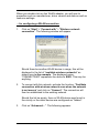
When you double click on the WLAN adapter, you will see its
properties such as manufacturer, driver version and date as well as
resource settings.
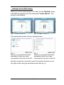
... for configuring a WLAN connection
1.
Click on "Start" > "Connect with" > "Wireless network
connection". The following window will appear.
Should there be another WLAN device in range, this will be
displayed in the list of "available wireless networks" as
shown here in the example. The displayed name
"CONNECT2AIR" represents the device’s SSID. This may be
anything.
2.
To connect with this network, activate the function: "Facilitate
connection with wireless network even when the network
is not secure" and click on "Connect". The connection will
then be established to the existing network.
Should the list be empty, then no WLAN device was found in
the vicinity or the other device was configured as "hidden".
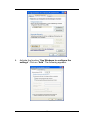
3.
Click on "Advanced…". The following appears:
24
4.
Activate the function "Use Windows to configure the
settings". Click on "Add“. The following appears:
25
5.
Enter the SSID in the "Network name (SSID)" field of the
device to which the connection is to be established. The
network names (SSID) can be obtained from the operator of
the receiver.
If the connection requires data encoding, activate the function
"Data encoding" and enter the required key in the "Network
key" field.
6.
Click on "OK".
To connect two WLAN devices with each other in ad-hoc mode,
execute the specified steps for both devices and enter the same
SSID in this window. Activate the function "This is a computer-tocomputer network; wireless access points are not used". Click
on "OK".
This display will appear in the task bar next to the clock after
successful connection:
The signal strength displayed may vary due to external influences.
If you double click on the active connection (both screens in the
task bar), a window containing status information will appear. This
may differ depending on the network setup.
26
This completes the establishment of the WLAN connection.
2.10 Drives
Device, which can write and read storage media such as diskettes
or hard disks, in order to save data permanently, i.e. even after the
power is turned off.
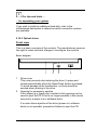
2.10.1 Floppy disk drive (optional)
Your computer is optionally equipped with a floppy disk drive.
A diskette is a thin, flexible plastic disc, which is coated with a
magnetic substance. This is then placed in a more or less stable
housing. Diskettes are also called "floppies" or "floppy disks".
They can be used to:
•
•
Transfer information from one computer to another and to
Create backup copies of the files and software on the hard
disk.
Standard floppy disk drives can read and write to 3.5” diskettes,
which can store up to 1.44 MB of data.
27
The table below shows which formats can be processed:
Comment
DD
HD
ED
720 KB
1.44 MB
2.88 MB
Motherboard dependent and special
floppy drive required
To work with a 3½" disk, insert it into the drive with the label facing
upwards and the read/write slot first. To remove the disk, press the
eject button; the disk can then be removed.
Eject button
3½" drive
Caution!
The LED on the disk drive will light up while the
diskette is being accessed. The disk drive should not
be opened and the diskette must not be removed
while the LED is illuminated. This could damage the
diskette and the disk drive.
28
2.10.2 Hard disk
The hard disk is a rigid disc, which is coated with a magnetic
substance and protected by a metal housing (hard disk drive). A
hard disk drive essentially consists of several discs, a spindle
motor, read/write heads and a device for positioning the head. The
hard disk is located inside your computer, but it can be exchanged.
Hard disks work in accordance with ATA (Advanced Technology
Attachment). This describes the protocol in accordance with which
the data is transported via the cables. ATA is a drive specification
for hard disk connections defined by ANSI (American National
Standard Institute).
There are two types in our PCs:
•
•
For hard disks, the widely used IDE (Integrated Drive
Electronics) connection standard (40-pin) is used on the
motherboard. The IDE connection is also called PATA (Parallel
ATA). This standard PC interface is primarily used for optical
drives and hard disks.
Another connection option for hard disks is the use of the
SATA (Serial ATA) interface (4-ping), if this is available on the
motherboard.
The hard disk is your computer’s main storage medium and you
can make your work easier and more productive by copying your
applications and files onto your hard disk. You can copy files to the
hard disk or delete them from it as often as you want.
The hard disk drive should be handled with great care, as it is very
sensitive.
29
i
Our tips and hints …
... for expanding your system
If you wish to install an additional hard disk, refer to the
motherboard description to determine which connection options
are available.
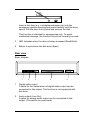
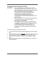
2.10.3 Optical drives
Front view
This is a basic overview of the controls. The manufacturer reserves
the right to make technical changes / reconfigure the controls.
Basic diagram
2
1
1
2
3
4
Drive cover
This cover prevents dust entering the drive. It opens and
closes automatically when the Open/Close button is pressed.
To avoid damage to the mechanism, no force should be
exerted when pushing in the drive.
Opening for emergency ejection
A thin object (e.g. paper clip) inserted in this opening can be
used to eject the CD if this is no longer possible in the normal
way due to a power cut or software block.
If a motor-driven ejection of the drive (power cut, software
block) is not possible, proceed as follows to eject the CD:
30
Insert a thin item (e.g. a straightened paper clip) into the
emergency ejection opening and press carefully until the drive
opens. Pull the drive out by hand and remove the disk.
This function is intended for emergencies only. To avoid
mechanical damage, this function should not normally be used.
3
LED Indicates when the drive is being accessed (Read/Write)
4
Button to open/close the disk drive (Eject)
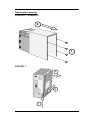
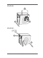
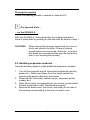
Rear view
Basic diagram
1
2
3
4
5
1
Digital audio output
A cable for the transmission of digital audio output can be
connected to this output. This function is not supported with
this drive.
2
Audio output (Line Out)
A cable for analog audio output can be connected to this
output. (Connection to sound card).
31
3
Jumper
The CD-ROM drive is configured via jumpers. These determine
how the device will be addressed by the IDE controller. If the
jumper is set to Master, the device works in Master mode, to
Slave in Slave mode. If the jumper is set to CSEL, the device
can be controlled with the help of the CSEL interface signal
(Cable SELect).
CSEL
Master
Slave
4
IDE connection
This socket is used for the connection of a data/control cable.
This 40-pin ribbon cable connects the CD-ROM drive and the
IDE controller.
5
Power supply connection
The power supply cable will be connected to this socket.
Types
There are different types of optical drives:
CD-ROM drive
CD-RW drive
DVD drive
DVD+RW drive
DVD ±R/RW drive
DVD+R9 or DVD+R DL drive (double layer)
DVD/CD-RW drives
32
CD/DVD data carriers
The CDs/DVDs available in the market correspond to different
standards. Not every CD/DVD can be read by every optical drive.
CD-ROM
Abbreviation for “Compact Disk - Read Only Memory”. A CD
ROM is a CD storage medium, on which up to 700 Mbytes of
digitised data is stored. However, this data cannot be changed
and can only be read by an optical drive. In principle, CD-ROMs
are read in the same way as audio CDs but cannot be used in
audio equipment.
CD-R
Abbreviation for "Compact Disk Recordable". A CD-R can only
be written once. Once a CD-R has been finalised, it is no longer
possible to delete or edit the content of the CD-R.
CD-RW
Abbreviation for "Compact Disk ReWritable". A CD format that
allows you to write to a CD any number of times using a CDRW drive. You can then read the information as often as you
wish. The CD-RW can be compared to a floppy disk, as it can
be used for the repeated storage of data.
Not all older optical drives can read CD-RWs.
DVD
Abbreviation for "Digital Versatile Disk" or "Digital Video Disk".
A DVD is a storage medium, similar to a CD, but with a higher
memory capacity, which is achieved by narrower tracking. A
DVD can be used in two positions, and on both sides
(depending on the type), which means that the memory
capacity can be 25 times that of a CD.
Because of the high memory capacity, DVD is particularly well
suited for digitised films with additional features such as
different languages or subtitles.
For DVD films, so-called regional codes were introduced in
1997, which are intended to prevent e.g. US DVDs from being
33
able to be played on European equipment and vice versa. For
this purpose, the world was divided into six regions:
1.
2.
3.
4.
5.
6.
USA, Canada
Japan, Europe, Middle East, South Africa
South-east Asia
Australia, South and Central America, New Zealand
Africa, former USSR, India
China
DVD drives resemble CD-ROM drives and are downwards
compatible, which means that they can also read CD-ROMs,
CD-RWs and audio CDs.
DVD+RW drive
Like CD-RW drives, DVD+RW drives can both read and write
storage media. Rewritable (RW) DVD+RWs are used. At 4.7
GBytes, DVD+RWs offer a memory capacity equivalent to
around seven times that of a normal CD-ROM.
For the user, these drives make it possible to transfer and
archive their own VHS videos, record their own videos using a
digital video camera or save data quantities that are too large
for CD-ROMs.
DVD ± R/RW drive
These drives enable you to use both recording processes
(DVD+R/RW, DVD-R/RW).
DVD+R9 or DVD+R DL drive (double layer)
(Digital Versatile Disc + Recordable 9 Gigabytes)
These drives are equipped with the new double-layer DVD
recording technology. The writing of a second layer onto the
DVD blank doubles the maximum data capacity from the 4.7
GB of conventional DVDs to 8.5 GB on a one-sided DVD.
34
i
Our tips and hints …
... on playing DVDs with WinDVD Player
With some DVD films, you may find that the picture freezes. A
possible solution to this problem is that you need to disable
"Accelerated hardware decoding".
To do this, use the following setting:
•
•
•
•
Right click while WinDVD Player is open.
In the subsequent menu, click on "Setup" and then on "Video".
Deactivate:
"Use accelerated hardware decoding" (remove check mark).
Click on "Apply" and then on "OK". This completes the
process.
... for activating/deactivating properties of optical drives (e.g.
AutoPlay function)
If it is necessary to modify the autostart (AutoPlay) function of
DVD/CD-ROM drives, you can do this as follows:
• Right click on "Start" and select "Explorer".
• Right click on the drive whose autostart function you want to
edit.
• Left click on "Properties".
• In the menu that then appears, select the "AutoPlay" tab. You
can then set an action according to the content (content type)
of the CD-ROM/DVD.
Caution!
Note that you must select the actions individually
for each "Content type" and confirm with
"Apply".
... for the use of regional codes
If your system is equipped with a DVD drive, please note that the
regional code can only be changed a maximum of five times. After
35
the fifth time, the code is retained as a permanent code; you
should therefore be careful about changing it. If you set the same
regional code as in the last installation, this is not registered as a
change. This process is determined on the hardware side and
cannot be cancelled using software.
Before buying a DVD video, you should check that the regional
code on the DVD video matches the code set on your PC.
... for using the correct blank DVDs
There is not a general standard for burning (writing) DVDs
currently. The most common recording methods for DVD burners
are: DVD+RW, DVD-RW and DVD-RAM. Although the
technologies are similar, each of these formats requires specific
blank DVDs and is based on a separate recording technology.
With most burning programs, you can find out under "Properties" or
"Infotool" which blanks can be used.
We recommend that on systems with Fujitsu Siemens Computers
DVD burners, the following blank DVDs be used:
DVD+RW rewritable blank DVDs or
DVD+R non-rewritable DVDs.
36
3 Software
3.1 General Information
Software is a chain of logic operations that tells the hardware,
which operations are to be executed. These logic operations are
known as programs. These programs consist of commands and
instruction sequences. These are processed electronically in bits
and bytes.
A bit is the smallest unit of electronic information. As it is very
complicated to handle individual bits, 8 bits are combined in a byte.
The byte is the basic unit of measurement in the computer world.
i
Our tips and hints …
... for data backup
•
•
Create backup copies of your work files on a regular basis.
This is the only way to protect against data loss, e.g. in the
event of a hard disk fault.
No liability shall be accepted for loss of data.
... for installing programs
Before installing new programs, close all applications.
After installing programs, you should always restart your computer,
even if you are not prompted to do so.
... for installing programs with and without the Autostart
function
The fact that the Autostart function is not active can be due to
Properties having been automatically edited when installing
programs, e.g. a burning program or DVD player. If the Autostart
function is activated, system errors may occur under certain
37
circumstances when blank CDs are inserted. Leave the Autostart
function for the CD-RW drive (burner) deactivated.
... for driver installation when restoring your system
If you should need to re-install your system, we urgently
recommend that, as far as possible, you backup all files before
complete reinstallation.
If you have carried out your complete reinstallation using the
"Product Recovery CD ROM" and the "Drivers & Utility CD/DVD",
as described in the general user manual, and one of the
components of your system is still not working, you can put this
right, provided that it is a driver problem and there is no
mechanical damage.
To do this, proceed as follows:
•
•
•
•
•
•
•
•
•
•
•
Insert the "Drivers & Utility" CD/DVD in the appropriate drive.
After the CD/DVD auto-starts, the "Fujitsu Siemens Help
Center" appears. Close this with "Exit".
With the "Drivers & Utility" CD/DVD inserted, click on "Start".
Right click on "Desktop".
Click on "Properties". "System properties" appears.
By clicking on "Hardware" you can open up the "Device
manager".
The "Device manager" shows an overview of your computer’s
hardware. This is where you can update the drivers (or the
software) for hardware devices or change the hardware
settings.
The faulty driver is normally indicated by a yellow question
mark (?).
Right click on this line.
Select "Update driver" in the menu that appears.
Continue with "Install software automatically
(recommended)" and confirm with "Next".
If necessary, follow the instructions on the screen.
38
... for automatically opening files of the same format
Right click on a file icon (e.g. with the file extension .jpg). Select
"Open with" and click on "Select program". The following screen
will appear:
Here, you can assign a file type to a
program which you want to use to
open files of that type. If you want
this file type to always be opened
using the selected program, use the
mouse to enter a check mark in
"Always use this program to open
these files".
If the following screen appears when you open a file, select the
option "Select program from list" and confirm with "OK".
The first screen shown then appears. You may then proceed as
described above.
Caution!
Only file types supported by the selected program
may be opened. Consult the appropriate program
documentation for details of the file formats
supported.
If you still cannot open the document, you must install a program
that can process that file format.
39
3.2 The operating system
The operating system is the "organiser" of your computer; the
operating system coordinates all functions e.g. for the graphics
card, the soundcard, the modem the network card and the external
devices using drivers.
If your operating system should fail to start, or if faults should occur
on your hard drive, it may be necessary to reinstall the pre-installed
software.
Computers from our company are supplied with a pre-installed
"Microsoft® Windows® XP Home Edition" operating system as
standard.
On your PC, you can find the registration code label as proof of the
legitimate purchase of the "Windows XP" operating system. This
registration code is not necessary for any reinstallation variation of
the operating system, as it is a BIOS-locked OEM version. You
should therefore only use BIOS versions that have been certified
by Fujitsu Siemens Computers.
With the BIOS-locked OEM version, which you have purchased
with your Fujitsu Siemens computer, it is not necessary to activate
the "Windows XP" operating system. Registration is optional. For
details, see the manual "Microsoft® Windows® XP Home
Edition - Getting Started".
In case of a problem, you can restore the system to its status on an
earlier date, without losing personal data files (e.g. documents,
Internet favourites and e-mail). Windows XP system recovery
monitors changes to the computer and generates easily identifiable
recovery checkpoints on a regular basis. These recovery
checkpoints allow you to restore the system to its status at an
earlier point in time.
40
i
Our tips and hints …
... for creating a restore checkpoint
•
•
•
•
Click on "Start"/"Control Panel"/"Performance and
Maintenance" and then on "System recovery".
Select the option "Create recovery checkpoint" and then click
on "Next".
In the field "Description of recovery checkpoint", enter a
name to identify this recovery checkpoint. The system recovery
automatically adds the date and time when the checkpoint was
created to this name.
Click on "Create" to complete this process.
... for restoring the system to a previous status
•
•
•
•
Click on "Start"/"Control Panel"/"Performance and
Maintenance" and then on "System recovery".
Select the option "Restore computer to a previous point in
time". Confirm with "Next". The checkpoint can be selected in
the subsequent screen.
If you have any questions or require further help, you should
use the comprehensive "Help and Support Center", by
clicking on the question mark in the top right of the screen.
You can also create and name your own recovery checkpoints
at any time.
41
3.3 BIOS
BIOS is the abbreviation for "Basic Input Output System". The
BIOS is the hardware-specific core of an operating system, which
is not deleted when the system is turned off and is located in the
EPROM. Data is written to this chip once, can only be read by the
computer, and can only be changed at a later date using special
programs (Flash-BIOS). Each time the computer is turned on, the
BIOS first of all runs a self-test. The computer then uses the BIOS
to start the operating system and to control the stream of data
between the hard disk, graphics card, keyboard and printer, until
the operating system takes over this task.
i
Our tips and hints …
... for using the BIOS
The BIOS is tailored to the specific demands of the system by the
manufacturer. Therefore, only the BIOS approved and certified by
the manufacturer should be used.
Current BIOS updates can be found at: www.fujitsu-siemens.com
... accessing the BIOS
In its delivery state, the BIOS is optimised such that a very short
boot time is achieved. To access the BIOS setup, immediately after
switching on the machine, i.e. during the boot process, press the
key to call the BIOS several times at short intervals until the BIOS
main menu appears on your screen.
Note:
Further information on setup and which key you must
press (e.g. F2 or Del) can be found in the motherboard
documentation.
42
3.4 Drivers
Drivers are programs, which allow interaction between the
computer, operating system and other components. It is therefore
important to install the correct component drivers for the correct
operating system.
The drivers we have tested are coordinated with the component
manufacturer and tailored for the system supplied and are normally
found on the "Drivers & Utility" CD/DVD or on an enclosed Drivers
CD-ROM/diskette.
43
44
3.5 INTERNET
The Internet is the world’s largest computer network, and consists
of many individual networks linked to one another. The features or
"services" of the Internet include electronic mail (e-mail) and file
transfer (FTP).
When using Internet services, it is important to use antiviral
software and to update it regularly.
i
Our tips and hints …
... for establishing a connection to the Internet
You can establish an Internet connection with the help of a
CD/DVD provided by an Internet service provider or without the
help of a CD/DVD.
If you are establishing an Internet connection through a provider,
insert the provider’s CD/DVD into the CD/DVD drive and follow the
on-screen instructions.
To establish an Internet connection without a CD/DVD, you must
obtain the dial-up number of the provider which you wish to use,
the user name and the password. Then proceed as follows:
•
•
If no previous Internet connection has been set up on your PC,
click on: "Start"; "Control Panel", "Network and Internet
connections", "Establish or create own Internet
connection". In the "Internet properties" screen click on
"Setup". The "New Connection Wizard" will appear. Follow
the setup procedure here.
If an Internet connection is already set up on your PC, you can
set up an additional provider using "Start" - "All Programs" –
"Accessories" – "Communications" – "New Connection
Wizard". Follow the setup procedure here also. Having an
additional Internet service provider means that you can benefit
from using the cheaper usage times of the different providers.
45
... for using antiviral software
Fujitsu Siemens Computers systems are always supplied with preinstalled antiviral software. If you have completely set up the
antiviral software and you decide to purchase another piece of
antiviral software, you must always uninstall the fully installed
antiviral software properly first. Otherwise, installation of a second
piece of antiviral software without previously uninstalling the
existing software may be successful but could lead to severe
software conflicts.
46
4 Peripherals
Peripherals are external components of the computer, i.e. devices
connected to the PC such as monitor, keyboard, printer, etc..
4.1 Keyboard
4.1.1 Keyboard areas and important keys
The keyboard is the "actual" interface between the user and the
computer. It is used to input commands. It is similar in design to a
typewriter, but has a few more keys.
Adjusting the keyboard
The keyboard may be positioned flat or gently inclined to suit
individual needs. If you look underneath the keyboard you will find
two feet which can be pulled out to adjust the keyboard.
Wrist support
If your keyboard has a wrist support, please fix it to the keyboard.
Depending on the keyboard type, this may be done in one of two
ways:
With the curved design place the wrist support in front of the
keyboard and push in the direction of the arrow until it slots into
place.
47
With the straight design place the wrist support on a flat surface
and press the keyboard down from above with the notches on the
underside of the keyboard lined up with the pins on the wrist
support until it slots into place.
The wrist support is intended for breaks during typing. You should
not therefore rest the balls of your thumbs on the wrist support
while typing.
Connecting the keyboard
Connect the keyboard before turning on the PC. Keyboards may
have different plugs with which they are to be connected to the PC.
PS/2: Insert the round, purple plug of the keyboard cable into the
purple PS/2 port on your computer.
USB: Insert the square, black connector of the keyboard cable into
a free USB port on your computer.
Keyboards with cables do not require any batteries, even if there is
a battery compartment on the underside.
Key groups
The standard Windows keyboard consists of the following sections:
-
Main keyboard
Numeric keypad
Cursor keypad
Function keys and
Windows-specific keys
48
Main keyboard
The layout of the main keyboard essentially corresponds to that of
a typewriter keyboard. Pressing a key generates the corresponding
character and moves the cursor forward by one position. Most keys
have a repeat function, i.e. if you hold down the key, the entry of
that character is repeated. However, there are a few countryspecific keys (so-called dead keys) which do not cause the cursor
to move forwards when pressed.
A few PC-specific keys on the main keyboard are assigned special
functions:
The RETURN, ENTER key
<
>
This key is used to have the current command input executed by
the computer. After inputting a text line, pressing this key moves
the cursor to the beginning of a new line. Depending on the
program in use, the function of the <RETURN> key on the main
keyboard and <Enter> on the numeric keypad may be different.
The BACKSPACE key <
>
This key moves the cursor one space to the left and deletes the
last character.
The SPACE BAR <
>
Pressing this key moves the cursor one space to the right and
inserts an empty space at the same time. Please note that an
empty space is treated in the same way as a letter or number.
The TAB key <
>
In word-processing programs, this key is used to move the cursor
to the next tab stop. Depending on the program in use, the key
may also be used for other cursor movements or functions.
The SHIFT key < >
Two identical shift keys are located on the left and right sides of the
main keyboard. Pressing the shift key while simultaneously
pressing a letter or number generates the letter in upper case or
the relevant special character. In connection with the numeric
49
keypad, it is possible to toggle between cursor movement and the
input of numbers.
The CAPS LOCK key < >
This key is used to enter upper case letters. If this key is engaged,
the central LED ("Caps Lock" / "< >" / "A") is illuminated on the
keyboard. Pressing the CAPS LOCK key again reverses the lock
(depending on the operating system).
The <Alt> key
The function of this key is program-dependent. It is always used in
connection with other keys. Like the SHIFT key, when pressed
alone it generally has no function. In the operating system as well
as in many programs, special characters which cannot be found on
the keyboard can be entered with the aid of the ALT key and
commands can be generated.
The <Alt Gr> key
This key is used to enter the special characters shown on some
keys as a third option. E.g. if you wish to enter the "\" character,
hold down <Alt Gr> while also pressing the <ß> key.
The <Ctrl> key
This key is a control key. Like the ALT key it is only active in
combination with other keys. Its meaning varies from program to
program.
The <Esc> key
This is program-dependent. When working in the operating system,
the current prompt entered in the command buffer will be deleted.
Windows-specific keys:
These keys only exist on a Windows keyboard as they support
Windows-specific functions. The keys are:
1 stkey: between <Ctrl> and <ALT>, left side
2ndkey: between <Alt Gr> and <Ctrl>, right side next to <Alt Gr>
3rdkey: next to 2nd key
50
Description of the Windows-specific keys:
WIN key
Function
Description
1 st& 2nd key
<Ctrl> + <Esc>
Windows Manual Appendix
Key combinations
3rdkey
<Shift> + <F10> Windows Manual Appendix
Key combination
You can also work with this keyboard if you do not have Windows
installed. If this is the case, these keys have no function.
The numeric keypad
Number keys
The keys in this block have two purposes. Firstly, they represent
the numbers 0 to 9 and the comma, secondly the cursor control
functions. They can be switched from one function to the other
with the <Num Lock > key. Pressing it once switches from the
cursor control function to the numbers, pressing it again returns to
cursor control. The setting in use is indicated by the LED located at
the top left ("Num" / "Num Lock" / "1").
Numbers:
Cursor control:
The LED at the top left is illuminated.
The LED at the top left is not illuminated.
51
The <Ins> key
The <Ins> key is the Insert key. In the operating system mode,
characters on the screen can be replaced by being overwritten with
a new character. The <Ins> key can be switched to the insert
mode, and the newly entered characters are inserted at the cursor
position.
Please note that the use of this key may be program-dependent.
The <Del> key
The <Del> key is used to delete the character at which or before
which the cursor stands.
Programs may assign this key other functions.
Cursor keys
The keys in the cursor keypad and the correspondingly designated
keys of the numeric keypad have the same use. It is also possible
for programs to assign other uses to these keys.
< >
moves the cursor one line up
< >
moves the cursor one line down
< >
moves the cursor one character to
the right
52
<>
moves the cursor one character to
the left
<Home>
moves the cursor to the beginning
of the line or to the top left corner
of the screen
<End>
moves the cursor to the end of the
line or to the bottom right corner of
the screen
<Page Down>
moves the display one screen
page down
<Page Up>
moves the display one screen
page up
Function keys
The general function keys, labelled <F1> to <F12>, each have a
different use depending on the program being used. Their use in
the operating system is detailed in the associated manual.
The <Print Screen> key
Pressing <Print Screen> produces a copy of the content of the
screen.
The <Scroll Lock> /
key
The <Scroll lock > key is used to change the function of the
cursor keys. This is program-dependent. If the "Scroll Lock" mode
is activated, the LED ("Scroll Lock" /
illuminated.
) at the top right is
The <Pause/Break> key
Used by the operating system and a few applications.
53
Functions accessed by pressing several keys simultaneously
The following key combinations are used in the WINDOWS
operating system control panel; their function is to some extent
program-dependent:
<Ctrl> + <Alt> + <Del>
System reboot
Pressing the three keys simultaneously
aborts the current program and reboots
the operating system.
Caution: Data which has not been
saved to the main memory will
be lost.
<Ctrl> + <Pause>
Program halt
Simultaneously pressing Ctrl and Pause
aborts the current program.
<Ctrl> + <Home>
This key combination moves the cursor
to the beginning of a document.
<Ctrl> + <End>
This key combination moves the cursor
to the end of a document.
54
4.1.2 The multifunction keyboard
Multifunction keyboards have additional keys (multimedia keys)
which can be used to activate functions more quickly. The following
description of the keys applies for: Windows ME, Windows 2000,
Windows XP.
Previous track
This button can be used to skip back to the previous track in
the active play-back device.
Stop
This button stops the playing of a track.
Play/pause
This button is used to start playing a track as with a CD player
or to pause a track briefly.
Next track
This button can be used to skip to the next track in the active
play-back device.
Lower volume of loudspeaker
This button lowers the volume of the loudspeaker connected.
Turn loudspeaker on/off
This button turns the loudspeaker connected on and off
Increase volume of loudspeaker
This button increases the volume of the loudspeaker
connected.
E-mail
This button is used to access your system’s standard e-mail
program.
Web browser
This button starts your system’s standard browser.
Standby mode
The computer enters standby mode in accordance with the
BIOS and operating system settings.
55
4.1.3 Wireless keyboard
If your PC comes with a wireless keyboard, usually in combination
with a wireless mouse, please refer to the special instructions in
the accompanying manual.
Using the keyboard
The keyboard is configured for ergonomic and healthy working.
Awkward configuration of the input and output devices, incorrect
arm or seat posture and uninterrupted use of the keyboard or
mouse may lead to tension, tiredness and injury to the musculoskeletal system (nerves, muscles, tendons and joints). This risks
can be considerably reduced if you follow the advice below.
•
•
•
•
•
•
•
Arrange your workstation in accordance with the
recommendations for an ergonomic workstation in the PC’s
operating instructions.
Position the keyboard such that it can be operated without
noticeable burden. The keyboard should be arranged in
parallel to your upper body. This position facilitates a relaxed
shoulder and arm position.
The distance between the keyboard and edge of the desk
should be between 5 and 10 cm.
While typing, hold your hands and
lower arms such that they form
the most natural line possible. Do
not bend your hands too much to
the side.
Keep your wrists straight while
typing. Do not bend your hands up
or down. Adjust the tilt of the
keyboard to meet your individual
needs using the fold-out support on
its base.
While typing do not support your hands on the balls of your
thumbs and do not hit the keys too hard.
Relax your hands and wrists by taking regular breaks. During
these typing breaks you should support your hands on the
balls of your thumbs or rest your lower arms on the armrests. If
necessary, perform appropriate loosening exercises.
56
i
Our tips and hints …
... on the keyboard connection cable
Should your keyboard be equipped with a
keyboard where the connection cable and
the keyboard are delivered separately,
attach the
the circular 6-pin PS/2 plug (mini DIN
connector, purple) to the corresponding
socket on the PC, and
the square 6-pin keyboard connector to
the keyboard.
... on the functions of the keyboard
If you require further information about the functions of the
keyboard and want to access the menus for changing the settings,
the procedure is as follows:
•
•
Click on "Start" and select "Control panel".
Click on the icon or name "Keyboard" to open the "Keyboard
properties" dialog box.
Properties such as the refresh rate and cursor flashing rate can be
adjusted here to suit your working methods.
57
4.2 Mouse
The mouse is an input device which is guided by hand over a flat
and horizontal surface. The recording of the movement takes place
mechanically or optically. The mouse movement is analysed by the
computer and the cursor is moved accordingly across the screen.
At appropriate positions, the mouse buttons can be used to
activate actions such as inputs, opening and closing files or charts.
The two-button wheel mouse can be used as a two-button mouse
in all operating systems. Under Windows operating systems, you
can use the wheel by turning it to navigate within the application
window and as a third button by pressing it.
The symmetrically designed mice are equally suitable for righthanded and left-handed users.
Mice may have different plugs with which they are to be connected
to the PC.
PS/2: Insert the round, green plug into the green socket on the PC
before switching it on.
USB: Insert the square, black connector of the mouse cable into a
free USB port on your computer or a connected USB hub.
USB-PS/ adapter: Some mice have a green USB-PS/2 adapter.
Without this adapter, the mouse can be used in a USB socket, with
the adapter in the PS/2 interface. This adapter can only be used for
the mouse with which it was delivered.
58
i
Our tips and hints …
... ...for the function of the wheel mouse
If you require further information about the functions of the wheel
mouse and want to access the menus for assigning functions and
changing the settings, the procedure is as follows:
•
•
Click on "Start" and select "Control panel".
Click on the icon or name "Mouse" to open the "Mouse
properties" dialog box.
Here, you can adjust the mouse properties individually to match
your working methods.
... on using an optical mouse
The scanning system of an optical mouse works on many surfaces.
However, please note that heavily reflective or red surfaces may
cause faults.
... on using a mechanical mouse
Make sure that you use a mechanical mouse on a clean, flat
surface. The use of a mouse pad is recommended.
Clean the ball and the mechanical scanning system regularly.
Carefully remove the ball cover and take out the ball. This will also
provide access to the axes of the mechanical system for cleaning.
Carefully refit the parts in reverse order.
59
4.3 Monitor
A monitor is, of course, part of the PC. It is the visual medium of
communication between the user and the machine.
It is important that you follow the instructions relating to
ergonomics, which should be contained in the instruction manual
for the monitor. These include: Correct posture, correct distance
between the eyes and the monitor (approx. 50 cm), positioning of
the keyboard within optimum reach of the hands.
4.4 Printers
Printers are output devices, which can output electronic data in
paper form as a so-called print medium.
In order for the printer to receive the desired data from the PC, it
must be connected to the computer’s printer port. This port
normally has the designation LPT1. However, it is also possible to
communicate with modern printers via the USB port.
The printer setup program is a component of Windows. If you want
to connect a new printer to your computer, you must inform your
PC of this. The printer setup program helps you to install the driver
and informs Windows which new printer you have connected and
how the operating system selects it.
4.5 Scanners
Similar to a copier, a scanner makes a kind of electronic
photograph of a document. The scanner converts this "photograph"
to a file, which can be understood by a computer. A photograph is
thus turned into a digital image, which you can save as a file and
process using appropriate graphics programs.
60
5 Expansion of performance
5.1 Upgrading the system
Your system is of a modular configuration. This means that in
general you have the option of upgrading your system with various
components and modules (e.g. working memory, hard disk,
graphics card, etc.) obtainable from your specialist dealer or a
computer shop.
i
Our tips and hints …
... on component expansion
Before expanding your system, find out from the motherboard
description which components are compatible with your system.
For example, take note of:
• the working memory type
• the hard disk type to be used (SATA or IDE)
... adequate cooling
When upgrading your PC ensure that the components have
sufficient cooling. If your are unsure, contact a local computer
expert.
Caution!
Heat build-up in your system may lead to irreversible
damage and a risk of fire due to overheating of
system components.
61
5.2 Opening and closing the housing
CAUTION!
•
•
Only qualified personnel should open the PC.
Tampering with the unit will result in a loss of the
right to guarantee claims and the discontinuation of
the manufacturer’s guarantee obligation.
Compliance with the harmonised standards
according to the legislation regarding
electromagnetic compatibility of units and
compliance with the low voltage directive may be
interfered with.
When opening the PC it must be ensured that you
do not use any force and that no locking
mechanisms are damaged.
All integrated circuits and memory modules are
susceptible to static electricity. When exchanging
or installing a board or memory module, we
recommend touching an earthed object (e.g.
housing), to divert any electrostatic charge from
your body.
To open the housing, proceed as follows:
1. Turn off the PC and all connected peripherals (monitor, printer
etc.).
2. Disconnect the mains plug directly before opening the housing
to ensure that the device is not connected from the mains.
3. Disconnect all connection cables (mouse, keyboard, printer,
etc.).
4. Remove the housing cover, corresponding to your model, as
described below.
62
Opening the housing
SCALEO L / SCALEO P
2
1
0
1
SCALEO T
3
2
1
63
SCALEO 600
1
0
1
90°
3
2
SCALEO 800
1
1
0
push
3
2
64
90°
Closing the housing
Follow the opening process in reverse to close the PC.
i
Our tips and hints …
... on the SCALEO X
With the SCALEO X, during assembly the locking mechanism
locks in place itself by pressing on the side wall, as shown in step 1.
CAUTION!
When closing the housing, ensure that the cover is
firmly and correctly in place. Check all locking
mechanisms such as screws, slides etc., to ensure
that these are mounted as they were by the factory
prior to you opening the housing.
5.3 Installing expansion modules
Take the following steps to install additional expansion modules:
1. Turn off the computer and all connected peripherals (monitor,
printer etc.). Disconnect these from the mains network by
removing the power cable from the socket.
2. Disconnect all connection cables (mouse, keyboard, printer,
modem etc.).
3. Open the housing, corresponding to your model, as described
in these instructions under "Opening the housing".
4. Remove the blank cover (slot cover, slot plate) on the rear of
the housing corresponding to the slot you wish to use.
65
Removing the slot cover
when slot cover screwed in place
• Loosen the screws on the slot cover in question and
remove the cover.
• Install the expansion module in accordance with the
manufacturer’s instructions.
• Fix the module in place with the screws from the slot cover.
• Follow the opening process in reverse to close the PC.
where slot cover pre-punched
• Insert a slot screwdriver in the crack visible from above
and turn inwards with gentle pressure to loosen the slot
cover, then pull off with a set of flat nose pliers. Any loose
metal cuttings are to be removed.
5. Install the expansion module in accordance with the module
manufacturer’s instructions.
6. Follow the opening process in reverse to close the PC.
7. Configure the BIOS setup if necessary (e.g. IRQ).
8. Install the required driver for the expansion module.
CAUTION! There is a risk of injury when installing and removing
modules due to sharp edges caused by pulling off the
slot cover.
• If you wish to remove the retrofitted module at a later
date, please close the resulting opening immediately
with a slot cover available from a specialist supplier.
66
5.4 Installing additional hard disks and drives
Your PC also gives you the option of installing additional hard disks
(HD) or drives. Once you have opened the housing in accordance
with all of the aforementioned safety instructions, you can use the
technical options available to enhance your system.
1
4
2
3
(1) Clip for securing additional components
(2) Support for additional components
(3) Factory-installed HD holder (plastic moulded part) for
attaching the hard disk (HD)
(4) Screw holes for securing additional components
As shown in the diagram, a factory-installed HD holder is used to
secure the components.
2X
67
Two screws should
be used in order to
ensure that the
additional
components are
securely fastened.
6 Troubleshooting (FAQ)
There are two general types of error message:
•
•
Software error messages
System error messages
6.1 Software error messages
Software error messages are displayed on the screen by the
operating system or an application. These messages generally
appear after you have started the operating system or when you
run an application. If this type of error message appears, refer to
the manual for the respective application or the operating system
to find out how to resolve this error.
6.2 System error messages
A system error message indicates a computer problem.
The following checklist describes how you can eliminate small
problems yourself. In the event of serious defects, you may have to
contact your dealer or the customer hotline. Please refer to the
relevant sections of the service documents supplied.
The computer will not start (boot)
•
•
•
•
Your computer may not be connected to the power socket.
Switch the computer off, check all the connections and then
switch the computer on again.
Your mains socket may be faulty. Check whether there is
power to the mains power socket by plugging in another handy
electrical device which you know is functioning correctly.
Check whether the mains switch on the back of the computer
is switched on (position "1"). It is possible that by moving the
computer, a cable or similar may accidentally switch the mains
switch to "0".
If your computer is equipped with a floppy disk drive, check
whether the startup process is being interrupted by a nonbootable disk in the disk drive. If this is the case, you must
remove the diskette.
68
•
•
The worst-case scenario is that the operating system has been
damaged, e.g. by a virus. If this is the case, execute a
"complete reinstallation of the operating system".
If you correctly follow the instructions under "Complete
reinstallation of the operating system" and reinstallation is still
not possible, there could be a defect in one of the system
components such as the power supply unit or on the hard disk.
If you do not have the necessary technical expertise, repairs of
this magnitude should be carried out solely by a service
engineer.
Nothing appears on the screen
•
•
•
•
•
•
Make sure that the monitor is switched on.
Make sure that the computer and the monitor are connected
correctly.
Are you using a screen saver? Press the SHIFT KEY to restore
the display.
Are you using the automatic power-saving function? These
functions switch the computer or the video display unit to
power-saving mode. Press any key or move the mouse to
leave this mode. You will find further information on powersaving functions in your mainboard manual.
Adjust the contrast and brightness of the image.
Disconnect the power and signal cable on the monitor. It could
be that the signal cable pins are not correctly aligned.
The keyboard is not responding
•
•
Make sure the keyboard is connected correctly.
The program with which you are working may be "hanging".
Press Ctrl+Alt+Del to end the task. If nothing happens, restart
the computer.
The image is distorted
•
Another unit nearby, e.g. a printer, may be causing the
problem. Move any units which produce strong magnetic fields
away from the monitor.
69
•
Check the display settings. You will find further information on
this subject in the operating instructions for your monitor.
The keyboard is producing characters other than those
shown on the keys.
•
•
Check the display light on the keyboard to make sure that the
NUM LOCK or CAPS LOCK KEYS are not activated. The
relevant LED at the top right of the keyboard lights up.
Pressing the CAPS LOCK key again reverses the lock
(depending on the operating system).
The operating system has been installed with a keyboard
driver which has a key layout different from that of your
language-specific keyboard. Refer to your operating system
manuals for information on changing the language-specific
keyboard.
Diskettes cannot be read / written to (applies only to
systems with floppy disk drives)
•
•
•
•
•
Make sure that the diskette is inserted correctly.
If the drive LED does not light up when accessed, the internal
connections to the system unit or to the power supply may be
faulty.
There may be an incorrect setting in the BIOS setup.
Check whether the diskette is formatted and whether it is writeprotected.
The diskette could also be defective.
The display "CMOS clear" appears
•
The battery on the motherboard is flat.
Changing this battery is described in the documentation of the
motherboard.
Caution! If you are an inexperienced PC user, seek advice
from your dealer or have this battery changed by a
computer expert.
70