1
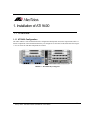
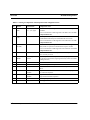
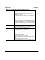
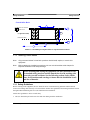
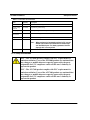
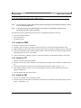
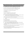
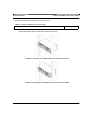
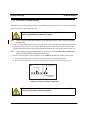
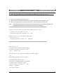
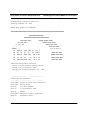
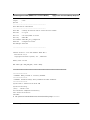
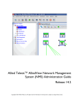
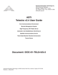
9400 iMAP Installation Guide
Release 8.0 (and up unless reissued)
Issue 1
© 2006 ATI Networks. All rights reserved. Information subject to change without notice.
Introduction
Congratulations on your purchase of a ATI™ 9400, integrated Multiservice Access Platform (iMAP)
product. This product is part of a family of products that leverages Ethernet switching technology to offer
service providers a range of services, including video over xDSL.
Who Should Read This Guide?
This document provides an outline for installation and turn up of the ATI 9400 product, from the unpacking
of materials to setting up the initial user interface. The product is then ready to be introduced to the network.
About this Guide
This guide includes
•
Section 1 provides step-by-step instructions for installing the ATI 9400 system, from unpacking the
chassis to monitoring initialization form the local (CONSOLE) interface.
•
Section 2 lists all components and their specifications.
•
The Appendix gives a list of Glossary Terms as well as a worksheet for office records.
Reason for Update
Added a note on 10G configuration.
© 2003, 2004 Allied Telesyn Networks. All rights reserved. Information subject to change without notice.
Table of Contents
1 Installation of ATI 9400 - - - - - - - - - - - - - - - - - - - - - - - - - -1-1
1.1 Overview - - - - - - - - - - - - - - - - - - - - - - - - - - - - - - - - - - - - - - - - - - - - - - - - - - - - - - - - 1-1
1.1.1 ATI 9400 Configuration - - - - - - - - - - - - - - - - - - - - - - - - - - - - - - - - - - - - - - - - - 1-1
1.2 Selecting a Site - - - - - - - - - - - - - - - - - - - - - - - - - - - - - - - - - - - - - - - - - - - - - - - - - - - - 1-3
1.2.1 Environment - - - - - - - - - - - - - - - - - - - - - - - - - - - - - - - - - - - - - - - - - - - - - - - - - 1-3
1.3 Safety overview - - - - - - - - - - - - - - - - - - - - - - - - - - - - - - - - - - - - - - - - - - - - - - - - - - - 1-5
1.3.1 Safety Guidelines - - - - - - - - - - - - - - - - - - - - - - - - - - - - - - - - - - - - - - - - - - - - - - 1-5
1.3.2 Safety Precautions While Working with Electricity - - - - - - - - - - - - - - - - - - - - - - - 1-6
1.4 Mounting Procedure- - - - - - - - - - - - - - - - - - - - - - - - - - - - - - - - - - - - - - - - - - - - - - - - 1-7
1.4.1 ESD and Antistatic procedures - - - - - - - - - - - - - - - - - - - - - - - - - - - - - - - - - - - - - 1-7
1.5 ATI 9400 Installation - - - - - - - - - - - - - - - - - - - - - - - - - - - - - - - - - - - - - - - - - - - - - - - 1-7
1.5.1 Setup Checklist - - - - - - - - - - - - - - - - - - - - - - - - - - - - - - - - - - - - - - - - - - - - - - - 1-7
1.5.2 Setup Precautions - - - - - - - - - - - - - - - - - - - - - - - - - - - - - - - - - - - - - - - - - - - - - - 1-8
1.6 Install Cards into Chassis - - - - - - - - - - - - - - - - - - - - - - - - - - - - - - - - - - - - - - - - - - - 1.6.1 Install the PEM7 - - - - - - - - - - - - - - - - - - - - - - - - - - - - - - - - - - - - - - - - - - - - - 1.6.2 Install the FC7 - - - - - - - - - - - - - - - - - - - - - - - - - - - - - - - - - - - - - - - - - - - - - - - 1.6.3 Install the FM7 - - - - - - - - - - - - - - - - - - - - - - - - - - - - - - - - - - - - - - - - - - - - - - -
1-9
1-9
1-9
1-9
1.7 Install the ATI 9400 Chassis into the Rack - - - - - - - - - - - - - - - - - - - - - - - - - - - - - - - 1-12
1.7.1 Ensure all Components for Desired Configuration Present - - - - - - - - - - - - - - - - - 1-12
1.7.2 Install the Chassis- - - - - - - - - - - - - - - - - - - - - - - - - - - - - - - - - - - - - - - - - - - - - 1-12
1.8 Connect Grounding - - - - - - - - - - - - - - - - - - - - - - - - - - - - - - - - - - - - - - - - - - - - - - - 1-14
1.9 Connect Power. - - - - - - - - - - - - - - - - - - - - - - - - - - - - - - - - - - - - - - - - - - - - - - - - - - 1-16
1.10 Connect Alarm Cables (Optional) - - - - - - - - - - - - - - - - - - - - - - - - - - - - - - - - - - - - 1-17
1.11 Apply and Check Power - - - - - - - - - - - - - - - - - - - - - - - - - - - - - - - - - - - - - - - - - - - 1-18
1.12 Install the Control Module - - - - - - - - - - - - - - - - - - - - - - - - - - - - - - - - - - - - - - - - - 1-18
1.13 Install the Service Module - - - - - - - - - - - - - - - - - - - - - - - - - - - - - - - - - - - - - - - - - - 1-20
1.14 Install the Network Module- - - - - - - - - - - - - - - - - - - - - - - - - - - - - - - - - - - - - - - - - 1-20
1.15 Install the SFP Module - - - - - - - - - - - - - - - - - - - - - - - - - - - - - - - - - - - - - - - - - - - - 1-21
1.16 Install Filler Plates - - - - - - - - - - - - - - - - - - - - - - - - - - - - - - - - - - - - - - - - - - - - - - - 1-21
1.16.1 Installing the FPF - - - - - - - - - - - - - - - - - - - - - - - - - - - - - - - - - - - - - - - - - - - - 1-21
1.16.2 Installing the FPH- - - - - - - - - - - - - - - - - - - - - - - - - - - - - - - - - - - - - - - - - - - - 1-21
Telesyn User Guide (Table of Contents)
1.17 Configure Local Terminal or PC- - - - - - - - - - - - - - - - - - - - - - - - - - - - - - - - - - - - - - 1-23
1.18 Connect System Cables - - - - - - - - - - - - - - - - - - - - - - - - - - - - - - - - - - - - - - - - - - - - 1-24
1.18.1 Service Module - - - - - - - - - - - - - - - - - - - - - - - - - - - - - - - - - - - - - - - - - - - - - - 1-24
1.18.2 Network Module - - - - - - - - - - - - - - - - - - - - - - - - - - - - - - - - - - - - - - - - - - - - - 1-25
1.18.3 Data Management Cable (MGMT Port on Control Module) - - - - - - - - - - - - - - - - 1-26
1.19 Apply Power and Check Startup Sequence - - - - - - - - - - - - - - - - - - - - - - - - - - - - - - 1-27
1.20 Check the Configuration - - - - - - - - - - - - - - - - - - - - - - - - - - - - - - - - - - - - - - - - - - - 1-30
1.20.1 Check software load- - - - - - - - - - - - - - - - - - - - - - - - - - - - - - - - - - - - - - - - - - - 1-30
1.20.2 Check management interfaces - - - - - - - - - - - - - - - - - - - - - - - - - - - - - - - - - - - - 1-31
1.21 ATI Contact Information - - - - - - - - - - - - - - - - - - - - - - - - - - - - - - - - - - - - - - - - - - - 1-31
3 Appendix - - - - - - - - - - - - - - - - - - - - - - - - - - - - - - - - - - - 3-1
3.1 Glossary of Terms - - - - - - - - - - - - - - - - - - - - - - - - - - - - - - - - - - - - - - - - - - - - - - - - - -3-1
3.2 Telesyn x400 Inventory Form - - - - - - - - - - - - - - - - - - - - - - - - - - - - - - - - - - - - - - - - - -3-2
TOC-2
Telesyn User Guide (Table of Contents)
1. Installation of ATI 9400
1.1 Overview
1.1.1 ATI 9400 Configuration
The ATI™ 9400 is a rack-mounted shelf with a configuration that depends on customer requirements. Table 1-1
lists the components of the ATI 9400 and how they are configured. Use the letters in this table and refer to Figure
1-2 to see where the ATI 9400 components are located.
TN-100-A
ADSL
16
PULL FAULT INSERV
FIGURE 1-1
TN-100-A
ATI 9400 Fully Configured
Telesyn x400 - Installation Guide (Installation of ATI 9400)
1-1
Overview
ATI 9400 Configuration
.
TABLE 1-1
Listing of components with slot/position and configuration notes
No.
Module
Slot/Position
Configuration Notes
A
Service Module
(SM)
6, 8, 10 (left)
At least one is always configured. Unused slots must be configured
with FPFs.
5, 7, 9,11 (right)
Note: For information on SMs supported on the 9400 refer to the ATI
Component Reference.
B
Control Module
(CM)
2, 4 (double)
One card per shelf (occupies two slots).
Includes RS232 and OAM port. ETH0 and ETH1 are not used.
Note: For information on CMs supported on the 9400 refer to the ATI
Component Reference.
C
Network Module (NM)
Slot 0 and Slot 1
At least one is always configured. A Small Form Factor Pluggable
(SFP) module is required. An unused half-slot requires an FPH.
Note: For information on NMs supported on the 9400 refer to the ATI
Component Reference.
D
Fan Controller
3 (half-slot)
Fan Controller. Includes ALM IN port and ALM OUT port. COMM
port is currently not used.
E
Power Entry
Module
Lower right of
chassis
Power Entry Module. Includes power feeds (H), signal ground, returns
(I), and A/B circuit breakers. (Signal ground is only used in an Isolated
Bonding Network.)
F
Fan Module
Center of chassis
Fan Module.
G
ESD
NA
MAC
Inside Chassis
Included with chassis. Located on the front of backplane behind slots 8
and 10.
NA
FPF
Panels for Service
Module
Required when a Service Module slot is not used. Ensures proper airflow and EMI compliance.
NA
FPH
Panel for Network
Module
Required when half-slot for Network Module is not used. Ensures
proper airflow and EMI compliance.
H
-
-
Mounting hole group.
I
Ground
Right side
Primary ground connection
1-2
ESD wrist strap connection point.
Telesyn x400 - Installation Guide (Installation of ATI 9400)
Environment
Selecting a Site
Slot Numbers
A
TN-100-A
TN-100-A
ADSL
16
PULL FAULT INSERV
A
B
H
H
C
F
FIGURE 1-2
D
G
E
I
ATI 9400 Fully Configured
1.2 Selecting a Site
Before installing the ATI 9400, prepare the site to ensure the product will operate in the correct environment, all
materials meet specifications, and all installation tasks can be performed.
1.2.1 Environment
The ATI 9400 is installed in a central office environment that is affected by the existing installed equipment and
the specific requirements of the ATI 9400 shelf. Refer to Table 1-2.
TABLE 1-2
Site Requirements for ATI 9400, Office Installation
Type
Description
Access
To be installed in a restricted access location.
Rear Access
None required.
Telesyn x400 - Installation Guide (Installation of ATI 9400)
1-3
Selecting a Site
TABLE 1-2
Environment
Site Requirements for ATI 9400, Office Installation (Continued)
Type
Description
Rack configuration
Placement: None, but follow local cabling setup (from above, below, etc.)
Care should be taken not to compromise the stability of the rack by the
installation of this equipment.
A maximum of 15 shelves can be installed in a 7 ft. rack. This number may
be limited by the extended size of the cable bundle created by the number of
units.
Note: Due to weight limitations and the size of bundled cabling, 15 shelves
can normally be installed in a single 7 ft. telecom rack. If there is a requirement for more than 15 shelves in a single 7 ft. rack, the user should verify
that the floor loading for the rack, after installing additional units, does not
exceed the floor loading standard for the region or country where the 9400 is
being installed. 9400 installations inside the U.S. would follow the Bellcore
floor loading standard of 114.7 lb. per square foot. See the ATI Component
Specification for the NEBS specification.
Power Supply
Connect to a reliable grounded -48VDC source. The branch circuit overcurrent protection must be rated 20 amp maximum, following NEC requirements for permanent office equipment. Safety is UL 60950
Spacing
Refer to Figure 1-3 Central Office Rack and its numbers:
1. Mounting Width Aperture: 19.7 in (500.4mm) min.
2. Aperture between mounting flanges:
- 17.5 in (444.5 mm) min. (center-mounted flange)
- 17.7 in (450 mm) min. (front-mounted flange)
3. Total Shelf Depth: 11.8 (300 mm):
a. Door or cover:.4 in (10 mm) (Front and Back)
b. In front of Reference Plane for equipment (i.e. subracks): 1.5 in (38.1
mm)
c. Behind Reference Plane: 9.5 in (241.3 mm)
4. Rack Pitch (Midpoint to Midpoint of each chassis): 25.6 in (650.2 mm)
1-4
Telesyn x400 - Installation Guide (Installation of ATI 9400)
Safety Guidelines
Safety overview
Central Office Rack
2
space for external
cable access
3a
3c
(Adjacent Frame)
3
Reference Plane
3b
3a
1
4
FIGURE 1-3
ATI 9400 Space Requirements for Open Rack Environment
1.3 Safety overview
Note:
Only personnel trained in local telco practices should install, replace, or service this
equipment.
Note:
Before starting the installation procedures, the user should read the whole chapter for
important information and safety warnings.
Before installing and cabling the equipment, the user should be aware
of standard safety practices and the hazards involved in working with
electricity to avoid accidents. See the following section, Safety Guidelines, for all cautions and warnings to insure that the installation is safe
and free of hazards.
1.3.1 Safety Guidelines
Before working on the equipment, the user should be aware of standard safety guidelines and the hazards
involved in working with electricity to avoid accidents. Follow these guidelines and warnings and those located
throughout this installation guide for a safe and hazard-free installation.
Follow these guidelines to insure overall safety:
• The user should keep all work areas clear and clean during and after installation.
Telesyn x400 - Installation Guide (Installation of ATI 9400)
1-5
Safety overview
•
•
•
•
Safety Precautions While Working with Electricity
The user should keep all tools away from walk areas where personnel could trip over them.
The user should not wear loose clothing that could catch on equipment. Secure any loose clothing.
The user should wear safety glasses if working under conditions that might be hazardous to eyes.
The user should not perform any action that creates an unsafe or hazardous situation for themselves or other
personnel.
Note:
Insure proper power installation prior to installing system cards. Improper power installation
can damage the system chassis and cards.
Note:
It is important that the chassis cooling fans operate, within their normal running temperature
range, while the system is powered up.
Insure circuit breakers are OFF before starting the installation process.
1.3.2 Safety Precautions While Working with Electricity
Guidelines when working with electrically powered equipment:
• Locate the Power Off switch for the system being installed or serviced. In the event of an electrical accident, the user can quickly turn the power off.
• Disconnect all power by turning the circuit breakers off before:
• Installing or removing a chassis
• Working near the power supply
• Do not work alone if potential hazards exist.
• Never assume that power is disconnected from a circuit; always check the circuit.
• Inspect the work area carefully for possible hazards, such as moist floors, ungrounded power extension
cables, frayed power cords, and missing safety grounds.
• If an electrical accident occurs, proceed as follows:
• Use caution; do not become a victim yourself.
• Turn off power to the system.
• If possible, send another person to get medical aid. Otherwise, assess the condition of the victim and then
call for help.
• Determine if the person needs rescue breathing or external cardiac compressions; then, take appropriate
action.
1-6
Telesyn x400 - Installation Guide (Installation of ATI 9400)
ESD and Antistatic procedures
Mounting Procedure
1.4 Mounting Procedure
1.4.1 ESD and Antistatic procedures
Proper ESD protection is required when handling equipment. Installation and maintenance personnel should be
properly grounded using ground straps to eliminate the risk of ESD damage to the equipment.
1.
Whenever dealing with electrostatic-sensitive equipment, wear a ground or foot strap.
2.
Ensure customer power source for the product is off.
1.4.1.1 Antistatic procedures:
Verify that the chassis is electrically connected to earth ground.
• Wear an ESD-preventive device such as a foot strap or wrist strap, ensuring that it makes good contact
with the user’s skin. If a foot strap is used, the floor must be ESD conductive.
1.
2.
Connect the clip from the ESD-preventative device to an unpainted surface of the frame, rack or ESD
point on the chassis frame connecting it directly to ground. This ensures that unwanted ESD voltages
safely flow to ground.
3.
Wear the ESD-preventive device correctly to properly guard against ESD damage and shock. If no foot or
wrist strap is available, the user should ground themselves by making contact with an unpainted, metal
part of the chassis.
1.5 ATI 9400 Installation
Installation and power up of the ATI 9400 follows.
1.5.1 Setup Checklist
Table 1-3 lists the items that are to be provided by the customer.
TABLE 1-3
Customer Item Checklist
Item
Quantity
Description
MGMT cable
1
RJ-45, connectorized at one end, Cat 5
Bay Power
Cabling
12 awg, length determined by shelf position and how cabling is routed
Alarm cable
3
RJ-45, connectorized at one end, cat 5
Bolt
6
M6 (Number depends on how shelf mounted)
Telesyn x400 - Installation Guide (Installation of ATI 9400)
1-7
ATI 9400 Installation
TABLE 1-3
Setup Precautions
Customer Item Checklist
Item
Quantity
Description
Voltmeter
1
Used to check the voltage at the terminal block
Double crimp
terminal
as needed
Required for ground wiring.
Crimping Tool
1
Used to put ring terminals on power cabling.
#2 Phillips
screwdriver
1
Used for mounting the chassis
1
Used to connect local PC/terminal for local interface
Ring Terminals
RS232 cable
#6 studs for 12 awg wire
Note:
cable ties
as needed
When using an AC-powered terminal or PC, use an
RS232 line isolation unit between the terminal/pc
and the RS232 port. For battery-powered devices
(laptop) this is not required.
n/a
1.5.2 Setup Precautions
FCC - The ATI 9000 product complies with FCC requirements for
emissions radiation. Users of the ATI 9000 product are cautioned that
any changes or modifications not expressly approved by the party
responsible for FCC compliance could void the user’s authority to
operate the product.
FCC - The ATI 7400 product complies with FCC requirements for
emissions radiation. Users of the ATI 7400 product are cautioned that
any changes or modifications not expressly approved by the party
responsible for FCC compliance could void the user’s authority to
operate the product.
1-8
Telesyn x400 - Installation Guide (Installation of ATI 9400)
Install the PEM7
Install Cards into Chassis
1.6 Install Cards into Chassis
Note:
Do not attempt to install system cards without observing correct antistatic procedures. Failure
to do so may damage cards.
Note:
Insure that all cards are seated properly. A card that is only partially connected to the
backplane may affect system operation.
The following cards are installed into the chassis prior to installing the chassis into the rack:
• Power Entry Module (PEM7)
• Fan Controller (FC7)
• Fan Module (FM7)
1.6.1 Install the PEM7
1.
Take the card from its antistatic container.
2.
If possible, place the chassis vertically on a flat secure surface. This makes inserting the PEM7 easier.
3.
Slide the PEM7 into the bottom-right of the chassis until it lines up with the backplane connector on the right.
4.
Slowly press the PEM7 with the thumbs until the PEM7 is fully inserted into the backplane and the flange is
flush against the screw holes of the chassis.
5.
Using a small head (#1) phillips screwdriver, take the provided screws and attach the PEM7 to the chassis.
1.6.2 Install the FC7
1.
Take the card from its antistatic container.
2.
Hold the card securely (such as holding it in one hand with your fingers on the outside rim), component side
up.
3.
Press the release button on the inside of the latch and push the latch out. (Refer to Figure 1-14.)
4.
While holding the latch/faceplate, slowly but firmly push the card into the slot until the latches begin to
engage the locking rail.
5.
Close the latches until they lock into place.
1.6.3 Install the FM7
1.
Take the fan assembly from its antistatic container.
2.
Press the lock-latch in the middle of the faceplate, and ensure the bottom half of the faceplate drops. (Refer to
Figure 1-4 and Figure 1-5.)
Telesyn x400 - Installation Guide (Installation of ATI 9400)
1-9
Install Cards into Chassis
FIGURE 1-4
FIGURE 1-5
3.
Install the FM7
Front of the FM7 Showing the Lock Latch
FM7 with lock-latch open, partially inserted
Slide the assembly into the center of the shelf until it is flush with the shelf surface, applying firm pressure
until fully seated. See Figure 1-6
1-10
Telesyn x400 - Installation Guide (Installation of ATI 9400)
Install the FM7
Install Cards into Chassis
FIGURE 1-6
4.
FM7 fully inserted with lock-latch open
Pull the lower faceplate up to pull the FM7 all the way into the lock the assembly into place. See Figure 1-7
FIGURE 1-7
FM7 inserted with lock-latch closed
Telesyn x400 - Installation Guide (Installation of ATI 9400)
1-11
Install the ATI 9400 Chassis into the Rack
Ensure all Components for Desired Configuration
1.7 Install the ATI 9400 Chassis into the Rack
1.7.1 Ensure all Components for Desired Configuration Present
Using Table 1-1as a guide, ensure that all components used for the installation are present:
•
•
•
•
•
•
•
ATI 9400 shelf (includes ATI 9400 chassis and FM7, FC7, PEM7, and MAC)
Network Module (at least 1) and SFP for each Network Module
Control Module (1)
Service Module (at least 1 up to 7)
FPF (none to 6, depending on the Service Module configuration)
FPH (none or 1, depending on Network Module configuration)
Cable for each Service Module (length determined by office configuration)
Note:
5.
All of these items can be ordered as required. Refer to your ATI representative for orderable
part numbers. Refer to the Hardware Reference for more information.
Enter into your office records the serial number of the chassis, which will be a S/N label on the rear of the
chassis. (This may be needed if the ATI 9400 requires troubleshooting.)
Note:
A worksheet to place serial numbers for the ATI 9400 is included at the end of this document,
Table 3-2.
1.7.2 Install the Chassis
1.
In an antistatic environment, remove the chassis from its packaging.
2.
Note the flanges, which are attached so that the shelf is center-mounted.
Note:
If the user wishes to front mount the ATI 9400 chassis, contact your ATI representative.
Figure 1-8 and Figure 1-9 show the different mounting options.
3.
Install the bottom mounting bolts in the rack. Tighten until there is a 1/4 inch gap between the bolt flange and
the rack surface.
4.
Pick up the ATI 9400 chassis by placing your hands on the inside of the chassis, palms up, and placing in the
rack, lining up the notch on the bottom of the flange with the bottom mounting bolt.
5.
Once the shelf is mounted, hand tighten the bottom bolts.
6.
Install the remaining mounting bolts. Use a minimum of three bolts for each side, with the other two bolts
used being one of the middle mounting groups and one at the top. Refer to Figure 1-9.
7.
Verify the FM7 is installed in the chassis.
1-12
Telesyn x400 - Installation Guide (Installation of ATI 9400)
Install the Chassis
8.
Install the ATI 9400 Chassis into the Rack
Install and hand-tighten the flange bolts to secure the shelf.
TABLE 1-4
Chassis retaining screw torque setting
Torque setting for M6 chassis retaining screws
Note:
35.0 in lb. MAX
An alternative to this procedure (Step 2 forwards) is to have one person hold the chassis in
place while another person inserts the bolts into the chassis.
FIGURE 1-8
FIGURE 1-9
Mounting the ATI 9400 Chassis into a Rack Front Mount
Mounting the ATI 9400 Chassis into a Rack Center Mount
Telesyn x400 - Installation Guide (Installation of ATI 9400)
1-13
Connect Grounding
Install the Chassis
1.8 Connect Grounding
The primary ground for the ATI 9400 shelf is a grounding stud located on the right side of the chassis mounting
block (it will have the grounding symbol
).
The separate protective earthing terminal provided on this product
shall be permanently connected to earth.
Note:
1.
Using a 12 awg grounding cable (green with yellow stripe), connect the chassis grounding stud to office primary ground using two nuts or a lock washer and a nut (for two secured points). Connect the wire to the
grounding stud using a double crimp terminal (PANDUIT PMNF6-4R or equivalent). Refer to Figure 1-11
Note:
2.
There is only one grounding procedure, since the Logic Ground is done using the supplied
bonding strap.
Torque setting for the grounding stud nut is 22.0 in. lb. (2.5 N*m) MAX. When tightening the
outer nut, ensure that the inner nut is held securely.
Since the signal and primary office grounds are to be combined, installation is complete, which means:
1.
Leave the bonding strap connected to the center terminal of the terminal block in place.
2.
Do not connect anything else to the center terminal of the terminal block. Refer to Figure 1-10.
Connection to primary
grounding post
PEM7
Metal strap
-48A -48B LGND RETA RETB
Primary grounding post
on chassis
FIGURE 1-10
Single Grounding Configuration
The metal strap must be securely tightened using the two supplied
screws for the unit to function properly.
1-14
Telesyn x400 - Installation Guide (Installation of ATI 9400)
Connect Grounding
nu
wat
cri she
m r
wa ped
s c
nu her onn
ec
t
tor
Gr
ou
nd
ing
ch stu
as f
sis
Install the Chassis
Grounding stud
exploded side view
Grounding Stud
FIGURE 1-11
Primary grounding post exploded view
Telesyn x400 - Installation Guide (Installation of ATI 9400)
1-15
Connect Power.
Install the Chassis
1.9 Connect Power.
Before connecting any power (or grounding) cable, ensure the following:
1. Connect to a reliably grounded 48VDC SELV (Safety Extra Low
Voltage) source. (SELV - UL60950 - A circuit designed so that its
voltages do not exceed a normal and fault value of 42.4 Vpeak or 60
VDC.
2. The branch circuit overcurrent protection must be rated 20A
3. A readily accessible disconnect device that is suitably approved and
rated shall be incorporated in the field wiring
4. The customer-provided power (-48 VDC) is off (visibly disconnected) and the ATI 9400 shelf circuit breakers are off (0).
5. Use 12 AWG copper conductors.
1.
Remove the plastic cover for the power and grounding terminals.
2.
Connect the -48VDC power feeds and DC returns for A and B.
Note:
The shelf can operate on one power feed (A or B). The customer can select to connect the A
and B feeds to different customer power sources, so that if one power source goes down, the
shelf can continue to operate.
If the customer utilizes a single power source, a Major alarm will be
raised in the 9400 system. To clear the alarm, jumper the 48A and 48B
feeds together as illustrated in Figure 1-12
As noted above, the customer has the option of connecting to a single power source. The wiring configuration
for this option is detailed in the figure below. Note the dashed jumper connecting A and B power feeds.
1-16
Telesyn x400 - Installation Guide (Installation of ATI 9400)
Install the Chassis
Connect Alarm Cables (Optional)
Jumper -48A
to -48B
FIGURE 1-12
Jumper RETA
to RETB
Single Power Source jumpers
1.10 Connect Alarm Cables (Optional)
Note:
Connecting the alarm cables at this time is optional. After initial system installation is complete,
the user can return to this section and connect the alarm cables and configure the system
alarms.
Two RJ-45 plugs are used as connecting cables for external alarms. Connect them as follows:
• one RJ-45 used for alarm indicator input, into the ALM IN port
• one RJ-45 used for the ALM OUT port as required.
Refer to the ATI User Guide for more information.
Telesyn x400 - Installation Guide (Installation of ATI 9400)
1-17
Apply and Check Power
Install the Chassis
1.11 Apply and Check Power
1.
Ensure the customer power supply is OFF.
2.
Ensure that the ATI 9400 shelf circuit breakers are OFF (0).
3.
Turn the customer power supply ON. Power is now being applied to the terminal block but not to the shelf
components.
4.
With the power/grounding plastic cover still removed, check for voltage at the terminal block using a voltmeter. With the shelf operating a nominal voltage of -48VDC, the reading should be between -40 to -57.6 VDC.
If the voltage is outside this range, check the customer-supplied power.
5.
Put the plastic cover back on.
6.
Turn the ATI 9400 circuit breakers ON (-).
7.
The fans will start to operate.
Note:
If the fans do not operate, ensure the FM7 is installed as part of the chassis. If the FM7 is
installed, contact your ATI representative.
The 9400 shelf fans will start operation at a very high speed. Fan speed is self-regulating and will automatically
adjust as necessary. After a short period of time, fan speed will automatically reduce. Insure that the fans start
when the 9400 shelf circuit breakers are turned ON(-) and that they reduce speed within a few minutes.
Note:
If the fans do not reduce speed after a few minutes, turn the 9400 shelf circuit breakers OFF (0)
and contact your ATI representative.
8.
Turn the shelf circuit breakers OFF (0).
9.
The shelf is now ready for the remainder of the cards to be inserted
1.12 Install the Control Module
Note:
Do not attempt to install system cards without observing correct antistatic procedures. Failure
to do so may damage cards.
1.
Take the card from its antistatic container. (Set aside the Special Instructions for Ferrite instructions and
the ferrite for the Ethernet cable. Refer to Section 1.18.3.)
2.
Hold the card securely with the lock-latch and label on the inside of the chassis as illustrated in Figure 1-13.
Note:
1-18
This example is for the CFC24, but it can be applied to any CM supported by the 9400
system.
Telesyn x400 - Installation Guide (Installation of ATI 9400)
Install the Chassis
Install the Control Module
PULL
CFC
24
FAULT
TN-400-A
ACT
AJOR
CRIT
INOR
SWACT
ACO'LT
INSRV
MGMT
CONSOLE
FIGURE 1-13
TN-400-A
CFC24 Faceplate
3.
Press the release button on the inside of the latches and push the latches out. (Refer to Figure 1-14.)
4.
Locate the double slot (2 and 4) where the card is to be inserted.
5.
While holding the latches/faceplate, slowly with a firm pressure push the card into the double slot until the
latches begin to engage the locking rail.
Note:
6.
A firm pressure is required to seat the card. The lock-latch does not assist in seating the card.
Close the latches until they lock into place.
FIGURE 1-14
Latch in the Out Position (Release Button has been Engaged)
FIGURE 1-15
Detail of the lock-latch in locked and then opened position
Telesyn x400 - Installation Guide (Installation of ATI 9400)
1-19
Install the Service Module
Install the Chassis
1.13 Install the Service Module
Note:
This example is for the FE10, but it can be applied to any SM supported by the 9400 system.
The Service Modules can be placed in any of the following slots: 6, 8, 10 (left), and 5, 7, 9, 11 (right). It is recommended that the slots be filled in numerical order slot 5-11.
1.
Take the card from its antistatic container.
2.
For insertion into slots 6, 8, or 10, hold the card securely with component side down. For insertion into slots
5, 7, 9, or 11, hold the card by its latches with component side up. (For any slot, the latch/label will go on the
inside of the chassis). Refer to Figure 1-16.
TN-100-A
FE10
PULL FAULT
TN-100-A
INSERV
Slot Numbers
FIGURE 1-16
For 9400 SM Cards, Latch Label on Inside of Chassis
3.
Press the release buttons on the inside of the latches and push the latches out. (Refer to Figure 1-14.)
4.
While holding the card, slowly but firmly push the card into the slot until the latches begin to engage the
locking rail.
5.
Close the latches until the card locks into place.
1.14 Install the Network Module
Note:
This procedure can be applied to any NM supported on the 9400.
The Network Module(s) go into Slots 0 and 1. It is recommended that Slot 0 be filled first.
1.
Take the card from its antistatic container.
2.
Hold the card securely with component side down (lock-latch and label on the inside of the chassis)
3.
Locate the half-slot where the card is to be inserted.
4.
Press the release button on the inside of the latch and push the latch out. (Refer to Figure 1-14.)
5.
While holding the card, slowly but firmly push the card into the slot until the latch begins to engage the locking rail.
1-20
Telesyn x400 - Installation Guide (Installation of ATI 9400)
Installing the FPF
6.
Install the SFP Module
Close the latch until the card locks into place.
1.15 Install the SFP Module
The Small Form Factor Pluggable modules (LX or SX), which are inserted in the NM cards, can be ordered from
your ATI representative. The 850 model usually has a latch on the top that locks into place when it is fully seated.
(This latch is pushed in to eject the SFP.)
1.16 Install Filler Plates
The FPF and FPH are needed to keep dust from entering the chassis
and to ensure proper airflow. The shelf may overheat or become damaged if these are not properly installed in every unused slot.
Do not allow the metal plate to touch the components of neighboring
cards.
While inserting the FPF and FPH, be careful not to get fingers pinched
between cards.
1.16.1 Installing the FPF
For the ATI 9400, FPF are installed in empty service module slots. To install the FPF:
1.
Hold the FPF card securely and slowly but firmly push the card into the slot until the latches begin to engage
the locking rail.
2.
Close the latches until the card locks into place.
TABLE 1-5
9400 system configuration and installation of filler plate full (FPF)
System Configuration
Service Module Location
Location of filler plates
9400 system
6, 8, 10 (left) and 5, 7, 9,11 (right)
Empty Service Module slots
1.16.2 Installing the FPH
For the ATI 9400, FPF are installed in empty service module slots. To install the FPH:
Telesyn x400 - Installation Guide (Installation of ATI 9400)
1-21
Install Filler Plates
Installing the FPH
1.
Hold the FPH card securely and slowly but firmly push the card into the slot until the latch begins to engage
the locking rail
2.
Close the latch until the card locks into place.
The placement of filler plates is dependent upon the configuration of the 9400 system. The following table illustrates the differences between the two configurations.
TABLE 1-6
Single or dual network module configuration and installation of filler plate half (FPH)
System Configuration
Network Module Location
Location of filler plate
One network module
Half slot 0 (recommended)
Half slot 1
Two network modules
Half slot 0 and 1
None
1-22
Telesyn x400 - Installation Guide (Installation of ATI 9400)
Installing the FPH
Configure Local Terminal or PC
1.17 Configure Local Terminal or PC
The RS-232 (CONSOLE) terminal port is used during the initial installation startup to connect the ATI 9400 to a
local management device, which can be:
• A terminal (VT-100 compatible)
• A PC with terminal emulation software
The CONSOLE port is a DB9 female socket configured as a DCE, which allows for the direct connection to the
terminal or PC. Refer to 2.9.1 for a listing of DB9 pin assignments.
The settings for the CONSOLE port are initially configured with the following default values
Note:
When using the CONSOLE port, ensure that the terminal emulation software has FLOW
CONTROL disabled.:
TABLE 1-7
Default Asynchronous Port Settings
Option
Default
Option
Default
ATTENTION
BREAK
MAXOQLEN
0 (Unrestricted)
CDCONTROL
IGNORE
MTU
1500
DATABITS
8
NAME
ASYN 0
DEFAULTSERVICE
FALSE
OUTFLOW
HARDWARE
DTRCONTROL
ON
PAGE
22
ECHO
ON
PARITY
NONE
FLOW
HARDWARE
PROMPT
DEFAULT (CMD>)
HISTORY
30
SECURE
ON
INFLOW
HARDWARE
SERVICE
NONE
IPADDRESS
NONE
SPEED
9600
IPXNETWORK
NONE
STOPBITS
1
LOGIN
ON
TYPE
VT100
When using an AC-powered terminal or PC, use an RS232 line isolation unit between the terminal/pc and the RS232 port. For batterypowered devices (laptop) this is not required.
1.
Connect the RS-232 cable from the terminal or PC to the ATI 9400 TERM port.
2.
If the device is a PC, bring up the terminal emulation window.
Telesyn x400 - Installation Guide (Installation of ATI 9400)
1-23
Connect System Cables
Service Module
1.18 Connect System Cables
1.18.1 Service Module
1.18.1.1 SMs with RJ45 connectors
Attach the RJ45 end of the Ethernet cable to the specified port on the FE10 card.
FIGURE 1-17
FIGURE 1-18
Note:
1-24
FE10 Cable Connector
FE10 data cable connectors
Each RJ45 cable connected to the FE10 card should be dressed neatly and tightly. Do
not permit cables to loop.
Telesyn x400 - Installation Guide (Installation of ATI 9400)
Network Module
Connect System Cables
FIGURE 1-19
FE10 RJ45 Connector Dressing
1.18.1.2 SMs with RJ21 connectors
Attach the connectorized end of the cable to the SM card.
1.
Use the screw and a tie wrap to secure in place.
2.
Split off voice and data service using DC non-blocking splitters
Note:
Splitters are not required when using ADSL8S cards.
Note:
Do not over tighten the screw. Hand tighten to secure. Then install the tie wrap, pulling it snug
enough to secure the connector.
FIGURE 1-20
RJ21 cable connector at the SM card
1.18.2 Network Module
1.
Attach the optical cables to the NM card.
2.
Attach the other end of the optical cables to the uplink device.
Telesyn x400 - Installation Guide (Installation of ATI 9400)
1-25
Connect System Cables
Data Management Cable (MGMT Port on Control
1.18.3 Data Management Cable (MGMT Port on Control Module)
Note:
Connect this cable only if the user plans to use the MGMT port for the management interface.
Refer to the ATI User Guide.
Follow the instructions included with the Control Module for placing the ferrite on the ethernet cable.
Connect one end of the ethernet cable to the MGMT port and connect the other end to a port that connects to the
TCP/IP network, as described in the ATI User Guide.
1-26
Telesyn x400 - Installation Guide (Installation of ATI 9400)
Data Management Cable (MGMT Port on Control Module)
Apply Power and Check Startup Sequence
1.19 Apply Power and Check Startup Sequence
1.
Turn the A and then B circuit breakers on (-).
2.
Observe that the fans should start and airflow should be begin horizontally through the unit.
3.
Observe the startup sequence on the terminal interface, which should show the following:
Note:
The startup sequence the user observes on the terminal may not exactly match the one
illustrated below. However, it should be free of any error messages.
@@@@@@@@@@@@@@@@@@@@@@@@@@@@@@@@@@@@@@@@@@@@@@@@@@@@@@@@@@@@@@@@@@@@@@@@@@@
Telesyn 6G Central Fabric Controller Boot Loader Version 3.0.g.01
Created on Thu 03/11/2004 at 9:07a
Copyright Allied Telesyn Networks, Inc., 2003
VxWorks Version 5.5 for IBM PowerPC 405GP Rev E
BSP version 1.2/2
Copyright Wind River Systems, Inc., 1984-2002
@@@@@@@@@@@@@@@@@@@@@@@@@@@@@@@@@@@@@@@@@@@@@@@@@@@@@@@@@@@@@@@@@@@@@@@@@@@
FPGA Version 1.4
Starting Telesyn Product Software Loading.
Attaching to Flash File System ... done.
/tffs/
- Volume is OK
Press any key to stop automatic loading of software image...
1 0
Automatically loading software image...
Loading from boot device 'emac'...
Active CFC or DebugIP enabled: MUX Enabled
Attached TCP/IP interface to emac0.
Attaching network interface lo0... done.
Loading... 21061184
Starting at 0x10000...
Telesyn x400 - Installation Guide (Installation of ATI 9400)
1-27
Apply Power and Check Startup Sequence
Data Management Cable (MGMT Port on Control
Attached TCP/IP interface to emac unit 0
Attaching interface lo0...done
Adding 44551 symbols for standalone.
@@@@@@@@@@@@@@@@@@@@@@@@@@@@@@@@@@@@@@@@@@@@@@@@@@@@@@@@@@@@@@@@@@@@@@@@@@@
,@@@@@@@@@@@@@@@@@@@@,
,@@@@@@@@@@@@@@@@@@@@@@@@@@@@@@@@@@@,
,@@@@ @@@@ @@@@""
""@@@@@@ @@@@@@ @@@@@,
,@@" @@@",@@@""
""@@@@@ @@@@@ @@@@@,
,@" ,@@" ,@@"
/"
/"
@@@@@@
/
"@@@@@ @@@@ @@@@,
/"
"@@@@ @@@@ @@@@
/"
@""@ @""@ @""@
@@
@@@@ @@
@@@@
@@
@@
@@
@@
@@@@ @@
@@@@
@@
@@
@@
@@
@@@@ @@@@ @@@@ "@@@
@@
@@
@@@, @@
@@
@@@
,
@ @@
" @@
@@@
@@
@
@ @@@ @
@@@@ @@@@ @@@@
@ @@@
@@@@@@.@@@@.@@@@
@@
@
@@
@@@@@@.@@@@.@@@@
@@
@
@@
@@@@ @@@@ @@@@
Telesyn 6G Central Fabric Controller
Version 4.0.0.BETA.20040716 (Lab-Only Build)
Created on Fri 07/16/2004 at 4:10a
Copyright Allied Telesyn Networks, Inc., 2004
---------------------------------------------Software Version Information
---------------------------------------------Build name : Telesyn 6G Central Fabric Controller
Build type : Lab-Only Build
Revision
: 4.0.0.BETA.20040716
Built on
: Fri 07/16/2004 at 4:10a
Built by
: ccadmin
Environment: ccbuild_R4.0_nightly_integration
Baseline
1-28
: Integration Latest
Telesyn x400 - Installation Guide (Installation of ATI 9400)
Data Management Cable (MGMT Port on Control Module)
Target
: cfc6
Options
:
Apply Power and Check Startup Sequence
---------------------------------------------Boot ROM Version Information
---------------------------------------------Boot ROM
: Telesyn 6G Central Fabric Controller Boot Loader
Revision
: 3.0.g.01
Built on
: Thu 03/11/2004 at 9:07a
Built by
: mbuilder
Environment: mbuilder_R3.0_integration
Baseline
: Integration Latest
BuildTarget: bootcfc6
----------------------------------------------
VxWorks Version 5.5 for IBM PowerPC 405GP Rev E
BSP version 1.2/2
Copyright Wind River Systems, Inc., 1984-2002
Memory Size: 127 MB
WDB Comm Type: WDB_COMM_END, State: Ready
@@@@@@@@@@@@@@@@@@@@@@@@@@@@@@@@@@@@@@@@@@@@@@@@@@@@@@@@@@@@@@@@@@@@@@@@@@@
********************
* WARNING: Debug IP mode is currently enabled.
********************
* WARNING: Standard Telesyn boot procedure has been disabled.
********************
System Time is 2004-07-16 09:28:45.188
System initializing...
/tffs/
- Volume is OK
Initialization completed successfully
User Access Verification
Username:
4.
The system will run initialization tests and end with the prompt Username:
Telesyn x400 - Installation Guide (Installation of ATI 9400)
1-29
Check the Configuration
5.
Input a user ID of officer and a password of officer.
6.
Check the management logs for any problems by inputting the following:
Check software load
> SHOW LOG SEVERITY=CRITICAL
> SHOW LOG SEVERITY=MAJOR
> SHOW LOG SEVERITY=MINOR
7.
Check for any alarm conditions by inputting the following:
> SHOW ALARMS ALL
8.
Determine if there are any faults as a result of performing Steps 6 and 7.
• If any logs are produced, or if an alarm has a status other than INFO, contact your ATI representative and
review the output.
Note:
If the MAC card is bad, the following is produced:
- A SYS009 log is generated with text “Can Not Read MAC Address”
- A major alarm is set against the shelf with the text “Can Not Read MAC Address”
• If there are no faults, go to section Check the Configuration.
1.20 Check the Configuration
1.20.1 Check software load
1.20.1.1 ATI 7400
Although control modules and service modules are shipped with release files already present in FLASH memory, the release file should be compared with the latest software release files that are available from ATI or if this
is a replacement card, the current system loads. See section 1.21 for contact information.
Once a software release file is downloaded onto a network server, copy it to the Control Module FLASH file system, load it into FLASH memory, make it the active load, and ensure that when the Control Module reboots this
latest load is always used. If this is a replacement card, make sure that the current system load is loaded into the
card. Also ensure the service module loads are obtained from the control module.
Details on the steps to do this are in section, File Management and Software Release Upgrade of the ATI
User Guide.
1.20.1.2 ATI 9400
The CFC24 in the 9400 comes equipped with optional Compact FLASH (CFLASH). Compact Flash (CFLASH)
is a removable memory card that will insert into the faceplate of CFC24 Control Module. This extra memory can
be used to store release load files, databases, and captured log files. Compact FLASH is a small portable card
1-30
Telesyn x400 - Installation Guide (Installation of ATI 9400)
Check management interfaces
ATI Contact Information
that the user inserts into the CFC24 similar to FLASH on a digital camera or other device. See Section 8 of the
ATI User Guide for more information on CFLASH.
Refer to the ATI Component Specification for information on 9400 hardware and software compatibilities.
1.20.2 Check management interfaces
The ATI 9400 is now connected to a local terminal over an RS232 cable and can be queried. Refer to the ATI
User Guide, which shows how to query the initial ATI 9400 status.
The ATI User Guide can then be used to configure the management interfaces.
For more information on system hardware refer to the ATI Component Reference.
1.21 ATI Contact Information
If assistance or information is required in the installation of this equipment, contact ATI Technical Support or
your ATI Representative.
Telesyn x400 - Installation Guide (Installation of ATI 9400)
1-31
ATI Contact Information
1-32
Telesyn x400 - Installation Guide (Installation of ATI 9400)
Check management interfaces
3. Appendix
3.1 Glossary of Terms
TABLE 3-1
Glossary of Terms
Acronym
Meaning
ADSL
Service module. ADSL8S, ADSL16, ADSL16B, SHDSL16, and ADSL24. Annex-A or Annex-B
with 8, 16, or 24 ports.
CFC24
Control Module. Controller with 24G Bandwidth
CM
Control Module. Names of cards use <description><number of ports> naming
FC7
Fan Controller
FE10
Service module. Fast Ethernet (10/100) service with 10 ports
FM7
Fan Module
FPF
Filler Panel Full. Occupies a full slot
FPH
Filler Panel Half. Occupies a half slot
FX10
Service module. Fiber-based service with 10 ports
GE3
Network Module. Gigabit Ethernet service 3 port
MAC
Media Access Controller. Number that uniquely identifies a network component
NM
Network Module
PEM7
Power Entry Module
POTS24
24-port POTS service for analog lines.
SM
Service Module. Names of cards use <description><number of ports> naming
Telesyn x400 Series - User Guide (Appendix)
3-1
Telesyn x400 Inventory Form
3.2 Telesyn x400 Inventory Form
You can use the following form to record registration information about the Telesyn x400 and keep with your
office records.
Note:
You may also identify the product with CLI commands. Refer to the Telesyn User Guide.
TABLE 3-2
No.
Registration Information for the Telesyn x400
Location
Serial Number
1
2
3
4
5
6
7
8
9
10
11
12
13
14
15
16
17
18
19
20
3-2
Telesyn x400 Series - User Guide (Appendix)
Notes