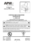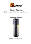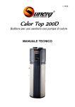
1
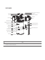
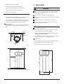
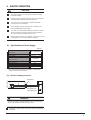
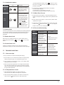
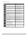
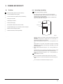
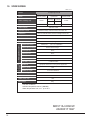
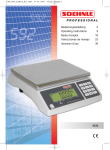
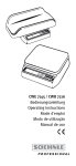
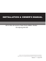
INSTALLATION & OWNER’S MANUAL
All In One Air-source Heat Pump Water Heater
EcoSpring ES190
Thank you very much for purchasing an EcoSpring ES190 Heat pump water heater.
Before using your unit , please read this manual carefully and keep it for future reference.
Verson 1.1 July.2012
WARNING
This unit requires reliable earthing
before usage to prevent potential
injury or death
Please ask a qualified service technician
for a reliable earthing connection
Your safety is the most important!
PARTS NAMES
Power Connect Box and cover
Top Cover
Compressor
Electronic Control Box
Fan Unit
Front Cover
Rear Cover
Display
Evaporator Filter
Magnesium Stick Cover
Front Decorative Board
Magnesium Stick
Temperature Sensor T5
TPR Valve
Water Outlet
Water Inlet
Electric Element Cover
Thermostat TCO
Thermostat TOD
Electric Heater
Drain port
NOTE
All pictures in this manual are for explanation purposes only. They may be slightly different from the heat pump water heater you
purchased. The actual unit shall prevail.
CONTENTS
PAGE
PRECAUTIONS...................................................................................... 1
ACCESSORIES...................................................................................... 2
INSTALLATION LOCATION..................................................................... 2
INSTALLATION ..................................................................................... 3
PIPELINE CONNECTION ....................................................................... 4
ELECTRIC CONNECTION....................................................................... 5
OPERATING INSTRUCTION................................................................... 7
RUNNING AND CAPABILITY................................................................... 13
MAINTENANCE...................................................................................... 15
SPECIFICATIONS................................................................................... 16
WARNING
Ask a professional installer for installation of the air source
heat pump water heating unit.Improper installation may result
in water leakage, electric shock, or fire.
This appliance shall be installed in accordance to AS/NZS
standards.
This appliance should not be used by children.
Repairs and maintenance must only be undertaken by a
professionalservice technician.
Improper repair and maintenance may result in water leakage,
electric shock or fire.
In order to avoid electric shock, fire or injury, if any abnormality is detected, such as smell of smoke, turn off the power
supply and contact your service agent for instructions.
Never use wire or fuse with the incorrect current loading. Use
of wrong wire or fuse may cause the unit to break down or a
ignite.
Do not insert fingers, rods or other objects into the air inlet or
outlet. When the fan is rotating at high speed, it will cause
injury.
Never use flammable spray such as hair spray or lacquer
paint near the unit. It may cause a fire.
1. PRECAUTIONS
To prevent injury to the user, other people and/or property damage,
the following instructions must be adhered to. Incorrect operation
may cause harm or damage.
The safety precautions listed here are divided into two categories.
In either case, important safety instructions are listed to which
close attention must be paid.
WARNING
Failure to observe a warning may result in death or serious
injury.
CAUTION
Failure to observe a caution may result in injury or
equipment damage.
Never touch the air outlet or the horizontal blades while the
swing flap is in operation. Fingers may be caught or the unit
may break down.
Never put any objects into the air inlet or outlet. Objects
touching the fan at high speed can be dangerous.
If the supply cord is damaged, it must be replaced by the
manufacturer or your installer or an electrician in order to
avoid damage to the unit.
An all-pole disconnection device which has at least 3mm
separation distance in all pole and a Residual Current Device
(RCD) with a rating of above 10mA shall be incorporated in
the fixed wiring according to the AS/NZS standards.
DISPOSAL: Do not dispose electrical appliances as unsorted
municipal waste, use separate collection facilities.
Contact you local government for information regarding the
collection systems available.
If electrical appliances are disposed of in landfills or dumps,
hazardous substances can leak into the groundwater and get
into the food chain, damaging your health and well-being.
WARNING
The water heating unit must be earthed effectively.
A creepage breaker must be installed near the power supply.
For the purpose of warning and reminding, do not remove the
labels from the unit.
Installation & Owner‘s Manual
1
CAUTION
The earth pole of terminal must be earthed,and the rated
current should be more than 20A. Make sure that power
supply terminal and power supply plug are dry and have a
good connection.
Method: Turn on power supply, run the unit for 30 minutes
then turn it off and check whether the power supply plug is
hot. If it is hot (more than 50℃), it needs to be replaced to
prevent potential electric shock or fire.
Do not use the air-source water heater for other purposes.
Before cleaning, be sure to stop machine operation by turning
off the breaker or power supply. If not, electric shock or other
injury may be caused.
2. ACCESSORIES
Table.2-1
Accessory Name
Qty.
Shape
Purpose
Installation &Owner’s
Manual
1
For installation and instruction
Drainage Adaptor
1
Drain condensed water
Australian and New Zealand standard plumbing valve kits are to
be used.
A tempering valve needs to be installed as per the Australian
and New Zealand plumbing code.
In order to avoid injury, do not remove the cover on the unit.
Do not touch the electric supply with wet hands. Electric shock
may be caused.
The installation height of power supply should be over 1.8m
for safety purposes.
All valves installed must comply with Australian and New
Zealand standard.
It is normal if some water drips from the TPR valve drain pipe
during operation. However, if the water is excessive, contact
your installer for instructions.
After using the unit for a long period (years), check the unit
stand and fittings. If damaged, the unit may fall and result in
injury.
Ensure the drain pipe goes into the proper drainline.
Do not touch the inner parts of the controller.
Do not remove the front panel. Some parts inside are
dangerous to touch. Electric shock and/or machine
malfunction may be caused.
3. INSTALLATION LOCATION
Adequate space for installation and maintenance must be
observed.
The air inlet and outlet should be free from obstacles and strong
wind.
The base pad should be flat, able to bear weight of the unit and
suitable for installing the unit without increasing noise or
vibration.
Install the unit in a location where operation noise is unlikely to
cause disruption. The use of the timer function can reduce this
possibility.
Avoid installing the unit where gas leakage may be present.
Convenient for piping and wiring.
If unit is installed indoors, it might cause a reduction of indoor
temperature and noise disturbance, Please take preventive
measures for this.
Do not turn off the power supply during operation. System will
stop or restart heating automatically depending on water
temperature. A continuous power supply for water heating is
necessary, except for service and maintenance.
CAUTION
Installing the equipment in any of the following places may
lead to malfunction of the equipment (if it is inevitable, consult
the supplier).
Where mineral oils such as cutting lubricant is present.
Coastal locations where the salt concentration in air is high.
Hot spring area where corrosive gases such as sulfide gas
exist.
Factories where the power voltage fluctuates.
Installation & Owner‘s Manual
2
4. INSTALLATION
kitchen areas where oil permeates.
Areas of strong electromagnetic waves exist.
Areas where flammable gases or materials exist.
WARNING
Areas where acid or alkali gases evaporate.
Your heat pump water heater must be installed by a qualified
plumber. Incorrect installation may result in water leakage,
electric shock, or fire.
Other special environments.
Do not install in a complete unsheltered open area.
Use appropriate tools and equipment to transport the unit, and
ensure the unit is not damaged during transportation.
The unit must be securely fixed and level to eliminate noise and
vibration.
If the unit has to be installed on a metal part of the building,
electric insulation must be installed, and the installation must
meet relevant AS/NZS standards for electric devices.
Make sure that there is adequate space around the unit.
Installation space
Before installing the unit, leave enough space for sufficient air
flow and ease of maintenance as shown in figure 3-1 to 3-6
below.
In windy areas such as coastal or valleys, install the unit in a
location protected from the wind.
Carry the unit onto the site
Air outlet
unit: mm
≥300
≥600
In order to avoid scratches or deformation of the unit surface,
apply guard boards to the contacting surface.
≥100
Do not incline the unit more than 45° when moving, and
keep it vertical when installing.
Barrier
This system is very heavy, it needs to be carried by 2 or more
people, otherwise injury or unit damage may occur.
Install the unit.
The circulating air for every unit should be more than 700m3/h.
Make sure there is adequate installation space.
Display
Fig.3-1
Outline dimensional drawing(see Fig.4-1,Fig.4-2)
unit: mm
≥500
≥100
1580
≥600
Fig.3-2
568
Fig.4.1
Installation & Owner‘s Manual
3
B
NOTE
TPR valve should be checked by pulling the valve up per half
year to ensure there is no blockage of the valve.
Please beware of burn caused by the high
temperature of water. The drainage pipe
should be well installed, in order to avoid
freezing in cold weather.
Fig.4.2
Handle
Drainage
pipe
Table
.
4-1
Dimension
Model
H (mm)
¢A (mm)
1580
568
● Do not dismantle the TPR valve,
● Do not block off the drainage pipe,
RSJ-15/190RDN3-C
Explosion and injury may be caused if installation does not
comply with the above instructions.
EXPLOSION
5. PIPELINE CONNECTION
All installed valves include Pressure Limiting Valve, Filter,
Non-return Valve, Cold Water Expansion Valve, and
Tempering Valve. These valves must be installed to Austrilia
and New Zealand Standards.
5.1 Pipeline Connection Schematic
User
For indoor installation, a water tray as suggested in Fig 5-2 is
recommended to prevent leakage due to blockage during
draining.
User
Upper
Condensate Outlet
Lowerr
Condensate Outlet
User
Tempering Valve
TPR Valve
Max.22mm
Water Outlet
Cold water
expansion valve
Drain port
Pressure Limiting&
Strainer& Non-return valve
Fig.5.1
Barrel-drain
CAUTION
When installing the main unit, please install an isolationg valve at the
drain line to the drain.
Pipeline Connection Explanation
Install the water inlet/outlet pipes and pipe for TPR valve in
accordance with the AS/NZS standards.
4
50mm larger than
the dia. of HPWH
Fig.5-2
Water Inlet
Installation & Owner‘s Manual
Heat Pump
Water Heater
6. ELECTRIC CONNECTION
CAUTION
The power supply for the unit must be installed according
to the rated voltage.
Earthing must be included in the power circuit, and it must be
connected with an effective external ground wire.
The wiring must be performed by qualified electrician
according to the circuit diagram.
Electric leakage protector should be set according to the
relevant AS/NZS electrical standards.
The power cord and additional display connection cord shall
be laid out neatly and properly without mutual interference
or in contact with the connection pipe or valve.
After the wiring connection is completed, check again to ensure
the installation is correct before power is supplied.
6.1 Specifications of Power Supply
Table.6-1
Model Name
RSJ-15/190RDN3-C
Power Supply
220-240V~ 50Hz
Min. Diameter of Powe
Supply Line(mm2)
2.5/3-core
Earth wire(mm2)
2.5
Manual Switch(A) Capcity/Fuse
30/ 20
Creepage Breaker
30 mA ≤ 0.1sec
The power cord type designaion is H07RN-F , and it should
comply with local electric standard.
6.2 Electric leakage protector
Power Supply
Plug/Socket
L
N
Creepage Protector
E
Power Cable with
Creepage Breaker
Fig.6.1
WARNING
The unit must install a Creepage Breaker near the power supply
and must be effectively earthed, shown as Fig.6.1
.
Multimeter is recommended to be used to check if the Earthing
is Reliable.
Installation & Owner‘s Manual
5
Suction temperature sensor
Ambient temperature sensor
CN20
SW2-1
SW3-2
SW3
SW2
Without
6.3 Electric Wiring Diagram
T3: Evaporator Temp. Sensor
TP: Discharge Temp. Sensor
T4: Ambient Temp. Sensor
TH: Suction Temp. Sensor
T5L: Tank Temp. Sensor
Earthing
Fig.6.2
Installation & Owner‘s Manual
6
7. OPERATING INSTRUCTION
7.1 Operation steps
Before turning on this unit, please follow the steps below.
Filling with water: If the unit is used for the first time or used again after draining the tank, please make sure that the
tank is full of water before power is turned on.
See Fig.7-1
Open the cold water inlet and
hot water outlet
Open
When water flows out of the water
outlet, the tank is full. Turn off the hot
water outlet valve and water filling
is finished.
Open
Close
Water filling
Hot water outlet
Cold water inlet
Hot water outlet
Water out
Fig.7-1
CAUTION
Operation without water in water tank may result in
damage of electric element which is not covered by
warranty.
Don’t operate the unit before filling with water.
CAUTION
High temperature hot water may result in serious burn. Special
attention should be paid to children, disabled and elderly in case of
water burn.
Draining: If the unit needs cleaning or moving, the tank should be emptied. Turn off the power supply.
See Fig.7-2:
After draining, clost the drain pipe.
Replace the nut of drainpipe if necessary.
Close the cold water inlet, open the hot
water outlet and open drainpipe.
Open
Draining
Close
Close
Hot water outlet
Drainpipe
Open
Cold water inlet
Drainpipe
Fig.7-2
Installation & Owner‘s Manual
7
7.2 OPERATION
No
Icon
Description
DISINFECTION:
will be illuminated when the unit is under
disinfection mode, otherwise
will be
extinguished.
1. Control Panel Explanation
FILL WATER:
will be illuminated and flash with 1Hz
frequency when the unit is re-powered on if
the unit was off at last time of power on,
then if press
once,
will be lightened
without flashing,then press
again, will
be extinguished all the time. will not be
lightened when the unit is re-powered on if
the unit was on at last time of power on.
Display
HIGH TEMP:
If setting water temp. is higher than 50 ,
will be illuminated, otherwise
will be
extinguished.
Operation
ALARM:
When unit is under protection/error,
will
flash with 5Hz frequency as well as buzzer
will sound 3 times every 1 minute until
protection/error eliminated or press
for
1 second.
2. Display Explanation
LOCK:
will be illuminated if button is locked,
otherwise will be extinguished.
10
11
ECONOMY MODE:
will be illuminated if unit is under
12
10
13
14 15 16
17
18
19
Economy Mode. When selecting mode,
will flash with 1Hz frequency if
Economy Mode is selected at the off time.
HYBRID MODE:
will be illuminated if unit is under
No
Icon
Description
AMBIENT TEMP OVER THE OPERATION
RANGE OF HP:
will be illuminated if the ambient temp. is
not in the operation range of heat pump,
otherwise
will be extinguished.
11
Hybrid Mode. When selecting mode,
will flash with 1Hz frequency if
Hybrid Mode is selected at the off time.
E-HEATER MODE:
will be illuminated if unit is under
12
E-heater Mode. When selecting mode,
will flash with 1Hz frequency if
WIRE CONTROLLER(Reserve function):
will be illuminated if connected a wire
controller, otherwise
will be extinguished.
COMPRESSOR:
will be illuminated if compressor is activated,
otherwise will be extinguished.
E-HEATER:
will be illuminated if e-heater is activated,
otherwise
will be extinguished.
Installation & Owner‘s Manual
8
E-heater Mode is selected at the off time.
13
WATER TEMP
will be illuminated all the time.
shows water temperature on normal time;
shows setting temperature when setting
temperature;
shows unit setting/running parameters,
error/protection code under query mode.
TEMP-UNIT
14
will be illuminated if
displays temperature,
otherwise
will be extinguished.
SET-TEMP
will be illuminated when setting water
temp, otherwise
will be extinguished.
15
CLOCK
will be illuminated all the time.
shows current clock on normal time;
shows setting clock when setting timer.
16
Cancel
Unlock Control Panel:
22
In order to prevent wrong operation, a
special lock function has been designed. If
there is no operation for 1 minute, control
panel will be locked automatically, and
display the lock indicator
. If the control
panel is locked, no button can be operated.
Press button
for 3 seconds to unlock,
TIME ON
will be illuminated if the timer of time
on is setted.
then all buttons could be operated normally.
18
TIME OFF
will be illuminated if the timer of time
off is setted.
19
TIME CONFLICT(Reserve function)
will be illuminated if the timer which has
been setted on the control panel is not the
same as that setted on the ware controller.
Press button
to select operation mode. The
unit can operate with three modes: Economy
Mode, Hybrid Mode and E-heater Mode.
Economy mode is the normal mode.
17
Mode Selection
ECONOMY MODE:
The unit can heat water only by heat pump
system in this mode. The suitable operation
ambient temperature range is 5~43 .
HYBRID MODE:
7.2.1 Operation interface
20 21
22
23
27
24
25
26
28
23
The unit can heat water by heat pump system,
e-heater, or together in this mode. The suitable
operation ambient temperature range is -20~43
. In this mode, if ambient temperature is lower
than 5 , e-heater is the only heat source. If the
ambient temperature is between 5 and 10 ,
e-heater and the heat pump will active together.
If the ambient temperature is higher than 10 , it
will only activate the heat pump when water
temperature is lower than 65 only activate
e-heater when water temperature is higher than
.
65
E-HEATER MODE:
The unit can heat water only by e-heater in this
mode. The suitable operation ambient temperature range is -20~43 .
OPERATION INDICATOR:
20
will be illuminated if unit is ON, otherwise
Set Clock
The clock is for a 24-hour system and the initial
time is 00:00. To make a better use of this unit,
it is recommended to set the time for accurate
local time. Every time power is interrupted, the
clock will be reset to the initial time 00:00.
will be extinguished.
ON/OFF
Press button
can turn on or turn off the unit.
Preparation before running the unit.
When the unit is powered on for the first time, all
the indicators on the display will be illuminated for 3
seconds, and the buzzer will “didi” ring twice at the
same time, and then, display the nominal page.
After no operation for 1 minute, all indicators will be
extinguished automatically except
indicator
(flash slowly) and water temperature. Buzzer will
“di” ring when you press any button.
21
CAUTION
Confirm the tank is full of water or
not when
indicator is flashing.
If tank is full of water, press the button
,
the
indicator will stop flashing and you
can continue to adjust other settings.
When all settings finished, press the button
again and the
indicator will be
extinguished. And then the unit will operate
automatically.
Press the button
to enter clock
setting, the hour value of clock will
flash slowly.
24
Set the hour value of clock.
Press the button
again, confirm
the hour setting. Then the minute
value of clock will flash slowly.
Set the minute value of clock.
Press the button
again or no
operation for 10 second, flashing will
stop and confirm the clock setting.
Auto-operating
Installation & Owner‘s Manual
9
Set Timer-TIME ON ONLY
Time on only:
If only set the Timer-TIME ON, the unit will
automatically operate once between the setting
clock and the last 24 hours.
Press the button
to enter TimerTIME OFF setting. the hour value of
the clock will flash slowly.
Press the button
to enter
Timer-TIME ON setting. the hour
value of the clock will flash slowly.
Set the hour value of clock.
Set the hour value of clock.
Press the button
again, confirm
the hour setting. Then the minute
value of clock will flash slowly.
Press the button
again, confirm
the hour setting. Then the minute
value of clock will flash slowly.
25
Set the minute value of clock.
Set the minute value of clock.
Press the button
again or no
operation for 10 second, flashing will
stop and confirm the Timer-TIME ON
setting.
Press the button
again or no
operation for 10 second, flashing will
stop and confirm the Timer-TIME
OFF setting.
Cancel Timer-TIME ON ONLY
In the unlocked state, press the button
for 3
second and the Timer-TIME ON function will be
canceled.
Cancel Timer-TIME ON&TIME OFF
In the unlocked state, press the button
for 3
second and the Timer-TIME ON & TIME OFF function
will be canceled.
Set Timer-TIME ON & TIME OFF
Time on & Time off:
If set the Timer-TIME ON & TIME OFF, the unit
will automatically operate between the setting
TIME ON clock and TIME OFF clock.
If the TIME OFF clock is the same as TIME ON
clock, TIME OFF clock will be delayed 10 minute
automatically.
Press the button
to enter
Timer-TIME ON setting. the hour
value of the clock will flash slowly.
26
INCREASE/UP
If button is unlocked, corresponding value will
increase by pushing
.
27
● When Setting clock/timer, press
more than
1s, Clock/timer value will be increased
continuously.
Set the hour value of clock.
Press the button
again, confirm
the hour setting. Then the minute
value of clock will flash slowly.
DECREASE/DOWN
If button is unlocked, corresponding value will
decrease by pushing
.
Set the minute value of clock.
28
Press the button
again or no
operation for 10 second, flashing will
stop and confirm the Timer-TIME ON
setting.
Installation & Owner‘s Manual
10
● When setting temperature, press
more than
1s, Temperature value will be increased
continuously;
● When setting temperature, press
more
than 1s, temperature value will be decreased
continuously;
● When Setting clock/timer, press
more
than 1s, Clock/timer value will be decreased
continuously.
7.3. Combination button
No.
Clear error
code
Query
mode
at water temperature indicator. Press
Icon
stop buzz, but the
Description
Press the two buttons at
the same time for 1sec
to go into query mode.
Under query mode user
can check unit setting &
running parameters by
pressing
circularly. Press button
+
and error code does not disappear until
protection resolved.
Press the two buttons at
the same time to clear all
stored error & protect
codes, and the buzzer
will buzz once.
+
button for 1sec to
for 1s or no
button operation for 30s,
then quit query mode.
3) In the following circumstance,self-protection may happen:
Air inlet or outlet is blocked;
The evaporator is covered with too much dust;
Incorrect power supply (exceeding the range of 220-240V).
7.7.3 When Error Occurs
1) If some normal errors happen, unit will automatically shift to Eheater for emergent SHW supply, please contact qualified service
agent.
2) If some serious errors happen, unit will not start, please contact
qualified service agent.
3) If some errors happen, the buzzer will buzz 3 times every other
minute and the
will flash fast. Press
for 1 sec to stop the
buzzer but the alarm icon will keep flashing.
7.7.4 Error trouble shooting
7.4. Auto-restart
Table
If the unit is powered off, the unit can remember part of setting parameters
(On or Off stat, operating mode, setting water temperature); when it is
re-powered the unit will be operated as the previous remembered
parameters.
7.5. Button Auto Lock
When there is no operation of button for 1 minute, buttons will be
locked except Unlock button(
buttons.
), Press
for 3s, unlock
Error
Possible reason
solution
1. Bad connection
between power supply
Cold water
plug and socket;
1. Plug in;
tapped out and
2. Setting water
2. Setting water temp. higher;
display screen
temperature too low;
3. Contact service center.
extinguished
3. Temper sensor broken ;
PCB of indicator broken;
Compressor broken.
7.6. Screen Auto Lock
If there is no operation of button for 30s, screen back light will be
extinguished Pressing any button will illuminated the screen back light.
No hot water
tapped out
7.7. TROUBLE SHOOTING
7.7.1 Non-error tips
1. Water supply
interrupted;
1. Check water supply;
2. Cold water inlet pressure 2. Waiting for inlet water
pressure increase;
too low (<0.15 Mpa);
Open water inlet valve.
3.
3. Cold water inlet valve
closed.
Water leakage
Hydraulic pipeline joints
are leaking water.
Check and reseal all joints.
Q: Why compressor can't start immediately after setting?
A: Unit will wait for 3 min to balance the pressure of system before
starting compressor again, it's a self protection logic of unit.
Q: Why sometimes the temperature shown on the display panel
decreases while unit is running?
A: When the upper tank temperature is much higher than the bottom
part, upper part hot water will be mixed by the bottom cold water
which is continually flowing from inlet tap water. This will decrease
the upper tank temperature.
7.7.2 Self-protection of unit
1) When self-protection happens, the system will stop and
start self-check, and restart when diagnostic is completed.
2) When the self-protection happens, the buzzer will sound every
other minute, the
will flash and error code will be shown
Installation & Owner‘s Manual
11
7.7.5 Error code shooting table
Display
E1
Malfunction Description
Corrective action
Error of sensor T5L(lower water temperature sensor)
Check the connection between sensor and PCB has
released or sensor has been broken.
Contact a qualified person to service the unit.
E1
E2
E2 Tank and Wired Controller communication error
E4
Check the connection between controller and PCB has
released or PCB has been broken.
Evaporator temperature sensor T3 error
Check the connection between sensor and PCB has
released or sensor has been broken.
Contact a qualified person to service the unit.
ambient temperature sensor T4 error
Check the connection between sensor and PCB has
released or sensor has been broken.
Contact a qualified person to service the unit.
Compressor discharge temperature sensor TP error
Check the connection between sensor and PCB has
released or sensor has been broken.
Contact a qualified person to service the unit.
Electric leakage error
If PCB current_induction_circuit check the current
difference between L,N >14mA, system consider it as
"electric leakage error"
Check some wires have been broken or bad wire
connection.
Contact a qualified person to service the unit.
E9
Compressor suction temperature sensor TH error
Check the connection between sensor and PCB has
released or sensor has been broken.
Contact a qualified person to service the unit.
P8
E-heater open-circuit protection (IEH(Current difference
E-heater on & e-heater off )<1A)
Check the E-heater has been broken or bad wire
connection after repair.
P2
High discharge temperature protection
Tp>115
Protection active
Tp<90
Protection inactive
Check if the system is blocked, air or water or less
refrigerant(leakage) in system( after repair), water
temperature sensor malfunction, ect.
Contact a qualified person to service the unit.
P4
Compressor overloaded protection (10 secs after
compressor startup, Current checking starts ,
1)only compressor running, if it is >7A , the
compressor will be stopped and protected.)
2)Compressor+e-heater opend, if it is >IEH+7,the
compressor will be stopped and protected.)
Check if the compressor is broken, system blocked,
air or water or more refrigerant in system(after repair),
water temperature sensor malfunction, ect.
E4
E5
E5
E6
E6
E8
E8
E9
LA
Installation & Owner‘s Manual
12
When the ambient temp T4 is out of Heat Pump
running range (5 43 ) Heat Pump will stop, unit will
P2 show LA on the position of clock on display until T4
back to (5 43 ).
It is normal, and no necessary to repair.
8. RUNNING AND CAPABILITY
8.1 Trial Run
Before operating, please check the following:
Correct installation of the system;
Correct connection of pipeline, wiring and earthing;
Drainpipe connected;
8.2 Operating Capability
Water-heating Operating Capability
Two heating parts are included in the unit, one heat pump
and one electric heater, which is installed in the middle. All the
heating parts do not work together.
This unit has one temperature sensor, which is installed at the
upper of the water tank. see Fig.8.1
Suitable pipe insulation;
Correct power supply;
No obstacles outside the air inlet and outlet;
Complete bleeding air out of hot water cylinder and pipes;
Effective electric leakage protector;
water outlet
temperature sensor
Tank
water Inlet
electric heater
Sufficient inlet water pressure(≥150kPa)
Fig.8.1
LA
Economy Mode: In this mode, only the heat pump system work is
operating.
If the ambient temperature is higher than 43℃ or lower than 7℃,
the heat pump system will not operate.
(Water outlet temperature range 38~65℃,running ambient 5~43
℃)
Hybrid Mode: In this mode, the system will adjust the working
capabilities of E-Heater and heat pump according to the tank
water temperature.
(Water outlet temperature range 38~70℃,running ambient -20~
43℃)
E-Heater Mode: In this mode, the compressor and the fan motor
will not run, Only the element will be used to heat the water.
(Water outlet temperature range 38~70℃,running ambient -20
~43℃).
Switch between 3 modes
When unit siwtches to E-Heat mode from Economy mode or
Hybrid mode, the monitor still reveals Economy mode or Hybrid
mode.
The 3 modes can be switched manully at any time.
Installation & Owner‘s Manual
13
In water using, the temperature of the lower part may decrease
while the upper part still keeps a high one, and the system will
start heating the lower part. And it is normal.
Defrosting during Water-heating
If the evaporator freezes over in Economy Mode and Hybrid
Mode during cold weather, the system will defrost automatically
to keep effective performance(3~10 min).
Trouble Shooting
When common error happens, the system enters Standby Mode
and could still work, but not efficiently as normal. Please contact
the technician.
In defrosting mode, the fan motor will run at a high speed and
E-Heater will operate.
Ambient Temperature
When serious error happens, the system will be unable to carry
on. Please contact the technician.
The system’s operational temperature is between -20℃~43℃
The following are the operation temperatures for each mode.
When error happens, the buzzer will buzz in every other minute,
the Warning light will flash. The display indicate the error code
and water temperature alternatively. Press CANCEL button for
3sec to stop the alarm.
Economy Mode: 5℃~43℃
Hybrid Mode: -20℃~43℃
Restart after Long Stop
When the system is started after a long time (trial running
included), it is normal if the outlet water is unclean. Continue to
run the water until clear.
E-Heater Mode: -20℃~43℃
Mode Selection
The different modes are designed to meet different demands
and the following are recommended selections.
Economy Mode: 5~43℃, a continuous hot water demand below
150L(65℃);
8.3 Recovery Time
Hybrid Mode: -20℃~43℃, a continuous hot water demand
between 150L~200L(70℃);
Self-Protection Apparatuses
When the self-protection occurs, the system will be stopped and
will begin self-check, and restart when the protection resolved;
When the self-protection happens, the buzzer will buzz in every
other minute, the ALARM indicator will flash and the display will
indicate the error code and water temperature alternatively.
Press CANCEL key for 3sec to stop the alarm. All stop when the
protection is resolved and error code disappears from the
display.
In the following circumstances, self-protection starts:
14: 24: 00
12: 00: 00
Time(h)
E-Heater Mode: -20℃~43℃, a continuous hot water demand
between 150L~200L(70℃).
9 : 36: 00
15 - 45
15 - 55
15 - 65
7 : 12: 00
4 : 48: 00
2 : 24: 00
0 : 00: 00
5
7
15 20 25 30 32 35 40 43
Ambient temp( )
EcoSpring ES190
Air inlet or outlet is blocked;
The evaporator is covered with too much dust;
Incorrect power supply (exceeding the range of 220-240V)
NOTE
When self-protection happens, cut the power supply manually
and restart after the error resolved.
Water Temperature Display
The temperature on the display is the water temperature in upper
part of water tank (over 1/4) which you will use, but not that of all
the water.
The 6 indicators beside the water temperature on the display are
the lower part water temperature. When the temperature is
higher than 40℃, the blue one will light up; when it is higher than
50℃, the blue and yellow ones light up; when it is higher than
60℃, the blue, yellow and red ones will light up and when all light
up, the water temperature has reached the set point.
Installation & Owner‘s Manual
14
NOTE
The diagram is made in econoy mode;in the low ambient
temperature,it need time to heat the water,suggest changing
to hybrid mode.
9. MAINTENANCE
9.1 Maintenance
Check the connection between power supply plug, socket and
ground wiring regularly;
In cold areas (below 0℃), if the system is to be stopped for a
long time, the tank should be drained to prevent freezing of
water in the inner tank which will damage the electric element.
It is recommended to drain the inner tank regularly to maintain
efficient performance.
The anode rod should be checked and changed if necessary by
a qualified installer every year. For more details, please contact
the supplier.
Clean the air filter every year to maintain heating performance.
The method to dismantle the filter is: unscrew the air inlet ring,
take out the filter and clean it completely, finally, remount to the
unit. For unit with duct, remove duct first then follow above
instruction.
9.2 Non-error Malfunction
3-minute Protection
With the power supplied, an immediate restart after the shutting
down will require a 3 minute wait to protect the compressor.
If self-protection occurs and the system stops, check :
When the power indicator lights up, whether the system has
been forced to run while startup requirement has not been met
as above;
If the air outlet or inlet is jammed or strong wind blows to air
outlet.
Defrosting
When the environment is humid and cold, the evaporated water
may freeze and the water-heating capacity thus decreases.
When this happens, the system will stop heating water to
defrost, then restart water-heating upon completion.
During defrosting, fan stops working, four-way valve reverses
the flow direction, and compressor keeps working.
Before shutting the system down for a long perid, ensure that:
The defrosting time varies from 3 minutes to 10 minutes
depending on the ambient temperature and the frost.
Power supply is off;
Temperature Display
Water in water tank and pipeline has been drained and all
valves have been closed;
When the system stops, a decrease of water temperature is
normal as heat loss will occur. When it decreases to a certain
point, the system will restart automatically;
Instruction to change anode rod (for qualified installer)
During water-heating, the displayed water temperature might
still decrease or not increase for a period of time because of the
heat exchange of the water. When the whole tank of water has
reached the set temperature, the system will stop automatically.
Turn off the power, and turn off the water inlet valve.
Open hot water tap, and decrease the pressure of the inner tank.
Open the temperature pressure valve, and drain out the water
until no water flows out.
9.3 Malfunctions and Resolutions
Table.9-1
Unscrew anode rod.
Replace with a new one, and make sure it is sealed effectively.
Open cold water valve until hot water flows out, and turn off the
hot water tap.
Restart.
Malfunction
Cause
Outlet water
is cold.
Outlet water is set on a low
temperature
Outlet water temperature
controller is damaged
Set outlet water to
a higher temperature
Contact the
installer
Tap water has been cut off
Will return to normal
after supplied water
Contact installer
No hot
water from
the outlet.
Water
leakage
Instruction to Take out The Air Filter
Counterclockwise
rotate top cover
Water pressure is too low
Resolutions
Inlet valve has been closed
Open the inlet water
valve
The joints on the pipeline are
not sealed well
Check and reseal
all the connections
The display Bad connection of power
supply plug and socket
is dark.
Circuit board indicator is
damaged
Reconnect the plug
Contact the
installer
9.4 After-Sale Service
Get off the top cover,and take
out the filter
In the event of a malfunction or error, the unit should be shut
down and the power supply cut off. Please contact your
installer for assistance.
Installation & Owner‘s Manual
15
10. SPECIFICATIONS
Table. 10-1
Model
Mode
EcoSpring ES190
Economy Mode
Water-heating Cap.
Rated power/Current
Power supply
Operation control
Protection
1500W
Hybrid Mode
Heat Pump
1500W
Auto/Manual startup, real time control, error alarm, etc
High-pressure Protector, Over-load Protector,
Temp Controller&Protector, Electric Leakage Protector, etc
E-heater Power
2150W
Water pipeline system
Water side exchanger
Exchanger
Air side
R134a(0.8kg)
Default 60℃,(38℃-70℃ adjustable )
Surface heat exchanger
Inlet Pipe Dia.
DN20
Outlet Pipe Dia.
DN20
Drainpipe Dia.
DN20
PT Valve Dia.
DN20
Min/Max. Pressure
Material
0.15MPa/0.7MPa
Hydrophilic aluminum fin, inner groove copper tube
Motor power
Outlet Air Type
Fusible Link Type
Dimension
2150W/9.3A
220-240V~ 50Hz
440W
Outlet water temp.
2150W
2150W
Compressor power
Regrigerant
E-Heater
2780W/12.1A
780W/3.4A
E-Heater Mode
40W
Air out from sideward
T5A 250VAC
Φ568×1580mm
Water Tank Cap.
Net Weight
190L
90kg
The test conditions:
Ambient temperature 20/15℃(DB/WB),
Water temperature from 15℃ up to 45℃.
MDV11IU-009CW
202000171697
Installation & Owner‘s Manual
16