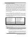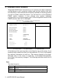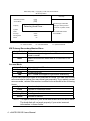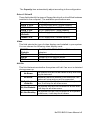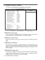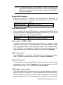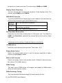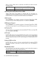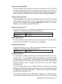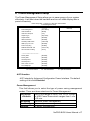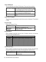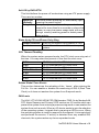
1
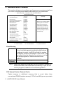
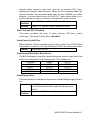
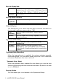
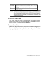
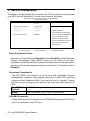
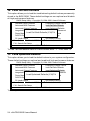
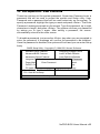
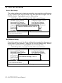
N u P R O-780 BIOS U s e r ’s G u i d e @Copyright 2001 ADLINK Technology Inc. All Rights Reserved. Manual Rev. 1.00: November 12, 2001 The information in this document is subject to change without prior notice in order to improve reliability, design and function and does not represent a commitment on the part of the manufacturer. In no event will the manufacturer be liable for direct, indirect, special, incidental, or consequential damages arising out of the use or inability to use the product or documentation, even if advised of the possibility of such damages. This document contains proprietary information protected by copyright. All rights are reserved. No part of this manual may be reproduced by any mechanical, electronic, or other means in any form without prior written permission of the manufacturer. Trademarks NuPRO is registered trademarks of ADLINK Technology Inc. Other product names mentioned herein are used for identification purposes only and may be trademarks and/or registered trademarks of their respective companies. Table of Contents 1. BIOS SETUP INTRODUCTION ........................................ 1 2. STANDARD CMOS FEATURES........................................ 2 3. ADVANCED BIOS FEATURES .......................................... 6 4. ADVANCED CHIPSET FEATURES................................. 10 5. INTEGRATED PERIPHERALS........................................ 13 6. POWER MANAGEMENT SETUP.................................... 17 7. PNP/PCI CONFIGURATION............................................ 20 8. PC HEALTH STATUS ...................................................... 22 9. FREQUENCY/VOLTAG E CONTROL ............................. 23 10. LOAD FAIL-SAFE DEFAULTS....................................... 24 11. LOAD OPTIMIZED DEFAULTS..................................... 24 12. SET SUPERVISOR / USER PASSWORD..................... 25 13. SAVE & EXIT SETUP ..................................................... 26 1. BIOS Setup Introduction The Award BIOS provides a Setup utility program for specifying the system configurations and settings. The BIOS ROM of the system stores the Setup utility. When you turn on the computer, the Award BIOS is immediately activated. Pressing the <Del> key immediately allows you to enter the Setup utility. If you are a little bit late pressing the <Del> key, POST (Power On Self Test) will continue with its test routines, thus preventing you from invoking the Setup. If you still wish to enter Setup, restart the system by pressing the “Reset” button or simultaneously pressing the <Ctrl>, <Alt> and <Delete> keys. You can also restart by turning the system Off and back On again. The following message will appear on the screen: Press <DEL> to Enter Setup In general, you press the arrow keys to highlight items, <Enter> to select, the <PgUp> and <PgDn> keys to change entries, <F1> for help and <Esc> to quit. When you enter the Setup utility, the Main Menu screen will appear on the screen. The Main Menu allows you to select from various setup functions and exit choices. CMOS Setup Utility – Copyright (C) 1984-2001 Award Software Standard CMOS Features Frequency/Voltage Control Advanced BIOS Features Load Fail-Safe Defaults Advanced Chipset Features Load Optimized Defaults Integrated Peripherals Set Supervisor Password Power Management Setup Set User Password PnP/PCI Configurations Save & Exit Setup PC Health Status ESC : Quit Exit Without Saving F9 : Menu in BIOS á â à ß : Selec t Item F10 : Save & Exit Setup Time, Date, Hard Disk Type… The section below the setup items of the Main Menu displays the control keys for this menu. Another section at the bottom of the Main Menu just below the control keys section displays informati on on the currently highlighted item in the list. NOTE: 1. After making and saving system changes with Setup, you find that your computer cannot boot, the Award BIOS supports an override to the CMOS settings that resets your system to its default. 2. We strongly recommend that you avoid making any changes to the chipset defaults. These defaults have been carefully chosen by both Award and your system manufacturer to provide the absolute maximum performance and reliability. NuPRO BIOS Users Manual • 1 2. Standard CMOS Features "Standard CMOS Setup" item allows you to record some basic hardware configurations in your computer system and set the system clock and error handling. If the motherboard is already installed in a working system, you will not need to select this option. You will need to run the Standard CMOS option, however, if you change your system hardware configurations, the onboard battery fails, or the configuration stored in the CMOS memory was lost or damaged. CMOS Setup Utility – Copyright (C) 1984-2001 Award Software Standard CMOS Features Date (mm : dd : yy) Mon, Jan 1 2000 Time (hh : mm : ss) 16 : 34 : 3 IDE Primary Master [None] IDE Primary Slave [None] IDE Secondary Master [None] IDE Secondary Slave [None] Drive A [1.44M, 3.5 in.] Drive B [None] Video [EGA/VGA] Halt On [All, But Keyboard] Item Help Menu Level Base Memory 640K Extended Memory 64448K Total Memory 65536K á â à ß : Move Enter : Select +/-/PU/PD : Value F10 : Save ESC : Exit F1 : General Help F5 : Previous Values F6 : Fail-Safe Defaults F7 : Optimized Defaults At the bottom of the menu are the control keys for use on this menu. If you need any help in each item field, you can press the <F1> key. It will display the relevant information to help you. The memory display at the lower left-hand side of the menu is read-only. It will adjust automatically according to the memory changed. The following describes each item of this menu. Date The date format is: Day Month Date Year Sun to Sat (read only) 1 to 12 1 to 31 1994 to 2079 2 • NuPRO BIOS Users Manual To set the date, highlight the “Date” field and use the PageUp/ PageDown or +/- keys to set the current date. Time The time format is: Hour Minute Second 00 to 23 00 to 59 00 to 59 To set the time, highlight the "Time" field and use the <PgUp>/ <PgDn> or +/- keys to set the current time. IDE Primary/Secondary Master/Slave The onboard PCI IDE connectors provide Primary and Secondary channels for connecting up to four IDE hard disks or other IDE devices. Each channel can support up to two hard disks; the first is the “Master” and the second is the “Slave”. Award CMOS setup utility provides a sub-menu to enter the specifications for a hard disk drive. CMOS Setup Utility – Copyright (C) 1984-2001 Award Software IDE Primary Master IDE HDD Auto-Detection [Press Enter] IDE Primary Master [Auto] Access Mode [Auto] Capacity 6480 MB Cylinder 12556 Item Help Menu Level Selects the type of fixed disk. ‘User type’ will let you select the number of cylinders, heads, Head 16 Precomp 65535 Landing Zone 12556 Sector etc. Note: PRECOMP=65535 means NONE ! 63 á â à ß : Move Enter : Select +/-/PU/PD : Value F10 : Save ESC : Exit F1 : General Help F5 : Previous Values F6 : Fail-Safe Defaults F7 : Optimized Defaults The following describes each item of this menu. IDE HDD Auto-Detection This item is used to detect the type of hard drive. It will assign the cylinder, head, precomp, landing zone, and sector to the hard drive. NuPRO BIOS Users Manual • 3 CMOS Setup Utility – Copyright (C) 1984-2001 Award Software IDE Primary Master IDE HDD Auto-Detection [Press Enter] IDE Primary Master [Auto] Access Mode [Auto] Item Help Menu Level Selects the type of fixed disk. *Capacity 6480 MB Detecting Hard Drive… *Cylinder 12556 *Head 16 *Precomp 65535 *Landing Zone 12556 *Sector ‘User type’ will let you select the number of cylinders, heads, etc. Note: PRECOMP=65535 means NONE ! 63 á â à ß : Move Enter : Select +/-/PU/PD : Value F10 : Save ESC : Exit F1 : General Help F5 : Previous Values F6 : Fail-Safe Defaults F7 : Optimized Defaults IDE Primary/Secondary Master/Slave Auto <Default> BIOS will auto detect the hard disk type. Manual User can assigns the type of hard disk when the access mode is normal. None Selects this selection when there is no hard disk in the system. Access Mode Auto <Default> Normal Large LBA Auto-detect the HDD mode HD < 528MB For MS-DOS only HD > 528MB and supports Logical Block Addressing If your hard disk drive type is not matched or listed, you can use normal access mode to define your own drive type manually. If you select normal access mode, related information is asked to be entered to the following items. Cylinder Head Precomp Landing Zone Sector Number of cylinders Number of read/write heads Write precompensation Landing zone Number of sectors NOTE: The specifications of your drive must match with the drive table. The hard disk will not work properly if you enter incorrect information in these fields. 4 • NuPRO BIOS Users Manual The Capacity item automatically adjust according to the configuration. Drive A / Drive B These fields identify the types of floppy disk drive A or drive B that hasbeen installed in the computer. The available specifications are: None 360KB 5.25 in. 1.2MB 5.25 in. 720KB 3.5 in. 1.44MB 3.5 in. <Default> 2.88MB 3.5 in. No floppy drive be installed 5.25 inch floppy drive, 360KB capacity 5.25 in. floppy drive, 1.2MB capacity 3.5 in. floppy drive, 720KB capacity 3.5 in. floppy drive, 1.44MB capacity 3.5 in. floppy drive, 2.88MB capacity Video This field selects the type of video display card installed in your system. You can choose the following video display cards. EGA/VGA <Default> CGA 40 CGA 80 MONO For EGA, VGA, SEGA, SVGA or PGA monitor adapters. Power up in 40 column mode. Power up in 80 column mode. For Hercules or MDA adapters. Halt On This field determines whether the system will halt if an error is detected during power up. The system boot will not be halted for any error that may be detected. All Errors Whenever the BIOS detects a non-fatal error, the system will stop and you will be prompted. All, But Keyboard The system boot will not be halted for a keyboard <Default> error; it will stop for all other errors The system boot will not be halted for a disk error; All, But Diskette it will stop for all other errors. The system boot will not be halted for a keyboard All, But Disk/Key or disk error; it will stop for all others. No Errors NuPRO BIOS Users Manual • 5 3. Advanced BIOS Features This section allows you to configure and improve your system and allows you to set up some system features according to your preference. CMOS Setup Utility – Copyright (C) 1984-2001 Award Software Advanced BIOS Features Virus Warning [Disabled] CPU Internal Cache [Enabled] External Cache [Enabled] CPU L2 Cache ECC Checking [Enabled] Quick Power On Self Test [Disabled] Allows you to choose the VIRUS First Boot Device [Floppy] warning feature for IDE Hard Second Boot Device [HDD-0] Disk boot sector protection. Third Boot Device [LS120] If this function is enabled and Boot Other Device [Enabled] someone attempt to write data Swap Floppy Drive [Disabled] into this area, BIOS will show Boot Up Floppy Seek [Enabled] a warning message on screen Boot Up NumLock Status [On] and alarm beep Gate A20 Option Typematic Rate Setting Typematic Rate (Chars/Sec) Typematic Delay (Msec) Security Option OS Select For DRAM > 64MB Summary Screen Show [Fast] [Disabled] 6 250 [Setup] [Non-OS2] [Disabled] Item Help Menu Level á â à ß : Move Enter : Select +/-/PU/PD : Value F10 : Save ESC : Exit F1 : General Help F5 : Previous Values F6 : Fail-Safe Defaults F7 : Optimized Defaults Virus Warning Enabled Disabled <Default> This item protects the boot sector and partition table of your hard disk against accidental modifications. If an attempt is made, the BIOS will halt the system and display a warning message. If this occurs, you can either allow the operation to continue or run an anti-virus program to locate and remove the problem. No warning message appears NOTE: Many disk diagnostic programs, which attempt to access the boot sector table, can cause the virus warning. If you will run such a program, disable the Virus Warning feature. CPU Internal Cache / External Cache Cache memory is additional memory that is much faster than conventional DRAM (system memory). CPUs from 486-type on up contain 6 • NuPRO BIOS Users Manual internal cache memory, and most, but not all, modern PCs have additional (external) cache memory. When the CPU requests data, the system transfers the requested data from the main DRAM into cache memory, for even faster access by the CPU. These items allow you to enable (speed up memory access) or disable the cache function. Enabled Open CPU Internal Cache / External Cache <Default> Disabled Close CPU Internal Cache / External Cache CPU L2 Cache ECC Checking This option enables the level 2 cache memory ECC(error check correction). The default of this item is Enabled. Quick Power On Self Test When enabled, this field speeds up the Power On Self Test (POST) after the system is turned on. If it is set to Enabled, BIOS will skip some items. Enabled Enable quick POST First/Second/Third/Other Boot Device The BIOS attempts to load the operating system from the devices in the sequence selected in the following items. The settings are: Disabled HDD-0 HDD-1 ZIP100 USB-CDROM Floppy SCSI HDD-2 USB-FDD LAN LS120 CDROM HDD-3 USB-ZIP Swap Floppy Drive This item allows you to determine whether to enable Swap Floppy Drive or not. Enabled Disabled <Default> The BIOS swaps floppy drive assignments so that Drive A becomes Drive B, and Drive B becomes Drive A. Disable the BIOS to swap floppy drive NuPRO BIOS Users Manual • 7 Boot Up Floppy Seek Enabled The BIOS will seek whether or not the floppy drive installed has 40 or 80 tracks. 360K type has 40 tracks while 760K, 1.2M and 1.44M all have 80 tracks Disabled BIOS will not search the type of floppy disk drive by <Default> track number Boot Up NumLock Status On Keypad is number keys <Default> Off Keypad is arrow keys Gate A20 Option This field allows you to select how Gate A20 is worked. Gate A20 is a device used to address memory above 1 MB. Fast The A20 signal controlled by chipset specific <Default> method Normal The A20 signal controlled by keyboard controller or chipset hardware Typematic Rate Setting Enabled Enable typematic rate and typematic delay programming Disabled Disable typematic rate and typematic delay <Default> programming. The s ystem BIOS will use default value of these 2 items and the default controlled by keyboard Typematic Rate (Chars/Sec) When the typematic rate is enabled, the system registers repeated keystrokes speeds. You can select speed range from 6 to 30 characters per second. By default, this item is set to 6. Typematic Delay (Msec) When the typematic rate is enabled, this item allows you to set the time interval for displaying the first and second characters. By default, this item is set to 250msec. Security Option This field allows you to limit access to the System and Setup. 8 • NuPRO BIOS Users Manual Setup the system always boots up and prompts for the <Default> Supervisor Password only when the Setup utility is called up System the system prompts for the User Password every time you boot up NOTE: To disable security, select PASSWORD SETTING at Main Menu and then you will be asked to enter the password. If you do not type anything and just press <Enter> key, it will disable security. Once the security is disabled, you can boot up the system and access to Setup freely. OS Select for DRAM > 64MB This option allows the system to access greater than 64MB of DRAM memory when used with OS/2 that depends on certain BIOS calls to access memory. The default setting is Non-OS/2. Summary Screen Show When POST, BIOS will lists the PCI devices and system configurations on the screen to tell user what configurations are on the system. This item allows you to decide whether system shows the configuration or not. The default is Enabled. NuPRO BIOS Users Manual • 9 4. Advanced Chipset Features This Setup menu controls the configuration of the chipset. CMOS Setup Utility – Copyright (C) 1984-2001 Award Software Advanced Chipset Features SDRAM CAS Latency Time [Auto] SDRAM Cycle Time Tras/Trc [Auto] SDRAM RAS-to-CAS Delay [Auto] SDRAM RAS Precharge Time [Auto] System BIOS Cacheable [Disabled] Video BIOS Cacheable [Disabled] Memory Hole At 15M-16M [Disabled] CPU Latency Timer [Disabled] Delayed Transaction [Enabled] AGP Graphics Aperture Size [64MB] Display Cache Frequency [100 MHz] FWH Write Protection [Disabled] On-Chip Video Window Size [64MB] Item Help Menu Level * Onboard Display Cache Setting * CAS# Latency [3] Paging Mode Control [Open] RAS-to-CAS Override [by CAS# LT] RAS# Timing [Fast] RAS# Precharge Timing [Fast] á â à ß : Move Enter : Select +/-/PU/PD : Value F10 : Save ESC : Exit F1 : General Help F5 : Previous Values F6 : Fail-Safe Defaults F7 : Optimized Defaults SDRAM CAS Latency Time When synchronous DRAM is installed, the number of clock cycles of CAS latency depends on the DRAM timing. The default is Auto. SDRAM Cycle Time Tras/Trc Select the number of SCLKs for an access cycle. The default setting is Auto. SDRAM RAS-to-CAS Delay This field lets you insert a timing delay between the CAS and RAS strobe signals, used when DRAM is written to, read from, or refreshed. This field applies only when synchronous DRAM is installed in the system. The default is Auto. SDRAM RAS Precharge Time If an insufficient number of cycles is a llowed for the RAS to accumulate its charge before DRAM refresh, the refresh may be incomplete and the DRAM may fail to retain data. The default is Auto. 10 • NuPRO BIOS Users Manual NOTE: All related settings of SDRAM are set to Auto. It means that all parameters of SDRAM are decided by the SPD value of Memory. BIOS will use the optimized settings to configure the SDRAM that on your system. System BIOS Cacheable When this function is enabled, the BIOS ROM’s addresses at F0000H-FFFFFH will be duplicated into the SRAM. It will work with the cache controller that is enabled. Enabled <Default> Disabled BIOS access cached BIOS access not cached Video BIOS Cacheable As with caching the system BIOS above, enabling the Video BIOS cache will cause access to video BIOS addressed at C0000H to C7FFFH to be cached, it the cache controller is also enabled. Enabled <Default> Disabled Video BIOS access cached Video BIOS access not cached Memory Hole at 15MB - 16MB In order to improve performance, certain space in memory can be reserved for ISA cards. This field allows you to reserve 15MB to 16MB memory address space to ISA expansion cards. This makes memory from 15MB and up unavailable to the system. Expansion cards can only access memory up to 16MB. By default, this field is set to Disabled. CPU Latency Timer When Disabled, a “deferrable” CPU cycle will be deferred immediately after the chipset receives another ADS#. The default is Disabled. Delayed Transaction The chipset has an embedded 32-bit posted write buffer to support delay transactions cycles. Select Enabled to support compliance with PCI specification version 2.1. The default setting is Enabled. AGP Graphics Aperture Size This field determines the effective size of the Graphic Aperture used for a particular GMCH configuration. It can be updated by the GMCH-specific BIOS configuration sequence before the PCI standard bus enumeration sequence takes place. If it is not updated then a default value will select NuPRO BIOS Users Manual • 11 an aperture of maximum size. The choices are 32MB and 64MB. Display Cache Frequency You can use this item to select the frequency of the display cache. The choices are 100MHz and 133MHz. FWH Write Protection To protect the BIOS from destroying by some reasons, this item lets user to select the protection type to avoid BIOS errors. Disabled User can flash BIOS anywhere. <Default> TBL_Only Top Block Lock, top block area doesn’t change when flashing the new BIOS. Enabled User can’t flash the newer BIOS file. On-Chip Video Window Size Select the on-chip video window size for VGA driver use. The default is 64MB. If the Disabled is selected, the system will not boot with no other VGA card. Followings are the setting of onboard display cache timing. CAS# Latency Select the local memory clock periods. The choice : 2, 3. Paging Mode Control Select the paging mode control. It will let memory controller to leave memory pages open or close. RAS-to-CAS Override Select the display cache clock periods control. Default is determined by the value of CL(CAS# Latency). RAS# Timing This item control RAS# active to Protegra, and refresh to RAS# active delay (in local memory clocks). RAS# Precharge Timing This item controls RAS# precharge (in local memory clocks). 12 • NuPRO BIOS Users Manual 5. Integrated Peripherals This option sets your hard disk configuration, mode and port. CMOS Setup Utility – Copyright (C) 1984-2001 Award Software Integrated Peripherals On-Chip Primary PCI IDE [Enabled] On-Chip Secondary PCI IDE [Enabled] IDE Primary Master PIO [Auto] IDE Primary Slave PIO [Auto] IDE Secondary Master PIO [Auto] IDE Secondary Slave PIO [Auto] IDE Primary Master UDMA [Auto] IDE Primary Slave UDMA [Auto] IDE Secondary Master UDMA [Auto] IDE Secondary Slave UDMA [Auto] USB Controller [Enabled] USB Keyboard Support [Disabled] Init Display First [PCI Slot] AC97 Audio [Auto] Onboard 82559 Lan Chip [Enabled] IDE HDD Block Mode [Enabled] Onboard Lan Boot ROM [Disabled] Onboard FDC Controller [Enabled] Onboard Serial Port 1 [3F8/IRQ4] Onboard Serial Port 2 [2E8/IRQ3] UART Mode Select [Normal] RxD , TxD Active [Hi,Lo] IR Transmission Delay [Enabled] UR2 Duplex Mode [Half] Use IR Pins [IR-Rx2] Onboard Parallel Port [378/IRQ7] Parallel Port Mode [SPP] EPP Mode Select [Epp1.9] ECP Mode Use DMA [3] Item Help Menu Level á â à ß : Move Enter : Select +/-/PU/PD : Value F10 : Save ESC : Exit F1 : General Help F5 : Previous Values F6 : Fail-Safe Defaults F7 : Optimized Defaults On-Chip Primary/Secondary PCI IDE The integrated peripheral controller contains an IDE interface with support for two IDE channels. Select Enabled to activate each channel separately. IDE Primary/Secondary Master/Slave PIO These fields allow your system hard disk controller to work faster. Rather than have the BIOS issue a series of commands that transfer to or from the disk drive, PIO (Programmed Input/Output) allows the BIOS to communicate with the controller and CPU directly. The system supports five modes, numbered from 0 to 4, which primarily NuPRO BIOS Users Manual • 13 differ in timing. When Auto is selected, the BIOS will select the best available mode. Auto<Default> Mode0~Mode4 Auto select which mode that BIOS communicates with the controller and CPU User define the PIO mode IDE Primary/Secondary Master/Slave UDMA These fields allow your system to improve disk I/O throughput to 33Mb/sec with the Ultra DMA/33 feature. Intel 815E chipset supports up to ATA100 feature. The options are Auto<Default> and Disabled. USB Controller Select Enabled if your system contains a Universal Serial Bus (USB) controller and you have USB peripherals. The default is Enabled. USB Keyboard Support Select Enabled if your system contains a Universal Serial Bus (USB) controller and you want to use a USB keyboard under DOS environment. Init Display First This item allows you to decide to activate whether PCI Slot or on-chip VGA first. The default is PCI Slot. AC97 Audio NuPRO-780 support an optional AC97 Audio module. User can decide to add an AC97 module on NuPRO-780 board. When setting is Auto, BIOS will auto detect the codec of AC97 and configures it if there has an AC97 module. Onboard 82559 Lan Chip NuPRO-780 has a function that can enable/disable the onboard 82559 Lan chip to decide if you want to use two Lans or not. The default is Enabled. IDE HDD Block Mode This field allows your hard disk controller to use the fast block mode to transfer data to and from your hard disk drive. Enabled<Default> Disabled IDE controller uses block mode IDE controller uses standard mode 14 • NuPRO BIOS Users Manual Onboard Lan Boot ROM This item allows you to decide to support PXE function or not. The PXE function can lets system boot from a network environment. To support it, it also need a DHCP server to link the system. We only support this function from the onboard 82562EM Lan chip.The default setting is Disabled. Onboard FDC Controller Select Enabled if your system has a floppy disk controller (FDC) installed on the system and you wish to use it. If you install an add-in FDC or the system has no floppy drive, select Disabled in this field. This option allows you to select the onboard FDD port. Onboard Serial Port 1/2 These fields allow you to select the onboard serial ports and their addresses. The default values for these ports are: Serial Port 1 Serial Port 2 3F8 / IRQ4 2F8 / IRQ3 UART Mode Select This field determines the UART mode in your computer. The settings are Normal, IrDA and ASKIR. The default value is Normal. Onboard Parallel Port These fields allow you to select the onboard parallel ports and their addresses. The default value for this port is: Parallel Port 378H/IRQ7 Parallel Port Mode To operate the onboard parallel port as Standard Parallel Port only, choose “SPP”. To operate the onboard parallel port in the EPP modes simultaneously, choose “EPP”. By choosing “ECP”, the onboard parallel port will operate in ECP mode only. Choosing “ECP+EPP” will allow the onboard parallel port to support both the ECP and EPP modes simultaneously. The ECP mode has to use the DMA channel, so choose the onboard parallel port with the ECP feature. After selecting it, the following message will appear “ECP Mode Use DMA”. At this time, the user can choose between DMA channels 3 or 1. The onboard parallel port is EPP Spec. compliant, so after the user chooses the onboard parallel port with the EPP function, the following NuPRO BIOS Users Manual • 15 message will be displayed on the screen: ”EPP Mode Select”. At this time either EPP 1.7 spec. or EPP 1.9 spec. can be chosen. 16 • NuPRO BIOS Users Manual 6. Power Management Setup The Power Management Setup allows you to save energy of your system effectively. It will shut down the hard disk and turn off video display after a period of inactivity. CMOS Setup Utility – Copyright (C) 1984-2001 Award Software Power Management Setup ACPI Function [Enabled] Power Management [User Define] Video Off Method [DPMS] Video Off In Suspend [Yes] Suspend Type [Stop Grant] Suspend Mode [Disabled] HDD Power Down [Disabled] Soft-Off by PWR-BTTN [Instant-Off] Wake-Up by PCI card [Disabled] Power On by Ring [Enabled] PWRON After PWR-Fail CPU Thermal-Throttling [Former-Sts] [50.0%] Item Help Menu Level ** Reload Global Timer Events ** Primary IDE 0 [Disabled] Primary IDE 1 [Disabled] Secondary IDE 0 [Disabled] Secondary IDE 1 [Disabled] FDD, COM, LPT Port [Disabled] PCI PIRQ[A-D]# [Disabled] á â à ß : Move Enter : Select +/-/PU/PD : Value F10 : Save ESC : Exit F1 : General Help F5 : Previous Values F6 : Fail-Safe Defaults F7 : Optimized Defaults ACPI function ACPI stands for Advanced Configuration Power Interface. The default setting of this field Disabled. Power Management This field allows you to select the type of power saving management modes. There are three selections for Power Management. User Define <Default> Min Saving Max Saving Disabled Each of the ranges is from 1 min. to 1hr. Except for HDD Power Down which ranges from 1 min. to 15 min. Minimum power management Maximum power management. No power management. NuPRO BIOS Users Manual • 17 Video Off Method This field defines the Video Off features. There are three options. V/H SYNC + Blank This selection will cause the system to turn off the Vertical and horizontal synchronization ports and Write blanks to the video buffer DPMS Allows the BIOS to control the video display card if it supports the DPMS feature Blank Screen This option only writes blanks to the video buffer Video Off In Suspend This determines the manner in which the monitor is blanked. The default is Yes. Suspend Type Select the Suspend Type. PWRON Suspend Stop Grant <Default> Use the power button to decide whether the system is in suspend or not. When the system is idle, it will be in suspend mode. Suspend Mode When enabled, and after the set time of system inactivity, all devices except the CPU will be shut off. Disabled 1 Hour 40 min 30 min 20 min 12 min 8 min 4 min 2 min 1 min Disable the Suspend mode After 1 hour of system inactivity, enter Suspend mode After 40 min of system inactivity, enter Suspend mode After 30 min of system inactivity, enter Suspend mode After 20 min of system inactivity, enter Suspend mode After 12 min of system inactivity, enter Suspend mode After 8 min of system inactivity, enter Suspend mode After 4 min of system inactivity, enter Suspend mode After 2 min of system inactivity, enter Suspend mode After 1 min of system inactivity, enter Suspend mode HDD Power Down When enabled, and after the set time of system inactivity, the hard disk drive will be powered down while all other devices remain active. Disabled <Default> 1 min ~ 15 min Don’t Enter the HDD power down mode After the set time of system inactivity, HDD power down 18 • NuPRO BIOS Users Manual Soft-Off by PWR-BTTN This field defines the power-off mode when using an ATX power supply. There are two modes: Instant-Off The mode allows powering off immediately upon <Default> pressing the power button Delay 4 Sec The system powers o ff when the power button is pressed for more than four seconds or places the system in a very low-power-usage state, with only enough circuitry receiving power to detect power button activity. Wake-Up by PCI card/Power On by Ring Enabled <Default> Wake up the system from modem or LAN Disabled Disable the modem or LAN to wake up the system CPU Thermal-Throttling When the system enters suspend mode, the CPU clock runs only part of the time. You may select the percent of time that the clock runs. 87.5% 75.0% 62.5% 50.0% <Default> 37.5% 25.0% 12.5% 87.5% time that the CPU clock runs 75.0% time that the CPU clock runs 62.5% time that the CPU clock runs 50.0% time that the CPU clock runs 37.5% time that the CPU clock runs 25.0% time that the CPU clock runs 12.5% time that the CPU clock runs Reload Global Timer Events This section determines the reloading of the ‘timers’ after entering the Full On. You can enable or disable the monitoring of IRQ 8 (Real Time Clock) so it does not awaken the system from Suspend mode. PM Events The VGA, LPT & COM, HDD & FDD, DMA/master, PWR-On by Modem/LAN, RTC Alarm Resume and Primary INTR section are I/O events which can prevent the system from entering a power saving mode or can awaken the system from such a mode. When an I/O device wants to gain the attention of the operating system, it signals this by causing an IRQ to occur. When the operating system is ready to respond to the request, it interrupts itself and performs the service. If activity is detected from any enabled IRQ channels, the system wakes up from suspended mode. NuPRO BIOS Users Manual • 19 7. PNP/PCI Configuration This option configures the PCI bus system. All PCI bus systems on the system use INT#, thus all installed PCI cards must be set to this value. CMOS Setup Utility – Copyright (C) 1984-2001 Award Software PnP/PCI Configurations Reset Configuration Data [Enabled] Resources Controlled By [Auto(ESCD)] IRQ Resources Press Enter DMA Resources Press Enter PCI/VGA Palette Snoop [Disabled] Item Help Menu Level Default is Disabled. Select Enabled to reset Extended System Configuration Data(ESCD) when you exit setup if you have installed a new add-on and the system reconfiguration has caused such a serious conflict that the OS cannot boot á â à ß : Move Enter : Select +/-/PU/PD : Value F10 : Save ESC : Exit F1 : General Help F5 : Previous Values F6 : Fail-Safe Defaults F7 : Optimized Defaults Reset Configuration Data Normally, you leave this field Disabled. Select Enabled to reset Extended System Configuration Data (ESCD) when you exit Setup if you have installed a new add-on and the system reconfiguration has caused such a serious conflict that the operating system can not boot. The default value is Disabled. Resources Controlled by This PnP BIOS can configure all of the boot and compatible devices automatically. However, this capability needs you to use a PnP operating system such as Windows 95/98. If you set this field to “manual” choose specific resources by going into each of the sub menu that follows this field. Auto(ESCD) <Default> Manual PnP BIOS configure all compatible devices automatically User can assign IRQ & DMA to the devices IRQ/DMA Resources These fields allow you to determine the IRQ/DMA assigned to the ISA bus and is not available to any PCI slot. 20 • NuPRO BIOS Users Manual PCI/VGA Palette Snoop Some non-standard VGA display cards may not show colors properly. This field allows you to set whether MPEG ISA/VESA VGA cards can work with PCI/VGA or not. Enabled Disabled <Default> PCI/VGA can work with MPEG ISA/VESA VGA card PCI/VGA can not work with MPEG ISA/VESA VGA card NuPRO BIOS Users Manual • 21 8. PC Health Status CMOS Setup Utility – Copyright (C) 1984-2001 Award Software PC Health Status CPU Warning Temperature [Disabled] Item Help Current System Temp. Current CPU Temperature Menu Level Current System2 Temperature Current CPU FAN Speed Select the limit of CPU VCORE temperature. When CPU + 2.5V Temperature exceeds the + 3.3V limit. System speaker will +5V beep for a warning alarm! +12 V -12 V VBAT(V) 5VSB(V) á â à ß : Move Enter : Select +/-/PU/PD : Value F10 : Save ESC : Exit F1 : General Help F5 : Previous Values F6 : Fail-Safe Defaults F7 : Optimized Defaults CPU Warning Temperature This field sets the threshold temperature at which an alert is sounded through the system’s speaker. The CPU temperature is monitored by the onboard thermal sensor to prevent the CPU from overheating. Current System/CPU Temperature/System2 Temperature/Current CPU Fan Speed/ VCORE / +2.5V/+3.3V/+5V/+12V/-12V/VBAT(V)/5VSB(V) These items will show the CPU/FAN/System voltage chart and FAN speed. 22 • NuPRO BIOS Users Manual 9. Frequency/Voltage Control CMOS Setup Utility – Copyright (C) 1984-2001 Award Software Frequency/Voltage Control Auto Detect DIMM/PCI Clk Enabled CPU Clock/Spread Spectrum Default Item Help Menu Level á â à ß : Move Enter : Select +/-/PU/PD : Value F10 : Save ESC : Exit F1 : General Help F5 : Previous Values F6 : Fail-Safe Defaults F7 : Optimized Defaults Auto Detect DIMM/PCI Clk This item allows you to enable/disable auto detect DIMM/PCI Clock. The default is Disabled. CPU Clock/Spread Spectrum This item allows you to set the CPU Clock/spread Spectrum. NuPRO BIOS Users Manual • 23 10. Load Fail-Safe Defaults This option allows you to load the troubleshooting default values permanently stored in the BIOS ROM. These default settings are non-optimal and disable all high-performance features. CMOS Setup Utility – Copyright (C) 1984-2001 Award Software Standard CMOS Features Frequency/Voltage Control Advanced BIOS Features Load Fail-Safe Defaults Advanced Chipset Features Load Optimized Defaults Integrated Peripherals Set Supervisor Password Load Fail-Safe Defaults (Y/N)? N Power Management Setup Set User Password PnP/PCI Configurations Save & Exit Setup PC Health Status Exit Without Saving Esc : Quit F9 : Menu in BIOS F10 : Save & Exit Setup á â à ß : Select Item Load Fail-Safe Defaults To load Fail-Safe defaults value to CMOS SRAM, enter “Y”. If not, enter “N”. 11. Load Optimized Defaults This option allows you to load the default values to your system configuration. These default settings are optimal and enable all high performance features. CMOS Setup Utility – Copyright (C) 1984-2001 Award Software Standard CMOS Features Frequency/Voltage Control Advanced BIOS Features Load Fail-Safe Defaults Advanced Chipset Features Load Optimized Defaults Integrated Peripherals Set Supervisor Password Load Optimized Defaults (Y/N)? N Power Management Setup Set User Password PnP/PCI Configurations Save & Exit Setup PC Health Status Exit Without Saving Esc : Quit F9 : Menu in BIOS F10 : Save & Exit Setup á â à ß : Select Item Load Optimized Defaults To load Optimized defaults value to CMOS SRAM, enter “Y”. If not, enter “N”. 24 • NuPRO BIOS Users Manual 12. Set Supervisor / User Password These two options set the system password. Supervisor Pas sword sets a password that will be used to protect the system and Setup utility. User Password sets a password that will be used exclusively on the system. To specify a password, highlight the type you want and press <Enter>. The Enter Password: message prompts on the screen. Type the password, up to eight characters in length, and press <Enter>. The system confirms your password by asking you to type it again. After setting a password, the screen automatically returns to the main screen. To disable a password, just press the <Enter> key when you are prompted to enter the password. A message will confirm the password to be disabled. Once the password is disabled, the system will boot and you can enter Setup freely. CMOS Setup Utility – Copyright (C) 1984-2001 Award Software Standard CMOS Features Advanced BIOS Features Advanced Chipset Features Integrated Peripherals Power ManagementEnter Setup Password: PnP/PCI Configurations PC Health Status Esc : Quit F9 : Menu in BIOS F10 : Save & Exit Setup Frequency/Voltage Control Load Fail-Safe Defaults Load Optimized Defaults Set Supervisor Password Set User Password Save & Exit Setup Exit Without Saving á â à ß : Select Item Set Supervisor Password NuPRO BIOS Users Manual • 25 13. Save & Exit Setup Save & Exit Setup This option allows you to determine whether to accept the modifications or not. Typing Y will quit the setup utility and save all changes into the CMOS memory. Typing N will return to Setup utility. CMOS Setup Utility – Copyright (C) 1984-2001 Award Software Standard CMOS Features Frequency/Voltage Control Advanced BIOS Features Load Fail-Safe Defaults Advanced Chipset Features Load Optimized Defaults Integrated Peripherals Set Supervisor Password Save Setup to CMOS and ExitSet (Y/N)? Power Management User N Password PnP/PCI Configurations Save & Exit Setup PC Health Status Exit Without Saving Esc : Quit F9 : Menu in BIOS F10 : Save & Exit Setup á â à ß : Select Item Save & Exit Setup Exit Without Saving Select this option to exit the Setup utility without saving the changes you have made in this session. Typing Y will quit the Setup utility without saving the modifications. Typing N will return to Setup utility. CMOS Setup Utility – Copyright (C) 1984-2001 Award Software Standard CMOS Features Frequency/Voltage Control Advanced BIOS Features Load Fail-Safe Defaults Advanced Chipset Features Load Optimized Defaults Integrated Peripherals Set Supervisor Password Power Management Setup Set User Quit Without Saving (Y/N)? N Password PnP/PCI Configurations Save & Exit Setup PC Health Status Exit Without Saving Esc : Quit F9 : Menu in BIOS F10 : Save & Exit Setup á â à ß : Select Item Exit without Saving 26 • NuPRO BIOS Users Manual