1
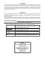
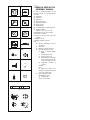
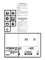
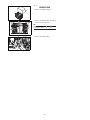
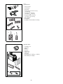
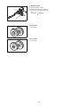
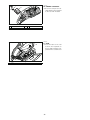
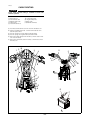
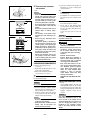
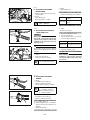
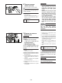
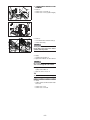
YFM90RY
ASSEMBLY MANUAL
LIT-11666-22-13
43D-F8107-10
EBA00002
FOREWORD
This Assembly Manual contains the information required for the correct assembly of this Yamaha machine prior to delivery to the customer. Since some external parts of the machine have been removed
at the Yamaha factory for the convenience of packing, assembly by the Yamaha dealer is required. It
should be noted that the assembled machine should be thoroughly cleaned, checked, and adjusted prior to delivery to the customer.
EBA00003
IMPORTANT
The service specifications given in this assembly manual are based on the model as manufactured.
Modifications and significant changes in specifications and/or procedures will be forwarded to authorized Yamaha dealers.
The procedures below are described in the order that the procedures are carried out correctly and completely. Failure to do so can result in poor performance and possible harm to the machine and/or rider.
CONCERNING CRATE DAMAGE:
Follow the instructions in the Dealer Warranty Handbook, Procedure Section.
Particularly important information is distinguished in this manual by the following notations:
This is the safety alert symbol. It is used to alert you to potential
personal injury hazards. Obey all safety messages that follow this
symbol to avoid possible injury or death.
WARNING
A WARNING indicates a hazardous situation which, if not avoided,
could result in death or serious injury.
NOTICE
A NOTICE indicates special precautions that must be taken to avoid
damage to the vehicle or other property.
TIP
A TIP provides key information to make procedures easier or clearer.
* Product and specifications are subject to change without notice.
YFM90RY
ASSEMBLY MANUAL
©2008 by Yamaha Motor Corporation, U.S.A.
1st edition, July 2008
All rights reserved.
Any reprinting or unauthorized use
without the written permission of
Yamaha Motor Corporation, U.S.A.
is expressly prohibited.
Printed in U.S.A.
P/N LIT-11666-22-13
(1)
EBA01001
(2)
(4)
(5)
(6)
(7)
(8)
(9)
(10)
T.
(3)
SYMBOLS USED IN THE
ASSEMBLY MANUAL
R.
10
(11)
FWD
(12)
UP
(13)
(14)
(15)
D
d
d
D d
d
In order to simplify descriptions in this
assembly manual, the following symbols
are used:
(1): Filling fluid
(2): Lubricant
(3): Special tool
(4): Tightening torque
(5): Wear limit, clearance
(6): Engine speed
(7): Electrical data
(8): Coat with lithium-soap-based grease.
(9): Tighten to 10 Nm.
(10 Nm = 1.0 m · kg, 7.2 ft · lb)
(10):Towards the front of the machine
(11):Clearance required
(12):Install so that the arrow mark faces
upward.
(13):Apply motor oil.
(14):Made of rubber or plastics
(15):
A: Ref. No. (indicating the order of
operations.)
B: Part name
C: Quantity of parts per machine
D: Place where parts are held
(1): Refer to “PARTS LOCATION”.
V: Stored in plastic bag
C: Stored in carton box
S: Fixed inside the steel frame
and/or contained in the Styrofoam tray (upper or lower)
: Temporarily installed or
secured
Example:
(1)-V
(1) signifies the location of the
parts and V signifies that the part
is stored in a plastic bag.
E: Size or material of parts
d/D: Diameter of part
: Length of part
e.g., 5 = 5 mm (0.2 in)
*
EBA00006
PREPARATION
(1)
(2)
(3)
(4)
To assemble the vehicle correctly, supplies
(e.g. oils, greases, and shop rags) and sufficient working space are required.
Workshop
The workshop where the vehicle is assembled should be clean, spacious, and have
a level floor.
Self-protection
Protect your eyes with suitable safety
glasses or goggles when using compressed air, when grinding or when doing
any operation which may cause particles
to fly off.
Protect hands and feet by wearing safety
gloves and shoes.
EBA00007
(5)
(6)
(7)
SYMBOLS USED ON
TRANSPORT PACKAGE
BAG
(1) Contents of the transport package are
fragile, therefore the package must be
handled with care.
(2) Indicates correct upright position of the
transport package.
(3) Transport package must be kept away
from rain.
(4) Do not step anywhere on the transport
package.
(5) Up to 9 of the transport packages can
be piled up.
(6) Only stack this unit with transport
packages of the same size.
(7) Made of high-density polyethylene.
DO NOT STEP ON
DO NOT STEP ON
TAIWAN
EBA00008
UNPACKING
1
b
a
1. Remove the dustproof bag (1).
a
2. Remove the packing frames (2). (Lift up
and then move to the side.)
TIP
2
2
Remove the plates ( a and b ) while
holding the frame.
3. Remove the bolt (3) (frame).
3
–1–
EBA00009
PARTS LOCATION
(1)
(2)
(3)
(4)
(5)
Carton box 1
Carton box 2
Bubble wrap pack 1
Rear wheels
Front wheels
(A) Right view
(B) Left view
A
2
5
4
B
1
3
5
4
–2–
EBA00010
(1) Cart on box 1
1
1.
2.
3.
4.
2
5.
6.
3
7.
8.
9.
4
Rear carrier bar
Front bumper
Plastic bag
Flange nuts (front and rear wheels)
[d = 10 (0.39)]
Flange bolts (front bumper)
[d = 8 (0.31), = 18 (0.71)]
Flange bolts (rear carrier bar)
[d = 8 (0.31), = 12 (0.47)]
Band (battery)
Tag warning
Tag NER (normalized Emissions Rating)
5
7
6
8
9
I
l
l
I I
l
l
l
l
l
l
l
l
3.5
l l
l
l
l
l
(2) Cart on box 2
1
1.
2.
3.
4.
5.
6.
7.
8.
9.
2
3
Handlebar cover
Battery box
Battery
Electrolyte
Filling funnel
Strip of caps
Plastic bag
Bolts (battery) [d = 5 (0.20),
Nuts (battery) [d = 5 (0.20)]
4
5
6
7
8
9
–3–
= 9 (0.35)]
(3) Bubble wrap pack
1. Rear brake master cylinder
2. Bracket (rear brake master cylinder)
3. Flange bolts (rear brake master cylinder)
[d = 6 (0.24), = 25(0.98)]
1
3
2
1
1
(4) Rear wheels
1. Rear wheels
(5) Front wheels
1. Front wheels
–4–
EBA00012
SETUP PROCEDURES
TIP
After opening the crate, place the ATV on a suitable rack and follow the setup procedures.
Before starting the setup, supply the specified tire pressure to the four wheels.
WARNING
_
This model is equipped with low pressure tires. Refer to “ADJUSTMENTS AND PREDELIVERY SERVICE”.
Perform the setup procedures in the order indicated by the numbers. Always follow the order as shown.
3,4,5
8
9,10,11
7
6
2
1
2
1
–5–
EBA00033
1. FRONT WHEELS
B
A: Install the wheels so that the
air valves are facing out.
B: The arrow mark on the tire
must point toward the rotating
direction of the wheel.
C: Tighten the nuts to specification.
2
C
A
45
Front wheel
2
(5)-S
2
Flange nut
8
(1)-V d = 10 (0.39)
R.
1
T.
1
Nut
45 Nm
(4.5 m · kg, 32.5 ft · lb)
EBA00034
2. REAR WHEELS
A: Install the wheels so that the
air valves are facing out.
B: Tighten the nuts to specification.
T.
2
B
R.
45
1
Nut
45 Nm
(4.5 m · kg, 32.5 ft · lb)
A
1
Rear wheel
2
(4)-S
2
Flange nut
8
(1)-V d = 10 (0.39)
2
14
B
1
2
EBA00013
3
C
1
3. HANDLEBAR
A: Install the handlebar, please
align 1 and 2 .
1 a punch mark on handlebar
2 a gap at handlebar holder
B: Install each handlebar holder
with its flange facing forward.
A
NOTICE
First tighten the bolts on the
rear side, and then tighten the
bolts on the front side.
1
Handlebar
1
2
Handlebar holder (upper)
2
3
Flange bolt
4
C: Tighten the bolts to specification.
d = 6 (0.24),
= 25 (0.98)
T.
*
*
*
R.
–6–
Bolt
14 Nm
(1.4 m · kg, 10.1 ft · lb)
EBA00027
4. HANDLEBAR COVER
A
A: Pass the fuel tank breather
hose through the hole in the
handlebar cover.
1
2
1
Handlebar cover
1
2
Fuel tank breather hose
1
Refer to “CABLE ROUTING”.
(2)-C
*
5. REAR BRAKE
MASTER CYLINDER
B
1
D
UP
2
A
UP
UP
C
12
1
TIP
1
Rear brake master cylinder
2
Bracket
1
(3)-S
3
Flange bolt
2
(3)-S d = 6 (0.24),
A: Fit the master cylinder projection
into the collar indent.
(a) 65 ~ 66 mm (2.56 ~ 2.60 in)
B: Install the brake master cylinder,
please align 1 and 2 .
1 a punch mark on handlebar
2 a gap at master cylinder bracket
C: Tighten the bolts to specification.
Bolt
12 Nm
(1.2 m · kg, 8.7 ft · lb)
(3)-S
= 25 (0.98)
TIP
• Make sure that the “UP” mark
on the bracket is pointed
upwards.
• First tighten the bolt on the
upper side of the master cylinder bracket, and then tighten
the bolt on the lower side.
D: Check the brake lever for
smooth action.
Proper cable routing is essential to assure safe vehicle operation.
Refer
to
“CABLE
ROUTING”.
EBA00042
6. FRONT BUMPER
A: Tighten the bolts to specification.
T.
1
R.
18
2
A
1
Front bumper
1
(1)-C
2
Flange bolt
4
(1)-V d = 8 (0.31),
= 18 (0.71)
–7–
Bolt
18 Nm
(1.8 m · kg, 13 ft · lb)
EBA00042
7. REAR CARRIER BAR
1
A: Tighten the bolts to specification.
2
A
T.
R.
Bolt
25 Nm
(2.5 m · kg, 18.1 ft · lb)
25
1
Rear carrier bar
1
(1)-C
2
Flange bolt
4
(1)-V d = 8 (0.31),
= 12 (0.47)
2
EBA00047
8. BATTERY
3
A: Before installing the battery,
charge the battery.
B
4
TIP
C
Refer to “ADJUSTMENTS AND
PREDELIVERY SERVICE”.
A
1
1
Battery
1
(2)-C
2
Battery band
1
(1)-V
3
Bolt
2
(2)-V d = 5 (0.20),
4
Nut
2
(2)-V d = 5 (0.20)
= 9 (0.35)
B: First, connect the positive lead
(red color lead) to the positive
terminal.
C: Connect the negative lead
(black color lead) to the negative terminal.
Pass the negative lead (black
color lead) through the clamp
on the rear fender.
T.
R.
Bolt
9 Nm
(0.9 m · kg, 6.5 ft · lb)
TIP
Refer to “CABLE ROUTING”.
EBA00048
A
3
2
9. KICKSTARTER AND
OWNER’S TOOL KIT
1
of
B
e.
ag
1
Owner’s tool kit
1
2
kickstarter
1
3
Band (owner’s tool kit)
1
A: Secure the kickstarter and the
owner’s tool kit to the seat with
the band.
B: Fasten the kickstarter in the
seat with the plastic band.
*
*
*
–8–
t
n
Io
ac
ts
SL
1-
38
ld
ou
Vsh
E
A r
o
m.
AAT
isis
ThTh
Y!D
LL tit
FUT af
HRE t e
I sy in
CA
ia
-2
UA
AN mno
M i tar
np
G
26
IN
16
RN
WA
R
nf
t be
o
rid
n
de
by
an
yo
UA
r
de
un
L
28
of
H-
5T
ars
ye
0R
M9
AN
ne
YF
SM
R'
NE
OW
no
e.
9-
ag
19
66
1-
-2
26
NG
16
NI
AR
38
ld
ou
Vsh
AAT
isis
ThTh
Y! n.
LL io
FU at
RE form
CA in
AL fety
NU sa
MA nt
IS rta
TH impo
AD s
RE ntain
co
It
W
de
rid
n
by
R'
NE
OW
t be
no
UA
r
de
un
5T
s
6
-6
99
e.
ag
81
of
H-2
ar
ye
0R
L
M9
AN
YF
ne
yo
an
1
1
SM
Owner’s manual
Band (owner’s manual)
*
*
1
2
*
1
Seat
1
A: Secure the low-pressure air
gauge and the owner’s manual
to the seat with the band.
A
10. OWNER’S MANUAL
1
EBA00049
2
A: Insert the lobes on the seat
front into the receptacles on
the fuel tank and frame, then
push down the seat at the end.
A
11. SEAT
EBA00050
1
–9–
EBA00100
CABLE ROUTING
WARNING
Proper cable and lead routing is essential to assure safe
machine operation.
(1)
(2)
(3)
(4)
(5)
(6)
Rear brake switch lead
Rear brake hose
Left front brake cable
Rightfront brake cable
Throttle cable
Fuel tank breather hose
(7) Battery
(8) Positive battery lead
(9) Negative battery lead
(10)Choke cable
(11)Handlebar switch lead
(A) Insert the fuel tank breather hose into the hole in the handlebar cover.
(B) Fasten the handlebar switch lead , rear brake switch lead and choke
cable with a plastic band.
(C) Face the opening of the positive battery lead holder inward.
(D) Face the opening of the negative battery lead holder inward.
(E) Connect the negative battery lead to the battery so that the lead is routed
to the side of the battery.
(F) Connect the positive battery lead to the battery so that the lead contacts
the battery case.
1
2
B
3
5
4
2
4
3
1
5
A
11
B
6
7
C
8
A
D
9
E
F
A
–10–
10
EBA00101
ADJUSTMENTS AND PREDELIVERY
SERVICE
Perform the predelivery service in the order indicated by the letters.
Always follow the order as shown.
H
C,E
A
I
B
B
D
B
G
B
–11–
F
EBA00103
A. CHECKING AND CHARGING
THE BATTERY
1. Fill:
NOTICE
3
4
• Never remove the sealing sheet (aluminum seal) from the battery until
the battery is filled with electrolyte.
If battery plates are exposed to air,
they will oxidize. As a result, power
will not be generated as specified.
• Use only the amount of electrolyte in
the container which comes with the
battery.
An incorrect electrolyte level has an
adverse effect on battery performance.
The quantity of electrolyte varies
with the type of the electrolyte container.
• Avoid using any electrolyte other
than specified.
The specific gravity of the MF battery electrolyte is 1.320 (20 °C). (The
specific gravity of the general type
battery electrolyte is 1.280.) If electrolyte whose specific gravity is less
than 1.320 is used, the sulfuric acid
will decrease and thus low battery
performance will result.
Should any electrolyte, whose specific gravity is more than 1.320 be
used, the battery plates will corrode
and battery life will shorten.
a. Place the battery on a level surface.
b. Remove the sealing sheet (1).
(2) Filler port
c. Softly inlay the filling funnel (3) on the
ports of the storage battery.
d. Take out the electrolyte container.
(4) Six sealed areas of container
TIP
Do not lose the strip of caps because it will
be used as battery plugs.
NOTICE
Do not peel or pierce the sealed areas.
e. Turn the electrolyte container upsidedown with the six sealed areas in line
with the six filler ports of the battery.
f. Push the container down with enough
force to break the seals. The electrolyte
will start to flow into the battery.
NOTICE
• Do not tilt the container as the electrolyte may stop flowing.
• Never remove the container from the
battery until all electrolyte has
drained from the container.
–12–
g. Leave the container in this position for
20 minutes or longer to allow proper
chemical reaction.
TIP
• Make sure air bubbles are rising from
all six filler ports.
• If air bubbles are not rising from a filler
port, tap the top of the container a few
times.
h. Make sure that all the electrolyte has
been drained from the container.
i. Fit the strip of caps (battery plugs)
securely into the filler ports. Make sure
the top of the strip is flush with the top
of the battery.
(5)Press down with equal force with both
hands.
NOTICE
Never remove the strip of caps, nor add
any water or electrolyte.
WARNING
• Do not attempt boost charging
under any circumstances.
• Battery electrolyte is poisonous and
dangerous, causing severe burns,
etc. It contains sulfuric acid. Avoid
contact with skin, eyes or clothing.
Antidote:
External: Flush with water.
Internal: Drink large quantities of
water or milk. Follow with milk of
magnesia, beaten egg, or vegetable
oil. Call physician immediately.
Eyes: Flush with water for 15 minutes and get prompt medical attention. Batteries produce explosive
gases. Keep sparks, flames, cigarettes, etc., away. Ventilate when
charging or using in enclosed
space. Always shield eyes when
working near batteries.
KEEP OUT OF THE REACH OF CHILDREN.
2. Check:
Using a digital voltmeter, the state of a
discharged MF battery can be checked
by measuring open-circuit voltage (the
voltage measured with the positive and
negative terminals being disconnected).
NOTICE
The battery must charged after it is
filled with electrolyte. If this is not
done, the life of the battery will be
shortened drastically. Since the procedure for charging the battery is not
explained in the assembly manual,
refer to the service manual for more
details.
EBA00105
B. CHECKING THE TIRE
PRESSURE
This model is equipped with low pressure tires. Pay attention to the following
points:
Recommended tire pressure:
Front: 25 kPa (0.25 kg/cm2, 3.6 psi)
Rear: 25 kPa (0.25 kg/cm2, 3.6 psi)
Maximum vehicle load: 70 kg (154 lb)
Tire size: Front AT18 × 7-8
Rear AT18 × 9-8
1. Excessive tire pressure [over 250
kPa (2.5 kg/cm2, 36 psi)] may cause
the tires to burst. Inflate tires very
slowly. Fast inflation can cause the
tires to burst.
2. Too low a pressure [Front: 22 kPa
(0.22 kg / cm 2 , 3.2 psi), Rear: 22
kPa (0.22 kg / cm 2 , 32 psi)] will
cause the tire to dislodge from the
rim.
3. Put the same pressure in both rear
tires.
Uneven tire pressure will severely
affect the handling.
4. Set the tire pressures when the tires
are cold.
1. Check:
• tire pressure
a. Use an appropriate low-pressure tire
gauge. Set tire pressures to the following specifications:
Reference tire pressure
Front
25kPa (0.25 kg/cm2, 3.6 psi)
Rear
25 kPa (0.25 kg/cm2, 3.6 psi)
Minimum tire pressure
Front
22 kPa (0.22 kg/cm2, 3.2 psi)
Rear
22 kPa (0.22 kg/cm2, 3.2 psi)
NOTICE
Never use a tire pressure below minimum specification. The tire could separate from the wheel under severe
operating conditions.
–13–
EBA00106
C. DRAINING THE FUEL
1. Put a rag under the carburetor drain
hose so fuel does not contact the
crankcase.
2. Loosen the drain screw (1) and drain
the standing fuel.
WARNING
1
FUEL IS HIGHLY FLAMMABLE:
• Always turn off the engine when
draining fuel.
• Take care not to spill any fuel on the
engine or muffler when draining
fuel.
• Never drain fuel while smoking or in
the vicinity of an open flame.
3. Tighten the drain screw securely.
EBA00107
3
2
1
10
0
30
50
70
90
110
130 F
YAMALUBE 4 (20W-50) or SAE 20W-50
YAMALUBE 4 (10W-40) or SAE 10W-40
-10
0
10
20
30
1. Place the machine on a level surface.
2. Check:
• engine oil level
The engine oil level should be between
the minimum level mark (1) and maximum level mark (2).
Below the minimum level mark → Add
the recommended engine oil to the
proper level.
TIP
Do not screw the dipstick (3) in when
checking the oil level.
NOTICE
SAE 5W-30
-20
D. CHECKING THE ENGINE OIL
LEVEL
40
50 C
Do not allow foreign material to enter
the crankcase.
3. Start the engine, warm it up for several
minutes, and then turn it off.
4. Check the engine oil level again.
TIP
Before checking the engine oil level, wait a
few minutes until the oil has settled.
Recommended engine oil
At 0 °C (32 °F) or higher
Yamalube 4 (20W-50) or
SAE20W-50 type SG or
higher, JASO standard MA
At –10 °C (14 °F) or higher
Yamalube 4 (10W-40) or
SAE 10W-40 type SG or
higher, JASO standard MA
At 0 °C (32 °F) or lower
SAE5W-30 type SG or
higher JASO standard MA
Oil quantity (periodic oil change)
Engine
0.75 L (0.66 Imp qt, 0.80 US qt)
WARNING
Never remove the dipstick just after
high speed operation because the
heated oil could spurt out. Wait until
the oil cools down before removing the
dipstick.
–14–
EBA00121
(a)
(b)
E. ADJUSTING THE ENGINE
IDLING SPEED
1
1. Start the engine and let it warm up for
several minutes.
2. Check:
• engine idling speed
Out of specification → Adjust.
Engine idling speed
1,600 ~ 1,800 r/min
EBA00122
F. ADJUSTING THE THROTTLE
LEVER FREE PLAY
NOTICE
_
Before adjusting the throttle lever free
play, make sure that the adjuster and
locknut on the carburetor side are fully
tightened. If not, the throttle does not
operate properly.
a
1
(b)
TIP
3 2
Engine idling speed should be adjusted
properly before adjusting the throttle lever
free play.
(a)
3. Adjust:
• engine idling speed
a. Turn the throttle stop screw (1) in or out
until specified idling speed is obtained.
Direction(a)
Idling speed becomes
higher.
Direction(b)
Idling speed becomes
lower.
2. Adjust:
• throttle lever free play
a. Pull back the adjuster cover (1).
b. Loosen the locknut (2).
c. Turn the adjuster (3) in or out until the
correct free play is obtained.
Direction(a)
Free play is increased.
Direction(b)
Free play is decreased.
d. Tighten the locknut.
e. Push in the adjuster cover.
WARNING
1. Check:
• throttle lever free play (a)
Out of specification → Adjust.
Throttle lever free play
1.0 ~ 3.0 mm (0.04 ~ 0.12 in)
a
EBA00125
G. ADJUSTING THE FRONT
BRAKE
1. Check:
• front brake lever free play (a)
• difference between (b) and (c)
Out of either specification → Adjust.
Front brake lever free play (a)
4 ~ 7 mm (0.16 ~ 0.28 in)
Difference between (b) and (c)
0 ~ 2 mm (0 ~ 0.08 in)
b
2. Adjust:
• front brake lever free play (a)
• difference between (b) and (c)
c
1
2
a. Loosen the locknuts (1).
b. Turn the adjusters (2) in or out until the
specified free play and difference are
obtained.
c. Tighten the locknuts.
–15–
After adjusting the free play, turn the
handlebar to right and left, and make
sure that the engine idling speed does
not increase.
EBA00131
H. CHECKING THE REAR
BRAKE FLUID LEVEL
LOWER
1. Place the vehicle on a level surface.
1
TIP
When checking the brake fluid level, make
sure that the top of the brake fluid reservoir top is horizontal.
2. Check:
• brake fluid level
Below the minimum level mark (1) →
Add the recommended brake fluid to
the proper level.
Recommended brake fluid
DOT4
• Use only the designated brake fluid.
Other brake fluids may cause the
rubber seals to deteriorate, causing
leakage and poor brake performance.
• Refill with the same type of brake
fluid that is already in the system.
Mixing brake fluids may result in a
harmful chemical reaction, leading
to poor brake performance.
• When refilling, be careful that water
does not enter the master cylinder
and/or reservoir. Water will significantly lower the boiling point of the
brake fluid and could cause vapor
lock.
NOTICE
Brake fluid may damage painted surfaces and plastic parts. Therefore,
always clean up any split brake fluid
immediately.
EBA00132
I. BLEEDING THE HYDRAULIC
BRAKE SYSTEM
2
1
Bleed the hydraulic brake system
whenever:
• the system was disassembled,
• a brake hose or brake pipe was
loosened or removed,
• the brake fluid is very low,
• the brake operation is faulty.
A loss of braking performance may
occur if the brake system is not properly bled.
1. Bleed:
• hydraulic brake system
a. Add the recommended brake fluid to
the proper level.
b. Install the diaphragm. Be careful not to
spill any fluid or allow the reservoir to
overflow.
c. Connect a clear plastic hose (1) tightly
to the bleed screw (2).
d. Place the other end of the hose into a
container.
e. Slowly apply the brake lever or pedal
several times.
–16–
f.
Pull the lever in or push down on the
pedal and hold it.
g. Loosen the bleed screw and allow the
lever or pedal to travel towards its limit.
h. Tighten the bleed screw when the lever
or pedal limit has been reached, then
release the lever or pedal.
i. Repeat steps (e) to (h) until all the air
bubbles have disappeared from the
fluid.
j. Tighten the bleed screw to specification.
Bleed screw
6 Nm (0.6 m·kg, 4.3 ft·lb)
TIP
If bleeding is difficult, it may be necessary
to let the brake fluid settle for a few hours.
Repeat the bleeding procedure when the
tiny bubbles in the system have disappeared.
k. Add brake fluid to the proper level.
After bleeding the hydraulic brake system, check the brake operation.
J. LUBRICATING THE AIR FILTER
ELEMENT
1
1
2
1
1
1. Remove:
• air filter case cover bolts (1)
• air filter case covers (2) (left and right)
2
1
1
4
3
2. Remove:
• screw and air filter element holder (3)
• air filter element (4)
NOTICE
The engine should never be run without
the air filter; excessive piston and/or
cylinder wear may result.
3. Apply:
• Yamaha foam air filter oil
a. Squeeze the initial oil out of the element.
NOTICE
Do not twist or wring out the element.
This could damage the foam material.
b. Apply Yamaha foam air filter oil or other
quality foam air filter oil.
c. Squeeze out the excess oil.
TIP
The element should be wet but not dripping.
4. Install:
• air filter element, air filter element holder
and screw
• air filter case covers
• air filter case cover bolts
–17–
EBA00200
APPENDICES
SERVICE DATA
Engine idling speed:
Spark plug:
Type/Manufacturer
Gap
Fuel:
Recommended fuel
Fuel tank capacity
Valve clearance (cold):
IN
EX
1,600 ~ 1,800 r/min
CR7HSA/NGK
0.6 ~ 0.7 mm (0.024 ~ 0.028 in)
Unleaded gasoline only
4.8 L (1.06 Imp gal, 1.27 US gal)
0.07 mm (0.00275 in)
0.07 mm (0.00275 in)
EBA00210
STANDARD EQUIPMENT
1.
2.
3.
4.
5.
Owner’s manual
Safety handbook
Owner’s tool kit
Low-pressure air gauge
kickstarter
1 pc.
1 pc.
1 pc.
1 pc.
1 pc.
EBA00220
OWNER’S TOOL KIT
1.
2.
3.
4.
Owner’s tool bag
Spark plug wrench (16)
Screwdriver grip
Screwdriver bit
(Phillips head and slotted head)
1 pc.
1 pc.
1 pc.
1 pc.
–18–
EBA00230
TIGHTENING TORQUES
Part to be tightened
Thread size
Tightening torque
Nm
m · kg
ft · lb
1.2
2.5
1.5
8.7
18.1
10.8
Engine:
Spark plug
Engine oil drain bolt
Final gear case oil drain bolt
M10
M12
M8
12
25
15
Chassis:
Engine lower stay and engine
Engine and frame
Engine lower stay and frame
Swingarm pivot shaft and frame
Rear shock absorber and frame
Rear shock absorber and swingarm
Front shock absorber and frame
Front shock absorber and lower front arm
Steering stem and frame
Steering stem and tie-rod ball joint
Tie-rod locknut
Steering stem bushing and frame
Steering knuckle and tie-rod ball joint
Steering knuckle and front arm (upper and lower)
Steering knuckle and front brake drum
Front wheel and front brake drum
Front brake camshaft and camshaft lever
Rear axle and rear axle nut
Rear brake disc and disc bracket
Rear brake caliper and brake caliper bracket
Rear axle and wheel hub
Rear wheel and wheel hub
Handlebar holder and steering stem
Throttle lever and housing
Fuel tank and frame
Front fender and frame
Rear fender and frame
Rear carrier and frame
Front bumper and frame
Footrest board and footrest bracket
Footrest bracket and frame
Front grill and dummy headlight
Front grill and frame
Driven sprocket and sprocket bracket
M10
M10
M10
M14
M10
M10
M10
M10
M14
M10
M10
M8
M10
M10
M14
M10
M6
M28
M10
M8
M14
M10
M6
M6
M6
M6
M6
M8
M8
M6
M8
M6
M8
M10
35
35
35
75
35
35
35
35
55
35
35
25
35
35
65
45
14
–19–
35
28
80
45
14
12
12
9
9
25
18
9
22
9
25
35
3.5
3.5
3.5
7.5
3.5
3.5
3.5
3.5
5.5
3.5
3.5
2.5
3.5
3.5
6.5
4.5
1.4
Refer to TIP.
3.5
2.8
8.0
4.5
1.4
1.2
1.2
0.9
0.9
2.5
1.8
0.9
2.2
0.9
2.5
3.5
25.3
25.3
25.3
54.2
25.3
25.3
25.3
25.3
39.8
25.3
25.3
18.1
23.5
23.5
47.0
32.5
10.1
25.3
20.3
57.9
32.5
10.1
8.7
8.7
6.5
6.5
18.1
13.0
6.5
15.9
6.5
18.1
25.3
TIP
1. Before tightening the nuts, apply locking agent (LOCTITE®) to rear axle threads.
2. Tighten the inside nut to 170 Nm (17.0 m · kg, 123 ft · lb)
3. Tighten the outside nut to 170 Nm (17.0 m · kg, 123 ft · lb) while holding the inside nut.
–20–
YAMAHA MOTOR CO., LTD.
2500 SHINGAI IWATA SHIZUOKA JAPAN
PRINTED IN U.S.A.