1
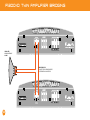
INTRODUCTION
Thank you for purchasing this Cadence Flash Series amplifier. Over the years, the technology used to create audio amplifiers
has grown by leaps and bounds. We have tens of thousands of satisfied customers still using our first generation Ultra
Drive amplifiers which are more than 16 years old. Our competition is satisfied with just continuing to build the same units
year after year without thought for improvement, but not Cadence. We consider it our mission to use our expertise in
developing the latest technologies and to bring you the absolute best sounding, most powerful amplifiers on the market and
of course at a reasonable price. We are very proud to introduce this fifth generation of amplifiers, the Flash Series featuring
C-FORCE technology, “ARVA” and “ADR” circuitry. You will be amazed at the quality and power that these new amps offer.
You will “Boom-Harder!” with Flash Series amplifiers.
We have spared no expense in designing these amplifiers, creating the most rugged, reliable, powerful and best performing
amplifiers. In fact we are so sure of the quality we backup every Flash Series amplifier with our exclusive two-year warranty which
exemplifies our commitment to excellence in car audio musical reproduction. (See enclosed warranty card for details.)
Please read this installation guide carefully for proper use of your Cadence power amplifier. Should you need technical assistance
during or after your installation please call our technical-line between 9:30 am and 5:00 PM EST at (732) 370-5400. Read this
entire guide fully before attempting your installation.
WARNING: BE AWARE! Use of this amplifier at extreme high volumes for extended periods of time may cause hearing loss and
or hearing damage. During periods of prolonged high volume levels it is recommended that you use ear safety devices. Playing
Cadence amplifiers at high volume levels while driving will impair your ability to hear necessary traffic sounds. While driving
always keep your sound volume at reasonable levels. We at Cadence want you listening for many years to come.
When installing the amplifier, secure it tightly. An unmounted amplifier in your car can cause serious injury to passengers and
damage to your vehicle if it is set in motion by an abrupt driving maneuver or short stop.
2
FEATURES
GOLD PLATED TERMINALS:
All the terminals on the amplifier are solid brass and gold plated for high conductivity and
minimum impedance loss. The power and ground terminals are extra large and capable of
accepting 4-8 gauge wire. The speaker terminals can accept 14-16 gauge wire. When wiring
the amplifier, be sure to strip just enough wire that fits into the terminal so that bare wires
do not touch each other, or the amplifier chassis and cause a short circuit. We recommend
using Cadence brand lug and spade connectors for optimum signal transfer. POWER AND PROTECTION CIRCUITRY:
Flash Series amplifiers feature our unique IC controlled protection circuitry. This
sophisticated circuit constantly monitors the heat sink internal temperature and various
voltages, adjusting the amp automatically and protecting it from dangerous conditions.
The 2 LED’s located on the side of the amplifier provide indication of the amplifier status,
the Power LED will light when the amplifier is receiving proper power, ground and remote
voltages and the IC monitoring sequence indicates the amp is functional. In case the
amplifier encounters a diagnostic condition as listed below, the second LED will light
indicating a Diagnostic condition. When a diagnostic condition is sensed the amplifier will
then turn into a self preservation mode and if the cause of the diagnostic condition is not
corrected will eventually shut down. There are certain critical diagnostic conditions which
will turn the amplifier off immediately.
1. Speaker short circuit.
2. Input Overload.
3. Thermal overload.
4. Reverse Polarity.
To reset the amplifier, you must first diagnose what caused the problem, correct the fault and restart
the system. See the Trouble Shooting page for further details.
MUTE CIRCUIT:
The Flash Series amplifiers feature an anti-thump, mute and delay circuit. This eliminates
irritating speaker damaging turn-on and turn-off transients normally experienced with less
expensive amplifiers.
BASS DRIVE EQUALIZATION CIRCUITRY:
A narrow “Q” shelving equalization circuit is included in the amplifiers. The equalization
system is preset at 45Hz. The boost control allows you to add up to 12dB of Bass Drive
effect. Utilize the Bass Drive to tailor your bass response to your systems needs. Please keep
in mind that by adding Bass Drive you are adding stress on your speakers. Make sure your
speakers can handle the extra power output! It would be foolish to add 12dB of gain to low
excursion 8” and 10” Sub woofers or mid ranges and tweeters. It’s a sure way to blow your
speakers. The Bass Drive was designed for High Power sub woofers.
“ADR”: - ACTIVE DYNAMIC REGULATION
Cadence Flash Series amplifiers feature our proprietary ADR, Active Dynamic Regulated
power supplies. 100% HexFET devices are utilized in the power supply for high speed
(100KHz) switching frequencies. The power supplies are capable of supplying the main
amplifier with a considerable amount of reserve voltage for peak “high demand” situations.
The ADR circuit provides full bandwidth power for authoritative bass response, high current
output into low impedance loads and increased headroom. The ADR is supplied with power
via a high speed, high temperature capacitance bank and 100% pure copper rails on the
PCB enabling fast transient response to musical demands.
SUPER CLASS AB AUDIO STAGE PERFORMANCE
The audio output section of the Flash Series amplifiers feature Japanese studio grade,
high current Bi-Polar audio transistors. Unlike other manufacturers who use a host of
different type of transistors, not originally designed for audio output, i.e.: power supply
transistors, motor control transistors to produce the audio signal, (You can only imagine
what they sound like.) Cadence uses only true audio transistors in the audio section of
these amplifiers. These transistors were designed and engineered to produce music. That’s
why Cadence amplifiers clearly sound better. They are cleaner with lower distortion, higher
current capable and more reliable. We challenge you to test listen a Cadence amplifier and
hear the difference yourself.
3
FEATURES
“ARVA”- AUTOMATIC RAIL VOLTAGE ADJUSTMENT CIRCUITRY:
Cadence Flash Series amplifiers feature “ARVA” circuitry in their power supply. This circuit constantly
monitors the output stage and under high current demands will adjust the power supply rail voltages
so that enough power is available for peak situations. The “ARVA” also improves the damping factor of
the amplifier when playing low impedance mono loads. Cadence Flash Series amplifiers have tighter
sounding bass reproduction thanks to
this unique circuitry.
BATTERY VOLTAGE:
Cadence Flash Series amplifiers are rated and regulated to 13.8 volts and below. Increasing voltage to 14.4
volts will increase the power output of the amplifier in the same proportion. Maximum input voltage is
14.4 volts while the minimum voltage is 12 volts.
*** DO NOT EXCEED 14.4 INPUT VOLTAGE. ***
Though capable of high power reproduction, Cadence Flash Series amplifiers are not competition style
amplifiers! They were designed for audiophile sound reproduction.
PROTECTION CIRCUITRY:
Cadence amplifiers incorporate many outstanding protection circuits to help protect the amplifier from
being damaged during operating conditions. Thermal Protection: When the amplifier reaches an unsafe operating temperature of 80 degrees Celsius
the amplifier will turn off. Once the amplifier cools down, simply reset the amplifier by its Remote
connection, (turn the amplifier off and then on again once you have given the amplifier a chance to cool
down) and the amp will once again begin to play.
If you live in a hot climate we suggest installing additional cooling fans in your trunk
to exhaust the hot air which can build up in the trunk this will help keep the ambient
temperature in the trunk as low as possible so that your amps work flawlessly and without any
musical interruption.
Speaker Short Circuit Protection: Should your speakers short circuit due to voice coil burn out, or should the
amplifier sense an impedance too low to handle, the Protection LED will light, indicating a diagnostic condition.
Turn off your system, disconnect one speaker at a time and try to determine which speaker might be faulty.
Correct the condition and restart the amplifier. You must reset the amplifier by turning it OFF and then ON again
by the Remote power connection after correcting a diagnostic condition. (Turn your radio off and then on again.)
Clipping or total shutdown may also be a result of a bad ground connection or loose
ground. If you find that your speakers and speaker wires are not shorted, please check
your ground connection.
Input Overload Protection: This circuit will either shutdown the amplifier completely or
make the amplifier spurt on and off indicating that it is in a diagnostic condition. Turn the
system off and reduce the gain on the amplifier or volume from your head unit, this should
result in a corrected condition.
DC Offset Protection: Should any DC voltage try to enter the amplifier via the speaker
terminals it will cause the amplifier to shut down and not operate until this condition
is remedied. This circuit will also protect damaging high DC voltages from reaching your
speakers should your amplifier ever malfunction.
INSTALLATION BASICS:
Before you begin with your installation, disconnect the NEGATIVE (-) terminal from your car’s
battery. This safety precaution will avoid possible short circuits while wiring your amplifier.
Cadence amplifiers operate on 12-volt negative ground systems only.
It is recommend that you layout your sound system design on paper first. This will help
you during the installation so that you will have a wiring flow chart and not miss-wire any
of your components.
Mount the amplifier in the trunk or hatch area of your vehicle. Never install an amplifier in
the engine compartment or on the firewall. Please be sure to leave breathing room around
the amplifier heat sink so that it can dissipate the heat it produces efficiently. The amplifier
can be installed either horizontally or vertically.
When mounting the amplifier on the trunk floor, be sure to watch for your gas tank, gas
lines and electrical lines. Do not drill or mount any screws where they might penetrate the
gas tank of your car.
INSTALLATION BASICS
REMOTE TURN ON CONNECTION:
The remote turn on connection is located on the barrier strip next to the power and ground
connections. This connection is responsible for turning the amplifier on and off with the rest of the
system. A smaller gauge wire can be used to make this connection to your radio’s power antenna
lead. Should your system not have any turn on leads, you can wire the remote terminal to an
accessory lead, which turns on, with your cars ignition.
POWER/GROUND WIRING:
The Flash Series amplifiers are supplied with built-in fuses, never replace the fuse that the amp came
with, with one of a larger value.
We suggest you construct a Red wiring harness with 2 additional fuses. One fuse should be located
near the car battery. This fuse near the battery offers protection against damage from short circuits
to the car chassis between the battery and the amplifier. A second fuse closer to the amplifier offers
additional safety to the amplifier itself. This fused red power wire should be attached to the amplifier
power terminal marked 12V+.
The wire harness should be made of red primary cable of at least 8 gauge for the F200-2 and at
least 4 gauge for all other larger models. The harness should terminate in a large ring terminal for
connection directly to the positive terminal of the car battery. Use a spade plug to attach the wire,
which connects to the amplifier location marked 12V+.
A second black color wire of equal gauge should be used as a ground connection to a welded chassis
member. When connecting the ground wire make sure that there is no paint or other insulator
blocking a good ground connection. When installing multiple amplifiers, mount them in close
proximity so that they can all share the same ground point. Attach the black ground wire to the
amplifier screw terminal marked Ground.
We recommend that you use the Cadence AMPKIT4 or AMPKIT8 amplifier installation kits, which
contains all the cabling and accessories necessary for a good, reliable installation.
Over the years we have received amplifiers back to our service department with melted power/
ground terminals. The cause of this is a bad ground connection. When there is a lack of good ground,
heat builds up at the weakest point which happens to be the contact screw of the amplifier terminal.
Over time the heat generated will begin to melt the terminal. It is a good practice to feel the power
and ground wires with your hands, near their amplifier connection after having played the amp for
a while. If the wires feel hot to the touch you probably have a bad or loose connection. If you are sure
of your connections and the wires still feel hot to the touch, you should upgrade the gauge of wire
to next heaviest gauge.
SETTING THE CONTROLS:
AUDIO PREAMP INPUT
The Flash Series amplifiers feature RCA pre amp inputs. Run RCA cables from your sound
source to the inputs of the amplifier. We suggest the use of high quality shielded RCA patch
cords to help reduce and eliminate unwanted electrical noise to your system.
Be sure to run the RCA cables on the opposite side of the vehicle that you used to carry the
power and ground leads of the amplifier.
USING THE BUILT-IN LOW PASS ELECTRONIC CROSSOVER
All the Flash Series amplifiers feature 12dB per octave fully adjustable low-pass and high
pass electronic crossovers.
For Low Pass sub woofer systems, set the CROSSOVER MODE switch to LOW PASS. Now
the knob marked FREQUENCY will control the low pass frequencies from 30Hz to 250Hz.
A frequent error made is setting the low pass frequency too low, especially when using
vented sub woofer enclosures. We recommend that for most installations you do not set the
frequency knob lower than 80 - 100Hz (the 12 o’clock position).
When using the amplifiers for component speakers or co-axials, you will want to set the
CROSSOVER MODE switch to HIGH PASS. The FREQUENCY control knob adjusts the high
pass frequencies between 30Hz and 300Hz. Do not attach tweeters directly to the amplifier,
(even in the high pass mode) without a secondary passive crossover to protect them. 250Hz
high pass is not a frequency high enough for tweeters.
SUBSONIC FILTERING
For sub woofer installations with a passive LP crossover, you can set the amplifier’s
CROSSOVER MODE selector to HIGH PASS while setting the FREQUENCY KNOB to 30Hz, this
will act as SUBSONIC FILTER for all signals below 30Hz. This is especially useful for vented
enclosures where the port tuning frequency falls below the sub woofer tuning frequency to
protect against sub woofer unloading.
5
INSTALLATION BASICS
ADJUSTING THE SYSTEM
Once the system is operational, the first thing to do, is set all crossover points to approximate
settings. In the case of the basic sub woofer system Low Pass filter crossover at 100 Hz or so. Set the
Bass Boost equalizer controls to 0 dB ( Flat Switch Position.)
USING THE ELECTRONIC CROSSOVER - 4 CHANNEL MODEL
The four channel models feature separate crossovers for channels 1-2 and 3-4. All the
Flash Series amplifiers feature 12dB per octave fully adjustable low-pass and high pass
electronic crossovers. Mono Block bass amps feature 24dB crossovers.
Now you should set the amplifiers Input Sensitivity adjustment. The knob accessible on the side of
the amplifier marked INPUT GAIN adjusts the input sensitivity from 150mV to 5Volts.
FOUR CHANNEL AMPLIFIER CONFIGURATIONS.
1. All four channels High Pass for internal component speakers in doors and rear decks.
To adjust the input sensitivity, turn the control using a small flat head screwdriver fully counter clock
wise to the minimum position. Do not apply any pressure while turning as this might break the
control unit. Adjust your radio volume level to maximum volume. Now turn the level control on the
amplifier clockwise towards the Maximum marking until audible distortion occurs. When you begin
to hear any distortion in the sound, back down one notch and your amp is set. It is helpful to have a
second person to help you set the gain.
2. Channels 1 and 2 High Pass for front component speakers, while channels 3 and 4 are
wired to sub woofers.
When setting up a multi-amp system, set each amplifier’s gain separately. Start off with the bass
amplifier, then adjust the highs amplifier’s level control to match.
Once you are satisfied with the level control settings, use any equalizer controls to adjust the system
tonal level for personal preference. Keep in mind that after equalizing, you may have to go back and
reset the amplifiers level controls.
*** The level control of any car amplifier should not be mistaken for a volume control. It is a
sophisticated device designed to match the output level of your source unit to the input level of the
amplifier. Do not adjust the amplifier gain to maximum unless your input level requires it.
If your unit has been professionally installed please do not change the gain settings set by the
installer, he is the professional!
Your system can also be extremely sensitive to noise when the LEVEL is set to maximum and does
not match your input signal. The gain adjustments need to be made only once when first setting
up the system.
6
3. Bridge channels 1 and 2 for single high power sub woofer channel. Bridge channels
3 and 4 for second high power sub woofer channel.
For Low Pass systems, set the CROSSOVER MODE switch to LOW PASS. Now the knob
marked FREQUENCY will control the low pass frequencies from 30Hz to 250Hz. A
frequent mistake made is setting the low pass frequency too low, especially when using
vented sub woofer enclosures. We recommend that for most installations you do not set
the frequency knob lower than 100Hz (the 12 o’clock position).
When using the amplifiers for component speakers or coaxial, you will want to set the
CROSSOVER MODE switch to HIGHt PASS. The FREQUENCY control knob adjusts the
high pass frequencies between 30Hz and 250Hz. Do not attach tweeters directly to the
amplifier even in the high pass mode without a secondary passive crossover to protect
them. 250Hz high pass is not a frequency high enough for tweeters.
SUBSONIC FILTERING
For sub woofer installations with a passive LP crossover, you can set the amplifier’s
CROSSOVER MODE selector to HIGH PASS while setting the FREQUENCY KNOB to 30Hz,
this will act as SUBSONIC FILTER for all signals below 30Hz. This is especially useful for
vented enclosures where the port tuning frequency falls below the sub woofer tuning
frequency to protect against sub woofer unloading.
MOUNTING AND WIRING
MOUNTING THE AMPLIFIERS:
Choose a convenient mounting location with unobstructed airflow.
The Flash amplifiers feature four mounting tabs located at the amplifiers four corners.
Using the supplied screws and grommets, gently mount the amplifier in to position.
*** Do not over tighten the screws.***
The Flash Series amplifiers are supplied with built-in fuses, never replace the fuse that the amp
came with, with one of a larger value.
We suggest you construct a Red wiring harness with 2 additional fuses. One fuse should be
located near the car battery. This fuse near the battery offers protection against damage from
short circuits to the car chassis between the battery and the amplifier. A second fuse closer to
the amplifier offers additional safety to the amplifier itself. This fused red power wire should be
attached to the amplifier power terminal marked 12V+.
The wire harness should be made of red primary cable of at least 8 gauge for the F200-2 and at
least 4 gauge for all other larger models. The harness should terminate in a large ring terminal for
connection directly to the positive terminal of the car battery. Use a spade plug to attach the wire,
which connects to the amplifier location marked 12V+.
A second black color wire of equal gauge should be used as a ground connection to a welded
chassis member. When connecting the ground wire make sure that there is no paint or other
insulator blocking a good ground connection. When installing multiple amplifiers, mount them
in close proximity so that they can all share the same ground point. Attach the black ground wire
to the amplifier screw terminal marked Ground.
We recommend that you use the Cadence AMPKIT4 or AMPKIT8 amplifier installation kits, which
contains all the cabling and accessories necessary for a good, reliable installation.
GROUND POINT
FUSE
BATTERY
REMOTE TURN-ON
terminal of head unit
7
OEM RADIO INTEGRATION WITH AUTOSTART
This newest series of Flash amplifiers features our newest
circuitry innovation. Say for example you are trying to
integrate the Cadence Flash amplifier in to a system with an
OEM radio which does not have RCA output jacks or a remote
turn on wire for the amplifier, until now you would have had to
configure a complicated relay system to turn on the amplifier
and use en external high-low converter to send the signal
in to the amplifier.
L
GND
R
But now all you need to do is to wire your speakers to
the included High Level Input harness and plug the
harness in to the amplifier. When you turn on your OEM
head unit, the amplifier will receive the music signal and
automatically turn on the amplifier. When you turn off the
head unit, the amplifier will automatically turn off after a
60 second built-in delay.
Do not use RCA and High Level Input at the same time.
REAR SPEAKER
OUTPUT
Do not keep the speakers hooked up to the High Level Input
once you are using them as the amplifiers signal input.
The ideal ground point for the High Level Input harness is
the radio ground, if thats not possible to reach any good
chassis ground point will do.
8
REMOTE HOOK-UP OPTIONAL
WHEN USING HIGH LEVEL INPUT
GROUND POINT
2 CHANNEL AMP WIRING
All Cadence Flash two channel amplifiers
can accommodate either 2 ohms or 4
ohms per channel in stereo, or one 4
ohm bridged subwoofer. The diagram on
this page shows a basic 2 speaker set up,
for example two 6” x 9” or 6.5” speakers
operating in Full Range.
Adjust Input level and Bass Drive as per
page 6 - Adjusting the System.
LEFT SPEAKER
2-4 OHM
RIGHT SPEAKER
2-4 OHM
2 OHM MINIMUM
PER CHANNEL STEREO
CROSSOVER SWITCH SETTING
CROSSOVER MODE SWITCH IN
FULL RANGE POSITION
9
3 CHANNEL MIXED MONO
CROSSOVER SWITCH SETTING
Here is how to get a three channel system out of a
two channel amplifier.
Crossover mode switch in Full Range.
CROSSOVER MODE SWITCH IN
FULL RANGE POSITION
Hook up Left and Right Speakers normally as per
diagram using high pass filter capacitors. Wire one
subwoofer to the bridged channel utilizing a low pass
filter inductor. You must use this capacitor and inductor
system when using 4 ohm speakers and woofers.
You can eliminate the need for the capacitors
and inductor if you use 4 ohm speakers for the
Left and Right Channel and an 8 ohm woofer for
the bridged channel.
COMPONENT VALUES FOR
6dB PASSIVE CROSSOVER
FREQUENCY
INDUCTOR
CAPACITOR
80 Hz
100 Hz
120 Hz
150 Hz
7.5 mH
6.5 mH
5.5 mH
4 mH
470 uF
330 uF
330 uF
220 uF
LEFT SPEAKER
4 OHM
RIGHT SPEAKER
4 OHM
HIGH PASS
FILTER CAPACITORS
SUBWOOFER
MINIMUM IMPEDANCE
4-8 OHMS
LOW PASS
FILTER INDUCTOR
10
2 CHANNEL AMP BRIDGED MONO
REMOTE SUBWOOFER
LEVEL CONTROL
CROSSOVER SWITCH SETTING
CROSSOVER MODE SWITCH IN
LOW PASS POSITION
When bridging Cadence two channel
amplifiers, the lowest impedance for the
bridged channel is 4 ohms. Set the crossover
switch to Low Pass and Crossover Frequency
Setting to 100 Hz as a beginning point for
tuning your system. Dial in as much Bass
Drive as necessary keeping in mind that
too much Bass Drive can add unnecessary
distortion to your system.
Utilize the Remote Subwoofer Level control
for bass control from the comfort of your
vehicles interior. You must use the cable
that was supplied with the amplifier for the
remote control. Use of standard phone cables
can short out the amplifier.
If you misplace your cable, please contact us
at 800.477.2328 to procure a replacement or
contact your local Cadence dealer.
SUBWOOFER
MINIMUM IMPEDANCE
4 OHMS
11
4 CHANNEL AMP WITH 2 CHANNEL INPUT
If your head unit has only one pair of Left and Right
RCA out put jacks, plug them in to RCA input Jacks
1 and 2 of the amplifier and set the Input model
switch to the 2CH position.
The amplifier preamp circuit will automatically mix
the signals to channels 3 and 4 thereby preserving
your Left and Right Balance control but with no
Fade control Front to Rear.
L
INPUT MODE
SWITCH SETTING
R
TO AUDIO OUTPUTS OF HEAD UNIT OR
SIGNAL PROCESSOR WITH STEREO OUTPUTS
SWITCH IN
2CH POSITION
12
FUSE
BATTERY
REMOTE TURN-ON
terminal of head unit
4 CHANNEL AMPLIFIER WITH 4 CHANNEL INPUT
If your head unit has 2 pairs of RCA output jacks, input Front Left and
Front Right in to Channels 1 and 2. Then attach radio output Rear Left
and Rear Right to Channels 3 and 4. Set the Input Mode Switch to
4Ch position. The pre amp circuitry will not mix any signals thereby
preserving full Left to Right Balance and Front to Rear fader control.
Should your head unit have an additional subwoofer RCA output, that
typically needs to be attached to a separate subwoofer amplifier.
When configuring a 4 channel amplifier to a 3 channel system, you
can use an RCA Y adaptor to send the subwoofer preamp signal
to channels 3 and 4 and bridge those channels to the subwoofer.
Use Y adaptors to mix channels 1 and 3 and input them in to
RCA Channel 1, then mix channels 2 and 4 and input them in to
RCA Channel 2. The result will be preserved Left and Right balance
with constant subwoofer output.
CH3
TO AUDIO OUTPUTS OF HEAD UNIT
OR SIGNAL PROCESSOR WITH
FOUR CHANNEL OUTPUT
CH1
INPUT MODE
SWITCH SETTING
CH2
SWITCH IN
4CH POSITION
CH4
FUSE
BATTERY
REMOTE TURN-ON
terminal of head unit
13
BAsIC FOUR CHANNEL CONFIGURATION
RIGHT SPEAKER
2-4 OHM
CROSSOVER MODES SWITCH IN
FULL RANGE POSITION
FRONT SPEAKERS
LEFT SPEAKER
2-4 OHM
Install any combination of speakers independently
on all 4 channels being careful not to load any single
channel below 2 ohm stereo. For typical 6” x 9” or
6.5” or component speaker installs, set the Crossover
Mode Switch to Full Range.
14
RIGHT SPEAKER
2-4 OHM
REAR SPEAKERS
LEFT SPEAKER
2-4 OHM
4 CHANNEL AMPLIFER BRIDGED TO 2 CHANNELS
When bridging the four channel amplifier, make sure that your final woofer impedance on each bridged channel is no lower than 4 ohms. Set the Crossover Mode Switch to
Low Pass and begin by setting the crossover frequency control to 100Hz and tuning from there. The dashboard bass remote control works only on channels set to Low Pass.
CH 1-2
CROSSOVER MODE SWITCH
IN LOW PASS POSITION
REMOTE SUBWOOFER
LEVEL CONTROL
CH 3-4
CROSSOVER MODE SWITCH
IN LOW PASS POSITION
LEFT SUBWOOFER
MINIMUM IMPEDANCE
4 OHMS
RIGHT SUBWOOFER
MINIMUM IMPEDANCE
4 OHMS
15
4 CHANNEL AMPLIFIER IN 3 CHANNEL MODE
CH 1-2
CROSSOVER MODE SWITCH
IN HIGH PASS POSITION
REMOTE SUBWOOFER
LEVEL CONTROL
Channels 1 and 2 should be wired
to speakers no lower than 2 ohm
loads per channel in stereo. Channel
3 and 4 should be bridged as per the
diagram wiring the woofer to Channel
3 positive side (+) and Channel
4 negative side ( – ) terminals.
CH 3-4
CROSSOVER MODE SWITCH
IN LOW PASS POSITION
CHANNEL 3-4 CONTROL ONLY
Set the crossover mode switch
of Channels 1 and 2 to either Full
Range or High Pass, while Channels
3 and 4 should be set to Low Pass.
Remember that the Dashboard
Bass Remote Control works only on
Low Pass Channels.
Please see page 13 for RCA input
configuration details and instructions
when wiring a 3 channel system.
16
LEFT
SPEAKER
RIGHT
SPEAKER
2-4 OHMS
2-4 OHMS
SUBWOOFER
MINIMUM IMPEDANCE
4 OHMS
4 CHANNEL WITH MIXED MONO
REMOTE SUBWOOFER
LEVEL CONTROL
SUBWOOFER
MINIMUM IMPEDANCE
4 OHMS
CH 1-2 CROSSOVER MODE SWITCH
IN FULL RANGE POSITION
CHANNEL 3-4 CONTROL ONLY
CH 3-4 CROSSOVER MODE SWITCH
IN LOW PASS POSITION
LEFT SPEAKER
FRONT SPEAKERS
RIGHT SPEAKER
MINIMUM SPEAKER IMPEDANCE 4 OHMS
SUBWOOFER
MINIMUM IMPEDANCE
8 OHMS
LOW PASS
FILTER INDUCTOR
17
4 CHANNEL WITH DUAL MIXED MONO CONFIGURATION
LOW PASS
FILTER INDUCTOR
REAR SPEAKERS
ALL CROSSOVER
SETTINGS IN THIS
MODE SHOULD BE
FULL RANGE.
SUBWOOFER
MINIMUM IMPEDANCE
8 OHMS
HIGH PASS
FILTER CAPACITORS
LEFT SPEAKER
4 OHM
RIGHT SPEAKER
4 OHM
COMPONENT VALUES FOR
6dB PASSIVE CROSSOVER
LEFT SPEAKER
FRONT SPEAKERS
RIGHT SPEAKER
MINIMUM SPEAKER IMPEDANCE 4 OHMS
SUBWOOFER
MINIMUM IMPEDANCE
4-8 OHMS
LOW PASS
FILTER INDUCTOR
18
FREQUENCY
INDUCTOR
CAPACITOR
80 Hz
100 Hz
120 Hz
150 Hz
7.5 mH
6.5 mH
5.5 mH
4 mH
470 uF
330 uF
330 uF
220 uF
FIVE CHANNEL INPUT MODE
If your head unit has one single pair of RCA
outputs, input them in to the amplifiers Channel
1 and 2 input jacks and set the Input Mode Switch
to 2Ch. The amplifiers preamp circuitry will
automatically mix all the channels and output will
occur on all 5 channels. There will be Left and Right
balance with constant subwoofer but no Front to
Read Fader Control.
2 CHANNEL MODE
If your head unit has two pairs of RCA outputs,
input Front Left and Front Right in to amplifier
Channels 1 and 2 input jacks. Rear Left and Rear
Right in to amplifiers Channels 3 and 4 input jacks.
Set the Input Mode Switch to 4Ch. The amplifiers
preamp circuitry will automatically mix all the
channels and output will occur on all 5 channels.
There will be Left and Right balance, Front to Rear
Fader with constant subwoofer.
4 CHANNEL MODE
If your head unit has three pairs of RCA outputs,
input Front Left and Front Right in to amplifier
Channels 1 and 2 input jacks. Rear Left and Rear
Right in to amplifiers Channels 3 and 4 input jacks.
Subwoofer output in to Channel 5. If your head
unit has only a single subwoofer output, use a Y
adaptor to feed both Channel 5 inputs. Set the
Input Mode Switch to 5Ch. The amplifiers preamp
circuitry will automatically mix all the channels
and output will occur on all 5 channels. There will
be Left and Right balance, Front to Rear Fader with
independent subwoofer.
5 CHANNEL MODE
INPUT MODE
SWITCH SET TO 2CH
INPUT MODE
SWITCH SET TO 4CH
INPUT MODE
SWITCH SET TO 5CH
19
5 CHANNEL AMPLIFIER SPEAKER WIRING
Minimum impedance for channels 1 through
4 is 2 ohm stereo. Channel five minimum
impedance is 2 ohm mono capable.
COMPONENT SPEAKERS
MINIMUM IMPEDANCE
2-4 OHMS
INPUT MODE
SWITCH SET TO 5CH
COMPONENT SPEAKERS
MINIMUM IMPEDANCE
2-4 OHMS
20
SUBWOOFER
MINIMUM IMPEDANCE
2-4 OHMS
MONO BLOCK 2 OHM AMPLIFIERS
Models:
F500-1 /
F700-1
2 OHM MINIMUM LOAD
4 OHM SUBWOOFER
4 OHM SUBWOOFER
- OR DVC 4 OHM SUBWOOFER
IN PARALLEL = 2 OHM LOAD
Both models F500-1 and 700-1 are 2 ohm mono block
amplifiers. No matter how many woofers you choose to
wire up to these models the final impedance should not
fall below 2 ohms. Please see page 28 and 29 for various
speaker impedance configurations.
21
CLASS D MONO BLOCK 1 OHM AMPLIFIER
GND
Model:
F1200-1D
The F1200-1D is a 1 ohm stable mono block amplifier. It features RCA pre amp line output for feeding of a
full range signal to a secondary full range amplifier in a multi-amp system. The F1200-1D also features our
Integrated OEM Auto Start Sensing Circuit when used through the High Level Speaker input. No external
remote trigger wire is required when using the High Level Input to start the amplifier. There is a 60 second
turn off delay when using the High Level Input.
22
F1200-1D SPEAKER CONFIGURATION
1 OHM MINIMUM LOAD
2 OHM SUBWOOFER
Model F1200-1D is a 1 ohm mono block Class D amplifier.
No matter how many woofers you choose to wire up to this
amplifier the final impedance load should not fall below
1 ohm. Please see pages 28 and 29 for various speaker
impedance configurations.
2 OHM SUBWOOFER
- OR DVC 2 OHM SUBWOOFER
IN PARALLEL = 1 OHM LOAD
23
F1200-1d TWIN AMPLFIER BRIDGING
MASTER
GND
SWITCH SET TO MASTER
MASTER / SLAVE LINK
SLAVE
GND
24
SWITCH SET TO SLAVE
REMOTE SUBWOOFER
LEVEL CONTROL
F1200-1d TWIN AMPLFIER BRIDGING
Two F1200-1D can be ridged together for double the power output into a 2-ohm load. Though each amp is 1 ohm stable,
when bridging amplifiers, you must bridge them to a 2 ohm load.
Input the head unit signal into the MASTER amplifier and set the Bridged Mode switch to Master. Use the supplied DATA
CABLE to send the fully processed signal from the MASTER amplifier to the secondary SLAVE amplifier and set the Bridged
Mode switch to Slave. Do not input any high level or RCA signals into the Slave amplifier.
All crossover controls, Bass Drive, frequency settings, and subsonic filter settings will be controlled by the Master Amplifier
including input gain levels. There is no need to gain match the two amplifiers, it will occur automatically. The remote dash
bass control should be plugged in to the Master amplifier and it will control both amplifiers.
Make sure to use the supplied DATA CABLE for linking of the amplifiers and not the dash board bass remote cable or any
other phone jack cable. If you misplace your cable, contact Cadence or your local dealer to procure a new one.
This same input/control system can be utilized when daisy chaining two amplifiers to two independent 1 ohm woofers as
long as you don’t bridge the two amplifiers outputs together.
25
F1200-1d TWIN AMPLFIER BRIDGING
SUBWOOFER
MINIMUM IMPEDANCE
2 OHMS
IMPORTANT NOTE:
CONNECT THE TWO SPEAKER NEGATIVES
TOGETHER WITH A #12 WIRE STRAP.
26
F1200-1d TWIN AMPLFIER BRIDGING
Once again, when bridging two amplifiers together, the final impedance load of the bridged amplifiers should be no lower
than 2-ohms. Double power will occur at 2-ohms.
Master amplifiers positive (+) speaker terminal should be wired to the positive terminal of the subwoofer.
Slave amplifiers positive (+) speaker terminal should be wired to negative terminal of the subwoofer.
Now connect a heavy gauge wire (12 Gauge) between the negative (-) terminal of the Master amplifier and the
Negative (-) terminal of the Slave amplifier.
Please see diagram for a detailed drawing.
When daisy chaining two amplifiers for independent woofers, wire up the the woofers as you would typically wire them
when installing individual systems, even down to 1-ohm. By using the Master/Slave input configuration you gain the
advantage of having one amplifiers’ preamp section control both amplifiers, eliminating the need to gain match and
crossover match your system between amplifiers.
27
SPECIFICATIONS
F500-1
F1200-1D
• Rated Power: 350 Watts RMS @ 4 ohm
• Rated Power: 700 Watts RMS @ 2 ohm
• Rated Power: 500 Watts RMS @ 2 ohm / 1000 Watts Peak Power
• Rated Power: 1200 Watts RMS @ 1 ohm / 2400 Watts Peak Power
• Minimum THD at Rated Power: < 0.05%
• Minimum THD at Rated Power: < 0.05%
• Frequency Response: 10Hz - 40KHz
• Frequency Response: 15 - 150Hz
• S / N Ratio: > 100dB
• S / N Ratio: > 100dB
• Damping Factor: > 200 @ 100Hz
• Damping Factor: > 200 @ 100Hz
• Channel Separation: > 65dB
• Channel Separation: > 65dB
• Dimensions: ( W x H x L ) 11” x 2.75” x 13”
• Dimensions: ( W x H x L ) 11” x 2.75” x 16”
F700-1
F200-2
• Rated Power: 400 Watts RMS @ 4 ohm
• Rated Power: 75 Watts RMS @ 4 ohm
• Rated Power: 800 Watts RMS @ 2 ohm / 1600 Watts Peak Power
• Rated Power: 125 Watts RMS @ 2 ohm
• Minimum THD at Rated Power: < 0.05%
• Bridged Power: 250 Watts @ 4 ohm RMS Mono / 500 Watts Peak Power
• Frequency Response: 10Hz - 40KHz
• Minimum THD at Rated Power: < 0.05%
• S / N Ratio: > 100dB
• Frequency Response: 10Hz - 40KHz
• Damping Factor: > 200 @ 100Hz
• S / N Ratio: > 100dB
• Channel Separation: > 65dB
• Damping Factor: > 200 @ 100Hz
• Dimensions: ( W x H x L ) 11” x 2.75” x 16”
• Channel Separation: > 65dB
• Dimensions: ( W x H x L ) 11” x 2.75” x 9”
28
SPECIFICATIONS
F300-2
F400-4
F800-4HC
• Rated Power: 125 Watts RMS @ 4 ohm
• Rated Power: 75 Watts RMS @ 4 ohm
• Rated Power: 125 Watts RMS @ 4 ohm
• Rated Power: 175 Watts RMS @ 2 ohm
• Rated Power: 125 Watts RMS @ 2 ohm
• Rated Power: 175 Watts RMS @ 2 ohm
• Bridged Power: 350 Watts @ 4 ohm RMS Mono / 700 Watts Peak Power
2 x 250 Watts @ 4 ohm RMS Mono / 1000 Watts Peak Power
• Rated Power: 225 Watts RMS @ 1 ohm
• Minimum THD at Rated Power: < 0.05%
• Minimum THD at Rated Power: < 0.05%
• Frequency Response: 10Hz - 40KHz
• Frequency Response: 10Hz - 40KHz
• Bridged Power: 2 x 450 Watts @ 2 ohm RMS Mono
• S / N Ratio: > 100dB
• S / N Ratio: > 100dB
• Minimum THD at Rated Power: < 0.05%
• Damping Factor: > 200 @ 100Hz
• Damping Factor: > 200 @ 100Hz
• Frequency Response: 10Hz - 40KHz
• Channel Separation: > 65dB
• Channel Separation: > 65dB
• S / N Ratio: > 100dB
• Dimensions: ( W x H x L ) 11” x 2.75” x 11”
• Dimensions: ( W x H x L ) 11” x 2.75” x 13”
• Damping Factor: > 200 @ 100Hz
1800 Watts Peak Power
• Channel Separation: > 65dB
• Dimensions: ( W x H x L ) 11” x 2.75” x 18”
F300-3
F600-4
F100-5
• Rated Power: 100 Watts RMS @ 4 ohm x 2
• Rated Power: 125 Watts RMS @ 4 ohm
• Rated Power: 100 Watts RMS @ 4 ohm x 4
• Rated Power: 150 Watts RMS @ 2 ohm x 2
• Rated Power: 175 Watts RMS @ 2 ohm
• Rated Power: 150 Watts RMS @ 2 ohm x 4
• Channel 3: 300 Watts @ 4 ohm RMS Mono
• Bridged Power: 2 x 350 Watts @ 4 ohm RMS Mono
• Channel 5: 300 Watts @ 4 ohm RMS Mono
500 Watts @ 2 ohm RMS Mono
1800 Watts Peak Power
1400 Watts Peak Power
• Minimum THD at Rated Power: < 0.05%
500 Watts @ 2 ohm RMS Mono
1800 Watts Peak Power
• Minimum THD at Rated Power: < 0.05%
• Frequency Response: 10Hz - 40KHz
• Minimum THD at Rated Power: < 0.05%
• Frequency Response: 10Hz - 40KHz
• S / N Ratio: > 100dB
• Frequency Response: 10Hz - 40KHz
• S / N Ratio: > 100dB
• Damping Factor: > 200 @ 100Hz
• S / N Ratio: > 100dB
• Damping Factor: > 200 @ 100Hz
• Channel Separation: > 65dB
• Damping Factor: > 200 @ 100Hz
• Channel Separation: > 65dB
• Dimensions: ( W x H x L ) 11” x 2.75” x 18
• Channel Separation: > 65dB
• Dimensions: ( W x H x L ) 11” x 2.75” x 18”
• Dimensions: ( W x H x L ) 11” x 2.75” x 18”
29
SPEAKER WIRING CHART
4 X DUAL VC 8 OHM
SPEAKERS WITH
SERIES VOICE COILS, ALL IN
PARALLEL
4+4
OHM
4+4
OHM
4+4
OHM
4+4
OHM
2 OHM
TO
AMPLIFIER
2
OHM
SERIES:
SINGLE VOICE COIL
SPEAKERS
PARALLEL:
SINGLE VOICE COIL
SPEAKERS
4 OHM
TO AMPLIFIER
2
OHM
30
2 OHM
TO AMPLIFIER
4
OHM
4
OHM
SPEAKER WIRING CHART
SERIES:
DUAL VOICE COIL
SPEAKERS
8 OHM
TO AMPLIFIER
PARALLEL:
DUAL VOICE COIL
SPEAKERS
Please note that the minimum impedance load for
single Cadence Flash Amplifiers is 2 ohm stereo
and 4 ohm mono bridged.
4+4
OHM
4+4
OHM
2 OHM
TO AMPLIFIER
Lower impedance loads will cause overheating
and may damage the amplifiers.
Do not mix different impedance speakers in series
and / or parallel combinations, as unequal power
sharing and acoustic outputs will result.
4 OHM
TO AMPLIFIER
2+2
OHM
2 X DUAL VC 2 OHM SPEAKERS WITH
SERIES VOICE COILS, ALL IN PARALLEL
2 OHM
TO AMPLIFIER
2 OHM
TO AMPLIFIER
2+2
OHM
2+2
OHM
1+1
OHM
31
Due to constant product improvements, these specifications are subject to change without notice.
Though we tried our best to insure that this manual is free and clear of errors please don’t hold us responsible for printing errors.
Copyright by Cadence Acoustics LTD.