1
Bulletin HY25-1650-M1/US
Owner’s Manual
Electronic
Overspeed Control
Effective:
April 2010
Supercedes: HY25-1650-M1/US
December 2009
WARNING — User Responsibility
FAILURE OR IMPROPER SELECTION OR IMPROPER USE OF THE PRODUCTS DESCRIBED HEREIN OR
RELATED ITEMS CAN CAUSE DEATH, PERSONAL INJURY AND PROPERTY DAMAGE.
This document and other information from Parker-Hannifin Corporation, its subsidiaries and authorized distributors
provide product or system options for further investigation by users having technical expertise.
The user, through its own analysis and testing, is solely responsible for making the final selection of the system and
components and assuring that all performance, endurance, maintenance, safety and warning requirements of the
application are met. The user must analyze all aspects of the application, follow applicable industry standards, and
follow the information concerning the product in the current product catalog and in any other materials provided from
Parker or its subsidiaries or authorized distributors.
To the extent that Parker or its subsidiaries or authorized distributors provide component or system options based
upon data or specifications provided by the user, the user is responsible for determining that such data and
specifications are suitable and sufficient for all applications and reasonably foreseeable uses of the components
or systems.
Offer of Sale
The items described in this document are hereby offered for sale by Parker Hannifin Corporation, its subsidiaries or its
authorized distributors. This offer and its acceptance are governed by the provisions stated in the “Offer of Sale”.
Patent Information
The Chelsea® Power Take-Off or its components shipped with this owner’s manual may be manufactured under one
or more of the following U.S. patents:
4610175 5228365
4597301 5645363
6151975
6142274
6260682 7159701 B2 7510064
US7690450 B2
Other patents pending.
© Copyright 2010, Parker Hannifin Corporation, All Rights Reserved
II
Parker Hannifin Corporation
Chelsea Products Division
Olive Branch, MS 38654 USA
Bulletin HY25-1650-M1/US
Contents
Owner’s Manual
Electronic Overspeed Control
General Safety Information
Safety Information.............................................................................1
Foreword...........................................................................................2
Installation Instructions
The Control.......................................................................................3
Installation P.T.O. Components.........................................................4
Wiring the Control Unit.....................................................................5
Electronic Overspeed (E.O.C.) Installation Sketch for 270,
271,800 and 852 Series (Allison).....................................................6
Electronic Overspeed (E.O.C.) Installation Sketch for 230
and 231 Series 12 and 24 Volt..........................................................7
Electronic Overspeed (E.O.C.) Installation Sketch for 885 Series
12 and 24 Volt...................................................................................8
Electronic Overspeed (E.O.C.) Installation Sketch for 270 Series
12 and 24 Volt...................................................................................9
Electronic Overspeed (E.O.C.) Installation Sketch for 270
and 271 Series (Allison 1000, 2000/2400).....................................10
Electronic Overspeed (E.O.C.) Installation Sketch for 230
and 231 Series 12 and 24 Volt (Allison 1000, 2000/2400)..............11
Electronic Overspeed (E.O.C.) Installation Sketch for 277, 278
and 859 Series for Allison (SK-472)...............................................12
Electronic Overspeed (E.O.C.) Installation Sketch for 277, 278
and 859 Series for Caterpillar (SK-473).........................................13
Electronic Overspeed (E.O.C.) Installation Sketch for 247 Series..14
247 Series Wiring Chart.................................................................15
Electronic Overspeed (E.O.C.) Installation Sketch for 890 Series..16
Electronic Overspeed (E.O.C.) Installation Sketch for 248 Series..17
248 Series Wiring Chart.................................................................18
Control Adjustment Instructions........................................................19-21
Operating Instructions......................................................................22-23
Troubleshooting.....................................................................................24
P.T.O. Maintenance................................................................................25
Offer of Sale..........................................................................................27
III
Parker Hannifin Corporation
Chelsea Products Division
Olive Branch, MS 38654 USA
IV
Parker Hannifin Corporation
Chelsea Products Division
Olive Branch, MS 38654 USA
Bulletin HY25-1650-M1/US
General Information
Owner’s Manual
Electronic Overspeed Control
Safety Information
These instructions are for your safety and the safety of the end user. Read
them carefully until you understand them.
General Safety Information
WARNING: Before selecting or using this product, it is important that
you read and follow the product warnings and instructions in the Owner’s
Manual.
WARNING: Failure or improper use of the Parker Chelsea Electronic
Overspeed Control, Power Take-Offs (P.T.O.s) or related accessories can
cause death, personal injury and property damage. Possible consequences
of failure or improper use of these products include but are not limited to the
following:
•Operators, bystanders or equipment being crushed, impacted or caused
to fall due to the sudden, inadvertent, unintended, uncontrolled or
unexpected movement, stopping or starting of devices such as lifts,
hoists, blowers, augers or pumps which are driven by a P.T.O. This can
occur when the P.T.O. is improperly or unexpectedly engaged or
disengaged.
•Rotating shaft injuries resulting from skin, hands, clothing, hair or the like
getting caught in the rotating shaft connected to a P.T.O. or the rotating
portion of the equipment driven by the P.T.O.
WARNING: Always remember to disengage the P.T.O. when the driven
equipment is not in operation.
WARNING: When the Parker Chelsea Electronic Overspeed
Control is set up in Auto Re-engagement Mode, the P.T.O. will
automatically engage when the engine RPM reaches the lower preset point
thus causing the driven equipment to become operable. The vehicle or
equipment operator must therefore make certain that other persons and
property are not in a position to be crushed, impacted, caused to fall or
otherwise injured when re-engagement occurs.
WARNING: Original equipment manufacturers incorporating the Parker
Chelsea Electronic Overspeed Control into their equipment must undertake a
failure mode and effect analysis (FMEA) to identify potential hazards created
by the Automatic Re-engagement Mode. They must then incorporate fail safe
designs into their equipment to protect operators, other persons and property
from injury associated with unexpected disengagement or re-engagement of
the P.T.O.
1
Parker Hannifin Corporation
Chelsea Products Division
Olive Branch, MS 38654 USA
Bulletin HY25-1650-M1/US
General Information
Owner’s Manual
Electronic Overspeed Control
Foreword
What It Is
The Chelsea Electronic Overspeed Control (E.O.C.) is an electronic
controller that prevents the Power Take-Off and driven equipment from being
operated at excessive speeds. This is done by automatically disengaging the
Power Take-Off whenever a pre-set overspeed R.P.M. is exceeded.
How It Works
The Chelsea Electronic Overspeed Control (E.O.C.) energizes the solenoid
valve that engages the clutch in the Power Take-Off. The control also
measures the speed of the Power Take-Off and electronically compares it to
the pre-set overspeed R.P.M. setting. As long as the operating speed is less
than the high limit, the Power Take-Off will operate in a normal manner.
If the operating speed exceeds the selected high limit, the control will
automatically de-energize the solenoid valve and the Power Take-Off clutch
will disengage. The clutch will remain disengaged until the speed has been
reduced to the pre-set low limit.
2
Parker Hannifin Corporation
Chelsea Products Division
Olive Branch, MS 38654 USA
Bulletin HY25-1650-M1/US
Installation Instructions
Owner’s Manual
Electronic Overspeed Control
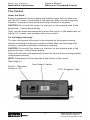
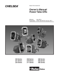
The Control
Under the Dash:
Select a convenient location where the indicator lights will be visible and
the ON-OFF button is accessible to the operator. Mark two mounting hole
locations, using the control panel mounting bracket as a template.
CAUTION: Do not drill into wires or a vital part on the opposite side of the
dashboard – check before drilling.
Then, drill two holes and temporarily mount the control to the dashboard, using the 1/4" screws, lock-washers and nuts provided.
On the Engine Housing:
Tilt cabs may require the control to be mounted on the engine housing,
with the mounting bracket and screws provided. Mark two mounting hole
locations, using the mounting bracket as a template.
CAUTION: Do not drill into wires or a vital part on the opposite side of the
engine housing – check before drilling.
Then drill two holes and temporarily mount the control and mounting bracket
to the engine housing.
NOTE: Adjustments will be required at the bottom of the control.
(See Page 21)
Over Speed = Yellow
On/Off = Red when
System is “On”
P.T.O. Engaged = Red
3
Parker Hannifin Corporation
Chelsea Products Division
Olive Branch, MS 38654 USA
Bulletin HY25-1650-M1/US
Installation Instructions
Owner’s Manual
Electronic Overspeed Control
The Solenoid Valve
Select a convenient location, near the Power Take-Off to allow the use of
shorter hoses, but away from moving parts and the hot exhaust pipe. Mark
the mounting hole locations, using the solenoid valve mounting bracket as a
template.
CAUTION: Do not drill into wires or a vital part on the opposite side of the
mounting surface – check before drilling.
Attach the solenoid valve to the mounting bracket using the screws provided
and mount them to the vehicle.
The Pressure Switch
Install the pressure switch, the screen adapter and the three hoses, as
shown in the SK drawing for your Power Take-Off.
The Speed Pick-up
In case the speed pick-up was not installed at the factory, remove and
discard the plug in the Power Take-Off case over the input gear. Install the
speed pick-up and tighten it with a crowsfoot adapter and a torque wrench
to approximately 24-lb. ft. torque. Proceed with the electrical hook-up of the
control system, as shown in the SK drawing for your Power Take-Off.
Routing the Cables
Tilt Cabs: To permit the cab to tilt, the cables must be routed around the
cab pivot point.
Conventional Cabs: Holes in the firewall are usually provided for the
speedometer cable or wiring harnesses and the control cables can usually
be routed through them.
A Through-Hole: If an existing through-hole cannot be used, drill a 1"
diameter hole and install the split rubber grommet provided, after all the
wires have been installed.
CAUTION: Do not drill into wires or a vital part on the opposite side – check
before drilling.
4
Parker Hannifin Corporation
Chelsea Products Division
Olive Branch, MS 38654 USA
Bulletin HY25-1650-M1/US
Installation Instructions
Owner’s Manual
Electronic Overspeed Control
Wiring the Control Unit
Input Power-the Red Wire: Connect to a source of power that is “switched”
or hot only when the key is in the ON position, using the instant connector
provided. This unit can be wired to 12V or 24V DC supply (Mininum 5 amp).
Input Ground-the Black Wire: Good ground connections are important . . .
directly on the frame is best . . . fiberglass panels won’t work at all.
Wiring the Solenoid Valve
Ground-either Red wire: Attach the ring connector provided and make a
good ground connection, preferably on the truck frame.
Power-the “other” Red wire: Connect the other red wire to the green wire
with the butt connector provided. Route this green wire to the control unit and
connect it to the green wire.
Wiring the Pressure Switch
Ground: Using the black wire provided in the kit, push the bullet connector
end onto either terminal of the pressure switch. Make a good ground connection with the other end of the black wire, on the truck frame. Using the blue
wire provided in the kit, push the bullet connector onto the other terminal of
the pressure switch. Route the wire to the control unit and connect it to the
blue wire.
Wiring the Speed Pick-up
Selecting the Cable: A ten foot long cable is provided in the kit, which
should be adequate for most installations. Additional five or ten foot long
cables are available and can be connected end-to-end if necessary.
Dealing with Cable “Extra” Length: The cables are specially shielded and
must not be cut or spliced. Any extra length should be coiled up and tucked
away under the dash.
Routing & Protecting the Cables: Bundle together the speed pick-up cable,
the pressure switch wire and the solenoid wire. Route the wires away from
moving parts, hot pipes, sharp edges and up out of the way.
5
Parker Hannifin Corporation
Chelsea Products Division
Olive Branch, MS 38654 USA
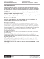
379265
Grommet
16 AWG Wire, Black
Ring Connector
(4.9")
6
Slice Grommet
Insert Wires and
Push into Hole in
Firewall
Drill 1" Hole
in Firewall
Electronic Overspeed
Controller - 329650X
(1.8")
(1.0")
Port B
379243
Speed Sensor
Connector with
2-Wire Cable
14 AWG Wire, Blue
with Butt Connector
14 AWG Wire, Green
with Butt Connector
Port C
271 Series P.T.O.
328923-10X
2-Wire Cable 10 Ft. with
Male and Female Connector
328923-5X Optional 5-Ft.
379254-13
14 AWG Wire, Blue
Bullet Connector
From Trans to Valve
329087X Pressure Lube Hose
379254-3
14 AWG Wire, Green
with Butt Connector
Port A
IN CYL
500457-6
Screw
5000357-7
Washer
.125"-27 NPTF
378966
Street Tee
379547
Pressure Switch
Ground
From Valve to P.T.O.
328075X
Pressure Lube
Hose (2)
Dump Line Back
to Transmission
thru P.T.O.
379193-1 (12 Volt) Green
379686-2 (24 Volt) Black
Solenoid Valve
379254-14
14 AWG Wire, Black
with Ring and
Bullet Connector
379258
Bracket
379449
Screen Adapter
18 AWG Wire, Red
379253 14 AWG Ring Connector
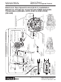
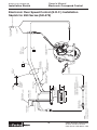
Installation Sketch
NOTE:
1)Strip Wire Ends 0.25" Prior to Installing into Connector
Ground
16 AWG Wire, Red
Connect to 12 VDC or
24 VDC, 5A Minimum
Ignition Circuit
Ground
Bulletin HY25-1650-M1/US
Owner’s Manual
Electronic Overspeed Control
Electronic Over Speed Control (E.O.C.) Installation
Sketch for 270, 271, 800 and 852 Series (Allison) (SK-466)
Parker Hannifin Corporation
Chelsea Products Division
Olive Branch, MS 38654 USA
16 AWG Wire, Black
with Ring Connector
(4.9")
Electronic Overspeed
Controller - 329650X
Slice Grommet
Insert Wires and
Push into Hole in
Firewall
Air Supply
90-140 P.S.I.
7
(1.8")
(1.0")
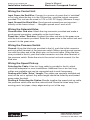
379254-8
14 AWG Wire, Green
with Fork Connector
379044-7
Nylon Tubing
230 Series
328923-10X 2-Wire Shielded
Cable, 10 Ft., with
Male and Female Connectors.
328923-5X Optional 5-Ft.
379254-13
14 AWG Wire, Blue
Bullet Connector
379917
Speed Sensor
2-Wire Shielded
Cable with
Connector
16 AWG Wire, Blue
with Butt Connector
16 AWG Wire, Green
with Butt Connector
Note Direction
of Arrows
379042
Connector
378414 Pressure
Protection Valve
379131-1
Reducer
379043
Elbow
379042
Connector
378966
Street Tee
379547
Pressure Switch
379254-14
14 AWG Wire, Black
with Ring and
Bullet Connector
379106
Breather
379044-7
Plastic Tubing
500456-6
Screw
500357-7
Washer
379043
Elbow
379258
Bracket
379303-1 Valve - 12 Volt
379303-2 Valve - 24 Volt
379305
Pressure Switch
Ground
378966
Street Tee
379253 Ring
Connector
379306
Fork Connector
Ground
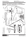
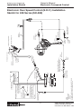
Installation Sketch
NOTE: Strip Wire Ends 0.25" Prior to Installing Connector
Ground
16 AWG Wire, Red
Connect to 12 VDC or
24 VDC, 5A Minimum
Ignition Circuit
379265
Grommet
Drill 1" Hole
in Firewall
378416
Hex Nipple
Bulletin HY25-1650-M1/US
Owner’s Manual
Electronic Overspeed Control
Electronic Over Speed Control (E.O.C.) Installation
Sketch for 230 and 231 Series 12 and 24 Volt (SK-467)
Parker Hannifin Corporation
Chelsea Products Division
Olive Branch, MS 38654 USA
Note Direction
of Arrows
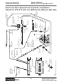
8
379306 Spade Terminal
IN
500357-7 Washer
500457-6 Screw
379258 Bracket
CYL
379043 Elbow
379106 Breather
379253 Ring Connector
Connect to Ground
(4.9")
(1.8")
Electronic Overspeed
Controller - 329650X
(1.0")
379044-7 Plastic Tubing
379042 Connector
379254-8
14 AWG Wire, Green
R
UP
CHELSEA
885 Series P.T.O.
SEA
CHEL
378966 Street Tee
379547 Pressure Switch
379253 Ring Connector
379254-14
14 AWG Wire, Black
379253 Ring Connector
Connect To Ground
379254-13
14 AWG Wire, Blue
Run Wires Through
Grommet In Firewall
16 AWG Green Wire
16 AWG Blue Wire
Speed Sensor Extension Cable
328923-10X (10 Ft Supplied w/E.O.C.)
328923-5X (5 Ft Optional Cable)
379306 Spade Terminal
379305 Pressure Switch
379043 Elbow
379303-1 Solenoid 12V
379303-2 Solenoid 24V
378966 Street
Tee
379042 Connector
379044-7 Plastic Tubing
16 AWG Wire, Black
Connect to Ground
16 AWG Wire, Red
Connect to 12 VDC or
24 VDC, 5A Minimum
Ignition Circuit
379265
Grommet
28-P-171 O-Ring
379243 Speed Sensor
Run Wires Through
Grommet in Firewall
Slice Grommet
Insert in Hole
in Firewall
1.00" Hole
in Firewall
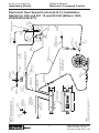
Installation Sketch
NOTE:
1)Strip Wire Ends .25" Prior to Installing in Connectors
Air Supply
90-140 PSI
378416 Hex
Nipple
378414 Pressure
Protection Valve
Reference Kits:
328388-52X = Air Shift 12 VDC with E.O.C.
328388-53X = Air Shift 24 VDC with E.O.C.
Bulletin HY25-1650-M1/US
Owner’s Manual
Electronic Overspeed Control
Electronic Over Speed Control (E.O.C.) Installation
Sketch for 885 Series 12 and 24 Volt (SK-468)
Parker Hannifin Corporation
Chelsea Products Division
Olive Branch, MS 38654 USA
379449
Screened
Adapter
9
(4.9")
Electronic Overspeed
Controller - 329650X
(1.8")
(1.0")
16 AWG Wire, Blue
with Butt Connector
16 AWG Wire, Green
with Butt Connector
NOTES:
1)For Installation Parts Refer to Kits:
328929-12X & -24X = Installation Kit
329049X = Special Fitting Kit
2)Direction of Oil Flow
3)Strip Wire Ends 0.25" Prior to Installing Connector
16 AWG Wire, Black
with Ring Connector
.250"- 18 NPTF
Port C
378966
Street Tee
Screened
▼
P.T.O. Mounting Surface S.A.E. 6 Bolt
P.T.O. Opening Remove Cover on
Transmission Before Installing P.T.O.
Lube Pressure
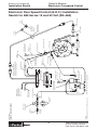
Top View
High Pressure Port
379749
Male Connector
329130-5X
High Pressure
Hose Ass'y
.125"- 27 NPTF
Port B
379243 Speed Sensor Locate over
Gear Teeth
NOTE: Insert Hose Fittings at Plastic Plug
Locations (Remove & Discard Plugs)
Chelsea Power-Take-Off
Model: 270 Series/Rear View of P.T.O.
Drill 1" Hole
in Firewall for 379265 Grommet
379254-14
14 AWG Wire, Black
with 2-Ring Connectors
379265 Grommet
- Slice Grommet
- Insert Wires
- Push into Hole thru Firewall
Ground
379547
Pressure
Switch
379254-13
379280
16 AWG Wire,
Flare Fitting Blue with
500357-1 (2) Ring Connector
Lock Washer
379258
500457-6 (2)
Mounting Bracket Mounting Screw
IN CYL
EXH
.125"-27 NPTF
Port A
On Closed
Bearing Cap
329087X
Pressure Hose
379686-1 12 Volt (Green)
379686-2 24 Volt (Black)
379280
Flare Fitting
FROM VALVE (EXHAUST) -TO- P.T.O. (DUMP PORT-B)
FROM TRANSMISSION (HIGH PRESSURE) -TO- VALVE (INLET)
OPTIONAL: 328923-5X CABLE (5 FT.)
MUST BE ORDERED SEPERATE BY CUSTOMER
▼
Line Pressure
Left View
Electronic Over Speed Control (E.O.C.) Installation
Sketch for 270 Series 12 and 24 Volt AISIN Automatic
Transmission (Models A443, A445 & A450-43LE)
(SK-469)
379749
Male Connector
Low Pressure Port
Aisin Automatic Transmission
Rear View
329087X Pressure Lube Hose Connect to
Low Pressure Port on Transmission and to
P.T.O. Idler Shaft Lube Port “C”
Installation Sketch
Ground
16 AWG Wire, Red
Connect to 12 VDC or
24 VDC, 5A Minimum
Ignition Circuit
Connector
with 2-Wire
Shielded Cable
379254-3
14 AWG Wire, Green
with Butt Connector
Ground
379253
Ring Connector
FRO
P.T.OM VALV
. (IN
E
LET -TOPOR
T-A)
329087X
Pressure Hose
328923-10X MALE & FEMALE CONNECTOR CABLE (10 FT.)
SUPPLIED WITH SPEED LIMITER
Bulletin HY25-1650-M1/US
Owner’s Manual
Electronic Overspeed Control
Parker Hannifin Corporation
Chelsea Products Division
Olive Branch, MS 38654 USA
16 AWG Wire, Black
Ring Connector
10
(4.9")
379265
Grommet
Electronic Overspeed
Controller - 329650X
Drill 1" Hole
in Firewall
Port B
379917
Speed Sensor
329075-2X
Pressure Lube Hose
Port C
271 Series P.T.O.
328923-10X
2-Wire Cable 10 Ft. with
Male and Female Connector
328923-5X Optional 5-Ft.
379254-13
14 AWG Wire, Blue
Bullet Connector
379486
90° Fitting
w/O-Ring
Main Pressure
from Transmission
Port A
IN CYL
Ground
500457-6
Screw
328075X
Pressure Lube
Hose (2)
5000357-7
Washer
From Valve to P.T.O.
379686-1 (12 Volt) Green
379686-2 (24 Volt) Black
Solenoid Valve
Dump Line Back
to Transmission
thru P.T.O.
.125"-27 NPTF
378966
Street Tee
379547
Pressure Switch
379254-14
14 AWG Wire, Black With Ring and
Bullet Connector
379258
Bracket
379449
Screen Adapter
18 AWG Wire, Red
Pre-2005 - Connect to J1-6 (TCM) or Wire #106 Ground
2005-Later - Connect to 43 (TCM) or Wire #143
379253
14 AWG Ring Connector
379254-3
14 AWG Wire, Green
with Butt Connector
Ground
Slice Grommet Insert Wires and Push
into Hole in Firewall
(1.8")
(1.0")
Connector with
2-Wire Cable
14 AWG Wire, Blue
with Butt Connector
14 AWG Wire, Green
with Butt Connector
379254-18
14 AWG Wire, Green
Installation Sketch
NOTES:
1)Hoses Must Be Ordered Separately. Order Hose Kit #329365X
2)Strip Wire Ends 0.25" Prior to Installing Connector
Ground
16 AWG Wire, Red
Connect to 12 VDC or
24 VDC, 5A Minimum
Ignition Circuit
Reference Kits
328929-12X = Hyd. Shift Installation Kit (12V With E.O.C.)
328929-24X = Hyd. Shift Installation Kit (24V With E.O.C.)
329365X = Hose Kit (Must Be Ordered Separately)
329336-2X = J1-6 Feedback Kit (Must Be Ordered Separately)
329297X = Fitting Kit (Allison 1000, 2000 / 2400 Only)
Bulletin HY25-1650-M1/US
Owner’s Manual
Electronic Overspeed Control
Electronic Over Speed Control (E.O.C.) Installation
Sketch for 270 and 271 Series (Allison 1000, 2000/2400)
(SK-470)
Parker Hannifin Corporation
Chelsea Products Division
Olive Branch, MS 38654 USA
16 AWG Wire, Black
with Ring Connector
11
(4.9")
(1.8")
(1.0")
379044-7
Nylon Tubing
379043
Elbow
230 Series
379042
Connector
378966
Street Tee
379547
Pressure Switch
Ground
379306
Fork Connector
378966
Street Tee
379106
Breather
379253 Ring Connector
Ground
379254-14
14 AWG Wire, Black with
Ring and Bullet Connector
379254-13
14 AWG Wire, Blue Bullet Connector
328923-10X 2-Wire Shielded
Cable. 10 Ft., with
Male and Female Connectors.
328923-5X Optional 5-Ft.
379254-8
14 AWG Wire, Green
with Fork Connector
379917
Speed Sensor
2-Wire Shielded
Cable with Connector
16 AWG Wire, Blue
with Butt Connector
379042
Connector
Note Direction
of Arrows
Pre-2005 - Connect to J1-6 (TCM) or Wire #106
2005-Later - Connect to 43 (TCM) or Wire #143
379131-1
Reducer
378414 Pressure
Protection Valve
16 AWG Wire, Green
with Butt Connector
379254-18
Wire with
Butt Connector
Air Supply
90-140 P.S.I.
Electronic Overspeed
Controller - 329650X
16 AWG Wire, Red
Connect to 12 VDC or
24 VDC, 5A Minimum
Ignition Circuit
Slice Grommet
Insert Wires and
Push into Hole in
Firewall
Drill 1" Hole
in Firewall
378416
Hex Nipple
379044-7
Plastic Tubing
379305
Pressure Switch
500456-6
Screw
500357-7
Washer
379258
Bracket
379043
Elbow
379303-1 Valve - 12 Volt
379303-2 Valve - 24 Volt
Installation Sketch
NOTES:
1)Installation For Allison 1000, 2000 & 2400 Transmissions
2)Strip Wire Ends 0.25" Prior to Installing Connector
Ground
379265
Grommet
Reference Kits
328388-52X = Air Shift Installation Kit (w/E.O.C., 12V)
328388-53X = Air Shift Installation Kit (w/E.O.C., 24V)
329336-2X = J1-6 Feedback Kit (Must Be Ordered Separately)
Bulletin HY25-1650-M1/US
Owner’s Manual
Electronic Overspeed Control
Electronic Over Speed Control (E.O.C.) Installation
Sketch for 230 and 231 12 and 24 Volt (Allison 1000,
2000/2400) (SK-471)
Parker Hannifin Corporation
Chelsea Products Division
Olive Branch, MS 38654 USA
(1.0")
12
Rear Cover Shown in
“P” Option Position
Scale = 1:2
PAT.
NOTES:
1)Strip Wire Ends .25" Prior to Installing in Butt Connector (As Necessary)
2)Reference Kit 329076X
28-P-171
O-Ring
277/278/859
Series
Hose per Chart
(Order Separately)
PAT.
Run Cable through
Grommet in Firewall
Speed Sensor Extension Cable
328923-10X (10 Ft. Supplied w/E.O.C.)
328923-5X (5 Ft. Optional Cable)
(4.9")
(1.8")
379243
Speed Sensor
Wire “A”
16 AWG Wire and Connector
Supplied by Installer
“Red” Wire
Run Wires through
Grommet in Firewall
379502
Pressure Switch
Electrical Ground
of Cab or Frame
Hose Per Chart
(Order Separately)
Rear Cover Shown in
Standard “P” Option Position
379486
90° Fitting Install in Transmission High Pressure Port
MD: Left or Right Side
HD: Left Side Only
“Black” Wire
Accepts #10 Screw
379504
Valve Connector
and Wire Assembly
Installation Sketch
Electronic Overspeed
Controller - 329650X
Saddle Splice Connector
Supplied by Installer
16 AWG Wire, Green
with Butt Connector
Accepts .25" Screw
2 Wire
Shielded
Cable
Slice Grommet.
16 AWG Wire, Red
insert in Hole
Connect to 12 VDC or
in Firewall
24 VDC, 5A Minimum
Ignition Circuit
“Blue” Wire
16 AWG Wire, Blue
with Butt Connector
Electrical Ground
of Cab or Frame
16 AWG Wire, Black
Connect To Ground
NWD
Drill 1" Hole
in Firewall
NWD
379265
Grommet
Bulletin HY25-1650-M1/US
Owner’s Manual
Electronic Overspeed Control
Electronic Over Speed Control (E.O.C.) Installation
Sketch for 277, 278 & 859 Series for Allison (SK-472)
Parker Hannifin Corporation
Chelsea Products Division
Olive Branch, MS 38654 USA
(1.0")
13
(4.9")
NOTES:
1)Strip Wire Ends .25" Prior to Installing in Butt Connector (As Necessary)
2)Caution: Torque Values Must Be Maintained 120-144 Lb In
3)Reference Kit: 329444X Installation Kit
4)See Sk-414 For Hose Lengths
Speed Sensor Extension Cable
328923-10X (10 Ft. Supplied w/E.O.C.)
328923-5X (5 Ft. Optional Cable)
(1.8")
Electronic Overspeed
Controller - 329650X
28-P-171
O-Ring
Speed Sensor
Wire “A”
16 AWG Wire and Connector
Supplied by Installer
“Red” Wire 1
Drill 1" Hole
in Firewall
Slice Grommet.
Insert in Hole
in Firewall
1 “Blue” Wire
Saddle Splice Connector
Supplied by Installer
16 AWG Wire, Green
with Butt Connector
16 AWG Wire, Blue
with Butt Connector
16 AWG Wire, Red
Connect to 12 VDC or
24 VDC, 5A Minimum
Ignition Circuit
379265
Grommet
4
This Hose
Purchased
Separately
277/278/859
Series
Run Wires through
Grommet in Firewall
379502
Pressure Switch
379812
Straight Fitting
Install in Transmission
High Pressure Port
2
“Black” Wire
Accepts #10 Screw
379928
Valve Connector
and Wire Assembly
Electrical Ground
of Cab or Frame
Installation Sketch
Run Cable through
Grommet in Firewall
2 Wire
Shielded
Cable
Accepts .25" `Screw
Electrical Ground
of Cab or Frame
16 AWG Wire, Black
Connect to Ground
Bulletin HY25-1650-M1/US
Owner’s Manual
Electronic Overspeed Control
Electronic Over Speed Control (E.O.C.) Installation Sketch
for 277, 278 and 859 Series for Caterpillar (SK-473)
Parker Hannifin Corporation
Chelsea Products Division
Olive Branch, MS 38654 USA
Black
14
(1.0")
Run Cable through
Grommet in Firewall
(1.8")
2
White
Black
Yellow
Black
Red
Wire “A”
16 AWG Wire and Connector
Supplied by Installer
See Wiring Chart
page 15
Connect to
Green Wire
from EO.C.
379243
Speed Sensor
28-P-171
O-Ring
Speed Sensor Extension Cable
328923-10X (10 Ft Supplied w/E.O.C.)
328923-5X (5 Ft Optional Cable)
Saddle Splice Connector.
Supplied by Installer
16 AWG Wire, Green
Electronic Overspeed
Controller - 329650X
(4.9")
Red
16 AWG Wire, Blue
16 AWG Wire, Red
Connect per
Wiring Chart page 15
3/8" Stud Size
Ring Terminal
White W/Blue Stripe
3
Connect to Blue Wire from EO.C.
4
1
329599X
Wire Harness
379698
90° Elbow
High Pressure Port
to 5R110 Transmission
2 See Torque Note
379502
Pressure Switch
329232-1X
Hose Assembly
See Wiring Chart page 15
RELAY
Installation Sketch
NOTES:
1)Reference Kits:
329255-12X
329601X
2)Caution: Torque Values Must Be Maintained 120-144 In-Lb
3)Strip Wire Ends 0.25" Prior to Installing Connector
Connector and 2-Wire
Shielded Cable
The Clutch Master Cylinder Seal
Assembly is on the Driver’s Side
Near the Brake Master
Located on the Engine Compartment Firewall Cylinder
379817 Grommet
Slice Grommet.
Insert in Hole in Clutch
Master Cylinder Seal
Assembly
Cut 1.00" Hole in Firewall
Near Ford Clutch Master
Cylinder Seal Assembly
Firewall Pass-through Installation
16 AWG Wire, Black
Connect to Ground
Accepts 1/4" Screw
Electrical Ground
of Cab
Bulletin HY25-1650-M1/US
Owner’s Manual
Electronic Overspeed Control
Electronic Over Speed Control (E.O.C.) Installation
Sketch for 247 Series 12 and 24 Volt (SK-474)
Parker Hannifin Corporation
Chelsea Products Division
Olive Branch, MS 38654 USA
A
B
Not Used
3
Not Used
Ford Circuit #2243
Orange w/White
Stripe
15
Ford Circuit
#CBP44 Purple
Ford Circuit
E.O.C. Box
#294 White
Red
w/Lt. Blue Stripe
Ford Circuit #294
White
w/Lt. Blue Stripe
Ford Circuit
#CE912 Yellow
w/Green Stripe
Ground
Not Used
Ford Circuit #294
White
w/Lt. Blue Stripe
Ford Circuit #2244
Orange w/Lt. Blue
Stripe
Not Used
Ford Circuit
#CBP44 Purple
Ford Circuit
#CE912 Yellow
w/Green Stripe
Ford Circuit
#CE326 Blue
w/White Stripe
Ford Circuit
#CE924 Blue
w/Green Stripe
Ford Circuit
#CBP44 Purple
Ford Circuit
#CE914 Green
2008-2010 Super
2008-2010 Super
Duty
Duty w/6.8L Gas
w/6.4L Diesel
Ford Circuit #2246
Orange w/Yellow
Stripe
2005-2007 Super
Duty
w/6.8L Gas
Ford Circuit
#CE326 Blue
w/White Stripe
Ford Circuit
#CE924 Blue
w/Green Stripe
Ford Circuit
#CDC64 Yellow
w/Orange Stripe
Ford Circuit
#CE914 Green
2011
Super Duty
w/6.8L Gas
Ford/International
Circuit #1043 Dark
Green
w/Yellow Stripe
Ford Circuit
#CDC64 Yellow
w/Orange Stripe
Ford Circuit
Ford/International
Circuit #2335 Purple #CE912 Yellow
w/Lt. Green Stripe
w/Green Stripe
Ground
Not Used
Not Used
Not Used
2005-2009
LCF
w/4.5L Diesel
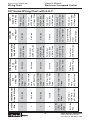
Wiring Chart
E.O.C. Box
Ford Circuit #2242 Ford Circuit #2242
Lt. Blue
Orange
Orange
w/Yellow
Stripe
Ground
Not Used
2
4
Not Used
1
Chelsea 2005-2007 Super
Wire
Duty w/6.0L Diesel
Bulletin HY25-1650-M1/US
Owner’s Manual
Electronic Overspeed Control
247 Series Wiring Chart with E.O.C.
Parker Hannifin Corporation
Chelsea Products Division
Olive Branch, MS 38654 USA
16
Speed Sensor Extension Cable
328923-10X (10 Ft, Supplied w/E.O.C. Option)
328923-5X (5 Ft, Optional Cable)
(4.9")
(1.8")
Electronic Overspeed
Controller - 329650X
(1.0")
Saddle Splice Connector
Supplied by Installer
16 AWG Wire, Blue
16 AWG Wire, Green
16 AWG Wire, Black
Connect to Ground
1
Blue
379243
Speed Sensor
28-P-171
O-Ring
Wire “A”
16 AWG Wire and Connector
Supplied by Installer
Run Wires through
Grommet in Firewall
Drill 1" Hole
in Firewall
Red
379502 Pressure Switch
120-140 In-Lb
1
379504
Valve Connector
and Wire Assembly
Black
Electrical Ground
of Cab or Frame
Accepts #10 Screw
Installation Sketch
NOTES:
1)Strip Wire Ends .25" Prior to Installing in Spade Terminal or Butt Connector (As Necessary)
2)Reference Kit 329076X
Run Cable through
Grommet in Firewall
2-Wire Shielded
Cable
Accepts .25" Screw
Electrical Ground
of Cab or Frame
16 AWG Wire, Red
Connect to 12 VDC or 24 VDC
Slice Grommet
Insert in Hole
in Firewall
379625
Grommet
Bulletin HY25-1650-M1/US
Owner’s Manual
Electronic Overspeed Control
Electronic Over Speed Control (E.O.C.) Installation
Sketch for 890 Series (SK-475)
Parker Hannifin Corporation
Chelsea Products Division
Olive Branch, MS 38654 USA
17
(4.9")
Connect to
Green Wire
from E.O.C.
Connect to
Blue Wire from E.O.C.
Red Wire
Blue Wire
28-P-171
O-Ring
Speed Sensor Extension Cable
328923-10X (10 Ft Supplied w/E.O.C.)
328923-5X (5 Ft Optional Cable)
379243
Speed Sensor
Run Cable through
Grommet in Firewall
(1.8")
Electronic Overspeed
Controller - 329650X
(1.0")
16 AWG Wire, Blue
16 AWG Wire, Green
16 AWG Wire, Red
Connect per Wiring Chart
page 18
Accepts 1/4" Screw
380089
Adapter
379698
90° Elbow
RELAY
To 6R140 Transmission
High Pressure Port
2 See Torque Note
379502
Pressure Switch
329232-1X
Hose Assembly
329617X
Wire Harness
See Wiring Chart page 18
3/8" Stud Size Ring Terminal
Installation Sketch
NOTES:
1)Reference Kits:
329255-12X
329601X
2)Caution: Torque Values must be Maintained 120-144 In-Lb
3)Strip Wire Ends 0.25" Prior to Installing Connector
Connector and 2-Wire
Shielded Cable
The Clutch Master Cylinder Seal
Assembly is Located on the Engine
Compartment Firewall on the
Driver’s Side Near the Brake Master
Cylinder
379817 Grommet
Slice Grommet.
Insert in Hole in Clutch
Master Cylinder Seal
Assembly
Cut 1.00" Hole in Firewall
Near Ford Clutch Master
Cylinder Seal Assembly
Firewall Pass-Through Installation
16 AWG Wire, Black
Connect to Ground
Electrical Ground of Cab
Bulletin HY25-1650-M1/US
Owner’s Manual
Electronic Overspeed Control
Electronic Over Speed Control (E.O.C.) Installation
Sketch for 248 Series (SK-489)
Parker Hannifin Corporation
Chelsea Products Division
Olive Branch, MS 38654 USA
A
B
Chelsea Wire
Ford PTOREF #LE434
White w/Brown Stripe
Ford PTORTN #RE327
©Gray w/Violet Stripe
Ford PTO_RPM #CE914 Green
Ford PTO_RLY #CE 326
Blue w/White Stripe
Ford Chassis Ground in Dash
Ford PTORS1 #CE912 Yellow
w/Green Stripe
Chelsea E.O.C. Blue Wire
Chelsea E.O.C. Green Wire
Stationary Mode
Ford PTOREF #LE434
White w/Brown Stripe
Ford PTORTN #RE327
Gray w/Violet Stripe
Ford PTO_RPM #CE914 Green
Ford PTO_RLY #CE 326
Blue w/White Stripe
Ford Chassis Ground in Dash
Ford PTORS2 #CE933
(1) Blue w/Orange Sripe
Chelsea E.O.C. Blue Wire
Chelsea E.O.C. Green Wire
Mobile Mode
18
Red Wire
Black w/Ring Terminal
Mobile Mode
Ford 12V #CDC64
Yellow w/Orange Stripe
Ford Chassis Ground in Dash
Stationary Mode
Ford 12V #CDC64 Yellow w/Orange Stripe
Ford Chassis Ground in Dash
Chelsea E.O.C. Wire
E.O.C. Wires
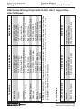
Wiring Chart
NOTE: (1) Early MY2011 Product Units may come with two Blunt Cut Blue w/Gray Stripe wires. One wire will be
for P.T.O. Function (PTORS2) the other will be a Customer Wire for “Park Only Output” (TRO-P). Refer to Ford
Body Builders web site for more on this subject.
White Wire
Gray Wire
Green Wire
Blue w/White Stripe
Black w/Ring Terminal
Yellow Wire
Blue Wire
Red Wire
Bulletin HY25-1650-M1/US
Owner’s Manual
Electronic Overspeed Control
248 Series Wiring Chart with E.O.C. 2011 Super Duty
w/6.7L Diesel
Parker Hannifin Corporation
Chelsea Products Division
Olive Branch, MS 38654 USA
Bulletin HY25-1650-M1/US
Installation Instructions
Owner’s Manual
Electronic Overspeed Control
Control Adjustment Instructions
Selecting the Overspeed R.p.m.:
This is usually based on safety, noise control or fuel economy considerations.
The high limit set point should be set no greater than the maximum speed
allowed by the manufacturer of the driven equipment, and the engine, BUT
IN NO CASE GREATER THAN 3000 R.P.M.
Selecting the Reset R.p.m.:
The control is set to provide a reset, after an over-speed disengagement.
The automatic reset should be set above the engine fast idle speed, BUT NO
GREATER THAN 1000 R.P.M.
Safety Precautions and Preparations:
The control settings are to be made with the engine running – provide
adequate ventilation and exhaust elimination or make the adjustments
outdoors. Put the vehicle transmission in neutral, set the vehicle brakes and
chock the wheels.
Disengage the driven equipment.
Connect a tachometer to the engine, if there is not one in the vehicle.
Description of Re-Engagement Modes
1.Manual Engagement Mode- In this mode the user must manually depress
the On/Off button to re-engage the P.T.O. after an Overspeed condition.
NOTE: The unit is preset from the factory in this mode
2.Auto Engagement Mode- In this mode the unit automatically re-engages
the P.T.O. after an Overspeed condition and the lower set point has been
reached.
WARNING: When the Parker Chelsea Electronic Overspeed
Controller is set up in Auto Re-engagement Mode, the P.T.O. will
automatically engage when the engine RPM reaches the lower preset point
thus causing the driven equipment to become operable. The vehicle or
equipment operator must therefore make certain that other persons and
property are not in a position to be crushed, impacted, caused to fall or
otherwise injured when re-engagement occurs.
19
Parker Hannifin Corporation
Chelsea Products Division
Olive Branch, MS 38654 USA
Bulletin HY25-1650-M1/US
Installation Instructions
Owner’s Manual
Electronic Overspeed Control
Control Adjustment Instructions (Continued)
Setting Procedure - Re-Engagement Modes
1. Turn on the unit to set the re-engage modes.
2. By depressing the Brightness (“B”) and High Limit Set (“H”) buttons
simultaneously the unit’s mode of re-engagement is changed from
“Manual Engagement Mode” to “Auto Engagement Mode”. Both the
red and yellow LED’s flash once to notify the installer the unit is in “Auto
Engagement Mode”. In “Auto Engagement Mode” the P.T.O. re-engages
automatically once the engine’s R.P.M. reach the lower set point.
3. Depressing the “B” and “H” buttons simultaneously again switches the unit
from “Automatic Engagement Mode” back to “Manual Engagement Mode”.
Both the red and yellow LED’s flash twice to notify the installer the unit is
in “Manual Engagment Mode”.
Setting Procedure - Speed Limits
1. Start the engine and allow it to idle. The “On/Off” button will be illuminated
white to indicate the unit is turned Off. The P.T.O. should be disengaged.
2. Turn the system On by depressing the “On/Off” button. You must hold the
button down for 0.5 seconds for the unit to turn On. When turned On, the
“On/Off” button will turn from white to red, the P.T.O. will engage and the
red “P.T.O. Engaged” will illuminate.
3. Ramp up the vehicle’s R.P.M. to the R.P.M. the user desires the P.T.O. to
automatically disengage. Depress the “H” (High Limit) button on the
bottom of the unit using a small tool or pencil point. The yellow “Over
Speed” will illuminate, the P.T.O. will disengage, the red “P.T.O. Engaged”
will turn off.
4. Slowly let the vehicle’s R.P.M. fall to the lower R.P.M. setting where the
user desires the P.T.O. to be able to be re-engaged. Depress the “L” (Low
Limit) button on the bottom of the unit using a small tool or pencil point.
The yellow “Over Speed” will turn off and the “On/Off” button will be red
and flashing. Further lower the R.P.M. slightly. The “On/Off” button flashing
20
Parker Hannifin Corporation
Chelsea Products Division
Olive Branch, MS 38654 USA
Bulletin HY25-1650-M1/US
Installation Instructions
Owner’s Manual
Electronic Overspeed Control
Control Adjustment Instructions (Continued)
red indicates that the unit is ready to re-engage the P.T.O.
5. Depress the flashing “On/Off” button to re-engage the P.T.O. The P.T.O. will
engage and the red “P.T.O. Engaged” will illuminate.
6. If the unit is in the “AUTOMATIC Engagement Mode” the P.T.O. will be
engaged automatically when the “L” (Low Limit) Button is depressed.
7. These settings are permanently held in memory until they are changed or
the user resets the unit to the “Default” mode.
8. To reset the unit to the “Default” mode the E.O.C. must be turned Off.
Depress both the “L” and “H” buttons simultaneously. All LED’s will flash
3 times to acknowledge the unit has been reset to the default mode. In the
“Default” mode, only the “On/Off” button is active and the over speed
feature is inactive. The unit may be used in this mode if desired.
Setting the LED Brightness
1. The LED brightness can be adjusted to (4) different intensities. Locate the
“B” button on the bottom of the unit.
2. Continuously depress the “B” button until the desired brightness is
obtained.
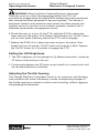
Final Installation of the Control:
After the overspeed and the reset set points are correctly set, complete the
installation of the control, under the dash or on the engine housing, utilizing
the supplied bracket and hardware. Be sure the E.O.C. unit is located within
easy reach of the operator and is clearly visible.
.28
Brightness
(“B”)
High Limit Set
(“H”)
21
Low Limit Set
(“L”)
Parker Hannifin Corporation
Chelsea Products Division
Olive Branch, MS 38654 USA
Bulletin HY25-1650-M1/US
Operating Instructions
Owner’s Manual
Electronic Overspeed Control
Before Starting the Engine
With the vehicle turned OFF, all lights in the E.O.C. unit should be OFF.
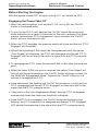
Engaging the Power Take-Off
1.When the vehicle ignition is on and the E.O.C. unit is Off, the “On/Off”
button is illuminated white.
2.To turn On the E.O.C. unit, depress the “On/Off” button. You must hold
down the button for at least 0.5 seconds for the unit to activate. This helps
prevent unintentional P.T.O. engagement. Upon activation the “On/Off”
button will turn from white to red.
3.When the P.T.O. engages, the pressure switch will close and the red “P.T.O.
Engaged” will illuminate.
4.Should the operating R.P.M. reach the Overspeed set point, the yellow
“Over Speed” will illuminate, the P.T.O. will disengage and the red “P.T.O.
Engaged” will turn off due to the lack of a signal from the P.T.O. pressure
switch.
5.To re-engage the P.T.O. lower the vehicle R.P.M. to less than the lower set
point.
a.When the lower R.P.M. set point is reached, the yellow “Over Speed” will
turn off and the red backlight on the “On/Off” button will begin to flash if in
the “MANUAL Engagement Mode”. Depress the “On/Off” button for 0.5
second to re-engage the P.T.O.
b.Once depressed, the flashing red “On/Off” button returns to solid red, the
P.T.O. re-engages and the red “P.T.O. Engaged” will illuminate due to the
signal from the P.T.O. pressure switch.
c.If the unit is in the “Auto Engagement Mode” then the P.T.O. re-engages
automatically when the lower rpm threshold is reached.
d.Once the P.T.O. is re-engaged, the “On/Off” button red backlight stops
flashing, the P.T.O. solenoid is re-energized and the red “P.T.O. Engaged”
LED should illuminate due to the signal from the P.T.O. pressure switch.
22
Parker Hannifin Corporation
Chelsea Products Division
Olive Branch, MS 38654 USA
Owner’s Manual
Electronic Overspeed Control
Bulletin HY25-1650-M1/US
Operating Instructions
WARNING: When the Parker Chelsea Electronic Overspeed
Controller is set up in Auto Re-engagement Mode, the P.T.O. will
automatically engage when the engine RPM reaches the lower preset point
thus causing the driven equipment to become operable. The vehicle or
equipment operator must therefore make certain that other persons and
property are not in a position to be crushed, impacted, caused to fall or
otherwise injured when re-engagement occurs.
6.Should the user try to turn On the P.T.O. while the R.P.M. is above the
lower set point, the yellow “Over Speed” will illuminate, the “On/Off” button
will turn from white to flashing red but the P.T.O. will not engage.
7.Reduce the R.P.M. till it is below the lower set point, the yellow “Over
Speed” will turn off and the “On/Off” button will continue to flash. Depress
the “On/Off” button for 0.5 seconds to engage the P.T.O.
Setting the LED Brightness
1. The LED brightness can be adjusted to (4) different intensities. Locate the
“B” button on the bottom of the unit.
2. Continuously depress the “B” button using a small tool or pencil point until
the desired brightness is obtained.
Adjusting the Throttle Opening
The Chelsea Electronic Overspeed Control is not a governor, and changing
load conditions will make it necessary to make corresponding changes in
the throttle opening to maintain a uniform rate of working, without lugging or
overspeeding the equipment.
23
Parker Hannifin Corporation
Chelsea Products Division
Olive Branch, MS 38654 USA
Bulletin HY25-1650-M1/US
Installation Instructions
Owner’s Manual
Electronic Overspeed Control
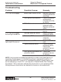
Troubleshooting
Problem
Possible Causes
Remedy
P.T.O. will not engage
Blown fuse in back of unit
Poor ground connections
P.T.O. Solenoid valve
E.O.C. control
P.T.O. will not engage
Shorted pressure switch
but red light comes on
Defective P.T.O.
P.T.O. engages, but red
Defective red LED
light doesn't come on
Open pressure switch
Poor ground connection on
pressure switch
Replace fuse with
3 amp automotive
stab fuse.
Check all ground
connections.
Connect securely
to chasis.
Check wiring to
solenoid valve.
Replace solenoid
valve.
Check wiring to
E.O.C.
Check wiring to
Pressure switch.
Check for
solenoid
malfunction.
Replace E.O.C.
unit.
Check wiring to
pressure switch.
Check that
ground is secure
to chassis.
Check that
ground is secure
to chassis.
NOTE: Unit should be checked periodically to make sure speed sensor is
operating. Speed sensor is checked by going to overspeed condition. If
yellow light does NOT come on in overspeed condition, speed sensor may
not be operating or the E.O.C. unit may be in Default Mode. See “Setting
Procedure”. This could also indicate that control box is not operating either.
Wiring harness should also be checked for breaks or disconnections.
24
Parker Hannifin Corporation
Chelsea Products Division
Olive Branch, MS 38654 USA
Owner’s Manual
Electronic Overspeed Control
Bulletin HY25-1650-M1/US
Power Take-Off Maintenance
Power Take-Off Maintenance
Due to the normal and sometime severe torsional vibrations that Power TakeOff units experience, operators should follow a set maintenance schedule
for inspections. Failure to service loose bolts or Power Take-Off leaks could
result in potential auxiliary Power-Take-Off or transmission damage.
Periodic P.T.O. MAINTENANCE is required by the owner/operator to ensure
proper, safe and trouble free operation.
Daily:
Check all air, hydraulic and working mechanisms before operating
P.T.O. Perform maintenance as required.
Monthly:Inspect for possible leaks and tighten all air, hydraulic and
mounting hardware, if necessary. Torque all bolts, nuts, etc. to
Chelsea specifications. Ensure that splines are properly
lubricated, if applicable. Perform maintenance as required.
With regards to the direct mounted pump splines, the P.T.O. requires the
application of a specially formulated anti-fretting, high pressure, high
temperature grease. The addition of the grease has been proven to reduce
the effects of the torsional vibrations, which result in fretting corrosion on the
P.T.O. internal splines as well as the pump external splines. Fretting
corrosion appears as a “rusting and wearing” of the pump shaft splines.
Severe duty applications, which require long P.T.O. running times and high
torque may require more frequent regreasing. Applications such as Utility
Trucks that run continuously and are lightly loaded also require frequent
regreasing due to the sheer hours of running time. It is important to note that
service intervals will vary for each and every application and is the
responsibility of the end user of the product. Chelsea also recommends
that you consult your pump owners manuals and technical services for their
maintenance guidelines. Fretting corrosion is caused by many factors and
without proper maintenance; the anti-fretting grease can only reduce its
effects on components.
Chelsea offers the grease to our customers in two packages. The first is a
5/8 fluid ounce tube (379688), which is included with every applicable P.T.O.,
and the second is a 14-ounce grease cartridge (379831). Chelsea also offers
greaseable shafts for most all output designators.
Warranty: Failure to comply entirely with the provisions set forth in
the appropriate Owner’s Manual will result in voiding of ALL
Warranty consideration.
25
Parker Hannifin Corporation
Chelsea Products Division
Olive Branch, MS 38654 USA
Notes
26
Parker Hannifin Corporation
Chelsea Products Division
Olive Branch, MS 38654 USA
Offer of Sale
The items described in this document and other documents or descriptions provided by Parker Hannifin Corporation, its subsidiaries
and its authorized distributors are hereby offered for sale at prices to be established by Parker Hannifin Corporation, its subsidiaries
and its authorized distributors. This offer and its acceptance by any customer ("Buyer") shall be governed by all of the following Terms
and Conditions. Buyer’s order for any such items, when communicated to Parker Hannifin Corporation, its subsidiary or an authorized
distributor ("Seller") verbally or in writing, shall constitute acceptance of this offer.
1. Terms and Conditions of Sale: All descriptions, quotations,
proposals, offers, acknowledgments, acceptances and sales of
Seller’s products are subject to and shall be governed exclusively
by the terms and conditions stated herein. Buyer’s acceptance of
any offer to sell is limited to these terms and conditions. Any terms
or conditions in addition to, or inconsistent with those stated herein,
proposed by Buyer in any acceptance of an offer by Seller, are
hereby objected to. No such additional, different or inconsistent
terms and conditions shall become part of the contract between
Buyer and Seller unless expressly accepted in writing by Seller.
Seller’s acceptance of any offer to purchase by Buyer is expressly
conditional upon Buyer’s assent to all the terms and conditions
stated herein, including any terms in addition to, or inconsistent with
those contained in Buyer’s offer, Acceptance of Seller’s products
shall in all events constitute such assent.
2. Payment: Payment shall be made by Buyer net 30 days from
the date of delivery of the items purchased hereunder. Amounts
not timely paid shall bear interest at the maximum rate permitted
by law for each month or portion thereof that the Buyer is late in
making payment. Any claims by Buyer for omissions or shortages
in a shipment shall be waived unless Seller receives notice thereof
within 30 days after Buyer’s receipt of the shipment.
3. Delivery: Unless otherwise provided on the face hereof, delivery
shall be made F.O.B. Seller’s plant. Regardless of the method of
delivery, however, risk of loss shall pass to Buyer upon Seller’s
delivery to a carrier. Any delivery dates shown are approximate only
and Seller shall have no liability for any delays in delivery.
4. Warranty: Seller warrants that certain Products, namely PTOs,
SEMs, and Wet Line Kits sold hereunder shall be free from defects
in material or workmanship for a period of twenty four months
from the date of delivery to Buyer. Seller warrants that certain
Products namely Pumps, and Hydraulic Accessories shall be free
from defects in material or workmanship for a period of eighteen
months from the date of delivery to the Buyer. The prices charged
for Seller's products are based upon the exclusive limited warranty
stated above, and upon the following disclaimer: DISCLAIMER OF
WARRANTY: THIS WARRANTY COMPRISES THE SOLE AND
ENTIRE WARRANTY PERTAINING TO PRODUCTS PROVIDED
HEREUNDER. SELLER DISCLAIMS ALL OTHER WARRANTIES,
EXPRESS AND IMPLIED, INCLUDING MERCHANTABILITY
AND FITNESS FOR A PARTICULAR PURPOSE.
5. Limitation Of Remedy: SELLER’S LIABILITY ARISING FROM
OR IN ANY WAY CONNECTED WITH THE ITEMS SOLD OR
THIS CONTRACT SHALL BE LIMITED EXCLUSIVELY TO REPAIR OR REPLACEMENT OF THE ITEMS SOLD OR REFUND
OF THE PURCHASE PRICE PAID BY BUYER, AT SELLER’S
SOLE OPTION. IN NO EVENT SHALL SELLER BE LIABLE FOR
ANY INCIDENTAL, CONSEQUENTIAL OR SPECIAL DAMAGES
OF ANY KIND OR NATURE WHATSOEVER, INCLUDING BUT
NOT LIMITED TO LOST PROFITS ARISING FROM OR IN ANY
WAY CONNECTED WITH THIS AGREEMENT OR ITEMS SOLD
HEREUNDER,WHETHER ALLEGEDTO ARISE FROM BREACH
OF CONTRACT, EXPRESS OR IMPLIED WARRANTY, OR IN
TORT, INCLUDING WITHOUT LIMITATION, NEGLIGENCE,
FAILURE TO WARN OR STRICT LIABILITY.
6. Changes, Reschedules and Cancellations: Buyer may request
to modify the designs or specifications for the items sold hereunder
as well as the quantities and delivery dates thereof, or may request
to cancel all or part of this order, however, no such requested modification or cancellation shall become part of the contract between
Buyer and Seller unless accepted by Seller in a written amendment
to this Agreement. Acceptance of any such requested modification
or cancellation shall be at Seller’s discretion, and shall be upon
such terms and conditions as Seller may require.
7. Special Tooling: A tooling charge may be imposed for any
special tooling, including without limitation, dies, fixtures, molds
and patterns, acquired to manufacture items sold pursuant to this
contract. Such special tooling shall be and remain Seller’s property
notwithstanding payment of any charges by Buyer. In no event will
Buyer acquire any interest in apparatus belonging to Seller which
is utilized in the manufacture of the items sold hereunder, even if
such apparatus has been specially converted or adapted for such
manufacture and notwithstanding any charges paid by Buyer. Unless otherwise agreed, Seller shall have the right to alter, discard
or otherwise dispose of any special tooling or other property in its
sole discretion at any time.
8. Buyer’s Property: Any designs, tools, patterns, materials, drawings, confidential information or equipment furnished by Buyer or
any other items which become Buyer’s property, may be considered
obsolete and may be destroyed by Seller after two (2) consecutive
years have elapsed without Buyer placing an order for the items
which are manufactured using such property, Seller shall not be
responsible for any loss or damage to such property while it is in
Seller’s possession or control.
9. Taxes: Unless otherwise indicated on the face hereof, all prices
and charges are exclusive of excise, sales, use, property, occupational or like taxes which may be imposed by any taxing authority
upon the manufacture, sale or delivery of the items sold hereunder.
If any such taxes must be paid by Seller or if Seller is liable for the
collection of such tax, the amount thereof shall be in addition to
the amounts for the items sold. Buyer agrees to pay all such taxes
or to reimburse Seller therefore upon receipt of its invoice. If Buyer
claims exemption from any sales, use or other tax imposed by any
taxing authority, Buyer shall save Seller harmless from and against
any such tax, together with any interest or penalties thereon which
may be assessed if the items are held to be taxable.
10. Indemnity For Infringement of Intellectual Property Rights:
Seller shall have no liability for infringement of any patents,
trademarks, copyrights, trade dress, trade secrets or similar rights
except as provided in this Part 10. Seller will defend and indemnify
Buyer against allegations of infringement of U.S. Patents, U.S.
Trademarks, copyrights, trade dress and trade secrets (hereinafter
‘Intellectual Property Rights’). Seller will defend at its expense
and will pay the cost of any settlement or damages awarded in an
action brought against Buyer based on an allegation that an item
sold pursuant to this contract infringes the Intellectual Property
Rights of a third party. Seller’s obligation to defend and indemnify
Buyer is contingent on Buyer notifying Seller within ten (10) days
after Buyer becomes aware of such allegations of infringement,
and Seller having sole control over the defense of any allegations
or actions including all negotiations for settlement or compromise.
If an item sold hereunder is subject to a claim that it infringes the
Intellectual Property Rights of a third party, Seller may, at its sole
expense and option, procure for Buyer the right to continue using
said item, replace or modify said item so as to make it noninfringing,
or offer to accept return of said item and return the purchase price
less a reasonable allowance for depreciation. Notwithstanding the
foregoing, Seller shall have no liability for claims of infringement
based on information provided by Buyer, or directed to items
delivered hereunder for which the designs are specified in whole
or part by Buyer, or infringements resulting from the modification,
combination or use in a system of any item sold hereunder. The
foregoing provisions of this Part 10 shall constitute Seller’s sole
and exclusive liability and Buyer’s sole and exclusive remedy for
infringement of Intellectual Property Rights.
If a claim is based on information provided by Buyer or if the
design for an item delivered hereunder is specified in whole or
in part by Buyer, Buyer shall defend and indemnify Seller for all
costs, expenses or judgments resulting from any claim that such
item infringes any patent, trademark, copyright, trade dress, trade
secret or any similar right.
11. Force Majeure: Seller does not assume the risk of and shall not
be liable for delay or failure to perform any of Seller’s obligations by
reason of circumstances beyond the reasonable control of Seller
(hereinafter ‘Events of Force Majeure’). Events of Force Majeure
shall include without limitation, accidents, acts of God, strikes or
labor disputes, acts, laws, rules or regulations of any government
or government agency, fires, floods, delays or failures in delivery of
carriers or suppliers, shortages of materials and any other cause
beyond Seller’s control.
12. Entire Agreement/Governing Law: The terms and conditions
set forth herein, together with any amendments, modifications and
any different terms or conditions expressly accepted by Seller in
writing, shall constitute the entire Agreement concerning the items
sold, and there are no oral or other representations or agreements
which pertain there/to. This Agreement shall be governed in all
respects by the law of the State of Ohio. No actions arising out of
the sale of the items sold hereunder or this Agreement may be
brought by either party more than two (2) years after the cause of
action accrues.
10/09-P
27
Parker Hannifin Corporation
Chelsea Products Division
Olive Branch, MS 38654 USA
Parker Hannifin Corporation
Chelsea Products Division
8225 Hacks Cross Road
Olive Branch, Mississippi 38654 USA
Tel: (662) 895-1011
Fax:(662) 890-5379
www.parker.com/chelsea
TST 05/10 1C