1
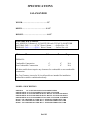
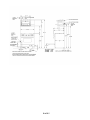
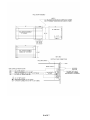
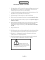
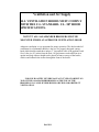
Installation and Operation Instructions for
the BlueStar Infra-Red Salamander Broiler
THIS PRODUCT WAS DESIGNED FOR EASE OF INSTALLATION AND
OPERATION.HOWEVER, WE RECOMMEND THAT YOU READ ALL
SECTIONS OF THIS MANUAL BEFORE BEGINNING INSTALLATION AND
THAT YOUR BROILER IS INSTALLED BY AN APPROVED GAS
INSTALLATION TECHNICIAN IN ACCORDANCE WITH THE LOCAL
CODES, OR IN THE COMMONWEALTH OF MASSACHUSETTS A
LICENCED PLUMBER OR LICENCED GAS FITTER, CAPABLE OF
REVIEWING AND PREFORMING THE MANUFACTURES INSTALLATION
CHECKLIST INCLUDED IN YOUR INFORMATION PACKET.
PLEASE DO NOT REMOVE PERMANENTLY AFFIXED LABELS,
WARNINGS, OR DATAPLATES FROM THE UNIT, AS THIS MAY VOID THE
MANUFACTURER’S WARRANTYAND/OR HINDER EFFECTIVE SERVICING
AND MAINTAINCE
WARNING: IF THE INFORMATION IN THIS MANUAL IS NOT
FOLLOWED EXACTLY, A FIRE OR EXPLOSION MAY RESULT
CAUSING PROPERTY DAMAGE, PERSONAL INJURY OR
DEATH.
- Do not store or use gasoline or other flammable vapors and liquids in the
vicinity of this or any other appliance.
-
WHAT TO DO IF YOU SMELL GAS
• Do not try to light any appliance.
• Do not touch any electrical switch.
• Do not use any phone in your building.
• Immediately call your gas supplier from a neighbor’s phone. Follow the
gas supplier’s instructions.
• If you cannot reach your gas supplier, call the fire department.
- A qualified installer, service agency or the gas supplier, must perform
installation and service.
THIS APPLIANCE MUST BE MOUNTED UNDER AN APPROVED
VENTILATION HOOD. CONTACT A LICENSED GAS CONTRACTOR IN
ACCORDANCE WITH THE LOCAL CODES (OR IN THE ABSENCE OF
LOCAL CODES, WITH THE NATIONAL FUEL GAS CODE, ANSI
Z223.1/NFPA 54) FOR INSTALLATION.
This appliance is not intended to be installed underneath a cabinet.
This appliance must be electrically grounded in accordance with the local codes or, in
the absence of local codes, with the National Electrical Code, ANSI/NFPA 70.
The appliance and its individual shutoff valve must be disconnected from the gas supply
piping system during any pressure testing of that system at test pressures in excess of ½
psi (3.5 kPa).
The appliance must be isolated from the gas supply piping system by closing its
individual manual shutoff valve during any pressure testing of the gas supply piping
system at test pressures equal to or less than ½ psi (3.5 kPa).
The appliance must not be used for space heating purposes.
The cooking area or the exterior top areas are not for storage purposes.
The appliance must be disconnected from the electrical supply before servicing.
This appliance comes set for the type of gas as specified on the rating plate and tag on
the unit. If a different type of gas is required, please contact your local authorized gas
technician.
Leak Testing of the appliance shall be conducted according to the manufacturer’s
instructions.
WARNING
Electrical Grounding Instructions
This appliance is equipped with a three-prong grounding plug for your protection
against shock hazard and should be plugged directly into a properly grounded
receptacle. Do not cut or remove the grounding prong from this plug.
TABLE OF CONTENTS
TABLE OF CONTENTS………………1
GENERAL INFORMATION…………2
SPECIFICATIONS…………………….3
DIMENSIONS & MODELS…………..4, 5,6&7
INSTALLATION………………………8,9, &10
VENTILATION AND AIR SUPPLY…11
OPERATION………………………….. 12&13
WIRING DIAGRAM…………………..14
COOKING GUIDE………………….…15
MAINTAINCE……………………...….16
CHECKLIST
WARRANTY & SERVICE
KEEP APPLIANCE AREA FREE AND
CLEAR FROM -COMBUSTIBLES-
PAGE 1 OF 16
GENERAL INFORMATION
The Infra-Red Salamander Broiler is designed to be a High Speed Cooking
Appliance.
It is ideal for preparing a variety of meats, fish, melted cheese dishes, casseroles, au
gratin dishes, soufflé’s, French onion soup, and other ethnic foods.
I. R. BROILER PERFORMANCE and
CONSTRUCTION
Two Hi-Low gas valves provide individual control of the (2) atmospheric- type
10,500 BTU gas Infra-Red burners for the salamander. The “LO” position is
adjustable for most field gas pressure situations. The high-efficiency, Infra-Red
burners provide fast pre-heat and uniform production. Unique atmospheric burner
design eliminates the need for fans or filters to assist in the operation of the appliance.
Heat is directed downward to the large heavy duty broiling rack. The rack is easily
removed from the spring balanced lower rack assembly. The inner rack assembly
rolls out for ease of loading and unloading. Rack assembly raises and lowers with
positive locking in four positions. A full- width grease deflector attached to the
underside of the rack assembly channels hot drippings to a large capacity drain pan
even when the rack assembly is rolled out. (Drain pan must always be attached
during use). The rack assembly and drain pan are easily removed for cleaning. When
mounted the I.R. Broiler is supported by heavy-formed Stainless Steel brackets. The
Broiler construction consists of an all Stainless Steel interior and exterior, which
provides unmatched quality and durability for many, many years.
PAGE 2
SPECIFICATIONS
SALAMANDER
WIDTH…………………………………….25”
DEPTH…………………………………..19 1/2”
HEIGHT…………………………………..16 1/2”
GAS SPECIFICATIONS:
ALL MODELS (2) Burners @ 10,500 BTU/HR each. TOTAL 21,000 BTU/HR
NATURAL GAS-----------@ 5.0” Water Column,……..Orifice Size = 54
PROPANE [email protected] Water Column,……..Orifice Size = 64
Minimum Clearances:
Sides
Rear
6”
0”
6”
0”
Top
PRZSAL24:
Combustible Construction
Non-Combustible Construction
N/A
N/A
All other models do not require any clearances for combustible or non-combustible
construction.
The Top Clearance is noted as N/A as all models are intended for installation
underneath a suitable ventilation hood only.
MODEL # DESCRIPTION
PRZSAL24
-24” COUNTER TOP SALAMANDER W/LEGS
PRZSAL24WM -24” SALAMANDER W/WALL MOUNT SYSTEM
PRZSAL36WM -36”SALAMANDER W/WALL MOUNT SYSTEM AND SHELF
PRZSAL48WM -48”SALAMANDER W/WALL MOUNT SYSTEM AND SHELF
PRZSAL60WM -60” SALAMANDER W/WALL MOUNT SYSTEM AND SHELF
BG3617 -SALAMANDER 36” WIDE BY 17” INTERGRATED BACKGUARD
BG4817 –SALAMANDER 48” WIDE BY 17” INTERGRATED BACKGUARD
BG6017 –SALAMANDER 60” WIDE BY 17” INTERGRATED BACKGUARD
PAGE 3
PAGE 4
PAGE 5
PAGE 6
PAGE 7
INSTALLATION
The importance of the proper installation of the Gas Cooking Equipment cannot be
over stressed. Proper performance of the equipment is dependent, in great part, on the
compliance of the installation with the manufacture’s specifications.
Installation must conform to local codes or, in the absence of local codes, with the
National Fuel Code,
ANSI Z223.1 National Gas Installation Code,
CAN/CGA-B149.1, or the Propane Installation Code,
CAN/CGA-B149.2, as applicable.
Before assembly and connection, check gas supply.
A. The type of gas for which the unit is equipped is stamped on the data plate
located behind the right access panel of the unit. Connect a unit stamped
“NAT” only to natural gas supply: connect those stamped L.P. only to the
propane gas supply.
B. If it is a new installation, have gas authorities check meter size and piping to
assure that the unit is supplied with sufficient amount of gas pressure required
to operate the unit.
C. If it is additional equipment or replacement have a qualified gas technician
check the gas pressure to make certain that existing gas facilities (meter,
piping, etc.) will deliver the BTU’S of gas required at the unit with no more
than ½” water column pressure drop. When checking pressure be certain that
other equipment on the same gas line is on and at full rate. A pressure
regulator is supplied with the unit pre-set at the factory for the type of gas that
was specified. The pressure regulator is located behind the left access panel of
the unit
D. The appliance and its individual shut off valve (supplied by others) must be
disconnected from the gas supply piping system during any pressure testing of
that system at pressures in excess of ½” psi (3,45 kPa).
E. Gas supply connection is made in back lower left hand corner of the unit. A
Readily accessible approved type gas hand valve (supplied by others) should
be installed on each supply line. TEST FOR LEAKS; DO NOT USE AN
OPEN FLAME.
NOTE!!! THE PRESSURE REGULATOR IS LOCATED INSIDE THE
UNIT. TO GAIN ACCESS TO IT, REMOVE THE LEFT SIDE ACCESS
PANEL OF THE UNIT.
Make certain that the new piping, joints and connections have been made in a
clean manner and have been purged, so that the piping chips, compound, etc. will
not clog the valves and/or controls. Use pipe joint sealant that is resistant to
liquefied petroleum gas
Warning:
Check gas connections for leaks. Use a soap solution or similar means
DO NOT USE AN OPEN FLAME!
PAGE 8
INSTALLATION
WALL MOUNTED SALAMANDER AND
SHELF ASSY FOR 36”, 48” AND 60” WIDE UNITS
1. Each gas appliance shall be located with respect to building construction and
Other Equipment so as to permit access to the appliance. Such access and
Clearance is necessary for service and cleaning.
2. A welded wall mounted Salamander and shelf assembly, which includes two
(2) hi-hat supports, one (1) lower support angle, one (1) upper support angle,
one (1) rear shelf panel, one (1) shelf, and one Salamander bottom panel.
Also hardware required for attachment of components.
3. Review pages 4 & 5 as a reference for mounting the wall mount kit. Drilled
Holes are required in both the upper and lower Lt. to Rt. Supports (ADDED
BY OTHERS), before any mounting can take place. NOTE!!!! Installer is
Responsible for mounting hardware as well as insuring that the wall
mount assembly once positioned in place can support a minimum of 200
lbs.
4. After the wall mount unit has been installed, remove the second screw back
from the front top piece (1) from the left side (1) from the right side. Slide the
Salamander in between the flanges of the wall mount assembly. By keeping
the front flush with the Wall mount brackets, the bottom mounting holes
should line up. With the (4) ¼ -20 x 1” bolts supplied from the factory, secure
the Salamander to the Bottom flanges of the wall mount assembly.
5. Attach the upper shelf angle to the top rear support with (2) sheet metal
screws
provided. Attach the lower shelf angle to the bottom rear support
with (2) sheet Metal screws provided.
6. Next position and attach the shelf back panel to the (2) angles added in step
(6).
7. Attach the shelf with (3) 10-24 machine screws provided. Make adjustments
as necessary.
8. Attach the bottom panel and use the (4) plug buttons to seal the ½” holes
9. Replace the (2) screws removed in step (5) assembly is complete.
PAGE 9
INSTALLATION
Salamander mount w/out shelf
1. Each gas appliance shall be located with respect to building construction and
other Equipment so as to permit access to the appliance. Such access and
clearance may be necessary for service and cleaning.
2. A welded wall mount bracket assembly provided, which includes two (2) hihat supports and a left and right wall, mount bracket.
3. One bottom panel, (4) sheet metal screws and (4) plug buttons
4. Holes required for mounting and hardware for mounting required by others
5. Once the wall mount bracket assembly is in place it is required to support a
minimum of 200 lbs.
6. Before sliding the Salamander in place remove the second screw back from
the front top piece from both the left and right side of the Salamander.
Connect the gas supply and check for gas leaks. DO NOT USE AN OPEN
FLAME.
8. Plug in electrical cord.
9. Slide Salamander to the rear of the assembly until the front of the unit is flush
The wall mounts brackets. Re-install the (2) screws removed from step (7).
10. With the (4) ¼ - 20 bolt provided secure the Salamander to the bottom .
flanges of the Lt./Rt. Wall mount brackets.
11. Secure the bottom panel with (4) sheet metal screws provided an plug the
½” dia. Holes with the (4) plug buttons. Assembly is complete.
WARNING NEVER use this
appliance as a space heater to heat or warm the
room. Doing so may result in carbon monoxide
poisoning and overheating of the oven.
PAGE 10
Ventilation and Air Supply
ALL VENTILATION HOODS MUST COMPLY
WITH THE U.L. STANDARD- U.L. 507 HOOD
SPECIFICATIONS.
NOTE!!!!! ALL SALAMANDER BROILERS MUST BE
MOUNTED UNDER AN APPROVED VENTILATION HOOD
Adequate ventilation is very important for proper operation. The ideal method of
ventilation for a Salamander Broiler is the use of a properly designed canopy
hood which should extend three inches (3”) beyond all sides of the appliance and
Six (6) feet six (6”) inches from the floor. All gas burners need sufficient air to
operate and large objects should not be placed in front or on top of the broiler,
which would obstruct the airflow through the front of the broiler.
FOR YOUR SAFTEY NEVER PLACE ANY TYPE OF OBJECT ON
TOP OF THE SALAMANDER BROILER AS THE TOP OF THE
BROILER CAN CAUSE SEVERE BURNS OR FIRE AND OBSTRUCT
VENTILATION.
PAGE 11
OPERATION
MAIN BURNER OPERATION:
1. Push and turn the lower valve dial to the left so that the HIGH position on the
dial is at 12:00. Immediately you will hear the spark igniter snapping and the
top front burner will ignite.
2. Note: Until the burner has an adequate amount of gas it will not ignite
3. Repeat the same procedure for the upper valve dial, which will ignite the top
rear burner.
4. When ignition has been accomplished a blue flame will be visible across the
Entire face of the Infra-Red burner. After approx. 2 ½ to 3 minutes the entire
Burner surface will glow a bright orange red color.
BURN OFF PERIOD
Many parts used in the manufacturing of this appliance have a thin protective
coating of oil. This oil should be burned off before the equipment is used for food
preparation. The same goes for the Infra-Red burners. Until the binders etc. are
burned off, the burners will emit a strong odor. Make sure your Range Hood is on
and in the High Position during this burn off period.
TO CONSERVE ENERGY:
Do not waste energy by leaving the controls in the HIGH temperature
settings during idle periods. We recommend you turn the appliance off. Very
seldom will you use the low setting on the burner dial. When this setting is
used, the burner will not burn the bright red orange color, but blue flames
will travel across the entire face of the burner.
SHUT DOWN INSTRUCTIONS:
Turn main burner valves to the “OFF’ position. If the unit is to be shut down for
an extended period of time, close the manual inline service valve to the off
position.
NOTE!! The inline service valve is not factory supplied.
FOR YOUR SAFETY NEVER PLACE ANY TYPE OF OBJECT ON TOP
OF THE SALAMANDER BROILER. THE TOP OF THE BROILER CAN
CAUSE SEVERE BURNS AND/OR FIRE AND WILL ALSO OBSTRUCT
VENTILATION.
PAGE 12
OPERATION
MAIN BURNER ADJUSTMENTS:
All Salamanders are provided with a fixed burner orifice to provide 10,500
BTU/HR per burner at the “MAX” setting for NATURAL gas supplied at 5.0”
W/C pressure and 10,500 BTU/HR per burner at the “MAX” setting on
PROPANE gas supplied at 10.0” W/C pressure.
The “LOW” setting is adjustable and should be set as follows:
1. Set the burner valve knob to the low setting and remove the burner knob.
2. Insert a thin bladed screwdriver into the valve stem to engage the slot inside
the stem.
3. Holding the valve stem turn the setscrew clockwise to decrease the rate and
counter clockwise to increase rate.
4. Proper adjustment is attained at a point where the burner flame travels back
and forth across the face of the ceramics. (If set too low a constant spark
will be continuous. If this occurs increase the low setting.)
This adjustment has been factory pre-set, however, with changing pressures this
adjustment may need to be re-done after installation.
THIS IS NOT CONSIDRED A MANUFACTURING DEFECT AND IS
NOT WARRANTABLE
WARNING NEVER cover any slots, holes or passages in the oven bottom or
cover an entire rack with materials such as aluminum foil. Doing so blocks airflow through
the oven and may cause carbon monoxide poisoning. Aluminum foil linings may also trap
heat, causing a fire hazard.
PAGE 13
PAGE 14
COOKING GUIDE
SOME OF THE ITEMS TESTED
ITEM
BURNER
SETTING
RACK
POSITION
EST. COOK
TIME
HI
3
4 MIN. PER SIDE (MED)
HI
3
4 MIN.PER SIDE (MED)
SAUSAGE (PRE- COOKED)
HI
2
7 MIN.TURNING)
HAMBURGER
HI
2
3 MIN. PER SIDE (MED)
CHICKEN PCS.(FULL RACK)
HI
1 OR 2
35 MIN.(TURNING)
HOT DOGS
HI
1
3 MIN.(TURNING)
HI
1
7 MIN.
HI
1
1 MIN.
STRIP (1 1/4) THICK
T- BONE
(1") THICK
FRENCH ONION SOUP (LARGE)
GARLIC BREAD
NOTE:
COOK TIMES WILL VARY DUE TO THE ITEMS THICKNESS AND ITEM PREFERENCE.
RACK POSITIONS AS TESTED ARE (1) BEING THE LOWEST TO (4) BEING THE HIGHEST.
THE # 4 POSITION WAS USED TO FINISH OFF SOME OF THE STEAK ITEMS TESTED. AGAIN THIS
WILL VARY DUE TO PREFERENCE.
PAGE 15
MAINTENANCE
A program of proper cleaning techniques will aid in continued trouble free
operation of this or any Quality equipment.
DAILY
The Grid Rack should be wiped daily while still warm, using a heavy cloth or other
grease absorbing material to remove grease and burnt food before they burn into the
grid. Remove burnt materials, such as carbonized grease or food, with a stiff wire
brush. DO NOT USE ANY TYPE OF STEEL WOOL.
Small particles may be left on the grid surface and get into the food products. Grid
rack should be washed thoroughly using a wire brush and a hot, mild detergent or
soap solution. Rinse with clear, warm water.
EXTERIOR AND INTERIOR CLEANING
Establish a regular cleaning schedule. Any spills should be wiped
Up immediately.
1. Wipe exposed, clean-able surfaces when cool with a mild detergent and hot
water. Stubborn spots may be removed with a lightweight non- metallic
scouring pad. Dry thoroughly with a clean cloth.
2. Stainless steel should be cleaned using a mild detergent, a soft cloth and hot
water. If it is necessary to use a non- metallic scouring pad, always rub in the
direction of the grain in the metal to prevent scratching. Use water based
stainless steel cleaner (such as Drackett Twinkel), if you want a high shine.
3. To remove the inner rack assembly, place lift handle in the lowest position,
pull the rack out as far as it will go. Remove the rack, and then remove the
drip chute and set aside. Push the rack assembly back into the unit as far as it
will go. Position the lift handle into the # 2 position. Carefully push down on
the rack handle, which should allow the rear rollers to lift up and out of the
roller guides. Now roll the rack assembly forward till you can grab it with
both hands to remove it completely. Once you clean the rack assembly and are
ready to re-install repeat the steps in reverse order.
IMPORTANT - THESE INSTRUCTIONS ARE TO REMAIN WITH THE
APPLIANCE AND THE CONSUMER IS TO RETAIN THEM FOR FUTURE
REFERENCE
PAGE 16