1
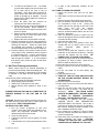
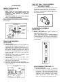
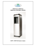
Installation and Service Guide
Point of Use Water Coolers
CONTENTS
Water Cooler Specifications........................................................................ 2
Set-up & Preparation Instructions ............................................................... 3
In-shop Unit Preparation ........................................................................... 3
Installation Instructions ............................................................................. 3
Service Information..................................................................................... 4
Lubrication ................................................................................................ 4
Periodic Maintenance................................................................................ 4
Hot Tank Cleaning .................................................................................... 5
Cabinet Cleaning ....................................................................................... 6
Operating Features ...................................................................................... 6
Troubleshooting .......................................................................................... 6
Accessories.................................................................................................. 7
Replacement Parts Pictorial Breakdown ..................................................... 8
Replacement Parts List................................................................................ 9
Wiring Diagram......................................................................................... 10
Filter/RO Warranty.................................................................................... 11
Cooler Warranty........................................................................................ 11
WATER COOLER
SPECIFICATIONS
Cook and Cold Models
PHT1AQK, PST1AQK
and PHF1AQK (-D100 series)
Voltage
Size
Shipping Weight (Approx)
Cold Water Capacity*
Compressor
Compressor (Full Load)
Refrigerant
Refrigerant Charge
115VAC +10%/1 PH/60 Hertz
43-1/2”(109cm)H., 13-1/2”(34cm)W., 16” (41cm)D.
60 lbs. (27kg)
.5 G.P.H. (1.9 L.P.H.)
1/20 HP
1.1 Amps
R 134a
1.875 oz. (53 grams)
Hot, Cook, and Cold Models
PHT1AQHK, PST1AQHK
and PHF1AQHK (-D200 series)
Voltage
Size
Shipping Weight (Approx)
Cold Water Capacity*
Hot Water Capacity
Compressor
Compressor (Full Load)
Refrigerant
Refrigerant Charge
115VAC +10%/1 PH/60 Hertz
43-1/2”(109cm)H., 13-1/2”(34cm)W., 16” (41cm)D.
63 lbs. (29kg)
.4 G.P.H. (1.5 L.P.H.)
45/6 oz. (45/175ml.) cups
1/20 HP
5.5 Amps
R 134a
1.875 oz. (53 grams)
* A.R.I. Ratings: Room Temperature 90°F(32°C); Supply Water Temperature
80°F (27°C); Drinking Water Temperature 50°F(10°C).
Specifications subject to change without notice.
** These units have been manufactured with R134a refrigerant. Repairs to the system must be performed by a
Certified Refrigeration Technician only. Always refer to the data plate located on the base of the unit for the
proper refrigerant and charge.
WARNING: A pressure regulator, such as a slow flow regulator, must be installed in front of the unit’s
water inlet if the water pressure (including any possible pressure spikes) could exceed 100
P.S.I.G. (690 kPA). Failure to comply will void the warranty. The manufacturer accepts no
liability for damage caused by excessive water pressure.
Do not use this drinking water system where the source water is microbiologically unsafe or with water of
unknown quality without adequate disinfection before or after the unit.
031666-011 Rev B
Page 2 of 11
WATER COOLER SET-UP & PREPARATION INSTRUCTION
A) Inspection
1) Inspect the carton and the water cooler for
evidence of rough handling and concealed
damage. Damage claims should be filed with
the carrier.
2) Remove the foam packing blocks from between
the reservoir and the cabinet front.
B) In-shop Preparation procedures Filter/RO Unit Preparation
Warning - Failure to follow these procedures
will affect cooler performance and void the
warranty.
Install Filters/RO cartridges as follows:
1) Remove the access door on the front of the unit by
grasping the handholds on the sides and pulling
off the door. A tap with the palm of your hand
about 6” (15cm) up the side of the cabinet will
allow the door to pop off quite easily. Note
marked area on replacement parts drawing.
2) Remove the manifold assembly and quad filter
from the mounting brackets and set them outside
the cabinet. There is no need to disconnect the
tubing.
3) Install filters as stated in filter “Installation and
Service Guide”.
4) Note: For RO models, do not install the
membrane at this time.
5) Snap the access door back in place on the front of
the unit.
Note: There are snap points at the handholds
and near the base.
Filter/RO Flushing Procedures:
®
Following this procedure will prepare your OASIS cooler
to deliver the best possible drinking water.
1) Filters are installed, cooler unplugged, top is off.
2) Flush filters and reservoir as described in filter
“Installation and Service Guide”.
3) Replace cabinet top.
C) Water Cooler Installation Instructions
Reservoir and Filter Flushing procedures previously
outlined must be completed before cooler is
installed.
NOTE: The following states require a licensed
plumber to install cooler; AR, GA, MA, MI, OK, RI, SC,
SD, TX, VT and WI.
CA, KS, MN, NM and OR allow for a state-registered
installer or contractor as well.
WARNING: A pressure regulator, such as a
slow flow regulator, must be installed in front
of the unit’s water inlet if the water pressure
(including any possible pressure spikes) could
exceed 100 P.S.I.G. (690kPA). Failure to comply
031666-011 Rev B
Page 3 of 11
will void the warranty.
The manufacturer
accepts no liability for damage caused by
excessive water pressure.
1) Determine the best installation location considering
customer preference, electrical outlet, water line
access, and if applicable, drain locations.
2) The water cooler should be located at least 2” (5cm)
from the wall to assure adequate condenser air
circulation.
3) Locate your best access to the water source. Tap
into the water line with a saddle tapping valve**, a
faucet fitting ball valve, a solder tee, or similar
device.
NOTE: Always check the local plumbing codes
before tapping into a water line. **(See the Saddle
Tapping Valve Installation Instructions in this
manual if applicable. Valves are available from the
Service Department).
4) Warning: Use only ¼” OD copper tubing to connect
your water supply to the cooler access port. Connect
your water line to the port labeled “water inlet”. The
®
inlet fittings used on the OASIS Cooler are quickconnect fittings. Simply push the tube into the fitting
until it firmly seats in the bottom of the fitting. To
remove the tube, push in the collet and pull the tube
from the fitting. Units are shipped with blue plugs in
each fitting. Remove the plugs in the same manner
described above before inserting the tube. A stop
valve (not included) is recommended near the inlet
connection to the cooler.
5) The cooler is equipped with a clamp that relieves
stress on the water inlet and drain/product water
fittings when the cooler is moved. The copper tubing
can be coiled and secured in the clamp as shown in
the diagram below. This configuration will help to
reduce the leaks associated with moving a cooler
with plumbing still attached as well as removing the
stress from the fittings.
6) RO Cooler only - complete instruction 6,
Filter models - proceed to instruction 7.
7)
8)
9)
10)
11)
12)
Connect a ¼” OD copper tube to the drain fitting
located on the back of the unit. This tube should
be routed to the most convenient drain location
such as a sink drain. (See the Drain Clamp
Assembly instructions in this manual if
applicable). Drain applications routing tubing
from a cooler to the ceiling and then into a drain
is acceptable. Some reduction in membrane
productivity may occur, however, depending on
the height of the ceiling and the source water line
pressure. Some local plumbing codes require
an air gap to be installed between the cooler and
the drain connection. Air gaps are available
from the service department. Check your local
plumbing codes to assure compliance.
To speed up the process of priming the unit, you
may wish to pour 4 gallons (15 liters) of filtered
water into the reservoir. To do so, first remove
the cooler top and remove the reservoir lid (see
“Reservoir Replacement Procedure” under the
service information for the easiest method).
Replace the lid and top after pouring the water
into the reservoir.
Check the available power supply against the
water cooler data plate to assure proper
electrical service. The voltage specification is
115v + 10% and voltage outside of this
specification will affect cooler performance and
could permanently damage the refrigeration
system.
Verify that the hot tank switch is in the “off”
position. Plug power supply cord into receptacle.
Turn on water supply to cooler.
Open each faucet until water flows freely.
On hot tank models, turn on the hot tank by
depressing the switch toward the reset position.
The switch is located inside the access door,
mounted on the column support.
CAUTION: WATER FROM HOT FAUCET CAN
SCALD.
DO NOT USE THE FIRST THREE
RESERVOIRS OF WATER.
SERVICE INFORMATION & GUIDELINES
A) Lubrication
This unit is equipped with a hermetically sealed
compressor and no periodic lubrication is necessary.
Replacement filter/RO cartridge o-rings should be
lubricated with Dow Corning® Compound 111 or
equivalent, when they are installed.
B) Periodic Maintenance
1) The black static condenser on the rear of the
unit must be kept clean of dirt and lint. Visually
inspect every 3 months.
Cleaning Procedure:
a) Unplug the cooler.
b) Clean condenser with a small stiff non-wire
brush.
031666-011 Rev B
Page 4 of 11
2) Periodic replacement of the filter/RO cartridges
will be required. The frequency of the change
will be determined by the attributes of the source
water. Foul taste or odor may occur if filters are
not changed at proper intervals.
Filter change procedure:
a) Prepare a spare filter/RO vessel set in your
shop. Clean and sanitize the vessels and
then install the replacement cartridges per
the instructions in the filter “Installation and
Service Guide”. Then continue with the
following
flushing
and
installation
procedures.
b) On filtration versions, run a ¼” OD tube from
the blue collet port of the manifold to an offcenter port on the quad lead filter vessel.
Run a ¼” OD tube from the center port to
the nearest drain location. Plug the other
off-center port. Connect a ¼” OD tube from
the water supply to the white collet on the
manifold. Turn on water and flush filters for
10 minutes. Disconnect tubing and plug the
ports. Take this vessel set to the installation
and install it in place of the existing vessel
set. Take the old vessel set back to the
shop for refurbishment.
c) On reverse osmosis versions, run a ¼” OD
tube from the blue collet port of the manifold
to an off-center port on the quad carbon filter
vessel. Run a ¼” OD tube from the center
port to the nearest drain location. Plug the
other off-center port. Connect a ¼” OD tube
from the gray collet elbow to the yellow collet
elbow. Connect a ¼” OD tube from the
water supply to the right hand white collet
port on pre-filter side. Plug the red collet
port and the smartap port located behind
pre-filter inlet and outlet ports. Turn on
water and flush pre-filter and carbons for 10
minutes.
Turn off water.
Remove
membrane vessel and discard water. Insert
membrane per “filter installation” on page 2
of the filter “Installation and Service Guide”.
Connect ¼” OD tube from red collet port to
drain. Turn on water and flush 3-4 minutes.
Disconnect tubing used for flushing and plug
all ports.
3) Reservoir cleaning and sanitizing should be done
each time the filters are changed. Prepare a
spare reservoir assembly following the “Reservoir
Flushing” procedures outlined in the filter
“Installation and Service Guide”. On hot models,
inspect the o-rings in the hot tank fitting and the
reservoir which seal the hot tank opening. These
should be replaced if they show signs of a
flattened diameter.
Reservoir Replacement Procedure:
a) Remove the top by lifting it up and pressing
in on the cabinet back about 4” (100mm) in
from the side and 2” (5mm) down from the
top.
b) To Remove the Reservoir Lid: it is easiest
to push down slightly near the lid center and
lift on each tab at the front of the lid
individually. Once those have loosened, lift
up on each of the other two corners so the
lid lifts as straight up as possible. This will
help avoid the sealing edge from catching as
the lid is removed.
c) Drain the water from the reservoir by
opening the cook and/or cold faucet.
d) Grasp the reservoir using the handholds on
top and pull upward. Some resistance is
normal because of the tight fit required at the
sleeve-on-probe.
e) Slide the newly sanitized reservoir into place
taking care not to touch the inside of the
reservoir with bare hands.
f) Replace the reservoir lid and the cooler top.
4) Periodic replacement of the air filter assembly is
required to prevent airborne contaminants from
entering the reservoir. When the water filters
are changed and reservoir is sanitized, it is
recommended that the air filter also be replaced.
5) Periodic cleaning of the strainer inside the tube
at the elbow on the mechanical float is required
to maintain water flow. It can be removed from
the tube for cleaning or flush water in reverse
flow through the strainer. It is recommended
that this be done at least as often as the filters
are changed.
C) Hot Tank Cleaning Instructions
Water coolers need to be cleaned periodically to
prevent mineral buildup inside the heating tank. The
frequency of cleaning is determined by the quantity
of minerals in the water and the amount of water
used.
Hot tanks may require cleaning when:
1) Normal hot water flow appears restricted.
2) Noisy heating cycles are heard.
3) Water in the cooling tank is very warm.
4) Mineral build-up has imparted a taste to the
water.
PLEASE READ AND FOLLOW ALL DIRECTIONS TO
PREVENT DAMAGE TO THE UNIT AND TO THE
USER.
CAUTION: Because this cleaning process involves very
hot water that may scald, the use of rubber gloves is
recommended. KEEP CHILDREN AWAY.
MATERIALS YOU WILL NEED:
1) Four (4) ounces (113grams) of citric acid
crystals. Critic acid crystals are available in fourounce and fifty-pound quantities from the
address at the end of this manual.
2) A pair of rubber gloves.
3) A bucket or pan with a two (2) gallon (7.5 liters)
capacity.
4) A funnel with a 3/8” (10mm) max diameter at the
end.
031666-011 Rev B
Page 5 of 11
5) A quart (1 liter) measuring container for hot
liquids.
HOT TANK CLEANING PROCEDURE
1) Unplug the service cord and turn off water
supply.
2) Draw water from the hot faucet until the water is
cool.
3) Remove the top and set aside the reservoir lid.
4) Place a container under the hot tank drain valve.
For convenience, insert a 3/8” (10mm) OD
plastic tube into the opening at the end of the
black
valve
and
turn
the
petcock
counterclockwise or simply turn the valve’s
petcock counterclockwise without the tube into
the drain. Drain tank.
5) Drain an additional amount of water from the
reservoir through the faucet to further expose the
hot tank inlet tube opening.
6) Close hot tank drain valve.
7) Mix four (4) ounces (113 grams) of citric acid
crystals with one (1) quart (1 liter) of very hot
water.
(Wearing
rubber
gloves
is
recommended).
8) Place a funnel inside the reservoir in the lefthand tube (in line with the hot faucet). Carefully
pour the hot solution into the funnel.
BE
CAREFUL NOT TO SCALD YOUR HANDS.
9) Remove the funnel and fill the reservoir with two
(2) gallons (7.5 liters) of water. Open the hot
faucet to allow the hot tank to fill.
10) Place the reservoir lid on top of the reservoir.
11) Plug the service cord into the grounded fused
outlet.
12) Let the unit stand for at least twenty (20)
minutes.
13) Unplug the service cord.
14) TURN OFF THE HOT TANK SWITCH FOUND
ON THE COLUMN SUPPORT BEHIND THE
ACCESS DOOR.
15) Remove reservoir lid as before.
16) Draw water from the hot faucet until the water is
no longer warm.
17) Open the hot tank drain valve and catch the
water in a pan or bucket. The water will be
discolored.
NOTE:
THIS DRAIN WATER
SHOULD BE IMMEDIATELY POURED DOWN
A DRAIN TO PREVENT ACCIDENTAL
SPILLING. THIS WATER WILL STAIN.
18) If sanitizing is required, see the WATER
COOLER SET-UP
AND
PREPARATION
INSTRUCTIONS in this manual. This is also a
good time to sanitize the reservoir as outlined in
the reservoir flushing procedure located in the
filter “Installation & Service Guide”.
19) Pour at least two (2) gallons (7.5 liters) of water
into the reservoir and allow this water to drain
out the hot tank drain.
20) Close drain valve and replace lid making sure it
snaps completely into place.
CAUTION:
FAILURE TO TURN OFF HOT TANK COULD
CAUSE PHYSICAL DAMAGE TO THIS UNIT.
21) Plug the service cord back into the grounded
fused outlet and turn on the water supply.
22) Allow the unit to fill the reservoir half full.
23) Open the hot faucet and draw water from the
faucet until it flows freely.
24) Draw at least one (1) quart (1 liter) of water from
each faucet.
25) Turn the hot tank switch on (toward the “RESET”
position).
26) Replace the top of the cabinetry.
Your hot tank should now be clean. If the flow of
water or the noisy cycles have not been improved,
you should have the unit repaired at an authorized
service center. Cleaning the unit in this manner will
not only make the unit run more efficiently, but will
make the water taste better.
D) CABINET CLEANING SUGGESTIONS
There is no maintenance required on the
polycarbonate plastic cabinetry.
Only regular
cleaning with some common household cleaners is
all that is necessary to remove dirt and grime from
the polycarbonate cabinet.
Cleaners such as mild soap, Fantastic®, Windex®,
Joy®, and Top Job® can be used.
The drip tray is dishwasher safe.
Abrasive cleaners are not recommended because of
the potential for scratching.
Flammable cleaners should not be used because of
health and safety reasons.
E) OPERATING FEATURES
1) Overload Protection
The compressor motor is equipped with an
automatic reset protector which will disconnect
the motor from the line in case of an overload.
2) Safety Float
The cooler is designed with a safety mechanism
to prevent overfilling. In case the primary fill float
fails, a second float is activated as the water
level rises. This float shuts off the water to the
reservoir (NOTE: A hard impact or jarring of
the unit while it is filling may trip the safety
float). To restart water flow, press the blue reset
button about half way down on the reservoir lid
until the pressure on the safety float is released.
3) Water Quality Monitor - Smartap® Versions
The water cooler may be equipped with a
Smartap® water quality monitor. This is a dual
probe monitor that compares the feed water to
the product water as a percentage. The circuit is
preset at the factory to indicate membrane
performance when the test button is pushed.
Either the green “good” light will illuminate
indicating above 70% TDS reduction or the
031666-011 Rev B
Page 6 of 11
yellow “service” light will illuminate indicating
below 70% TDS reduction. This patented, solid
state electronic circuit does not require service.
4) Safer Faucets
This water cooler incorporates the “safer faucet”
for hot water dispensing. This deters accidental
dispensing of hot water.
5) Temperature Control
Both the hot tank and the cold reservoir have
temperature controls which can be adjusted with
a small bladed screwdriver. The cold control can
be turned clockwise for cooler water and
counterclockwise for warmer water in quarter
turn adjustments.
F) TROUBLE-SHOOTING
1) NO WATER IS FLOWING:
Make sure all stop valves to unit are open and
water is flowing freely. Water flow rate through
filter system is approximately 0.4 GPM
(1.5LPM).* RO flow rate will be based on the
membrane capacity. Standard flow is 15 GPD
(56.5 LPD)** at optimum conditions. Remove
cooler top and make sure safety float hasn’t
tripped by resetting it. To reset safety float,
press the blue reset button about half way down
on the reservoir lid. Check the in-line strainer at
the mechanical float inlet elbow to make sure it
is not clogged. Check the outlets of the filter
manifold and quad filter head to see where the
flow stops. Remember, water flow from RO
units will be minimal.
®
2) SMARTAP INDICATES “SERVICE”:
Test the quality of water only while the unit is
producing water. Draw 1 quart of water from the
cook faucet wait 5 minutes and retest the water.
If it still indicates “Service”, check the TDS of the
source water to the TDS of the product water.
The membrane may need to be changed if the
rejection of TDS is less than 70%.
3) NO HOT WATER:
Check to see if the switch for the hot tank has
been turned on. The switch is located on the
column support behind the access door. The
rocker switch should be depressed toward the
“RESET” position. If the switch is in the “ON”
position and there is no hot water, it is possible
the circuit needs to be reset. Press the rocker
switch to the “OFF position, then back to the
“RESET” position.
*With sufficient line pressure.
**Varies with feed water pressure, temperature and TDS.
®
FANTASTIK is a registered trademark of Texize
Chemical Co.
®
WINDEX is a registered trademark of DRACKETT Co.
®
®
JOY and TOP JOB are registered trademarks of
Proctor & Gamble Co.
SHUT-OFF “BALL” VALVE ASSEMBLY
ACCESSORIES
SADDLE TAPPING VALVE
Part Number 400306
NOTE: State and local plumbing codes may
prohibit the use of saddle tapping valves**. All
connections must conform to applicable
plumbing codes.
**All states prohibit the use of saddle tapping
valves in commercial applications.
Do not install feed water assembly on the hot water line.
Before installation, read the instructions on the outside of
the packaging.
Part Number 031177-001 (3/8” tubing)
031177-002 (1/4” tubing)
It is recommended that all units have a shut-off valve
installed directly behind the unit. This is a safety
precaution in case the unit needs to be shut off for
any reason. It will also help in the filter replacement
and sanitation process.
IN-LINE AIR GAP ASSEMBLY
(for RO units)
Part Number 030917-002
NOTE:
All connections must conform to
applicable plumbing codes.
The Air Gap assembly may be installed anywhere
between the unit and the drain. It must be installed
in a vertical position. The inlet quick connect fitting is
for ¼” OD tubing and the outlet fitting connects to
3/8” OD tubing.
DRAIN CLAMP ASSEMBLY
(for RO units)
Part Number 400307
The drain clamp assembly should be installed on a
straight length of drainpipe between the “P” or “S”
trap and the sink. If possible, orient the hole to be
drilled toward the desired location of the drinking
water faucet. Installation should be as far away as
practical from the garbage disposal. If you have a
double sink, install drain outlet on the sink drain
opposite disposal.
1) Position drain outlet saddle on drainpipe. Allow
adequate space for drilling operation.
2) Tighten saddle bolts evenly on both sides. Avoid
over tightening.
3) Using the opening in the drain outlet saddle as a
guide, drill ¼” hole in drain pipe.
4) Install stem adaptor fitting. Do not over tighten.
5) Push union elbow fitting onto stem adaptor fitting and
connect drain tube.
DOW CORNING® COMPOUND 111
Part Number 030429-001
We recommend the use of DOW 111 exclusively
®
to lubricate o-rings on all OASIS components
and systems. This silicone based FDA approved
lubricant has high viscosity, does not readily
evaporate at room temperature, and smoothly
adheres to the o-ring. These qualities make
DOW 111 an easy to use long lasting lubricant.
REPLACEMENT PARTS BREAKDOWN
031666-011 Rev B
Page 8 of 11
REPLACEMENT PARTS BREAKDOWN
031666-011 Rev B
Page 9 of 11
ELECTRICAL DIAGRAM
031666-011 Rev B
Page 10 of 11
OASIS® Water Cooler Limited Warranty
FIRST YEAR:
The Manufacturer promises the original
purchaser (user) to repair or, at the
Manufacturer’s option, to replace any part of
this water cooler which proves to be inoperative
due to a defect in material or workmanship
under normal use, for a period of one year from
the date of original installation or for a period of
eighteen (18) months after date of shipment
from the factory, whichever occurs first.
During the one year warranty, the Manufacturer
will, through its approved service center or
factory repair department, provide labor and
parts necessary to correct such inoperative
condition at no charge, if the water cooler has
been installed and operated in accordance with
the written instructions furnished with the water
cooler.
If it becomes necessary to ship the
inoperative water cooler to the approved service
center or factory repair department, the
Manufacturer will pay the transportation
charges both ways via common carrier. Local
delivery charges are not covered.
The cost of labor required to disconnect and
reconnect plumbing and electrical connections
will be the responsibility of the user (owner).
SECOND THROUGH FIFTH YEAR:
The Manufacturer promises within the
second through fifth year to repair, or at its
option, to replace any part of the sealed
refrigeration system (compressor, condenser,
evaporator, and interconnecting refrigerant
lines) which prove to be inoperative due to a
defect in material or workmanship.
The
Manufacturer will provide through its approved
service center or the factory repair department,
the labor at no charge, to install such parts of
the sealed refrigeration system.
If it becomes necessary to ship the
inoperative water cooler to the approved service
center or factory repair department, the
Manufacturer will pay the transportation charge
both ways via common carrier. Local delivery
charges are not covered.
The cost of labor, to diagnose a sealed
refrigeration system failure, the cost of labor
required to disconnect and reconnect plumbing
and electrical connections or the labor to
remove the refrigeration system from the water
cooler, will be the responsibility of the user
(owner).
In addition to the sealed refrigeration or cold
water system coverage, if any of the following
parts become inoperative due to a defect in
material of workmanship, the Manufacturer
promises to replace the part at no charge
providing the part is removed and returned,
properly tagged, to the nearest approved service
center or the factory.
These parts are:
hot tank, hot tank
thermostat, heat limiter, cold thermostat,
compressor starting relay and overload, and
mechanical float assembly.
The labor to change the parts in the above
paragraph will be the responsibility of the user
(owner).
GENERAL PROVISIONS AND
EXCLUSIONS:
This warranty applies only within the
Continental Limits of the United States of
America and Canada.
This warranty does not apply and no
agreement, either expressed or implied, shall be
applicable if the affixed serial number is
removed, defaced or obliterated.
This warranty does not apply if service of the
sealed refrigeration system or cold water system
or parts furnished as original equipment by the
Manufacturer are not obtained from an
approved service center or the factory.
This warranty does not apply to any water
components that become inoperative due to
liming conditions.
This warranty does not apply to any water
cooler or components that become inoperable
because of a failure to satisfy standards or
regulations adopted by any government or
agency thereof subsequent to the date of
shipment from the factory.
This warranty does not cover performance,
failure or damages of any part resulting from
external causes such as alterations, abuse,
misuse, misapplication, corrosion or acts of
God.
WARNING
The warranty and the Underwriters’
Laboratory listing for this machine are
automatically voided if this machine is altered,
modified, or combined with any other machine
or device. Alteration or modification of this
machine may cause serious flooding and/or
hazardous electrical shock or fire.
Except as set forth herein, the Manufacturer
makes no other warranty, guarantee or
agreement expressed, implied or statutory,
including
any
implied
warranty
of
merchantability or fitness for a particular
purpose.
The foregoing is in lieu of all other
agreements expressed, implied or statutory and
all other obligations or liabilities of the
Manufacturer. The Manufacturer does not
assume or authorize any person to assume any
obligations of liability in connection with this
product. In no event will the Manufacturer be
liable for special or consequential damages or
for any delay in the performance of this
agreement due to causes beyond their control.
SMARTAP® is a registered trademark of Hydrotechnology, Inc.
WINDEX® is a registered trademark of DRACKETT Co.
OASIS® is a registered trademark of OASIS Corporation
©
Copyright 2000 OASIS Corporation
031666-011 Rev B
OASIS CORPORATION
265 N. Hamilton Road
P. O. Box 3150•Columbus, OH 43213-0150
1-800-64-OASIS (1-800-646-2747)
www.OasisWaterCoolers.com
FILTER AND RO MEMBRANE
LIMITED WARRANTY
FILTER CARTRIDGE WARRANTY
Subject to the conditions and limitations
described below, OASIS® warrants the filter
cartridges to be free from defects in material
and workmanship under normal use within the
operating specifications listed in the filter
“Installation and Service Guide”.
RO MEMBRANE WARRANTY
Membranes carry a twelve (12) month prorated
warranty as follows: Credit 1/12th of the
replacement cost for each unused month the
system is installed and maintained to factory
instructions and the unit is operated within the
specifications listed in the filter “Installation
and Service Guide”.
Filters/Membranes under warranty will be
repaired or replaced and returned upon
inspection of OASIS®.
CONDITIONS OF FILTER WARRANTY
The above warranty will not apply to the filters
or RO membranes that are damaged because of
neglect,
misue,
alteration,
accident,
misapplication, physical damage, fouling and/or
scaling of membranes by minerals, bacterial
attack, sediment, or damage caused by fire, act
of God, freezing, or hot water. If
the
filters/membrane are altered by anyone other
than OASIS®, the warranty is void. OASIS®
assumes no warranty liability in connection
with the Reverse Osmosis or Filtration system
other than specified herein. OASIS® will not
be liable for any consequential damages of any
kind or nature due to use of OASIS® products.
FANTASTIK® is a registered trademark of Texize Chemical Co.
JOY® and TOP JOB® are registered trademarks of Proctor & Gamble Co
“Three Palms Design” is a registered trademark of OASIS Corporation
Page 11 of 11