1
Modular Multichannel Power Amplifier
User's Manual
1
2
Contents
1
Preface ......................................................................................... 5
1.1
Included ........................................................................................ 6
1.2
Transport....................................................................................... 6
2
Overview control elements......................................................... 7
2.1
Frontpanel..................................................................................... 7
3
Overview connections................................................................. 8
3.1
Back panel .................................................................................... 8
4
Installation and power supply ................................................... 9
4.1
Placement ..................................................................................... 9
4.2
Mains connection.......................................................................... 9
4.3
Orientation of mains plug ........................................................... 10
5
Inputs and outputs.................................................................... 11
5.1
Inputs .......................................................................................... 11
5.2
Speaker terminals ....................................................................... 11
5.3
Audionet Link............................................................................. 12
6
Operating................................................................................... 13
6.1
Powering up................................................................................ 13
6.2
Switching on/off ......................................................................... 13
6.3
Mains phase detection ................................................................ 14
6.4
Using Audionet link ................................................................... 15
6.5
AutoStart function ...................................................................... 15
6.6
Warm Up countdown ................................................................. 15
7
Protection system...................................................................... 17
8
Setup menu................................................................................ 18
8.1
Set Dim Level............................................................................. 20
8.2
Set Display.................................................................................. 20
8.3
Set Input...................................................................................... 21
8.4
Set AutoStart .............................................................................. 22
8.5
Set Off-Text................................................................................ 22
8.6
Overview factory defaults .......................................................... 23
3
9
Technical information .............................................................. 24
9.1
Design......................................................................................... 24
9.2
Circuitry...................................................................................... 24
9.3
Power supply .............................................................................. 24
9.4
Handling ..................................................................................... 24
10
Security advice .......................................................................... 25
11
Technical data ........................................................................... 26
4
1
Preface
The Audionet Team congratulates you on your purchase of this unit.
Audionet's latest amplifier AMP VII gives you the chance to combine all
power amplifiers of your home cinema in one cabinet. Equipped with up
to 7 separate channels, the AMP VII renders possible even modern 7.1
home cinema with only one amplifier unit. And you might as well expand
existing stereo or multichannel systems due to its modular design and
configurable number of amplifier modules.
With a maximum power of 360 Watts in 2 Ohms for each channel simultaniously the AMP VII easily lives up to power demanding loudspeakers.
But not only the pure power and rock-solid stability impresses the listener. The AMP VII unites them with excessive richness of information
and subtle details as well as perfect immaculateness of sound. Following
Audionet's finest traditions, the AMP VII proofs to be an audiophile mate
for high quality multichannel music reproduction.
The modular design allows the user to configure the AMP VII from at
least 4 channels up to the maximum of 7 channels. If required, expanding
the unit with additional channels is possible at any time making it futureproof and very easy to adjust the unit to every music or home cinema
system.
But before you start listening to your new Audionet AMP VII, please
read this manual carefully so you are able to use and enjoy all functions
of this unit without drawback on music quality.
5
1.1 Included
Included you will find the following items:
·
the modular multichannel power amplifier AMP VII
·
the user's manual (that you are currently reading)
·
two standard mains cords
1.2 Transport
Important
·
Please transport the AMP VII only in the included package.
·
Always use the plastic bag to prevent scratches on the housing.
·
Please allow the AMP VII to adapt to the climatic conditions in your
listening room before you switch on the unit for the first time after
transport.
6
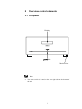
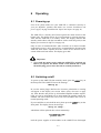
2
Overview control elements
2.1 Frontpanel
Display
AMP VII
Multichannel power amplifier
power
power key
Mains switch
Note
·
The mains switch is located at the front right side on the bottom of
the unit.
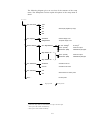
7
8
22
23
24
25
26
Balanced (XLR) input channel 1
Cinch input channel 1
Balanced (XLR) input channel 2
Cinch input channel 2
Balanced (XLR) input channel 3
Cinch input channel 3
Balanced (XLR) input channel 4
Cinch input channel 4
3
4
5
6
7
8
21
3
2
2
1
1
4
20
5
8
18
9
Speaker terminal channel 7
Speaker terminal channel 6
Speaker terminal channel 5
16
17
Cinch input channel 7
Balanced (XLR) input channel 7
Cinch input channel 6
Balanced (XLR) input channel 6
Cinch input channel 5
Balanced (XLR) input channel 5
19
7
15
14
13
12
11
10
9
6
10
17
16
13
14
15
Marking mains phase 2
Mains input 2
Audionet Link input
25
26
Mains input 1
Marking mains phase 1
Speaker terminal channel 1
Speaker terminal channel 2
Speaker terminal channel 3
Speaker terminal channel 4
12
24
23
22
21
20
19
18
11
3
Overview connections
3.1 Back panel
4
Installation and power supply
Important
·
For connecting or removing loudspeakers and/or the pre amplifier your AMP VII must be switched off to prevent damage to the
amplifier or the connected units.
·
Please make sure that all cables are in absolute best conditions!
Broken shields or short-cut loudspeaker cables could damage
speakers and/or amplifiers.
4.1 Placement
The compact design of the AMP VII requires the unobstructed heat dissipation during operation. Please mind the following security notes:
Important
·
Please find a place for your Audionet AMP VII that is sufficiently
ventilated to allow the heat to dissipate.
·
Do not cover the ventilation slots of the unit.
·
Please make sure that the microprocessor controlled fan units on the
bottom side of the AMP VII are able to intake cool air without any
obstruction. Particularly avoid placing the unit onto soft surfaces like
furry carpets or similar squashy materials the AMP VII might sink in.
·
We strongly advise you not to operate the AMP VII inside a confined
space, e.g. small cabinets.
·
Do not expose the unit to direct sunlight.
·
Do not place the AMP VII in close range to heat sources like radiators or fan heaters.
·
Due to the heavy weight of the AMP VII, please check the carrying
capacity of your rack or table before placing the unit onto it.
4.2 Mains connection
Both mains inputs 23 * and 25 are on the back panel of the AMP VII.
To connect the unit to mains use the included cords. If you prefer to use
different power cords make sure they meet the specifications for your
home country.
*
see numbers in section 'Back panel' on page 8
9
Important
·
Always use both mains connections.
·
The electrical specifications of your home country must meet the
electrical specifications printed onto the back panel.
·
The AMP VII is a Class I unit and must be earthed. Please ensure a
stable earth connection. Phase ('hot' pin) is marked 'phase' ( 22 and
24 ) on the back panel for each mains input.
·
If you connect the mains cords please make sure that the mains
switch on the bottom of the unit (see section 'Frontpanel' on page 7)
is switched off.
·
Never pull the mains plug(s) while the AMP VII is switched on! Before you pull the mains cord(s) off their sockets, power down the unit
to stand-by mode and switch off the mains switch on the bottom side.
Only in cases of extended absence (like vacations) or if massive trouble
on the mains power is to be expected you should switch off the AMP VII.
To disconnect the unit completely from mains pull both mains plugs.
Tipp
·
Using high-quality mains cords may improve the sound quality.
Please consult your local Audionet dealer.
4.3 Orientation of mains plug
The correct polarization of mains is important for reasons of audio clarity
and stability. Please connect the mains cord so that the hot pins of the
wall outlets are connected to the pin of the mains inputs 23 und 25
marked 'phase' 22 and 24 .
Note
·
Your Audionet AMP VII is able to detect a wrong polarization of
both mains plugs during start-up. When you switch on the unit from
stand-by mode using the power key on the front panel, the AMP VII
will issue the warning
Att.: Mainsphase
No.1 Incorrect!
if the mains plug to mains input mains1 23 has the wrong orientation and/or
Att.: Mainsphase
No.2 Incorrect!
10
if the mains plug to mains input mains2 25 has the wrong orientation. In this case please switch off the unit with the power key to
stand-by mode. Then disconnect it from mains with the mains switch
on the bottom side. Now, flip the mains plug with the wrong orientation in the wall outlet (see section 'Mains phase detection' on page
14).
5
Inputs and outputs
Important
·
For connecting or removing loudspeakers and/or the pre amplifier your AMP VII must be switched off to prevent damage to the
amplifier or the connected units.
·
Please make sure that all cables are in absolute best conditions!
Broken shields or short-cut loudspeaker cables could damage
speakers and/or amplifiers.
5.1 Inputs
At first, connect your pre amplifier to inputs 1 to 14 (depending on the
number of modules) of your AMP VII. For each channel (module) you
may choose to use Cinch or balanced (XLR) cables alternatively. For
cable lengths exceeding 10 m we recommend the use of balanced cables.
Important
·
Do not forget to select the inputs you are using in the setup menu (see
section 'Set Input' on page 21).
·
The input may be selected for each channel individually.
5.2 Speaker terminals
Now connect your speakers to the gold plated terminals 15 bis 21 on
the back panel of the AMP VII. You can use both banana plugs or spades
as well as simple cable ends.
11
Note
·
Look out for the correct connection of your speaker cables. Usually
the terminals of your speakers are marked '+' and '-'. The AMP VII
uses the same marks.
·
Wrong speaker polarization will result in severe loss of sound quality!
Important
·
Although the AMP VII has an effective protection system to prevent damage to the circuits, switch off the unit while working on
the speakers and/or audio cables.
·
The nominal loudspeaker impedance should be 2 Ohms or higher.
·
Never use force or tools tightening the terminal screws.
Tip
·
If your speakers support bi-wiring, use two separate cables to connect
each speaker to the AMP VII. Impulse response and spatiality my
improve significantly.
Note
·
Again, please mind the correct polarization of the speakers!
5.3 Audionet Link
For your convenience, the AMP VII can be controlled remotely by one of
Audionet's multichannel pre amplifiers (e.g. MAP or MAP 1) as well as
one of Audionet's stereo pre amplifiers (e.g. PRE or PRE 1) using the
'Audionet Link' interface.
You only need a simple optical 'Toslink' cable to connect the 'Audionet
Link' output of your Audionet pre amplifier to the 'Audionet Link' input
link IN 26 of the AMP VII.
12
6
Operating
6.1 Powering up
First of all, please make sure your AMP VII is connected correctly to
your pre amplifier, speakers and mains (see section 'Installation and
power supply' on page 9 und Section 'Inputs and outputs' on page 11).
The AMP VII is a stand-by unit. Please operate the mains switch on the
bottom side. The display shows for a brief moment a welcome message.
After that the AMP VII is in stand-by mode. The display indicates the
stand-by mode either with the text off or with a small dot (pixel) in the
display (see section 'Set Off-Text' on page 22).
Only in cases of extended absence (like vacations) or if massive trouble
on the mains power is to be expected it is recommended to disconnect the
AMP VII from mains. Operate the mains switch on the bottom side to
switch off the unit from mains. The display goes dark.
Important
·
Never pull the mains cord(s) while the AMP VII is switched on!
Before you operate the mains switch on the bottom side or pull
the mains plug, power down the unit to stand-by mode first.
6.2 Switching on/off
To power up the AMP VII from stand-by mode, press the power key on
the front panel. The AMP VII issues the message:
Waking up...
In case the mains plug(s) has/have the incorrect polarization a warning
will appear in the display (see section 'Mains phase detection' on page
14). After that the unit powers up all installed amplifier modules sequentially. As soon as all modules are up and running the speaker outputs are
enabled. The unit informs the user of all active channels and is now in
normal operating mode.
If you would like to switch off the unit, please press the power key on the
front panel. The display shows the message:
Going to sleep..,
which then will be replaced after a short moment by:
DISCHARGING NOW
please wait...
until the power supplies of all modules in the AMP VII are discharged
13
completely. The unit is now in stand-by mode, and the display shows the
selected stand-by text (see section 'Set Off-Text' on page 22).
Note
·
Please wait until the end of the discharging process, before you
switch on the AMP VII again by pressing the power key on the front
panel.
6.3 Mains phase detection
The correct polarization of mains is important for reasons of audio clarity
and stability. Please connect the mains cords that the 'hot' pin of the wall
outlet is connected to the pins marked 'phase' 22 and 24 of the mains
inputs 23 and 25 . The AMP VII recognizes the incorrect polarization
of the mains plug automatically. Right after switching on the unit from
stand-by mode by pressing the power key on the front panel the following message appears in the display in case mains input 23 has the wrong
polarization:
Att.: Mainsphase
No.1 Incorrect!
or in case mains input 25 has the wrong polarization:
Att.: Mainsphase
No.2 Incorrect!
If you read the above message(s), power down the unit by pressing the
power key. Please wait until the display no longer reads:
DISCHARGING NOW
please wait...
Disconnect the AMP VII from mains by operating the mains switch on
the bottom side. Now pull the mains plug(s) with the wrong polarization
and re-insert it/them rotated by 180°.
If you switch on the unit again, the warning(s) should not appear.
Important
·
If the AMP VII issues the polarization warning or no warning at all
for both positions of the mains plugs, check the connection to earth of
your mains sockets and mains cords. You have to ensure a stable
connection to earth for the mains phase detection of the AMP VII
to work correctly!
14
6.4 Using Audionet Link
If your AMP VII is connected to an Audionet pre amplifier via 'Audionet
Link', use the remote control of the pre amplifier to automatically switch
on/off the AMP VII (and all other units connected via 'Audionet Link').
For setting up the necessary connections please refer to section 'Audionet
Link' on page 12.
Note
·
Some Audionet units forward the 'switch on' signal over the Audionet
interface with a small delay to avoid all units switching on at the
same moment, which could cause an overload of your mains fuse.
Please consult the manual of your other Audionet units for further information.
·
Independently from the 'Audionet Link' interface, you can switch
on/off your AMP VII at any time using the power key on the front
panel.
6.5 AutoStart function
If the AutoStart function is active, the AMP VII starts up automatically to
normal operating mode and does not stay in stand-by mode right after the
unit is connected to mains power (e.g. by operating the mains switch on
the bottom side). Use this option to start up the AMP VII automatically
using a timer device. For further details please refer to section 'Set
AutoStart' on page 22.
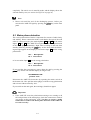
6.6 Warm Up countdown
While you are absent the AMP VII can switch on automatically after a
preselected time (15 minutes up to 99 hours and 45 minutes) and is then
preheated and ready for a listening session when you get back.
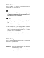
To setup the countdown clock press the power key on the front panel
longer than 2 seconds (= long keystroke) while the AMP VII is in standby mode. The display shows:
WARM UP IN :
01 hour 15 min
The cursor marks the digit of the countdown time to edit. A long keystroke moves the cursor one digit to the right.
Use short keystrokes (= press key less than 2 seconds) on the power key
to set the desired digit. Hours can be programmed in steps of 1 hour,
15
minutes in steps of 15 min. The following diagram explains the possible
countdown timer settings:
01 hour
15 min
01 hour
15 min
01 hour 15 min
11 hours 15 min
02 hours 15 min
01 hour 30 min
91 hours 15 min
00 hours 15 min
01 hour 00 min
10-hours setting
1-hour setting
minutes setting
long keystroke
short keystroke
Activate the countdown timer by leaving the timer setup menu with a
long keystroke. Alternatively, the countdown is started automatically if
you do not change any settings for longer than 12 seconds.
Note
·
While the countdown is running, the display shows the remaining
time until automatic start-up:
WARM UP IN :
02 hours 43 min
·
If the display saver is active, the display shows the remaining countdown time abbreviated (e.g. 02:43). Please refer to section 'Set Dim
Level' on page 20 for detailed information on the display saver.
If you would like to use the countdown timer again, simply activate it by
a long keystroke: While in stand-by mode press the power key longer
than 2 seconds and wait. After 12 seconds the countdown will start again
with the previous programmed time.
To de-activate a running countdown just press the power key for less
than 2 seconds at any time.
16
7
Protection system
Your Audionet AMP VII protects your loudspeakers and itself with a
complex protection circuitry. In case of a malfunction the display informs
the user about the nature of the detected error in plain text. Furthermore,
the unit also reports which module caused the error.
Example:
DC VOLTAGE IN:
Amp Module No. 5
This means a 'DC Voltage' error was detected in module no. 5.
The following table gives an overview of error messages:
Error message
Possible cause
Overload
short circuit or defective speaker
Overheating
ventilation slots covered
High Freq.
defective pre amplifier
DC Voltage
exceeding DC level at the output:
defective pre amplifier or source unit
Power Failure!
(temporary) breakdown of mains
Even after powering down the AMP VII, the error message will still be in
the display. Press the power key on the front panel to reset the display to
indicating the stand-by mode.
Note
·
Mains is monitored for all modules globally, so that in case of the
error Power Failure! no module number is displayed.
·
The error message Multiple Errors in Amp Modules! means
that multiple errors occurred simultaneously in different modules.
Important
·
Remove cause of error prior to switching on the AMP VII again!
17
8
Setup menu
Beyond the feature of the 'Warm Up Countdown' you can adjust the
AMP VII to your preferences using the setup menu.
List of settings adjustable according to your preferences:
· Brightness of display (Set Dim Level)
· Display mode (Set Display)
· Input selection (set indiviually for each amplifier module): Cinch or
balanced (Set Input)
· AutoStart function: automatic start for timer control (Set AutoStart)
· Selection of stand-by indicator (Set Off-Text)
Press the power key on the front panel longer than 2 seconds (= long
keystroke) to enter the setup menu. Use a short keystroke (= less then 2
seconds) to navigate to the next menu item.
Select a menu item with a long keystroke. Now you can select your desired option with short keystrokes.
To leave a menu item hold down the power key longer than 2 seconds or
simply wait longer than 12 seconds. If you would like to change more
settings please re-enter the setup menu.
While you are in the main menu, get back to normal operating mode by
waiting longer than 12 seconds or navigate to menu item Exit... and
select it.
Note
·
In case you stop editing any user settings the AMP VII leaves the
setup menu automatically after 12 seconds and returns to normal operating mode.
·
While you are in the setup menu the display brightness is adjusted to
100% for better readability. Leaving the setup menu resets the display brightness to the user selected level automatically.
·
If you power down the unit to stand-by mode, all user settings are
stored automatically in the non-volatile memory of the unit. Even after disconnecting from mains the AMP VII will still remember your
settings.
18
The following diagram gives an overview of the structure of the setup
menu. The subsequent sections explain all options of the setup menu in
detail.
Active
Set Dim Level
100%
75%
Select display brightness (5 steps)
50%
25%
OFF
Set Display
Select Module
Standard
Standard display mode
Temperature
Temperatur display mode
all Amp Modules
do not change1
No change2
Line (Cinch)
Select Cinch input2
Balanced (XLR)
Select balanced (XLR) input2
Line (Cinch)
Select Cinch input3
Balanced (XLR)
Select balanced (XLR) input3
Amp Module No. 1
Amp Module No. 7
Set AutoStart
Set Off-Text
disabled
AutoStart function off
active
AutoStart function active
off
Select indicator for stand-by mode
dot
Exit setup menu
Exit...
long keystroke
short keystroke
1
menu item is only visible, if not all modules are setup to the same input
2
select input for all modules simultaneously
3
select input for each module individually
19
8.1 Set Dim Level
Select the brightness of the display on the front panel. Five steps are
available: 100%, 75%, 50%, 25% and OFF.
Important
·
Long-term usage of the display set to a maximum brightness (setting 100%) may cause extended signs of wear resulting in a decay
of contrast or brightness of individual dots in the display. Do not
use the display with a brightness set higher than the factory default of 50% over a longer period of time!
Note
·
Is the brightness set to Off the display is only on during setup adjustmentes, powering up/down and while displaying an error message. It switches off automatically several seconds after the last user
entry.
·
The AMP VII activates the 'display saver' automatically after 10
minutes without any user entry.
·
While the 'display saver' is active, the display shows, depending on
the selected display mode (Set Display), either Active or the
temperature of the AMP VII in the form of Temp Cool/Ok/High.
The display brightness is automatically reduced to 25% , and the location of the information text changes randomly every 12 seconds to
prevent any 'burn-in' effect of the display.
·
The 'display saver' is de-activated, and the display retruns to its normal mode as soon as any user entry is detected.
·
The user cannot switch off the automatic 'display saver' function!
8.2 Set Display
Select the information the AMP VII displays while in normal operating
mode. There are two modes available:
Standard
The normal operating mode is indicated by:
Active
Multi-Channel In
Temperature During normal operating mode the AMP VII shows its
working temperature in 3 steps:
Cool
the AMP VII is cool,
Ok
the AMP VII has its normal operating temperature,
High
the AMP VII is working at a higher tempera
ture under heavy load.
20
Note
·
In case of thermal overload the AMP VII will always switch off independently from the display setting.
·
The temperature display mode gives the user a clue about the thermal
load of the AMP VII. It depends on the placement, air flow and cooling, surrounding temperature and the number of installed modules in
the AMP VII. Nevertheless, the full musical performance is achievd
even if the display reports Temperature Cool.
8.3 Set Input
The user can select the input for all modules simultaneously or individually. First, navigate to menu item Select Module and enter the sub
menu SET INPUT FOR with a long keystroke on the power key.
Now use short keystrokes to select the module whose input you would
like to configure:
all Amp Modules
Use this setting if you would like to configure
the input for all modules simultaneously. All
modules will be set to the same input after the
following configuration.
Amp Module No. x
Select the module whose input you would like
to configure individually. The input settings of
all other modules are not affected after the following configuration.
Acknowledge the module selection with a long keystroke of the power
key on the front panel. The AMP VII enters the sub menu Set Input.
Now select the desired input:
Line (Cinch)
Select this option if you connected your re amplifier
to the Cinch input of the module.
Balanced (XLR) Select this option if you connected your pre amplifier to the balanced (XLR) input of the module.
do not change
Select this option if you would like to exit the menu
without any change. This option is only available if
you selected all Amp Modules before and not all
modules are set to the same input.
21
Tip
Pinning of the balanced (XLR) inputs:
1: Ground
3: Negative
2: Positive
The pins are marked with the same number as in the diagram above.
8.4 Set AutoStart
If the AutoStart function is active, the AMP VII starts up automatically to
normal operating mode right after the unit is connected to mains power
(e.g. by operating the mains switch on the bottom side). Use this option to
start up the AMP VII automatically using a timer device.
disabled
The AutoStart function is disabled. If you connect the
AMP VII to mains power, the unit will start up to standby mode. To activate the AMP VII use the power key on
the front panel or the Audionet Link interface.
active
The AutoStart function is active. As soon as the AMP VII
is connected to mains power, the unit starts up to normal
operating mode automatically. Use this setting to control
the AMP VII by a timer device.
Note
·
In order to use the AutoStart function with a timer device, the mains
switch on the bottom side has to be in position 'on' all the time. The
connection to mains is switched by the timer device in this case.
8.5 Set Off-Text
Select here how the AMP VII indicates the stand-by mode:
off
Stand-by mode is indicated by the text off.
dot
Stand-by mode is indicated by a small dot (pixel) in the display.
22
Note
·
Approx. every 12 seconds the stand-by mode indicator changes position randomly in the display to prevent any 'burnin' effect (see section
'Set Dim Level' on page 20).
8.6 Overview factory defaults
Option
Einstellung
SET DIM LEVEL
50%
SET DISPLAY
Standard
SET INPUT
Line (Cinch)
SET AUTOSTART
disabled
SET OFF-TEXT
dot
Note
·
The Warm Up countdown is preset to 1 hour and 15 minutes, but deactivated (see section 'Warm Up countdown' on page 15).
23
9
Technical information
9.1 Design
To optimize the high frequency properties the circuitry was consequently
miniaturized and SMD technology implemented. Signal path ways are
limited to a minimum length and contain no componets harmful to the
quality of sound like coupling capacitors, coils or relays. The construction is optimized magnetically and capacitively. Influences of interferences and interaction between amplifier stages are extensively ruled out.
The signal cables are made of pure silver and gold metallurgy.
9.2 Circuitry
The input stage is designed as a double differential amplifier with a lownoise monolithic double-FET. The gain-bandwidth product of the input
stage is greater than 1 GHz. Double-boot-strapping decouples the input
from the power stage. The power stage consists of four PowerMOSFETs. A complex correction circuit locally compensates distortion
in real-time.
9.3 Power supply
Each amplifier module has its separate power supply with a toroid transformer with a power of 600 VA. Shottky rectifiers drive six high current
capacitors with a capacity of 49,200 mF for each channel resulting in a
total capacity of almost 345,000 mF for an AMP VII equipped with 7
channels.
9.4 Handling
The microprocessor controls all functions and constantly monitors DC
level, high frequency, temperature and overload and switches off the
AMP VII from mains in case an error is detected. The display issues error
messages in plain text. Automatic power on/off is provided via the
Audionet Link interface. User configurable inputs are switched by gold
plated high precision relays.
24
10
Security advice
Important
·
Avoid packaging material, especially plastic bags, coming into children's hands!
·
Store and operate the unit in a dry room at a reasonable room temperature only!
·
Avoid moisture, any liquids, dirt or small objects getting into the
unit!
·
Set up the unit in a sufficiently ventilated environment!
·
Do not cover the unit!
·
Do not open the unit. Unauthorised opening will void warranty!
·
Do not short-circuit the outputs!
·
During connecting or removing loudspeakers and/or the pre amplifier
your AMP VII must be switched off to prevent damage to the amplifier or the connected units.
·
Use dry cloth for cleaning!
We would like to wish you many exciting listening experiences with your
new Audionet product.
If you still have any questions, do not hesitate to ask your competent
Audionet dealer or contact us directly.
25
11 Technical data
Function
Modular microprocessor controlled
7-channel power amplifier
Power (per channel)
150 Watts in 8 Ohms
250 Watts in 4 Ohms
360 Watts in 2 Ohms
Frequency response
2 – 300.000 Hz (-3dB)
THD+N
> 107 dB @1 kHz (25 Watts / 4 Ohms)
SNR
> 122 dB (A weighted)
Inputs
1 Cinch, WBT, gold plated (per channel)
1 Balanced (XLR), Neutrik, gold plated (per channel)
1 Audionet Link, optical
Input impedance
Cinch: 37 kOhm, 150 pF
Balanced (XLR): 3 kOhm, 170pF
Outputs
1 pair of speaker terminals, gold plated (per channel)
1 Audionet-Link, optical
Mains
2 x 230 V, 50..60 Hz
Power consumption
5 Watts Stand by, 1200 Watts typ., 3500 Watts max.
Dimensions
Width:
Height:
Depth:
Weight
58 kg
430 mm
196 mm
430 mm
Front: brushed aluminium, 10 mm
black anodized, white print or
'aluminium nature' anodized, black print
Finish
Display: red or blue
Top: aluminium, black anodized, 6 mm
Sides: aluminium, black anodized, 4 mm
Chassis: steel, black coated
Features
-
microprocessor controlled protection system
-
automatic mains phase detection
-
2-lines vaccum fluorescent display
-
remote control via Audionet Link (optical)
-
timer function (Warm Up countdown)
-
AutoStart function for Timer control
Errors and omissions excepted. Specifications and design are subject to changes without prior notice.
26
audionet is a trademark of
Idektron GmbH & Co KG
Engineered and produced by:
Idektron GmbH & Co. KG, Herner Str. 299, Gebäude 6, 44809 Bochum, Germany
www.audionet.de
[email protected]
27