1
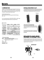
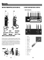
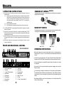
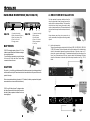
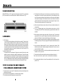
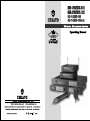
1.INTRODUCTION
INSTALLATION OF BELT-CLIP
Congratulation in owning one of these state-of-the-art PLL Synthesized 16 channels frequency
agile UHF high band ( SDR-1816/SDR-2816/SDR-2916/SDR-2932 ) professional wireless
receivers. According to their frequency range, these receivers are designed to match with Chiayo
UHF high band PLL Synthesized transmitters (handheld or beltpack).
This specially designed detachable belt-clip allows the user to wear the transmitter with antenna pointing upward or
downward as illustrated. To wear the transmitter with the transmitter pointing upward, install the belt-clip as in Fig.5.
To wear the transmitter with the antenna pointing downward, please install the belt-clip as in Fig,6.
Charging points
The standard combinations are as follow:
SDR-1816 / SDR-2816 / SDR-2916 / SDR-2932 matches SQ-816, SQ-916, SM-816plus or
SM-916 (UHF)
As this is a shared operating manual of SDR-2816/SDR-2916/SDR-2932, you MUST read this
operating manual thoroughly to familiarize with the function of each part before use.
Fig.5
System classification
Charging points
SDR-1816
Frequency Band
No. Of Channel
Receiving Type
Handheld Transmitter
Beltpack Transmitter
AC Adapter
Fig.6
SDR-2816
SDR-2916
SDR-2932
UHF
16
16
Diversity
16
16x2
Ture Diversity
SQ-816/SQ-916
SM-816PLUS or SM-916
10-15V / 800mA x 1 piece
12-15V / 800mA x 1 piece
Size
1/2 19"
INSTALLATION OF CABLE RESTRAINT
To prevent contact noise caused by constant tension applied to the connector,, a
cable restraint is designed such that tension is totally reduced when it is properly
used ( see Fig.7 ).
When the audio cable go through the cable restraint, it could prevent sweat from
going diectly into the electronic board via the connector. This is another advantage of
the cable restraint.
Fig.7
19"
Standard system packaging
SDR-1816 or SDR-2816 or SDR-2916 or SDR-2932
SDR-1816 /SDR-2816/SDR-2916 are shipped with one transmitter each.
SDR-2932 are shipped with 2 transmitter each.
Antenna
2 pieces
AC adaptor
1 piece
Rackmount bracket 2 pieces
Operating manual
1 copy
Receiver
Transmitter
INSTALLATION OF LAVALIER / HEADSET
MICROPHONES OR INSTRUMENT INPUTS
Depending on customer requirements, Lavalier / Headset microphone or instrument inputs could be
connected to the transmitter via the audio input connector. User is free to choose the various input
sources but is advised to take note that connector used must be compatible to each other. The pin
configurations for mini XLR connector is in Fig.8.
SWITCHCRAFT
LED INDICATOR
OFF
GT IN
ON
2
3 4 1
POWER
ANTENNA
MT IN
GND
POWER
SWITCH
Fig.8
PHANTOM POWER
1
10
BELT-PACK TRANSMITTER (SM-816PLUS/SM-916)
2.FRONT AND REAR PANEL CONTROL
SDR-1816/SDR-2816
1
2
3
4
7
A
ESS
B
T R A N S MI
9
11
15
3
T TE
8
13
5
R
W
EL
6 7
SDR-2816
POWER
IR
5
MIN
MAX
1
ON
9
INSTALLATION OF BATTERIES
SM-816plus uses 3 pieces of " AA " size batteries (Alkaline battery is recommended ). To install or
remove the batteries, press the release buttons at the edges of the transmitter to open or close the
cover as illustrated ( Fig.2 ). When installing the batteries with the cover open toward you, the
cover might block your hand. It is thus recommended that while inserting or removing the batteries
you should hold the transmitter in such a way that the cover open a way from you. ( Fig.3 )
SM-916 uses one piece 9V batteries, To install or remove the battery , press the release button at
the side edge of transmitter to open or close the cover as . ( Fig.4 )
Fig.3
10
RF SIGNAL LEVEL
DIVERSITY
11
1.
Power switch
2.
Power on indicator
3.
RF signal indicator
4.
Diversity indicator
5.
AF signal indicator
6.
RF test button
7.
Channel selector
8.
Volume control
9.
Antenna B socket
10.
XLR ( balanced ) audio output
11.
Unbalanced audio output
12.
Squelch ( SQ ) control.
13.
D C IN jack
14.
Antenna A socket
12
Fig.2
9 13
AF SIGNAL LEVEL
2
RF-TEST
CHANNEL
13
VOLUME
14
3.OPERATING INSTRUCTIONS
CHANGING OF CAPSULE (SQ-916)
3.1
Before switching on the receiver, please make sure that the following are observed and
installed properly:
3.1.1 Frequency group shown at the frequency stickers of transmitter and receiver MUST
be the same. If it is a brand new set and the matching is incorrect, kindly return the
system to your Chiayo dealer in exchange for a new set. If it is not a new set, you
must have taken the wrong combination. Please DO NOT try to operate any
unmatched system.
3.1.2 The two antennas must be installed.
3.1.3 The AC adapter must have the same voltage rating as that of your power outlet.
These microphone have a module design. To change or replace a capsule, Open the grill to pull out and plug in the
capsule as shown in the following figure.
3.2
For SDR-1816/SDR-2816. Channel selected at Receiver Must be the same as the channel
selected at Transmitter
SENSITIVITY SWITCH
3.3
Now switch on the transmitter (please refer to transmitter operating manual). The RF
indicator will light up when the correct channel is selected, indicating that the radio signal
transmitted has been received.
Use RF test button to test if there is interference around. If there is interference around, the
RF signal level LED will light up. The receiver is suggested to switch to another frequency
to use.
When sound is spoken into the microphone, the audio indicator will flash to show the
strength of the audio level.
3.4
3.5
FRONT AND REAR PANEL CONTROL
1
2
3 4
5
6 7 8
VOLUME
11
SENS
H
N
H
High Sensitivity
OPERATING INSTRUCTIONS
Before operation, please check and make sure that transmitter & receiver are of matching frequency or
frequency group (for PLL version). For PLL version, further verify that the channel selected at both ends are of
the same.
PLL TRUE DIVERSITY RECEIVER
10
SENS
N
Low Sensitivity
SDR-2916/SDR-2932
9
These microphone have a sensitiving switch, For close mouth singing or normal speech please put the switch to
N (normal) position. For tripod-mount speech, please put the switch to H (high) position.
12
13
14
VOLUME
Fig.4
15
To switch on the microphone, put the switch to "ON" position. The green LED indicator will light on indicates
that battery is fresh. When RED LED light on indicates that battery is weak, thus a replacement is necessary.
For best result, alkaline battery is recommended. Please remove the battery if the transmitter is not to be used
for a longer period.
1.
2.
3.
4.
5.
6.
7.
8.
Slot for front mount antenna
Power switch
7 - segment LED channel indicator
Channel selector
Diversity indicator
RF signal indicator
AF signal indicator
RF test button
9.
10.
11.
12.
13.
14.
15.
3
Volume control
Antenna socket
XLR balanced output
Unbalanced output
Squelch ( SQ ) control
DC IN jack
AC IN jack ( for certain market only ).
Fig.5
When necessary, SQ-916 mic capsule could be replaced by pulling out and plugging in the new one, either
dynamic or condenser.
For close mouth singing or speaking, put the sensitivity switch to N (Normal) and for tripod mouth application,
where the speaker stands at a distance away, put the sensitivity switch to H (High). Be careful to put back the
sensitivity switch to N for close mouth singing as H (High) sensitivity for close mouth application might cause
distortion.
When holding the handheld mic, please do not hold the antenna part of it as this might severely affect the
efficiency of the transmission range.
8
4. RECEIVER INSTALLATION
HAND-HELD MICROPHONE( SQ-816/SQ-916)
1
SQ-816
2
3
1.
2.
3.
4.
5.
4
5
1
Capsule with metal grill
Battery Good indicator ( Green )
Battery Low indicator ( Red )
Power on / off switch
Charging contacts
BATTERIES
SQ-816 This microphone requires 3 pieces of " AA " size
batteries to operate. Please insert the batteries according to
the correct polarity indicated.
To open the battery compartment, press and slide down
the cover until it clicks and lockes. Further sliding
movement will remove the cover.
2
SQ-916
3
4
5
1.
2.
3.
4.
5.
6.
6
Capsule with metal grill
Battery indicator
Sensitivity switch
Power on / off switch
Battery compartment
Color Cap
SQ-816
For best operation, the receiver should be at least 1m
above the ground and at least 1m away from a wall or
metal surface to minimize reflections. The transmitter
should also be at least 1m away from a wall or metal
surface to minimize reflections. The transmitter should
also be at least 1m away from the receiver, as shown in
Fig. 5
Keep antennas away from noise source such as
motors, automobiles, neon light as well as large metal
objects.
Fig.5
4.1 Audio output connection
There are two audio outputs on the back of the Diversity SDR-1816 / SDR-2816 / SDR-2916
/ SDR-2932 receivers. Mic-level balanced and Line-level unbalanced. Use shielded audio
cable for the connection between the receiver and the mixer. If the mixer / amp is a 1/4"
phone jack, connect a cable from the 1/4" unbalanced audio output from the receiver to the
mixer / amp. If the mixer has an XLR input, connect a cable from the balanced XLR audio
output from the receiver to the mixer input. Audio output connection is as Fig.6 , 7& 8,9
below.
CAUTION
Fig.7
The positive ( + ) pole of battery must face downward. Many batteries are known to have leakage problem of
conductive and corrosive liquid. Please observe the rule to remove the batteries if they are not to be used for
a period of a few days.
Fig.6
Due to various unstandardized sizes ( diameters ) of " AA " batteries, this battery compartment is designed to
accommodate the most commom Alkaline batteries only.
SQ-916 use a 9V battery for power. To change or replace
the battery. Please remove the color cap first, then press at
the bottom of battery compartment to release the cover as
shown in right figure.
Fig.8
Pre
ss
SQ-916
7
Fig.9
4
5.RACK MOUNTING
SDR-1816/SDR-2816 are 1/2 19" casing and specially designed (optional) 19" rack mount adapters
(MP-50) are available for your installation purposes. Installation instructions are as Fig. 10.
4 If the Volume Control of the receiver is set too high, it may over-drive the input of the mixer,
causing distortion. Conversely, if the receiver output is set too low, the overall signal to noise
ratio of the system may be reduced. Adjust the output level of the receiver such that highest
sound pressure level going into the microphone causes no input overload in the mixer, and
yet permits the mixer level controls to operate in their normal range (not too high or too low ).
This provides the optimum signal to noise for the entire system.
5
6
Fig.10
7
6.REMARKS
5.1 RF Interference
If you encounter receiving interference (from other than an operating TV station), often it
can be overcome by adjusting the receiver's squelch control, as described on 5.2 below.
Please note that wireless frequencies are shared with other radio services. According to
FCC requlations, wireless microphone operations are unprotected from interference from
other licensed operations in the band. If any interference is received by any Government or
non-Government operation, the wireless microphone must cease operation. The
abovestatement is valid in the U.S.A.
5.2 Receiver Squelch control
The squelch control on the back panel of the receiver is preset at the factory, but can be
adjusted if you must use the system in a high RF interference area. If there is audio output
from the receiver when your transmitter is OFF, adjust the squelch control so the system will
receive the signal from your transmitter but squelch or eliminate the unwanted background
RF noise. This adjustment can cause a reduction in usable range of the wireless transmitter,
so set the control to the lowest position which reliably mutes the unwanted RF signal.
8
Before inserting the batteries, please make sure that they are inserted according to the
correct polarity.
For PLL 16 frequencies agile version, before operation please make sure that the
corresponding receiver MUST have the same frequency group and channel number as the
transmitter.
Before making any channel change, please switch off the power supply. The synthesized
program works in such a way that a change of channel will only take place after a power off
and on action. Otherwise, the previosly selected frequency will stay unchanged.
After making a channel change, please make sure that the corresponding change is made on
the matching receiver also. To be exact, changes MUST be made at both the transmitter and
receiver.
9
Use only brand new Alkaline batteries. Do not use " general purpose " batteries. When
batteries are weak, replace the batteries altogether at the same time. Do not mix and use
new and old batteries together.
10 Position the receiver such that it has the least possible obstructions between it and the
transmitter. Line of sight is best!
11 The transmitter and the receiver should be as close as possible but not less than 1m.
12 A receiver cannot receive signals from two or more transmitters simultaneously.
13
Turn the transmitter off when it is not in use. Remove the batteries if it is not to be used for a
period of time.
7.TIPS TO OBTAIN THE BEST RESULTS
FOR A WIRELESS MICROPHONE SYSTEM
1 If external antenna is used, low loss RF shielded cable should be used and the length of the
cable should not exceed 3m.
2 Do not place the receive antenna within 1 m of another receiver or antenna.
3 The receiver antenna should be kept away from any metal surface.
5
6