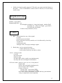
1
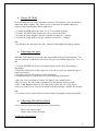
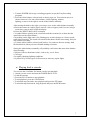
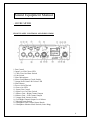
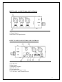
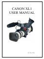
CANON XL1
USER MANUAL
By Lindsey Thorpe
1
Canon XL1 Manual
• Mounting and removing XL lenses
Mounting
1. Remove the dust cap from the lens and the body cap from the camcorder.
2. Align the red dot on the camera body with the mount positioning point (the red dot)
on the lens, then turn the lens clockwise until it clicks and locks into place.
Removing
1. Slide and hold the LENS RELEASE switch and turn the lens counter-clockwise
until it stops. Then, remove the lens from the camera body.
2. When you are not using the lens or camera, be sure to replace the dust cap and body
cap.
Attaching the lens hood
1. Remove the lens cap.
2. Align the hood with the lens lengthways, and the Canon logo facing to the left.
3. Twist it 90° into position (clockwise), so that the Canon logo is to the top.
• You do not need to assert any pressure — screw the hood lightly into place.
4. Finally, tighten the locking screw.
• To remove, reverse the above procedure.
• Attaching the studio microphone
1. Loosen the microphone attachment screw on the viewfinder unit and insert the
microphone into the microphone clamp.
2. Align the mark on the microphone with the mark on the clamp and tighten the
screw to hold the microphone firmly in place.
3. Plug the microphone cable to the camera’s MIC terminals.
NB: Make sure that the camera is turned off before attaching or removing the
microphone cable.
2
• Loading and unloading a cassette
1. Make sure that you have inserted a power source.
2. Slide the EJECT button across to release the cover.
• Wait a couple of seconds for the cassette compartment to open automatically.
3. Load or unload the cassette.
• Insert the cassette gently with the window facing out.
• Remove the cassette by pulling it straight out.
4. Press the mark on the compartment until it clicks.
5. Click the cover back into place.
• Selecting from the menus
1. Turn the POWER dial to a recording program or to VCR.
2. Slide open the red cover to reveal the menu operation keys.
3. Press the MENU button to open the menu.
4. Press r or t cursor key to move the arrow up or down the display.
5. Press the e cursor key to select your chosen option from the menu.
• Your selected option remains on the screen and all other options are removed.
6. Press the r or t cursor keys to choose its setting.
• You can return to the full menu by pressing the e cursor key.
7. Press the MENU button to close the menu.
• Close the red cover to hide the menu operation keys.
Menu:
Zebra (shows if too much light is hitting the camera)
16: 9 (off)
Movie mode – normal (movement is smooth)
Frame (not as smooth, better for a sunrise shot)
Sensor (on)
Tally lamp (record lamp which indicates that the camera is recording)
Audio mode: 16 bit (2 channels) – if you use the front mic, lose back sound
12 bit ST-1 (4 channels) – can use front mic, radio mic, lappelle mic
but poorer quality
12 bit ST-1-2
Audio 1 in
line
Mic att 20 – pump up level if low or chop off level if high
Audio 2 in
(if set at 12 ST-1-2 can change settings but sacrifice quality)
Rec mode
SP (short play)
LP (long play) – extends tape usage
D/time set
does not have to be visible. Indicates when the shot was taken
3
• Using the various recoding programmes
The camera provides you with a choice of six recording programs. They use different
combinations of camera settings in order to adjust the exposure and other functions to
match the recording situation.
The name of your selected recording program appears constantly on the left of the
display, with the exception of the Easy Recording program whose mark is displayed
and then disappears after 4 seconds.
Easy recording
The simplest way to use the camera is with the POWER dial set to the position. The
camera will take care of focus, exposure and other adjustments, leaving you free to
point and shoot.
Auto
In normal recording conditions, set the POWER dial to (Auto). This is the same as the
Easy Recording program, except that you now have the option of using any of the
camera’s manual functions — you can adjust focus and exposure, set the white
balance, and so on.
Manual
Select this program for total creative freedom when operating the camcorder. You can
set aperture and shutter speeds completely independently to give you exactly the
exposure you require.
Giving priority to shutter speed (Tv)
Use this program to let you select the shutter speed.
The camera sets the appropriate aperture (F number) automatically to give the correct
exposure. When you turn the POWER dial to Tv, the current shutter speed is shown in
the viewfinder. Select your desired shutter speed by pressing the SHUTTER and other
buttons.
You can choose 9 shutter speeds between 1/60 and 1/15,000 of a second.
• If you try to set a shutter speed that is either too high or too low for the shooting
conditions, the indicator flashes in the viewfinder. In this case, increase or decrease
the setting until the flashing stops, or slide the ND FILTER switch ON/OFF as
appropriate before changing the setting.
4
Giving priority to the aperture (Av)
Use this program to let you select the aperture (iris diameter) to give you maximum
control over the depth of field. A large F number (a small aperture) gives a greater
depth of field.
Av F2.8
Use this program to let you select the shutter speed. The camera sets the appropriate
aperture (F number) automatically to give the correct exposure. When you turn the
POWER dial to Tv, the current shutter speed is shown in the viewfinder. Select your
desired shutter speed by pressing the SHUTTER and other buttons.
You can choose 9 shutter speeds between 1/60 and 1/15,000 of a second.
• If you try to set a shutter speed that is either too high or too low for the shooting
conditions, the indicator flashes in the viewfinder. In this case, increase or decrease
the setting until the flashing stops, or slide the ND FILTER switch ON/OFF as
appropriate before changing the setting.
NB:
The camera memorizes the latest Tv or Av value until a new value is set.
Turning off the camcorder or changing the recording program does not erase the
stored value.
Adjusting the focus
Temporary focus override
You can adjust the focus temporarily without turning autofocus off. Turn the lens’s
focusing ring to set the focus. Autofocus will resume as soon as you take your hand
away from the focusing ring.
Manual focus
1. Slide the focus switch on the body of the
XL lens to M (manual).
2. When using a zoom lens, rotate the zooming ring to the telephoto end.
3. Rotate the focusing ring to adjust the focus.
4. When using a zoom lens, use the zooming ring to reframe the subject.
• To resume autofocus, slide the focus switch to AF (auto).
• If you focus manually then leave the camcorder with the power turned on, you may
lose focus on your subject. This possible slight shift in focus is due to a rise in
temperature in the camcorder interior and lens. Check the focus before resuming
shooting
5
• Using AE Shift
By controlling the level of the automatic exposure (AE) function, you can lighten or
darken the image slightly. This allows you to compensate for backlit subjects or
subjects with predominately dark or light tones.
1. Turn the POWER dial to the Auto, Tv or Av recording program.
2. Turn the AE SHIFT dial to adjust the AE to your desired level.
• To make the image brighter, turn the controller towards the + settings.
• To make the image darker, turn the controller towards the – settings.
NB:
• AE shift does not function in the Easy, Manual or Spotlight Recording programs.
• Adjusting the gain
When the GAIN knob is set to (auto) the camera adjusts the gain automatically. You
can also rotate the GAIN dial to one of the five preset levels that range from –3 to +12
dB.
1. Turn the POWER dial to any recording program except (Easy Recording) or
(Spotlight).
2. Press the GAIN knob so that it pops out. You can now turn it to adjust the gain to
your desired level.
• The gain level you select appears in the viewfinder.
• Push the knob back in when you have finished making adjustments.
-3dB: Low noise recording for indoor, low light or low contrast scenes.
0dB: Low noise, life-like colour reproduction of illuminated scenes at night.
+6dB/+12dB: Brighten indoor or low-light scenes (when the iris is fully open).
Gain-up to enable you to increase the depth of field from using a smaller iris aperture.
NB:
• You cannot use the GAIN in the Easy Recording or Spotlight recording programs.
• Adjusting the white balance
The XL1 has two modes other than fully auto (A) and manual:
-
Indoor mode (3200°K light)
Outdoor mode (5600°K sunlight)
Setting the white balance
6
1. Turn the POWER dial to any recording program (except the Easy Recording
program).
2. Press the white balance selector knob so that it pops out. You can now turn it to
choose between A for auto white balance, indoor lighting, outdoor
lighting, or turn it to the right to set the white balance manually.
After turning the knob to the right, you can go on to set the white balance manually:
a) Point the camera at a white object (such as a sheet of paper) and if you are using a
zoom lens, zoom in until it fills the display.
b) Press the WHITE BALANCE set button.
• A symbol flashes quickly in the viewfinder and then remains lit, to show that the
camera has set the white balance.
• Depending on the light source, the flashing may at times change to a slower speed,
rather than remain lit. The result will remain better than with the auto setting, and you
can continue recording.
c) Turn the white balance selector knob back to A to return to the auto setting. Push
the knob back in when you have finished making selections.
Setting the white balance manually will probably work better than auto white balance
when shooting:
• Subjects with one dominant colour, such as sky, sea or forest.
• Close-ups.
• In rapidly changing lighting conditions.
• In places lit by certain types of fluorescent or mercury vapour lights.
• Playing back a cassette
You can use the viewfinder for instant, on-the-spot playback.
1. Attach a power source and turn the POWER dial to VCR.
2. Load the cassette.
3. Press the PLAY button to start playback.
• To end playback, press the STOP button.
• To wind the tape forwards, stop playback and press the FF button.
• To wind the tape backwards, stop playback and press the REW button.
7
Sound Equipment Manual
- SHURE MIXER
FRONT PANEL CONTROLS AND INDICATORS
1. Pan Control
2. Input Level Bi-Colour LED
3. 1 kHz Tone Oscillator Switch
4. Link Switch
5. Slate Microphone
6. Meter Lamp/Battery Check Switch
7. Output Peak/Limiter Bi-Colour LED
8. Slate Button
9. Power On/Off Switch
10. Power On LED
11. Input Gain Control
12. Input Low-Cut Filter Switch
13. Master Gain—Right Channel Output
14. Master Gain—Left Channel Output
15. Output Peak Limiter Switch
16. Left/Right Channel Output Level Meters
17. Monitor Input Switch
18. Headphone Gain Control (Inner Knob)
19. Headphone Monitor Mode Switch (Outer Ring)
8
INPUT PANEL CONNECTORS AND CONTROLS
1. Channel Inputs:
2. Mic/Line Level Input Switch:
OUTPUT PANEL CONNECTORS AND CONTROLS
1. Mix Bus Jack
2. Main Output
3. Headphones Outputs
4. Monitor In Jack
5. Tape Output Jack
6. Mic/Line Level Output Switch
7. 12–30 Vdc In Jack (External Power)
9
Rifle mic – put yellow cable (Female) into Male. Insert the opposite end of the yellow
cable into the Shure Mixer. Turn Shure Mixer on.
Plug headphones in by inserting the big jac.
Use channel 1, turn channels 2 and 3 down in order to avoid a hissing sound.
To check tone, turn tone button on, use the master switch to set it to -4. Insert green
plug into Shure mixer and the camera which must be set to 12.
If the green lights flashes red, the levels are too high.
Lappelle mic – The end of one side of the plug is inserted into the lapelle mic and the
other end into the Shure mixer.
Radio mic – There is a transmitter and a receiver. Ensure that the transmitter is
plugged into the Shure mixer while the receiver is plugged into the camera.
Wireless mic - that the frequency on the transmitter and the camera are the same.
Pulse Code Modulation (PCM):
Sound waves:
sound is recorded as 0 and 1 after it is converted
in pulse codes. The digital audio code (a series
of "off or on" signals) is recorded by the drum,
on a part of the tape that is separate from the
video information.
are vibrations in the air. There are 2 basic properties:
frequency and amplitude. Frequency – from low to
high, Amplitude – from soft to loud. Together they form
a sine wave. The wave’s amplitude is represented by its
height; the further the curve swings above and below its
centre line, the louder the signal. Its frequency can be
represented by the number of times per second the wave
goes through a complete "cycle". The more cycles per
second, the higher the wave’s frequency.
What does the microphone do?
The microphone picks up sound and outputs an analogue signal. This signal is then
passed through an analogue-to-digital (A/D) converter.
An analogue signal that ranges between +1 and -1 volts goes through an infinite range
of values between those points, but a digital system can record only a finite number of
those values. The more digits it has, the more steps it can distinguish and the more
closely it can match its readings to the variations in the original signal. Because
digital systems use finite means to record infinite signal variations, some mismatch is
inevitable, and every such mismatch adds noise and distortion to the signal.
10
16-bit stereo = highest quality sound, produces CD quality sound, 2 channel sound on
one track
12-bit stereo (2 channels) = records on 2 of the 4 available channels, leaving the other
channels available for the addition of sound, music, narration, etc.
12-bit stereo (4 channels) = used for simultaneous recording on four channels which
means audio can be outputted as four independent channels. Audio quality is slightly
lower.
XLR Microphones: balanced, contain a noise-cancelling cable that greatly reduces
unwanted interference
Locked and unlocked audio: unlocked = always completely in sync with the video.
The difference is found with the number of audio samples per video frame. Locked –
the sample rate per frame of video is fixed, while with unlocked audio allows for
some slight variations in the number of samples per frame.
Terminals vs Tracks : Audio 1 and Audio 2 refer to the physical location of the
audio inputs. Audio 1 terminals appear on the back of the camcorder, Audio 2
terminals are on the right side of the handle. Stereo 1 and Stereo 2 refer to the stereo
tracks available on the tape.
Audio Monitor: only use when using 12-bit (Stereo 1 and 2) mode. If you use the 16bit mode, then the sound is fixed in Stereo 1 only.
Camera Recording: You can select the sound source you want to record: Stereo 1, 2
or a mix of both
Selecting the audio output in VCR Playback Mode: When playing back a tape in
which the audio was recorded in 12 bit (Stereo 1, 2) mode, you can select the output
you would like to hear. Press the audio monitor button to cycle through these 4
selections: Stereo 1, 2, Default mix, variable mix
If the sound was recorded in 16 bit mode, it only contains Stereo 1 sound and you
cannot select an audio mix
Choosing the output channel
Make sure the camera is set to VCR mode. Open the menu and select the output
channel you wish:
L/R (Stereo) = default
Normal stereo mode – left-side signal + output at left channel terminal + the right-side
signal + output at right channel terminal
Audio mode 16 bit/12 bit stereo 1, audio signal will be sent to RCA jacks labelled
L&R
11
Stereo 1 for output at Stage A, Stereo 1 (L&R) will be sent to RCA jacks labelled
Audio 2 (L&R) & Stereo 2 (L&R) – RCA jacks labelled Audio 2 (L&R) = 4
independent audio signals
Mixed the balance at Stage A, combination of left channels from stereo 1&2 sent to
left channel of Audio 1 & combination of right channels will be sent to right channel
of Audio 1.
L/L
Only left side signal is output to RCA left & right jacks. For reproducing only main
voice of bilingual information recorded on other equipment.
R/R
Only the right side is output to the RCA left & right jacks. For reproducing only sub
voice of bilingual information on other equipment
L+R+R
Gives a mono output. Sound from the left and right channels are combined and sent to
the left RCA jacks.
Audio Input for Two Channel Recording (Stereo 1) using the mini jacks, where the
sound source is the supplied microphone or an external microphone plugged into the
mini jacks (3.5mm mini-plug type):
1. Open the Camera Menu.
Select AUDIO MODE. Choose one of the following modes:
a. 16-bit 48kHz 2 channel (for the highest sound quality). Note: the 16-bit
mode contains only Stereo 1 sound. There is no Stereo 2 in this mode.
b. 12-bit Stereo 1 (32kHz, 2 out of 4 total channels) for recording on 2
channels (Stereo 1), leaving 2 channels (Stereo 2) free for you to add
new sound at a later date using a DV VCR. NOTE: you cannot add
new sound to a tape using the XL1 camcorder.
Close the menu. The name of your chosen mode is displayed in the viewfinder
and main LCD panel. It is not necessary to set AUDIO 1 to MIC on the menu.
2. Slide the INPUT SELECT switch to MIC.
This assigns the MIC mini jacks as the source for the audio input. You can use
the supplied microphone or attach an external microphone, or slide the INPUT
SELECT switch to ATT. If you are recording in a very loud environment (at
an airport for example), you may want to use the attenuator. The attenuator
reduces loud noises to produce a more natural sound.
3. Select the recording level method.
12
Normally, the camera sets the audio recording level automatically, as long as
the REC LEVEL switch is set to A. You can set the recording level manually:
a. Slide the REC LEVEL switch of the AUDIO 1/Mic controls to M.
(MANU appears in the audio LCD panel).
b. Turn the LEVEL dial to adjust the recording level and BALANCE dial
to adjust the balance between the 2 inputs. Check the levels in the
audio LCD panel. Note: you can not adjust the volume level
independently for the left and right channels. We recommend keeping
the level below the 12 point index mark, and monitoring the sound
using headphones. You can adjust the headphone volume by rotating
the PHONES LEVEL dial.
Audio 1 Input for Two Channel Recording (Stereo 1) using the RCA jacks, where
the sound source is a VCR, CD or other input device using the RCA terminals on the
back of the XL1, instead of the microphone mini jack.
1. Open the Camera Menu.
Select AUDIO MODE and choose one of the following modes:
a. 16-bit 48KHz 2 channel (for the highest sound quality) Note: the 16-bit
mode contains only Stereo 1 sound. There is no Stereo 2 in this mode.
b. 12-bit Stereo 1 (32kHz, 2 out of 4 total channels) for recording on 2
channels (Stereo 1), leaving 2 channels (Stereo 2) free for you to add
new sound at a later date using a DV VCR. NOTE: you cannot add
new sound to a tape using the XL1 camcorder.
Close the menu. The name of your chosen mode is displayed in the viewfinder
and main LCD panel. It is not necessary to set AUDIO 1 to MIC on the menu.
2. Slide the INPUT SELECT switch to AUDIO 1. This assigns the AUDIO 1
RCA jacks as the source for the audio input.
3. Open the Camera Menu and select AUDIO 1 INPUT, then choose LINE to
record sound from a VCR, CD or other line-in devices.
4. Select the recording level method.
Normally, the camera sets the audio recording level automatically, as long as
the REC LEVEL switch is set to A. You can set the recording level manually:
a. Slide the REC LEVEL switch of the AUDIO 1/Mic controls to M.
(MANU appears in the audio LCD panel).
13
b. Turn the LEVEL dial to adjust the recording level and BALANCE dial
to adjust the balance between the two inputs. Check the levels in the
audio LCD panel. Note: you cannot adjust the volume level
independently for the left and right channels. We recommend keeping
the level below the 12 point index mark, and monitoring the sound
using headphones. You can adjust the headphone volume by rotating
the PHONES LEVEL dial.
Audio 1 Input for Two Channel Recording (Stereo 1) using the RCA jacks, where
the sound sources are XLR type microphones attached via the MA-100 Microphone
Adapter/Shoulder Pad which contains 2 XLR inputs (L and R). The MA-100 can be
plugged into the AUDIO 1 RCA terminals on the back of the camcorder, or AUDIO 2
RCA terminals on the right side of the grip handle.
1. Open the Camera Menu.
Select AUDIO MODE and choose one of the following modes:
a. 16-bit 48KHz 2 channel (for the highest sound quality) Note: the 16-bit
mode contains only Stereo 1 sound. There is no Stereo 2 in this mode.
b. 12-bit Stereo 1 (32kHz, 2 out of 4 total channels) for recording on 2
channels (Stereo 1), leaving 2 channels (Stereo 2) free for you to add
new sound at a later date using a DV VCR. NOTE: you cannot add
new sound to a tape using the XL1 camcorder.
Close the menu. Chosen mode is displayed in the finder and main LCD.
2. If you are using the AUDIO 1 inputs, slide the INPUT SELECT switch to
AUDIO 1. This assigns the AUDIO 1 RCA jacks (on the back of the XL1) as
the source for the audio input, and disables the supplied microphone.
3. Open the Camera Menu and select AUDIO 1 INPUT, then choose:
a. MIC ATT 20: recording high-level sound using a mic
b. MIC: to record sound using an XLR microphone
4. Select the recording level method. Normally, the camera sets the audio
recording level automatically, as long as the REC LEVEL switch is set to A
(automatic). You can set the recording level manually:
a. Slide the REC LEVEL switch of the AUDIO 1/Mic controls to M.
(MANU appears in the audio LCD panel).
14
b. Turn the LEVEL dial to adjust the recording level and BALANCE dial
to adjust the balance between the 2 inputs. Check the levels in the
audio LCD panel. Note: you can not adjust he volume level
independently for the left and right channels. We recommend keeping
the level below the 12 point index mark, and monitoring the sound
using headphones. You can adjust the headphone volume by rotating
the PHONES LEVEL dial.
Audio Input for Four Channel Recording (Stereo 1 and Stereo 2, simultaneous
recording of all four channels) using the RCA jacks, where the sound sources are the
supplied microphone; external microphones; VCR, CD or other line-in devices; or
using XLR type microphones.
Four channel recording can be the most versatile configuration. For example, you can
input two external wireless microphones and use the supplied microphone, all
simultaneously.
1. Open the Camera Menu and select AUDIO MODE.
Select 12-bit ST-1, 2 and close the menu. "12bit ST-1,2" is displayed in the
viewfinder and main LCD panel. Selecting Audio Mode 12-bit ST-1,2
(32kHz, 4 channels) is for simultaneous recording on four channels (referred
to as Stereo 1 and Stereo 2).
2. To set the input for Stereo 1:
Use the supplied mic or external microphone plugged into the mini jacks.
Slide the INPUT SELECT switch to MIC. This assigns the MIC mini jacks as
the source for the audio input. In place of the supplied microphone, you can
attach an external microphone to the mini jacks.
or
Slide the INPUT SELECT switch to ATT. If you are recording in a very loud
environment, you may want to use the attenuator. The attenuator reduces loud
noises to produce a more natural sound.
or
Use the Audio 1 RCA jacks on the back of the camcorder to record sound
from a VCR, CD or other line-in devices; or XLR microphones. Switch the
Input Selector to Audio 1. Open the Camera Menu and select the appropriate
option for AUDIO 1 IN:
a. LINE: to record sound from a VCR, CD or other line-in devices
b. MIC ATT20: to record high-level sound using a microphone
c. MIC: to record sound using an XLR microphone attached to the MA100 Microphone Adapter/Shoulder Pad.
15
3. To set the input for Stereo 2:
Connect a device to the AUDIO 2 RCA jacks on the handle.3 From the
Camera Menu, select Audio 2 INPUT, then select the appropriate option for
AUDIO 2 IN:
a. LINE: To record sound from a VCR, CD or other line-in devices
b. MIC ATT20: To record high-level sound using a microphone
c. MIC: To record sound using a XLR microphone attached to the MA100 Microphone Adapter/Shoulder Pad.
4. Select the recording level for 4 channel recording.
Normally, the camera sets the audio recording level automatically, as long as
the REC LEVEL switch is set to A (automatic). You can set the recording
level manually:
a. Set the recording level for Stereo 1:
Slide the REC LEVEL switch of the AUDIO 1/MIC controls to M.
Turn the LEVEL dial to adjust the recording level and BALANCE dial
to adjust the balance between the two inputs. Check the levels in the
audio LCD panel.
b. Set the recording level for Stereo 2:
Slide the REC LEVEL switch of the AUDIO 2 controls to M (manual).
c. Turn the L and R dials to independently adjust the recording levels of
the two inputs (corresponding to the L and R channels of the Audio 2
RCA jacks).
Check the levels for each channel in the audio LCD panel. It is
essential for you to monitor the sound using headphones. Adjust the
headphone volume by rotating the PHONES LEVEL dial.
Making a Sound Check while recording 4 channel audio:
Press the AUDIO MONITOR button to make a sound check — Stereo 1 only (ST1),
Stereo 2 only (ST2) or both (MIX), each in turn.
•
Your choice is selected a few seconds after you last pressed the button, and
shown in the viewfinder and audio LCD panel.
16
•
Unlike selecting the audio output in VCR mode, you cannot mix the balance at
this point — even if VARIABLE is chosen at the VCR menu, it is fixed during
camera mode.
Depth of Field
Shallow vs great DOF
Manipulating DOF = iris
Focal length (zooming in) - long focal length = shallow DOF
(zooming out) – short focal length = great DOF =
all in the same focal plane
Camera to object distance (focus)
Cables
1. BNC - only designed to carry video signals
- co-axial
- insulated protected sheath
- doesn’t generate electricity outside, nor is it influenced by electricity
outside of it
- professional cable
- analogue cable, carrying an analogue signal
2. Kettle plug - carries current/electricity
- controls behaviour of devices
- carries only electricity, not audio or video
3. RCA - analogue cable
- co-axial
- not professional
- domestic plug
- can take either video or audio, not simultaneously
- can only take one wavelength of information
4. Firewire cable - aka 4 to 6, 4 to 4, 6 to 6, 1394 protocol
- digital cable
- carries video and audio simultaneously
- only need one cable to digitise
- 2 types of firewire:
Firewire 400 = slower than USB2
Firewire 800 = same speed as USB2
- also carries control information, can start and stop your machine
using a complicated control algorithm
17
5. S-video cable – aka YC cable
- calculates values/changes by different algorithm
- between composite and component
- inside camera kit
- cleaner than composite
- video only
PATHWAYS: Composite – noisy, slow, analogue, only takes video information
Component – only video, no audio capacity
6. 9 pin Remote cable – allows to stop/start/record/eject
- no audio or video
- aka RSS control cable protocol
7. XLR (audio) – 3 plugs: i. neutral
ii. left
iii. right
- can take stereo
- audio only
8. Jack cable – stereo – indicated by black rings (on top and middle)
9. Network cable – telecommunications plug
Codecs/ Compression
Types of compression:
Video codecs can use spatial compression, temporal compression, or a combination of
both.
1. Spatial compression, affects only a single frame at a time. This type of compression
makes random access to any point in the video and editing easy. Spatial compression
finds redundancy within a frame—either in areas of flat or similar colours, or areas of
a frame that look like other areas of the frame—and saves space by encoding these
similar areas by reference, rather than by a literal description of colour attributes for
each and every pixel.
2. Temporal compression, adds the ability to use other frames as a reference for the
current frame. In video, each frame tends to be similar to the frame preceding it.
Temporal compression encodes only the changes from one frame to another (with the
exception of key frames, as described below, which contain a complete representation
of the data in a frame, without reference to previous frames).
18
Frame types and compression
You can reveal many fundamental concepts of compression by looking at the kinds of
frames in a file. Depending on the codec and options used, one, two, or three kinds of
frames may be in a file. A key frame, or I-frame, is a complete image that is
compressed using intraframe compression. An I-frame isn’t based on any other frames
in the file. The first frame of a movie is always an I-frame. A delta frame is
compressed using interframe compression and contains only those portions of the
adjacent frames that are different. If two frames are mathematically identical, and the
second one is a delta frame, it will require only a few bits to encode. But if more than
half of the image is different, most codecs automatically generate a new I-frame. For
typical content, a delta frame might be only 10-20% the size of the same frame at the
same quality as an I-frame.
There are two main types of delta frames: P-frames and B-frames. The content of a Pframe (predictive frame) is based on the previous frame; the content of a B-frame (bidirectional frame) is based on the previous and subsequent frames.
Audio compression
While audio may use only a small fraction of the bits in a compressed file, it is
responsible for half of the experience.
Sampling rate
The most fundamental factor in audio is sampling rate, which is measured in Hertz
(Hz), or cycles per second. Audio CDs use 44100 Hz, or 44.1 kilohertz (KHz), which
provides excellent reproduction.
Sample
Used
Sufficient for
8 KHz
Phone system
Speech
11 KHz
Old multimedia standard
Better speech
22.050 KHz
Also old multimedia standard
Recognizable music
32 KHz
Common in broadband video
Minimum for decent music
44.1 KHz
Audio CD
Music
48 KHz
DVD, DAT
Music
96 KHz
High-end audio recording
Music mastering
Bit depth
Bit depth is the number of bits used for each sample in each channel—the higher the
bit depth, the better the audio quality.
• 8-bit sampling This bit depth, which was responsible for that harsh sound in the
early CD-ROM titles, produces fairly poor quality audio. There is no reason to
19
distribute 8-bit audio anymore. Modern 16-bit codecs provide better quality at a
smaller file size than 8-bit codecs were ever able to.
• 16-bit sampling This bit depth is the current standard for audio distribution. Most
modern codecs and all audio CDs use 16-bit sampling as well.
• 20-bit sampling This bit depth is used for professional audio recording to provide a
better dynamic range than 16 bits. Codecs that support 24-bit audio can effectively
take advantage of 20-bit sources.
• 24-bit sampling This bit depth is rapidly becoming the standard for professional
audio recording because it provides more sonic detail than 16-bit sampling, meaning
you can use many more effects and layers without introducing errors.
Channels
Most audio from computers is either mono with a single channel or stereo with two
channels. Low bit rates generally use mono because it requires fewer bits.
There are techniques you can use to produce video that compresses well:
• Camera motion The amount and type of camera motion has a huge effect on the
compressibility of content. Camera motion changes every pixel of every frame.
Lack of camera motion is the simplest, of course. But modern codecs can encode
camera motion, such as that created using dollies, quite well. Tilts and pans are
more difficult. Depending on the codec, rotating the camera (a Dutch) can be trivial
or extremely costly in compression efficiency. The most difficult motion for any
codec is hand-held camera motion with random jostling.
• Shutter speed This speed controls how long the aperture is open in the camera, and
hence, how long light hits the film or the CCD. Slower shutter speeds let through
more light, and hence less grain, which helps compression. Slower shutter speeds
also cause moving parts of the image to become blurry, which makes them easier to
compress.
• Backgrounds A difficult motion for codecs is foliage rustling in the breeze. Foliage
is green, which makes up the majority of luma and therefore gets allocated many
bits in the compression. Leaves have hard, irregularly shaped edges, and details that
require many bits to encode well. Additionally, the motion of foliage in the breeze is
largely random, with leaves constantly overlapping and revealing, all motions that
are very difficult for motion estimation to handle.
• Depth of field A useful and subtle technique for controlling the complexity of
images is depth of field. By managing the depth of field, you can keep unimportant
objects in the background or close foreground out of focus while clearly showing
the actual subject of the shot. Depth of field is very common in cinematography and
photography, so it looks natural to the audience.
20
There are other techniques which can have as much effect on compressibility as the
above mentioned techniques. Because these techniques occur later in the process, it is
often possible to adjust them based on the results of test compressions, making finetuning much easier.
• Static versus moving images As in production, superfluous moving images aren’t
appropriate for content that you plan to aggressively compress. They are not that
important for DVD, but they are for web and CD-ROM.
• Motion blur In the same way that a real-world shutter speed introduces motion blur
that helps compression, you can use the virtual shutter in rendering applications. For
effects that support motion blur, render them with a shutter speed that matches that
of the source. This speed might be expressed as a duration, or, as in After Effects, as
the angle of a virtual shutter. The default is 180°, which corresponds to a shutter
speed half that of the frame rate.
• Anti-aliasing This rendering technique softens the edges of rendered elements,
letting a pixel at the edge of an area be an intermediate value. Smoothing out
transitions among parts of the image improves compressibility and appearance.
Capturing video: choosing formats and connections
• Analogue formats Analogue video uses fluctuating voltage and frequency signals to
transmit image data. It ranges greatly in quality but is inherently susceptible to
visual interference from electronic noise, like power lines, and suffers attenuation,
or the loss of signal power and quality over long cable runs (usually 300 meters or
more). Equipment that supports analogue signals is generally more affordable, and
analogue video formats are still the most commonly used because of the long-term
use of legacy equipment that is still active today.
Because computers only use digital data, the analogue source must be converted to a
digital copy to be captured. When it is sent back to an analogue medium like
videotape, it is converted back to an analogue signal. This conversion can lead to
minor errors (quantization errors) being introduced because of the imprecise
relationship between analogue and digital signals. You can minimize these
quantization errors by using the right format, good equipment, cables, and
connections.
• Composite A composite video signal carries the luminance and the chrominance
channels in a single signal. The biggest problem with composite video is that luma
information can leak into chroma, and vice versa. This leakage can lead to noise,
known as chroma crawl, which can be amplified by the video capture process and
reduce the overall quality. Composite video is generally understood to be the lowest
quality video signal that you can use and is more appropriate for video delivery
(broadcast) than as a source for content creation (video editing, DVD authoring, or
encoding for the web). Common sources of composite video are VHS (1/2 inch
tape) VCRs and camcorders, broadcast television signals, and older U-Matic 3/4inch professional VTRs.
The connectors common to composite video are RCA or Cinch for consumer
equipment and BNC (Bayonet Neill-Concelman), a twist-locking connector
21
common to professional and broadcast video equipment. As the quality of the RCA
or BNC cable that is used increases, the noise and attenuation decreases.
• S-Video The introduction of the S-Video format was a major advance in quality for
consumer and professional video editors. S-Video splits the luma and chroma
channels into two separate wire pairs, which eliminates generally half of the
composite noise artefacts. The two chroma channels are still combined and still
interfere with each other, leaving some noise in the signal.
• Component analogue With component analogue, also known as YUV (Y for
luminance, U for one chroma channel, and V for the other chroma channel) the
luminance signal and the two colour signals are all transmitted over their own
dedicated cables. Because all three components or channels of the video signal are
transmitted independently, the quality of the signal is quite high. Noise is very low
and the colours in the video are richer and more precise.
• Unbalanced audio This type of audio connection consists of a single wire that
carries the signal, surrounded by a grounded shield. It is used commonly in
consumer audio products because the connection and circuitry are less complex. The
downside is that unbalanced connections are more susceptible to interference, so
they are not often used in professional applications.
There are three basic kinds of unbalanced audio connectors. The most familiar to
consumers is traditional unbalanced audio that uses RCA or Cinch jacks (normally
red for right and white or black for left). To connect a stereo signal, you can use a
single RCA cable for each channel, or a stereo cable that has two single cables
moulded into one.
• Balanced audio This type of connection consists of two wires, which serve to
balance the signal, and a shield. A balanced connection is far less susceptible to
interference, so it is possible to maintain high quality with long cable runs. Balanced
audio normally uses the XLR, or three-pin, locking connector, which provides a
much tighter and robust connection than the connectors used for unbalanced audio.
Digital formats
DV formats the original video signal on tape using digital data similar to that used by
computers. Multiple digital formats are available in the video industry.
• DV25 (DV) This format is most commonly known by the physical connection
standard it uses, IEEE-1394 or FireWire, however it uses only a fraction of the data
rate and speed available in the IEEE-1394 connection standard.
• SDI(Serial Digital Interface) SDI is a high-end, professional format for digital
signals. The SDI format, technically known as CCIR-601 or 601, is superior in
quality to component analogue video and is the standard in professional and
22
broadcast television. Because it is digital and uncompressed, it can be edited and
copied many times with no detectable loss of quality.
• Digital audio There are many different digital audio formats. Consumer-grade
digital audio is carried on electronic (such as S/PDIF) or optical (such as square
TOSlink or round Miniplug) connection cables. Digital video carries an embedded
digital audio signal with the digital video signal.
Choosing the right capture codec
When you capture content, you must choose an appropriate codec. The choice
depends on the capture hardware you’re using, the format from which you’re
capturing, and your storage requirements. There are three basic types of codecs to
choose from: DV, Motion JPEG, and uncompressed.
1. DV codecs
The DV25 format is ideal when capturing from a DV25 deck. Over a FireWire
connector, you can use DV25 to copy the native bits from the tape onto a hard disk,
making a perfect copy. If you use a different format at a higher data rate, the resulting
video will be slightly lousy.
2. Motion JPEG codecs
Motion JPEG has been the leading format for high-end video-editing systems for
some time. Motion JPEG is 4:2:2, and most implementations allow you to specify a
data rate or quality level.
3. Uncompressed codecs
More and more cards support true 4:2:2 uncompressed video. The data rates are large,
and the quality is no better than a lossless compression. One significant advantage of
some uncompressed codecs is support for 10-bit-per-channel captures, which can
perform better for analogue and especially SDI sources.
Exporting video
Capturing from tape is required for many projects, but for some projects, all content is
created electronically. In other projects, a lot of creative work is done during editing
and compositing on the computer. In those cases, going back out to tape is an
unneeded distraction. Many tools, such as After Effects and Adobe Premiere Pro can
export to a compressed file from the timeline, a process that works well for a single
file. However, if features in other encoding tools are required, for example, volume
encoding to multiple output formats, it is useful to export an intermediate from the
timeline and use the exported file for further processing.
Exporting to file
A file you export for later processing is called an intermediate file. The goal of
creating an intermediate file is to provide high quality in the most useful format
without introducing any compression artefacts.
23
Choosing whether to preprocess or to avoid rendering
The first question that you should ask is when to apply preprocessing (described in the
next section): during the rendering phase or later. Preprocessing during rendering
generally results in a smaller file, but adds more rendering time. It also means you
can’t use an encoding tool for special operations, like inverse telecine.
Basically, to avoid rendering, you use the same codec and file format as your source
video. If you don’t preprocess, you don’t need to uncompress and then recompress
unmodified frames—instead, you copy them from the source into the output.
Different tools support this process in different ways—in Adobe Premiere Pro, you
turn off the Recompress option in the Video pane of the Export Movie Settings dialog
box. For this process to work, the video must truly be unchanged with the same frame
rate, frame size, pixel aspect ratio, and so on. The simplest way to ensure that no
changes were made to the video is to use the same project preset for export that was
used for import, which is the default behaviour in Adobe Premiere Pro.
When you preprocess, choose the highest frame rate and largest frame size that you
will use.
Choosing a file format for rendering
You can choose from a variety of file formats for rendering. The most common
formats are QuickTime and AVI; both offer good-quality intermediate codecs. You
can also use MPEG-2 at high data rates. Modern tools like After Effects and Adobe
Premiere Pro can export to Windows Media 9 format. It is essential to make sure that
the encoding tool supports the file format.
Choosing a codec for exporting
When you export an intermediate file, pick a codec and a data rate that doesn’t
introduce compression artefacts. When you are not preprocessing, it’s typical to use
the source codec or Motion JPEG. When you use Motion JPEG, use it in single field
when you export as progressive scan, or interlaced when you export as interlaced.
For AVI files on Windows, the Huffyuv codec is quite popular.
Deinterlacing video
The most basic and critical form of preprocessing for the web is deinterlacing. Most
video is produced and edited as interlaced (although, an increasing amount is done as
progressive scan). But almost all web video is encoded as progressive scan. If the
source frame of video is left with interlaced lines intact, the output shows the stacked
lines. The lines look bad, but worse, those lines have sharp edges and are difficult to
encode. So, at the same bit rate, deinterlaced video shows fewer artefacts than
interlaced video.
Cropping
Cropping is excluding areas of the source frame from inclusion in the output frame.
Content composed for video normally confines critical elements to what are called
24
safe areas. The safe areas exclude the edges of the screen, which may be cut off or
distorted on some televisions (especially older ones).
In some digital video editing applications, you can crop an image using a filter. In
others, such as After Effects, the easiest way to crop an image is to scale the video up
so the unwanted edges are no longer part of the frame. If you want an asymmetric
scale, you can move the anchor point of the video as needed.
An example of scaling is going from 720 pixels wide source to 352 pixels wide output
for VideoCD. The specified method for this scaling is to crop eight pixels from the
left and right of the source, leaving a 704 pixel wide frame that you can reduce by
exactly 50% to 352 pixels wide.
Scaling
Scaling is resizing the cropped source rectangle to the proper output frame size, for
example, going from a 720 x 480 source frame to a 320 x 240 output frame for web
video.
Scaling up on either axis forces a video editing application to make up data that’s not
in the source. It’s always preferable to scale down on both axes if possible.
Noise reduction
Noise reduction encompasses a variety of techniques to remove noise, especially
grain, from an image, making it easier to compress. Very simple noise reduction
algorithms are just blurs—they can hide grain, but can make the image quite soft as
well. The commonly used Median filter is a good blur for noise reduction. More
advanced algorithms try to blur only the parts of the image that have grain and may
take advantage of differences among frames.
Tools such as After Effects Professional perform automatic or manually-assisted
scratch removal and other processes to improve or repair degraded source. Normally
these tools are stand-alone applications or plug-ins to a video tool that need to be used
early in the workflow.
END OF MANUAL
25