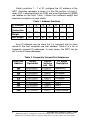
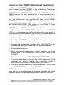
1
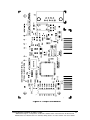
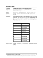
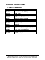
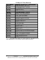
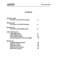
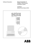
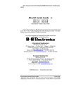
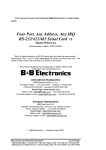
PC Watchdog Timer Card CE Models: ATRWDT and ATXWDT Documentation Number ATxWDT-1303 This product designed and manufactured in Ottawa, Illinois USA of domestic and imported parts by International Headquarters B&B Electronics Mfg. Co. Inc. 707 Dayton Road -- P.O. Box 1040 -- Ottawa, IL 61350 USA Phone (815) 433-5100 -- General Fax (815) 433-5105 Home Page: www.bb-elec.com Sales e-mail: [email protected] -- Fax (815) 433-5109 Technical Support e-mail: [email protected] -- Fax (815) 433-5104 European Headquarters B&B Electronics Ltd. Westlink Commercial Park, Oranmore, Co. Galway, Ireland Phone +353 91-792444 -- Fax +353 91-792445 Home Page: www.bb-europe.com Sales e-mail: [email protected] Technical Support e-mail: [email protected] B&B Electronics -- Revised March 2003 Documentation Number ATxWDT-1303 ATRWDT & ATXWDT Cover Page B&B Electronics Mfg Co – 707 Dayton Rd - PO Box 1040 - Ottawa IL 61350 - Ph 815-433-5100 - Fax 815-433-5104 B&B Electronics Ltd – Westlink Comm. Pk – Oranmore, Galway, Ireland – Ph +353 91-792444 – Fax +353 91-792445 Table of Contents CHAPTER 1: GENERAL INFORMATION...................................1 INTRODUCTION ..................................................................................1 FEATURES..........................................................................................1 SPECIFICATIONS ................................................................................1 CHAPTER 2: SETUP AND INSTALLATION...............................2 INSPECTION .......................................................................................2 ADDRESS SWITCH SETUP ..................................................................2 RELAY SETUP ....................................................................................5 INSTALLATION...................................................................................5 CONNECTING THE ATRWDT MOTHERBOARD RESET OPTION .........6 CONNECTING THE ATX RESET OPTION FOR THE ATXWDT ............7 INSTALLING THE SOFTWARE .............................................................7 CHAPTER 3: OPERATION .............................................................9 COMMUNICATING WITH THE WDT....................................................9 PINOUTS ..........................................................................................10 CHAPTER 4: SOFTWARE ........................................................... 13 WINDOWS NT AND WINDOWS 95 ...................................................13 Changing the I/O Port Address ..................................................14 Disk Caching ..............................................................................14 Existing DOS Programs .............................................................14 WINDOWS 3.11................................................................................14 Changing the I/O Port Address ..................................................15 Disk Caching ..............................................................................15 COMMAND REFERENCE ...................................................................16 BBPCWDT_Startup....................................................................16 BBPCWDT_Shutdown................................................................16 BBPCWDT_Reset .......................................................................17 BBPCWDT_ReadRegister ..........................................................18 APPENDIX A: HARDWARE I/O MAPS................................... A-1 APPENDIX B: QUICKBASIC EXAMPLE................................ B-1 APPENDIX C: DECLARATION OF CONFORMITY ............ C-1 Documentation Number ATxWDT-1303 Table of Contents B&B Electronics Mfg Co – 707 Dayton Rd - PO Box 1040 - Ottawa IL 61350 - Ph 815-433-5100 - Fax 815-433-5104 B&B Electronics Ltd – Westlink Comm. Pk – Oranmore, Galway, Ireland – Ph +353 91-792444 – Fax +353 91-792445 i Chapter 1: GENERAL INFORMATION Introduction B&B Electronics' Watchdog Timer (WDT) Cards, Models ATRWDT and ATXWDT, are hardware devices designed to overcome the dangers or annoyances associated with a PC "locking up." Your software periodically resets the WDT. If the watchdog doesn't receive the reset trigger within a software selectable timeout period, the WDT resets the computer. The ATRWDT uses the reset pins from the motherboard to reset the computer, where as the ATXWDT uses the ATX power supply to turn off the computer then turn it back on 10 seconds later. A form C relay output is also provided on both models to reset an external device if desired. This relay may be set to energize when the timeout is reached, or energize during normal operations. Features • • • Software selectable timeout period from 0.5 to 512 seconds Software enable and disable Form C relay output to control external device • Write back timeout verification • • Reset flag for ATRWDT Non-splicing connection to motherboard reset pins for the ATRWDT Non-splicing connection to the ATX power supply for the ATXWDT • Specifications Dimensions: 2.6" H x 4.1" L Address: 0 to 3F8h Power Consumption: 1.75 W maximum Output specs: Form C relay output, maximum ratings 24 VDC at 1.0 A 115 VAC at 0.5 A Connector: DB-9 male Documentation Number ATxWDT-1303 B&B Electronics Mfg Co – 707 Dayton Rd - PO Box 1040 - Ottawa IL 61350 - Ph 815-433-5100 - Fax 815-433-5104 B&B Electronics Ltd – Westlink Comm. Pk – Oranmore, Galway, Ireland – Ph +353 91-792444 – Fax +353 91-792445 1 Chapter 2: SETUP AND INSTALLATION Inspection Your WDT has been tested for proper operation. It should be in perfect electrical and mechanical condition upon receipt. Remove the card from its protective packaging. Handle the card only by its edges being careful not to touch the gold connection fingers. Save the packaging for storage or shipping if the card needs repair. Address Switch Setup The WDT can be set for any I/O address using a seven position DIP switch to program the binary I/O address of the card. Figure 1 is a drawing of the printed circuit board showing the locations of the address switch and setup jumpers on the WDT. 2 Documentation Number ATxWDT-1303 B&B Electronics Mfg Co – 707 Dayton Rd - PO Box 1040 - Ottawa IL 61350 - Ph 815-433-5100 - Fax 815-433-5104 B&B Electronics Ltd – Westlink Comm. Pk – Oranmore, Galway, Ireland – Ph +353 91-792444 – Fax +353 91-792445 Figure 1. ATRWDT/ATXWDT PCB Silk Screen Documentation Number ATxWDT-1303 B&B Electronics Mfg Co – 707 Dayton Rd - PO Box 1040 - Ottawa IL 61350 - Ph 815-433-5100 - Fax 815-433-5104 B&B Electronics Ltd – Westlink Comm. Pk – Oranmore, Galway, Ireland – Ph +353 91-792444 – Fax +353 91-792445 3 Switch positions 1 - 7 of S1 configure the I/O address of the WDT. Switches represent a binary 0 in the ON position, a binary 1 when OFF. Least significant bit (LSB) and most significant bit (MSB) are labeled on the card. Table 1 shows the numerical weight and electrical connection of each switch. Table 1. Address Switches S1 Position Bus Connection Decimal Weight Hex Weight 7 SA9 6 SA8 5 SA7 4 3 SA6 SA5 512 256 128 64 200 100 80 40 2 SA4 1 SA3 32 16 8 20 10 8 Any I/O address may be used, but it is important that no other device in the host computer use that address. Table 2 is a list of frequently unused I/O addresses. In most cases, the WDT can be set to one of these addresses. Table 2. Frequently Unused Port Addresses Base Hex Address Binary Equivalent Switch Settings MSB 200 208 300 308 310 318 380 388 3A0 3A8 4 1000000000 1000001000 1100000000 1100001000 1100010000 1100011000 1110000000 1110001000 1110100000 1110101000 I/O Space Description LSB 1000000 1000001 1100000 1100001 1100010 1100011 1110000 1110001 1110100 1110101 game port game port prototype prototype prototype prototype SDLC SDLC bisync comm bisync comm Documentation Number ATxWDT-1303 B&B Electronics Mfg Co – 707 Dayton Rd - PO Box 1040 - Ottawa IL 61350 - Ph 815-433-5100 - Fax 815-433-5104 B&B Electronics Ltd – Westlink Comm. Pk – Oranmore, Galway, Ireland – Ph +353 91-792444 – Fax +353 91-792445 If you want to install at another address, use the following procedure. 1. Select the address: Using an I/O port usage table (one is included in Appendix A) select an unused hex address space. Note that the WDT card occupies 8 bytes of I/O space. Use caution when selecting a port address, it is important that nothing else is installed at the selected address. 2. Convert the hex address to its binary equivalent. 3. Throw away the 3 least significant bits. 4. The remaining 7 digits represent the switch address. 1's represent an OFF switch. 0's represent an ON switch. Relay Setup The jumper labeled RELAY NORMALLY provides two ways for the external reset to be configured. With the jumper in the 0 position, the relay will normally be discharged, and will energize after the timeout is reached. In the 1 position, the relay will be energized while the timer is running. The relay will discharge after the timeout is reached, the timer disabled, or the power is turned off. Installation 1. Turn the power to your computer off and unplug from the power outlet. 2. Remove the cover of the computer. 3. Pick an unused ISA slot. The WDT will work in a short (8-bit) or full length (16-bit) slot. 4. Remove the expansion ISA slot cover. Save the screw for installation of WDT. 5. Install the WDT into the unused ISA slot. Be certain that the card is inserted completely into the slot. 6. Secure the card with the mounting screw. Documentation Number ATxWDT-1303 B&B Electronics Mfg Co – 707 Dayton Rd - PO Box 1040 - Ottawa IL 61350 - Ph 815-433-5100 - Fax 815-433-5104 B&B Electronics Ltd – Westlink Comm. Pk – Oranmore, Galway, Ireland – Ph +353 91-792444 – Fax +353 91-792445 5 Connecting the ATRWDT Motherboard Reset Option To use the ATRWDT to reboot the host computer, a connection must be made from the ATRWDT to the motherboard. The jumper wire supplied with the ATRWDT must be connected between the MOTHEBOARD RESET PINS jumper on the ATRWDT and the RESET pins on the host motherboard. If your computer has a RESET switch, the switch's jumper wires should already be connected to the motherboard reset pins. Remove the switch wires from the motherboard pins and connect them to the RESET BUTTON jumper on the ATRWDT. Next connect the jumper wire to the motherboard-reset pins. The other end is connected to the MOTHERBOARD RESET PINS jumper on the ATRWDT. These pins are in parallel with RESET BUTTON jumper and will allow the ATRWDT or your RESET switch to reboot the host computer. The polarity of the RESET JMPR is indicated on the ATRWDT PCB but, in most cases, not on the motherboard or reset switch. If you are unsure of how to connect the ATRWDT to the motherboard, use the following procedure to verify the polarity of the connections. 1. Disconnect the reset switch wires from the motherboard. 2. Install the ATRWDT in an empty ISA slot in your computer. Leave the computer cover off. 3. Connect the jumper wire provided with the ATRWDT to the motherboard-reset pins. Leave the other end unconnected. 4. Power up the computer. 5. After the computer has booted, connect the other end of the jumper wire to MOTHERBOARD RESET PINS jumper of the ATRWDT. 6. Remove the wires from MOTHERBOARD RESET PINS jumper. 7. If your computer does not reboot, the polarity was correct. If the computer did reboot, reverse the connection made to MOTHERBOARD RESET PINS jumper of the ATRWDT. 8. Follow the same procedure to connect the RESET switch wires to RESET BUTTON jumper of the ATRWDT. NOTE: Use caution when operating the computer with the case open. Be sure to ground yourself by touching the metal case of the computer before you handle any components inside the machine. 6 Documentation Number ATxWDT-1303 B&B Electronics Mfg Co – 707 Dayton Rd - PO Box 1040 - Ottawa IL 61350 - Ph 815-433-5100 - Fax 815-433-5104 B&B Electronics Ltd – Westlink Comm. Pk – Oranmore, Galway, Ireland – Ph +353 91-792444 – Fax +353 91-792445 Connecting the ATX Reset Option for the ATXWDT The ATXWDT uses the ATX Power supply to reset the computer. The ATXWDT sends a 5 volt, 10 second signal on the PS-ON data line to turn off the computer for 10 seconds. Then when this signal goes back to zero the computer turns back on. The ATX daughter board also allows the computer to bypass the ON/OFF button. Setting the jumper to ON/OFF will allow the ON/OFF button to work as normal. Setting the jumper to ALWAYS ON will bypass the ON/OFF button, leaving the computer always on. 1. Unplug the computer from the outlet socket. 2. Press the release tab on the connector to disconnect the power cable from the motherboard. 3. Set the Jumper to ON/OFF or ALWAYS ON. 4. Plug the 20-pin connector of the jumper wire into the motherboard’s power connector. 5. Plug the 3-pin connector of the jumper wire into ATX CONNECTOR jumper of the ATXWDT. 6. Plug the power cable into the header on the jumper wire. Installing the Software The software provided with the WDT is only for Windows. If you are not using Windows, you do not need to install the software. 1. Insert the floppy disk in drive A: 2. Run the setup program. This step is different depending on the version of Windows: A. For Windows 3.11, select RUN from the FILE MENU of the Program Manager and type: A:\SETUP.EXE B. For Window 95 or Windows NT, select SETTINGS | CONTROL PANEL | ADD/REMOVE PROGRAMS from the Start Button and type A:\SETUP.EXE 3. Follow the directions in the setup program to complete the installation of the software. After the software is installed, the file, FILES.LST, contains a list and description of the installed files. The file, HISTORY.LST, Documentation Number ATxWDT-1303 B&B Electronics Mfg Co – 707 Dayton Rd - PO Box 1040 - Ottawa IL 61350 - Ph 815-433-5100 - Fax 815-433-5104 B&B Electronics Ltd – Westlink Comm. Pk – Oranmore, Galway, Ireland – Ph +353 91-792444 – Fax +353 91-792445 7 contains a historic description of the product. The file, READ.ME, contains corrections and additions to the printed user’s manual. 8 Documentation Number ATxWDT-1303 B&B Electronics Mfg Co – 707 Dayton Rd - PO Box 1040 - Ottawa IL 61350 - Ph 815-433-5100 - Fax 815-433-5104 B&B Electronics Ltd – Westlink Comm. Pk – Oranmore, Galway, Ireland – Ph +353 91-792444 – Fax +353 91-792445 Chapter 3: OPERATION Communicating with the WDT The WDT uses a four-bit latch to start and stop the timers and set the timeout period. Regardless of the mode of operation of the WDT, a "1" must be written to the least significant bit of the latch to start the timers. Writing a "0" to the least significant bit of the latch at any time will stop the timers. Note that since the least significant bit is used to start and stop the counters, any even number written to the latch will result in the counters being turned off. The remaining three bits of the latch are used to select one of eight timeout periods. Table 3 shows the possible timeouts. Table 3. WDT Timeouts Binary Latch Value 0001 0011 0101 0111 1001 1011 1101 1111 Hex Latch Value 1 3 5 7 9 B D F Approximate Timeout (seconds) 0.5 2 6 14 30 126 254 510 To use the WDT from your program, the latch value corresponding to the desired timeout must be periodically written to the latch. After the counters are started, they are reset every time the WDT is addressed. As long as the WDT is addressed before the end of the selected timeout period, no reset will occur. To do this from a BASIC program, place an OUT <WDT address>, <latch value> somewhere in a reoccurring loop. Each time the OUT statement is executed, the WDT counters are reset and begin counting again. To disable the WDT, place an OUT <WDT address>, <0> in your program. Be certain that this statement is executed whenever your program is terminated. Documentation Number ATxWDT-1303 B&B Electronics Mfg Co – 707 Dayton Rd - PO Box 1040 - Ottawa IL 61350 - Ph 815-433-5100 - Fax 815-433-5104 B&B Electronics Ltd – Westlink Comm. Pk – Oranmore, Galway, Ireland – Ph +353 91-792444 – Fax +353 91-792445 9 The four bit latch values are also readable. Reading these bits is recommended to verify the presence and setup of the WDT. The BASIC command INP <WDTaddress> is used to read from the WDT. The top three bits are not used and can be masked out. In the ATRWDT the fifth bit is the reset flag. It will be a 1 when the ATRWDT resets the computer and a 0 if the computer has not been reset by the ATRWDT. This bit will be cleared if the computer is turned off or after the bit has been read. A small example program, written in QuickBASIC can be found in Appendix B. Table 4. Registers Write Register L0 L1 L2 L3 X X X X Read Register L0 L1 L2 L3 Reset Flag FOR ATR X FOR ATX X X X X = Don’t Care Pinouts Three pins of the male DB-9 connector are used for the WDT. Pins 4 and 7 are the external device reset relay contacts. These are non-polarized, normally open contacts, and pins 3 and 7 are for the normally closed. Figure 2 is a schematic of the output portion of the WDT. 10 Documentation Number ATxWDT-1303 B&B Electronics Mfg Co – 707 Dayton Rd - PO Box 1040 - Ottawa IL 61350 - Ph 815-433-5100 - Fax 815-433-5104 B&B Electronics Ltd – Westlink Comm. Pk – Oranmore, Galway, Ireland – Ph +353 91-792444 – Fax +353 91-792445 Figure 2. Output Schematic Documentation Number ATxWDT-1303 B&B Electronics Mfg Co – 707 Dayton Rd - PO Box 1040 - Ottawa IL 61350 - Ph 815-433-5100 - Fax 815-433-5104 B&B Electronics Ltd – Westlink Comm. Pk – Oranmore, Galway, Ireland – Ph +353 91-792444 – Fax +353 91-792445 11 Chapter 4: SOFTWARE The software shipped with the ATRWDT and ATXWDT includes example software for Windows 3.11, Windows 95 and Windows NT written for Borland C++ 5.01, Microsoft Visual C++ 4.0 and Microsoft Visual BASIC 4.0. Also included is a Windows NT 4.0 device driver. Windows NT and Windows 95 Windows NT restricts access to the I/O ports of the computer to device drivers, so a simple OUT command cannot be used to communicate with the watchdog timer. A device driver, for use with Windows NT 4.0 or later, is included with the watchdog timer software to allow access to the watchdog timer under Windows NT. A dynamic-link library (DLL) is included to hide the details of communicating with this device driver. These commands are explained in the Command Reference section of this chapter. Windows 95 is less restrictive than Windows NT on the access of the computer’s I/O ports. A simple OUTP command can be used in Borland C++ or Microsoft Visual C++ to communicate with the watchdog timer. However, using the DLL will allow the same program to run under both Windows 95 and Windows NT. Visual BASIC does not have a command to access the I/O ports of the computer, so the DLL must be used. A Visual BASIC program must include definitions for the routines in the DLL in order to call them. The file, PCWDT.BAS, contains definitions for these function and can be included in the Visual BASIC project by selecting ADD FILE under the FILE menu. In a Borland C++ or Microsoft Visual C++ program, each module calling the watchdog timer routines must include the file, PCWDT.H. This file contains the definitions for the functions in the DLL. The file, BBPCWDT.LIB, must be included in the project to inform the linker that it is using a DLL. Note that the BBPCWDT.LIB file for Borland C++ and Microsoft Visual C++ are not the same, so they are not interchangeable. A console mode program, written in C, is provided to demonstrate the use of the DLL functions. Both Borland C++ and Microsoft Visual C++ project files are included to make it easier to recompile the example program. The file, MKIMPLIB.BAT, is provided as an example of how to create the import library, BBPCWDT.LIB. It may be necessary to recreate the import library if the application is not compiled with Borland C++ version 5.01 or Microsoft Visual C++ version 4.0. Documentation Number ATxWDT-1303 B&B Electronics Mfg Co – 707 Dayton Rd - PO Box 1040 - Ottawa IL 61350 - Ph 815-433-5100 - Fax 815-433-5104 B&B Electronics Ltd – Westlink Comm. Pk – Oranmore, Galway, Ireland – Ph +353 91-792444 – Fax +353 91-792445 13 Changing the I/O Port Address The setup program, WDTSETUP.EXE, changes the I/O port address that the software uses to communicate with watchdog timer. This address must match the setting of the jumper switches on the watchdog timer. The program updates keys in the registry for the device driver. In order to update these keys under Windows NT Server, the user must be logged in as the administrator or have administrator rights. Windows NT Workstation and Windows 95 allow all users to modify these keys. Under Windows NT, both server and workstation, the changes made by the setup program take effect the next timer the computer is restarted. Under Windows 95, the changes are effective immediately, but any program that is using the watchdog timer when the change is made must be restarted for the changes to take effect. Disk Caching Both Windows NT and Windows 95 use disk caching to speed up access of the hard drive. This means that the operating system decides when to write data to the disk instead of it being done when your application writes it. Rebooting the computer with the watchdog timer with write-behind caching enabled may cause the loss of all data in the write-behind cache. Existing DOS Programs The NT device driver does not allow existing DOS programs to communicate with the watchdog timer. DOS programs will work under Windows 95, because Windows 95 allows direct access to the I/O ports of the computer. Windows 3.11 Windows 3.11, just like DOS, allows full access to the I/O ports of the computer, so a simple OUT command can be used to communicate with the watchdog timer. A 16-bit dynamic-link library (DLL) is supplied to provide a common interface to the watchdog timer as in Windows 95 and Windows NT. The commands are explained in the command reference section of this chapter. 14 Documentation Number ATxWDT-1303 B&B Electronics Mfg Co – 707 Dayton Rd - PO Box 1040 - Ottawa IL 61350 - Ph 815-433-5100 - Fax 815-433-5104 B&B Electronics Ltd – Westlink Comm. Pk – Oranmore, Galway, Ireland – Ph +353 91-792444 – Fax +353 91-792445 In Borland C++, a program using the watchdog timer must include PCWDT.H and PCWDT16.LIB in the project to use the watchdog timer commands. The example program uses Borland’s EasyWin to demonstrate the use of the DLL functions. A Borland C++ project file is included to make it easier to recompile the example program. Changing the I/O Port Address The I/O port address that the software uses to communicate with the watchdog timer is stored in the file, PCWDT.INI, located in the Windows directory. Use NOTEPAD to open this file and change the values for the parameter IoPortAddress. The default value for IoPortAddress is 0x0200 (hexadecimal 200). This value must match the settings of the jumper switches on the watchdog timer. The format of the PCWDT.INI file is: [Parameters] IoPortAddress=0x0200 IoPortCount=0x0001 Currently the value of IoPortCount is ignored, but may be used in future versions of this software, so it should not be changed. These changes take effect immediately when they are saved; however, if the program that uses the watchdog timer is running at the time of the change, the changes will not recognize until the program is restarted. There is no need to reboot the computer for the changes to take effect. Disk Caching If you are using SmartDrive, or any other disk caching software, with write behind caching enabled, you may lose all data in the write behind cache by rebooting the computer with the watchdog timer. Disable the write behind cache before running an application that uses the watchdog timer to reboot the computer. Documentation Number ATxWDT-1303 B&B Electronics Mfg Co – 707 Dayton Rd - PO Box 1040 - Ottawa IL 61350 - Ph 815-433-5100 - Fax 815-433-5104 B&B Electronics Ltd – Westlink Comm. Pk – Oranmore, Galway, Ireland – Ph +353 91-792444 – Fax +353 91-792445 15 Command Reference BBPCWDT_Startup Purpose: Begin communications with the watchdog timer. C Syntax: HANDLE BBPCWDT_Startup(void); BASIC Syntax: Function BBPCWDTStartup () As Long Remarks: This function reads the watchdog timer’s I/O port value that the setup program stored in the registry for Windows 95 / NT or in the file, PCWDT.INI, for Windows 3.11. The Windows NT version of this function establishes communications with the PCWDT device driver. The Windows 3.11 / 95 version of this function just returns a handle that is used with the other functions in this section to communicate with the watchdog timer. Return Value: On error, INVALID_HANDLE_VALUE is returned otherwise a handle to the watchdog timer is returned. BBPCWDT_Shutdown Purpose: Terminate communications with the watchdog timer. C Syntax: BOOL BBPCWDT_Shutdown(HANDLE hDev); BASIC Syntax: Function BBPCWDTShutdown (ByVal hDev As Long) As Byte Remarks: hDev is the handle to the watchdog timer that was returned by BBPCWDT_Startup. The Windows NT version of this function closes the communications to the PCWDT device driver. Return Value: TRUE (non-zero) if successful, otherwise FALSE (zero). 16 Documentation Number ATxWDT-1303 B&B Electronics Mfg Co – 707 Dayton Rd - PO Box 1040 - Ottawa IL 61350 - Ph 815-433-5100 - Fax 815-433-5104 B&B Electronics Ltd – Westlink Comm. Pk – Oranmore, Galway, Ireland – Ph +353 91-792444 – Fax +353 91-792445 BBPCWDT_Reset Purpose: Reset the timeout of the watchdog timer. C Syntax: BOOL BBPCWDT_Reset(HANDLE hDev, BYTE bResetValue); BASIC Syntax: Function BBPCWDTReset (ByVal hDev As Long, ByVal bResetValue As Byte) As Byte Remarks: hDev is the handle to the watchdog timer that was returned by BBPCWDT_Startup. bResetValue is the reset value that is sent to the watchdog timer. The values are: Return Value: Value (hex) Timeout 0 disabled 1 0.5 seconds 3 2 seconds 5 6 seconds 7 14 seconds 9 30 seconds B 126 seconds D 254 seconds F 510 seconds TRUE (non-zero) if successful, otherwise FALSE (zero). Documentation Number ATxWDT-1303 B&B Electronics Mfg Co – 707 Dayton Rd - PO Box 1040 - Ottawa IL 61350 - Ph 815-433-5100 - Fax 815-433-5104 B&B Electronics Ltd – Westlink Comm. Pk – Oranmore, Galway, Ireland – Ph +353 91-792444 – Fax +353 91-792445 17 BBPCWDT_ReadRegister Purpose: Read the value of the reset register. C Syntax: BOOL BBPCWDT_ReadRegister(HANDLE hDev, BYTE* value); BASIC Syntax: Function BBPCWDTShutdown (ByVal hDev As Long, value As Byte) As Byte Remarks: hDev is the handle to the watchdog timer that was returned by BBPCWDT_Startup. value is a pointer to a byte that will receive the register value. Return Value: TRUE (non-zero) if successful, otherwise FALSE (zero). 18 Documentation Number ATxWDT-1303 B&B Electronics Mfg Co – 707 Dayton Rd - PO Box 1040 - Ottawa IL 61350 - Ph 815-433-5100 - Fax 815-433-5104 B&B Electronics Ltd – Westlink Comm. Pk – Oranmore, Galway, Ireland – Ph +353 91-792444 – Fax +353 91-792445 Appendix A: Hardware I/O Maps I/O Map of XT Class Machines Hex Address 000-00F 020-021 040-043 060-063 080-083 0A0-0AF 200-20F 210-217 2E8-2EF 2F8-2FF 300-31F 320-32F 378-37F 380-38F 3B0-3BF 3D0-3D7 3E8-3EF 3F0-3F7 3F8-3FF Address Function in XT Class Machines DMA controller (8237A) Interrupt controller (8259A) timer (8253) PPI(8255A) DMA page register (74LS612) NMI – non maskable interrupt game port joystick controller Expansion unit COM4 serial port COM2 serial port Prototype card hard disk Parallel print SDLC MDA - monochrome adapter and printer CGA - color graphics adapter COM3 serial port floppy diskette controller COM1 serial port Documentation Number ATxWDT-1303 Appendix A A-1 B&B Electronics Mfg Co – 707 Dayton Rd - PO Box 1040 - Ottawa IL 61350 - Ph 815-433-5100 - Fax 815-433-5104 B&B Electronics Ltd – Westlink Comm. Pk – Oranmore, Galway, Ireland – Ph +353 91-792444 – Fax +353 91-792445 I/O Map of AT Class Machines Hex Address Address Function in AT Class Machine 000-01F DMA controller #1 (8237A-5) 020-03F Interrupt controller #1 (8259A) 040-05F timer (8254) 060-06F Keyboard (8042) 070-07F NMI – non maskable interrupt & CMOS RAM 080-09F DMA page register (74LS612) 0A0-0BF Interrupt controller #2 (8259A) 0C0-0DF DMA controller #2 (8237A) 0F0-0FF 80287 math coprocessor 1F0-1F8 hard disk 200-20F game port joystick controller 258-25F Intel Above Board 278-27F parallel printer port 2 2E8-2EF COM4 serial port 2F8-2FF COM2 serial port 300-31F Prototype card 378-37F parallel printer 1 380-38F SDLC or bisynch com 2 3A0-3AF bisynch com 1 3B0-3BF MDA – monochrome adapter 3BC-3BE parallel printer on monochrome adapter 3C0-3CF EGA – reserved 3D0-3D7 CGA – color graphics adapter 3E8-3EF COM 3 serial port 3F0-3F7 floppy diskette controller 3F8-3FF COM1 serial port Any eight-byte space not listed above or not used by any other equipment in your system may be used by the WDT. A-2 Appendix A Documentation Number ATxWDT-1303 B&B Electronics Mfg Co – 707 Dayton Rd - PO Box 1040 - Ottawa IL 61350 - Ph 815-433-5100 - Fax 815-433-5104 B&B Electronics Ltd – Westlink Comm. Pk – Oranmore, Galway, Ireland – Ph +353 91-792444 – Fax +353 91-792445 Appendix B: QuickBASIC Example Note: An additional test program for the WDT is available on B&B’s ftp site at ftp.bb-elec.com/bb-elec/software. B&B Electronics Mfg. Co. Watchdog Timer QuickBASIC Example Program This code is an example of how the WDT is addressed from within a program. This code would be used when the TIMER RESET INPUT jumper is in the "CODE" position. PCWDTaddress = &H300 'hex address chosen for the PCWDT LatchValue = &H7 'hex latch value chosen, in this 'case about a 16 second timeout 'Main loop of your program DO WHILE INKEY$ = "" 'repeat loop until keypressed OUT PCWDTaddress, LatchValue 'This statement must be executed 'within the timeout period (17 'seconds for this example) or the 'PCWDT will reboot the computer. X = inp(PCWDTaddress) ‘this statement reads the WDT ‘registers X = X AND 31 ‘This Statement masks out the 5 ‘Least Significant bits Print HEX$(X) ‘convert to hex LOOP Start = TIMER ‘start the timer DO WHILE INKEY$ = "" ‘loop to print time for timeout Print using “###.#”; (TIMER – Start):Print “ Seconds” LOOP X = inp(PCWDTaddress) X = X AND 31 Print HEX$(X) OUT PCWDTaddress, 0 'disable PCWDT before ending END Documentation Number ATxWDT-1303 Appendix B B-1 B&B Electronics Mfg Co – 707 Dayton Rd - PO Box 1040 - Ottawa IL 61350 - Ph 815-433-5100 - Fax 815-433-5104 B&B Electronics Ltd – Westlink Comm. Pk – Oranmore, Galway, Ireland – Ph +353 91-792444 – Fax +353 91-792445 Appendix C: Declaration of Conformity Statement DECLARATION OF CONFORMITY Manufacturer’s Name: Manufacturer’s Address: B&B Electronics Manufacturing Company P.O. Box 1040 707 Dayton Road Ottawa, IL 61350 USA Model Numbers: ATRWDT, ATXWDT Description: PC ISA Watchdog Card Type: Light industrial ITE equipment Application of Council Directive: 89/336/EEC Standards: EN55022 EN50082-1: EN61000 (-4-2, -4-3, -4-4, -4-6) William H. Franklin III, Director of Engineering Documentation Number ATxWDT-1303 Appendix C C-1 B&B Electronics Mfg Co – 707 Dayton Rd - PO Box 1040 - Ottawa IL 61350 - Ph 815-433-5100 - Fax 815-433-5104 B&B Electronics Ltd – Westlink Comm. Pk – Oranmore, Galway, Ireland – Ph +353 91-792444 – Fax +353 91-792445