1
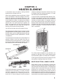
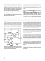
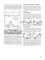
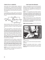
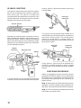
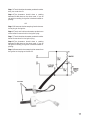
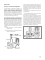
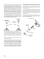
DRYER
STUDY COURSE
for Home Appliances
UNDERSTANDING DRYER:
• HEATER ELEMENT/GAS BURNER
COMPONENTS and
CHECKING PROCEDURES
Module 2
LIT 787849 Rev. C
For More Appliance Troubleshooting, Repair Help, & DIY Videos
Visit
A pplianceAssistant.com
Note: This Page was not included by Whirlpool Corporation
ApplianceAssistant.com is not affiliated Whirlpool Corporation
Whirlpool Corporation in no way endorses ApplianceAssistant.com
WHIRLPOOL CORPORATION does not assume any responsibility
or any liability in connection with the use of this manual.
© 1989, 1993, 1996, 2001 WHIRLPOOL CORPORATION
All rights reserved. No portion of this book may be reproduced in any form
without written permission from WHIRLPOOL CORPORATION.
® The trademarks WHIRLPOOL ,
,
trademarks of Whirlpool Corporation.
, and FSP are registered
INTRODUCTION
The material presented in this module is intended to provide you with an understanding of the
fundamentals of gas and electric dryer servicing.
Major appliances have become more sophisticated, taking them out of the screwdriver and pliers
category. Their electrical circuits include several different types of automatic controls, switches,
heaters, valves, etc.. Semiconductors, solid-state controls, and other components usually associated
with radio and television electronic circuits are being engineered into automatic washers, dryers,
dishwashers and refrigerators.
The appliance technician is emerging into a professional status of his own. He must prepare
himself now to be able to perform his duties today as well as to retain his professionalism in the
future.
No longer is on-the-job training sufficient to prepare technicians for the complicated procedures
required for todays sophisticated appliances. This training can best be obtained through organized
classroom study and application. However, much of the knowledge necessary to service todays
appliances can be obtained through study courses. Completion of this and other courses will provide
you with sufficient understanding of appliances and their operation to enable you to do minor
service. It will also serve as a valuable stepping stone to more advanced study and on-the-job training
to improve your servicing skills.
Information contained in this module is used on WHIRLPOOL® appliances.
1
TABLE of CONTENTS
PAGE
CHAPTER 1 - ELECTRICAL COMPONENTS................................................................... 3
Thermostats ....................................................................................................................... 4
Adjustable ....................................................................................................................... 4
Fixed ................................................................................................................................. 5
Operating Thermostats ................................................................................................... 6
High-Limit (Safety) Thermostats .................................................................................. 7
Thermal Fuse..................................................................................................................... 8
Buzzer ................................................................................................................................. 9
Push-To-Start Switch (Relay) ....................................................................................... 10
Door Switch ...................................................................................................................... 12
Two-Terminal ................................................................................................................ 12
Three-Terminal ............................................................................................................. 12
Five-Terminal ................................................................................................................ 13
Temperature Switch ....................................................................................................... 14
Drive Motors ..................................................................................................................... 16
Centrifugal Switch .......................................................................................................... 19
Timers ............................................................................................................................... 20
One and Two Cycle ..................................................................................................... 20
Three and Four Cycle .................................................................................................. 21
Timer Motor ..................................................................................................................... 23
Pulser Timer .................................................................................................................... 24
Bias Heater ...................................................................................................................... 26
Thermal Cut-Off .............................................................................................................. 27
TEST .............................................................................................. See Test Book LIT787852
*NOTE:
2
We recommend taking the TEST for MODULE 2, right after studying it.
CHAPTER 1
HEATER ELEMENT
In the electric dryer an electric heating element
substitutes for the heat of the sun.
When heat is applied to the surrounding air, it dries
the air and makes it react like a sponge. The hot air
heats the clothing, and causes moisture in the
clothing to vaporize and at the same time the dryness
of the heated air allows it to absorb the moisture
released by the clothing and discharge it out of the
exhaust vent. The more heat that is applied, the
faster the evaporation and the faster the drying
action. However, too much heat can damage the
clothing, so the heat must be controlled.
resistance readings of less than 50 ohms. Any time
an element does not indicate resistance, it is open
and should be considered defective.
In the mid 1970s, the expanded metal element (FlexA-Therm) was used for a short time. This element
consists of expanded metal wound around ceramic
insulators as shown below. The element mounts to
the current heater box with three mounting screws.
Because of less radiant heat given off by the element,
the heater box high-limit thermostat was changed to
a 225°F thermostat. Previous production used a
290°F thermostat.
Let’s look at the heat source of the electric dryer.
The wattage output determines the amount of heat
being generated. One watt equals 3.41 Btu (British
thermal units), and so a 4400-watt element will put
out about 15,004 Btu of heat. (4400 watts x 3.41 Btu
= 15,004 Btu.)
The heat element and heater box is shown below. The
element slides up into the heater box with an
interference fit for quiet operation. It is held in place
by one screw. When replacing the element, be sure
the heat shield and inlet manifold are in place.
INLET MANIFOLD
HEATER BOX
The Flex-A-Therm element is very efficient. For
example: A 5200-watt Flex-A-Therm element gives
the same heating effect as a 5600-watt coil element.
Checking across the terminals of this element should
also produce a reading of less than 50 ohms.
HIGH-LIMIT
THERMOSTAT
HEAT SELECTION—SINGLE LEVEL
TERMINAL
BLOCK
HEAT
SHIELD
HEATING
COILS
Dryer heating elements are made of coiled nichrome
resistance wire mounted in a frame. Ceramic
insulators separate the frame from the currentcarrying resistance wire. Checking across the
terminals of these elements should produce
Most electric dryers are designed to permit the
selection of heat levels according to the type of fabric
and the size of the load being dried. The single-level
element used in conjunction with two or three fixed
temperature thermostats of different cut-out
temperatures, will allow the user to have a choice of
several temperature selections. With this system, all
of the electrical circuitry to the fixed temperature
thermostats is controlled through the timer contacts.
3
Another temperature control system use with the
single-level heat element uses an adjustable
thermostat and a temperature selector switch. The
temperature selector switch controls the electrical
path to the operating thermostats. The timer controls
the electrical path to the temperature selector switch,
the motor, and other electrical components.
The single-level heat elements are rated at 4400
watts, 5200 watts or 5600 watts, determined by the
dryer model specifications and features. Always use
the correct element part number as called out in the
parts list for each dryer model.
The temperature control of dryers having a singlelevel heat element controlled by the action of the
timer and the operating thermostats, will be reviewed
first because the electrical circuitry is simple and easy
to describe.
First, you should know that centrifugal switch
contacts 1M to 2M are in the heater circuit as shown
below. Therefore, the motor must be running before
the heater can be energized, because the centrifugal
switch contacts are in the motor centrifugal switch.
If you refer to the timer schedule below, which
accompanies this wiring diagram, you will see that
several drying options are available. The user has
the choice of timed, permanent press, regular, or air
cycles.
1. TIMED CYCLE is a 75-minute cycle which has all
three of the timer switches closed for the first 70
minutes, at which time the contacts Y to R which
control the heater circuit open, while contacts Y to
BG and BG to TM remain closed for an additional 5
minutes, allowing the motor and timer to run for a
cool-down peroid. During the time when the heater
is on, the electrical circuit passes through the
operating thermostat and the high-limit thermostat.
The operating thermostat will control the on and off
cycles of the heating element and the temperature of
the air circulating through the dryer, as it senses the
air temperature near the dryer exhaust outlet.
Please note that the user of the dryer does not have
to use the full 75-minute cycle. The dial may be set
to a shorter increment of time, for example 30
minutes. The last 5 minutes of this timed schedule is
always an air-only cycle.
2. PERMANENT PRESS CYCLE is a 30-minute cycle
during which the heater contacts Y to R are closed
for the first 20 minutes. Contact Y to BG is closed for
the entire 30 minutes and contact BG to TM is closed
for slightly longer than 10 minutes at the end of the
cycle, so that there will be a circuit to the timer when
the Y to R contact opens.
3. REGULAR CYCLE is a cycle very similar to the
permmanent press cycle, except that it provides only
a 5-minute cool-down peroid after contact Y to R
opens.
Notice also, that the operating thermostat and the
high-limit thermostat are in the electrical circuit
which controls the heating element.
4
4. AIR CYCLE is a 19-minute cycle in which only Y
to BG and BG to TM contacts are closed. The air cycle
provides an air only option so that the user can fluff
pillows, etc.
The diagram below is showing the use of a simple
timer with two contacts. The heat selection is made
with a temperature-selector switch. The user
manually sets the switch for the control of the heater
element through the “high” temperature thermostat,
the “low” temperature thermostat, or for “air only.”
TWO-LEVEL HEATING ELEMENTS
There are two basic designs of two-level heat
elements. Earlier models had two elements wired in
parallel; later models have two elements wired in
series. A selector switch controls one of the elements
and allows the user to select between two drying
temperatures.
Parallel Method
When the selector switch is open, only one heating
element is energized. This occurs when gentle speed
is selected. This produces 4600 watts of heat. With
the switch closed on “super” speed, both heating
elements are energized and produce 5600 watts of
heat as shown below.
Series Method
The series method produces 4600 watts of heat when
the two elements are energized in series, and 5600
watts of heat when the selector switch is closed,
allowing one element to be energized while the other
element is bypassed as shown below.
The timer motor and the drive motor are controlled
through timer contacts Y to BG. Timer contacts Y to
R route the electrical current to the selector switch.
Depending on the setting you selected (in this case
the LOW temperature was selected). Contacts AH to
AH2 close the switch, then current can travel to the
operating thermostat LT1 to LT3. The “air” position
directs the current to a “dead” terminal which is not
connected to any electrical component and the drive
motor and timer operate through terminals Y to BG.
Selecting a high-temperature heat selection closes
the switch contacts, bridging the second element so
that only one element is energized. The current
passes through the lower resistance of only one
element and produces 5600 watts for high heat. In
effect, the selector switch establishes a line of least
resistance, bypassing the second element.
5
THREE-COIL ELEMENTS
Some dryers have a heating element composed of
three heater coils. This permits the dryer to operate
on a modulating type of heat, where one heat element
does not cycle off during any heat cycle, the other
two heat elements are thermostatically controlled and
do cycle off.
A three-position “air-heat” switch on the console
permits three settings NORMAL, DELICATE, and
AIR. The illustration shows the switch and element
circuits.
CHECKING PROCEDURE
Obtain an ohmmeter from your local store. We will
be doing RESISTANCE checks. This is the safest way
because the dryer is unplugged from the power source
and avoids the possibility of you receiving an
electrical shock.
NOTE: If the heat element has shorted out (blown
fuses), it is important that the timer and all
thermostats be checked for proper operation. Also
check the drive motor start switch, 1M and 2M should
be open. These components may have been damaged
when the heat element shorted.
Step 1 Remove one wire at a time, carefully labeling each wire according to the terminal marking on
the heat element. This procedure should assure that
the right wire is reconnected to the right terminal
after checking or replacement.
When the selector switch is set on AIR, the AH7 to
AH8 switch is open. No heat is produced. The drum
rotates and the blower circulates room temperature
air.
Choosing the NORMAL air-heat position closes airheat switches AH7 to AH8, and AH3 to AH9. This
provides a circuit through the 1500-watt, 1000-watt,
and 3100-watt sections of the heating element. Heat
input to the dryer will be 5600 watts. When the
exhaust stat is satisfied, switch contacts EX to EX
open, removing the 1000-watt and 3100-watt
elements from the circuit. The circuit to the 1500watt element section is always completed during the
entire “heat-on” phase of the drying cycle. It is not
thermostatically controlled.
Choosing the DELICATE position closes switch
contacts AH7 to AH8 and opens switch contact AH3
to AH9. This action removes the 1000-watt element
section from the circuit, and the dryer then functions
on the 1500-watt and 3100-watt sections for a total
heat input of 4600 watts. When the exhaust stat is
satisfied, it will cycle the 3100-watt section of the
element. The 1500-watt element does not cycle off.
NOTE: You will not see many two- or three-coil
heater elements, since they were phased out of
production in the early 1970’s.
6
Step 2 Set the ohmmeter scale to the lowest ohms
setting and ZERO the meter.
HEATER
BOX
HIGH LIMIT
THERMOSTAT
HEAT
ELEMENT
Step 3 Touch and hold one ohmmeter probe to one
of the terminals.
Step 4 Touch the other ohmmeter probe to the other
terminals.
Step 5 The ohmmeter should show a reading
between 5-50 ohms on the ohms scale. If you do not
get this reading, the heat element is bad and needs
replacing.
Step 13 Touch the other ohmmeter probe to any
bare metal (heater box) on the dryer.
HEATER
BOX
HIGH LIMIT
THERMOSTAT
Step 14 The ohmmeter should show an open circuit.
If not, the heat element is bad and needs replacing.
Step 15 Check the other terminals as in steps 12,
13 & 14.
Step 16 Reconnect the heat element wires to the
proper terminals as previously marked.
HEAT
ELEMENT
Step 6 Touch and hold one ohmmeter probe to the
middle terminal (H2).
Step 7 Touch the other ohmmeter probe to the outside terminal having two wires (H1).
Step 8 The ohmmeter should show a reading
between 1-4 ohms on the ohms scale. If you do not
get this reading, the heat element is bad and needs
replacing.
Step 9 Touch and hold one ohmmeter probe to one
of the outside terminals (H1).
Step 10 Touch the other ohmmeter probe to the
other outside terminal (H3).
Step 11 The ohmmeter should show a reading
between 6-10 ohms on the ohms scale. If you do not
get this reading, the heat element is bad and need
replacing.
NOTE: This heat element should not be shorted to
ground. Make sure the heat element is retained by
the insulators and does not contact anything else.
HEATER
BOX
HEAT ELEMENT
HEAT
ELEMENT
Step 12 Touch and hold one of the ohmmeter probes
to any one of the three terminals.
7
CHAPTER 2
GAS BURNER
SEQUENCE OF BURNER OPERATION
The instant voltage is applied to the gas burner, a
momentary circuit is established from 1V through
the No. 1 coil, the latching switch, the radiant sensor
switch and back to 3V as shown below.
Magnetism developed by the No. 1 coil will raise the
valve plunger and cause the latching switch to
transfer to the other side. No gas will flow at this
instant.
Another circuit is established through the ignitor, the
sensor switch and back to terminal 3V.
The No. 2 coil is not energized because circuitry is
shunted through the sensor switch, which is the path
of least resistance.
The latching switch is now shown transferred. The
switch is a make-before-break design. Circuitry is
now through the No. 1 coil, the latching switch, and
back to 3V. The latching switch will maintain this
latched position as long as the gas burner remains
energized as shown below.
Voltage continues to be applied to the ignitor until it
heats to 2200°F. The radiant sensor switch contacts
will sense this radiant heat, causing the sensor
contacts to open as shown below.
With the sensor switch now open, the only path for
the current to take is through the No. 2 coil.
Energizing the No. 2 coil opens the No. 2 valve,
allowing gas to flow through the burner, which is
ignited by the intense 2200°F heat of the ignitor. The
gas flame will continue to hold the radiant sensor
open.
When the gas burner circuitry is briefly interrupted
by unplugging the machine, turning the timer OFF,
or opening the loading door, the No. 1 and No. 2 valves
will both drop out, shutting off the flow of gas through
the valve assembly. If circuitry is quickly restored,
only the No. 2 valve will be energized and the radiant
sensor contact will remain open. Because the ignitor
is now in series with the No. 2 coil, it will not operate
as shown below.
Circuitry does not exist at this time to energize the
No. 1 coil, until the radiant sensor switch contact cools
sufficiently for it to close. This action will permit the
burner to recycle and again ignite main burner gas.
8
THE SPLIT-COIL SILICON
CARBIDE BURNER
Magnetism created by the hold coil is sufficient to
hold the No. 1 valve open.
Many silicon carbide gas burners utilize a split coil
design. Valve No. 1 has two coils to actuate its
plunger, thus giving the split-coil burner its name.
Neither the hold coil nor the assist coil alone is strong
enough to open the valve. The combined magnetic
action of both coils is needed. Once the valve is open,
however, the hold coil can hold it open by itself. The
circuits of both coils will serve as a quick shut-off
function.
When voltage is applied to 1V and 3V, a circuit is
completed from 1V to the ignitor, and through the
sensor to 3V as shown below.
If voltage to the burner is momentarily interrupted
and then restored, circuitry as illustrated below will
exist.
Simultaneously, the hold coil is energized, and the
assist coil is energized through the radiant sensor.
This action means that the ignitor is heating and No.
1 valve is open. No gas flows, however, until No. 2
valve also opens. Note the resistor in series with the
assist coil. This is a balancing resistor which is used
only on one style of valve. It will not be present on all
split-coil valves.
The ignitor has reached a temperature sufficient to
open the radiant sensor contacts as shown below. This
action causes valve No. 2 to be energized through
the ignitor. Gas flows through the valve and is ignited
instantly by the still hot ignitor. Current through the
assist coil on valve No. 1 is very low at this point.
Valve No. 2 is open but magnetism produced by the
hold coil is not sufficient to open the No. 1 valve. When
the sensor cools and the sensor contacts reclose, reignition will occur.
9
Another “glow-sil” ignitor being used on gas dryers
is shown below.
GLOW-SIL IGNITORS
The “glow-sil” (also known as the “posi-lite”) ignition
burner uses a glowing silicon ignitor to ignite the
main burner gas. The ignitor is formed from
recrystallized silicon carbide and is very brittle. Care
must be used when servicing this burner to prevent
damage to the ignitor as shown below.
ELECTRICAL
CONNECTOR
GLOW-SIL IGNITOR
CERAMIC
BASE
LOCATING FIN
Although you must be careful, the glow-sil ihnitor is
easily removed and replaced. Looking below, you can
see that the ignitor is held in place by the clamping
action of the mounting clips. You must be very careful
whenever you are installing these clips. Otherwise,
you will damage the ignitor.
CERAMIC
INSULATOR
This ignitor has the terminal ends molded into a
ceramic base and a terminal block for connection to
the burner wiring harness. The revised ignitor
mounts to the gas burner as shown below. Its
performance characteristics are no different than the
other glow-sil ignitor.
MOUNTING
SCREW
ELECTRICAL
CONNECTOR
MICA INSULATOR
VENTURI
MOUNTING
SCREW
GLOW-SIL
IGNITOR
MOUNTING
CLIPS
In this illustration, you can also identify the ceramic
insulator, the mica insulator and the mounting screw.
These “glow-sil” ignitors must be handled very
carefully. If you drop the ignitor or give it a severe
jolt, the fragile silicon carbide crystals will probably
fracture.
CHECKING PROCEDURE
Obtain an ohmmeter from your local store. We will
be doing RESISTANCE checks. This is the safest way
because the dryer is unplugged from the power source
and avoids the possibility of you receiving an
electrical shock.
Step 1 Refer to the instructions that came with your
ohmmeter to find the proper scale to measure 50400 ohms. Set the ohms scale and ZERO the meter.
Step 2 Touch and hold one ohmmeter probe to one
of the sides, just under the fin.
10
Step 3 Touch the other ohmmeter probe to the other
side, just under the fin.
Step 4 The ohmmeter should show a reading
between 50-400 ohms on the ohms scale. If you do
not get this reading, the ignitor is bad and needs replacing.
OR
Step 5 Disconnect the harness plug from the burner
to the plug on the ignitor.
Step 6 Touch and hold one ohmmeter probe to one
of the bullet-like terminals in the ignitor plug.
Step 7 Touch the other ohmmeter probe to the other
bullet-like terminal in the ignitor plug.
Step 8 The ohmmeter should show a reading
between 50-400 ohms on the ohms scale. If you do
not get this reading, the ignitor is bad and needs replacing.
Step 9 Reconnect the harness plug that comes from
the ignitor to the plug on the burner.
IGNITORS
11
RADIANT SENSOR
Step 3 Touch and hold one ohmmeter probe to one
of the terminals on the sensor.
The radiant heat sensor is mounted on the side of
the burner funnel assembly. A cut-out in the funnel
allows radiant heat from the ignitor and the gas flame
to reach the sensor as shown below.
Step 4 Touch the other ohmmeter probe to the other
terminal on the sensor.
Step 5 The ohmmeter should show ZERO resistance (continuity). If not, the sensor is bad and needs
replacing.
Step 6 If this check showed ZERO resistance, then
reconnect the wires to the proper terminals on the
sensor.
Step 7 Remove the toe panel.
Step 8 Set the timer control and start the dryer.
Step 9 Watch the ignitor for a couple of minutes. If
this stays red hot and the gas does not come out and
ignite, the sensor is bad and needs replacing.
RADIANT
SENSOR
BURNER
FUNNEL
MOUNTING
BRACKET
The ignitor will normally reach a temperature of
2200°F in about 15 to 30 seconds after line voltage is
applied. The radiant sensor opens the circuit to the
ignitor when this temperature is reached. The gas
valve is energized simultaneously, and when gas
contacts the hot ignitor, ignition takes place.
CHECKING PROCEDURE
Obtain an ohmmeter from your local store. We will
be doing RESISTANCE checks. This is the safest way
because the dryer is unplugged from the power source
and avoids the possibility of you receiving an
electrical shock.
Step 1 Remove one wire at a time, carefully labeling each wire according to the terminal marking on
the sensor. This procedure should assure that the
right wire is reconnected to the right terminal after
checking or replacement.
Step 2 Set the ohmmeter scale to the lowest ohms
setting and ZERO the meter.
12
RADIANT SENSOR
GAS FLOW
The Dryer Gas Pressure Regulator
The sole function of a gas pressure regulator is to
maintain, within close limits, a constant outlet
(burner, or “manifold”) pressure, regardless of inlet
pressure changes. The regulator must consequently
sense all changes in inlet pressure and be able
automatically to adjust the gas flow as required. The
sensing device is a diaphragm and spring
arrangement attached to a valve ball which is used
to restrict gas flow through the ball seat.
All Whirlpool-built gas dryers are shipped with gas
burner assemblies that have a gas pressure regulator
built into the main valve body. The sole function of
the regulator is to reduce and maintain within close
limits a constant gas pressure in the burner assembly
of three (3) inches of water column. In order for the
regulator to function properly, gas supply pressure
to the dryer must be above 3 inches of water column.
The regulator cannot increase gas pressure. The parts
involved in controlling the gas pressure are, starting
at the top:
These two (2) parts have holes through them to vent
the area above the diaphragm to the atmosphere.
This is done so that when the gas pressure below the
diaphragm increases or decreases, it allows the
diaphragm to move up or down, closing or opening
the valve below.
• The Spring is next—it applies pressure to the top
of the diaphragm.
• The Diaphragm Assembly—is made of a flexible
material and has a valve attached to it.
As gas enters through the valve opening, it applies
pressure to the underside of the diaphragm, which
in turn pulls the valve up, reducing the size of the
valve opening. The higher the inlet pressure, the more
the valve opening size is reduced. This will effectively
control the pressure of gas that enters the burner. In
those rare occasions where regulator adjustment is
necessary, remove the leak limiter cap screw and turn
the adjustment screw to change the gas pressure
regulated by the regulator as shown below.
• The Leak Limiter Screw — in case the diaphragm
develops a leak.
• The Adjustment Screw — for adjusting the spring
pressure as shown below.
VENT CAP
LEAK LIMITER
ADJUSTMENT SCREW
SPRING
DIAPHRAGM
VALVE
13
Gas Flow Through the Valves
After passing through the regulator, the next thing
the gas encounters is the two (2) electrical solenoid
control valves. The most important things to
remember about the valves are:
1. Each burner assembly always has two (2) valves.
2. Both of the valves are spring loaded closed and
the solenoids must be energized to open them.
could leave a burr which would change the flow
pattern of the gas and create turbulence inside the
burner tube. This problem usually causes slower
movement through the tube, reducing the amount of
primary air being sucked in.
As the gas leaves the orifice, it draws primary air
through the primary air opening. Recent production
burners do not require any air adjustment when used
with natural or LP gas, and therefore do not need
the air shutter assembly pictured below.
3. Both valves must be open for the burner to work
as shown below.
SOLENOIDS
CLAMP
SCREW
SPRING
SHUTTER
These gas flow diagrams can help you visualize what
is happening when the various circuits are energized.
After passing through the valves, the gas comes to
the orifice. The main function of the orifice is to
control the gas output from the valve body at a set
level into the burner and shutter assembly. Since
burners are designed to perform best at their rated
inputs, the orifice is very important as shown below.
In operation, the stream of gas issuing from the main
burner orifice is aimed into the throat of the burner.
The speed of the gas stream sets up a vacuum
(suction), drawing air into this lower-pressure area
through the primary air port. As the air and gas
mixture passes through the venturi, or mixing barrel,
the mixing of the air and gas is completed. This air
and gas mixture then flows out by the flame scoop. It
is at this point where secondary air is mixed in and
combustion takes place. The flame scoop is designed
to spread the flame and control the amount of
secondary air being mixed with the gas as shown
below.
PRIMARY AIR
GAS JET
FLAME SCOOP
ORIFICE
GAS
VENTURI THROAT
PRIMARY AIR
The orifice is a precision-made part and should never
be redrilled in the field to alter gas flow. Hand drilling
14
SECONDARY AIR
A bent burner-mounting bracket can cause the burner
to be out of line in its relationship with the valve
body and orifice. Should the venturi be misaligned,
as shown below, the flow of gas will strike the barrel
of the venturi throat, reducing its speed and
consequently reducing the amount of primary air
sucked through the port.
Therefore, precise alignment of the orifice to the
venturi is of the utmost importance.
REDUCED
PRIMARY AIR
Make sure to refer to the parts list for this air shutter
assembly when ordering the manufactured gas
conversion kit or other parts of the revised burner
assembly.
Without the conversion kit, the burner will be
extremely noisy when operating on manufactured
(type 3) gas.
All gas dryers are shipped from the factory orificed,
and with the regulator adjusted to burn natural gas.
Orifice or regulator pressure changes may be
necessary for operation on mixed or manufactured
gases. Consult the local utility about this.
Converting to LP Gas
MISALIGNED
VENTURI
The tell tale sign of too little primary air is a yellow
flame. This type of flame is much lower in
temperature than a normal flame and one that
usually gives off carbon or soot. The yellowness is
due to the incomplete burning of carbon contained in
the gas. It should be noted that dust in the
atmosphere will cause the burner flame to take on a
reddish cast or to show momentary red flecks as dust
or lint is drawn through the air shutter. This
condition can be disregarded since it is a normal
occurrence.
You probably won’t experience a condition of too much
primary air, since it is not likely to occur except on
manufactured gas.
Too much primary air will result in what is called a
“hard” or blowing flame. One sign of this type of flame
is an increase in the noise level of the burner. Another
clue to excessive primary air is flashback, where
ignition starts to migrate back into the burner tube.
A third clue is a fairly loud popping noise when the
main burner shuts off. In all cases you need only to
reduce the primary air to correct the problem. Since
recent production burners are produced without air
shutters, you will need to install an air shutter
conversion kit. The conversion kit includes an air
shutter as pictured below.
AIR
SHUTTER
Liquefied petroleum gas or L.P. is mainly propane
(2500 B.T.U. per cubic foot) or butane (3200 B.T.U.),
or a mixture of both. It is widely distributed in rural
areas which may be far beyond city gas lines. L.P.
gas under moderate pressure is converted to a liquid
and consequently is easily handled and transported
in pressurized bottles or tanks. When released to
normal atmospheric pressure and temperature, the
pressurized liquid automatically returns to its
gaseous form. L.P. gas is heavier than air and will
lay in the lowest spot it can find if released into a
room. As a result, technicians working the L.P. gas
should have special training to recognize the safety
procedures which need to be taken. Conversions to
L.P. gas and storage tank regulator adjustments
should be performed by trained (usually licensed)
LPG technicians.
The LPG fuels are always regulated at the bottle as
shown below, or at a larger supply tank, eliminating
the need for regulation at the burner unit.
PRESSURE
REGULATOR
TANK
As a result, the gas pressure regulator on the burner
control is immobilized (held open) by installing a
special regulator plug. The conversion kit number
for converting the burner can be found on the burner
base or in the parts list.
15
Remove the leak limiting cap screw and gasket from
the pressure regulator and install the regulator plug
and gasket furnished with the kit. The plug, shown
below, is designed without a vent hole and has a long
stem that protrudes down through the hole in the
adjustment screw and pushes against the diaphragm,
holding the valve in the open position. The plug cap
will always be color coded with a blue top for
identification. The reason the vent hole is not present
on the LP regulator plug is because the regulator is
held in its full open position, and there is no need for
the regulator diaphragm to move up and down as
was described previously. Also by eliminating the
hole, a potential gas leak is eliminated in the event
that the regulator diaphragm ruptures.
ADD TO
REGULATOR
Converting From LPG to Other Gases
If a conversion is to be made from LPG back to
natural, mixed or manufactured gases, observe the
following procedures.
If the pressure regulator was demobilized, reactivate
the pressure regulator by removing the LP regulator
plug and by adding the parts shown below. Also,
install the specified burner orifice and pilot orifice if
a pilot is used.
Providing local codes permit, reconversion from LPG
to natural, mixed, or manufactured gas may be done
by non-licensed personnel.
ADD TO REGULATOR
REMOVE FROM
REGULATOR
CAP
GASKET
REGULATOR
PLUG
GASKET
ADJUSTING
SCREW
SPRING
The other parts included in the conversion kit are
easily installed by following the directions included
in the kit. Remove the complete burner assembly from
the machine. Remove the orifice with a 3/8" box
wrench, and reinstall the new orifice received in the
kit.
On burners that have a pilot light, the pilot orifice
must also be changed.
Reinstall the burner and apply the two (2) conversion
decals furnished with the kit. One must be placed
over the burner data label on the burner baseplate
and the other is applied next to the data rating plate
in the door well. These decals must be applied to meet
A.G.A. requirements and to warn any future
technicians who might be servicing the product.
Generally, hookup must be made by a L.P. gas dealer.
16
GASKET
LEAK LIMITING
DEVICE
The Orifice
The orifice performs two functions:
1. It controls the amount of gas to be burned.
2. It directs the flow of gas being injected into
the burner.
The amount of gas being supplied to the burner is
controlled by the size of the opening in the orifice.
The size of the orifice opening is determined by the
Btu rating of the dryer and by the type of gas available
for fuel.
1. All gas dryers are manufactured with natural gas
orifices.
2. All gas burners can be converted for use with different gases through orifice change.
NOTE: Do not ream or enlarge any burner orifice.
These orifices are precision made in respect to length,
hole size, and modulator-needle position. Use only
the replacement orifice specified for conversion to
another type of gas. Each orifice has its identification
number stamped on it. You may have to remove the
orifice to read the number. The location of the orifice
is shown below.
5. Reconverting back to natural gas burners in the
field does not invalidate AGA approval, if done
according to instructions.
6. A decal, supplied with each conversion kit, must
be affixed next to the rating plate on the dryer
door well. When the pressure regulator is immobilized for an LPG conversion, place the additional decal on the burner baseplate.
BTU Ratings
As we continue with our study of gas drying heat,
you will see the term BTU used many times.
The term BTU stands for British Thermal Unit and
represents a measurement of heat volume. One Btu
is that amount of heat required to raise the
temperature of one pound of water one degree
Fahrenheit. For example, the heat generated by a
burning wood match is approximately one BTU. The
BTU value of gas fuels is customarily given as BTU
per cubic foot of gas. Thus the BTU rating is the
amount of heat (not the temperature) a burner
creates while operating for one hour. Most gas dryers
are designed for 20,000 to 37,000 Btu per hour input.
The design and the size of a number of operating
components in the dryer are determined according
to the BTU rating of the dryer.
This is a necessary measure to ensure that the volume
of air movement in the dryer is coordinated with the
BTU input. Otherwise, overheating or underheating
would certainly result.
Overrating a burner beyond rating plate input, or
severe underrating, can result in shortened
component life, faulty ignition, poor combustion and
lack of air adjustment range.
ORIFICE
3. Special kits or orifices for converting burners from
one gas to another are available. To determine the
correct kit for a specific dryer, refer to the current
repair parts list at your parts source.
NOTE: For areas over 2000 feet elevation above sea
level, de-rate from nameplate rating 4% per 1000 feet
elevation. To make the job easier, most gas companies
have charts that will give you the orifice size required
at different elevations.
4. Correct orifices should be determined and installed
before delivering new dryers.
17
Gas Fuels
There are four different types of gas fuels available
for use in domestic gas dryers. These four are
sometimes designated by number.
No. 1—Natural gas.
No. 2—Mixed gas.
No. 3—Manufactured gas.
No. 4—Liquefied petroleum gas.
No. 1—Natural gas is found underground, sometimes
with oil (petroleum). In its natural state it is called
“wet” gas, since it contains heavy hydrocarbons such
as propane, butane and other substances.
Gas suppliers will process this wet gas, removing the
heavier hydrocarbons and leaving only methane and
ethane. In some areas, natural gas will contain
significant amounts of hydrogen sulfide and is called
“sour” gas. Sour gas has a corrosive action on brass
parts and consequently aluminum orifices must be
used in these supply areas. Natural gas may contain
between 900 and 1200 BTU per cubic foot, but it will
usually contain between 1000 and 1100 BTU. This
would seem to indicate that there is a great variation
in the BTU content of the gas at any one location,
but that is not true. Utilities are required by law to
hold the BTU content of the gas to very close
tolerances. You will notice also in the chart below,
that the specific gravity of natural gas is .65 to .70.
Gas Fuels
BTU Value/Cu. Ft.
Specific Gravity
Natural
1075 (may vary from
900 to 1200)
.65 to .70
Mixed
1075 (may vary from
900 to 1200)
.50
Manufactured
No. 2—When manufactured gas is combined with
natural gas, it is called mixed gas. It has a Btu rating
of between 700 and 900 per cubic foot. The specific
gravity is usually about .50. Mixed gas was
distributed extensively in the Eastern part of the U.S.
at one time, but it has been replaced by natural gas
in most places.
No. 3—Manufactured (artificial) gas is made from
coal and petroleum with a heat value of 500 to 700
Btu per cubic foot. Its specific gravity will be about
.38 to .40. Remember that a conversion kit which
includes orifices and air shutter for the burner must
be installed when using this type of gas.
No. 4—Liquified Petroleum Gas (LPG) is mainly
propane (2500 Btu per cubic foot), butane (3200 Btu),
or a mixture of both. In northern climates where the
temperatures regularly drop below 32 degrees
Fahrenheit, you can expect that propane gas will be
used exclusively. Butane gas will not vaporize at
temperatures below 32 degrees, and therefore it can
only be used in southern climates. The illustration
below shows the great difference in the boiling points
of the gases which we use in the gas dryers.
BOILING POINTS of GASES
200°
100°
32°
LP
ZERO
-44°
.38 to .40
BUTANE
PROPANE
-100°
-200°
NATURAL
MIXED
MANUFACTURED
-300°
Propane
1.53
Butane
2.0
DEGREES
The specific gravity of any gas is the comparison of
its weight to the weight of air which is a specific
gravity of 1. So you can see now that natural gas is
lighter than air.
18
FAHRENHEIT
As mentioned previously, all LPG containers have
their own regulators which should be set to
approximately 11 inches water column (WC)
pressure.
At the present time it is only necessary for you to
know that the regulator for LP gas installations is
located at the tank, as shown below.
PRESSURE
REGULATOR
TANK
Adjustments to the LP gas regulator should be made
by a qualified LP gas service technician.
LP gas is heavier than air. When a leak is present in
a system using LP gas, this gas will lay low and form
pools or puddles and will not readily disperse,
resulting in a dangerous situation. The proper way
to check for leaks with LP gas, or any other gas is to
use a bubble solution. The bubble solution can be a
mixture of liquid detergent mixed with a little water,
or you can use the bubble solution which is sold for
children’s bubble-blowing pleasure. Use a small brush
to put the bubble solution around each joint on the
tubing or pipe in areas where it is normally under
pressure. Bubbles will appear when there is a leak.
NOTE: Never ever use a flame to test for a gas leak,
regardless of the type of gas.
19
NOTES
20
BLANK
BLANK