1
PG-C20XU
PG-C20XE
AN-Z7T
SERVICE MANUAL
SERVICE-ANLEITUNG
S31Q7PG-C20XU
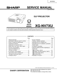
LCD PROJECTOR
LCD PROJEKTOR
PG-C20XU
PG-C20XE
MODELS
MODELLE
ATTACHMENT ADAPTOR
ANSCHLUSSADAPTER
AN-Z7T
In the interests of user-safety (Required by safety regulations in some countries) the set should be restored
to its original condition and only parts identical to those specified should be used.
Im lnteresse der Benutzersicherheit (erforderliche Sicherheitsregeln in einigen Ländern) muß das Gerät in seinen
Originalzustand gebracht werden. Außerdem dürfen für die spezifizierten Bauteile nur identische Teile verwendet
werden.
SHARP CORPORATION
This document has been published to be used for
after sales service only.
1The contents are subject to change without notice.
PG-C20XU
PG-C20XE
AN-Z7T
CONTENTS
Page
Page
• SPECIFICATIONS ............................................. 3
• IMPORTANT SERVICE SAFETY
NOTES (for USA) ............................................... 4
• NOTE TO SERVICE PERSONNEL ................... 5
• OPERATION MANUAL ...................................... 8
• REMOVING OF MAJOR PARTS ..................... 13
• RESETTING THE TOTAL LAMP TIMER ......... 19
• THE OPTICAL UNIT OUTLINE ........................ 20
• ELECTRICAL ADJUSTMENT .......................... 23
• TROUBLE SHOOTING TABLE ........................ 31
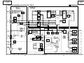
• CHASSIS LAYOUT .......................................... 80
• BLOCK DIAGRAM ........................................... 82
• OVERALL WIRING DIAGRAM ........................ 84
•
•
•
•
•
DESCRIPTION OF SCHEMATIC DIAGRAM ... 86
WAVEFORMS .................................................. 87
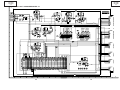
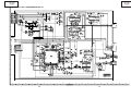
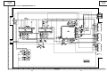
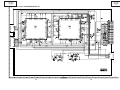
SCHEMATIC DIAGRAM .................................. 88
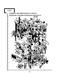
PRINTED WIRING BOARD ASSEMBLIES ... 128
PARTS LIST
Ë ELECTRICAL PARTS ............................... 134
Ë CABINET AND MECHANICAL PARTS .... 149
Ë ACCESSORIES PARTS ........................... 153
Ë PACKING PARTS ..................................... 153
• PACKING OF THE SET ................................. 154
• ATTACHMENT ADAPTOR ............................. 155
INHALT
Seite
• TECHNISCHE DATEN .....................................
• HINWEISE FÜR DAS
WARTUNGSPERSONAL .................................
• BEDIENUNGSANLEITUNG .............................
• ENTFERNEN DER HAUPTTEILE ...................
• RÜCKSTELLEN DES
LAMPENBETRIEBSZEIT-TIMERS ..................
• BESCHREIBUNG DER OPTIK-EINHEIT ........
• ELEKTRISCHE EINSTELLUNG ......................
• FEHLERSUCHTABELLE .................................
• CHASSIS-ANORDNUNG ................................
• BLOCKSCHALTBILD .......................................
• GESAMTSCHALTPLAN ...................................
• BESCHREIBUNG DES SCHEMATISCHEN
Seite
43
•
•
•
•
44
45
50
56
57
60
68
80
82
84
•
•
2
SCHALTPLANS ............................................... 86
WELLENFORMEN ........................................... 87
SCHEMATISCHER SCHALTPLAN .................. 88
LEITERPLATTENEINHEITEN ....................... 128
ERSATZTEILLISTE
Ë ELEKTRISCHE BAUTEILE ...................... 134
Ë CEHÄUSE UND MECHANISCHE
BAUTEILE ................................................ 149
Ë ZUBEHÖRTEILE ...................................... 153
Ë VERPACKUNGSTEILE ............................ 153
VERPACKEN DES GERÄTS ......................... 154
ANSCHLUSSADAPTER ................................ 155
PG-C20XU
PG-C20XE
AN-Z7T
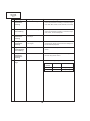
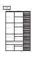
Specifications
Product type
Model
Video system
Display method
LCD panel
Lens
Projection lamp
Contrast ratio
Video input signal
S-video input signal
Horizontal resolution
Audio output
Computer RGB input signal
Pixel clock
Vertical frequency
Horizontal frequency
Computer control signal
Speaker system
Rated voltage
Input current
Rated frequency
Power consumption
Operating temperature
Storage temperature
Cabinet
I/R carrier frequency
Dimensions (approx.)
Weight (approx.)
Supplied accessories
Replacement parts
LCD Projector
PG-C20XU/XE
PAL / PAL 60 / PAL- M / PAL- N / SECAM / NTSC 3.58 / NTSC 4.43 / DTV 480P
LCD panel X 3,RGB optical shutter method
Panel size:0.9" (22.9mm) (13.9 [H ] X 18.5 [W ] mm))
Display method:Translucent TN liquid crystal panel
Drive method:TFT (Thin Film Transistor)Active Matrix panel
No.of dots:786,432 dots (1,024 [H ] X 768 [V ])
1 – 1.2X zoom lens, F2.3 – 2.6, f = 36.0 – 43.2 mm
DC 150 W lamp
500:1
RCA Connector:VIDEO,composite video,1.0 Vp-p,sync negative,75 Ω terminated
RCA Connector:AUDIO,0.5 Vrms more than 22 kΩ (stereo)
4-pin Mini DIN connector
Y (luminance signal):1.0 Vp-p,sync negative,75 Ω terminated
C (chrominance signal):Burst 0.286 Vp-p,75 Ω terminated
580 TV lines (video input)
1.0 W (monaural)
15-PIN MINI D-SUB CONNECTOR (COMPUTER INPUT 1 port,COMPUTER OUTPUT port):
RGB separate/composite sync/sync on green type analog input:0 – 0.7 Vp-p,positive,
75 Ω terminated
STEREO MINIJACK:AUDIO,0.5 Vrms,more than 22 kΩ (stereo)
HORIZONTAL SYNC.SIGNAL:TTL level (positive/negative)or composite sync (Apple only)
VERTICAL SYNC.SIGNAL:Same as above
12 – 108 MHz
43 – 85 Hz
15 – 80 kHz
9-pin Mini DIN female connector (RS-232C port)
1 7⁄64" (2.8 cm) round
AC 100 – 240 V
2.6 A
50/60 Hz
230 W (Selecting "OFF" in the "Power Save Mode".)
200 W (Selecting "ON" in the "Power Save Mode".)
41 °F to 95 °F (+ 5 °C to + 35 °C)
− 4 °F to 140 °F (− 20 °C to + 60 °C)
Plastic
38 kHz
10 15⁄64" (W) X 2 29⁄32" (H) X 8 5⁄32" (D)(260 X 74 X 207 mm)(main body only)
10 15⁄64" (W) X 3 15⁄64" (H) X 8 5⁄32" (D)(260 X 82 X 207 mm)(including
adjustment feet and projecting parts)
5.73 lbs.(2.6 kg)
Remote control, Two AAA size batteries, Power cord (11' 10" ,3.6 m), Computer RGB cable (9' 10"
,3 m), Computer audio cable (9' 10", 3 m), PS/2 mouse control cable (3' 3", 1 m), USB mouse
control cable (4' 11" ,1.5 m), DIN-D-sub RS-232C cable (6 45⁄64" ,15 cm), Remote mouse receiver,
Extra air filter, Lens cap (attached), Lens cap strap, CD-ROM,
Lamp unit (Lamp/cage module) (BQC-PGC20X//1), Remote control (RRMCG1613CESA), AAA
size batteries, Power cord (CACCU5013DE01 (PG-C20XU), QACCV4002CEZZ (PG-C20XE),
QACCB5024CENA (PG-C20XE)), Computer RGB cable (QCNWG0002CEZZ), Computer audio
cable (QCNW-4870CEZZ), PS/2 mouse control cable (QCNW-5113CEZZ), USB mouse control
cable (QCNW-5680CEZZ), DIN-D-sub RS-232C cable (QCNW-5288CEZZ), Remote mouse receiver (RUNTK0694CEZZ), Air filter (PFILD0123CEZZ), Lens cap (PCOVZ1095CEKA), Lens cap
strap (UBNDT0013CEZZ), CD-ROM (UDSKA0029CEN1 (PG-C20XU), UDSKA0048CEN1 (PGC20XE)), LCD projector operation manual (TINS-7204CEZZ (PG-C20XU), TINS-7271CEZZ (PGC20XE)), LCD projector quick reference guide (TINS-7205CEZZ (PG-C20XU), TINS-7272CEZZ
(PG-C20XE), TINS-7284CEZZ (PG-C20XE), TINS-7285CEZZ (PG-C20XE))
This SHARP projector uses LCD (Liquid Crystal
Display)panels.These very sophisticated panels contain 786,432
pixels (RGB)TFTs (Thin Film Transistors).As with any high technology electronic equipment such as large screen TVs,video systems
and video cameras,there are certain acceptable tolerances that the
equipment must conform to.
This unit has some inactive TFTs within acceptable tolerances which
may result in illuminated or inactive dots on the picture screen.This
will not affect the picture quality or the life expectancy of the unit.
If you have any questions about this matter,please call toll free 1888-GO-SHARP (1-888-467-4277). U.S.A.ONLY
Specifications are subject to change without notice.
3
PG-C20XU
PG-C20XE
AN-Z7T
IMPORTANT SERVICE SAFETY NOTES (for USA)
Ë Service work should be performed only by qualified service technicians who are
thoroughly familiar with all safety checks and servicing guidelines as follows:
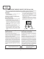
» Use an AC voltmeter with sensitivity of 5000 ohm per
volt., or higher, sensitivity to measure the AC voltage
drop across the resistor (See Diagram).
» All checks must be repeated with the AC plug
connection reversed. (If necessary, a non-polarized
adapter plug must be used only for the purpose of
completing these checks.)
Any reading of 0.3 volts RMS (this corresponds to
0.2 milliamp. AC.) or more is excessive and indicates
a potential shock hazard which must be corrected
before returning the unit to the owner.
WARNING
1. For continued safety, no modification of any circuit
should be attempted.
2. Disconnect AC power before servicing.
BEFORE RETURNING THE PROJECTOR:
(Fire & Shock Hazard)
Before returning the projector to the user, perform
the following safety checks:
1. Inspect lead wires are not pinched between the
chassis and other metal parts of the projector.
2. Inspect all protective devices such as non-metallic
control knobs, insulating materials, cabinet backs,
adjustment and compartment covers or shields,
isolation resistor-capacity networks, mechanical
insulators, etc.
3. To be sure that no shock hazard exists, check for
current leakage in the following manner:
» Plug the AC cord directly into a 120-volt AC outlet,
(Do not use an isolation transformer for this test).
» Using two clip leads, connect a 1.5k ohm, 10 watt
resistor paralleled by a 0.15µF capacitor in parallel
between all exposed metal cabinet parts and earth
ground.
AC
VOLTMETER
1.5k ohm (10W)
0.15µF
TEST PROBE
TO EXPOSED
METAL PARTS
CONNECT TO KNOWN
EARTH GROUND
12345678901234567890123456789012123456789012345678901234567890121234567890123456789012345678901212
12345678901234567890123456789012123456789012345678901234567890121234567890123456789012345678901212
12345678901234567890123456789012123456789012345678901234567890121234567890123456789012345678901212
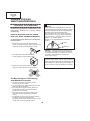
SAFETY NOTICE
AVIS POUR LA SECURITE
Many electrical and mechanical parts in LCD Projector
have special safety-related characteristics.
These characteristics are often not evident from visual
inspection, nor can protection afforded by them be
necessarily increased by using replacement components
rated for higher voltage, wattage, etc.
Replacement parts which have these special safety
characteristics are identified in this manual; electrical
components having such features are identified by “å”
and shaded areas in the Replacement Parts Lists and
Schematic Diagrams. For continued protection,
replacement parts must be identical to those used in the
original circuit. The use of a substitute replacement parts
which do not have the same safety characteristics as
the factory recommended replacement parts shown in
this service manual, may create shock, fire or other
hazards.
De nombreuses pièces, électriques et mécaniques, dans
les projecteur à LCD présentent des caractéristiques
spéciales relatives à la sécurité, qui ne sont souvent
pas évidentes à vue.
Le degré de protection ne peut pas être nécessairement
augmentée en utilisant des pièces de remplacement
étalonnées pour haute tension, puissance, etc.
Les pièces de remplacement qui présentent ces
caractéristiques sont identifiées dans ce manuel;
les pièces électriques qui présentent ces particularités
sont identifiées par la marque “å” et hachurées dans la
liste des pièces de remplacement et les diagrammes
schématiques. Pour assurer la protection, ces pièces
doivent être identiques à celles utilisées dans le circuit
d’origine. L’utilisation de pièces qui n’ont pas les mêmes
caractéristiques que les pièces recommandées par
l’usine, indiquées dans ce manuel, peut provoquer des
électrocutions, incendies ou autres accidents.
WARNING: The bimetallic component has the primary
conductive side exposed. Be very careful in
handling this component when the power is on.
AVERTISSEMENT: La composante bimétallique dispose du
conducteur primaire dénudé. Faire
attention lors de la manipulation de cette
composante sous tension.
12345678901234567890123456789012123456789012345678901234567890121234567890123456789012345678901212
12345678901234567890123456789012123456789012345678901234567890121234567890123456789012345678901212
12345678901234567890123456789012123456789012345678901234567890121234567890123456789012345678901212
12345678901234567890123456789012123456789012345678901234567890121234567890123456789012345678901212
4
PG-C20XU
PG-C20XE
AN-Z7T
NOTE TO SERVICE
PERSONNEL
12345678901234567890123456789012123456789012345
NOTE POUR LE PERSONNEL
D’ENTRETIEN
12345678901234567890123456789012123456789012345
12345678901234567890123456789012123456789012345
12345678901234567890123456789012123456789012345
12345678901234567890123456789012123456789012345
12345678901234567890123456789012123456789012345
UV-RADIATION PRECAUTION
12345678901234567890123456789012123456789012345
12345678901234567890123456789012123456789012345
PRECAUTION POUR LES RADIATIONS UV
12345678901234567890123456789012123456789012345
12345678901234567890123456789012123456789012345
The light source, UHP lamp, in the LCD projector
emits small amounts of UV-Radiation.
La source de lumière, la lampe UHP, dans le
projecteur LCD émet de petites quantités de
radiation UV.
AVOID DIRECT EYE AND SKIN EXPOSURE.
EVITEZ TOUTE EXPOSITION DIRECTE
DES YEUX ET DE LA PEAU.
To ensure safety please adhere to the following:
Pour votre sécurité, nous vous prions de respecter
les points suivants:
1. Be sure to wear sun-glasses when servicing the
projector with the lamp
turned “on” and the top
enclosure removed.
1. Toujours porter des lunettes de soleil lors d’un
entretien du projecteur
avec la lampe allumée
et le haut du coffret retiré.
2. Do not operate the lamp outside of the lamp housing.
2. Ne pas faire fonctionner la lampe à l’extérieur du
boîtier de lampe.
3. Do not operate for more than 2 hours with the
enclosure removed.
3. Ne pas faire fonctionner plus de 2 heures avec le
coffret retiré.
UV-Radiation and Medium Pressure
Lamp Precautions
Précautions pour les radiations UV
et la lampe moyenne pression
1. Be sure to disconnect the AC plug when replacing
the lamp.
2. Allow one hour for the unit to cool down before
servicing.
3. Replace only with same type lamp. Type BQCPGC20X//1 rated 100V/200W.
4. The lamp emits small amounts of UV-Radiation, avoid
direct-eye contact.
5. The medium pressure lamp involves a risk of
explosion. Be sure to follow installation instructions
described below and handle the lamp with care.
1. Toujours débrancher la fiche AC lors du
remplacement de la lampe.
2. Laisser l’unité refroidir pendant une heure avant de
procéder à l’entretien.
3. Ne remplacer qu’avec une lampe du même type.
Type BQC-PGC20X//1, caractéristique 100V/200W.
4. La lampe émet de petites quantités de radiation UVéviter tout contact direct avec les yeux.
5. La lampe moyenne pression implique un risque
d’explosion. Toujours suivre les instructions
d’installation décrites ci-dessous et manipuler la
lampe avec soin.
5
PG-C20XU
PG-C20XE
AN-Z7T
12345678901234567890123456789012123456789012345
12345678901234567890123456789012123456789012345
12345678901234567890123456789012123456789012345
12345678901234567890123456789012123456789012345
1234567890123456789012345678901212345678901234
UV-RADIATION PRECAUTION (Continued)
1234567890123456789012345678901212345678901234
1234567890123456789012345678901212345678901234
12345678901234567890123456789012123456789012345
PRECAUTION POUR LES RADIATIONS UV (Suite)
12345678901234567890123456789012123456789012345
12345678901234567890123456789012123456789012345
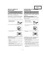
Lamp Replacement
Remplacement de la lampe
Note:
Remarque:
Since the lamp reaches a very high temperature
during units operation replacement of the lamp
should be done at least one hour after the power
has been turned off. (to allow the lamp to cool off.)
Installing the new lamp, make sure not to touch the
lamp (bulb) replace the lamp by holding its reflector
2.
[Use original replacement only.]
Comme la lampe devient très chaude pendant le
fonctionnement de l’unité, son remplacement ne doit
être effectué au moins une heure après avoir coupé
l’alimentation (pour permettre à la lampe de refroidir).
En installant la nouvelle lampe, s’assurer de ne pas
toucher la lampe (ampoule). Remplacer la lampe en
tenant son réflecteur 2.
[N’utiliser qu’un remplacement d’origine.]
1 Lampe
1 Lamp
2 Reflecteur
2 Reflector
DANGER ! –– Never turn the power on without the
lamp to avoid electric-shock or damage of the
devices since the stabilizer generates high voltages
at its start.
DANGER ! –– Ne jamais mettre sous tension sans
la lampe pour éviter un choc électrique ou des
dommages des appareils car le stabilisateur génère
de hautes tensions à sa mise en route.
Since small amounts of UV-radiation are emitted from
an opening between the exhaust fans, it is recommended to place the cap of the optional lens on the
opening during servicing to avoid eye and skin exposure.
Comme de petites quantités de radiation UV sont
émises par une ouverture entre les ventilateurs aspirants, il est recommandé de placer le capuchon
de l’optique optionnelle sur l’ouverture pendant
l’entretien pour éviter une exposition des yeux et la
peau.
6
PG-C20XU
PG-C20XE
AN-Z7T
WARNING:
High brightness light source, do not stare into the beam of light, or view directly. Be especially
careful that children do not stare directly in to the beam of light.
WARNING:
TO REDUCE THE RISK OF FIRE OR ELECTRIC SHOCK, DO NOT EXPOSE THIS UNIT TO
MOISTURE OR WET LOCATIONS.
CAUTION
The lighting flash with arrowhead within a
triangle is intended to tell the user that
parts inside the product are risk of electric
shock to persons.
RISK OF ELECTRIC SHOCK.
DO NOT REMOVE SCREWS
EXCEPT SPECIFIED USER
SERVICE SCREW
CAUTION: TO REDUCE THE RISK OF ELECTRIC SHOCK,
DO NOT REMOVE CABINET.
NO USER-SERVICEABLE PARTS EXCEPT LAMP UNIT.
REFER SERVICING TO QUALIFIED SERVICE
PERSONNEL.
The exclamation point within a triangle is
intended to tell the user that important
operating and servicing instructions are in
the manual with the projector.
CAUTION
CAUTION
CAUTION
(INLET Unit)
(INLET Unit)
(POWER Unit)
15A 250V
For continued
protection against
a risk of fire,
replace only with
same type 15A
250V fuse.
(F1701)
1A 250V
For continued
protection against a
risk of fire, replace
only with same type
2A 250V P100A, ANZEN
DENGU, 2A, 250V
103°C fuse.(TF701)
For continued
protection against
a risk of fire,
replace only with
same type 1A
250V fuse.
(F1702)
12345678901234567890123456789012123456789012345678901234567890121234567890123456789012345678901212
12345678901234567890123456789012123456789012345678901234567890121234567890123456789012345678901212
12345678901234567890123456789012123456789012345678901234567890121234567890123456789012345678901212
AVERTISSEMENT: Source lumineuse de grande intensité. Ne pas fixer le faisceau lumineux ou le regarder
directement. Veiller particulièrement à éviter que les enfants ne fixent directement le
faisceau lumineux.
AVERTISSEMENT: AFIN D’EVITER TOUT RISQUE D’INCENDIE OU D’ELECTROCUTION, NE PAS PLACER
CET APPAREIL DANS UN ENDROIT HUMIDE OU MOUILLE.
ATTENTION
L’éclair terminé d’une flèche à l’intérieur
d’un triangle indique à l’utilisateur que les
pi‘eces se trouvant dans l’appareil sont
susceptibles de provoquer une décharge
électrique.
RISQUE
D’ELECTROCUTION NE
PASRETIRER LES VIS, A
L’EXCEPTION DES VIS DE
REPARATION UTILISATEUR
SPECIFIEES
Le point d’exclamation à l’intérieur d’un
triangle indique à l’utilisateur que les
instructions de fonctionnement et
d’entretien sont détaillées dans les
documents fournis avec le projecteur.
ATTENTION: POUR EVITER TOUT RISQUE
D’ELECTROCUTION, NE PAS RETIRER LE CAPOT.
AUCUNE DES PIECES INTERIEURES N’EST REPARABLE
PAR L’UTILISATEUR, A L’EXCEPTION DE L’UNITE DE
LAMPE. POUR TOUTE REPARATION, S’ADRESSER A UN
TECHNICIEN D’ENTRETIEN QUALIFIE.
PRECAUTION
PRECAUTION
PRECAUTION
(Unite d’admission)
(Unite d’admission)
(Unité de PUTSSANCE)
15A 250V
Pour une protection
continue contre les
risques d’incendie,
ne remplacer
qu’avec un fusible
15A 250V du même
type.
(F1701)
1A 250V
Pour une protection
continue contre les
risques d’incendie,
ne remplacer
qu’avec un fusible
1A 250V du même
type.
(F1702)
Pour une protection
continue contre un
risques d’incendie, ne
remplacer qu’avec un
fusible P100A, ANZEN
2A 250V DENGU 2A 250V,
103°C du même type.
(TF701)
7
PG-C20XU
PG-C20XE
AN-Z7T
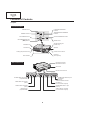
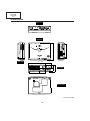
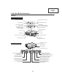
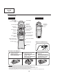
Location of Controls
Projector
Front and Top View
LAMP REPLACEMENT
indicator
ON/OFF button
ON/OFF
LAMP
TEMPERATURE WARNING
indicator
POWER
POWER indicator
TEMP.
KEYSTONE
INPUT/BACK button
INPUT
AUTO SYNC
BACK
ENTER
KEYSTONE/Adjustment
(]/[ )buttons
AUTO SYNC/ENTER button
MENU
MENU button
ZOOM knob
Air filter/Cooling fan
(Intake vent)
FOCUS ring
Speaker
Cooling fan (Exhaust vent)
Remote control sensor
Eyelet for
lens cap strap
Foot releases
Kensington Security
Standard connector
Side and Rear View
AC socket
Remote control sensor
INPUT 2
INPUT 3
S-VIDEO
VIDEO
AUDIO INPUT
(S-VIDEO, VIDEO INPUT)
INPUT 1
RS-232C
AUDIO
COMPUTER
OUTPUT (INPUT1)
AUDIO
COMPUTER
VIDEO INPUT 3 terminal
(RCA)
COMPUTER OUTPUT port
for INPUT 1
(HD 15)
AUDIO OUTPUT terminal
for INPUT 1
(3.5 mm stereo minijack)
AUDIO INPUT terminals
(RCA)
COMPUTER INPUT 1 port
(HD 15)
S-VIDEO INPUT 2 terminal
(4-pin Mini DIN)
AUDIO INPUT 1 terminal
(3.5 mm stereo minijack)
RS-232C port
(9-pin Mini DIN)
8
PG-C20XU
PG-C20XE
AN-Z7T
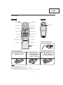
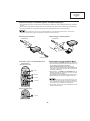
Remote Control
Rear View
Front View
Mouse (]/[)/
Adjustment (]/[)
buttons
Mouse (>)button
Mouse (<)button
POWER button
MOUSE button
RIGHT-CLICK/
ENTER button
FREEZE button
ENLARGE button
MENU button
AUTO SYNC button
INPUT button
AV MUTE button
KEYSTONE buttons
RESIZE button
VOLUME buttons
GAMMA button
LEFT-CLICK/
BACK button
Opening the Flip Cover
Flip cover
Inserting the Batteries
1
Press the tab and lift open
the battery cover in the
direction of the arrow.
2
Insert two AAA size
batteries,making sure
their polarities match the
+ and - marks inside
the battery compartment.
• If the remote control gets wet, wipe it dry immediately.
• Avoid excessive heat and humidity.
• If you will not be using the remote control for a long time, remove the batteries.
• Do not mix new and old or different types of batteries.
• There are operations that can only be carried out by remote control. Handle the remote control carefully.
9
3
Insert the tabs on the
end of the battery cover
into their slots and press
the cover into position.
PG-C20XU
PG-C20XE
AN-Z7T
Remote Control/Mouse Receiver Positioning
The remote control can be used to control the projector within the ranges shown below.
The remote mouse receiver can be used with the remote control to control the mouse functions of a connected
computer within the ranges shown below.
The signal from the remote control can be reflected off a screen for easy operation. However, the effective distance of the
signal may differ due to the screen material.
Controlling the Projector
Using the Wireless Mouse
Remote control
Remote control
23’ (7 m)
30ß
30ß
30ß
30ß
45ß
13’ (4 m)
45ß
120ß
Remote
mouse
receiver
30ß
Remote control
Using as a Wireless Mouse
Effective buttons in MOUSE mode
When MOUSE is pressed, the buttons on the remote
control light up and the remote control enters MOUSE
mode.
During MOUSE mode, the cursor can be used as the
pointer. MOUSE mode is for about ten seconds while
the buttons are lighting.
When MENU or ENLARGE is pressed, MOUSE mode
is released to the normal mode.
Be sure the supplied remote mouse receiver is
connected to your computer.
Remote control
(Front view)
Mouse
MOUSE
The wireless mouse may not operate correctly if your
computer serial port is not correctly set up. Refer to the
computer s operation manual for details of setting up/
installing the mouse driver.
For one-button mouse systems, use either the LEFT-CLICK
or RIGHT-CLICK button.
RIGHT-CLICK
AV MUTE
Remote control
(Rear view)
LEFT-CLICK
10
PG-C20XU
PG-C20XE
AN-Z7T
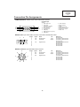
Connection Pin Assignments
COMPUTER INPUT 1 Port: 15-pin mini D-sub female connector
Computer Input
1
6
11
5
10
15
Analog
1. Video input (red)
2. Video input
(green/sync on green)
3. Video input (blue)
4. Not connected
5. Composite sync
6. GND (red)
7. GND (green/sync on green)
8. GND (blue)
9. Not connected
10.Not connected
11. GND
12.Bi-directional data
13.Horizontal sync signal
14.Vertical sync signal
15.Data clock
RS-232C Port: 9-pin D-sub male connector of the DIN-D-sub RS-232C cable
1
Pin No.
1
2
3
4
5
6
7
8
9
5
6
9
Signal
Name
RD
SD
Receive Data
Send Data
SG
Signal Ground
I/O
Input
Output
Reference
Not connected
Connected to internal circuit
Connected to internal circuit
Not connected
Connected to internal circuit
Not connected
Not connected
Not connected
Not connected
RS-232C Terminal: 9-pin Mini DIN female connector
8
7
9
3
6
4
5
2
Pin No.
1
2
3
4
5
6
7
8
9
Signal
Name
RD
SD
Receive Data
Send Data
SG
Signal Ground
1
11
I/O
Input
Output
Reference
Not connected
Connected to internal circuit
Connected to internal circuit
Not connected
Connected to internal circuit
Not connected
Not connected
Not connected
Not connected
PG-C20XU
PG-C20XE
AN-Z7T
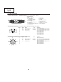
Dimensions
Rear View
8 5/32 (207)
6 43/64 (169.5)
Top View
Side View
2 9/ 32 (58)
315/64 (82)
5
4 21/32 (118)
Front View
/16 (8)
1 21/32 (42) 1 17/64 (32)
10 15/64 (260)
Bottom View
Unit: inches (mm)
12
PG-C20XU
PG-C20XE
AN-Z7T
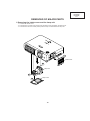
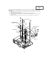
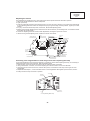
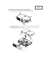
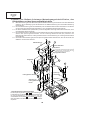
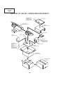
REMOVING OF MAJOR PARTS
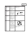
1. Removing the intake cover and the lamp unit.
1-1. Detach the intake cover.
1-2. Remove the one lock screw (silver) from the lamp cover and detach the lamp cover.
1-3. Remove the two lock screws (silver) from the lamp unit and detach the lamp unit.
1-1
Intake cover
1-3
Lamp unit
1-3
Lamp cover
1-2
13
PG-C20XU
PG-C20XE
AN-Z7T
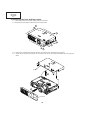
2. Removing the front and top panels
2-1. Remove the three lock screws (silver) from the front panel.
2-2. Remove the seven lock screws (silver) from the top panel.
2-2
2-2
2-2
2-2
2-1
2-3. Press the ❈-marked spots of the top panel to unhook the claws, and detach the top panel.
2-4. Slowly lift the top panel, disconnect the connectors from the control panel and speaker, and lift up the top
panel.
Top panel
2-4
2-3
Front Panel
14
PG-C20XU
PG-C20XE
AN-Z7T
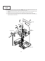
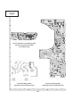
3. Removing the output PWB unit, remote control receiver PWB unit and intake
fan unit
3-1. Remove the five lock screws (yellow) from the output PWB unit. Remove the grounding spring and the
electrostatic sheet (PG-C20XU only).
3-2. Lift the output PWB unit, disconnect the connectors and lift up the output PWB unit.
3-3. Remove the two lock screws (black) from the intake fan unit and detach both the intake fan unit and the
temperature sensor.
3-4. Unhook the claws of the intake fan unit off the remote control receiver PWB unit, and detach this unit.
3-1
Grounding spring
3-1
Electrostatic sheet
(PG-C20XU Only)
(P1702)
(P1707)
Temperature sensor
(P1703)
(SC1102)
(SC1202)
Remote control
receiver PWB
Output PWB
3-3
(P1705)
(P1708)
(P1706)
(SC1302)
(P1704)
(P1601)
(P1602)
(P1701)
3-2
3-4
Intake fan unit
15
PG-C20XU
PG-C20XE
AN-Z7T
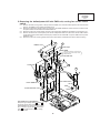
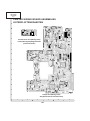
4. Removing the front duct unit, PC I/F PWB units, and optical mechanism unit
4-1. Remove the lock screw (silver) from the bimetal and detach the bimetal.
4-2. Remove the two lock screws (one in black, the other in silver) from the front duct unit and detach the front
duct unit.
4-3. Remove the two lock screws (yellow) from the PC I/F PWB unit. Detach this unit from above.
4-4. Remove the two lock screws (silver) from the lamp socket holder and detach the lamp socket holder.
4-5. Remove the four lock screws (two in black, two in yellow) from the optical mechanism unit and detach the
optical mechanism unit from above.
4-3
4-5
PC I/F PWB
unit
4-5
4-1
4-4
4-5
Optical
mechanism
unit
Front duct unit
4-2
Bottom panel
16
PG-C20XU
PG-C20XE
AN-Z7T
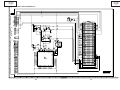
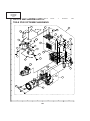
5. Removing the ballast/power/AC inlet PWB unit, cooling fan and AC select
switch
5-1. Remove the lock screw (yellow or silver) from the ballast cover. Peel the Teflon tape that secures the lead
wires on the ballast cover. Detach the ballast cover.
5-2. Remove the three lock screws (yellow or silver) from the ballast PWB unit. Disconnect the connectors from
the power PWB unit and detach the ballast PWB unit.
5-3. Remove the two lock screws (silver) from the cooling fan/power PWB unit and detach the cooling fan unit.
5-4. Remove the three lock screws (silver) from the AC inlet/power PWB unit. Disconnect the AC select switch
connectors and the power PWB connector (EA). Detach the AC inlet PWB unit, power PWB unit and power
PWB unit cover.
5-5. Remove the two lock screws (yellow) from the AC select switch and detach the switch, slide and spring.
5-1
Ballast cover
5-1
Teflon tape
Ballast PWB
5-2
(
Note: Be careful when connecting this
connector close to the live part of the
ballast PWB unit.
AC inlet PWB unit
Cooling fan
5-3
5-4
B
A
5-5
5-4
AC select switch
Power PWB unit
Slide
Power PWB unit cover
Spring
(EA)
❋ Precautions in reassembling
Keep the high-voltage leads ( A and B in
the figure) of the lamp socket on the
ballast PWB out of contact with the cooling
fan. To do this, lay the lead B behind the
lead A and dress them up in the cooling
fan holder notch.
17
)
PG-C20XU
PG-C20XE
AN-Z7T
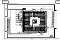
6. Removing the connecting terminals/3-dimensional Y/C separation PWB unit
assembly
6-1. Remove the two lock screws (yellow) and the two supports from the connecting terminals/3-dimensional Y/
C separation PWB unit assembly. Slide the PWB unit and draw the terminals out of the bottom plate.
6-2. Disconnect the connector (EA) from the connecting terminals PWB unit.
7. Removing the center duct and the PBS fan
7-1. Remove the one lock screw (yellow) from the center duct and detach the center duct.
7-2. Remove the one lock screw (yellow) from the PBS fan and detach the angle and the PBS fan.
6-1
7-1
Center duct
7-2
Angle
(EA)
6-2
Connecting terminals/
3-dimensional
Y/C separation PWB
unit assembly
PBS fan
18
PG-C20XU
PG-C20XE
AN-Z7T
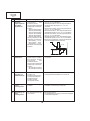
Resetting the TOTAL LAMP TIMER
● Resetting the total lamp timer
When replacing the lamp, reset the total lamp timer in the procedure below.
1
Connect the power cord.
Plug the power cord into the AC
socket of the projector.
2
Reset the lamp timer.
1 Press KEYSTONE ' and
KEYSTONE " on the projector at
the same time.
2 Press INPUT and AUTO SYNC on
the projector at the same time.
3 Press AUTO SYNC and MENU at
the same time until unit comes on.
LAMP 0000H is
displayed, indicating that
the lamp timer is reset.
1
INPUT
2
AUTO SYNC
BACK
ENTER
MENU
3
LAMP 0000H
● Light source (lamp)
The lamp used for light source has a service life of about 1,000 hours. If the total operating time exceeds 900
hours, replace the lamp with new one (separately sold) as soon as possible. However, if the image becomes
dim or the colors get less crisp even before the total operating time does not exceeds 900 hours, also replace
the lamp. The lamp's total operating time can be checked on the screen. If noticeable color irregularities are
found after replacing the lamp, make the color irregularity correction on page 28.
CAUTION
Intense light hazard. Do not attempt to look into the aper ture and lens while the projector is operating.
As the usage environment can vary significantly, the projector lamp may not operate for 1,000 hours.
"1,000 hours" above indicates average life span and should be used for r eference only. This is different than the warranty period.
For safety, the power will not be tur ned on from the fourth times when turning on the power without changing the lamp after use for 1,000
hours.
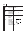
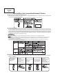
Maintenance Indicator
TEMPERATURE
WARNING
indicator
LAMP
REPLACEMENT
indicator
POWER indicator
Condition
The internal
temperature is
abnormally high.
Problem
Possible Solution
Blocked air intake.
Relocate the projector to an area with proper
ventilation.
Clogged air filter.
Clean the filter.
Cooling fan breakdown.
Internal circuit failure.
Take the projector to your nearest Authorized
Sharp Industrial LCD Products Dealer or
Service Center for repair.
The indicator flashes in
red.
Cooling down.
Wait until the indicator stops flashing and
turns off.
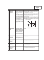
The lamp does not
illuminate.
Burnt-out lamp.
Lamp cir cuit failure.
The lamp requires
replacement.
Lamp has been used for
over 900 hours.
Carefully replace the lamp.
Take the projector to your nearest Authorized
Sharp Industrial LCD Products Dealer or
Service Center for repair.
The indicator flashes in
red when the projector
is on.
The filter cover is open.
Securely install the filter cover.
● Replacing the air filter
Just when replacing the lamp, replace also the air filter with the one that comes with the lamp replacement kit.
1.Disconnect the power 2.Remove the filter cover. 3.Remove the air filter.
4.Replace the air filter.
Turn over the projector. 1 Remove the air filter 1 Put the new air filter
cord.
into position.
stopper.
Unplug the power cord Press the tab and remove
2 Put the air filter stopper
the filter cover in the direc- 2 Remove the air filter.
from the AC socket.
back into position.
tion of the arrow.
1
r
1
2
2
19
5.Replace the filter cover.
Insert the tab on the end of
the filter cover into the filter
cover opening and press
the filter cover into
position.
PG-C20XU
PG-C20XE
AN-Z7T
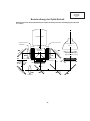
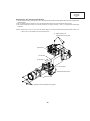
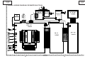
THE OPTICAL UNIT OUTLINE
Layout for proper setup of the optical components and parts (top view)
Projection Lens
Input polarizer B
Input polarizer R
Light source
(Lamp)
Relay lens 3
LCD(R)
LCD(B)
or
R
,G
,B
-c
AL
Cross dichroic prism
M5
d
te
oa
M6
R
or
M
irr
irr
m
Fly-eye lens (Input)
F1
Condencer lens R
UV absorbing glass
LCD(G)
Input polarizer G
G02
PBS
Red
L3
Relay lens 2
Fly-eye lens (Output)
L2
G03
L1
,G
,B
Condencer lens G
20
at
ed
AL
-c
o
or
ct
Relay lens 1
le
M2
f
re
M3
or
ct
G01
R
Green/Blue
le
f
re
,B
,G
R
Blue
M4
G
or
irr
M
m
irr
or
R
Green
M1
PG-C20XU
PG-C20XE
AN-Z7T
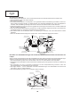
Adjusting the mirrors
This adjustment is needed when any of the optical parts of the optical mechanism has been replaced.
1. Disconnect the flat cables from all the LCD panels.
2. Light up the lamp.
3. Project a white-light image and check to see if there is any color tint in any direction. If any, loosen the incident-light
fly-eye adjusting plate lock screws and readjust the fly-eye to get the image uniformly whitish. Tighten up the lock
screws.
4. If by any chance the above step 3 fails, use the M1, M4 and M5 adjusting levers.
5. Before moving the M5 adjusting lever, shield the G and B color beams. (For shielding them, use reflective sheets
that reflect the incident lights.)
6. Loosen the adjusting lever lock screws, make adjustments, and tighten up the lock screws.
7. Before moving the M4 adjusting lever, shield the R and G color beams.
Front
Shielding plate for B
M5 Adjusting lever
Shielding plate for R
Lock screws
(yellow)
Lock screws
(yellow)
incident-light fly-eye
adjusting plate
Lock screws
(yellow)
Lock screws
(yellow)
M4 Adjusting lever
M1 Adjusting lever
Shielding plate for G
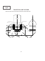
Correcting color irregularities on white-only screen when replacing the lamp
If color irregularities are found at the right and left on a white-only screen after replacing the lamp, it is necessary to
readjust the optical axis of the new lamp. Take the following steps.
1. Open the lamp cover and loosen the screws A, B and C at the bottom of the lamp.
2. Using a screwdriver or the like, move the U-shaped groove at the window D in the arrow direction.
3. Temporarily fix the screws A, B and C, close the lamp cover, and check the white-only screen again for color
irregularities.
4. Repeat the above steps 1, 2 and 3 until there will be no color irregularities. Now tighten up the screws A, B and C.
5. Finally secure the lamp cover back in position.
Screw A
Screw B
Screw C
D
Lamp assembly (bottom view)
21
PG-C20XU
PG-C20XE
AN-Z7T
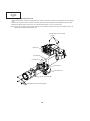
Replacing the prism holder unit
1. Remove the three lock screws, and take the prism holder unit and the projection lens assembly out of the optical
unit.
2. Remove the four lock screws, separate the prism holder unit and the projection lens assembly from each other.
3. Replace the prism holder unit with new one. Take the above steps 1 and 2 in reverse order.
Note: Even if just one of the LCD panels is defective, it is necessary to replace the entire prism holder unit. Do not
replace just the defective LCD panel only.
1Prism holder unit lock screws
(yellow)
Optical unit
G-LCD panel
R-LCD panel
B-LCD panel
Prism holder unit
Projection lens assembly
2Projection lens lock screws (yellow)
22
PG-C20XU
PG-C20XE
AN-Z7T
ELECTRICAL ADJUSTMENT
Hook up a signal generator, or a DOSV or Mac personal computer to the projector in order to feed the
signals specified in the Adjusting conditions.
ADJUSTMENT PRECAUTIONS
1 Precautions for initializing
It takes 5 seconds to get the memory initialized and the initial settings rewritten. To go through the initialization, the
onscreen display background on the process menu screen turns red and the message "INITIALIZE" appears
onscreen for 5 seconds after pressing the specified key. Finally turn off the AC power (unplug the power cord).
2 Initial factory settings (S4, S5)
It takes 5 seconds to get the initial factory settings written. Do not turn off the main power during this procedure. To
ensure this waiting time, "S4" or "S5" appears on the onscreen display for 5 seconds. When this sign disappears,
you can keep on the power or turn it off.
3 Video adjustment
Be careful not to cut off the signals during the video adjustment.
No.
Adjusting point
Adjusting conditions
Adjusting procedure
1
EEPROM
initialization
1. Turn on the power (with the
lamp on) and warm up the
set for 15 minutes.
2. Select the following group,
sub-group and subject.
Group : Option
Sub-group:
EEPROM Initialize
Subject : Initialize Start
» Make the following settings.
Press SW1601 to call the process mode. Initialize
the EEPROM by execution of Initialize Start. (After
the execution of Initialize Start, the EEPROM will not
be initialized unless the power is once turned off.)
2
Brightness
adjustment
1. Feed the XGA 10-step signal.
2. Select the following group,
sub-group and subjects.
Group : Adjust PC Image
Sub-group: AD
Subject :
R-Bright (In R adjustment)
G-Bright (In G adjustment)
B-Bright (In B adjustment)
3. Connect the synchroscope
(0.2V/div.) to the following
TPs.
In R adjustment TP1403
In G adjustment TP1402
In B adjustment TP1401
» Adjust the setting just until the color tone level 0 starts
moving.
23
0-gradation
0.8Vp-p
10-gradation
PG-C20XU
PG-C20XE
AN-Z7T
No.
3
4
5
Adjusting point
Drive adjustment
Panel input
signal amplitude
adjustment
Sample hold
pulse phase
checking
Adjusting conditions
Adjusting procedure
1. Feed the XGA 10-step signal.
2. Select the following group,
sub-group and subjects.
Group : Adjust PC Image
Sub-group: AD
Subject :
R-Contrast (In R adjustment)
G-Contrast (In G adjustment)
B-Contrast (In B adjustment)
3. Connect the synchroscope
(0.2V/div.) to the following
TPs.
In R adjustment TP1403
In G adjustment TP1402
In B adjustment TP1401
» First reach a setting where the color tone level 10
gets saturated. Then decrease the setting by one
point.
1. Select the following group,
sub-group and subjects.
Group : Adjust PC image
Sub-group: CXA2111R
Subject :
AMP-R-GAIN (In R adjustment)
AMP-R-BLK (In R adjustment)
AMP-G-GAIN (In G adjustment)
AMP-G-BLK (In G adjustment)
AMP-B-GAIN (IN B adjustment)
AMP-B-BLK (IN B adjustment)
2. Connect the synchroscope
to the following TPs.
In R adjustment TP1101
In G adjustment TP1201
In B adjustment TP1301
3. Feed the XGA 10-step signal.
1.Select AMP-R-GAIN and adjust the signal amplitude
to 3.8 ± 0.1. Select 0.1Vp-p.
2.Select AMP-R-BLK and adjust the white-white signal amplitude to 2.1 ± 0.1Vp-p.
Note: Make sure that the black side does not interfere
in GAIN adjustment.
Adjust the amplitude as for G and B in the same
procedure.
1. Feed the XGA mode monochrome signal.
2. Select the following group,
sub-group and subjects.
Group : LCD2(6050)
Sub-group: CLDLY
Subject : R_CLDLY
G_CLDLY
B_CLDLY
R_REVCLDLY
G_REVCLDLY
B_REVCLDLY
» Feed the G (30%) signal to see if there is no vertical
stripe visible on the screen. If it is visible, adjust the
setting to somewhere between 160 and 200.
Make also sure that the R and B settings are as follows.
R_CLDLY
171
R_REVCLDLY 175
B_CLDLY
175
B_REVCLDLY 178
24
0-gradation
0.8Vp-p
10-gradation
2.1Vp-p
3.8Vp-p
PG-C20XU
PG-C20XE
AN-Z7T
No.
Adjusting point
Adjusting conditions
Adjusting procedure
6
RGB
countervoltage
adjustment
1. Feed the countervoltage
adjustment signal. (XGA)
2. Select the following group,
sub-group and subjects.
Group : LCD2 (6050)
Sub-group: COM
Subject :
R_LCCOM (In R adjustment)
G_LCCOM (In G adjustment)
B_LCCOM (In B adjustment)
R_REVLCCOM (In R reverse adjustment)
G_REVLCCOM (In G reverse adjustment)
B_REVLCCOM (In B reverse adjustment)
» Using the set's control switch or the remote controller’s button, adjust the setting so that the flickering
be minimum.
» Adjust the setting so that the image comes to the
center of the screen.
7
RGB tone
reproduction
adjustment
1. Feed the green-only
SMPTE pattern signal.
(XGA)
2. Select the following
group, sub-group and
subject.
Group : Adjust PC Image
Sub-group: CXA2111R
Subject : AMP-BLK
» Adjust the AMP-BLK setting so that the gradation of
the part 1 (white 95% and 100%) as shown in the
figure below is barely discernible.
» Make sure that the gradation of the part 2 (black
0% and 5%) is also discernible.
2
1
8
RGB white
balance adjustment
1. Feed the 32-step grayscale signal. (XGA)
2. Select the following group,
sub-group and subjects.
Group : Adjust PC Image
Sub-group: CXA2111R
Subject : AMP-R-BLK
(In R adjustment)
AMP-B-BLK
(In B adjustment)
» Adjust the setting to achieve the best color tone
balance.
9
Horizontal
center adjustment
1. Feed the NTSC
monoscope signal.
2. Select the following
group, sub-group and
subject.
Group : Adjust VIDEO Image
Sub-group: VPC3230
Subject : H-Position
» Make sure the setting is 52.
25
PG-C20XU
PG-C20XE
AN-Z7T
No.
Adjusting point
Adjusting conditions
Adjusting procedure
10
Video BRIGHTNESS adjustment
1. Feed the NTSC 10-step
signal.
2. Select the following group,
sub-group and subject.
Group : Adjust VIDEO Image
Sub-group: VPC3230
Subject : Bright
» Make sure the setting is as shown below.
PG-C20XU ........ 142
PG-C20XE ........ 145
11
Video CONTRAST adjustment
1. Feed the NTSC 10-step
signal.
2. Select the following group,
sub-group and subject.
Group : Adjust VIDEO Image
Sub-group: VPC3230
Subject : Contrast
3. Connect the synchroscope
to TP1402.
» First reach a setting where the color tone level 10
gets saturated. Then decrease the setting by one
point.
0-gradation
0.8Vp-p
10-gradation
12
Color saturation
adjustment
1. Feed the color bar signal.
2. Select the following group,
sub-group and subject.
Group : Adjust VIDEO Image
Sub-group: VPC3230
Subject : Color
13
PSIG adjustment
1. Select the following group,
sub-group and subjects.
Group : Adjust VIDEO image
Sub-group: CXA2111R
Subject : PRGLEV
SIDLEV
2. Connect the synchroscope
to TP1210.
3. Using the NTSC 10-step
input signal, make sure that
there is no vertical stripes
appearing every 12 dots. (If
white or black vertical
stripes appear, fine-adjust
the SIDLEV setting.)
26
» Make sure the setting is 128.
PSIG
» Make sure the setting is as shown below.
PRGLEV ........... 61
SIDLEV ............. 170
PG-C20XU
PG-C20XE
AN-Z7T
No.
Adjusting point
14
VIDEO panel
input signal
amplitude
adjustment
Adjusting conditions
Adjusting procedure
1. Select the following group,
sub-group and subjects.
Group : Adjust VIDEO image
Sub-group: CXA2111R
Subject :
AMP-R-Gain (In R adjustment)
AMP-R-BLK (In R adjustment)
AMP-G-Gain (In G adjustment)
AMP-G-BLK (In G adjustment)
AMP-B-Gain (IN B adjustment)
AMP-B-BLK (IN B adjustment)
2. Connect the synchroscope
to the following TPs.
In R adjustment TP1101
In G adjustment TP1201
In B adjustment TP1301
3. Feed the NTSC 10-step
signal.
1.Select AMP-R-Gain and adjust the signal amplitude
to 3.8 ± 0.1Vp-p.
2.Select AMP-R-BLK and adjust the white-white signal amplitude to 2.1 ± 0.1Vp-p.
3.Select AMP-G-Gain and adjust the signal amplitude
to 3.5 ± 0.1Vp-p.
4.Select AMP-G-BLK and adjust the white-white signal amplitude to 2.6 ± 0.1Vp-p.
5.Select AMP-B-Gain and adjust the signal amplitude
to 3.5 ± 0.1Vp-p.
6.Select AMP-B-BLK and adjust the white-white signal
amplitude to 2.6 ± 0.1Vp-p.
Note: Make sure that the black side does not interfere
in Gain adjustment.
2.1Vp-p(R)
3.8Vp-p(R)
15
Video white
balance adjustment
1. Feed the 32-step grayscale signal. (VIDEO)
2. Select the following group,
sub-group and subjects.
Group : Adjust VIDEO Image
Sub-group: CXA2111R
Subject :
AMP-R-BLK (In R adjustment)
AMP-B-BLK (In B adjustment)
» Adjust the setting to achieve the best color tone balance.
16
Automatic color
irregularity
correction
1. Apply the automatic color
correction using the automatic color irregularity correction system.
» Make sure that no remarkable uneven color remains
on the screen.
17
Color-related
performance
checking
1. Feed the color bar signal.
» User adjustment:
Check the Color and Tint settings.
18
Video-related
performance
checking
1. Feed the monoscope pattern signal.
» User adjustment:
Check the performance relating to Contrast, Brightness and Sharpness.
19
Audio-related
performance
checking
1. Feed the audio signal.
» User adjustment:
Check the sound volume performance.
27
PG-C20XU
PG-C20XE
AN-Z7T
No.
Adjusting point
Adjusting conditions
Adjusting procedure
20
RGB-related
performance
checking
1. Feed the RGB signal.
» User adjustment:
Check the performance relating to Contrast, Brightness, Red, Blue, Clock, Phase, H-POS, and V-POS.
21
DVD performance checking
1. Receive the 480I signal.
» User adjustment:
Check the performance relating to Contrast, Brightness, Color, Tint and Sharpness.
22
Thermistor
performance
checking
1. Heat the thermistor with a
hair dryer.
» Make sure that the temperature is indicated.
23
Auto sync
performance
checking
1. Feed the phase check pattern signal.
» In the VGA, SVGA, XGA, and SXGA modes, make
sure the Clock, Phase, H-Pos and V-Pos settings can
be automatically adjusted.
24
Keystone correction performance checking
» Make sure that the keystone distortion can be corrected.
25
Lamp power
changeover
performance
checking
» Make sure that the brightness can be changed with
the user lamp power control.
26
Delivery settings
» Make the following settings.
Destination Process adjustment
(Model)
28
Remote control adjustment
US (XU)
S4
Factory setting at 4
Europe (XE)
S4
Factory setting at 4
PG-C20XU
PG-C20XE
AN-Z7T
Process menu1
Group
Sub group
Subject
R-Bright
R-Contrast
G-Bright
AD
G-Contrast
B-Bright
B-Contrast
AMP-R-BLK
Adjust PC Image
AMP-R-GAIN
AMP-G-BLK
AMP-G-GAIN
AMP-B-BLK
CXA2111R
AMP-B-GAIN
AMP-BLK
AMP-GAIN
Bright
Contrast
Color
VPC3230
H-Position
AGC
AMP-R-BLK
AMP-R-Gain
Adjust VIDEO Image
AMP-G-BLK
AMP-G-Gain
CXA2111R
AMP-B-BLK
AMP-B-Gain
CLPLVL
PRGLEV
SIDLEV
Bright
VPC3230
Contrast
Color
AMP-R-Gain
AMP-G-Gain
Adjust Component (480I)
AMP-B-Gain
AMP-R-BLK
CXA2111R
AMP-G-BLK
AMP-B-BLK
LCD5(CXA1839)(480P)
(The menu appears on the screen. But do not use this menu because
this model is not equipped with the DTV function.)
DTV_Bright
DTV_Contrast
DTV_Color
DTV_Tint
NRS-H
NRS-L
NRS
R_LCCOM
G_LCCOM
LCD2 (6050)
B_LCCOM
R_REVLCCOM
COM
G_REVLCCOM
B_REVLCCOM
29
PG-C20XU
PG-C20XE
AN-Z7T
Process menu2
Group
Sub group
Subject
R_CLDLY
LCD2 (6050)
G_CLDLY
B_CLDLY
CLDLY
R_REVCLDLY
G_REVCLDLY
B_REVCLDLY
R_GHOST
G_GHOST
B_GHOST
GHOST
R_GHOST_W
G_GHOST_W
LCD3 (Adjust GA4)
B_GHOST_W
RCK-PHASE
CK-PHASE
GCK-PHASE
BCK-PHASE
R_HCONV
G_HCONV
B_HCONV
R_REVHCONV
Adjust Horz. Conv
G_REVHCONV
B_REVHCONV
LCD4 (Adjust Conv)
R_VCONV
G_VCONV
B_VCONV
Adjust Vert. Conv
R_REVVCONV
G_REVVCONV
B_REVVCONV
Boot Code
Config
Sharp Table
Version
Rom Code
GUI
Sub CPU
S4
SS
S5
Inside Temp/ref
Temp
Outside Temp/ref
Lamp Fan
Temp/Fan State
Fan Speed
Other Fan
on/off
Gamma Off
Option
Revise Color Uneven
on/off
Cancel
EEPROM Initialize
Initialize Start
30
PG-C20XU
PG-C20XE
AN-Z7T
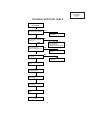
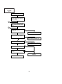
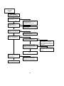
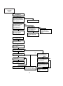
TROUBLE SHOOTING TABLE
Checking the basic
performance
Is the POWER LED on or
flickering in red or green?
NO
Go to "Checking the
power unit"
YES
Is the set turned on by the
set’s or remote controller’s
power key?
NO
Go to "Checking the
microcomputer
peripherals" and
"Checking the PLL circuit"
YES
Is the cooling fan
running? Is the lamp on?
NO
Go to "Checking the lamp
light-up"
YES
NO
Is the user menu
displayed?
YES
Go to "Checking the
output line"
Go to "Checking the RGB
input"
Go to "Checking the
component input"
Go to "Checking the
video input"
Go to "Checking the
audio input"
Go to "Checking the RS232C"
End
31
PG-C20XU
PG-C20XE
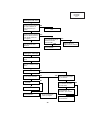
AN-Z7T
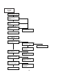
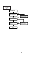
Checking the power unit
Are the connectors CN751, NO
P1707 and P3701 inserted
completely?
Insert the connectors
CN751, P1707 and
P3701 tightly?
YES
Is the lamp cover closed
completely?
NO
Close the lamp cover
tightly.
YES
Is the bimetal switch off?
NO
YES
Is AC voltage (100-240V)
applied between pins (1)
and (3) of CN703?
Replace the bimetal
NO
Replace F701.
YES
Disconnect the CN751
connector (EA). Is there
13V output at pins (7), (8)
and (9)?
YES
NO
Check Q706, Q708 and
Q710 for damage.
Replace as required.
Check the output PWB for
short-circuit. Check also
the UNT3701 on the
connection terminal PWB
and its peripheral circuits.
32
PG-C20XU
PG-C20XE
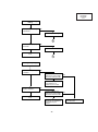
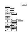
AN-Z7T
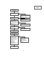
Checking the
microcomputer
peripherals
Is a voltage of about 3V
applied to pin (33) (RCS)
of IC1601?
NO
Check the intake filter
cover for poor fitting and
the cooling fan for trouble.
YES
Is SW1602 set at
"NORMAL" position?
NO
Set SW1602 to
"NORMAL" position.
YES
Is there pulse signal at
pin (64) of IC1601?
NO
Check IC1601, IC1606 and
their peripheral circuits.
YES
Is there pulse signal at pin
(1) of IC1601?
NO
Is the signal level at pin
(7) of IC8037 about 0V?
YES
YES
NO
Check all the signals (A1
thru A17 and D1 thru D15) NO
of IC8021 with oscilloscope.
Are signal levels 0V and
3V?
YES
End
Is there signal at pins (1),
(3), (4) and (6) of IC1802?
YES
NO
Check all the ICs
connected with the
SDA3/SCL3 and
SDA5/SCL5 lines.
End
33
Check IC8018, IC8019,
IC8020 and their peripheral
circuits as well pin (26) of
IC1601 and its peripheral
circuits.
Check IC8021 and
IC8022. Replace the PC
interface as required.
PG-C20XU
PG-C20XE
AN-Z7T
Checking the PLL circuit
Is there 120MHz clock
output at pin (8) of
IC8001?
YES
NO
Is there 40MHz clock
output at pin (9) of
IC8001?
YES
NO
Is there 16MHz or so
clock output at pin (7) of
IC8001?
NO
IC8001 or its peripheral
circuit defective.
YES
End
Checking the lamp
light-up
Turn on the power switch.
Is discharge sound heard
from the lamp?
YES
Is the lamp socket
disconnected?
YES
NO
Reconnect the lamp
socket tightly.
Are DC260-400V voltages
applied between the pins
of PL connector?
NO
Go to "Checking the
power unit".
YES
Is the BA harness tightly
inserted? Is the harness
broken?
NO
Insert the BA harness
tightly. Or replace it as
required.
YES
Is voltage of over 1V
applied between pins (1)
and (2) of BA harness?
YES
NO
Go to "Checking the
microcomputer
peripherals".
Replace the ballast unit.
34
NO
Replace the lamp.
PG-C20XU
PG-C20XE
AN-Z7T
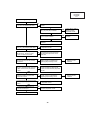
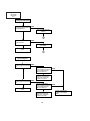
Checking the output line
Are there video input signals at
TP1401, TP1402 and TP1403?
NO
Check P8001 and SC1701 for solder
cracks.
YES
Are there video output signals at pins YES
(42), (44) and (46) of IC8024?
Check Q8013, Q8014,
Q8015 and their
peripheral circuits.
NO
Are there digital input signals at pins
(1) thru (33) of IC8024?
YES
Check IC8024 and
IC8025.
NO
IC8023 defective. Replace the PC
interface.
Are there video output signals at
pins (14), (16) and (18) of IC1405?
NO
Check IC1405, IC1403 and their
peripheral circuits.
YES
Are there video input signals at pins
(45) of IC1101, IC1201, IC1301,
IC1102, IC1202 and IC1302?
NO
Check IC1102, IC1202, IC1302 and
their peripheral circuits as well as
pins (35) and (36) and the 15.5V
power line.
YES
Are there clock input signals (MCLK) at
pins (54) and (55) of IC1102, IC1202
and IC1302?
NO
Check P8001 and SC1701 for solder
cracks, and go to "Checking the
digital signal processing circuit".
Are there output signals at pins (17),
(19), (21), (28), (30) and (32) of IC1101, NO
IC1201, IC1301, IC1102, IC1202 and
IC1302?
Check IC1101, IC1201, IC1301,
IC1102, IC1202, IC1302, IC1401,
IC1403, IC1405 and their peripheral
circuits.
IC8023 defective.
Replace the PC
interface.
YES
YES
Are signals going to the control signal
lines at pins (3) thru (21) of IC1103,
IC1203 and IC1303?
NO
Check P8001 and SC1701 for solder
cracks, and go to "Checking the
digital signal processing circuit".
NO
Check IC1402, IC1404 and their
peripheral circuits.
NO
Check SC1101, SC1202, SC1301
and their peripheral circuits.
YES
Are signals coming from the control signal
lines at pins (11) thru (17) of IC1402 and
IC1404?
YES
Are there input signals at SC1101,
SC1201 and SC1301?
YES
Check the R, G and B panels.
35
IC8023 defective.
Replace the PC
interface.
PG-C20XU
PG-C20XE
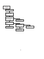
AN-Z7T
Checking the RGB input
Feed the sync separation RGB
signal to INPUT1 terminal (pin
(15) of D-SUB).
1
Select INPUT1 (RGB) with the
set’s control or remote control
button.
2
Is the image disturbed? Does
NO SIGANL indication
appear?
NO
Go to "Checking the sync signal".
YES
Do R, G and B colors appear?
NO
Go to "Checking the RGB input".
YES
Does an image appears?
YES
Go to "Checking the input signal
setting input".
NO
Is the contour as specified?
NO
YES
Are there disturbing vertical
stripes?
NO
YES
IC8026 or peripheral circuit
defective.
End
36
PG-C20XU
PG-C20XE
AN-Z7T
Checking the input signal
setting
Is the input signal setting
as specified?
NO
Select the specified signal.
YES
2
Is the connector properly
connected?
NO
Reconnect the connector.
YES
End
1
Checking the sync signal
Is there vertical sync signal
at TP8003?
NO
Is there horizontal sync
signal at pin (3) of IC3008
connection terminal PWB?
YES
NO
YES
IC3008 or its peripheral
circuit defective. Or
SC3003 in poor contact.
Is there horizontal sync
signal at TP8002?
YES
NO
Is there horizontal sync
signal at pin (3) of IC3006
connection terminal PWB?
NO
YES
End
IC3006, IC3010 or their
peripheral circuit defective.
Or SC3003 in poor
contact.
37
SC3001 or its peripheral
circuit defective.
PG-C20XU
PG-C20XE
AN-Z7T
Checking the RGB signal
In order to check the input
signal, set the signal
generator to the gradation
signal.
Using the oscilloscope,
measure the lands (R, G
YES
and B inputs of IC8026) of
C8204, C8208 and C8213.
Are there specified
NO
Are there gradation signals NO
at pins (8), (10) and (12) of
IC8012?
YES
IC8012 or its peripheral
circuit defective.
IC8026 or its peripheral
circuit defective.
Are there gradation signals NO
at pins (16), (18) and (20)
of IC3002 connection
terminal PWB?
YES
IC3002 or its peripheral
circuit defective. Or
SC3003 in poor contact.
38
SC3001 or its peripheral
circuit defective.
PG-C20XU
PG-C20XE
AN-Z7T
Checking the SOG circuit
Using the oscilloscope,
measure the land of R8231 YES
(pin (32) of IC8026). Is
there composite sync
signal?
End
NO
Using the oscilloscope,
measure the land of R8110
(base of Q8010). Does the
video signal contain the
sync signal?
NO
Is there video signal with
sync signal at pin (18) of
IC3002 connection
terminal PWB?
YES
IC8008, IC8009, IC8031 or
their peripheral circuit
defective.
YES
NO
IC3002 connection
terminal PWB or its
peripheral circuit defective.
SC3003 or its peripheral
circuit defective.
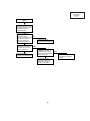
Checking the video input
Feed the specified video
signal.
Select VIDEO with the
set’s key or remote control
button.
Does an image appear?
NO
YES
YES
YES
Is the image disturbed?
Is there video signal at pin
(73) of IC8003?
NO
Are the colors as
specified?
NO
NO
Is there video signal at pin
(7) of IC3403 connection
terminal PWB?
YES
YES
End
IC3403 or its peripheral
circuit defective. Or
SC3003 in poor contact.
IC8003 or its peripheral
circuit defective.
Go to "Checking the
video sync signal".
J3303 or its peripheral
circuit defective.
39
NO
PG-C20XU
PG-C20XE
AN-Z7T
Checking the video sync
signal
Using the oscilloscope,
measure the signal at
TL8006. (Check the
vertical sync signal.)
Is the vertical sync signal
as specified?
NO
YES
Using the oscilloscope,
measure the signal at
TL8009. (Check the
horizontal sync signal.)
Is the horizontal sync
signal as specified?
NO
Go to "Checking the input
signal setting".
YES
If out of spec again,
IC8003 or its peripheral
circuit defective.
Is there 15kHz or so signal NO
at TP8007?
YES
Is there signal with half the
vertical frequency at
TP8010?
NO
YES
Is there 27MHz or so clock
signal at FL8034?
NO
YES
Is there 13.5MHz or so
clock signal at FL8034?
NO
IC8003 or its peripheral
circuit defective.
YES
End
40
PG-C20XU
PG-C20XE
AN-Z7T
Checking the digital signal
processing circuit
Is there 40MHz or so clock
signal at FL8024?
NO
Go to "Checking the PLL
circuit".
YES
Is there 38kHz or so pulse
(sync) signal at FL8026?
NO
YES
Is there 60Hz or so pulse
(sync) signal at FL8025?
NO
IC8022, IC8021 or their
peripheral circuit defective.
YES
End
41
PG-C20XU
PG-C20XE
AN-Z7T
Checking the audio
signal
Are there audio output
signals at pins (7) of
IC3301 and IC3302?
NO
YES
Is voltage applied to pin (4)
of IC1901?
NO
YES
Using the remote control,
change VOL and cancel
MUTE. Does the voltage at
pin (7) of IC1901 vary
accordingly?
Check R1914 first and
then the power circuit.
NO
Check IC1403, IC1605 and
their peripheral circuits.
YES
Is there audio output signal
at pin (5) of IC1901?
Check the audio cable.
Switch IC3301 and IC3302
to each other to check the
peripheral circuits.
NO
YES
Check IC1901 and its
peripheral circuits.
Check the SP connector.
Checking the RS-232C
Using the communication
software ("TERA TERM"
recommended), make the
following settings:
Baud rate: 9600 bps
Bit length: 8 bits
Stop bit: 1 bit
Parity: None
Press the RETURN key on
the keyboard. Does "ERR"
reappear?
NO
Check IC3601, IC1606,
IC1601, SW1602, IC8022,
communication circuit and
their peripheral circuits.
YES
End
42
PG-C20XU
PG-C20XE
AN-Z7T
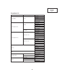
Technische Daten
Produkttyp
Modell
Videosystem
Wiedergabeverfahren
LCD-Projektionspaneel
Objektiv
Projektionslampe
Kontrastverh ä ltnis
Videoeingangssignal
S-Videoeingangssignal
Horizontale Aufl ö sung
Audioausgang
RGB-Computereingangssignal
Punktetakt
Vertikale Frequenz
Horizontale Frequenz
Computereingangs-Signal
Lautsprechersystem
Nennspannung
Eingangsspannung
Nennfrequenz
Nennaufnahme
Betriebstemperatur
Lagertemperatur
Geh ä use
I/R-Tr ä gerfrequenz
Abmessungen (ca.)
Gewicht (ca.)
Mitgeliefertes Zubehör
Ersatzteile
LCD Projector
PG-C20XU/XE
PAL/PAL 60/PAL-M/PAL-N/SECAM/NTSC 3.58/NTSC 4.43/DTV 480P
LCD-Projektionspaneel x 3,optisches RGB-Verschlußverfahren
Panelgröße:22,9 mm (0,9") (13,9 mm [H ] x 18,5 mm [B ])
Wiedergabe-Verfahren:Durchl ä ssiges TN-Flüssigkristall-Paneel
Treiberverfahren:TFT (Dünnfilmtransistor) Aktivmatrix-Paneel
Anzahl der Bildpunkte:786.432 Bildpunkte (1.024 [H ] x 768 [V ])
1 –1,2 Zoomobjektiv, F2,3 –2,6, f =36,0 –43,2 mm
150 W Gleichstrom-Lampe
500:1
RCA-Stecker:VIDEO, Gemischtes Video, 1,0 Vs-s, negatives Sync.-Signal, 75 Ω terminiert
RCA-Stecker:AUDIO, 0,5 Vrms mehr als 22 kΩ (Stereo)
4-Pin Mini DIN-Stecker
Y (Luminanz-Signal):1,0 Vs-s,negatives Sync.-Signal, 75 Ω terminiert
C (Chrominanz-Signal):Stoß 0,286 Vs-s, 75 Ω terminiert
580 Fernsehzeilen (Videoeingang)
1,0 W (monaural)
15-PIN MINI D-SUB STECKANSCHLUSS (Computer-Eingangsport 1 (COMPUTER INPUT 1),
Computer-Ausgangsport für Eingangs-Port 1 (COMPUTER OUTPUT für INPUT 1):
RGB getrennt/gemischte Sync./Sync.auf Grün-Typ analoger Eingang:0 –0,7 Vs-s,
positiv,75 Ω terminiert
STEREO-MINIBUCHSE:AUDIO,0,5 Vrms,mehr als 22 kΩ (Stereo)
HORIZONTALES SYNC.-SIGNAL:TTL-Pegelsignal (positiv/negativ)oder gemischtes Sync.Signal (nur Macintosh)
VERTIKALES SYNC.-SIGNAL:Wie oben
12 –108 MHz
43 –85 Hz
15 –80 kHz
9-Pin Mini DIN-Steckanschluß (RS-232C-Anschlußstelle)
2,8 cm (1 7 ⁄64" ) rund
100 –240 V Wechselstromspannung
2,6 A
50/60 Hz
230 W (Wahl von "OFF" im "Energiespar-Modus".)
200 W (Wahl von "ON" im "Energiespar-Modus".)
+5°C bis +35°C
−20°C bis +60°C
Kunststoff
38 kHz
260 x 74 x 207 mm (B x H x T) (nur Hauptgerät)
260 x 82 x 207 mm (B x H x T) (einschlie ß lich Drehfüße und vorstehende Teile)
2,6 kg
Fernbedienung, Zwei Batterien der Größe AAA,Netzkabel (3,6 m), RGB-Computerkabel (3 m),
Computer-Audiokabel (3 m), PS/2-Maus-Steuerungskabel (1 m), USB-Maus-Steuerungskabel (1,5
m), DIN-D-Sub RS-232C-Kabel (15 cm), Fernbedienungs-Mausempfänger, Ersatz-Luftfilter,
Objektivkappe (angebracht), Objektivkappenband, CD-ROM, Bedienungsanleitung für LCDProjektor, Kurzanleitungen für den LCD-Projektor
Lampensatz (Lampe/Käfigmodul)(BQC-PGC20X//1), Fernbedienung (RRMCG1613CESA),
Batterien der Größe AAA,Netzkabel (CACCU5013DE01 (PG-C20XU), QACCV4002CEZZ (PGC20XE), QACCB5024CENA (PG-C20XE)), RGB-Computerkabel (QCNWG0002EZZ), Computer-Audiokabel (QCNW-4870CEZZ), PS/2-Maus- Steuerungskabel (QCNW-5113CEZZ), USBMaus-Steuerungskabel (QCNW-5680CEZZ), DIN-D-Sub RS-232C-Kabel (QCNW-5288CEZZ),
Fernbedienungs-Mausempfänger (RUNTK0694CEZZ), Luftfilter (PFILD0123CEZZ), Objektivkappe
(PCOVZ1095CEKA), Objektivkappenband (UBNDT0013CEZZ), CD-ROM (UDSKA0029CEN1
(PG-C20XU), UDSKA0048CEN1 (PG-C20XE)), Bedienungsanleitung für LCD-Projektor (TINS7204CEZZ (PG-C20XU), TINS-7271CEZZ (PG-C20XE)), Kurzanleitungen für den LCD-Projektor
(TINS-7205CEZZ (PG-C20XU), TINS-7272CEZZ (PG-C20XE), TINS-7284CEZZ (PG-C20XE),
TINS-7285CEZZ (PG-C20XE))
Dieser Projektor von SHARP ist mit 3 LCD-(Flüssigkristallanzeige)
Projektionspaneels ausgestattet. Diese neuartigen Projektionspaneels
enthalten TFTs (Dünnfilmtransistoren) mit insgesamt 786.432
Bildpunkten ( x RGB). Bei allen technologisch fortschrittlichen,
elektronischen Geräten, z.B.Großbild-Fernsehern, Videosystemen bzw.
Videokameras,sind bestimmte Toleranzgrenzen für die Funktionen
gegeben.
Dieses Gerät hat einige inaktive,innerhalb akzeptierter Toleranzgrenzen
liegende TFTs, die als beleuchtete oder als nicht aktive Punkte auf der
Bildwand wiedergegeben werden. Dies hat keinen Einfluß auf die
Bildqualität und die Lebensdauer des Gerätes.
Ä nderungen der technischen Daten ohne vorherige Ank ü ndigung vorbehalten.
43
PG-C20XU
PG-C20XE
AN-Z7T
HINWEIS FÜR DAS
WARTUNGSPERSONAL
12345678901234567890123456789012123456789012345
12345678901234567890123456789012123456789012345
Auswechseln der Lampe
12345678901234567890123456789012123456789012345
ACHTUNG: UV-STRAHLUNG
12345678901234567890123456789012123456789012345
12345678901234567890123456789012123456789012345
Hinweis:
Da die Lampe während des Betriebs sehr heiß wird,
sollte die Lampe erst ausgewechselt werden, nachdem
das Gerät mindestens eine Stunde ausgeschaltet war,
damit die Lampe ausreichend abkühlen kann.
Beim Installieren der neuen Lampe muß darauf
geachtet werden, die Lampe selbst (Glaskolben)
nicht zu berühren. Vielmehr muß die Lampe am
Reflektor 2 gehalten werden.
[Es darf nur ein Original-Ersatzteil verwendet
werden.]
Die Beleuchtungsquelle des LCD-Projektors, eine
UHP-Lampe, emittiert eine geringe Menge
UV-Strahlung.
DIREKTE BESTRAHLUNG AUF AUGEN
UND HAUT MUSS VERMIEDEN WERDEN.
Zur Gewährleistung der Sicherheit muß folgendes
beachtet werden:
1 Lampe
1. Bei Arbeiten am Projektor bei eingeschalteter
Lampe und abgenommenem oberen Gehäuse muß
unbedingt eine Sonnenbrille getragen werden.
2 Reflektor
GEFAHR! — Niemals die Spannungsversorgung
einschalten, ohne daß eine Lampe vorhanden ist,
um elektrische Schläge und Schäden am Gerät zu
vermeiden, da der Stabilisator anfangs hohe
Spannungen erzeugt.
2. Die Lampe darf nicht außerhalb des
Lampengehäuses eingeschaltet werden.
Da eine geringe Menge UV-Strahlung an der Öffnung
zwischen den Lüftern austritt, wird empfohlen,
während der Wartungsarbeiten die Abdeckkappe des
Zusatzobjektivs an dieser Öffnung anzubringen, um
Augen und Haut vor den UV-Strahlen zu schützen.
3. Betrieb für länger als 2 Stunden bei
abgenommenem Gehäuse ist nicht zulässig.
Zur Beachtung bei UV-Strahlung
und Mitteldruck-Lampen
1. Vor dem Auswechseln der Lampe muß der
Netzstecker gezogen werden.
2. Vor Durchführung von Wartungsarbeiten muß das
Gerät eine Stunde abkühlen.
3. Die Lampe darf nur gegen eine der gleichen Art
ausgewechselt werden. Typ BQC-PGC20X//1,
bemessen für 100 V/200 W.
4. Die Lampe gibt eine geringe UV-Strahlung ab,
daher muß direkter Augenkontakt vermieden
werden.
5. Die Mitteldruck-Lampe weist ein Explosionsrisiko
auf. Daher müssen die nachstehenden
Installationsanweisungen beachtet werden, und die
Lampe muß vorsichtig behandelt werden.
44
PG-C20XU
PG-C20XE
AN-Z7T
Lage der Bedienelemente
Projektor
Ansicht von vorne und oben
Lampenaustausch-Anzeige
Betriebs-Taste (ON/OFF)
ON/OFF
Betriebs-anzeige
LAMP
POWER
Temperaturwarnanzeige
TEMP.
KEYSTONE
Eingang-/Zur ü ck-Taste
(INPUT/BACK)
Trapezverzeichnungs-/
Einstellungs-Tasten
(KEYSTONE/]/[)
INPUT
BACK
Automatische
Synchronisierung-/EingabeTaste (AUTO SYNC/ENTER)
AUTO SYNC
ENTER
MENU
Menü-Taste (MENU)
Luftfilter/Kühlventilator
(Lufteinlaß)
Zoom-Knopf
Lautsprecher
Fokussierring
Fernbedienungs-Sensor
Kühlventilator (Luftauslaß)
Öffnung für
Objektivkappenband
Drehfuß-Feststeller
Standardanschluß für
KensingtonSicherheitssperre
Seiten-und Rückansicht
Steckanschluß
Fernbedienungs-Sensor
INPUT 2
INPUT 3
AUDIO INPUT
S-VIDEO
VIDEO (S-VIDEO, VIDEO INPUT)
L
R
RS-232C
INPUT 1
AUDIO
COMPUTER
OUTPUT (INPUT 1)
AUDIO
COMPUTER
Computer-Ausgangspor t für
Eingangs-Port 1 (HD 15)
(COMPUTER OUTPUT ür
f INPUT 1)
S-Videoeingangsanschlu ß 2
(4-Pin Mini DIN)
(S-VIDEO INPUT 2)
Audioausgangsanschluß für EingangsPort 1 (3.5 mm stereo minijack)
(AUDIO OUTPUT für INPUT 1)
Videoeinganganschluß 3
(RCA) (VIDEO INPUT 3)
Audioeingangsanschlüsse
(RCA) (AUDIO INPUT)
Computer-Eingangs-Port 1
(HD 15)(COMPUTER INPUT 1)
Audioeingangsanschluß 1
(3,5 mm Stereo-Minibuchse)
(AUDIO INPUT 1)
RS-232C-Anschlußstelle
(9-Pin Mini DIN)
45
PG-C20XU
PG-C20XE
AN-Z7T
Fernbedienung
Ansicht von hinten
Vorderansicht
Maus-(]/[)/
Einstellungs-(]/[)
Tasten
Maustaste (> )
Netz-Taste
(POWER)
Maustaste (< )
Rechte Klick-/
Eingabe-Taste
(R-CLICK/ENTER)
MAUS-Taste
(MOUSE)
Linke Klick-/
Zurück-taste
(L-CLICK/
BACK)
Vergrößern-Taste
(ENLARGE)
Standbild-Taste
(FREEZE)
Auto-Synchron-Taste
(AUTO SYNC)
Menü-Taste
(MENU)
AV-StummschaltungsTaste (AV MUTE)
Eingangs-Taste
(INPUT)
TrapezverzeichnungsTasten (KEYSTONE)
Größe-Taste (RESIZE)
Lautstärke-Tasten
(+/−)
GAMMA-Taste
Öffnen der Abdeckung
Abdeckung
Einsetzen der Batterien
1
•
•
•
•
•
Auf den Vorsprung
drücken und die
Batteriefachabdeckung in
Pfeilrichtung öffnen.
2
Zwei Batterien der Größe
AAA einlegen und
sicherstellen, daß die Pole
mit der + und −
Markierung im Batteriefach
übereinstimmen.
Vorsprünge auf dem
3 Die
Ende der
Batteriefachabdeckung in
die Schlitze schieben und
die Abdeckung auf das
Batteriefach drücken.
Wenn die Fernbedienung na ß wird, sollte sie sofort trocken gewischt wer den.
Die Fernbedienung sollte nicht übermäßiger Wärme oder Feuchtigkeit ausgesetzt wer den.
Wenn die Fernbedienung f ür längere Zeit nicht verwendet wird, sollten die Batterie entfernt wer den.
Niemals neue und alte Batterien oder verschiedene Batterietypen mischen.
Einige Bedienvorgänge können nur mit der Fernbedienung ausgef ührt werden. Die Fernbedienung sor gfältig behandeln.
46
PG-C20XU
PG-C20XE
AN-Z7T
Positionierung der Fernbedienung bzw. des Mausempfängers
Die Fernbedienung kann zur Steuerung des Projektors innerhalb des unten gezeigten Bereiches verwendet
werden.
Der Fernbedienungs-Mausempfänger kann mit der Fernbedienung zusammen zur Steuerung der Mausfunktion
eines angeschlossenen Computers innerhalb des unten gezeigten Bereiches verwendet werden.
Das Signal der Fernbedienung kann für einen einfacheren Betrieb von der Bildwand reflektiert werden. Der wirksame
Abstand des Signals kann aufgrund des Materials der Bildwand unterschiedlich sein.
Steuerung des Projektors
Verwendung der drahtlosen Maus
Fernbedienung
Fernbedienung
7m
30
30
30
30
45
120
4m
FernbedienungsMausempfänger
45
30
Fernbedienung
Verwendung als eine drahtlose Maus
Verwendbare Tasten in der MOUSE-Betriebsart
Beim Drücken von MOUSE leuchten die Tasten auf
der Fernbedienung auf und die Fernbedienung wird
auf die MOUSE-Betriebsart eingestellt.
Während der MOUSE-Betriebsart kann der Cursor als
Zeiger verwendet werden. Die MOUSE-Betriebsart
wird etwa 10 Sekunden während des Aufleuchtens
der Tasten eingestellt.
Beim Drücken von MENU oder ENLARGE wird die
MOUSE-Betriebsart beendet und die normale
Betriebsart wieder eingestellt.
Sicherstellen, daß der mitgelieferte FernbedienungsMausempfänger am Computer angeschlossen ist.
Fernbedienung
(Ansicht von vorne)
Maus
MOUSE
R-CLICK
Die drahtlose Maus kann nicht richtig funktionieren, wenn
der serielle Port des Computers nicht richtig eingestellt ist.
Siehe die Bedienungsanleitung des Computers für Hinweise
zur Einstellung bzw. Installation des Maustreibers.
Für eintastige Systeme kann sowohl L-CLICK als auch RCLICK verwendet werden.
AV MUTE
Fernbedienung
(Ansicht der Rückseite)
L-CLICK
47
PG-C20XU
PG-C20XE
AN-Z7T
Pin-Belegung
Computer-Eingangsport 1 (COMPUTER INPUT 1): 15-Pin Mini-D-Sub-Buchse
1
6
11
5
10
15
Computereingang
Analog
1. Videoeingang (rot)
2. Videoeingang
(Grün/Sync. auf Grün)
3. Videoeingang (blau)
4. Nicht belegt
5. Gemischtes Sync.-Signal
6. MASSE (rot)
7. MASSE (Grün/Sync. auf Grün)
8. MASSE (blau)
9.
10.
11.
12.
13.
Nicht belegt
Nicht belegt
MASSE
Bi-direktionale Daten
Horizontales Sync.Signal
14. Vertikales Sync.-Signal
15. Daten-Zeitgeber
RS-232C-Anschlußstelle: 9-Pin D-Sub-Stecker des DIN-D-Sub RS-232C-Kabels
Pin Nr.
1
2
3
4
5
6
7
8
9
5
1
9
6
Signal
Name
E/A
RD
SD
Daten empfangen
Daten senden
SG
Signalerdung
Eingang
Ausgang
Referenz
Nicht angeschlossen
An internen Schaltkreis angeschlossen
An internen Schaltkreis angeschlossen
Nicht angeschlossen
An internen Schaltkreis angeschlossen
Nicht angeschlossen
Nicht angeschlossen
Nicht angeschlossen
Nicht angeschlossen
RS-232C-Anschlußstelle: 9-Pin Mini DIN-Steckanschluß
8
7
9
6
3
5
4
2
Pin Nr.
1
2
3
4
5
6
7
8
9
Signal
Name
E/A
RD
SD
Daten empfangen
Daten senden
SG
Signalerdung
1
48
Eingang
Ausgang
Referenz
Nicht angeschlossen
An internen Schaltkreis angeschlossen
An internen Schaltkreis angeschlossen
Nicht angeschlossen
An internen Schaltkreis angeschlossen
Nicht angeschlossen
Nicht angeschlossen
Nicht angeschlossen
Nicht angeschlossen
PG-C20XU
PG-C20XE
AN-Z7T
Abmessungen
Ansicht der Rückseite
207
169,5
Ansicht von oben
Seitenansicht
Ansicht von vorne
118
8
42
82
32
260
58
Anhang Ansicht von unten
Einheit:mm
49
PG-C20XU
PG-C20XE
AN-Z7T
ENTFERNEN DER HAUPTTEILE
1. Abnehmen der Einlaßabdeckung und der Lampen-Einheit.
1-1. Die Einlaßabdeckung abnehmen.
1-2. Die Halteschraube aus der Lampenabdeckung herausdrehen, dann die Lampenabdeckung abnehmen.
1-3. Die beiden Halteschraube aus der Lampen-Einheit herausdrehen, dann die Lampen-Einheit ausbauen.
1-1
Einlaßabdeckung
1-3
Lampen-Einheit
1-3
Lampenabdeckung
1-2
50
PG-C20XU
PG-C20XE
AN-Z7T
2. Abnehmen der vorderen und oberen Verkleidungen
2-1. Die drei Halteschrauben (silberfarben) aus der vorderen Verkleidung herausdrehen.
2-2. Die sieben Halteschrauben (silberfarben) aus der oberen Verkleidung herausdrehen.
2-2
2-2
2-2
2-2
2-1
2-3. Die mit ∗ markierten Stellen der oberen Verkleidung nach unten drücken, um die Haken zu lösen; danach die
obere Verkleidung abnehmen.
2-4. Die obere Verkleidung vorsichtig anheben, die Stecker von der Steuertafel und dem Lautsprecher abziehen,
dann die obere Verkleidung nach oben abnehmen.
Oberen Verkleidungen
2-4
2-3
Vorderen Verkleidungen
51
PG-C20XU
PG-C20XE
AN-Z7T
3. Ausbau der Platine-Ausgabeeinheit, des Fernbedienungs-Sensors, der
Platine-Empfängereinheit für die Fernbedienung und der Lüfter-Einheit
3-1. Die fünf Halteschrauben (gelb) aus der Platine-Ausgabeeinheit herausdrehen.Die Massefeder und die
elektrostatische Schutzfolie entfernen.
3-2. Die Platine-Ausgabeeinheit anheben, die Stecker abziehen, dann die Platine-Ausgabeeinheit herausheben.
3-3. Die beiden Halteschrauben (schwarz) aus der Ansaug-Lüftereinheit herausdrehen, dann die
Ansaug-Lüftereinheit und den Temperatursensor ausbauen.
3-4. Die Haken der Ansaug-Lüftereinheit von der Fernbedienungsempfänger-Platineneinheit lösen, dann diese
Baugruppe herausnehmen.
3-1
Massefeder
3-1
Elektrostatische Schutzfolie
(PG-C20XU)
(P1702)
Temperatursensor
(P1707)
(P1703)
PlatineAusgabeeinheit
(SC1102)
3-3
(P1705)
(P1708)
(P1706)
(SC1202)
PlatineFernbedienungsempfängerseinheit
(SC1302)
(P1704)
(P1601)
(P1602)
(P1701)
3-2
3-4
Lüfter-Einheit
52
PG-C20XU
PG-C20XE
AN-Z7T
4.Ausbau der vorderen Luftführungseinheit, PC-I/F-platine und der
Optik-Einheit
4-1. Die Halteschraube (silberfarben) aus dem Bimetall herausdrehen, dann das Bimetall abnehmen.
4-2. Die beiden Halteschrauben (eine schwarze und eine silberfarbene) aus der vorderen Luftführungseinheit
herausdrehen, dann die vordere Luftführungseinheit ausbauen.
4-3. Die beiden Halteschrauben (gelb) aus der PC-I/F-platine herausdrehen. Die PC-I/F-platine von oben
herausnehmen.
4-4. Die beiden Halteschrauben (silberfarben) aus dem Lampenfassungshalter herausdrehen, dann den
Lampenfassungshalter ausbauen.
4-5. Die vier Halteschrauben (zwei schwarze und zwei gelbe) aus der Optik-Einheit herausdrehen, dann die
Optik-Einheit von oben herausnehmen.
4-3
4-5
PC-I/Fplatine
4-5
4-1
4-4
4-5
Optik-Einheit
4-2
Untere Verkleidung
53
PG-C20XU
PG-C20XE
AN-Z7T
5. Ausbau der Ballast-/Leistungs-/Netzeingangseinheit-Platine, des
Kühlgebläses und des Spannungswählschalters
5-1. Die Halteschraube (gelb oder silberfarben) aus der Ballast-Abdeckung herausdrehen. Das Teflon-Klebeband
entfernen, das zur Befestigung der Steckerkabel an der Ballast-Abdeckung dient. Die Ballast-Abdeckung
herausnehmen.
5-2. Die drei Halteschrauben (gelb oder silberfarben) aus der Ballast-Platineneinheit herausdrehen. Die Stecker
aus der Leistungs-Platineneinheit herausdrehen, dann die Ballast-Platineneinheit entfernen.
5-3. Die beiden Halteschrauben (silberfarben) aus der Kühlgebläse-/Leistungs-Platineneinheit entfernen, dann
die Kühlgebläse-Einheit ausbauen.
5-4. Die drei Halteschrauben (silberfarben) aus der Netzeingangs-/Leistungs-Platineneinheit herausdrehen. Die
Stecker des Spannungswählschalters und der Leistungs-Platineneinheit (EA) abziehen. Die
Netzeingangs-Platineneinheit, Leistungs-Platineneinheit und die Abdeckung der Leistungs-Platineneinheit
herausnehmen.
5-5. Die beiden Halteschrauben (gelb) aus dem Spannungswählschalter herausdrehen, dann den Schraube, das
Gleitstück und die Feder entfernen.
5-1
Ballastabdeckung
5-1
Teflon-Klebeband
Ballast-Platine
5-2
(
Hinweis: Beim Anschluß dieses Steckers besonders
vorsichtig vorgehen, da die benachbarten Teile der
Ballast-Platineneinheit stromführend sind.
Eingangsplatinen-Einheit
Kühlgebläse
5-3
5-4
B
A
5-5
5-4
Spannungs
wählschalter
Leistungsplatinen-Einheit
Gleitstück
Abdeckung der
LeistungsplatinenEinheit
Feder
(EA)
∗Vorsichtshinweise zum Zusammenbau
Die Hochspannungskabel ( A und B in der Abbildung) der
Lampenfassung an der Ballast-Platineneinheit dürfen nicht
mit dem Kühlgebläse in Kontakt kommen. Um dies
sicherzustellen, ist das Kabel B hinter Kabel A zu verlegen,
dann die Kabel in den Einschnitt des Kühlgebläse-Halters
einpassen.
54
)
PG-C20XU
PG-C20XE
AN-Z7T
6. Ausbau der Anschlußklemmen-/ 3D Y/C-Trennplatinen-Einheit
6-1. Die beiden Halteschrauben (gelb) und die beiden Halterungen aus der Anschlußklemmen-/dreidimensionalen
Y/C-Trennplatinen-Einheit herausdrehen. Die Platineneinheit zur Seite schieben und die Anschlußklemmen
aus der Bodenplatte herausziehen.
6-2. Den Stecker (EA) von der Anschlußklemmen-Platineneinheit abziehen.
7. Ausbau der mittleren Luftführung und des PBS-Kühlgebläses
7-1. Die Halteschraube von der mittleren Luftführung herausdrehen, dann die mittlere Luftführung abnehmen.
7-2. Die Halteschraube aus dem PBS-Kühlgebläse herausdrehen, dann das Winkelstück und das PBS-Kühlgebläse
ausbauen.
6-1
7-1
7-2
Winkelstück
Mittlere
Luftführung
(EA)
6-2
Anschlußklemmen-/
3D Y/C-TrennplatinenEinheit
PBSKühlgebläse
55
PG-C20XU
PG-C20XE
AN-Z7T
Rückstellen des Lampenbetriebszeit-Timers
● Rückstellen des Lampenbetriebszeit-Timers
Nach dem Auswechseln der Lampe muß der Lampenbetriebszeit-Timer entsprechend den nachfolgenden
Anweisungen zurückgestellt werden.
● Lichtquelle (Lampe)
Die als Lichtquelle verwendete Lampe weist eine Lebensdauer von ungefähr 1000 Stunden auf. Nachdem die
Gesamtbetriebszeit mehr als 900 Stunden beträgt, muß die Lampe so bald wie möglich durch ein Neuteil ersetzt werden
(separat erhältlich). Wenn die Abbildung allerdings dunkel oder verschwommen erscheint, bevor die 900 Stunden erreicht
sind, muß die Lampe ersetzt werden. Die Gesamtbetriebszeit der Lampe wird am Display angezeigt. Wenn nach dem
Ersetzen der Lampe gewisse Farbabweichungen festgestellt werden, muß die auf Seite 58 beschriebene
Farbabweichungskorrektur vorgenommen werden.
CAUTION
• IGefährliche Lichtstrahlen. Niemals beim Betrieb des Projektors in die Öffnung oder das Objektiv schauen.
• Wenn die Betriebsumgebung große Unterschiede aufweist, kann die Verwendungdauer der Lampe weniger als 1.000 Stunden betragen.
• Die obige Angabe von "1.000 Stunden" bedeutet eine durchschnittliche Verwendungsdauer und ist nur als Referenz gedacht. Dies
unterscheidet sich von der Garantiezeit.
• Aus Sicherheitsgründen wird das Gerät nach dem Ausschalten nicht ein viertes Mal eingeschaltet, ohne daß die Lampe nach einer
Nutzungszeit von 1.000 Stunden ausgewechselt wird.
● Auswechseln des Luftfilters
Gleichzeitig mit dem Ersetzen der Lampe ist auch der Luftfilter durch das im Lampen-Ersatzteilesatz enthaltene
Neuteil zu ersetzen.
1. Das Netzkabel von
der abtrennen.
Das Netzkabel vom
Steckanschluß
abtrennen.
2.Die Filterabdeckung 3.Den Luftfilter entfernen. 4.Den Luftfilter anbringen.
entfernen.
Den Projektor umdrehen. 1 Den Luftfilterhalter 1 Den neuen Filter in
Auf den Vorsprung
entfernen.
die Halterung setzen.
drücken und die Filter2 Den Luftfilter
2 Den Luftfilterhalter
abdeckung in
entfernen.
wieder einsetzen.
Pfeilrichtung entfernen..
1
r
1
2
2
56
5.Die Filterabdeckung
anbringen.
IDie Lasche am Ende der
Filterabdeckung in die
Öffnung der Filterabdeckung einsetzen und
den Filter fest andrücken.
PG-C20XU
PG-C20XE
AN-Z7T
Beschreibung der Optik-Einheit
Erläuterungen für das korrekte Setup der optischen Komponenten und Baugruppen (Ansicht
von oben)
Projektionsobjektiv
Eingabe-polarisator B
Eingabe-Polarisator R
Beleuchtungsquelle
Relaislinse 3
(Lampe)
LCD(R)
LCD(B)
,G
,B
-be
sch
ich
M5
tet
er
ie
ge
lR
M6
AL
Zweifarbiges
Kreuzprisma
Sp
Fliegenaugenoptik (Eingang)
ieg
Sp
el
Sammellinse R
UV-Absorptionsscheibe
LCD(G)
Eingabe-Polarisator G
G02
PBS
Rot
L3
Relaislinse 2
Fliegenaugenoptik (Ausgang)
L2
G03
F1
R
L1
,G
,B
Sammellinse G
R
Grün
r
or
kt
le
o
kt
M2
ef
-R
le
ef
M3
Relaislinse 1
57
s
-be
AL
M1
te
ich
ch
R
Grün/Blau
-R
,B
G01
G
,G
lR
ge
ie
Sp
Blau
M4
l
ge
pie
S
ter
PG-C20XU
PG-C20XE
AN-Z7T
Einstellen der Spiegel
Diese Einstellung wird erforderlich, wenn eine der Komponenten des optischen Mechanismus ersetzt wurde.
1. Die Flachkabel von allen LCD-Tafeln abziehen.
2. Die Lampe einschalten.
3. Ein Weißlicht-Bild projizieren und überprüfen, ob in irgendeinem Bereich der Abbildung ein Farbton zu sehen ist.
Wenn Farbtöne angezeigt werden, die Halteschrauben der Lichteinfall-Gleitplatte lösen, dann die Gleitplatte so
einstellen, daß die Abbildung einfarbig weiß erscheint. Danach die Halteschrauben wieder festziehen.
4. Sollte die Einstellung nicht mit den in Schritt 3 gegebenen Anweisungen durchzuführen sein, sind die Einstellhebel
M1, M4 und M5 zu verwenden.
5. Bevor der Einstellhebel M5 bewegt wird, müssen die G- und B-Farbstrahlen abgeschirmt werden. (Zum Abschirmen
sind Reflexionsfolien zu verwenden, die einfallendes Licht reflektieren.)
6. Die Halteschrauben der Einstellhebel lösen, die Einstellungen vornehmen, dann die Halteschrauben wieder
festziehen.
7. Bevor der Einstellhebel M4 bewegt wird, müssen die R- und G-Farbstrahlen abgeschirmt werden.
Vorder
B-Abgeschirmtafel
Halteschrauben
(gelb)
M5 Einstellhebel
R-Abgeschirmtafel
Halteschrauben
(gelb)
LichteinfallGleitplatte
Halteschrauben
(gelb)
Halteschrauben
(gelb)
M4 Einstellhebel
M1 Einstellhebel
G-Abgeschirmtafel
Korrektur von Farbabweichungen auf einem Nur-Weiß-Bildschirm beim Auswechseln der
Lampe
Wenn im rechten und linken Bereich eines Nur-Weiß-Bildschirms nach dem Auswechseln der Lampe Farbabweichungen
auftreten, muß die optische Achse der neuen Lampe erneut einjustiert werden. Hierzu wie folgt vorgehen:
1. Die Lampenabdeckung öffnen, dann die Schrauben A, B und C im unteren Bereich der Lampe lösen.
2. Mit Hilfe eines Schraubendrehers oder eines ähnlichen Werkzeugs die U-förmige Rille in Fenster D in Pfeilrichtung
schieben.
3. Die Schrauben A, B und C provisorisch festdrehen und die Lampenabdeckung schließen, dann den
Nur-Weiß-Bildschirm auf Farbabweichungen überprüfen.
4. Die obigen Schritte 1, 2 und 3 wiederholen, bis keine Farbabweichungen mehr festzustellen sind. Danach die
Schrauben A, B und C wieder festziehen.
5. Die Lampenabdeckung wieder in der vorherigen Position anbringen.
Schraube A
Schraube B
Schraube A
D
Lampen-Einheit (Ansicht von unten)
58
PG-C20XU
PG-C20XE
AN-Z7T
Auswechseln der Prismenhalter-Einheit
1. Die drei Halteschrauben herausdrehen, dann die Prismenhalter-Einheit und die Objektiv-Einheit aus der Optik-Einheit
herausnehmen.
2. Die vier Halteschrauben entfernen, dann die Prismenhalter-Einheit und die Objektiv-Einheit trennen.
3. Die Prismenhalter-Einheit durch ein Neuteil ersetzen. Die obigen Schritte 1 und 2 in umgekehrter Reihenfolge
ausführen.
Hinweis: Selbst wenn auch nur eine der LCD-Tafeln defekt ist, muß die Prismenhalter-Einheit ersetzt werden. Auf
keinen Fall nur die defekte LCD-Tafel auswechseln.
1 Halteschrauben der
Prismenhalter-Einheit (gelb)
Optik-Einheit
G-LCD-Tafel
R-LCD-Tafel
B-LCD-Tafel
Prismenhalter-Einheit
Objektiv-Einheit
2 Halteschrauben der Objektiv-Einheit (gelb)
59
PG-C20XU
PG-C20XE
AN-Z7T
ELEKTRISCHE EINSTELLUNGEN
Einen Signalgenerator bzw. einen PC oder Macintosh-Computer an den Projektor anschließen, um die
Signale zuzuführen, die in den Einstellbedingungen aufgeführt sind.
ADJUSTMENT PRECAUTIONS
1 Vorsichtsmaßnahmen bei der Initialisierung
Es dauert nur 5 Sekunden, um den Speicher zu initialisieren und die Anfangseinstellungen zu überschreiben. Bei
der Initialisierung wechselt der Bildschirm-Hintergrund der Menüanzeige auf Rot, und die Meldung „INITIALIZE“
erscheint nach dem Betätigen der vorgeschriebenen Taste für 5 Sekunden am Bildschirm. Danach den
Geräteschalter ausschalten (und den Netzstecker abziehen).
2 Anfängliche Werkseinstellungen (S4, S5)
Es dauert 5 Sekunden, um die anfänglichen Werkseinstellungen zu schreiben. Während dieses Vorgangs darf
das Gerät nicht ausgeschaltet werden. Um diese Wartezeit sicherzustellen, erscheint "S4" und "S5" für 5 Sekunden
in der Anzeige. Nachdem dieses Symbol verschwindet, kann das Gerät eingeschaltet bleiben oder ausgeschaltet
werden.
3 Videoeinstellung
Sicherstellen, daß die Signale während der Videoeinstellung nicht unterbrochen werden.
Nr.
Einstellgegenstand
Einstellbedingungen
Einstellverfahren
1
EEPROM wird
initialisiert
1. Den Netzschalter
einschalten und das
Gerät für ca. 15 Minuten
vorwärmen lassen.
(Sicherstellen, daß die
Kontrollampe
aufleuchtet.)
2. Die folgende Gruppe,
Untergruppe und Position
wählen.
Gruppe: Option
Untergruppe:
EEPROM Initialize
Position: Initialize Start
» Die folgenden Einstellungen vornehmen:
SW1601 drücken, um den Prozeßmodus
aufzurufen. Das EEPROM initialisieren, indem
Initialize Start ausgeführt wird. (Nach der
Ausführung von Initialize Start ist es nicht
erforderlich, den EEPROM-Speicher erneut zu
initialisieren - es sei denn, die Stromversorgung
wird unterbrochen.)
2
Helligkeitseinstellung
1. Das XGA 10-Stufensignal
zuführen.
2. Die folgende Gruppe,
Untergruppe
bzw.
Positionen wählen.
Gruppe:Adjust PC Image
Untergruppe: AD
Position:
R-Bright(bei R-Einstellung)
G-Bright (bei G-Einstellung)
B-Bright(bei B-Einstellung)
3. Das Synchroskop (0,2
V-Teilung)
mit
den
folgenden TPs verbinden.
Bei R-Einstellung TP1403
Bei G-Einstellung TP1402
Bei B-Einstellung TP1401
» Die Einstellung gerade vornehmen, wo sich der 0Farbtonpegel bewegt.
60
0-Farbabstufung
0,8Vs-s
10-Farbabstufung
PG-C20XU
PG-C20XE
AN-Z7T
Nr.
Einstellgegenstand
3
Einstellung des
RGB-Antriebs
4
5
Einstellung der
Platinen-Eingangssignalamplitude
Muster- und
Halteimpulsphase
Einstellbedingungen
Einstellverfahren
1. Das XGA 10-Stufensignal
zuführen.
2. Die folgende Gruppe,
Untergruppe
bzw.
Positionen wählen.
Gruppe: Adjust PC Image
Untergruppe: AD
Position:
R-Contrast (bei R-Einstellung)
G-Contrast (bei G-Einstellung)
B-Contrast (bei B-Einstellung)
3. Das Synchroskop (0,2
V-Teilung)
mit
den
folgenden TPs verbinden.
Bei R-Einstellung TP1403
Bei G-Einstellung TP1402
Bei B-Einstellung TP1401
» Zuerst eine Einstellung vornehmen, wo sich der 10Farbtonpegel sättigt. Danach ist die Einstellung um
einen Punkt zu erniedrigen.
1. Die folgende Gruppe,
Untergruppe
bzw.
Positionen wählen.
Gruppe: Adjust PC Image
Untergruppe: CXA2111R
Position:
AMP-R-GAIN (Bei R-Einstellung)
AMP-R-BLK (Bei R-Einstellung)
AMP-G-GAIN (Bei G-Einstellung)
AMP-G-BLK (Bei G-Einstellung)
AMP-B-GAIN (Bei B-Einstellung)
AMP-B-BLK (Bei B-Einstellung)
2. Das Synchroskop mit den
folgenden TPs verbinden.
Bei R-Einstellung TP1101
Bei G-Einstellung TP1201
Bei B-Einstellung TP1301
3. Das XGA-10-Stufen-Signal
zuführen.
1.AMP-R-GAIN wählen, dann die Signalamplitude
auf 3,8 ± 0,1 einstellen. 0,1 Vs-s wählen.
2.AMP-R_BLK wählen, dann die
Weiß-Weiß-Signalamplitude auf 2,0 ± 0,1 Vs-s
einstellen.
Hinweis: Sich vergewissern, daß die Schwarzseite nicht
die GAIN-Einstellung behindert.
Die Amplituden für G und B sind auf die gleiche
Weise einzustellen.
1. Das Monochrom-Signal
des XGA-Modus zuführen.
2. Die folgende Gruppe,
Untergruppe
bzw.
Positionen wählen.
Gruppe: LCD2 (6050)
Untergruppe: CLDLY
Position: R_CLDLY
G_CLDLY
B_CLDLY
R_REVCLDLY
G_REVCLDLY
B_REVCLDLY
» Das G-Signal (30%) zuführen, um zu
sicherzustellen, daß der Bildschirm keinen
vertikalen Streifen aufweist. Falls dies der Fall ist,
die Einstellung innerhalb von 160 und 200
vornehmen.
Sicherstellen, daß R- und B-Einstellwerte wie folgt
sind:
R_CLDLY
171
R_REVCLDLY 175
B_CLDLY
175
B_REVCLDLY 178
61
0-Farbabstufung
0,8Vs-s
10-Farbabstufung
2,1Vs-s
3,8Vs-s
PG-C20XU
PG-C20XE
AN-Z7T
Nr. Einstellgegenstand
Einstellbedingungen
Einstellverfahren
6
Einstellung der
RGBGegenspannung
1. Ein GegenspannungsEinstellsignal im XGAModus zuführen
2. Die folgende Gruppe,
Untergruppe
bzw.
Positionen wählen.
Gruppe: LCD2 (6050)
Untergruppe: COM
Position:
R_LCCOM (Bei R-Einstellung)
G_LCCOM (Bei G-Einstellung)
B_LCCOM (Bei B-Einstellung)
R_REVLCOM (Bei
umgekehrter R-Einstellung)
G_REVLCOM (Bei
umgekehrter G-Einstellung)
B_REVLCOM (Bei
umgekehrter B-Einstellung)
» Den Steuerschalter des Geräts oder die Taste der
Fernbedienungseinheit verwenden, um die
Einstellung so vorzunehmen, daß das
Bildschirmflickern auf ein Minimum reduziert ist.
» Die Einstellung so vornehmen, daß sich das Bild im
Mittelpunkt des Bildschirms befindet.
7
Einstellung der
RGB-Farbtonwiedergabe
1. Ein Nur-Grün-SMPTE- Signal zuführen. (XGA)
2. Die folgende Gruppe,
Untergruppe
bzw.
Positionen wählen.
Gruppe: Adjust PC Image
Untergruppe: CXA2111R
Position: AMP-R-BLK
» Die AMP-BLK-Einstellung so vornehmen, daß die
Farbabstufung von Bereich 1 (95% und 100% weiß)
nur noch schwach erkennbar sind, wie in der
Abbildung gezeigt.
» Sich vergewissern, daß die Farbabstufung von
Bereich 2 (0% und 5% schwarz) noch erkennbar
ist.
2
1
8
RGBWeißbalance
1. Das 32-Stufen-GrauskalaSignal zuführen. (XGA)
2. Die folgende Gruppe,
Untergruppe
bzw.
Positionen wählen.
Gruppe: Adjust PC Image
Untergruppe: CXA2111R
Position:
AMP-R-BLK (Bei R-Einstellung)
AMP-B-BLK (Bei B-Einstellung)
» Die Daten einstellen, um die beste Farbtonbalance
zu erzielen.
9
Einstellung der
Horizontalmitte
1. Das NTSC-Monoskop-signal zuführen.
2. Die folgende Gruppe,
Untergruppe und Position
wählen.
Gruppe: Adjust VIDEO Image
Untergruppe: VPC3230
Position: H-Position
» Sicherstellen, das die Einstellung dem Wert 52
entspricht.
62
PG-C20XU
PG-C20XE
AN-Z7T
Nr.
Einstellgegenstand
Einstellbedingungen
Einstellverfahren
10
Einstellung der
Video-Helligkeit
(BRIGHTNESS)
1. Das NTSC 10-Stufensignal
zuführen.
2. Die folgende Gruppe,
Untergruppe und Position
wählen.
Gruppe: Adjust VIDEO Image
Untergruppe: VPC3230
Position: Bright
» Sicherstellen, daß die Einstellung der nachfolgenden
Beschreibung entspricht.
PG-C20XU ........ 142
PG-C20XE ........ 145
11
Einstellung des
Video-Kontrasts
(CONTRAST)
1. Das NTSC 10-Stufensignal
zuführen.
2. Die folgende Gruppe,
Untergruppe und Position
wählen.
Gruppe: Adjust VIDEO Image
Untergruppe: VPC3230
Position: Contrast
3. Das Synchroskop mit
TP1402 verbinden.
» Zuerst eine Einstellung vornehmen, wo sich der 10Farbtonpegel sättigt. Danach ist die Einstellung um
einen Punkt zu erniedrigen.
» Sicherstellen, das die Einstellung dem Wert 128
entspricht.
12
Einstellung der
Farbsättigung
1. Das
JA-8CH-Signal
zuführen.
2. Die folgende Gruppe,
Untergruppe und Position
wählen.
Gruppe: Adjust VIDEO Image
Untergruppe: VPC3230
Position: Color
3. Das Synchroskop mit
TP1403 verbinden.
13
PSIG-Einstellung
1. Die folgende Gruppe,
Untergruppe
bzw.
Positionen wählen.
Gruppe: Adjust VIDEO Image
Untergruppe: CXA2111R
Position: PRGLEV
SIDLEV
2. Das Synchroskop mit
TP1210 verbinden.
3. Das NTSC 10-Stufen-Eingangssignal zuführen und
dann sicherstellen, daß keine
vertikalen Streifen im Abstund
von jeweils 12 Punkten
erscheinen. (Wenn weiße
oder schwarze Vertikalstreifen erscheinen, muß die
SIDLEV-Einstellung
durchgeführt werden.)
63
0-Farbabstufung
0,8Vs-s
10-Farbabstufung
Mit SIDLEV einstellen.
PSIG
Mit PROGLEV einstellen.
» Sicherstellen, daß die Einstellung der nachfolgenden
Beschreibung entspricht.
PRGLEV ........... 61
SIDLEV ............. 170
PG-C20XU
PG-C20XE
AN-Z7T
Nr. Einstellgegenstand
14
Einstellung der
Eingangssignal-Amplitude
des VIDEOEingabefelds
Einstellbedingungen
Einstellverfahren
1. Die folgende Gruppe,
Untergruppe
bzw.
Positionen wählen.
Gruppe: Adjust VIDEO Image
Untergruppe: CXA2111R
Position:
AMP-R-Gain (Bei R-Einstellung)
AMP-R-BLK (Bei R-Einstellung)
AMP-G-Gain (Bei G-Einstellung)
AMP-G-BLK (Bei G-Einstellung)
AMP-B-Gain (Bei B-Einstellung)
AMP-B-BLK (Bei B-Einstellung)
2. Das Synchroskop mit den
folgenden TPs verbinden.
Bei R-Einstellung TP1101
Bei G-Einstellung TP1201
Bei B-Einstellung TP1301
3. Das NTSC 10-Stufensignal
zuführen.
1. AMP-R-Gain wählen, dann die Signalamplitude
auf 3,8 ± 0,1 Vs-s einstellen.
2. AMP-R-BLK wählen, dann die Signalamplitude
des Weiß-Weiß-Signals auf 2,1 ± 0,1 Vs-s
einstellen.
3. AMP-G-Gain wählen, dann die Signalamplitude
auf 3,5 ± 0,1 Vs-s einstellen.
4. AMP-G-BLK wählen, dann Signalamplitude des
Weiß-Weiß-Signals auf 2,6 ± 0,1 Vs-s einstellen.
5. AMP-B-Gain wählen, dann die Signalamplitude
auf 3,5 ± 0,1 Vs-s einstellen.
6. AMP-B-BLK wählen, dann Signalamplitude des
Weiß-Weiß-Signals auf 2,6 ± 0,1 Vs-s einstellen.
Hinweis:Sich vergewissern, daß die Schwarzseite
nicht die GAIN-Einstellung behindert.
2,1Vs-s(R)
3,8Vs-s(R)
15
VIDEOWeißbalance
1. Das 32-Stufen-GrauskalaSignal zuführen. (VIDEO)
2. Die folgende Gruppe,
Untergruppe
bzw.
Positionen wählen.
Gruppe: Adjust VIDEO Image
Untergruppe: CXA2111R
Position:
AMP-R-BLK (Bei R-Einstellung)
AMP-B-BLK (Bei B-Einstellung)
» Die Daten einstellen, um die beste Farbtonbalance
zu erzielen.
16
Automatische
Korrektur von
Farbabweichungen
1. Die automatische
Korrektur von
Farbabweichungen kann
mit dem automatischen
FarbabweichungsKorrektur-system
durchgeführt werden.
» Sich vergewissern, daß keine auffällige
Farbungleichheit am Bildschirm zu sehen ist.
17
Überprüfung der
FarbenLeistungswerte
1. Das Farbbalkensignal
zuführen.
» Benutzereinstellung:
Die Farbe und die Tönung überprüfen.
18
Überprüfung der
VideoLeistungswerte
1. Ein Monoskopmuster-signal zuführen.
» Benutzereinstellung:
Die Geräteleistung in bezug auf Kontrast, Helligkeit
und Schärfe überprüfen.
64
PG-C20XU
PG-C20XE
AN-Z7T
Nr.
Einstellgegenstand
Einstellbedingungen
Einstellverfahren
19
Überprüfung der
AudioLeistungswerte
1. Ein Audiosignal zuführen.
» Benutzereinstellung:
Die Lautstärkeleistung überprüfen.
20
Überprüfung der
RGBLeistungswerte
1. Das RGB-Signal
empfangen.
» Benutzereinstellung:
Die Geräteleistung in bezug auf Kontrast, Helligkeit,
Rot, Blau, Takt, Phase, H-POS und V-POS
überprüfen.
21
Überprüfen der
DVD-Leistung
1. Das 480I-Signal
empfangen.
» Benutzereinstellung:
Die Geräteleistung in bezug auf Kontrast, Helligkeit,
Farbe, Tönung und Schärfe überprüfen.
22
ThermistorLeistungsprüfung
1. Den Thermistor mit einem
Haartrockner erwärmen.
» Sich vergewissern, daß die angegebene
Temperatur erreicht ist.
23
Überprüfung der
Auto-SyncLeistungswerte.
1. Ein Phasenprüfmuster-Signal zuführen.
» In den Modi VGA, SVGA, XGA und SXGA sich
vergewissern, daß die Einstellwerte für Taktgeber,
Phase, H-Pos und V-Pos automatisch eingestellt
werden können.
24
Überprüfung der
TrapezverzerrungsKorrektur
» Sich vergewissern, daß die Trapezverzerrung
korrigiert werden kann.
25
Überprüfung der
LampenUmschaltleistung
» Sich vergewissern, daß die Helligkeit mit dem
Benutzer-Lampenregler verändert werden kann.
26
AusgabeEinstellwerte
» Die folgenden Einstellung vornehmen:
Auslieferungsland Prozeß-Einstellung Einstellung der Fernbedienung
(Modell)
65
US (XU)
S4
Werkseinstellung bei 4
Europa (XE)
S4
Werkseinstellung bei 4
PG-C20XU
PG-C20XE
AN-Z7T
Prozeßmenü 1
Gruppe
Untergruppe
Position
R-Bright
R-Contrast
G-Bright
AD
G-Contrast
B-Bright
B-Contrast
AMP-R-BLK
Adjust PC Image
AMP-R-GAIN
AMP-G-BLK
AMP-G-GAIN
AMP-B-BLK
CXA2111R
AMP-B-GAIN
AMP-BLK
AMP-GAIN
Bright
Contrast
Color
VPC3230
H-Position
AGC
AMP-R-BLK
AMP-R-Gain
Adjust VIDEO Image
AMP-G-BLK
AMP-G-Gain
CXA2111R
AMP-B-BLK
AMP-B-Gain
CLPLVL
PRGLEV
SIDLEV
Bright
VPC3230
Contrast
Color
AMP-R-Gain
AMP-G-Gain
Adjust Component (480I)
AMP-B-Gain
AMP-R-BLK
CXA2111R
AMP-G-BLK
AMP-B-BLK
LCD5(CXA1839)(480P)
(Das Menü erscheint auf dem Bildschirm. Benutzen Sie dieses Menü
jedoch nicht, da dieses Modell nicht mit der DTV-Funktion ausgestattet
ist.)
DTV_Bright
DTV_Contrast
DTV_Color
DTV_Tint
NRS-H
NRS-L
NRS
R_LCCOM
G_LCCOM
LCD2 (6050)
B_LCCOM
R_REVLCCOM
COM
G_REVLCCOM
B_REVLCCOM
66
PG-C20XU
PG-C20XE
AN-Z7T
Prozeßmenü 2
Gruppe
Untergruppe
Position
R_CLDLY
LCD2 (6050)
G_CLDLY
B_CLDLY
CLDLY
R_REVCLDLY
G_REVCLDLY
B_REVCLDLY
R_GHOST
G_GHOST
B_GHOST
GHOST
R_GHOST_W
G_GHOST_W
LCD3 (Adjust GA4)
B_GHOST_W
RCK-PHASE
CK-PHASE
GCK-PHASE
BCK-PHASE
R_HCONV
G_HCONV
B_HCONV
R_REVHCONV
Adjust Horz. Conv
G_REVHCONV
B_REVHCONV
LCD4 (Adjust Conv)
R_VCONV
G_VCONV
B_VCONV
Adjust Vert. Conv
R_REVVCONV
G_REVVCONV
B_REVVCONV
Boot Code
Config
Sharp Table
Version
Rom Code
GUI
Sub CPU
S4
SS
S5
Inside Temp/ref
Temp
Outside Temp/ref
Lamp Fan
Temp/Fan State
Fan Speed
Other Fan
on/off
Gamma Off
Option
Revise Color Uneven
on/off
Cancel
EEPROM Initialize
Initialize Start
67
PG-C20XU
PG-C20XE
AN-Z7T
FEHLERSUCHTABELLE
Überprüfung der
grundlegenden
Ist die POWER LED
eingeschaltet, oder blinkt
sie rot oder grün?
NEIN
Mit dem Abschnitt "Überprüfung des
Netzteils" fortfahren.
JA
Kann das Gerät mit der
Einschalttaste oder über
die Fernbedienungseinheit
eingeschaltet werden?
JA
Läuft das Kühlgebläse?
Ist die Lampe
eingeschaltet?
NEIN
Mit dem Abschnitt "Überprüfung der
Mikrocomputer-Peripherieschaltkreise"
und "Überprüfung des PLLSchaltkreises" fortfahren.
NEIN
Mit dem Abschnitt „Überprüfung der
Lampenfunktion“ fortfahren.
JA
Wird das Anwendermenü
angezeigt?
NEIN
JA
Mit dem Abschnitt „Überprüfung der
Ausgangsleitung“ fortfahren.
Mit dem Abschnitt
"Überprüfung des RGBEingangssignals"
fortfahren.
Mit dem Abschnitt
"Überprüfung des
Komponentensignals"
fortfahren.
Mit dem Abschnitt
"Überprüfung des VideoEingangssignals"
fortfahren.
Mit dem Abschnitt
"Überprüfung des AudioEingangssignals"
fortfahren.
Mit dem Abschnitt
"Überprüfung der RS232CSchnittstelle" fortfahren.
Ende
68
PG-C20XU
PG-C20XE
AN-Z7T
Überprüfen des Netzteils
Sind die Stecker CN751,
P1707 und P3701 fest
eingesteckt?
NEIN
Sind die Stecker CN751,
P1707 und P3701 fest
eingesteckt?
JA
Ist die Lampenabdeckung
fest geschlossen?
NEIN
Die Lampenabdeckung
fest schließen.
JA
Ist der Bimetall-Schalter
ausgeschaltet?
NEIN
Den Bimetall-Schalter
ersetzen.
JA
Liegt zwischen Stift (1)
und (3) von CN703
Wechselspannung (100240 V) an?
NEIN
F701 ersetzen.
JA
Den Stecker CN751
abziehen (EA). Liegt die
Ausgangsspannung von
13 V an den Stiften (7), (8)
und (9) an?
JA
NEIN
Q706, Q708 und Q710 auf
Beschädigung überprüfen.
Defekte Teile ersetzen.
Die Ausgangsplatine auf
Kurzschluß überprüfen.
Ebenso UNT3701 an der
Anschlußklemmen-Platine
und die peripheren
Schaltkreise überprüfen.
69
PG-C20XU
PG-C20XE
AN-Z7T
Überprüfung der
MikrocomputerPeripherieschaltkreise
Liegt eine Spannung von
ca. 3 V an Stift (33) (RCS)
von IC1601 an?
NEIN
Die Abdeckung des Einlaßfilters
auf inkorrekte Einpassung sowie
das Kühlgebläse auf
Funktionsstörung überprüfen.
JA
Ist SW1602 auf
"NORMAL" gesetzt?
NEIN
SW1602 auf die "NORMAL"Position setzen.
JA
Liegt ein Impulssignal an
Stift (64) von IC1601 an?
NEIN
IC1601, IC1606 und die periphären
Schaltkreise überprüfen.
JA
Liegt ein Impulssignal an
Stift (1) von IC1601 an?
NEIN
Liegt der Signalpegel an Stift (7)
von IC8037 bei ungefähr 0 V?
JA
JA
NEIN
Alle Signale (A1 bis A17 und D1
NEIN
bis D15) von IC8021 mit einem
Oszilloskop überprüfen. Liegen die
Signalpegel bei 0 und 3 V?
JA
Ende
Liegt ein Signal an den
Stiften (1), (3), (4) und (6)
von IC1802 an?
JA
NEIN
Alle mit den Leitungen
SDA3/SCL3 und SDA5/SCL5
verbundenen ICs überprüfen.
Ende
70
IC8018, IC8019, IC8020 und
ihre periphären Schaltkreise
sowie Stift (26) von IC1601 und
dessen periphären Schaltkreise
überprüfen.
IC8021 und IC8022 überprüfen.
Nötigenfalls die PC-Schnittstelle
ersetzen.
PG-C20XU
PG-C20XE
AN-Z7T
Überprüfung des PLLSchaltkreises
Liegt ein 120-MHzTaktsignal an Stift (8) von
IC8001 an?
JA
NEIN
Liegt ein 40-MHzTaktsignal an Stift (9) von
IC8001 an?
JA
NEIN
Liegt ein 16-MHzTaktsignal an Stift (7) von
IC8001 an?
NEIN
IC8001 oder dessen
periphärer Schaltkreis
defekt.
JA
Ende
Überprüfung der
Lampenfunktion
Den Hauptschalter
einschalten. Ist das
Entladungsgeräusch der
Lampe hörbar?
JA
Ist die Lampenfassung
locker?
JA
NEIN
Die Lampenfassung fest
anschließen.
Liegt eine Gleichspannung
von 260 - 400 V zwischen
den Stiften des PLSteckers an?
NEIN
Mit dem Abschnitt
"Überprüfung des
Netzteils" fortfahren.
JA
Ist das BA-Kabel fest
eingeschoben? Ist das
Kabel defekt?
NEIN
Das BA-Kabel fest
einschieben. Nötigenfalls
das Kabel ersetzen.
JA
Liegt eine Spannung von
mehr als 1 V zwischen
den Stiften (1) und (2)
des BA-Kabels an?
JA
Die Ballast-Einheit
ersetzen.
NEIN
Mit dem Abschnitt
"Überprüfung der
MikrocomputerPeripherieschaltkreise"
fortfahren.
71
NEIN
Die Lampe ersetzen.
PG-C20XU
PG-C20XE
AN-Z7T
Überprüfung der
Ausgangsleitung
Liegen Video-Eingangssignale an
TP1401, TP1402 und TP1403 an?
NEIN
P8001 und SC1701 auf gerissene
Lötstellen überprüfen.
JA
Liegen Video-Ausgangssignale an
den Stiften (42), (44) und (46) von
IC8024 an?
NEIN
JA
Liegen digitale Eingangssignale an den
Stiften (1) bis (33) von IC8024 an?
JA
NEIN
Q8013, Q8014, Q8015
und deren periphäre
Schaltkreise
überprüfen.
IC8024, IC8025 und
deren periphäre
Schaltkreise
überprüfen.
IC8023 defekt. Die PC-Schnittstelle
ersetzen.
Liegen Video-Ausgangssignale an
den Stiften (14), (16) und (18) von
IC1405 an?
NEIN
IC1405, IC1403 und deren periphäre
Schaltkreise überprüfen.
JA
Liegen Video-Eingangssignale an Stift
(45) von IC1101, IC1201, IC1301,
IC1102, IC1202 und IC1302 an?
NEIN
IC1102, IC1202, IC1302 und deren
periphäre Schaltkreise sowie die
Stifte (35) und (36) und die 15,5-VLeitung überprüfen.
JA
Liegen Takt-Eingangssignale (MCLK)
an den Stiften (54) und (55) von
IC1102, IC1202 und IC1302 an?
NEIN
JA
Liegen Ausgangssignale an den Stiften
(17), (19), (21), (28), (30) und (32) von
IC1101, IC1201, IC1301, IC1102,
IC1202 und IC1302 an?
NEIN
JA
Werden Signale über die SteuersignalLeitungen zu den Stiften (3) bis (21) von
IC1103, IC1203 und IC1303 übermittelt?
NEIN
JA
Werden Signale über die SteuersignalLeitungen von den Stiften (11) bis (17)
von IC1402 und IC1404 übermittelt?
JA
Liegen Eingangssignale an
SC1101, SC1201 und SC1301 an?
P8001 und SC1701 auf gerissene
Lötstellen überprüfen, dann mit dem
Abschnitt "Überprüfung des digitalen
Signalverarbeitungs-Schaltkreis"
fortfahren.
IC8023 defekt. Die PCSchnittstelle ersetzen.
IC1101, IC1201, IC1301, IC1102,
IC1202, IC1302, IC1401, IC1403,
IC1405 und deren periphäre
Schaltkreise überprüfen.
P8001 und SC1701 auf gerissene
Lötstellen überprüfen, dann mit dem
Abschnitt "Überprüfung des digitalen
Signalverarbeitungs-Schaltkreis"
fortfahren.
NEIN
IC1402, IC1404 und deren periphäre
Schaltkreise überprüfen.
NEIN
SC1101, SC1202, SC1301 und deren
periphäre Schaltkreise überprüfen.
JA
Die R-, G- und B-Farbtafeln überprüfen.
72
IC8023 defekt. Die PCSchnittstelle ersetzen.
PG-C20XU
PG-C20XE
AN-Z7T
Überprüfung des RGBEingangssignals
Das RGB-Synchrontrennsignal
dem Anschluß INPUT1 zuführen
(Stift (15) von D-SUB).
1
INPUT1 (RGB) mit der
Gerätetaste oder der
Fernbedienungseinheit wählen.
2
Treten Bildstörungen auf?
Erscheint die Anzeige NO
SIGNAL?
NEIN
Mit dem Abschnitt "Überprüfung
des Synchronsignals" fortfahren.
JA
Erscheinen die Farben R, G
und B?
NEIN
Mit dem Abschnitt "Überprüfung des
RGB-Eingangssignals" fortfahren.
JA
Wird ein Bild angezeigt?
JA
Mit dem Abschnitt "Überprüfung
der Eingangssignal-Einstellung"
fortfahren.
NEIN
Sind die Konturen wie
vorschrieben?
NEIN
JA
Erscheinen vertikale
Störstreifen?
NEIN
JA
IC8026 oder der periphäre
Schaltkreise defekt.
Ende
73
PG-C20XU
PG-C20XE
AN-Z7T
Überprüfung der
Eingangssignal-Einstellung
Entspricht die
Eingangssignal-Einstellung
der Spezifikation?
NEIN
Das spezifizierte Signal
wählen.
JA
2
Ist der Stecker korrekt
angeschlossen?
NEIN
Den Stecker wieder
anschließen.
JA
Ende
1
Überprüfung des
Synchronsignals
Liegt ein vertikales
Synchronsignal an TP8003
an?
NEIN
Liegt ein horizontales
Synchronsignal an Stift (3)
der AnschlußklemmenPlatine IC3008 an?
JA
NEIN
JA
IC3008 oder dessen
periphärer Schaltkreise
defekt, bzw. schlechter
Kontakt an SC3003.
ILiegt ein horizontales
Synchronsignal an TP8002
an?
JA
NEIN
Liegt ein horizontales
Synchronsignal an Stift (3)
der AnschlußklemmenPlatine IC3006 an?
Ende
NEIN
JA
IC3006, IC3010 oder deren
periphäre Schaltkreise
defekt, bzw. schlechter
Kontakt an SC3003.
74
SC3001 oder dessen
periphärer Schaltkreis
defekt.
PG-C20XU
PG-C20XE
AN-Z7T
Überprüfung des RGBSignals
Um das Eingangssignal
überprüfen zu können, muß
der Signalgenerator auf das
Farbabstufungssignal
eingestellt werden.
Mit dem Oszilloskop die
Kontaktstege (R-, G- und BEingangssignale an
JA
IC8026) von C8204, C8208
und C8213 überprüfen.
Liegt das spezifizierte
Farbabstufungssignal an?
NEIN
Liegen
Farbabstufungssignale an
den Stiften (8), (10) und
(12) von IC8012 an?
JA
IC8012 oder dessen
periphärer Schaltkreis defekt.
IC8026 oder dessen
periphärer Schaltkreis defekt.
NEIN
Liegen
Farbabstufungssignale an
den Stiften (16), (18) und
(20) der AnschlußklemmenPlatine IC3002 an?
JA
IC3002 oder dessen
periphärer Schaltkreis
defekt, bzw. schlechter
Kontakt an SC3003.
75
NEIN
SC3001 oder dessen
periphärer Schaltkreis
defekt.
PG-C20XU
PG-C20XE
AN-Z7T
Überprüfung des SOGSchaltkreises
Mit dem Oszilloskop den
Kontaktsteg von R8231 (Stift
(32) von IC8026) überprüfen.
Liegt das zusammengesetzte
Synchronsignal an?
JA
Ende
NEIN
Mit dem Oszilloskop den
Kontaktsteg von R8110
(Sockel von Q8010)
überprüfen. Ist das
Synchronsignal im
Videosignal enthalten?
NEIN
Liegt ein Videosignal
zusammen mit dem
Synchronsignal an Stift (18)
der AnschlußklemmenPlatine IC3002 an?
JA
JA
IC8008, IC8009, IC8031
oder deren periphäre
Schaltkreise defekt.
NEIN
Anschlußklemmen-Platine
IC3002 oder deren
periphärer Schaltkreis
defekt.
SC3003 oder dessen
periphärer Schaltkreis
defekt.
Überprüfung des VideoEingangssignals
Das spezifizierte
Videosignal zuführen.
VIDEO mit der Gerätetaste
oder der Fernbedienungseinheit wählen.
Erscheint eine Abbildung?
NEIN
JA
JA
JA
Treten Bildstörungen auf?
Liegt ein Videosignal an
Stift (73) von IC8003 an?
NEIN
Sind die Farben wie
spezifiziert?
NEIN
NEIN
Liegt ein Videosignal an Stift
(7) der Anschluß-klemmenPlatine IC3403 an?
JA
JA
Ende
IC8003 oder dessen
periphärer Schaltkreis defekt.
Mit dem Abschnitt
"Überprüfung des VideoSynchronsignals" fortfahren.
76
IC3403 oder dessen
periphärer Schaltkreis defekt,
bzw. schlechter Kontakt an
SC3003.
J3303 oder dessen
periphärer Schaltkreis
defekt.
NEIN
PG-C20XU
PG-C20XE
AN-Z7T
Überprüfung des VideoSynchronsignals
Mit dem Oszilloskop das
Signal an TL8006 messen.
(Das vertikale
Synchronsignal überprüfen.)
Entspricht das vertikale
Synchronsignal der
Spezifikation?
NEIN
JA
Mit dem Oszilloskop das
Signal an TL8009 messen.
(Das horizontale
Synchronsignal
überprüfen.)
Entspricht das horizontale
Synchronsignal der
Spezifikation?
NEIN
Mit dem Abschnitt
"Überprüfung der
Eingangssignal-Einstellung"
fortfahren.
JA
Wenn außerhalb der
Spezifikation, ist IC8003
oder dessen periphärer
Schaltkreis defekt.
Liegt ein 15-kHz-Signal an
TP8007 an?
NEIN
JA
Liegt ein Signal mit der
halben Vertikalfrequenz an
TP8010 an?
NEIN
JA
Liegt ein 27-MHzTaktsignal an FL8034 an?
NEIN
JA
Liegt ein 13,5-kHzTaktsignal an FL8034 an?
NEIN
IC8003 oder dessen
periphärer Schaltkreis
defekt.
JA
Ende
77
PG-C20XU
PG-C20XE
AN-Z7T
Überprüfung des digitalen
SignalverarbeitungsSchaltkreis
Liegt ein 40-MHzTaktsignal an FL8024 an?
NEIN
Mit dem Abschnitt
"Überprüfung des PLLSchaltkreises" fortfahren.
JA
Liegt ein 38-MHz-Impulssignal (Synchronsignal) an
FL8026 an?
NEIN
JA
Liegt ein 60-MHz-Impulssignal (Synchronsignal) an
FL8025 an?
NEIN
IC8022, IC8021 oder
deren periphäre
Schaltkreise defekt.
JA
Ende
78
PG-C20XU
PG-C20XE
AN-Z7T
Überprüfung des
Audiosignals
Liegen Audio-Audiosignale
an den Stiften (7) von
IC3301 und IC3302 an?
NEIN
JA
Liegt Spannung an Stift (4)
von IC1901 an?
NEIN
JA
Mit der Fernbedienungseinheit VOL ver ndern und
MUTE deaktivieren.
Ver ndert sich die an Stift
(7) von IC1901 anliegende
Spannung
dementsprechend?
Das Audiokabel berpr fen.
IC3301 und IC3302 miteinander
vertauschen, um die periph ren
Schaltkreise zu berpr fen.
Zuerst R1914, dann den
Leistungsschaltkreis berpr fen.
NEIN
IC1403, IC1605 und deren
periph re Schaltkreise berpr fen.
JA
Liegt das AudioAusgangssignal an Stift (5)
von IC1901 an?
NEIN
IC1901 und dessen periph rer
Schaltkreis berpr fen.
JA
Den SP-Stecker
berpr fen.
Überprüfung der RS232C-Schnittstelle
Mit Hilfe der
Kommunikations-Software
(Empfohlen: "TERA
TERM"), die folgenden
Einstellungen durchf hren:
Baud-Geschwindigkeit:
9600 bps
Bit-L nge: 8 Bits
Stopp-Bit: 1 Bit
Parit t: Keine
Die RETURN-Taste an der
Tastatur dr cken.
Erscheint "ERR" erneut?
NEIN
IC3601, IC1606, IC1601,
SW1602, IC8022, den
KommunikationsSchaltkreis und deren
periph re Schaltkreise
berpr fen.
JA
Ende
79
PG-C20XU
PG-C20XE
PG-C20XU
PG-C20XE
AN-Z7T
AN-Z7T
CHASSIS LAYOUT / CHASSIS-ANORDNUNG
H
G
F
E
D
C
B
A
1
2
3
4
5
6
80
7
8
9
10
11
12
13
14
15
81
16
17
18
19
PG-C20XU
PG-C20XE
PG-C20XU
PG-C20XE
AN-Z7T
AN-Z7T
BLOCK DIAGRAM / BLOCKSCHALTBILD
H
G
F
E
D
C
B
A
1
2
3
4
5
6
82
7
8
9
10
11
12
13
14
15
83
16
17
18
19
PG-C20XU
PG-C20XE
PG-C20XU
PG-C20XE
AN-Z7T
AN-Z7T
OVERALL WIRING DIAGRAM / GESAMTSCHALTPLAN
H
G
F
E
D
C
B
A
1
2
3
4
5
6
84
7
8
9
10
11
12
13
14
15
85
16
17
18
19
PG-C20XU
PG-C20XE
AN-Z7T
DESCRIPTION OF
SCHEMATIC DIAGRAM
BESCHREIBUNG DES
SCHEMATISCHEN SCHALTPLANS
H
VOLTAGE MEASUREMENT CONDITION:
SPANNUNGSMESSUNGEN:
1. Voltages at test points are measured at the
supply voltage of AC 220V. Signals are fed by a
color bar signal generator for servicing purpose and
the above voltages are measured with a 20k ohm/V
tester.
1. Spannungen an den Prüfpunkten werden bei einer
Netzspannung von 220V gemessen, Signale werden
für die Wartung mit einem Farbbalken-Signal generator
zugeführt, und Spannungen werden mit einem
Meßinstrument (20 kΩ/V) ermittelt.
G
SIGNALFORMMESSUNGEN:
WAVEFORM MEASUREMENT CONDITION:
1. Waveforms at test points are observed at the supply
voltage of AC 220V. Signals are fed by a color bar
signal generator for servicing purpose.
1. Die Wellenformen an den Testpunkten werden bei einer
Netzspannung von 220V verfolgt. Signale werden für
die Wartung mit einem Farbbalken-Signal generator
zugeführt.
BEZEICHNUNG DES WIDERSTANDS UND
KONDENSATORS:
INDICATION OF RESISTOR & CAPACITOR:
F
RESISTOR
1. The unit of resistance “Ω” is omitted.
(K=kΩ=1000 Ω, M=MΩ).
2. All resistors are ± 5%, unless otherwise noted.
(J= ± 5%, F= ± 1%, D= ± 0.5%)
3. All resistors are 1/10W, unless otherwise noted.
E
4. All resistors are Carbon type, unless otherwise
noted.
W : Cement
C : Solid
S : Oxide Film
T : Special
N : Metal Coating
CAPACITOR
1. All capacitors are µF, unless otherwise noted.
D (P=pF=µµF).
2. All capacitors are 50V, unless otherwise noted.
3. All capacitors are Ceramic type, unless otherwise
noted.
(ML): Mylar
(TA): Tantalum
(PF): Polypro Film
(ST): Styrol
WIDERSTAND
1. Die Widerstandseinheit “Ω” wird weggelassen.
(K=kΩ=1000 Ω, M=MΩ)
2. Alle Widerstände haben ± 5%, sofern nicht anders
angegeben.(J= ± 5%, F= ± 1%, D= ± 0.5%)
3. Alle Widerstände haben 1/10W, sofern nicht anders
angegeben.
4. Alle Widerstände sind Kohletyp, sofern nicht anders
angegeben.
W : Cement
C : Solid
S : Oxide Film
T : Special
N : Metal Coating
KONDENSATOR
1. Die Kapazitätseinheit ist µF, sofern nicht anders
angegeben. (P=pF=µµF).
2. Alle Kondensatoren haben 50V, sofern nicht anders
angegeben.
3. Alle Kondensatoren sind Keramiktyp, sofern nicht
anders angegeben.
(ML): Mylar
(TA): Tantal
(PF): Polyprofilm
(ST): Styrol
C
CAUTION:
This circuit diagram is original one, therefore there may be a
slight difference from yours.
ACHTUNG:
Bei diesem Schaltplan handelt es sich um den ursprünglichen.
Esönnen daher geringfügige Unterschiede zu dem lhrem bestehen.
SAFETY NOTES:
1. DISCONNECT THE AC PLUG FROM THE AC
B OUTLET BEFORE REPLACEING PARTS.
2. SEMICONDUCTOR HEAT SINKS SHOULD BE
REGARDED AS POTENTIAL SHOCK HAZARDS
WHEN THE CHASSIS IS OPERATING.
SICHERHEITSANMERKUNGEN:
IMPORTANT SAFETY NOTICE:
WICHTIGE SICHERHEITSANMERKUNGEN:
1. VOR DEM AUSWECHSELN VON TEILEN MUSS UNBEDINGT
NETZSTECKER AUS DER NETZSTECKDOSE GEZOGEN WERDEN.
2. DIE WARMEABLEITER DER HALBLEITER SOLLTEN BEIM
BETRIEB DES CHASSIS ALS MÖGLICHE URSACHEN VON
GEFÄHRLICHEN ELEKTRISCHEN SCHLÄGEN BETRACHTET
WERDEN.
PARTS MARKED WITH “å” (
) ARE
AIMPORTANT FOR MAINTAINING THE SAFETY OF
THE SET. BE SURE TO REPLACE THESE PARTS
WITH SPECIFIED ONES FOR MAINTAINING THE
SAFETY AND PERFORMANCE OF THE SET.
1
2
3
4
MIT “å ”(
)BEZEICHNETEN TEILE SIND
BESONDERS WICHTIG FÜR DIE AUFRECHTERHALTUNG
DER SICHERHEIT . BEIM WECHDIESER TEILE SOLLTEN
DIE VORGESCHRIEBENEN TEILE IMMER VERWENDET
WERDEN, UM SOWOHL DIE SICHERHEIT ALS AUCH DIE
LEISTUNG
DES GERÄTES
AUFRECHTZUERHALTEN.
6
7
8
9
10
5
86
PG-C20XU
PG-C20XE
AN-Z7T
WAVEFORMS / WELLENFORMEN
10
1 TP1101
(RSIG1)
H : 10µ sec/div
V : 2V/div
2 TP1201
(GSIG1)
H : 10µ sec/div
V : 2V/div
5 IC8003 (72)pin
(Y-signal)
H : 10µ sec/div
V : 0.2V/div
6 IC8003 (71)pin
(CHROMA signal)
H : 10µ sec/div
V : 0.2V/div
11
12
13
3 TP1301
(BSIG1)
H : 10µ sec/div
V : 2V/div
14
15
87
16
4 IC8003(55)pin (TL8009)
(H-OUT)
H : 20µ sec/div
V : 1V/div
17
18
19
PG-C20XU
PG-C20XE
PG-C20XU
PG-C20XE
AN-Z7T
AN-Z7T
Ë OUTPUT UNIT / AUSGABEEINHEIT-1/7
H
G
F
E
D
C
B
A
1
2
3
4
5
6
88
7
8
9
10
11
12
13
14
15
89
16
17
18
19
PG-C20XU
PG-C20XE
PG-C20XU
PG-C20XE
AN-Z7T
AN-Z7T
Ë OUTPUT UNIT / AUSGABEEINHEIT-2/7
H
G
F
E
D
C
B
A
1
2
3
4
5
6
90
7
8
9
10
11
12
13
14
15
91
16
17
18
19
PG-C20XU
PG-C20XE
PG-C20XU
PG-C20XE
AN-Z7T
AN-Z7T
Ë OUTPUT UNIT / AUSGABEEINHEIT-3/7
H
G
F
E
D
C
B
A
1
2
3
4
5
6
92
7
8
9
10
11
12
13
14
15
93
16
17
18
19
PG-C20XU
PG-C20XE
PG-C20XU
PG-C20XE
AN-Z7T
AN-Z7T
Ë OUTPUT UNIT / AUSGABEEINHEIT-4/7
H
G
F
E
D
C
B
A
1
2
3
4
5
6
94
7
8
9
10
11
12
13
14
15
95
16
17
18
19
PG-C20XU
PG-C20XE
PG-C20XU
PG-C20XE
AN-Z7T
AN-Z7T
Ë OUTPUT UNIT / AUSGABEEINHEIT-5/7
H
G
F
E
D
C
B
A
1
2
3
4
5
6
96
7
8
9
10
11
12
13
14
15
97
16
17
18
19
PG-C20XU
PG-C20XE
PG-C20XU
PG-C20XE
AN-Z7T
AN-Z7T
Ë OUTPUT UNIT / AUSGABEEINHEIT-6/7
H
G
F
E
D
C
B
A
1
2
3
4
5
6
98
7
8
9
10
11
12
13
14
15
99
16
17
18
19
PG-C20XU
PG-C20XE
PG-C20XU
PG-C20XE
AN-Z7T
AN-Z7T
Ë OUTPUT UNIT / AUSGABEEINHEIT-7/7
H
G
F
E
D
C
B
A
1
2
3
4
5
100
6
7
8
9
10
11
12
13
14
15
101
16
17
18
19
PG-C20XU
PG-C20XE
PG-C20XU
PG-C20XE
AN-Z7T
AN-Z7T
Ë INPUT UNIT / EINGANGSEINHEIT-1/3
H
G
F
E
D
C
B
A
1
2
3
4
5
102
6
7
8
9
10
11
12
13
14
15
103
16
17
18
19
PG-C20XU
PG-C20XE
PG-C20XU
PG-C20XE
AN-Z7T
AN-Z7T
Ë INPUT UNIT / EINGANGSEINHEIT-2/3
H
G
F
E
D
C
B
A
1
2
3
4
5
104
6
7
8
9
10
11
12
13
14
15
105
16
17
18
19
PG-C20XU
PG-C20XE
PG-C20XU
PG-C20XE
AN-Z7T
AN-Z7T
Ë INPUT UNIT / EINGANGSEINHEIT-3/3
H
G
F
E
D
C
B
A
1
2
3
4
5
106
6
7
8
9
10
11
12
13
14
15
107
16
17
18
19
PG-C20XU
PG-C20XE
AN-Z7T
Ë R/C RECEIVER UNIT / FERNBEDIENUNGSEMPFÄNGERSEINHEIT
H
G
F
E
D
C
B
A
1
2
3
4
108
5
6
PG-C20XU
PG-C20XE
AN-Z7T
Ë OPERATION BOARD UNIT/ BEDIENUNGSPLATINENEINHEIT
H
G
F
E
D
C
B
A
1
2
3
4
109
5
6
PG-C20XU
PG-C20XE
PG-C20XU
PG-C20XE
AN-Z7T
AN-Z7T
Ë 3D Y/C SEPARATE UNIT / EINHEIT
H
G
F
E
D
C
B
A
1
2
3
4
5
110
6
7
8
9
10
11
12
13
14
15
111
16
17
18
19
PG-C20XU
PG-C20XE
PG-C20XU
PG-C20XE
AN-Z7T
AN-Z7T
Ë POWER AND INLET UNIT / NETZTEILEINHEIT UND EINLASSEINHEIT
H
G
F
E
D
C
B
A
1
2
3
4
5
112
6
7
8
9
10
11
12
13
14
15
113
16
17
18
19
PG-C20XU
PG-C20XE
PG-C20XU
PG-C20XE
AN-Z7T
AN-Z7T
Ë PC I/F UNIT / PC-I/F-EINHEIT-1/7
H
G
F
E
D
C
B
A
1
2
3
4
5
114
6
7
8
9
10
11
12
13
14
15
115
16
17
18
19
PG-C20XU
PG-C20XE
PG-C20XU
PG-C20XE
AN-Z7T
AN-Z7T
Ë PC I/F UNIT / PC-I/F-EINHEIT-2/7
H
G
F
E
D
C
B
A
1
2
3
4
5
116
6
7
8
9
10
11
12
13
14
15
117
16
17
18
19
PG-C20XU
PG-C20XE
PG-C20XU
PG-C20XE
AN-Z7T
AN-Z7T
Ë PC I/F UNIT / PC-I/F-EINHEIT-3/7
H
G
F
E
D
C
B
A
1
2
3
4
5
118
6
7
8
9
10
11
12
13
14
15
119
16
17
18
19
PG-C20XU
PG-C20XE
PG-C20XU
PG-C20XE
AN-Z7T
AN-Z7T
Ë PC I/F UNIT / PC-I/F-EINHEIT-4/7
H
G
F
E
D
C
B
A
1
2
3
4
5
120
6
7
8
9
10
11
12
13
14
15
121
16
17
18
19
PG-C20XU
PG-C20XE
PG-C20XU
PG-C20XE
AN-Z7T
AN-Z7T
Ë PC I/F UNIT / PC-I/F-EINHEIT-5/7
H
G
F
E
D
C
B
A
1
2
3
4
5
122
6
7
8
9
10
11
12
13
14
15
123
16
17
18
19
PG-C20XU
PG-C20XE
PG-C20XU
PG-C20XE
AN-Z7T
AN-Z7T
Ë PC I/F UNIT / PC-I/F-EINHEIT-6/7
H
G
F
E
D
C
B
A
1
2
3
4
5
124
6
7
8
9
10
11
12
13
14
15
125
16
17
18
19
PG-C20XU
PG-C20XE
PG-C20XU
PG-C20XE
AN-Z7T
AN-Z7T
Ë PC I/F UNIT / PC-I/F-EINHEIT-7/7
H
G
F
E
D
C
B
A
1
2
3
4
5
126
6
7
8
9
10
11
12
13
14
15
127
16
17
18
19
PG-C20XU
PG-C20XE
AN-Z7T
H
PRINTED WIRING BOARD ASSEMBLIES
LEITERPLATTENEINHEITEN
G
R/C Receiver Unit (Wiring Side)
Fernbedienungsempfängerseinheit
(Leiterbahnseite)
F
E
D
C
B
A
Output Unit (Wiring Side)
Ausgabeeinheit (Leiterbahnseite)
1
2
3
4
128
5
6
PG-C20XU
PG-C20XE
AN-Z7T
H
G
R/C ReceiverUnit (Component Side)
Fernbedienungsempfängerseinheit
(Bestückungsseite)
F
E
D
C
B
A
Output Unit (Component Side)
Ausgabeeinheit (Bestückungsseite)
1
2
3
4
129
5
6
PG-C20XU
PG-C20XE
AN-Z7T
H
G
F
3D Y/C Separation Unit (Wiring Side)
3D Y/C-Trennplatinen-Einheit
(Leiterbahnseite)
E
D
C
B
A
Inlet Unit (Wiring Side)
Einlasseinheit (Leiterbahnseite)
1
2
Input Unit (Wiring Side)
Eingangseinheit (Leiterbahnseite)
3
4
130
5
6
PG-C20XU
PG-C20XE
AN-Z7T
H
G
F
3D Y/C Separation Unit (Component Side)
3D Y/C-Trennplatinen-Einheit
(Bestückungsseite)
E
D
C
B
A
Input Unit (Component Side)
Eingangseinheit (Bestückungsseite)
1
2
Inlet Unit (Component Side)
Einlasseinheit (Bestückungsseite)
3
4
131
5
6
PG-C20XU
PG-C20XE
AN-Z7T
H
G
F
E
D
C
B
A
Power Unit (Wiring Side)
Netzteinheit (Leiterbahnseite)
1
2
PC I/F Unit (Wiring Side)
PC-I/F-einheit (Leiterbahnseite)
3
4
132
5
6
PG-C20XU
PG-C20XE
AN-Z7T
H
G
F
E
D
C
B
PC I/F Unit (Component Side)
PC-I/F-einheit (Bestückungsseite)
A
1
2
3
Power Unit (Component Side)
Netzteinheit (Bestückungsseite)
4
133
5
6
PG-C20XU
PG-C20XE
AN-Z7T
Ref. No.
★
Part No.
Description
PARTS LIST
Code
Ref. No.
Part No.
★
Description
Code
ERSATZTEILLISTE
PARTS REPLACEMENT
AUSTAUSCH VON TEILEN
Parts marked with "å" are important for maintaining the safety of
the set. Be sure to replace these parts with specified ones for maintaining the safety and performance of the set.
Ersatzteile, die besondere Sicherheitseigenschften haben, sind in
dieser Anleitung markiert. Elektrische Komponenten mit solchen
Eigenshaften sind in den Ersatzteil durch "å" gekenn-zeichnet.
Der Gebrauch von Ersatzteilen, die nicht deselben Sicherheitseigenschaften haben wie die vom Hersteller empfohlenen ud in der
Bedienungsanleitung angegebenen, können zur Ursache von
Blitzeinschlägen, Bränden und anderen Gefahren werden.
"HOW TO ORDER REPLACEMENT PARTS"
To have your order filled promptly and correctly, please furnish the
following informations.
"WIE MAN ERSATSTEILE BESTELLT"
in USA:
1. MODEL NUMBER
2. REF. NO.
3. PART NO.
4. DESCRIPTION
5. CODE
6. QUANTITY
Damit Ihre Bestellung promt und korrekt ausgeführt wird, geben Sie
bitte folgende Informationen.
1. MODELL NR.
3. ERSATZTEIL NR.
5. KODE
Contact your nearest SHARP Parts Distributor.
For location of SHARP Parts Distributor,
Please call Toll-Free; 1-800-BE-SHARP
2. REF. NR.
4. BESCHREIBUNG
6. QUANTITÄT
in CANADA: Contact SHARP Electronics of Canada Limited
Phone (416) 890-2100.
★ MARK: SPARE PARTS-DELIVERY SECTION
Ref. No.
★
Part No.
Description
★ MARKIERUNG : ERSATZTEILE-LIEFERUNG
Code
Ref. No.
(NOT REPLACEMENT ITEM)
(PG-C20XU)
—
—
—
—
—
—
—
CB
(PG-C20XE)
DUNTKA339FE03
DUNTKA340DE03
DUNTKA341DE03
DUNTKA342DE03
RUNTK0689CEZZ
RDENC0318CEZZ
CPCi-0050CE03
RDENC0319CEZZ
–
–
–
–
–
–
–
J
Output Unit
Input Unit
R/C Receiver Unit
3D Y/C Separate Unit
Inlet Unit
Power Unit
PC I/F Unit
Ballast Unit
(Unit Replacement Item)
Code
INTEGRATED CIRCUITS
PRINTED WIRING BOARD ASSEMBLIES
Output Unit
Input Unit
R/C Receiver Unit
3D Y/C Separate Unit
Inlet Unit
Power Unit
PC I/F Unit
Ballast Unit
(Unit Replacement Item)
Description
OUTPUT UNIT
NOTE: THE PARTS HERE SHOWN ARE SUPPLIED AS AN
ASSEMBLY BUT NOT INDEPENDENTLY.
RLCDP0111CEZZ
J LCD Module Unit, Red
CR
RLCDP0112CEZZ
J LCD Module Unit, Green
CR
RLCDP0113CEZZ
J LCD Module Unit, Blue
CR
–
–
–
–
–
–
–
J
★
DUNTKA339FE01/03
LCD PANELS
DUNTKA339FE01
DUNTKA340DE01
DUNTKA341DE01
DUNTKA342DE01
RUNTK0689CEZZ
RDENC0318CEZZ
CPCi-0050CE01
RDENC0319CEZZ
Part No.
—
—
—
—
—
—
—
CB
IC1101
IC1102
IC1201
IC1202
IC1301
IC1302
IC1401
IC1402
IC1403
IC1404
IC1405
IC1406
IC1601
IC1602
IC1603
IC1605
IC1606
IC1607
IC1608
IC1609
IC1701
IC1702
IC1703
IC1704
IC1705
IC1706
IC1707
IC1708
IC1709
IC1710
IC1711
IC1901
VHiCXA3512R-1
VHiCXA3512R-1
VHiCXA3512R-1
VHiCXA3512R-1
VHiCXA3512R-1
VHiCXA3512R-1
VHiM62398FP-1
VHiHCT541AF-1
VHiM62392FP-1
VHiHCT541AF-1
VHiCXA2111R-1
VHiPST600CM-1
RH-iX3547CEZZQ
VHiPST600iM-1
VHiM62320FP-1
VHiM62320FP-1
VHi74LVC257-1∗
VHiT7SET08U-1
VHiHN24256T-1∗
RH-iX1427CEZZ
VHiPQ20VZ11-1
VHiPQ20VZ11-1
VHiPQ05TZ11-1
VHiBA033FP/-1
VHiPQ05TZ11-1
VHiPQ20VZ11-1
VHiPQ20VZ11-1
VHiPQ20VZ11-1
VHiPQ20VZ11-1
VHiPQ05TZ11-1
VHiPQ20VZ11-1
VHiDA7056AT-1
Q1101
Q1105
Q1106
Q1108
Q1109
Q1110
Q1111
VS2SA1530AR-1
VS2SA1036KR-1
VS2SC2411KR-1
VS2SC2411KR-1
VS2SA1036KR-1
VS2SC2411KR-1
VS2SC2411KR-1
J
J
J
J
J
J
J
J
J
J
J
J
J
J
J
J
J
J
J
J
J
J
J
J
J
J
J
J
J
J
J
J
CXA3512R-T6
CXA3512R-T6
CXA3512R-T6
CXA3512R-T6
CXA3512R-T6
CXA3512R-T6
M62398FP
TC74HCT541AF
M62392FP
TC74HCT541AF
CXA2111R
IC-PST600CMT
Ic
IC-PST600IMT
M62320FP
M62320FP
SN74LVC257APWR
TC7SET08FU
TC74HC08AF
PQ20VZ11
PQ20VZ11
PQ05TZ11
BA033FP-E2
PQ05TZ11
PQ20VZ11
PQ20VZ11
PQ20VZ11
PQ20VZ11
PQ05TZ11
PQ20VZ11
TDA7056AT/N2
BB
BB
BB
BB
BB
BB
AM
AG
AM
AG
BB
AE
AR
AE
AK
AK
AG
AE
AT
AF
AH
AH
AH
AG
AH
AH
AH
AH
AH
AH
AH
TRANSISTORS
134
J
J
J
J
J
J
J
2SA1530AR
2SA1036KR
2SC2411KR
2SC2411KR
2SA1036KR
2SC2411KR
2SC2411KR
AB
AC
AC
AC
AC
AC
AC
PG-C20XU
PG-C20XE
AN-Z7T
Ref. No.
Part No.
★
Description
Code
DUNTKA339FE01/03
OUTPUT UNIT (Continued)
Q1112
Q1113
Q1204
Q1205
Q1207
Q1208
Q1209
Q1210
Q1211
Q1212
Q1303
Q1305
Q1306
Q1308
Q1309
Q1310
Q1311
Q1312
Q1313
Q1401
Q1402
Q1403
Q1404
Q1601
Q1602
Q1603
Q1604
Q1605
Q1606
Q1607
Q1608
Q1609
Q1610
Q1611
Q1612
Q1613
Q1614
Q1615
Q1617
Q1618
Q1701
Q1702
Q1704
Q1705
Q1706
Q1708
Q1709
Q1711
Q1712
Q1713
Q1714
Q1715
Q1716
Q1717
Q1901
Q1904
VS2SA1036KR-1
VS2SA1036KR-1
VS2SA1036KR-1
VS2SC2411KR-1
VS2SC2411KR-1
VS2SA1036KR-1
VS2SC2411KR-1
VS2SC2411KR-1
VS2SA1036KR-1
VS2SA1036KR-1
VS2SA1530AR-1
VS2SA1036KR-1
VS2SC2411KR-1
VS2SC2411KR-1
VS2SA1036KR-1
VS2SC2411KR-1
VS2SC2411KR-1
VS2SA1036KR-1
VS2SA1036KR-1
VS2SC2735//1E
VS2SC2735//1E
VS2SC2735//1E
VS2SC2735//1E
VSDTC144EE/-1
VSDTC144EE/-1
VSDTC144EE/-1
VSDTC144EE/-1
VSDTC144EE/-1
VSDTC144EE/-1
VSDTC144EE/-1
VSDTC144EE/-1
VSDTC144EE/-1
VSDTC144EE/-1
VS2SC3928AR-1
VS2SC3928AR-1
VS2SC3928AR-1
VS2SC3928AR-1
VS2SC3928AR-1
VS2SA1530AR-1
VSDTC144EE/-1
VS2SC3928AR-1
VSDTC114EE/-1
VSDTC144EE/-1
VSDTC144EE/-1
VS2SC3928AR-1
VS2SA1036KR-1
VSDTC114EE/-1
VS2SA1036KR-1
VSDTC114EE/-1
VSDTC144EE/-1
VSDTC144EE/-1
VS2SC3928AR-1
VSDTC114EE/-1
VSDTC114EE/-1
VS2SC3928AR-1
VSDTC144EE/-1
D1601
D1602
D1603
D1604
D1605
D1606
D1607
D1608
D1609
D1610
D1611
D1612
D1701
VHDHRW0702A-1
VHDHRW0702A-1
VHDMA153///-1
VHDMA153///-1
VHDHRW0702A-1
VHDHRW0702A-1
RH-EX1247CEZZ∗
VHDMA153///-1
VHDMA153///-1
RH-EX1247CEZZ∗
VHDHRW0702A-1
VHDMA153///-1
VHDDAN202K/-1
J
J
J
J
J
J
J
J
J
J
J
J
J
J
J
J
J
J
J
J
J
J
J
J
J
J
J
J
J
J
J
J
J
J
J
J
J
J
J
J
J
J
J
J
J
J
J
J
J
J
J
J
J
J
J
J
2SA1036KR
2SA1036KR
2SA1036KR
2SC2411KR
2SC2411KR
2SA1036KR
2SC2411KR
2SC2411KR
2SA1036KR
2SA1036KR
2SA1530AR
2SA1036KR
2SC2411KR
2SC2411KR
2SA1036KR
2SC2411KR
2SC2411KR
2SA1036KR
2SA1036KR
2SC2735
2SC2735
2SC2735
2SC2735
DTC144EE
DTC144EE
DTC144EE
DTC144EE
DTC144EE
DTC144EE
DTC144EE
DTC144EE
DTC144EE
DTC144EE
2SC3928AR
2SC3928AR
2SC3928AR
2SC3928AR
2SC3928AR
2SA1530AR
DTC144EE
2SC3928AR
DTC114EE
DTC144EE
DTC144EE
2SC3928AR
2SA1036KR
DTC114EE
2SA1036KR
DTC114EE
DTC144EE
DTC144EE
2SC3928AR
DTC114EE
DTC114EE
2SC3928AR
DTC144EE
AC
AC
AC
AC
AC
AC
AC
AC
AC
AC
AB
AC
AC
AC
AC
AC
AC
AC
AC
AC
AC
AC
AC
AA
AA
AA
AA
AA
AA
AA
AA
AA
AA
AB
AB
AB
AB
AB
AB
AA
AB
AB
AA
AA
AB
AC
AB
AC
AB
AA
AA
AB
AB
AB
AB
AA
Diode
Diode
Diode
Diode
Diode
Diode
Zener Diode
Diode
Diode
Zener Diode
Diode
Diode
Diode
Part No.
★
D1702
D1703
D1704
D1706
D1707
D1708
D1709
D1710
D1711
D1712
D1713
D1714
D1715
TH1701
VHDDAN202K/-1
VHDDAN202K/-1
VHDDAN202K/-1
VHDDAN202K/-1
VHDDAN202K/-1
RH-EX0516CEZZ
VHDDAN202K/-1
VHDDAN202K/-1
VHDDAN202K/-1
VHDDAN202K/-1
VHDDAN202K/-1
VHDDAN202K/-1
VHDDAN202K/-1
RH-HZ0089CEZZ
J
J
J
J
J
J
J
J
J
J
J
J
J
J
Description
Diode
Diode
Diode
Diode
Diode
Zener Diode
Diode
Diode
Diode
Diode
Diode
Diode
Diode
Thermister
Code
AB
AB
AB
AB
AB
AB
AB
AB
AB
AB
AB
AB
AB
AE
PACKAGED CIRCUITS
X1601 RCRSB0286CEZZ
J Crystal
AH
COILS
L1101
L1201
L1301
VP-1M100J1R6N
VP-1M100J1R6N
VP-1M100J1R6N
C1101
C1102
C1103
C1104
C1105
C1106
C1107
C1108
C1110
C1111
C1112
C1113
C1115
C1116
C1117
C1128
C1129
C1130
C1131
C1132
C1133
C1135
C1140
C1141
C1201
C1203
C1204
C1205
C1207
C1209
C1211
C1212
C1213
C1222
C1223
C1225
C1226
C1227
C1228
C1229
C1230
C1231
C1232
C1240
C1241
C1257
C1301
C1302
C1303
C1304
C1305
VCKYCY1EF104Z
VCKYCY1EF104Z
VCKYCY1EF104Z
VCEAPF1EW336M
VCKYCY1EF104Z
VCKYCY1EF104Z
VCKYCY1EF104Z
VCKYCY1EF104Z
VCKYCY1EF104Z
VCKYCY1EF104Z
VCKYCY1EF104Z
VCKYCY1EF104Z
VCEAPF1CW106M
VCEAPF1CW476M
VCEAPF1EW226M
VCKYCY1EF104Z
VCEAPF1CW226M
VCKYCY1EF104Z
VCKYCY1EF104Z
VCEAPF0JW336M
VCKYCY1EF104Z
VCKYCY1EF104Z
RC-KZ0416CEZZ
VCKYCY1EF104Z
VCKYCY1EF104Z
VCKYCY1EF104Z
VCKYCY1EF104Z
VCKYCY1EF104Z
VCKYCY1EF104Z
VCKYCY1EF104Z
VCKYCY1EF104Z
VCKYCY1EF104Z
VCEAPF1EW336M
VCKYCY1EF104Z
VCEAPF1CW226M
VCKYCY1EF104Z
VCKYCY1EF104Z
VCKYCY1EF104Z
VCEAPF1CW106M
VCKYCY1EF104Z
VCEAPF0JW336M
VCEAPF1EW226M
VCKYCY1EF104Z
RC-KZ0416CEZZ
VCKYCY1EF104Z
VCKYCY1EF104Z
VCKYCY1EF104Z
VCKYCY1EF104Z
VCEAPF1EW336M
VCKYCY1EF104Z
VCKYCY1EF104Z
J Peaking 10µH
J Peaking 10µH
J Peaking 10µH
AC
AC
AC
CAPACITORS
DIODES AND THERMISTER
J
J
J
J
J
J
J
J
J
J
J
J
J
Ref. No.
AE
AE
AB
AB
AE
AE
AB
AB
AB
AB
AE
AB
AB
135
J
J
J
J
J
J
J
J
J
J
J
J
J
J
J
J
J
J
J
J
J
J
J
J
J
J
J
J
J
J
J
J
J
J
J
J
J
J
J
J
J
J
J
J
J
J
J
J
J
J
J
0.1
0.1
0.1
33
0.1
0.1
0.1
0.1
0.1
0.1
0.1
0.1
10
47
22
0.1
22
0.1
0.1
33
0.1
0.1
10
0.1
0.1
0.1
0.1
0.1
0.1
0.1
0.1
0.1
33
0.1
22
0.1
0.1
0.1
10
0.1
33
22
0.1
10
0.1
0.1
0.1
0.1
33
0.1
0.1
25V
25V
25V
25V
25V
25V
25V
25V
25V
25V
25V
25V
16V
16V
25V
25V
16V
25V
25V
6.3V
25V
25V
25V
25V
25V
25V
25V
25V
25V
25V
25V
25V
25V
25V
16V
25V
25V
25V
16V
25V
6.3V
25V
25V
25V
25V
25V
25V
25V
25V
25V
25V
Ceramic
Ceramic
Ceramic
Electrolytic
Ceramic
Ceramic
Ceramic
Ceramic
Ceramic
Ceramic
Ceramic
Ceramic
Electrolytic
Electrolytic
Electrolytic
Ceramic
Electrolytic
Ceramic
Ceramic
Electrolytic
Ceramic
Ceramic
Ceramic
Ceramic
Ceramic
Ceramic
Ceramic
Ceramic
Ceramic
Ceramic
Ceramic
Ceramic
Electrolytic
Ceramic
Electrolytic
Ceramic
Ceramic
Ceramic
Electrolytic
Ceramic
Electrolytic
Electrolytic
Ceramic
Ceramic
Ceramic
Ceramic
Ceramic
Ceramic
Electrolytic
Ceramic
Ceramic
AA
AA
AA
AB
AA
AA
AA
AA
AA
AA
AA
AA
AB
AC
AB
AA
AB
AA
AA
AB
AA
AA
AE
AA
AA
AA
AA
AA
AA
AA
AA
AA
AB
AA
AB
AA
AA
AA
AB
AA
AB
AB
AA
AE
AA
AA
AA
AA
AB
AA
AA
PG-C20XU
PG-C20XE
AN-Z7T
Ref. No.
Part No.
★
Description
Code
DUNTKA339FE01/03
OUTPUT UNIT (Continued)
C1306
C1307
C1308
C1309
C1310
C1311
C1312
C1314
C1315
C1316
C1326
C1327
C1328
C1329
C1330
C1332
C1333
C1336
C1337
C1340
C1341
C1406
C1407
C1408
C1409
C1410
C1411
C1412
C1414
C1415
C1416
C1420
C1422
C1423
C1425
C1426
C1427
C1440
C1441
C1442
C1443
C1444
C1445
C1446
C1447
C1601
C1602
C1603
C1604
C1605
C1606
C1607
C1608
C1609
C1610
C1611
C1612
C1613
C1614
C1615
C1616
C1617
C1618
C1619
C1620
C1622
C1623
C1624
C1625
C1626
C1628
VCKYCY1EF104Z
VCKYCY1EF104Z
VCKYCY1EF104Z
VCKYCY1EF104Z
VCKYCY1EF104Z
VCKYCY1EF104Z
VCKYCY1EF104Z
VCKYCY1EF104Z
VCEAPF0JW336M
VCEAPF1CW226M
VCKYCY1EF104Z
VCKYCY1EF104Z
VCEAPF1CW106M
VCKYCY1EF104Z
VCEAPF1EW226M
VCKYCY1EF104Z
VCKYCY1EF104Z
VCKYCY1EF104Z
VCKYCY1EF104Z
RC-KZ0416CEZZ
VCKYCY1EF104Z
VCKYCY1EF104Z
VCKYCY1EF104Z
VCKYCY1EF104Z
VCKYCY1EF104Z
VCKYCY1EF104Z
VCEAPF0JW226M
VCEAPF0JW226M
VCKYCY1EF104Z
VCKYCY1EF104Z
VCKYCY1EF104Z
VCKYCY1EF104Z
VCKYCY1EF104Z
VCKYCY1EF104Z
VCKYCY1EF104Z
VCKYCY1EF104Z
VCKYCY1EF104Z
VCKYCY1EF104Z
VCKYCY1EF104Z
VCKYCY1EF104Z
VCKYCY1EF104Z
VCKYCY1EF104Z
VCKYCY1EF104Z
VCKYCY1EF104Z
VCKYCY1EF104Z
VCEAPJ0JW106M
VCKYCY1EF104Z
VCKYCY1EF104Z
VCCCCY1HH220J
VCCCCY1HH220J
VCKYCY1EF104Z
VCKYCY1EF104Z
VCKYCY1EF104Z
VCEAPJ0JW106M
VCKYCY1EF104Z
VCKYCY1EF104Z
VCKYCY1EF104Z
VCKYCY1EF104Z
VCEAPJ0JW106M
VCKYCY1HB103K
VCKYCY1HB103K
VCEAPJ0JW106M
VCKYCY1EF104Z
VCKYCY1EF104Z
VCKYCY1EF104Z
VCKYCY1EF104Z
VCKYCY1EF104Z
VCEAPJ0JW106M
VCEAPJ0JW106M
VCKYCY1EF104Z
VCKYCY1EF104Z
J
J
J
J
J
J
J
J
J
J
J
J
J
J
J
J
J
J
J
J
J
J
J
J
J
J
J
J
J
J
J
J
J
J
J
J
J
J
J
J
J
J
J
J
J
J
J
J
J
J
J
J
J
J
J
J
J
J
J
J
J
J
J
J
J
J
J
J
J
J
J
0.1
0.1
0.1
0.1
0.1
0.1
0.1
0.1
33
22
0.1
0.1
10
0.1
22
0.1
0.1
0.1
0.1
10
0.1
0.1
0.1
0.1
0.1
0.1
22
22
0.1
0.1
0.1
0.1
0.1
0.1
0.1
0.1
0.1
0.1
0.1
0.1
0.1
0.1
0.1
0.1
0.1
10
0.1
0.1
22p
22p
0.1
0.1
0.1
10
0.1
0.1
0.1
0.1
10
0.01
0.01
10
0.1
0.1
0.1
0.1
0.1
10
10
0.1
0.1
25V
25V
25V
25V
25V
25V
25V
25V
6.3V
16V
25V
25V
16V
25V
25V
25V
25V
25V
25V
25V
25V
25V
25V
25V
25V
25V
6.3V
6.3V
25V
25V
25V
25V
25V
25V
25V
25V
25V
25V
25V
25V
25V
25V
25V
25V
25V
6.3V
25V
25V
50V
50V
25V
25V
25V
6.3V
25V
25V
25V
25V
6.3V
50V
50V
6.3V
25V
25V
25V
25V
25V
6.3V
6.3V
25V
25V
Ceramic
Ceramic
Ceramic
Ceramic
Ceramic
Ceramic
Ceramic
Ceramic
Electrolytic
Electrolytic
Ceramic
Ceramic
Electrolytic
Ceramic
Electrolytic
Ceramic
Ceramic
Ceramic
Ceramic
Ceramic
Ceramic
Ceramic
Ceramic
Ceramic
Ceramic
Ceramic
Electrolytic
Electrolytic
Ceramic
Ceramic
Ceramic
Ceramic
Ceramic
Ceramic
Ceramic
Ceramic
Ceramic
Ceramic
Ceramic
Ceramic
Ceramic
Ceramic
Ceramic
Ceramic
Ceramic
Electrolytic
Ceramic
Ceramic
Ceramic
Ceramic
Ceramic
Ceramic
Ceramic
Electrolytic
Ceramic
Ceramic
Ceramic
Ceramic
Electrolytic
Ceramic
Ceramic
Electrolytic
Ceramic
Ceramic
Ceramic
Ceramic
Ceramic
Electrolytic
Electrolytic
Ceramic
Ceramic
AA
AA
AA
AA
AA
AA
AA
AA
AB
AB
AA
AA
AB
AA
AB
AA
AA
AA
AA
AE
AA
AA
AA
AA
AA
AA
AB
AB
AA
AA
AA
AA
AA
AA
AA
AA
AA
AA
AA
AA
AA
AA
AA
AA
AA
AD
AA
AA
AA
AA
AA
AA
AA
AD
AA
AA
AA
AA
AD
AA
AA
AD
AA
AA
AA
AA
AA
AD
AD
AA
AA
Ref. No.
★
Part No.
C1629
C1701
C1702
C1704
C1705
C1706
C1707
C1708
C1709
C1710
C1712
C1713
C1714
C1715
C1716
C1717
C1718
C1719
C1720
C1721
C1722
C1723
C1724
C1725
C1726
C1727
C1728
C1729
C1731
C1732
C1733
C1734
C1736
C1737
C1738
C1739
C1740
C1741
C1742
C1743
C1744
C1746
C1747
C1748
C1749
C1750
C1751
C1901
C1902
C1903
C1904
C1905
C1906
C1907
C1908
C1909
VCKYCY1EF104Z
VCEAPF1EW336M
VCKYCY1EF104Z
VCEAPF1EW336M
VCEAPF1CW476M
VCEAPF1EW336M
VCEAPF1CW476M
VCKYCY1EF104Z
VCEAPF1EW336M
VCKYCY1EF104Z
VCKYCY1EF104Z
VCEAPF1EW336M
VCEAPF0JW107M
VCEAPF1CW476M
VCKYCY1EF104Z
VCKYCY1EF104Z
VCEAPF1EW226M
VCEAPF0JW107M
VCKYCY1EF104Z
VCKYCY1EF104Z
VCEAPF1EW336M
VCKYCY1EF104Z
VCEAPF1EW336M
VCKYCY1EF104Z
VCEAPF0JW107M
VCKYCY1EF104Z
VCEAPF1EW336M
VCEAPF1CW336M
VCEAPF0JW226M
VCEAPF1EW336M
VCKYCY1EF104Z
VCEAPF1EW226M
VCKYCY1EF104Z
VCKYCY1HB103K
VCKYCY1EF104Z
VCKYCY1EF104Z
VCKYCY1EF104Z
VCEAPF1EW226M
VCKYCY1EF104Z
VCEAPF1EW226M
VCEAPF1EW226M
VCEAPF0JW107M
VCKYCY1EF104Z
VCKYCY1EF104Z
VCKYCY1EF104Z
VCKYCY1EF104Z
VCKYCY1EF104Z
RC-KZ0416CEZZ
VCKYTQ1CB474K
RC-KZ0416CEZZ
VCCCCY1HH471J
VCEAPF1CW107M
VCKYCY1EF104Z
RC-KZ0416CEZZ
VCKYCY1EF104Z
VCEAPF1CW107M
R1101
R1102
R1103
R1105
R1106
R1107
R1108
R1109
R1110
R1113
R1114
R1115
R1116
R1118
R1119
R1120
R1121
VRS-CY1JF154J
VRS-CY1JF103J
VRS-CY1JF000J
VRS-CY1JF000J
VRS-CY1JF102J
VRS-CY1JF560J
VRS-CY1JF560J
VRS-CY1JF000J
VRS-CY1JF103J
VRS-CY1JF000J
VRS-CY1JF000J
VRS-CY1JF000J
VRS-TV1JD270J
VRS-CY1JF272J
VRS-CY1JF470J
VRS-CY1JF222J
VRS-CY1JF101J
J
J
J
J
J
J
J
J
J
J
J
J
J
J
J
J
J
J
J
J
J
J
J
J
J
J
J
J
J
J
J
J
J
J
J
J
J
J
J
J
J
J
J
J
J
J
J
J
J
J
J
J
J
J
J
J
Description
0.1
33
0.1
33
47
33
47
0.1
33
0.1
0.1
33
100
47
0.1
0.1
22
100
0.1
0.1
33
0.1
33
0.1
100
0.1
33
33
22
33
0.1
22
0.1
0.01
0.1
0.1
0.1
22
0.1
22
22
100
0.1
0.1
0.1
0.1
0.1
10
0.47
10
470p
100
0.1
10
0.1
100
Code
25V
25V
25V
25V
16V
25V
16V
25V
25V
25V
25V
25V
6.3V
16V
25V
25V
25V
6.3V
25V
25V
25V
25V
25V
25V
6.3V
25V
25V
16V
6.3V
25V
25V
25V
25V
50V
25V
25V
25V
25V
25V
25V
25V
6.3V
25V
25V
25V
25V
25V
25V
16V
25V
50V
16V
25V
25V
25V
16V
Ceramic
Electrolytic
Ceramic
Electrolytic
Electrolytic
Electrolytic
Electrolytic
Ceramic
Electrolytic
Ceramic
Ceramic
Electrolytic
Electrolytic
Electrolytic
Ceramic
Ceramic
Electrolytic
Electrolytic
Ceramic
Ceramic
Electrolytic
Ceramic
Electrolytic
Ceramic
Electrolytic
Ceramic
Electrolytic
Electrolytic
Electrolytic
Electrolytic
Ceramic
Electrolytic
Ceramic
Ceramic
Ceramic
Ceramic
Ceramic
Electrolytic
Ceramic
Electrolytic
Electrolytic
Electrolytic
Ceramic
Ceramic
Ceramic
Ceramic
Ceramic
Ceramic
Ceramic
Ceramic
Ceramic
Electrolytic
Ceramic
Ceramic
Ceramic
Electrolytic
AA
AB
AA
AB
AC
AB
AC
AA
AB
AA
AA
AB
AC
AC
AA
AA
AB
AC
AA
AA
AB
AA
AB
AA
AC
AA
AB
AB
AB
AB
AA
AB
AA
AA
AA
AA
AA
AB
AA
AB
AB
AC
AA
AA
AA
AA
AA
AE
AD
AE
AA
AD
AA
AE
AA
AD
1/16W
1/16W
1/16W
1/16W
1/16W
1/16W
1/16W
1/16W
1/16W
1/16W
1/16W
1/16W
1/16W
1/16W
1/16W
1/16W
1/16W
Metal Oxide
Metal Oxide
Metal Oxide
Metal Oxide
Metal Oxide
Metal Oxide
Metal Oxide
Metal Oxide
Metal Oxide
Metal Oxide
Metal Oxide
Metal Oxide
Metal Oxide
Metal Oxide
Metal Oxide
Metal Oxide
Metal Oxide
AA
AA
AA
AA
AA
AA
AA
AA
AA
AA
AA
AA
AA
AA
AA
AA
AA
RESISTORS
136
J
J
J
J
J
J
J
J
J
J
J
J
J
J
J
J
J
150k
10k
0
0
1.0k
56
56
0
10k
0
0
0
27
2.7k
47
2.2k
100
PG-C20XU
PG-C20XE
AN-Z7T
Ref. No.
Part No.
★
Description
Code
Ref. No.
Part No.
★
AA
AA
AA
AA
AA
AA
AA
AA
AA
AA
AA
AA
AA
AA
AA
AA
AA
AA
AA
AA
AA
AA
AA
AA
AA
AA
AA
AA
AA
AA
AA
AA
AA
AA
AA
AA
AA
AA
AA
AA
AA
AA
AA
AA
AA
AA
AA
AA
AA
AA
AA
AA
AA
AA
AA
AA
AA
AA
AA
AA
AA
AA
AA
AA
AA
AA
AA
AA
AA
AA
AA
R1260
R1261
R1262
R1267
R1272
R1303
R1305
R1307
R1308
R1309
R1310
R1311
R1312
R1321
R1322
R1323
R1325
R1326
R1327
R1329
R1330
R1333
R1334
R1335
R1336
R1338
R1339
R1341
R1343
R1344
R1345
R1346
R1347
R1350
R1351
R1352
R1353
R1354
R1355
R1356
R1361
R1367
R1368
R1369
R1370
R1372
R1373
R1374
R1375
R1376
R1378
R1381
R1401
R1402
R1403
R1407
R1408
R1409
R1410
R1411
R1412
R1413
R1414
R1415
R1419
R1420
R1422
R1423
R1424
R1426
R1430
R1431
R1432
R1433
R1434
VRS-CY1JF222J
VRS-CY1JF100J
VRS-CY1JF100J
VRS-CY1JF000J
VRS-CY1JF101J
VRS-CY1JF000J
VRS-CY1JF101J
VRS-CY1JF560J
VRS-CY1JF560J
VRS-CY1JF102J
VRS-CY1JF000J
VRS-CY1JF101J
VRS-CY1JF103J
VRS-CY1JF272J
VRS-CY1JF101J
VRS-TV1JD270J
VRS-CY1JF222J
VRS-CY1JF103J
VRS-CY1JF000J
VRS-CB1JF100J
VRS-CB1JF100J
VRS-CY1JF222J
VRS-CY1JF222J
VRS-CY1JF3R3J
VRS-CY1JF3R3J
VRS-CY1JF000J
VRS-CY1JF000J
VRS-CY1JF101J
VRS-CY1JF123J
VRS-CY1JF103J
VRS-CY1JF000J
VRS-CY1JF154J
VRS-CY1JF103J
VRS-CY1JF100J
VRS-CY1JF470J
VRS-CY1JF101J
VRS-CY1JF000J
VRS-CY1JF000J
VRS-CY1JF102J
VRS-CY1JF000J
VRS-CY1JF000J
VRS-CY1JF000J
VRS-CY1JF101J
VRS-CY1JF222J
VRS-CY1JF3R3J
VRS-CY1JF2R2J
VRS-CY1JF2R2J
VRS-CY1JF222J
VRS-CY1JF100J
VRS-CY1JF100J
VRS-CY1JF3R3J
VRS-CY1JF101J
VRS-CY1JF000J
VRS-CY1JF000J
VRS-CY1JF000J
VRS-CY1JF103J
VRS-CY1JF103J
VRS-CY1JF101J
VRS-CY1JF101J
VRS-CY1JF272J
VRS-CY1JF332J
VRS-CY1JF103J
VRS-CY1JF472J
VRS-CY1JF103J
VRS-CA1JF101J
VRS-CY1JF000J
VRS-CA1JF101J
VRS-CY1JF000J
VRS-CY1JF100J
VRS-CY1JF562J
VRS-CY1JF102J
VRS-CY1JF472J
VRS-CY1JF102J
VRS-CY1JF472J
VRS-TV1JD221J
J
J
J
J
J
J
J
J
J
J
J
J
J
J
J
J
J
J
J
J
J
J
J
J
J
J
J
J
J
J
J
J
J
J
J
J
J
J
J
J
J
J
J
J
J
J
J
J
J
J
J
J
J
J
J
J
J
J
J
J
J
J
J
J
J
J
J
J
J
J
J
J
J
J
J
DUNTKA339FE01/03
OUTPUT UNIT (Continued)
R1122
R1123
R1124
R1125
R1126
R1128
R1129
R1130
R1131
R1134
R1135
R1136
R1137
R1138
R1139
R1143
R1145
R1146
R1147
R1148
R1149
R1153
R1155
R1161
R1162
R1163
R1166
R1167
R1168
R1169
R1170
R1171
R1177
R1201
R1205
R1206
R1207
R1210
R1211
R1212
R1213
R1214
R1215
R1216
R1217
R1221
R1222
R1223
R1224
R1225
R1226
R1228
R1229
R1230
R1232
R1234
R1235
R1236
R1238
R1239
R1240
R1241
R1242
R1243
R1253
R1254
R1255
R1256
R1257
R1258
R1259
VRS-CY1JF123J
VRS-CY1JF184J
VRS-CY1JF103J
VRS-CY1JF273J
VRS-CY1JF223J
VRS-CY1JF000J
VRS-CY1JF103J
VRS-CY1JF101J
VRS-CY1JF000J
VRS-CY1JF222J
VRS-CY1JF222J
VRS-CY1JF3R3J
VRS-CY1JF3R3J
VRS-CB1JF100J
VRS-CB1JF100J
VRS-CY1JF100J
VRS-CY1JF000J
VRS-CY1JF101J
VRS-CY1JF000J
VRS-CY1JF102J
VRS-CY1JF000J
VRS-CY1JF101J
VRS-CY1JF000J
VRS-CY1JF222J
VRS-CY1JF3R3J
VRS-CY1JF222J
VRS-CY1JF2R2J
VRS-CY1JF2R2J
VRS-CY1JF101J
VRS-CY1JF3R3J
VRS-CY1JF100J
VRS-CY1JF100J
VRS-CY1JF101J
VRS-CY1JF000J
VRS-CY1JF102J
VRS-CY1JF000J
VRS-CY1JF101J
VRS-CY1JF103J
VRS-CY1JF123J
VRS-CY1JF103J
VRS-CY1JF154J
VRS-CY1JF103J
VRS-CY1JF000J
VRS-CY1JF000J
VRS-CY1JF101J
VRS-CY1JF222J
VRS-CY1JF222J
VRS-CY1JF3R3J
VRS-CY1JF3R3J
VRS-CB1JF100J
VRS-CB1JF100J
VRS-CY1JF000J
VRS-CY1JF101J
VRS-CY1JF000J
VRS-CY1JF100J
VRS-CY1JF470J
VRS-CY1JF101J
VRS-CY1JF000J
VRS-CY1JF102J
VRS-CY1JF103J
VRS-CY1JF101J
VRS-CY1JF000J
VRS-CY1JF102J
VRS-CY1JF000J
VRS-CY1JF000J
VRS-CY1JF3R3J
VRS-CY1JF101J
VRS-CY1JF222J
VRS-CY1JF3R3J
VRS-CY1JF2R2J
VRS-CY1JF2R2J
J
J
J
J
J
J
J
J
J
J
J
J
J
J
J
J
J
J
J
J
J
J
J
J
J
J
J
J
J
J
J
J
J
J
J
J
J
J
J
J
J
J
J
J
J
J
J
J
J
J
J
J
J
J
J
J
J
J
J
J
J
J
J
J
J
J
J
J
J
J
J
12k
180k
10k
27k
22k
0
10k
100
0
2.2k
2.2k
3.3
3.3
10
10
10
0
100
0
1.0k
0
100
0
2.2k
3.3
2.2k
2.2
2.2
100
3.3
10
10
100
0
1.0k
0
100
10k
12k
10k
150k
10k
0
0
100
2.2k
2.2k
3.3
3.3
10
10
0
100
0
10
47
100
0
1.0k
10k
100
0
1.0k
0
0
3.3
100
2.2k
3.3
2.2
2.2
1/16W Metal Oxide
1/16W Metal Oxide
1/16W Metal Oxide
1/16W Metal Oxide
1/16W Metal Oxide
1/16W Metal Oxide
1/16W Metal Oxide
1/16W Metal Oxide
1/16W Metal Oxide
1/16W Metal Oxide
1/16W Metal Oxide
1/16W Metal Oxide
1/16W Metal Oxide
1/16W Metal Oxide
1/16W Metal Oxide
1/16W Metal Oxide
1/16W Metal Oxide
1/16W Metal Oxide
1/16W Metal Oxide
1/16W Metal Oxide
1/16W Metal Oxide
1/16W Metal Oxide
1/16W Metal Oxide
1/16W Metal Oxide
1/16W Metal Oxide
1/16W Metal Oxide
1/16W Metal Oxide
1/16W Metal Oxide
1/16W Metal Oxide
1/16W Metal Oxide
1/16W Metal Oxide
1/16W Metal Oxide
1/16W Metal Oxide
1/16W Metal Oxide
1/16W Metal Oxide
1/16W Metal Oxide
1/16W Metal Oxide
1/16W Metal Oxide
1/16W Metal Oxide
1/16W Metal Oxide
1/16W Metal Oxide
1/16W Metal Oxide
1/16W Metal Oxide
1/16W Metal Oxide
1/16W Metal Oxide
1/16W Metal Oxide
1/16W Metal Oxide
1/16W Metal Oxide
1/16W Metal Oxide
1/16W Metal Oxide
1/16W Metal Oxide
1/16W Metal Oxide
1/16W Metal Oxide
1/16W Metal Oxide
1/16W Metal Oxide
1/16W Metal Oxide
1/16W Metal Oxide
1/16W Metal Oxide
1/16W Metal Oxide
1/16W Metal Oxide
1/16W Metal Oxide
1/16W Metal Oxide
1/16W Metal Oxide
1/16W Metal Oxide
1/16W Metal Oxide
1/16W Metal Oxide
1/16W Metal Oxide
1/16W Metal Oxide
1/16W Metal Oxide
1/16W Metal Oxide
1/16W Metal Oxide
137
Description
2.2k
10
10
0
100
0
100
56
56
1.0k
0
100
10k
2.7k
100
27
2.2k
10k
0
10
10
2.2k
2.2k
3.3
3.3
0
0
100
12k
10k
0
150k
10k
10
47
100
0
0
1.0k
0
0
0
100
2.2k
3.3
2.2
2.2
2.2k
10
10
3.3
100
0
0
0
10k
10k
100
100
2.7k
3.3k
10k
4.7k
10k
100
0
100
0
10
5.6k
1.0k
4.7k
1.0k
4.7k
220
1/16W Metal Oxide
1/16W Metal Oxide
1/16W Metal Oxide
1/16W Metal Oxide
1/16W Metal Oxide
1/16W Metal Oxide
1/16W Metal Oxide
1/16W Metal Oxide
1/16W Metal Oxide
1/16W Metal Oxide
1/16W Metal Oxide
1/16W Metal Oxide
1/16W Metal Oxide
1/16W Metal Oxide
1/16W Metal Oxide
1/16W Metal Oxide
1/16W Metal Oxide
1/16W Metal Oxide
1/16W Metal Oxide
1/16W Metal Oxide
1/16W Metal Oxide
1/16W Metal Oxide
1/16W Metal Oxide
1/16W Metal Oxide
1/16W Metal Oxide
1/16W Metal Oxide
1/16W Metal Oxide
1/16W Metal Oxide
1/16W Metal Oxide
1/16W Metal Oxide
1/16W Metal Oxide
1/16W Metal Oxide
1/16W Metal Oxide
1/16W Metal Oxide
1/16W Metal Oxide
1/16W Metal Oxide
1/16W Metal Oxide
1/16W Metal Oxide
1/16W Metal Oxide
1/16W Metal Oxide
1/16W Metal Oxide
1/16W Metal Oxide
1/16W Metal Oxide
1/16W Metal Oxide
1/16W Metal Oxide
1/16W Metal Oxide
1/16W Metal Oxide
1/16W Metal Oxide
1/16W Metal Oxide
1/16W Metal Oxide
1/16W Metal Oxide
1/16W Metal Oxide
1/16W Metal Oxide
1/16W Metal Oxide
1/16W Metal Oxide
1/16W Metal Oxide
1/16W Metal Oxide
1/16W Metal Oxide
1/16W Metal Oxide
1/16W Metal Oxide
1/16W Metal Oxide
1/16W Metal Oxide
1/16W Metal Oxide
1/16W Metal Oxide
1/16W Metal Oxide
1/16W Metal Oxide
1/16W Metal Oxide
1/16W Metal Oxide
1/16W Metal Oxide
1/16W Metal Oxide
1/16W Metal Oxide
1/16W Metal Oxide
1/16W Metal Oxide
1/16W Metal Oxide
1/16W Metal Oxide
Code
AA
AA
AA
AA
AA
AA
AA
AA
AA
AA
AA
AA
AA
AA
AA
AA
AA
AA
AA
AA
AA
AA
AA
AA
AA
AA
AA
AA
AA
AA
AA
AA
AA
AA
AA
AA
AA
AA
AA
AA
AA
AA
AA
AA
AA
AA
AA
AA
AA
AA
AA
AA
AA
AA
AA
AA
AA
AA
AA
AA
AA
AA
AA
AA
AA
AA
AA
AA
AA
AA
AA
AA
AA
AA
AA
PG-C20XU
PG-C20XE
AN-Z7T
Ref. No.
Part No.
★
Description
Code
Ref. No.
Part No.
★
AA
AA
AA
AA
AA
AA
AA
AA
AA
AA
AA
AA
AA
AA
AA
AA
AA
AA
AA
AA
AA
AA
AA
AA
AA
AA
AA
AA
AA
AA
AA
AA
AA
AA
AA
AA
AA
AA
AA
AA
AA
AA
AA
AA
AA
AA
AA
AA
AA
AA
AA
AA
AA
AA
AA
AA
AA
AA
AA
AA
AA
AA
AA
AA
AA
AA
AA
AA
AA
AA
AA
R1621
R1622
R1623
R1624
R1625
R1626
R1628
R1629
R1630
R1631
R1632
R1634
R1635
R1636
R1637
R1638
R1639
R1640
R1641
R1644
R1645
R1646
R1647
R1648
R1649
R1650
R1651
R1653
R1654
R1655
R1657
R1658
R1660
R1661
R1662
R1663
R1666
R1670
R1671
R1672
R1673
R1676
R1677
R1678
R1679
R1680
R1681
R1682
R1683
R1684
R1685
R1686
R1687
R1688
R1689
R1696
R1697
R1698
R1699
R1701
R1702
R1703
R1706
R1707
R1708
R1710
R1711
R1712
R1713
R1714
R1715
R1716
R1717
R1718
R1721
VRS-CY1JF101J
VRS-CY1JF102J
VRS-CY1JF100J
VRS-CY1JF101J
VRS-CY1JF104J
VRS-CY1JF103J
VRS-CY1JF182J
VRS-CY1JF332J
VRS-CY1JF104J
VRS-CY1JF182J
VRS-CY1JF100J
VRS-CA1JF101J
VRS-CY1JF103J
VRS-CY1JF332J
VRS-CY1JF101J
VRS-CY1JF104J
VRS-CY1JF103J
VRS-CY1JF472J
VRS-CY1JF101J
VRS-CY1JF104J
VRS-CY1JF103J
VRS-CY1JF152J
VRS-CY1JF101J
VRS-CY1JF272J
VRS-CY1JF102J
VRS-CA1JF101J
VRS-CY1JF103J
VRS-CA1JF101J
VRS-CY1JF104J
VRS-CY1JF104J
VRS-CY1JF184J
VRN-CY1JF242D
VRN-CY1JF473D
VRS-CY1JF100J
VRN-CY1JF273D
VRS-CY1JF101J
VRN-CY1JF103D
VRS-TW2ED151J
VRS-CB1JF101J
VRS-TW2ED000J
VRS-CY1JF101J
VRS-CY1JF102J
VRS-CY1JF000J
VRS-CY1JF103J
VRS-CY1JF103J
VRS-TW2ED181J
VRS-CY1JF103J
VRS-TW2ED121J
VRS-TW2ED151J
VRS-TV1JD000J
VRS-CY1JF103J
VRS-CY1JF102J
VRS-CY1JF103J
VRS-TW2ED151J
VRS-CY1JF103J
VRS-CY1JF103J
VRS-CY1JF101J
VRS-CY1JF103J
VRS-CY1JF103J
VRS-CY1JF103F
VRS-CY1JF103J
VRS-TX2HF000J
VRS-CY1JF103F
VRS-CY1JF683F
VRS-CY1JF102F
VRS-CY1JF221F
VRS-TX2HF000J
VRS-TX2HF000J
VRS-CY1JF102J
VRS-CY1JF103J
VRS-CY1JF103J
VRS-TX2HF000J
VRS-CY1JF123F
VRS-CY1JF102F
VRS-TX2HF100J
J
J
J
J
J
J
J
J
J
J
J
J
J
J
J
J
J
J
J
J
J
J
J
J
J
J
J
J
J
J
J
J
J
J
J
J
J
J
J
J
J
J
J
J
J
J
J
J
J
J
J
J
J
J
J
J
J
J
J
J
J
J
J
J
J
J
J
J
J
J
J
J
J
J
J
DUNTKA339FE01/03
OUTPUT UNIT (Continued)
R1435
R1436
R1437
R1440
R1441
R1442
R1443
R1444
R1445
R1446
R1447
R1448
R1449
R1450
R1451
R1452
R1456
R1457
R1458
R1459
R1460
R1461
R1466
R1467
R1468
R1474
R1475
R1476
R1478
R1479
R1480
R1481
R1482
R1484
R1485
R1486
R1487
R1488
R1489
R1490
R1491
R1501
R1502
R1503
R1504
R1505
R1506
R1510
R1511
R1515
R1516
R1519
R1520
R1601
R1602
R1603
R1604
R1605
R1607
R1608
R1609
R1610
R1611
R1612
R1614
R1615
R1616
R1617
R1618
R1619
R1620
VRS-TV1JD680J
VRS-TV1JD221J
VRS-TV1JD680J
VRS-CY1JF100J
VRS-CY1JF100J
VRS-CY1JF100J
VRS-CY1JF100J
VRS-CY1JF100J
VRS-CY1JF100J
VRS-CY1JF100J
VRS-CY1JF100J
VRS-CY1JF100J
VRS-CY1JF100J
VRS-CY1JF100J
VRS-CY1JF100J
VRS-CY1JF100J
VRS-CY1JF102J
VRS-CY1JF102J
VRS-CY1JF102J
VRS-CY1JF100J
VRS-CY1JF100J
VRS-CY1JF100J
VRS-CY1JF101J
VRS-CY1JF101J
VRS-CY1JF101J
VRS-CY1JF101J
VRS-CY1JF101J
VRS-CY1JF101J
VRS-CY1JF101J
VRS-CY1JF101J
VRS-CY1JF102J
VRS-CY1JF102J
VRS-CY1JF102J
VRS-CY1JF101J
VRS-CY1JF101J
VRS-CY1JF101J
VRS-CY1JF102J
VRS-CY1JF102J
VRN-CY1JF103D
VRS-CY1JF101J
VRS-CY1JF101J
VRS-CY1JF104J
VRS-CY1JF104J
VRS-CY1JF104J
VRS-CY1JF273J
VRS-CY1JF273J
VRS-CY1JF273J
VRS-CY1JF223J
VRS-CY1JF223J
VRS-CY1JF333J
VRS-CY1JF333J
VRS-CY1JF223J
VRS-CY1JF333J
VRS-CY1JF104J
VRS-CY1JF100J
VRS-CY1JF100J
VRS-CY1JF103J
VRS-CY1JF101J
VRS-CY1JF101J
VRS-CY1JF100J
VRS-CY1JF100J
VRS-CB1JF100J
VRS-CA1JF104J
VRS-CA1JF103J
VRS-CA1JF102J
VRS-CB1JF104J
VRS-CY1JF100J
VRS-CY1JF104J
VRS-CY1JF103J
VRS-CY1JF104J
VRS-CY1JF101J
J
J
J
J
J
J
J
J
J
J
J
J
J
J
J
J
J
J
J
J
J
J
J
J
J
J
J
J
J
J
J
J
J
J
J
J
J
J
J
J
J
J
J
J
J
J
J
J
J
J
J
J
J
J
J
J
J
J
J
J
J
J
J
J
J
J
J
J
J
J
J
68
220
68
10
10
10
10
10
10
10
10
10
10
10
10
10
1.0k
1.0k
1.0k
10
10
10
100
100
100
100
100
100
100
100
1.0k
1.0k
1.0k
100
100
100
1.0k
1.0k
10k
100
100
100k
100k
100k
27k
27k
27k
22k
22k
33k
33k
22k
33k
100k
10
10
10k
100
100
10
10
10
100k
10k
1.0k
100k
10
100k
10k
100k
100
1/16W Metal Oxide
1/16W Metal Oxide
1/16W Metal Oxide
1/16W Metal Oxide
1/16W Metal Oxide
1/16W Metal Oxide
1/16W Metal Oxide
1/16W Metal Oxide
1/16W Metal Oxide
1/16W Metal Oxide
1/16W Metal Oxide
1/16W Metal Oxide
1/16W Metal Oxide
1/16W Metal Oxide
1/16W Metal Oxide
1/16W Metal Oxide
1/16W Metal Oxide
1/16W Metal Oxide
1/16W Metal Oxide
1/16W Metal Oxide
1/16W Metal Oxide
1/16W Metal Oxide
1/16W Metal Oxide
1/16W Metal Oxide
1/16W Metal Oxide
1/16W Metal Oxide
1/16W Metal Oxide
1/16W Metal Oxide
1/16W Metal Oxide
1/16W Metal Oxide
1/16W Metal Oxide
1/16W Metal Oxide
1/16W Metal Oxide
1/16W Metal Oxide
1/16W Metal Oxide
1/16W Metal Oxide
1/16W Metal Oxide
1/16W Metal Oxide
1/16W Metal Film
1/16W Metal Oxide
1/16W Metal Oxide
1/16W Metal Oxide
1/16W Metal Oxide
1/16W Metal Oxide
1/16W Metal Oxide
1/16W Metal Oxide
1/16W Metal Oxide
1/16W Metal Oxide
1/16W Metal Oxide
1/16W Metal Oxide
1/16W Metal Oxide
1/16W Metal Oxide
1/16W Metal Oxide
1/16W Metal Oxide
1/16W Metal Oxide
1/16W Metal Oxide
1/16W Metal Oxide
1/16W Metal Oxide
1/16W Metal Oxide
1/16W Metal Oxide
1/16W Metal Oxide
1/16W Metal Oxide
1/16W Metal Oxide
1/16W Metal Oxide
1/16W Metal Oxide
1/16W Metal Oxide
1/16W Metal Oxide
1/16W Metal Oxide
1/16W Metal Oxide
1/16W Metal Oxide
1/16W Metal Oxide
138
Description
100
1.0k
10
100
100k
10k
1.8k
3.3k
100k
1.8k
10
100
10k
3.3k
100
100k
10k
4.7k
100
100k
10k
1.5k
100
2.7k
1.0k
100
10k
100
100k
100k
180k
2.4k
47k
10
27k
100
10k
150
100
0
100
1.0k
0
10k
10k
180
10k
120
150
0
10k
1.0k
10k
150
10k
10k
100
10k
10k
10k
10k
0
10k
68k
1.0k
220
0
0
1.0k
10k
10k
0
12k
1.0k
10
1/16W Metal Oxide
1/16W Metal Oxide
1/16W Metal Oxide
1/16W Metal Oxide
1/16W Metal Oxide
1/16W Metal Oxide
1/16W Metal Oxide
1/16W Metal Oxide
1/16W Metal Oxide
1/16W Metal Oxide
1/16W Metal Oxide
1/16W Metal Oxide
1/16W Metal Oxide
1/16W Metal Oxide
1/16W Metal Oxide
1/16W Metal Oxide
1/16W Metal Oxide
1/16W Metal Oxide
1/16W Metal Oxide
1/16W Metal Oxide
1/16W Metal Oxide
1/16W Metal Oxide
1/16W Metal Oxide
1/16W Metal Oxide
1/16W Metal Oxide
1/16W Metal Oxide
1/16W Metal Oxide
1/16W Metal Oxide
1/16W Metal Oxide
1/16W Metal Oxide
1/16W Metal Oxide
1/16W Metal Film
1/16W Metal Film
1/16W Metal Oxide
1/16W Metal Film
1/16W Metal Oxide
1/16W Metal Film
1/4W Metal Oxide
1/16W Metal Oxide
1/4W Metal Oxide
1/16W Metal Oxide
1/16W Metal Oxide
1/16W Metal Oxide
1/16W Metal Oxide
1/16W Metal Oxide
1/4W Metal Oxide
1/16W Metal Oxide
1/4W Metal Oxide
1/4W Metal Oxide
1/16W Metal Oxide
1/16W Metal Oxide
1/16W Metal Oxide
1/16W Metal Oxide
1/4W Metal Oxide
1/16W Metal Oxide
1/16W Metal Oxide
1/16W Metal Oxide
1/16W Metal Oxide
1/16W Metal Oxide
1/16W Metal Oxide
1/16W Metal Oxide
1/2W Metal Oxide
1/16W Metal Oxide
1/16W Metal Oxide
1/16W Metal Oxide
1/16W Metal Oxide
1/2W Metal Oxide
1/2W Metal Oxide
1/16W Metal Oxide
1/16W Metal Oxide
1/16W Metal Oxide
1/2W Metal Oxide
1/16W Metal Oxide
1/16W Metal Oxide
1/2W Metal Oxide
Code
AA
AA
AA
AA
AA
AA
AA
AA
AA
AA
AA
AA
AA
AA
AA
AA
AA
AA
AA
AA
AA
AA
AA
AA
AA
AA
AA
AA
AA
AA
AA
AB
AB
AA
AB
AA
AA
AA
AA
AB
AA
AA
AA
AA
AA
AA
AA
AA
AA
AA
AA
AA
AA
AA
AA
AA
AA
AA
AA
AA
AA
AA
AA
AA
AA
AA
AA
AA
AA
AA
AA
AA
AA
AA
AA
PG-C20XU
PG-C20XE
AN-Z7T
Ref. No.
Part No.
★
Description
Code
DUNTKA339FE01/03
OUTPUT UNIT (Continued)
R1722
R1723
R1724
R1725
R1727
R1728
R1729
R1730
R1734
R1735
R1736
R1737
R1738
R1739
R1741
R1742
R1743
R1744
R1745
R1746
R1747
R1748
R1749
R1750
R1751
R1752
R1753
R1754
R1758
R1759
R1761
R1763
R1764
R1765
R1766
R1767
R1768
R1769
R1770
R1771
R1773
R1774
R1775
R1776
R1777
R1778
R1779
R1780
R1781
R1782
R1783
R1784
R1785
R1786
R1787
R1788
R1789
R1790
R1791
R1792
R1793
R1794
R1798
R1799
R1804
R1808
R1812
R1815
R1816
R1817
R1818
VRS-TX2HF000J
VRS-TX2HF000J
VRS-TX2HF2R2J
VRS-TX2HF2R2J
VRS-CY1JF103J
VRS-TX2HF100J
VRS-TX2HF2R2J
VRS-TX2HF2R2J
VRS-CY1JF103J
VRS-CY1JF102J
VRS-TX2HF2R2J
VRS-TX2HF2R2J
VRS-CY1JF822F
VRS-CY1JF823F
VRS-CY1JF102F
VRS-CY1JF183F
VRS-CY1JF103J
VRS-CY1JF102J
VRS-CY1JF103J
VRS-CY1JF562J
VRS-CY1JF103J
VRS-TV1JD000J
VRS-CY1JF682J
VRS-TV1JD000J
VRS-CY1JF103J
VRS-CY1JF183J
VRS-CY1JF101J
VRN-CY1JF103D
VRS-CY1JF102J
VRS-CY1JF103J
VRS-CY1JF103J
VRS-CY1JF472J
VRS-CY1JF472J
VRN-CY1JF103D
VRS-CY1JF184J
VRN-CY1JF822D
VRS-CY1JF222J
VRS-CY1JF123F
VRS-CY1JF123F
VRS-CY1JF102F
VRS-CY1JF333F
VRS-CY1JF103J
VRS-CY1JF103J
VRS-CY1JF472J
VRS-CY1JF103J
VRS-TX2HF1R0J
VRS-CY1JF123F
VRS-CY1JF102F
VRS-CY1JF510F
VRS-CY1JF103J
VRS-TX2HF180J
VRS-CY1JF103J
VRS-CY1JF622F
VRS-CY1JF102F
VRS-CY1JF472J
VRS-CY1JF102J
VRS-CY1JF103J
VRS-CY1JF103J
VRS-CY1JF183J
VRS-CY1JF102J
VRS-CY1JF103J
VRN-CY1JF101D
VRS-TX2HF180J
VRN-CY1JF102D
VRS-CY1JF103J
VRS-CY1JF103J
VRS-CY1JF103J
VRS-CY1JF000J
VRS-CY1JF000J
VRS-CY1JF000J
VRS-CY1JF000J
J
J
J
J
J
J
J
J
J
J
J
J
J
J
J
J
J
J
J
J
J
J
J
J
J
J
J
J
J
J
J
J
J
J
J
J
J
J
J
J
J
J
J
J
J
J
J
J
J
J
J
J
J
J
J
J
J
J
J
J
J
J
J
J
J
J
J
J
J
J
J
0
0
2.2
2.2
10k
10
2.2
2.2
10k
1.0k
2.2
2.2
8.2k
82k
1.0k
18k
10k
1.0k
10k
5.6k
10k
0
6.8k
0
10k
18k
100
10k
1.0k
10k
10k
4.7k
4.7k
10k
180k
8.2k
2.2k
12k
12k
1.0k
33k
10k
10k
4.7k
10k
1.0
12k
1.0k
51
10k
18
10k
6.2k
1.0k
4.7k
1.0k
10k
10k
18k
1.0k
10k
100
18
1.0k
10k
10k
10k
0
0
0
0
1/2W Metal Oxide
1/2W Metal Oxide
1/2W Metal Oxide
1/2W Metal Oxide
1/16W Metal Oxide
1/2W Metal Oxide
1/2W Metal Oxide
1/2W Metal Oxide
1/16W Metal Oxide
1/16W Metal Oxide
1/2W Metal Oxide
1/2W Metal Oxide
1/16W Metal Oxide
1/16W Metal Oxide
1/16W Metal Oxide
1/16W Metal Oxide
1/16W Metal Oxide
1/16W Metal Oxide
1/16W Metal Oxide
1/16W Metal Oxide
1/16W Metal Oxide
1/16W Metal Oxide
1/16W Metal Oxide
1/16W Metal Oxide
1/16W Metal Oxide
1/16W Metal Oxide
1/16W Metal Oxide
1/16W Metal Film
1/16W Metal Oxide
1/16W Metal Oxide
1/16W Metal Oxide
1/16W Metal Oxide
1/16W Metal Oxide
1/16W Metal Film
1/16W Metal Oxide
1/16W Metal Film
1/16W Metal Oxide
1/16W Metal Oxide
1/16W Metal Oxide
1/16W Metal Oxide
1/16W Metal Oxide
1/16W Metal Oxide
1/16W Metal Oxide
1/16W Metal Oxide
1/16W Metal Oxide
1/2W Metal Oxide
1/16W Metal Oxide
1/16W Metal Oxide
1/16W Metal Oxide
1/16W Metal Oxide
1/2W Metal Oxide
1/16W Metal Oxide
1/16W Metal Oxide
1/16W Metal Oxide
1/16W Metal Oxide
1/16W Metal Oxide
1/16W Metal Oxide
1/16W Metal Oxide
1/16W Metal Oxide
1/16W Metal Oxide
1/16W Metal Oxide
1/16W Metal Film
1/2W Metal Oxide
1/16W Metal Film
1/16W Metal Oxide
1/16W Metal Oxide
1/16W Metal Oxide
1/16W Metal Oxide
1/16W Metal Oxide
1/16W Metal Oxide
1/16W Metal Oxide
AA
AA
AB
AB
AA
AA
AB
AB
AA
AA
AB
AB
AA
AA
AA
AA
AA
AA
AA
AA
AA
AA
AA
AA
AA
AA
AA
AA
AA
AA
AA
AA
AA
AA
AA
AB
AA
AA
AA
AA
AA
AA
AA
AA
AA
AA
AA
AA
AA
AA
AB
AA
AA
AA
AA
AA
AA
AA
AA
AA
AA
AB
AB
AB
AA
AA
AA
AA
AA
AA
AA
Ref. No.
Part No.
★
Description
Code
R1819
R1820
R1821
R1822
R1823
R1824
R1827
R1828
R1829
R1830
R1831
R1832
R1834
R1836
R1837
R1840
R1841
R1842
R1843
R1902
R1903
R1905
R1906
R1907
R1909
R1910
R1911
R1912
R1913
R1914
R1915
R1916
R1922
R1923
R1928
R1929
R1930
R1932
R1933
R1934
R1935
R1936
R1937
R1938
VRS-CY1JF103J
VRS-CY1JF103J
VRS-CY1JF104J
VRS-CY1JF104J
VRS-CY1JF103J
VRS-CY1JF103J
VRS-CY1JF000J
VRS-CY1JF000J
VRS-CY1JF104J
VRS-CY1JF473J
VRS-CY1JF473J
VRS-CY1JF473J
VRS-CY1JF101J
VRS-CY1JF101J
VRS-CY1JF101J
VRS-CY1JF103J
VRS-CY1JF103J
VRS-CY1JF103J
VRS-CY1JF103J
VRS-CY1JF102J
VRS-CY1JF473J
VRS-TX2HF1R0J
VRS-TX2HF1R0J
VRS-CY1JF223J
VRS-CY1JF103J
VRS-CY1JF102J
VRS-CY1JF823J
VRS-CY1JF103J
VRS-TX2HF8R2J
QFS-J2521CEZZ
VRS-CY1JF393J
VRS-CY1JF000J
VRS-CY1JF103J
VRS-CY1JF000J
VRS-CY1JF103J
VRS-CY1JF103J
VRS-CY1JF000J
VRS-CY1JF103J
VRS-CY1JF000J
VRS-CY1JF000J
VRS-CY1JF000J
VRS-CY1JF000J
VRS-CY1JF000J
VRS-CY1JF000J
J
J
J
J
J
J
J
J
J
J
J
J
J
J
J
J
J
J
J
J
J
J
J
J
J
J
J
J
J
J
J
J
J
J
J
J
J
J
J
J
J
J
J
J
10k 1/16W Metal Oxide
10k 1/16W Metal Oxide
100k 1/16W Metal Oxide
100k 1/16W Metal Oxide
10k 1/16W Metal Oxide
10k 1/16W Metal Oxide
0
1/16W Metal Oxide
0
1/16W Metal Oxide
100k 1/16W Metal Oxide
47k 1/16W Metal Oxide
47k 1/16W Metal Oxide
47k 1/16W Metal Oxide
100 1/16W Metal Oxide
100 1/16W Metal Oxide
100 1/16W Metal Oxide
10k 1/16W Metal Oxide
10k 1/16W Metal Oxide
10k 1/16W Metal Oxide
10k 1/16W Metal Oxide
1.0k 1/16W Metal Oxide
47k 1/16W Metal Oxide
1.0 1/2W Metal Oxide
1.0 1/2W Metal Oxide
22k 1/16W Metal Oxide
10k 1/16W Metal Oxide
1.0k 1/16W Metal Oxide
82k 1/16W Metal Oxide
10k 1/16W Metal Oxide
8.2 1/2W Metal Oxide
Fuse Resistor
39k 1/16W Metal Oxide
0
1/16W Metal Oxide
10k 1/16W Metal Oxide
0
1/16W Metal Oxide
10k 1/16W Metal Oxide
10k 1/16W Metal Oxide
0
1/16W Metal Oxide
10k 1/16W Metal Oxide
0
1/16W Metal Oxide
0
1/16W Metal Oxide
0
1/16W Metal Oxide
0
1/16W Metal Oxide
0
1/16W Metal Oxide
0
1/16W Metal Oxide
AA
AA
AA
AA
AA
AA
AA
AA
AA
AA
AA
AA
AA
AA
AA
AA
AA
AA
AA
AA
AA
AA
AA
AA
AA
AA
AA
AA
AA
AF
AA
AA
AA
AA
AA
AA
AA
AA
AA
AA
AA
AA
AA
AA
FB1101
FB1105
FB1106
FB1107
FB1108
FB1201
FB1202
FB1203
FB1204
FB1205
FB1301
FB1302
FB1303
FB1304
FB1305
FB1401
FB1402
FB1403
FB1601
FB1602
FB1603
FB1604
FB1605
FB1606
FB1702
FB1703
FB1704
FB1705
FB1706
RBLN-0059CEZZ
RBLN-0059CEZZ
RBLN-0059CEZZ
RBLN-0059CEZZ
RBLN-0059CEZZ
RBLN-0059CEZZ
RBLN-0059CEZZ
RBLN-0059CEZZ
RBLN-0059CEZZ
RBLN-0059CEZZ
RBLN-0059CEZZ
RBLN-0059CEZZ
RBLN-0059CEZZ
RBLN-0059CEZZ
RBLN-0059CEZZ
RBLN-0059CEZZ
RBLN-0059CEZZ
RBLN-0059CEZZ
RBLN-0059CEZZ
RBLN-0059CEZZ
RBLN-0059CEZZ
RBLN-0064TAZZ
RBLN-0059CEZZ
RBLN-0059CEZZ
RBLN-0064TAZZ
RBLN-0059CEZZ
RBLN-0064TAZZ
RBLN-0059CEZZ
RBLN-0059CEZZ
MISCELLANEOUS PARTS
139
J
J
J
J
J
J
J
J
J
J
J
J
J
J
J
J
J
J
J
J
J
J
J
J
J
J
J
J
J
Ferrite Bead
Ferrite Bead
Ferrite Bead
Ferrite Bead
Ferrite Bead
Ferrite Bead
Ferrite Bead
Ferrite Bead
Ferrite Bead
Ferrite Bead
Ferrite Bead
Ferrite Bead
Ferrite Bead
Ferrite Bead
Ferrite Bead
Ferrite Bead
Ferrite Bead
Ferrite Bead
Ferrite Bead
Ferrite Bead
Ferrite Bead
Ferrite Bead
Ferrite Bead
Ferrite Bead
Ferrite Bead
Ferrite Bead
Ferrite Bead
Ferrite Bead
Ferrite Bead
AB
AB
AB
AB
AB
AB
AB
AB
AB
AB
AB
AB
AB
AB
AB
AB
AB
AB
AB
AB
AB
AC
AB
AB
AC
AB
AC
AB
AB
PG-C20XU
PG-C20XE
AN-Z7T
Ref. No.
Part No.
★
Description
Code
Ref. No.
★
Part No.
Description
DUNTKA339FE01/03
DUNTKA340DE01/03
OUTPUT UNIT (Continued)
INPUT UNIT
FB1707 RBLN-0064TAZZ
FB1708 RBLN-0064TAZZ
FB1709 RBLN-0064TAZZ
FB1710 RBLN-0064TAZZ
FB1711 RBLN-0064TAZZ
FB1712 RBLN-0059CEZZ
FB1713 RBLN-0059CEZZ
FB1717 RBLN-0059CEZZ
FB1718 RBLN-0059CEZZ
FB1719 RBLN-0064TAZZ
FB1720 RBLN-0059CEZZ
FB1721 RBLN-0064TAZZ
FB1722 RBLN-0064TAZZ
FB1901 RBLN-0064TAZZ
FB1902 RBLN-0064TAZZ
FB1903 RBLN-0064TAZZ
P1401 QPLGN0663TAZZ
P1601 QPLGN0174FJZZ
P1602 QPLGN0363TAZZ
P1701 QPLGN0364TAZZ
P1702 QPLGN0474TAZZ
P1703 QPLGN0364TAZZ
P1704 QPLGN0264TAZZ
P1705 QPLGN0364TAZZ
P1706 QPLGN0464TAZZ
P1707 QPLGN0010CEZZ
P1708 QPLGN0264TAZZ
P1901 QPLGN0264TAZZ
SC1101 QSOCN3271TAZZ
SC1201 QSOCN3271TAZZ
SC1301 QSOCN3271TAZZ
SC1601 QSOCN1305TAN1
SC1701 QCNCW0031CEZZ∗
SW1601QSW-K0099TAZZ∗
SW1602QSW-S0203TAZZ
W1701 MSPRP0221CEFW∗
W1702 MSPRP0221CEFW∗
W1703 MSPRP0221CEFW∗
W1704 MSPRP0221CEFW∗
W1705 MSPRP0221CEFW∗
PSLDC0107CEZZ
J
J
J
J
J
J
J
J
J
J
J
J
J
J
J
J
J
J
J
J
J
J
J
J
J
J
J
J
J
J
J
J
J
J
J
J
J
J
J
J
J
Ferrite Bead
Ferrite Bead
Ferrite Bead
Ferrite Bead
Ferrite Bead
Ferrite Bead
Ferrite Bead
Ferrite Bead
Ferrite Bead
Ferrite Bead
Ferrite Bead
Ferrite Bead
Ferrite Bead
Ferrite Bead
Ferrite Bead
Ferrite Bead
Plug 6-Pin
Plug 2-Pin
Plug 3-Pin
Plug 3-Pin
Plug 4-Pin
Plug 3-Pin
Plug 2-Pin
Plug 3-Pin
Plug 4-Pin
Plug 10-Pin(EA)
Plug 2-Pin
Plug 2-Pin(SP)
Socket 32-Pin
Socket 32-Pin
Socket 32-Pin
Socket 13-Pin
Socket 120-Pin
Key Switch
Slide Switch
Spring
Spring
Spring
Spring
Spring
Shield
Code
UNIT
AC
AC
AC
AC
AC
AB
AB
AB
AB
AC
AB
AC
AC
AC
AC
AC
AD
AC
AC
AC
AD
AC
AC
AC
AC
AC
AC
AC
AE
AE
AE
AF
AM
AC
AD
AC
AC
AC
AC
AC
AE
UNT3701RCNVD0014CEZZ
J CD/DC Unit
BK
INTEGRATED CIRCUITS
IC3001
IC3002
IC3003
IC3004
IC3005
IC3006
IC3008
IC3010
IC3301
IC3302
IC3402
IC3403
IC3501
IC3502
IC3503
IC3601
IC3602
IC3701
IC3702
VHi24LC21//-1
VHiLT1399CS-1∗
VHiLT1399CS-1∗
RH-iX2317CEZZ
VHiTL712CPW-1
VHiTL712CPW-1
VHiTL712CPW-1
VHi7WH157FK-1∗
VHiNJM2233V-1
VHiNJM2233V-1
VHiM62320FP-1
VHiNJM2245M-1
VHiTK15420/-1
VHiNJM2283V-1
VHiPQ20VZ11-1
VHiUPD4721G-1
VHiTC4W66U/-1
VHiPQ05TZ11-1
VHiLM2663M+-1
Q3301
Q3302
Q3502
Q3504
Q3506
Q3507
Q3508
Q3509
Q3510
Q3601
Q3602
Q3603
Q3604
Q3703
Q3704
VS2SC3928AR-1
VS2SA1530AR-1
VS2SA1530AR-1
VS2SA1530AR-1
VS2SA1530AR-1
VS2SA1530AR-1
VS2SC3928AR-1
VS2SA1530AR-1
VS2SC3928AR-1
VSDTC144EE/-1
VSDTC144EE/-1
VSDTC144EE/-1
VSDTC144EE/-1
VSDTC144EK/-1
VSDTC144EK/-1
D3002
D3003
D3004
D3005
D3006
D3007
D3008
D3011
D3012
D3014
D3015
D3016
D3017
D3018
D3020
D3301
D3302
D3305
D3306
D3307
D3308
D3403
D3405
D3406
D3501
D3502
D3503
D3602
D3604
RH-EX1247CEZZ∗
RH-EX1247CEZZ∗
VHDMA152WA/-1
RH-EX1247CEZZ∗
RH-EX1247CEZZ∗
VHDMA152WA/-1
RH-EX1247CEZZ∗
VHDMA152WA/-1
VHDMA152WA/-1
RH-EX1247CEZZ∗
RH-EX1247CEZZ∗
RH-EX1247CEZZ∗
VHDMA152WA/-1
VHDMA152WA/-1
VHDMA132WK/-1
RH-EX1262CEZZ
RH-EX1262CEZZ
RH-EX1262CEZZ
RH-EX1262CEZZ
RH-EX1262CEZZ
RH-EX1262CEZZ
RH-EX1262CEZZ
RH-EX1262CEZZ
RH-EX1247CEZZ∗
RH-EX1262CEZZ
RH-EX1262CEZZ
VHDDAN202K/-1
VHDMA3120WA-1
VHDMA3120WA-1
J
J
J
J
J
J
J
J
J
J
J
J
J
J
J
J
J
J
J
24LC21T
SN74AlS1034NS
Tl712CPWR
Tl712CPWR
Tl712CPWR
NJM2233V
NJM2233V
M62320FP
NJM2245M
TK15420MTl
NJM2283V
PQ20VZ11
UPD4721G-GIG
TC4W66FU
PQ05TZ11
LM2663MX
AN
AU
AU
AF
AL
AL
AL
AF
AE
AE
AK
AF
AG
AG
AH
AQ
AF
AH
AS
TRANSISRORS
J
J
J
J
J
J
J
J
J
J
J
J
J
J
J
2SC3928AR
2SA1530AR
2SA1530AR
2SA1530AR
2SA1530AR
2SA1530AR
2SC3928AR
2SA1530AR
2SC3928AR
DTC144EE
DTC144EE
DTC144EE
DTC144EE
DTC144EE
DTC144EE
AB
AB
AB
AB
AB
AB
AB
AB
AB
AA
AA
AA
AA
AB
AB
DIODES
140
J
J
J
J
J
J
J
J
J
J
J
J
J
J
J
J
J
J
J
J
J
J
J
J
J
J
J
J
J
Zener Diode
Zener Diode
Diode
Zener Diode
Zener Diode
Diode
Zener Diode
Diode
Diode
Zener Diode
Zener Diode
Zener Diode
Diode
Diode
Diode
Zener Diode
Zener Diode
Zener Diode
Zener Diode
Zener Diode
Zener Diode
Zener Diode
Zener Diode
Zener Diode
Zener Diode
Zener Diode
Diode
Diode
Diode
AB
AB
AA
AB
AB
AA
AB
AA
AA
AB
AB
AB
AA
AA
AA
AB
AB
AB
AB
AB
AB
AB
AB
AB
AB
AB
AB
AK
AK
PG-C20XU
PG-C20XE
AN-Z7T
Ref. No.
★
Part No.
Description
Code
DUNTKA340DE01/03
INPUT UNIT (Continued)
D3605
D3606
D3607
D3608
D3609
D3701
D3702
D3703
RH-EX1247CEZZ∗
RH-EX1247CEZZ∗
RH-EX1247CEZZ∗
RH-EX1247CEZZ∗
RH-EX1247CEZZ∗
VHDDAN202K/-1
RH-EX0516CEZZ
RH-EX0516CEZZ
FL3001
FL3002
FL3003
FL3004
FL3005
FL3006
FL3401
FL3402
FL3403
FL3503
FL3504
L3004
L3005
L3501
L3701
L3702
RFiLN0003TAZZ
RFiLN0003TAZZ
RFiLN0003TAZZ
RFiLN0003TAZZ
RFiLN0003TAZZ
RFiLN0003TAZZ
RFiLN0003TAZZ
RFiLN0003TAZZ
RFiLN0003TAZZ
RCiLV0108GEZZ
RCiLF0306CEZZ
VP-1M680J6R9N
VP-1M680J6R9N
VP-1M220J2R9N
VP-1M100J1R6N
VP-1M100J1R6N
C3001
C3003
C3004
C3005
C3006
C3007
C3009
C3010
C3011
C3013
C3014
C3015
C3016
C3017
C3018
C3019
C3020
C3021
C3022
C3023
C3024
C3025
C3026
C3027
C3029
C3030
C3032
C3038
C3039
C3040
C3303
C3306
C3307
C3308
C3309
C3310
C3311
C3312
C3313
C3314
C3315
C3316
C3317
VCKYCY1EF104Z
VCE9PF1CW106M
VCKYCY1HB103K
VCKYCY1HB103K
VCE9PF1CW106M
VCKYCY1EF104Z
VCKYCY1HB103K
VCE9PF1CW106M
VCKYCY1EF104Z
VCKYCY1HB103K
VCE9PF1CW106M
VCKYCY1HB103K
VCE9PF1CW106M
VCKYCY1HB103K
VCE9PF1CW106M
VCEAPF1CW226M
VCKYCY1EF104Z
VCCCCY1HH330J
VCKYCY1EF104Z
VCKYCY1EF104Z
VCKYCY1EF104Z
VCKYCY1EF104Z
VCKYCY1EF104Z
VCEAPF1CW226M
VCCCCY1HH330J
VCKYCY1EF104Z
VCKYCY1EF104Z
VCCCCY1HH330J
VCKYCY1EF104Z
VCKYCY1EF104Z
VCCCCY1HH101J
VCCCCY1HH101J
VCCCCY1HH101J
VCCCCY1HH101J
VCCCCY1HH101J
VCCCCY1HH101J
VCEAPF1CW106M
VCEAPF1CW106M
VCEAPF1CW106M
VCEAPF1CW106M
VCKYCY1EF104Z
VCEAPF1CW106M
VCEAPF1CW106M
J
J
J
J
J
J
J
J
Zener Diode
Zener Diode
Zener Diode
Zener Diode
Zener Diode
Diode
Zener Diode
Zener Diode
AB
AB
AB
AB
AB
AB
AB
AB
FILTERS AND COILS
J
J
J
J
J
J
J
J
J
J
J
J
J
J
J
J
Filter
Filter
Filter
Filter
Filter
Filter
Filter
Filter
Filter
Filter
Filter
Peaking 68µH
Peaking 68µH
Peaking 22µH
Peaking 10µH
Peaking 10µH
AD
AD
AD
AD
AD
AD
AD
AD
AD
AG
AH
AC
AC
AC
AC
AC
CAPACITORS
J
J
J
J
J
J
J
J
J
J
J
J
J
J
J
J
J
J
J
J
J
J
J
J
J
J
J
J
J
J
J
J
J
J
J
J
J
J
J
J
J
J
J
0.1
10
0.01
0.01
10
0.1
0.01
10
0.1
0.01
10
0.01
10
0.01
10
22
0.1
33p
0.1
0.1
0.1
0.1
0.1
22
33p
0.1
0.1
33p
0.1
0.1
100p
100p
100p
100p
100p
100p
10
10
10
10
0.1
10
10
25V
16V
50V
50V
16V
25V
50V
16V
25V
50V
16V
50V
16V
50V
16V
16V
25V
50V
25V
25V
25V
25V
25V
16V
50V
25V
25V
50V
25V
25V
50V
50V
50V
50V
50V
50V
16V
16V
16V
16V
25V
16V
16V
Ceramic
Elect.(N.P)
Ceramic
Ceramic
Elect.(N.P)
Ceramic
Ceramic
Elect.(N.P)
Ceramic
Ceramic
Elect.(N.P)
Ceramic
Elect.(N.P)
Ceramic
Elect.(N.P)
Electrolytic
Ceramic
Ceramic
Ceramic
Ceramic
Ceramic
Ceramic
Ceramic
Electrolytic
Ceramic
Ceramic
Ceramic
Ceramic
Ceramic
Ceramic
Ceramic
Ceramic
Ceramic
Ceramic
Ceramic
Ceramic
Electrolytic
Electrolytic
Electrolytic
Electrolytic
Ceramic
Electrolytic
Electrolytic
AA
AC
AA
AA
AC
AA
AA
AC
AA
AA
AC
AA
AC
AA
AC
AB
AA
AA
AA
AA
AA
AA
AA
AB
AA
AA
AA
AA
AA
AA
AA
AA
AA
AA
AA
AA
AB
AB
AB
AB
AA
AB
AB
Ref. No.
★
Part No.
C3318
C3319
C3320
C3408
C3410
C3411
C3412
C3413
C3501
C3503
C3505
C3506
C3507
C3509
C3510
C3512
C3514
C3517
C3518
C3520
C3521
C3522
C3523
C3524
C3539
C3540
C3541
C3560
C3601
C3602
C3603
C3604
C3605
C3606
C3607
C3701
C3702
C3703
C3704
C3705
C3706
C3707
C3708
C3710
C3711
C3712
C3713
C3714
C3715
C3716
C3717
C3718
C3719
C3720
C3721
C3722
C3723
C3724
C3725
VCKYCY1EF104Z
VCKYCY1EF104Z
VCKYCY1EF104Z
VCKYCY1EF104Z
VCEAPF1CW106M
VCEAPF1CW106M
VCKYCY1EF104Z
VCKYCY1EF104Z
VCKYCY1HB103K
VCKYCY1EF104Z
VCKYCY1EF104Z
VCKYCY1HB103K
VCCCCY1HH120J
VCKYCY1EF104Z
VCCCCY1HH6R0D
VCCCCY1HH270J
VCEAPF1CW106M
VCEAPF1CW106M
VCKYCY1EF104Z
VCEAPF0JW107M
VCKYCY1EF104Z
VCKYCY1EF104Z
VCKYCY1EF104Z
VCEAPF1HW105M
VCKYCY1EF104Z
VCEAPV1HW105M
VCCCCY1HH471J
VCCCCY1HH391J
VCEAPF1HW225M
VCEAPF1HW225M
VCEAPF1HW225M
VCEAPF1HW225M
VCEAPF1HW225M
VCKYCY1EF104Z
VCKYCY1EF104Z
VCKYCY1EF104Z
VCEAPF1CW107M
VCKYCY1EF104Z
RC-KZ0416CEZZ
RC-KZ0416CEZZ
RC-KZ0416CEZZ
RC-KZ0416CEZZ
VCEAPF1CW106M
VCEAPF0JW476M
VCKYCY1EF104Z
VCEAPF1CW106M
VCEAPF1CW106M
VCEAPF1CW107M
VCEAPF1CW107M
VCKYCY1EF104Z
RC-EZ1151CEZZ∗
VCKYCY1EF104Z
VCKYCY1EF104Z
VCKYCY1EF104Z
RC-EZ1148CEZZ
VCKYCY1EF104Z
RC-EZ1148CEZZ
RC-KZ0416CEZZ
RC-KZ0416CEZZ
R3003
R3004
R3006
R3007
R3008
R3009
R3010
R3011
R3012
R3013
R3014
R3015
R3016
R3017
VRS-TV1JD000J
VRS-TV1JD000J
VRS-TV1JD000J
VRS-TV1JD000J
VRS-TW2ED750J
VRS-TW2ED750J
VRS-TW2ED750J
VRS-CY1JF103J
VRS-CY1JF102J
VRS-CY1JF101J
VRS-CY1JF101J
VRS-CA1JF101J
VRS-CY1JF000J
VRS-CY1JF473J
J
J
J
J
J
J
J
J
J
J
J
J
J
J
J
J
J
J
J
J
J
J
J
J
J
J
J
J
J
J
J
J
J
J
J
J
J
J
J
J
J
J
J
J
J
J
J
J
J
J
J
J
J
J
J
J
J
J
J
Description
0.1
0.1
0.1
0.1
10
10
0.1
0.1
0.01
0.1
0.1
0.01
12p
0.1
6.0p
27p
10
10
0.1
100
0.1
0.1
0.1
1.0
0.1
1.0
470p
390p
2.2
2.2
2.2
2.2
2.2
0.1
0.1
0.1
100
0.1
10
10
10
10
10
47
0.1
10
10
100
100
0.1
47
0.1
0.1
0.1
56
0.1
56
10
10
25V
25V
25V
25V
16V
16V
25V
25V
50V
25V
25V
50V
50V
25V
50V
50V
16V
16V
25V
6.3V
25V
25V
25V
50V
25V
50V
50V
50V
50V
50V
50V
50V
50V
25V
25V
25V
16V
25V
25V
25V
25V
25V
16V
6.3V
25V
16V
16V
16V
16V
25V
20V
25V
25V
25V
6.3V
25V
6.3V
25V
25V
Code
Ceramic
Ceramic
Ceramic
Ceramic
Electrolytic
Electrolytic
Ceramic
Ceramic
Ceramic
Ceramic
Ceramic
Ceramic
Ceramic
Ceramic
Ceramic
Ceramic
Electrolytic
Electrolytic
Ceramic
Electrolytic
Ceramic
Ceramic
Ceramic
Electrolytic
Ceramic
Electrolytic
Ceramic
Ceramic
Electrolytic
Electrolytic
Electrolytic
Electrolytic
Electrolytic
Ceramic
Ceramic
Ceramic
Electrolytic
Ceramic
Ceramic
Ceramic
Ceramic
Ceramic
Electrolytic
Electrolytic
Ceramic
Electrolytic
Electrolytic
Electrolytic
Electrolytic
Ceramic
Electrolytic
Ceramic
Ceramic
Ceramic
Electrolytic
Ceramic
Electrolytic
Ceramic
Ceramic
AA
AA
AA
AA
AB
AB
AA
AA
AA
AA
AA
AA
AA
AA
AA
AA
AB
AB
AA
AC
AA
AA
AA
AB
AA
AC
AA
AA
AB
AB
AB
AB
AB
AA
AA
AA
AD
AA
AE
AE
AE
AE
AB
AB
AA
AB
AB
AD
AD
AA
AK
AA
AA
AA
AG
AA
AG
AE
AE
1/16W Metal Oxide
1/16W Metal Oxide
1/16W Metal Oxide
1/16W Metal Oxide
1/4W Metal Oxide
1/4W Metal Oxide
1/4W Metal Oxide
1/16W Metal Oxide
1/16W Metal Oxide
1/16W Metal Oxide
1/16W Metal Oxide
1/16W Metal Oxide
1/16W Metal Oxide
1/16W Metal Oxide
AA
AA
AA
AA
AA
AA
AA
AA
AA
AA
AA
AA
AA
AA
RESISTORS
141
J
J
J
J
J
J
J
J
J
J
J
J
J
J
0
0
0
0
75
75
75
10k
1.0k
100
100
100
0
47k
PG-C20XU
PG-C20XE
AN-Z7T
Ref. No.
Part No.
★
Description
Code
DUNTKA340DE01/03
INPUT UNIT (Continued)
R3018
R3019
R3020
R3021
R3022
R3023
R3024
R3025
R3026
R3027
R3028
R3029
R3031
R3032
R3033
R3034
R3035
R3036
R3037
R3040
R3041
R3042
R3045
R3046
R3049
R3050
R3051
R3052
R3056
R3059
R3060
R3061
R3062
R3064
R3065
R3070
R3079
R3081
R3083
R3084
R3088
R3093
R3301
R3302
R3303
R3304
R3305
R3306
R3307
R3308
R3309
R3310
R3311
R3312
R3313
R3314
R3315
R3316
R3317
R3318
R3319
R3322
R3323
R3324
R3325
R3403
R3405
R3407
R3408
R3417
R3418
VRS-CY1JF473J
VRS-TQ2BD750J
VRS-TQ2BD750J
VRS-CY1JF473J
VRS-CY1JF331J
VRS-CY1JF331J
VRS-CY1JF473J
VRS-CY1JF331J
VRS-CY1JF331J
VRS-CY1JF331J
VRS-CY1JF331J
VRS-TQ2BD750J
VRS-CY1JF331J
VRS-CY1JF681J
VRS-CY1JF331J
VRS-CY1JF681J
VRS-CY1JF271J
VRS-CY1JF473J
VRS-CY1JF102J
VRS-TW2ED330J
VRS-CY1JF102J
VRS-CY1JF222J
VRS-TW2ED330J
VRS-CY1JF473J
VRS-TW2ED330J
VRS-CY1JF681J
VRS-CY1JF473J
VRS-CY1JF331J
VRS-CY1JF392J
VRS-CY1JF271J
VRS-CY1JF101J
VRS-CY1JF101J
VRS-CY1JF102J
VRS-CY1JF102J
VRS-CY1JF222J
VRS-CY1JF102J
VRS-CY1JF392J
VRS-CY1JF271J
VRS-CY1JF102J
VRS-CY1JF102J
VRS-CY1JF222J
VRS-CY1JF392J
VRS-CY1JF123J
VRS-CY1JF123J
VRS-CY1JF105J
VRS-CY1JF224J
VRS-CY1JF224J
VRS-CY1JF123J
VRS-CY1JF105J
VRS-CY1JF224J
VRS-CY1JF681J
VRS-CY1JF681J
VRS-CY1JF224J
VRS-CY1JF272J
VRS-CY1JF272J
VRS-CY1JF153J
VRS-TV1JD122J
VRS-CY1JF102J
VRS-CY1JF102J
VRS-CY1JF123J
VRS-CY1JF000J
VRS-CY1JF331J
VRS-CY1JF391J
VRS-CY1JF470J
VRS-CY1JF471J
VRS-TW2ED750J
VRS-CY1JF101J
VRS-TW2ED750J
VRS-TW2ED750J
VRS-CY1JF101J
VRS-CA1JF101J
J
J
J
J
J
J
J
J
J
J
J
J
J
J
J
J
J
J
J
J
J
J
J
J
J
J
J
J
J
J
J
J
J
J
J
J
J
J
J
J
J
J
J
J
J
J
J
J
J
J
J
J
J
J
J
J
J
J
J
J
J
J
J
J
J
J
J
J
J
J
J
47k
75
75
47k
330
330
47k
330
330
330
330
75
330
680
330
680
270
47k
1.0k
33
1.0k
2.2k
33
47k
33
680
47k
330
3.9k
270
100
100
1.0k
1.0k
2.2k
1.0k
3.9k
270
1.0k
1.0k
2.2k
3.9k
12k
12k
1.0M
220k
220k
12k
1.0M
220k
680
680
220k
2.7k
2.7k
15k
1.2k
1.0k
1.0k
12k
0
330
390
47
470
75
100
75
75
100
100
1/16W Metal Oxide
1/8W Metal Oxide
1/8W Metal Oxide
1/16W Metal Oxide
1/16W Metal Oxide
1/16W Metal Oxide
1/16W Metal Oxide
1/16W Metal Oxide
1/16W Metal Oxide
1/16W Metal Oxide
1/16W Metal Oxide
1/8W Metal Oxide
1/16W Metal Oxide
1/16W Metal Oxide
1/16W Metal Oxide
1/16W Metal Oxide
1/16W Metal Oxide
1/16W Metal Oxide
1/16W Metal Oxide
1/4W Metal Oxide
1/16W Metal Oxide
1/16W Metal Oxide
1/4W Metal Oxide
1/16W Metal Oxide
1/4W Metal Oxide
1/16W Metal Oxide
1/16W Metal Oxide
1/16W Metal Oxide
1/16W Metal Oxide
1/16W Metal Oxide
1/16W Metal Oxide
1/16W Metal Oxide
1/16W Metal Oxide
1/16W Metal Oxide
1/16W Metal Oxide
1/16W Metal Oxide
1/16W Metal Oxide
1/16W Metal Oxide
1/16W Metal Oxide
1/16W Metal Oxide
1/16W Metal Oxide
1/16W Metal Oxide
1/16W Metal Oxide
1/16W Metal Oxide
1/16W Metal Oxide
1/16W Metal Oxide
1/16W Metal Oxide
1/16W Metal Oxide
1/16W Metal Oxide
1/16W Metal Oxide
1/16W Metal Oxide
1/16W Metal Oxide
1/16W Metal Oxide
1/16W Metal Oxide
1/16W Metal Oxide
1/16W Metal Oxide
1/16W Metal Oxide
1/16W Metal Oxide
1/16W Metal Oxide
1/16W Metal Oxide
1/16W Metal Oxide
1/16W Metal Oxide
1/16W Metal Oxide
1/16W Metal Oxide
1/16W Metal Oxide
1/4W Metal Oxide
1/16W Metal Oxide
1/4W Metal Oxide
1/4W Metal Oxide
1/16W Metal Oxide
1/16W Metal Oxide
AA
AA
AA
AA
AA
AA
AA
AA
AA
AA
AA
AA
AA
AA
AA
AA
AA
AA
AA
AA
AA
AA
AA
AA
AA
AA
AA
AA
AA
AA
AA
AA
AA
AA
AA
AA
AA
AA
AA
AA
AA
AA
AA
AA
AA
AA
AA
AA
AA
AA
AA
AA
AA
AA
AA
AA
AA
AA
AA
AA
AA
AA
AA
AA
AA
AA
AA
AA
AA
AA
AA
Ref. No.
Part No.
★
R3419
R3420
R3421
R3422
R3423
R3424
R3425
R3427
R3428
R3429
R3432
R3433
R3434
R3502
R3503
R3505
R3506
R3507
R3508
R3509
R3511
R3512
R3514
R3516
R3517
R3518
R3519
R3521
R3522
R3523
R3524
R3525
R3526
R3527
R3528
R3529
R3530
R3531
R3533
R3534
R3535
R3536
R3537
R3538
R3544
R3545
R3550
R3561
R3602
R3603
R3604
R3605
R3606
R3607
R3608
R3609
R3610
R3611
R3612
R3701
R3708
R3710
R3712
R3713
R3714
R3715
R3716
VRS-CY1JF101J
VRS-CY1JF101J
VRS-CY1JF101J
VRS-CY1JF101J
VRS-CY1JF101J
VRS-CY1JF101J
VRS-CY1JF101J
VRS-CY1JF223J
VRS-CY1JF102J
VRS-CY1JF101J
VRS-TV1JD000J
VRS-TV1JD000J
VRS-CY1JF000J
VRS-CY1JF101J
VRS-CY1JF391J
VRS-CY1JF431J
VRS-CY1JF821J
VRS-CY1JF471J
VRS-CY1JF122J
VRS-CY1JF561J
VRS-CY1JF122J
VRS-CY1JF102J
VRS-CY1JF821J
VRS-CY1JF132J
VRS-CY1JF561J
VRS-CY1JF682J
VRS-TQ2BD471J
VRS-CY1JF102J
VRS-CY1JF391J
VRS-CY1JF104J
VRS-CY1JF102J
VRS-CY1JF102J
VRS-CY1JF100J
VRS-CY1JF100J
VRS-TX2HF2R2J
VRS-TV1JD2R2J
VRS-CY1JF000J
VRS-CY1JF221J
VRS-CY1JF473J
VRS-CY1JF224J
VRS-CY1JF102J
VRS-CY1JF222J
VRS-CY1JF471J
VRS-CY1JF472J
VRS-CY1JF103J
VRS-CY1JF162F
VRS-CY1JF102F
VRS-CY1JF101J
VRS-CA1JF101J
VRS-CY1JF102J
VRS-CY1JF102J
VRS-CY1JF102J
VRS-CY1JF103J
VRS-CY1JF103J
VRS-CY1JF103J
VRS-CY1JF103J
VRS-CY1JF102J
VRS-CY1JF102J
VRS-CY1JF104J
VRS-CY1JF103J
VRS-CY1JF103J
VRS-TW2ED000J
VRS-TQ2BD000J
VRS-TQ2BD000J
VRS-TQ2BD000J
VRS-TQ2BD000J
VRS-CY1JF103J
J
J
J
J
J
J
J
J
J
J
J
J
J
J
J
J
J
J
J
J
J
J
J
J
J
J
J
J
J
J
J
J
J
J
J
J
J
J
J
J
J
J
J
J
J
J
J
J
J
J
J
J
J
J
J
J
J
J
J
J
J
J
J
J
J
J
J
FB3001
FB3002
FB3003
FB3004
FB3005
FB3006
RBLN-0058CEZZ
RBLN-0058CEZZ
RBLN-0058CEZZ
RBLN-0058CEZZ
RBLN-0058CEZZ
RBLN-0058CEZZ
Description
100
100
100
100
100
100
100
22k
1.0k
100
0
0
0
100
390
430
820
470
1.2k
560
1.2k
1.0k
820
1.3k
560
6.8k
470
1.0k
390
100k
1.0k
1.0k
10
10
2.2
2.2
0
220
47k
220k
1.0k
2.2k
470
4.7k
10k
1.6k
1.0k
100
100
1.0k
1.0k
1.0k
10k
10k
10k
10k
1.0k
1.0k
100k
10k
10k
0
0
0
0
0
10k
1/16W
1/16W
1/16W
1/16W
1/16W
1/16W
1/16W
1/16W
1/16W
1/16W
1/16W
1/16W
1/16W
1/16W
1/16W
1/16W
1/16W
1/16W
1/16W
1/16W
1/16W
1/16W
1/16W
1/16W
1/16W
1/16W
1/8W
1/16W
1/16W
1/16W
1/16W
1/16W
1/16W
1/16W
1/2W
1/16W
1/16W
1/16W
1/16W
1/16W
1/16W
1/16W
1/16W
1/16W
1/16W
1/16W
1/16W
1/16W
1/16W
1/16W
1/16W
1/16W
1/16W
1/16W
1/16W
1/16W
1/16W
1/16W
1/16W
1/16W
1/16W
1/4W
1/8W
1/8W
1/8W
1/8W
1/16W
Metal Oxide
Metal Oxide
Metal Oxide
Metal Oxide
Metal Oxide
Metal Oxide
Metal Oxide
Metal Oxide
Metal Oxide
Metal Oxide
Metal Oxide
Metal Oxide
Metal Oxide
Metal Oxide
Metal Oxide
Metal Oxide
Metal Oxide
Metal Oxide
Metal Oxide
Metal Oxide
Metal Oxide
Metal Oxide
Metal Oxide
Metal Oxide
Metal Oxide
Metal Oxide
Metal Oxide
Metal Oxide
Metal Oxide
Metal Oxide
Metal Oxide
Metal Oxide
Metal Oxide
Metal Oxide
Metal Oxide
Metal Oxide
Metal Oxide
Metal Oxide
Metal Oxide
Metal Oxide
Metal Oxide
Metal Oxide
Metal Oxide
Metal Oxide
Metal Oxide
Metal Oxide
Metal Oxide
Metal Oxide
Metal Oxide
Metal Oxide
Metal Oxide
Metal Oxide
Metal Oxide
Metal Oxide
Metal Oxide
Metal Oxide
Metal Oxide
Metal Oxide
Metal Oxide
Metal Oxide
Metal Oxide
Metal Oxide
Metal Oxide
Metal Oxide
Metal Oxide
Metal Oxide
Metal Oxide
Code
AA
AA
AA
AA
AA
AA
AA
AA
AA
AA
AA
AA
AA
AA
AA
AA
AA
AA
AA
AA
AA
AA
AA
AA
AA
AA
AA
AA
AA
AA
AA
AA
AA
AA
AB
AA
AA
AA
AA
AA
AA
AA
AA
AA
AA
AA
AA
AA
AA
AA
AA
AA
AA
AA
AA
AA
AA
AA
AA
AA
AA
AB
AA
AA
AA
AA
AA
MISCELLANEOUS PARTS
142
J
J
J
J
J
J
Ferrite Bead
Ferrite Bead
Ferrite Bead
Ferrite Bead
Ferrite Bead
Ferrite Bead
AB
AB
AB
AB
AB
AB
PG-C20XU
PG-C20XE
AN-Z7T
Ref. No.
★
Part No.
Description
Code
Ref. No.
★
Part No.
Description
DUNTKA340DE01/03
DUNTKA342DE01/03
INPUT UNIT (Continued)
3D Y/C SEPARATE UNIT
FB3007 RBLN-0058CEZZ
FB3008 RBLN-0059CEZZ
FB3009 RBLN-0059CEZZ
FB3301 RBLN-0064TAZZ
FB3302 RBLN-0064TAZZ
FB3303 RBLN-0058CEZZ
FB3304 RBLN-0064TAZZ
FB3305 RBLN-0058CEZZ
FB3306 RBLN-0058CEZZ
FB3307 RBLN-0064TAZZ
FB3308 RBLN-0058CEZZ
FB3309 RBLN-0058CEZZ
FB3310 RBLN-0058CEZZ
FB3311 RBLN-0058CEZZ
FB3312 RBLN-0059CEZZ
FB3501 RBLN-0059CEZZ
FB3601 RBLN-0058CEZZ
FB3602 RBLN-0058CEZZ
FB3603 RBLN-0058CEZZ
FB3604 RBLN-0058CEZZ
FB3605 RBLN-0058CEZZ
FB3607 RBLN-0058CEZZ
FB3609 RBLN-0059CEZZ
FB3610 RBLN-0058CEZZ
FB3611 RBLN-0058CEZZ
J3301 QJAKJ0006CEZZ
J3302 QJAKJ0006CEZZ
J3303 QJAKG0076CEZZ
J3401 QJAKE0075TAZZ
P3701 QPLGN0176FJZZ
SC3001 QSOCN1599CEZZQ
SC3002 QSOCN1598CEZZQ
SC3003 QCNCW0030CEZZ∗
SC3501 QCNCW3058TAZZ
SC3601 QSOCD0902CEZZ
PSLDC3112CESA
PSLDM4652CEFW
NSFTZ0134CEFW
NSFTZ0175CEFW
XBBSD20P03000
XEBSN26P06000
J
J
J
J
J
J
J
J
J
J
J
J
J
J
J
J
J
J
J
J
J
J
J
J
J
J
J
J
J
J
J
J
J
J
J
J
J
J
J
J
J
Ferrite Bead
Ferrite Bead
Ferrite Bead
Ferrite Bead
Ferrite Bead
Ferrite Bead
Ferrite Bead
Ferrite Bead
Ferrite Bead
Ferrite Bead
Ferrite Bead
Ferrite Bead
Ferrite Bead
Ferrite Bead
Ferrite Bead
Ferrite Bead
Ferrite Bead
Ferrite Bead
Ferrite Bead
Ferrite Bead
Ferrite Bead
Ferrite Bead
Ferrite Bead
Ferrite Bead
Ferrite Bead
PC Audio IN
PC Audio OUT
AV IN
Jack 4-Pin
Plug 4-Pin
Socket 15-Pin(RGB IN)
Socket 15-Pin(RGB OUT)
Socket 80-Pin
Socket 30-Pin
Socket 9-Pin
Shield
Shield
Shaft
Shaft
Screw
Screw
INTEGRATED CIRCUITS
AB
AB
AB
AC
AC
AB
AC
AB
AB
AC
AB
AB
AB
AB
AB
AB
AB
AB
AB
AB
AB
AB
AB
AB
AB
AF
AF
AK
AF
AD
AD
AN
AK
AF
AL
AQ
AF
AD
AB
AA
AA
IC3504 VHiPD64082/-1
IC3505 RH-iX3420CEZZ
IC3506 VHiPST600iM-1
J Crystal
AG
COILS
L3503
L3504
VP-1M100J1R6N
VP-1M4R7J1R2N
C3516
C3525
C3526
C3527
C3528
C3529
C3530
C3531
C3532
C3533
C3534
C3535
C3536
C3538
C3543
C3545
C3546
C3547
C3548
C3549
C3550
C3551
C3552
C3553
C3554
C3555
C3556
C3557
C3558
C3559
VCEAPV0JW226M
VCEAPV0JW226M
VCEAPV0JW226M
VCKYCY1EF104Z
VCKYCY1EF104Z
VCKYCY1EF104Z
VCEAPV1CW106M
VCKYCY1EF104Z
VCKYCY1EF104Z
VCKYCY1EF104Z
VCKYCY1EF104Z
VCKYCY1EF104Z
VCKYCY1EF104Z
VCKYCY1EF104Z
VCKYCY1EF104Z
VCKYCY1EF104Z
VCEAPV1HW474M
VCKYCY1HB102K
VCKYCY1EF104Z
VCKYCY1EF104Z
VCKYCY1EF104Z
VCKYCY1EF104Z
VCKYCY1EF104Z
VCKYCY1EF104Z
VCCCCY1HH270J
VCCCCY1HH220J
VCEAPV0JW226M
VCKYCY1EF104Z
VCCCCY1HH391J
VCKYCY1EF104Z
R3532
R3539
R3540
R3541
R3543
R3547
R3548
R3549
VRS-CY1JF000J
VRS-CY1JF182J
VRS-CY1JF182J
VRS-CA1JF101J
VRS-CY1JF102J
VRS-CY1JF000J
VRS-CY1JF471J
VRS-CY1JF471J
J Peaking 10µH
J Peaking 4.7µH
AC
AB
CAPACITORS
J
J
J
J
J
J
J
J
J
J
J
J
J
J
J
J
J
J
J
J
J
J
J
J
J
J
J
J
J
J
22
22
22
0.1
0.1
0.1
10
0.1
0.1
0.1
0.1
0.1
0.1
0.1
0.1
0.1
0.47
1000p
0.1
0.1
0.1
0.1
0.1
0.1
27p
22p
22
0.1
390p
0.1
6.3V
6.3V
6.3V
25V
25V
25V
16V
25V
25V
25V
25V
25V
25V
25V
25V
25V
50V
50V
25V
25V
25V
25V
25V
25V
50V
50V
6.3V
25V
50V
25V
Electrolytic
Electrolytic
Electrolytic
Ceramic
Ceramic
Ceramic
Electrolytic
Ceramic
Ceramic
Ceramic
Ceramic
Ceramic
Ceramic
Ceramic
Ceramic
Ceramic
Electrolytic
Ceramic
Ceramic
Ceramic
Ceramic
Ceramic
Ceramic
Ceramic
Ceramic
Ceramic
Electrolytic
Ceramic
Ceramic
Ceramic
AC
AC
AC
AA
AA
AA
AD
AA
AA
AA
AA
AA
AA
AA
AA
AA
AC
AA
AA
AA
AA
AA
AA
AA
AA
AA
AC
AA
AA
AA
1/16W
1/16W
1/16W
1/16W
1/16W
1/16W
1/16W
1/16W
Metal Oxide
Metal Oxide
Metal Oxide
Metal Oxide
Metal Oxide
Metal Oxide
Metal Oxide
Metal Oxide
AA
AA
AA
AA
AA
AA
AA
AA
RESISTORS
6.3V Electrolytic
25V Ceramic
AB
AA
J 22
1/2W Metal Oxide
J 2.2k 1/16W Metal Oxide
AB
AA
J
J
J
J
J
J
J
J
0
1.8k
1.8k
100
1.0k
0
470
470
MISCELLANEOUS PARTS
FB3502 RBLN-0059CEZZ
J Ferrite Bead
P3501 QCNCM0040CEZZ∗ J Plug 30-Pin
MISCELLANEOUS PARTS
J Plug 3-Pin
J R/C Receiver
J Shield
AB
PACKAGED CIRCUIT
RESISTORS
P5001 QPLGN0320REZZ
RMC5001 RRMCU0233CEZZ
PSLDC3111CEFW
J 2SA1530AR
X3501 RCRSB0258CEZZ
CAPACITORS
R5001 VRS-TX2HF220J
R5003 VRS-CY1JF222J
BC
AT
AE
TRANSISTOR
R/C RECEIVER UNIT
J 47
J 0.1
J UPD64082GF-3BA
J MSM5416258B-28
J IC-PST600IMT
Q3511 VS2SA1530AR-1
DUNTKA341DE01/03
C5001 VCEAPF0JW476M
C5002 VCKYCY1EF104Z
Code
AA
AF
AE
143
AB
AG
PG-C20XU
PG-C20XE
AN-Z7T
Ref. No.
★
Part No.
Description
Code
Ref. No.
D755 95C0D292A0020
D756 95C0D491A0250
D757 95C0D491A0230
D758 95C0D295A0080
D759 95C0D492A0050
D760 95C0D295A0080
D761 95C0D295A0080
TRA701 95C0D513A4060
RUNTK0689CEZZ
INLET UNIT
PACKAGED CIRCUIT
å
Z701
95C0D758A4710
L701
L702
95C0L123R4520
95C0L123R4520
J ENC471
AK
COILS
å
å
J FK-060E-4520H
J FK-060E-4520H
AV
AV
CAPACITORS
å
å
å
C701
C703
C704
C705
95C0C245Q2240
95C0C1H8Q2220
95C0C1H8Q2220
95C0C245Q2240
J
J
J
J
0.22
2200p
2200p
0.22
AC250V Film
AC250V Ceramic
AC250V Ceramic
AC250V Film
AL
AH
AH
AL
RESISTOR
R791
R792
R793
95C0R390T8230
95C0R390T8230
95C0R390T8230
J 82k
J 82k
J 82k
1/4W Metal Oxide
1/4W Metal Oxide
1/4W Metal Oxide
AC
AC
AC
F701
95C0K761A4R00
CN701 95C0K251A0020
CN702 95C0K207B0020
J Fuse, 4.0A/AC250V
J Connector B2P3-VH
J Connector S2P3-VH
★
Description
Code
J
J
J
J
J
J
J
J
Diode,SC902-2
Zener Diode,UDZ 20B
Zener Diode,UDZ 16B
Diode,1SS355
Zener Diode,UDZ S7.5B
Diode,1SS355
Diode,1SS355
SM6GZ47
AM
AM
AM
AE
AK
AE
AE
AV
PACKAGED CIRCUITS
å
å
å
PC701 95CH7101AS002
PC702 95CH7101AS002
PC703 95CH7101AS002
NTC701 95C0D756A1200
PTC701 95C0D802A1010
J
J
J
J
J
Photocoupler SFH615AGR AN
Photocoupler SFH615AGR AN
Photocoupler SFH615AGR AN
Thermistor, NTH13D120LHT62A AV
PTH9M04BD222TS2F333 AP
COILS AND TRANSFORMER
L703
L704
å T701
MISCELLANEOUS PARTS
å
Part No.
95CL1000BL002
95C0L126R7200
95CL2000DL031
J 1BL02
J SK-08MS-5YRPS2
J Transformer, 2DL31
BH
AV
BM
CONTROL
AS
AF
AH
VR701 95C0R854E1020
VR751 95C0R854E1020
J 1k
J 1k
1/10W
1/10W
AH
AH
CAPACITORS
RDENC0318CEZZ
POWER UNIT
INTEGRATED CIRCUITS
å
IC701
IC751
95CH1101AC001
95C0H195A0010
Q701
Q703
Q704
Q706
Q707
Q708
Q709
Q710
Q752
95C0T643A0010
95C0T394A0010
95C0T645A0020
95C0T394A0010
95C0T196A0010
95C0T192A0010
95C0T394A0010
95C0T395A0020
95C0T394A0010
D701
D702
D703
D704
D706
D707
D709
D712
D713
D714
D716
D719
D720
D721
D722
D723
D724
D751
D752
D753
D754
95C0D114A6040
95C0D223B0060
95C0D2Q3A0040
95C0D295A0080
95C0D295A0080
95C0D295A0080
95C0D292A0020
95C0D491A0290
95C0D491A0290
95C0D491A0230
95C0D492A0020
95C0D491A0290
95C0D264A0100
95C0D295A0080
95C0D295A0080
95C0D295A0080
95C0D295A0080
95C0D219B0060
95C0D292A0020
95C0D2Q1A0060
95C0D2Q1A0060
J FA5332M
J NJM431U
BD
AM
å
TRANSISTORS
J
J
J
J
J
J
J
J
J
2SK2698
2SC4081
2SK2717
2SC4081
2SA1812
2SA1576A
2SC4081
2SC4097
2SC4081
AY
AH
AW
AH
AS
AH
AH
AL
AH
å
DIODES
å
J
J
J
J
J
J
J
J
J
J
J
J
J
J
J
J
J
J
J
J
J
Diode,D3SBA60
Diode,YG912S6
Diode,EC10QS04
Diode,1SS355
Diode,1SS355
Diode,1SS355
Diode,SC902-2
Zener Diode,UDZ 30B
Zener Diode,UDZ 30B
Zener Diode,UDZ 16B
Zener Diode,UDZS 5.6B
Zener Diode,UDZ 30B
Diode,ERB44-10
Diode,1SS355
Diode,1SS355
Diode,1SS355
Diode,1SS355
Diode,YG811S06R
Diode,SC902-2
Diode,EC21QS06
Diode,EC21QS06
AV
AW
AM
AE
AE
AE
AM
AM
AM
AM
AK
AM
AL
AE
AE
AE
AE
AM
AM
AQ
AQ
C706
C707
C709
C710
C712
C713
C714
C715
C716
C717
C718
C719
C720
C721
C723
C724
C725
C726
C727
C728
C729
C730
C731
C732
C733
C751
C752
C753
C754
C757
C762
C764
C765
C766
95C0C247M4740
95C0C344M1210
95C0C238N4740
95C0C195E1030
95C0C195C1040
95C0C195C1040
95C0C195C1040
95C0C3A0D5600
95C0C194E4710
95C0C195E1030
95C0C195E4720
95C0C194E3310
95C0C195C1040
95C0C1A9R4710
95C0C1H8Q2220
95C0C194E1010
95C0C1A9R1520
95C0C195E4720
95C0C1H8Q1020
95C0C1Q0A1060
95C0C193A4720
95C0C195C1040
95C0C194E1010
95C0C195E1040
95C0C238N4730
95C0C3A0D1510
95C0C3A0D3310
95C0C3A0D3310
95C0C3A0A1220
95C0C195C1040
95C0C1A9R2210
95C0C1A9R2210
95C0C1A9R2210
95C0C1A1S2210
R701
R702
R703
R704
R705
R706
R707
R708
R709
R710
R711
95C0R391T1040
95C0R390T1540
95C0R390T1540
95C0R390T1540
95C0R3Q0V3330
95C0R3Q0V1030
95C0R3Q0V1030
95C0R3Q1V4730
95C0R390T2240
95C0R391T1840
95C0R391T1840
J
J
J
J
J
J
J
J
J
J
J
J
J
J
J
J
J
J
J
J
J
J
J
J
J
J
J
J
J
J
J
J
J
J
0.47
120
0.47
0.01
0.1
0.1
0.1
56
470p
0.01
4700p
330p
0.1
470p
2200p
100p
1500p
4700p
1000p
10
4700p
0.1
100p
0.1
0.047
150
330
330
1200
0.1
220p
220p
220p
220p
450V Film
400V Electrolytic
630V Film
50V Ceramic
25V Ceramic
25V Ceramic
25V Ceramic
35V Electrolytic
50V Ceramic
50V Ceramic
50V Ceramic
50V Ceramic
25V Ceramic
1kV Ceramic
AC250V Ceramic
50V Ceramic
1kV Ceramic
50V Ceramic
AC250V Ceramic
6.3V Ceramic
50V Ceramic
25V Ceramic
50V Ceramic
50V Ceramic
630V Film
35V Electrolytic
35V Electrolytic
35V Electrolytic
10V Electrolytic
25V Ceramic
1kV Ceramic
1kV Ceramic
1kV Ceramic
2kV Ceramic
AV
BB
AQ
AC
AD
AD
AD
AM
AC
AC
AC
AC
AD
AH
AH
AC
AL
AC
AH
AQ
AM
AD
AC
AF
AQ
AM
AS
AS
AS
AD
AF
AF
AF
AF
RESISTORS
144
J
J
J
J
J
J
J
J
J
J
J
100k
150k
150k
150k
33k
10k
10k
47k
220k
180k
180k
1/4W
1/4W
1/4W
1/4W
1/8W
1/8W
1/8W
1/8W
1/4W
1/4W
1/4W
Metal Oxide
Metal Oxide
Metal Oxide
Metal Oxide
Metal Oxide
Metal Oxide
Metal Oxide
Metal Oxide
Metal Oxide
Metal Oxide
Metal Oxide
AF
AC
AC
AC
AB
AB
AB
AF
AC
AC
AC
PG-C20XU
PG-C20XE
AN-Z7T
Ref. No.
R712
R713
R714
R715
R716
R717
R718
R719
R720
R721
R722
R723
R725
R726
R727
R728
R729
R730
R731
R732
R733
R734
R735
R736
R737
R738
R739
R740
R741
R742
R743
R744
R745
R746
R747
R748
R749
R751
R752
R754
R756
R757
R760
R761
R762
R763
R764
R765
R795
R796
R797
R798
R799
Part No.
★
Description
Code
Ref. No.
★
Part No.
Description
RDENC0318CEZZ
CPCi-0050CE01/03
POWER UNIT (Continued)
PC I/F UNIT
95C0R3Q3V2220
95C0R391T1240
95C0R391T1840
95C0R391T1240
95C0R516FR100
95C0R3Q0V1240
95C0R3Q0V1010
95C0R390T1200
95C0R3Q3V2220
95C0R3Q1V2730
95C0R3Q0V3330
95C0R3Q0V1010
95C0R3Q1V2220
95C0R3Q0V1030
95C0R390T1040
95C0R390T3340
95C0R390T1000
95C0R390T1830
95C0R390T2210
95C0R390T4710
95C0R3Q1V6820
95C0R3Q1V1830
95C0R3Q0V4710
95C0R3Q1V1030
95C0R3Q3V3340
95C0R3Q0V1030
95C0R3Q0V1030
95C0R390T1830
95C0R3Q0V3330
95C0R3Q0V1020
95C0R390T3340
95C0R390T3340
95C0R3Q0V1010
95C0R451C6830
95C0R3Q0V6820
95C0R3Q0V6810
95C0R390T2710
95C0R3Q0V3320
95C0R390T3320
95C0R3Q0V6810
95C0R3Q0V3330
95C0R3Q0V5630
95C0R3Q0V1020
95C0R3Q0V1020
95C0R3Q0V1030
95C0R3Q1V6820
95C0R3Q1V1820
95C0R390T3310
95C0R451C6830
95C0R451C1000
95C0R390T2710
95C0R390T2710
95C0R390T2710
J
J
J
J
J
J
J
J
J
J
J
J
J
J
J
J
J
J
J
J
J
J
J
J
J
J
J
J
J
J
J
J
J
J
J
J
J
J
J
J
J
J
J
J
J
J
J
J
J
J
J
J
J
2.2k
120k
180k
120k
0.1
120k
100
12
2.2k
27k
33k
100
2.2k
10k
100k
330k
10
18k
220
470
6.8k
18k
470
10k
330k
10k
10k
18k
33k
1.0k
330k
330k
100
68k
6.8k
680
270
3.3k
3.3k
680
33k
56k
1.0k
1.0k
10k
6.8k
1.8k
330
68k
10
270
270
270
1/10W
1/4W
1/4W
1/4W
3W
1/8W
1/8W
1/4W
1/10W
1/8W
1/8W
1/8W
1/8W
1/8W
1/4W
1/4W
1/4W
1/4W
1/4W
1/4W
1/8W
1/8W
1/8W
1/8W
1/10W
1/8W
1/8W
1/4W
1/8W
1/8W
1/4W
1/4W
1/8W
1W
1/8W
1/8W
1/4W
1/8W
1/4W
1/8W
1/8W
1/8W
1/8W
1/8W
1/8W
1/8W
1/8W
1/4W
1W
1W
1/4W
1/4W
1/4W
Metal Oxide
Metal Oxide
Metal Oxide
Metal Oxide
Metal Plate
Metal Oxide
Metal Oxide
Metal Oxide
Metal Oxide
Metal Oxide
Metal Oxide
Metal Oxide
Metal Oxide
Metal Oxide
Metal Oxide
Metal Oxide
Metal Oxide
Metal Oxide
Metal Oxide
Metal Oxide
Metal Oxide
Metal Oxide
Metal Oxide
Metal Oxide
Metal Oxide
Metal Oxide
Metal Oxide
Metal Oxide
Metal Oxide
Metal Oxide
Metal Oxide
Metal Oxide
Metal Oxide
Metal Oxide
Metal Oxide
Metal Oxide
Metal Oxide
Metal Oxide
Metal Oxide
Metal Oxide
Metal Oxide
Metal Oxide
Metal Oxide
Metal Oxide
Metal Oxide
Metal Oxide
Metal Oxide
Metal Oxide
Metal Oxide
Metal Oxide
Metal Oxide
Metal Oxide
Metal Oxide
INTEGRATED CIRCUITS
AC
AF
AC
AF
AN
AF
AF
AF
AC
AF
AB
AF
AC
AB
AF
AC
AC
AD
AF
AD
AF
AF
AB
AC
AF
AB
AB
AD
AB
AB
AC
AC
AF
AH
AF
AF
AF
AF
AC
AF
AB
AF
AB
AB
AB
AF
AC
AC
AH
AD
AF
AF
AF
J
J
J
J
J
Ferrite Bead BL02RN1-R62
Ferrite Bead BL02RN2-R62
Connector, S2P3-VH
Connector (PL)
Connector, B14B-PHDSS-B
IC8001
IC8003
IC8004
IC8006
IC8008
IC8009
IC8010
IC8011
IC8012
IC8018
IC8019
IC8020
IC8021
IC8022
IC8023
IC8024
IC8025
IC8026
IC8030
IC8032
IC8033
IC8034
IC8035
IC8036
IC8037
IC8040
9DK001-15097
VHiVPC3230D-1Q
9DK001-15074
9DK001-15098
9DK001-15087
9DK001-15089
9DK001-15089
9DK001-15062
9DK001-15073
9DK001-15061
9DK001-12093
9DK001-12093
RH-iX3486CEZZQ
VHiPW1641RK-1Q
RH-iX3399CEN2Q
9DK001-15091
9DK001-15053
9DK001-15099
9DK001-12096
9DK001-15096
VHiPQ1R33//-1∗
VHiPQ1R50//-1∗
9DK001-12098
9DK001-12098
9DK001-12095
9DK001-15071
Q8001
Q8002
Q8003
Q8010
Q8011
Q8012
Q8013
Q8014
Q8015
Q8016
Q8017
9DK001-20011
9DK001-20011
9DK001-20011
9DK001-20012
9DK001-20011
9DK001-20033
9DK001-20034
9DK001-20034
9DK001-20034
9DK001-20012
9DK001-20011
J
J
J
J
J
J
J
J
J
J
J
J
J
J
J
J
J
J
J
J
J
J
J
J
J
J
ICS9161A-01CW16
VPC3230D
ML6420-3
CXA1839Q
NJM2137V
TL712CPW
TL712CPW
LM4040CIM3-4.1
AD8183
PST600IM
NC7S14P5
NC7S14P5
Ic
PW164-10RK
IC
CXD2309AQ
TL431CPS
THC7116-16
TC7WH126FK
AD8013AR
PQ1R33
PQ1R50
SN74CBTD1G125DCK
SN74CBTD1G125DCK
TC7W32FK
PQ20VZ11
BB
BG
BD
BD
AS
AR
AR
AS
BB
AL
AL
AL
BC
BY
BM
BB
AL
BS
AM
BB
AE
AF
AM
AM
AM
AL
TRANSISTOR
J
J
J
J
J
J
J
J
J
J
J
2SC2412KQ
2SC2412KQ
2SC2412KQ
2SA1037AKQ
2SC2412KQ
HN1K03FU
2SC2735
2SC2735
2SC2735
2SA1037AKQ
2SC2412KQ
AE
AE
AE
AE
AE
AG
AH
AH
AH
AE
AE
DIODES
D8001 9DK001-30018
D8002 9DK001-30018
D8003 9DK001-30018
J 1SS187
J 1SS187
J 1SS187
AD
AD
AD
PACKAGED CIRCUITS
X8001 9DK001-80020
X8003 9DK001-80019
J Crystal, 20.25MHz
J Crystal, 16MHz
AR
AR
FILTERS
FL8001
FL8002
FL8003
FL8004
FL8017
FL8018
FL8019
FL8020
FL8021
FL8022
FL8023
FL8024
FL8025
FL8026
FL8027
FL8028
FL8029
FL8030
FL8031
FL8034
MISCELLANEOUS PARTS
BEA701 95C0L551A0010
BEA702 95C0L551A0020
CN703 95C0K207B0020
CN704 95C0PF20040
CN751 95C0K236B0140
Code
AD
AE
AH
AV
AS
145
9DK001-82020
9DK001-82020
9DK001-82020
9DK001-82021
9DK001-82020
9DK001-82020
9DK001-82020
9DK001-82020
9DK001-82021
9DK001-82020
9DK001-82020
9DK001-82020
9DK001-82020
9DK001-82020
9DK001-82020
9DK001-82020
9DK001-82020
9DK001-82021
9DK001-82020
9DK001-82021
J
J
J
J
J
J
J
J
J
J
J
J
J
J
J
J
J
J
J
J
Filter, BMK351
Filter, BMK351
Filter, BMK351
Filter, BMS100
Filter, BMK351
Filter, BMK351
Filter, BMK351
Filter, BMK351
Filter, BMS100
Filter, BMK351
Filter, BMK351
Filter, BMK351
Filter, BMK351
Filter, BMK351
Filter, BMK351
Filter, BMK351
Filter, BMK351
Filter, BMS100
Filter, BMK351
Filter, BMS100
AG
AG
AG
AH
AG
AG
AG
AG
AH
AG
AG
AG
AG
AG
AG
AG
AG
AH
AG
AH
PG-C20XU
PG-C20XE
AN-Z7T
Ref. No.
★
Part No.
Description
Code
C8068
C8070
C8071
C8072
C8073
C8075
C8077
C8078
C8079
C8080
C8082
C8083
C8085
C8088
C8089
C8090
C8091
C8092
C8093
C8094
C8095
C8099
C8100
C8101
C8106
C8107
C8109
C8110
C8111
C8112
C8140
C8141
C8142
C8143
C8144
C8145
C8146
C8147
C8148
C8149
C8150
C8151
C8152
C8153
C8154
C8155
C8156
C8157
C8160
C8161
C8162
C8163
C8164
C8165
C8166
C8167
C8168
C8169
C8170
C8171
C8172
C8173
C8174
C8175
C8176
C8177
C8179
C8182
C8183
C8184
C8187
C8188
C8189
C8190
C8192
CPCi-0050CE01/03
PC I/F UNIT (Continued)
FL8060
FL8061
FL8062
FL8064
FL8065
9DK001-82020
9DK001-82020
9DK001-82020
9DK001-82021
9DK001-82021
L8001
L8002
L8003
L8004
L8030
L8031
L8032
NF8001
9DK001-81061
9DK001-81061
9DK001-81061
9DK001-81050
9DK001-81050
9DK001-81050
9DK001-81050
9DK001-81057
C8001
C8002
C8003
C8004
C8005
C8006
C8007
C8008
C8009
C8012
C8013
C8014
C8015
C8016
C8017
C8018
C8019
C8020
C8021
C8022
C8023
C8024
C8025
C8026
C8027
C8028
C8029
C8030
C8031
C8032
C8033
C8034
C8035
C8036
C8037
C8038
C8039
C8040
C8041
C8042
C8043
C8044
C8045
C8046
C8047
C8048
C8049
C8050
C8051
C8052
C8063
C8065
C8066
C8067
9DK001-40089
9DK001-40089
9DK001-40080
9DK001-42094
9DK001-40079
9DK001-42115
9DK001-42115
9DK001-42094
9DK001-42140
9DK001-42144
9DK001-42144
9DK001-42144
9DK001-42144
9DK001-42144
9DK001-42143
9DK001-42143
9DK001-42139
9DK001-42139
9DK001-42116
9DK001-42116
9DK001-40077
9DK001-40077
9DK001-40077
9DK001-42094
9DK001-42105
9DK001-42102
9DK001-40097
9DK001-42115
9DK001-42115
9DK001-42123
9DK001-40097
9DK001-42123
9DK001-40097
9DK001-42123
9DK001-42143
9DK001-42139
9DK001-42116
9DK001-42139
9DK001-42105
9DK001-42094
9DK001-42142
9DK001-40077
9DK001-40077
9DK001-42142
9DK001-42142
9DK001-42139
9DK001-42105
9DK001-40077
9DK001-42094
9DK001-40089
9DK001-42094
9DK001-42069
9DK001-42094
9DK001-40077
J
J
J
J
J
Filter, BMK351
Filter, BMK351
Filter, BMK351
Filter, BMS100
Filter, BMS100
AG
AG
AG
AH
AH
COILS
J
J
J
J
J
J
J
J
Coil, 3.3µH
Coil, 3.3µH
Coil, 3.3µH
Coil, 68µH
Coil, 68µH
Coil, 68µH
Coil, 68µH
Choke Coil, PLP3216S551SL2
AG
AG
AG
AG
AG
AG
AG
AT
CAPACITORS
J
J
J
J
J
J
J
J
J
J
J
J
J
J
J
J
J
J
J
J
J
J
J
J
J
J
J
J
J
J
J
J
J
J
J
J
J
J
J
J
J
J
J
J
J
J
J
J
J
J
J
J
J
J
47
47
100
0.1
47
10p
10p
0.1
0.022
0.68
0.68
0.68
0.68
0.68
0.22
0.22
1500p
1500p
390p
390p
10
10
10
0.1
0.047
2200p
10
10p
10p
330p
10
330p
10
330p
0.22
1500p
390p
1500p
0.047
0.1
0.068
10
10
0.068
0.068
1500p
0.047
10
0.1
47
0.1
0.1
0.1
10
6.3V
6.3V
6.3V
25V
16V
50V
50V
25V
25V
10V
10V
10V
10V
10V
16V
16V
50V
50V
50V
50V
16V
16V
16V
25V
50V
50V
16V
50V
50V
50V
16V
50V
16V
50V
16V
50V
50V
50V
50V
25V
50V
16V
16V
50V
50V
50V
50V
16V
25V
6.3V
25V
25V
25V
16V
Electrolytic
Electrolytic
Electrolytic
Ceramic
Electrolytic
Ceramic
Ceramic
Ceramic
Ceramic
Ceramic
Ceramic
Ceramic
Ceramic
Ceramic
Ceramic
Ceramic
Ceramic
Ceramic
Ceramic
Ceramic
Electrolytic
Electrolytic
Electrolytic
Ceramic
Ceramic
Ceramic
Elect(N.P)
Ceramic
Ceramic
Ceramic
Elect(N.P)
Ceramic
Elect(N.P)
Ceramic
Ceramic
Ceramic
Ceramic
Ceramic
Ceramic
Ceramic
Ceramic
Electrolytic
Electrolytic
Ceramic
Ceramic
Ceramic
Ceramic
Electrolytic
Ceramic
Electrolytic
Ceramic
Ceramic
Ceramic
Electrolytic
Ref. No.
AE
AE
AF
AC
AG
AC
AC
AC
AC
AC
AC
AC
AC
AC
AC
AC
AC
AC
AC
AC
AF
AF
AF
AC
AC
AC
AG
AC
AC
AC
AG
AC
AG
AC
AC
AC
AC
AC
AC
AC
AC
AF
AF
AC
AC
AC
AC
AF
AC
AE
AC
AB
AC
AF
146
Part No.
9DK001-40101
9DK001-42069
9DK001-42096
9DK001-42096
9DK001-42096
9DK001-42069
9DK001-42096
9DK001-42096
9DK001-42096
9DK001-42096
9DK001-42096
9DK001-42096
9DK001-42094
9DK001-42094
9DK001-40093
9DK001-42094
9DK001-42094
9DK001-42102
9DK001-42094
9DK001-42094
9DK001-42094
9DK001-42094
9DK001-42094
9DK001-42094
9DK001-42099
9DK001-42118
9DK001-42096
9DK001-40077
9DK001-40077
9DK001-40077
9DK001-42094
9DK001-42094
9DK001-42094
9DK001-42094
9DK001-42094
9DK001-42094
9DK001-42094
9DK001-40091
9DK001-42094
9DK001-42094
9DK001-42094
9DK001-42094
9DK001-40089
9DK001-42094
9DK001-42094
9DK001-42094
9DK001-42094
9DK001-42094
9DK001-42129
9DK001-40089
9DK001-40090
9DK001-42096
9DK001-42096
9DK001-42096
9DK001-42096
9DK001-42096
9DK001-42096
9DK001-40091
9DK001-42096
9DK001-42096
9DK001-42096
9DK001-42096
9DK001-42096
9DK001-42096
9DK001-42096
9DK001-40077
9DK001-40077
9DK001-42094
9DK001-40077
9DK001-42111
9DK001-42094
9DK001-42094
9DK001-42094
9DK001-40077
9DK001-40089
★
J
J
J
J
J
J
J
J
J
J
J
J
J
J
J
J
J
J
J
J
J
J
J
J
J
J
J
J
J
J
J
J
J
J
J
J
J
J
J
J
J
J
J
J
J
J
J
J
J
J
J
J
J
J
J
J
J
J
J
J
J
J
J
J
J
J
J
J
J
J
J
J
J
J
J
Description
0.47
0.1
0.01
0.01
0.01
0.1
0.01
0.01
0.01
0.01
0.01
0.01
0.1
0.1
0.47
0.1
0.1
2200p
0.1
0.1
0.1
0.1
0.1
0.1
100p
10
0.01
10
10
10
0.1
0.1
0.1
0.1
0.1
0.1
0.1
100
0.1
0.1
0.1
0.1
47
0.1
0.1
0.1
0.1
0.1
0.01
47
47
0.01
0.01
0.01
0.01
0.01
0.01
100
0.01
0.01
0.01
0.01
0.01
0.01
0.01
10
10
0.1
10
1
0.1
0.1
0.1
10
47
50V
25V
50V
50V
50V
25V
50V
50V
50V
50V
50V
50V
25V
25V
50V
25V
25V
50V
25V
25V
25V
25V
25V
25V
50V
25V
50V
16V
16V
16V
25V
25V
25V
25V
25V
25V
25V
4V
25V
25V
25V
25V
6.3V
25V
25V
25V
25V
25V
16V
6.3V
4V
50V
50V
50V
50V
50V
50V
4V
50V
50V
50V
50V
50V
50V
50V
16V
16V
25V
16V
10V
25V
25V
25V
16V
6.3V
Electrolytic
Ceramic
Ceramic
Ceramic
Ceramic
Ceramic
Ceramic
Ceramic
Ceramic
Ceramic
Ceramic
Ceramic
Ceramic
Ceramic
Elect.(N.P)
Ceramic
Ceramic
Ceramic
Ceramic
Ceramic
Ceramic
Ceramic
Ceramic
Ceramic
Ceramic
Ceramic
Ceramic
Electrolytic
Electrolytic
Electrolytic
Ceramic
Ceramic
Ceramic
Ceramic
Ceramic
Ceramic
Ceramic
Electrolytic
Ceramic
Ceramic
Ceramic
Ceramic
Electrolytic
Ceramic
Ceramic
Ceramic
Ceramic
Ceramic
Film
Electrolytic
Electrolytic
Ceramic
Ceramic
Ceramic
Ceramic
Ceramic
Ceramic
Electrolytic
Ceramic
Ceramic
Ceramic
Ceramic
Ceramic
Ceramic
Ceramic
Electrolytic
Electrolytic
Ceramic
Electrolytic
Ceramic
Ceramic
Ceramic
Ceramic
Electrolytic
Electrolytic
Code
AG
AB
AC
AC
AC
AB
AC
AC
AC
AC
AC
AC
AC
AC
AE
AC
AC
AC
AC
AC
AC
AC
AC
AC
AC
AL
AC
AF
AF
AF
AC
AC
AC
AC
AC
AC
AC
AF
AC
AC
AC
AC
AE
AC
AC
AC
AC
AC
AL
AF
AF
AC
AC
AC
AC
AC
AC
AF
AC
AC
AC
AC
AC
AC
AC
AF
AF
AC
AF
AB
AC
AC
AC
AE
AE
PG-C20XU
PG-C20XE
AN-Z7T
Ref. No.
★
Part No.
Description
Code
R8030
R8031
R8032
R8033
R8034
R8035
R8036
R8037
R8038
R8039
R8050
R8051
R8052
R8054
R8056
R8057
R8058
R8059
R8060
R8061
R8063
R8069
R8071
R8079
R8080
R8082
R8083
R8085
R8088
R8090
R8104
R8105
R8106
R8107
R8108
R8109
R8110
R8112
R8113
R8114
R8115
R8116
R8117
R8118
R8119
R8120
R8121
R8122
R8124
R8126
R8128
R8129
R8130
R8136
R8137
R8156
R8158
R8160
R8161
R8162
R8163
R8164
R8165
R8166
R8167
R8168
R8169
R8170
R8171
R8172
R8173
R8174
R8175
R8176
R8177
CPCi-0050CE01/03
PC I/F UNIT (Continued)
C8196
C8197
C8198
C8200
C8201
C8202
C8203
C8204
C8205
C8206
C8207
C8208
C8209
C8210
C8211
C8212
C8213
C8214
C8218
C8219
C8221
C8222
C8223
C8224
C8226
C8227
C8228
C8229
C8230
C8231
C8232
C8300
C8301
C8305
C8306
C8307
C8312
C8314
C8316
C8318
C8319
C8320
C8321
9DK001-40081
9DK001-42094
9DK001-42094
9DK001-42094
9DK001-42096
9DK001-40081
9DK001-42096
9DK001-42141
9DK001-42094
9DK001-42096
9DK001-42096
9DK001-42141
9DK001-42141
9DK001-42094
9DK001-42096
9DK001-42096
9DK001-42141
9DK001-42094
9DK001-42140
9DK001-42138
9DK001-42094
9DK001-42094
9DK001-42094
9DK001-42094
9DK001-42094
9DK001-42094
9DK001-42094
9DK001-42094
9DK001-42094
9DK001-42094
9DK001-42094
9DK001-40078
9DK001-40078
9DK001-42111
9DK001-42094
9DK001-42094
9DK001-40089
9DK001-42134
9DK001-42099
9DK001-42094
9DK001-42094
9DK001-42094
9DK001-42094
C8086
C8108
C8304
C8308
C8309
C8311
R8004
R8005
R8006
R8007
R8008
R8009
R8010
R8012
R8014
R8016
R8018
R8020
R8021
R8022
R8023
R8024
R8025
R8027
R8028
R8029
9DK001-50179
9DK001-50171
9DK001-50205
9DK001-50173
9DK001-50173
9DK001-50169
9DK001-50161
9DK001-50161
9DK001-50165
9DK001-50161
9DK001-50165
9DK001-50185
9DK001-50181
9DK001-50177
9DK001-50111
9DK001-50111
9DK001-50111
9DK001-50149
9DK001-50173
9DK001-50186
9DK001-50173
9DK001-50173
9DK001-50171
9DK001-50186
9DK001-50149
9DK001-50177
J
J
J
J
J
J
J
J
J
J
J
J
J
J
J
J
J
J
J
J
J
J
J
J
J
J
J
J
J
J
J
J
J
J
J
J
J
J
J
J
J
J
J
22
0.1
0.1
0.1
0.01
22
0.01
0.033
0.1
0.01
0.01
0.033
0.033
0.1
0.01
0.01
0.033
0.1
0.022
220p
0.1
0.1
0.1
0.1
0.1
0.1
0.1
0.1
0.1
0.1
0.1
22
22
1
0.1
0.1
47
0.47
100p
0.1
0.1
0.1
0.1
6.3V
25V
25V
25V
50V
6.3V
50V
25V
25V
50V
50V
25V
25V
25V
50V
50V
25V
25V
25V
50V
25V
25V
25V
25V
25V
25V
25V
25V
25V
25V
25V
16V
16V
10V
25V
25V
6.3V
10V
50V
25V
25V
25V
25V
Electrolytic
Ceramic
Ceramic
Ceramic
Ceramic
Electrolytic
Ceramic
Ceramic
Ceramic
Ceramic
Ceramic
Ceramic
Ceramic
Ceramic
Ceramic
Ceramic
Ceramic
Ceramic
Ceramic
Ceramic
Ceramic
Ceramic
Ceramic
Ceramic
Ceramic
Ceramic
Ceramic
Ceramic
Ceramic
Ceramic
Ceramic
Electrolytic
Electrolytic
Ceramic
Ceramic
Ceramic
Electrolytic
Ceramic
Ceramic
Ceramic
Ceramic
Ceramic
Ceramic
AF
AC
AC
AC
AC
AF
AC
AC
AC
AC
AC
AC
AC
AC
AC
AC
AC
AC
AC
AC
AC
AC
AC
AC
AC
AC
AC
AC
AC
AC
AC
AF
AF
AB
AC
AC
AE
AC
AC
AC
AC
AC
RESISTORS
J
J
J
J
J
J
J
J
J
J
J
J
J
J
J
J
J
J
J
J
J
J
J
J
J
J
2.2k
330
1.8k
470
470
220
47
47
100
47
100
10k
3.3k
1.0k
75
75
75
0
470
22k
470
470
330
22k
0
1.0k
1/16W Chip 1608
1/16W Chip 1608
1/16W Chip 1608
1/16W Chip 1608
1/16W Chip 1608
1/16W Chip 1608
1/16W Chip 1608
1/16W Chip 1608
1/16W Chip 1608
1/16W Chip 1608
1/16W Chip 1608
1/16W Chip 1608
1/16W Chip 1608
1/16W Chip 1608
1/4W Chip 3216
1/4W Chip 3216
1/4W Chip 3216
1/16W Chip 1608
1/16W Chip 1608
1/16W Chip 1608
1/16W Chip 1608
1/16W Chip 1608
1/16W Chip 1608
1/16W Chip 1608
1/16W Chip 1608
1/16W Chip 1608
Ref. No.
AA
AA
AA
AA
AA
AA
AA
AA
AA
AA
AA
AA
AA
AA
AB
AB
AB
AB
AA
AA
AA
AA
AA
AA
AB
AA
147
Part No.
9DK001-50186
9DK001-50171
9DK001-50186
9DK001-50177
9DK001-50150
9DK001-50150
9DK001-50186
9DK001-50171
9DK001-50186
9DK001-50177
9DK001-51038
9DK001-51038
9DK001-51038
9DK001-51038
9DK001-50161
9DK001-50161
9DK001-50150
9DK001-50161
9DK001-50161
9DK001-50149
9DK001-50149
9DK001-50149
9DK001-50149
9DK001-50209
9DK001-50149
9DK001-50165
9DK001-50149
9DK001-50149
9DK001-50149
9DK001-50185
9DK001-50177
9DK001-50185
9DK001-50171
9DK001-50177
9DK001-50165
9DK001-50210
9DK001-50165
9DK001-50191
9DK001-50197
9DK001-50161
9DK001-50196
9DK001-50208
9DK001-50165
9DK001-50185
9DK001-50219
9DK001-50219
9DK001-50219
9DK001-50149
9DK001-50149
9DK001-50149
9DK001-50111
9DK001-50111
9DK001-50111
9DK001-50177
9DK001-50177
9DK001-50181
9DK001-50181
9DK001-50149
9DK001-51038
9DK001-51038
9DK001-51038
9DK001-51038
9DK001-51038
9DK001-51038
9DK001-51038
9DK001-51038
9DK001-51038
9DK001-50181
9DK001-51038
9DK001-50181
9DK001-50181
9DK001-51038
9DK001-51038
9DK001-51038
9DK001-51038
★
J
J
J
J
J
J
J
J
J
J
J
J
J
J
J
J
J
J
J
J
J
J
J
J
J
J
J
J
J
J
J
J
J
J
J
J
J
J
J
J
J
J
J
J
J
J
J
J
J
J
J
J
J
J
J
J
J
J
J
J
J
J
J
J
J
J
J
J
J
J
J
J
J
J
J
Description
22k
330
22k
1.0k
10
10
22k
330
22k
1.0k
47
47
47
47
47
47
10
47
47
0
0
0
0
27k
0
100
0
0
0
10k
1.0k
10k
330
1.0k
100
33k
100
150
2.7k
47
1.1k
12k
100
10k
47k
47k
47k
0
0
0
75
75
75
1.0k
1.0k
3.3k
3.3k
0
47
47
47
47
47
47
47
47
47
3.3k
47
3.3k
3.3k
47
47
47
47
Code
1/16W Chip 1608
1/16W Chip 1608
1/16W Chip 1608
1/16W Chip 1608
1/16W Chip 1608
1/16W Chip 1608
1/16W Chip 1608
1/16W Chip 1608
1/16W Chip 1608
1/16W Chip 1608
1/16W Resistor Array
1/16W Resistor Array
1/16W Resistor Array
1/16W Resistor Array
1/16W Chip 1608
1/16W Chip 1608
1/16W Chip 1608
1/16W Chip 1608
1/16W Chip 1608
1/16W Chip 1608
1/16W Chip 1608
1/16W Chip 1608
1/16W Chip 1608
1/16W Chip 1608
1/16W Chip 1608
1/16W Chip 1608
1/16W Chip 1608
1/16W Chip 1608
1/16W Chip 1608
1/16W Chip 1608
1/16W Chip 1608
1/16W Chip 1608
1/16W Chip 1608
1/16W Chip 1608
1/16W Chip 1608
1/16W Chip 1608
1/16W Chip 1608
1/16W Chip 1608
1/16W Chip 1608
1/16W Chip 1608
1/16W Chip 1608
1/16W Chip 1608
1/16W Chip 1608
1/16W Chip 1608
1/16W Chip 1608
1/16W Chip 1608
1/16W Chip 1608
1/16W Chip 1608
1/16W Chip 1608
1/16W Chip 1608
1/4W Chip 3216
1/4W Chip 3216
1/4W Chip 3216
1/16W Chip 1608
1/16W Chip 1608
1/16W Chip 1608
1/16W Chip 1608
1/16W Chip 1608
1/16W Resistor Array
1/16W Resistor Array
1/16W Resistor Array
1/16W Resistor Array
1/16W Resistor Array
1/16W Resistor Array
1/16W Resistor Array
1/16W Resistor Array
1/16W Resistor Array
1/16W Chip 1608
1/16W Resistor Array
1/16W Chip 1608
1/16W Chip 1608
1/16W Resistor Array
1/16W Resistor Array
1/16W Resistor Array
1/16W Resistor Array
AA
AA
AA
AA
AA
AA
AA
AA
AA
AA
AA
AA
AA
AA
AA
AA
AA
AA
AA
AB
AB
AB
AB
AA
AB
AA
AB
AB
AB
AA
AA
AA
AA
AA
AA
AA
AA
AB
AB
AA
AB
AA
AA
AA
AA
AA
AA
AB
AB
AB
AB
AB
AB
AA
AA
AA
AA
AB
AA
AA
AA
AA
AA
AA
AA
AA
AA
AA
AA
AA
AA
AA
AA
AA
AA
PG-C20XU
PG-C20XE
AN-Z7T
Ref. No.
Part No.
★
Description
Code
R8319
R8324
R8325
R8327
R8329
R8331
R8332
R8333
R8335
R8400
R8401
R8402
R8408
R8409
R8600
R8601
R8602
CPCi-0050CE01/03
PC I/F UNIT (Continued)
R8178
R8180
R8181
R8182
R8183
R8184
R8185
R8186
R8187
R8188
R8189
R8190
R8191
R8192
R8193
R8194
R8195
R8196
R8197
R8198
R8199
R8200
R8201
R8202
R8203
R8205
R8206
R8207
R8209
R8211
R8212
R8213
R8214
R8215
R8216
R8217
R8218
R8220
R8221
R8222
R8223
R8225
R8228
R8230
R8231
R8234
R8235
R8236
R8238
R8240
R8241
R8242
R8243
R8244
R8245
R8301
R8302
R8303
R8304
R8305
R8306
R8307
R8308
R8309
R8310
R8311
R8312
R8313
R8314
R8316
R8317
R8318
9DK001-50149
9DK001-50185
9DK001-50185
9DK001-50181
9DK001-50181
9DK001-50150
9DK001-50161
9DK001-50161
9DK001-51038
9DK001-50257
9DK001-51038
9DK001-50218
9DK001-51038
9DK001-50161
9DK001-51038
9DK001-51038
9DK001-51038
9DK001-50185
9DK001-50161
9DK001-50161
9DK001-50161
9DK001-50185
9DK001-50177
9DK001-50177
9DK001-50185
9DK001-50043
9DK001-50165
9DK001-50126
9DK001-50185
9DK001-50043
9DK001-50165
9DK001-50126
9DK001-50149
9DK001-50264
9DK001-50155
9DK001-50185
9DK001-50222
9DK001-50043
9DK001-50165
9DK001-50126
9DK001-51038
9DK001-50161
9DK001-50149
9DK001-50149
9DK001-50149
9DK001-50161
9DK001-50161
9DK001-50238
9DK001-50161
9DK001-50149
9DK001-51038
9DK001-50185
9DK001-50267
9DK001-50267
9DK001-50267
9DK001-50150
9DK001-50247
9DK001-50247
9DK001-50247
9DK001-50247
9DK001-50285
9DK001-50284
9DK001-50287
9DK001-50281
9DK001-50247
9DK001-50247
9DK001-50286
9DK001-50286
9DK001-50149
9DK001-50285
9DK001-50283
9DK001-50280
J
J
J
J
J
J
J
J
J
J
J
J
J
J
J
J
J
J
J
J
J
J
J
J
J
J
J
J
J
J
J
J
J
J
J
J
J
J
J
J
J
J
J
J
J
J
J
J
J
J
J
J
J
J
J
J
J
J
J
J
J
J
J
J
J
J
J
J
J
J
J
J
0
10k
10k
3.3k
3.3k
10
47
47
47
75
47
20k
47
47
47
47
47
10k
47
47
47
10k
1.0k
1.0k
10k
56
100
180
10k
56
100
180
680
680
3.0k
10k
1.3k
56
100
180
47
47
0
0
0
47
47
6.8k
47
0
47
10k
33
33
33
10
510
510
510
510
33
300
82
200
510
510
75
75
0
33
240
100
1/16W Chip 1608
1/16W Chip 1608
1/16W Chip 1608
1/16W Chip 1608
1/16W Chip 1608
1/16W Chip 1608
1/16W Chip 1608
1/16W Chip 1608
1/16W Resistor Array
1/16W Chip 1608
1/16W Resistor Array
1/16W Chip 1608
1/16W Resistor Array
1/16W Chip 1608
1/16W Resistor Array
1/16W Resistor Array
1/16W Resistor Array
1/16W Chip 1608
1/16W Chip 1608
1/16W Chip 1608
1/16W Chip 1608
1/16W Chip 1608
1/16W Chip 1608
1/16W Chip 1608
1/16W Chip 1608
1/8W Chip 2125
1/16W Chip 1608
1/8W Chip 2125
1/16W Chip 1608
1/8W Chip 2125
1/16W Chip 1608
1/8W Chip 2125
1/8W Chip 2125
1/16W Chip 1608
1/16W Chip 1608
1/16W Chip 1608
1/16W Chip 1608
1/8W Chip 2125
1/16W Chip 1608
1/8W Chip 2125
1/16W Resistor Array
1/16W Chip 1608
1/16W Chip 1608
1/16W Chip 1608
1/16W Chip 1608
1/16W Chip 1608
1/16W Chip 1608
1/16W Chip 1608
1/16W Chip 1608
1/16W Chip 1608
1/16W Resistor Array
1/16W Chip 1608
1/16W Chip 1608
1/16W Chip 1608
1/16W Chip 1608
1/16W Chip 1608
1/16W Chip 1608
1/16W Chip 1608
1/16W Chip 1608
1/16W Chip 1608
1/16W Chip 1608
1/16W Chip 1608
1/16W Chip 1608
1/16W Chip 1608
1/16W Chip 1608
1/16W Chip 1608
1/16W Chip 1608
1/16W Chip 1608
1/16W Chip 1608
1/16W Chip 1608
1/16W Chip 1608
1/16W Chip 1608
Ref. No.
AB
AA
AA
AA
AA
AA
AA
AA
AA
AA
AA
AA
AA
AA
AA
AA
AA
AA
AA
AA
AA
AA
AA
AA
AA
AB
AA
AA
AA
AB
AA
AA
AB
AD
AB
AA
AB
AB
AA
AA
AA
AA
AB
AB
AB
AA
AA
AA
AA
AB
AA
AA
AD
AD
AD
AA
AB
AB
AB
AB
AA
AA
AA
AA
AB
AB
AA
AA
AB
AA
AA
AA
Part No.
9DK001-50282
9DK001-50149
9DK001-50149
9DK001-50113
9DK001-50176
9DK001-50185
9DK001-50185
9DK001-50185
9DK001-50113
9DK001-50149
9DK001-50149
9DK001-50149
9DK001-50256
9DK001-50237
9DK001-50062
9DK001-50149
9DK001-50090
★
J
J
J
J
J
J
J
J
J
J
J
J
J
J
J
J
J
Description
220
0
0
0
820
10k
10k
10k
0
0
0
0
1.6k
1.0k
1.0k
0
1.2k
1/16W
1/16W
1/16W
1/4W
1/16W
1/16W
1/16W
1/16W
1/4W
1/16W
1/16W
1/16W
1/16W
1/16W
1/8W
1/16W
1/8W
Code
Chip 1608
Chip 1608
Chip 1608
Chip 3216
Chip 1608
Chip 1608
Chip 1608
Chip 1608
Chip 3216
Chip 1608
Chip 1608
Chip 1608
Chip 1608
Chip 1608
Chip 2125
Chip 1608
Chip 2125
AA
AB
AB
AB
AA
AA
AA
AA
AB
AB
AB
AB
AB
AA
AB
AB
AB
MISCELLANEOUS PARTS
FB8004 9DK001-81056
P8001 9DK001-60050
P8003 9DK001-60051
P8006 9DK001-60062
RMC8001 RRMCU0239CEZZ
PSLDM4665CEFW
148
J
J
J
J
J
J
Ferrite Bead, BLM11A102S
Connector120pin
Connector80pin
Connector
Remote reciever
Shield case
AD
AU
AR
AU
AG
AG
PG-C20XU
PG-C20XE
AN-Z7T
Ref. No.
Part No.
★
Description
Code
CABINET AND MECHANICAL PARTS
1
1-1
1-1
1-1-1
1-1-2
1-1-3
1-1-4
1-1-5
1-1-6
1-1-7
1-1-8
1-2
1-3
1-4
1-5
1-6
1-7
1-8
1-9
Not Available
DBDYT1194CE01
DBDYT1201CE01
Not Available
JBTN-2059CEKA
Not Available
GCOVA1913CESA
HiNDP5799CESA
PSPAZ0423CEZZ
PSPAZ0424CEZZ
HiNDP5459CESA
VSP0028P-448N
LANGS0135CEFW
PSPAT0010CEZZ
QSW-Z0529CEZZ
LHLDZ2160CEKZ
LX-NZ3172CEFJ
XEBSD26P06000
PSPAZ0193CEZZ
J
J
J
J
J
J
J
J
J
J
J
J
J
J
J
J
Top Panel Ass’y
Top Panel Ass’y (PG-C20XU)
Top Panel Ass’y (PG-C20XE)
Top Panel
Key Top
LED Cover
Badge
Caution Label
Spacer, x2
Spacer, x3
IQ Label (PG-C20XU)
Speaker
Speaker Angle
Teflon tape, x2
Control Key
Control Key Holder
Nut, x6
Screw
Spacer
AP
AD
AB
AA
AD
AN
AD
AA
AU
AD
AD
AA
AB
2
2-1
2-2
2-3
2-4
CCOVA1909CE01
Not Available
PFiLD0085CEZZ
LHLDZ2161CEKZ
PSPAZ0416CEZZ
J
J
J
J
Intake Cover Ass’y
Intake Cover
Intake Filter
Filter Holder
Spacer
AL
—
AD
AE
AD
3
3-1
Not Available
DBDYU1122CE01
3-1-1
3-1-2
3-1-3
3-1-4
3-1-5
3-1-6
3-1-7
3-1-7
3-1-8
3-1-9
3-1-10
3-1-11
3-1-12
3-1-13
3-1-13
3-1-14
3-2
3-3
3-4
3-5
3-6
3-7
3-8
3-9
3-10
3-11
3-12
3-13
3-14
- Bottom Panel Ass’y
J Bottom Panel Ass’y
(PG-C20XU)
DBDYU1129CE01
J Bottom Panel Ass’y
(PG-C20XE)
Not Available
- Bottom Panel
GCOVA1925CESA J R/C Receiver Cover(Rear)
GLEGG9091CEZZ J Gum Foot
LX-NZ3177CEFW
J Nut, x2
LX-NZ3178CEFW
J Nut, x3
HiNDP5663CESA
J Caution Label (BQC)
HiNDP5653CEZZ
J Model Label (PG-C20XU)
HiNDP5728CEZZ
J Model Label (PG-C20XE)
LHLDZ2172CEKZ
J Plate
PFiLD0127CEKZ
J Rear Filter
PSLDM4668CEZZ J Power Shield (PG-C20XU)
PSPAG0383CEZZ J Rubber Spacer
PSPAK0032CEKZ
J Spacer
HiNDP5661CESA
J PCC Label (PG-C20XU)
HiNDP5662CESA
J 4 Lang. Label (PG-C20XE)
HiNDP5771CESA
J Label
GLEGP9131CEKA J Foot, x2
XEBSN26P10000
J Screw, x2
JBTN-2060CEKA
J Adjuster Lever, x2
JBTN-2061CEKZ
J Switch Lever
LANGQ0104CEFW J Angle
LANGU9076CEFW J Fan Angle
LHLDZ2164CEKA
J Adjuster Holder, x2
MSPRC0208CEFW J Spring
MSPRC0209CEFW J Spring, x2
NFANS0023CE00
J PBS Fan
PDUC-0128CEKZ
J Center Duct
XEBSD26P06000
J Screw, x4
QCNW-5944CEZZ J Earth Lead
4
4-1
4-1
4-2
Not Available
CBDYF1113CE01
CBDYF1121CE01
GCOVA1911CESA
J
J
J
5
CDUC-0132CE01
J Front Duct Ass'y
6
Refer to Optics Mechanism Parts
7
NFANS0022CE00
3-1
Front panelAss’y
Front panel (PG-C20XU)
Front panel (PG-C20XE)
R/C Receiver Cover (Front)
J Intake Fan
—
BC
BH
—
AL
Ref. No.
8
9
10
11
12
13
14
15
16
17
18
19
20
21
22
23
24
25
å 26
—
BE
BM
—
AD
AD
AD
AD
AG
AN
AN
AA
AE
AK
AE
AB
AF
AF
AE
AK
AA
AD
AE
AF
AD
AG
AB
AB
AY
AV
AA
AB
—
AV
BD
AB
AN
AY
149
Part No.
★
Description
Code
PDUC-0124CEKA
QCNW-5933CEZZ
XWHSD32-05080
—
—
—
—
—
—
—
RDENC0319CEZZ
PZETK0136CEKZ
LANGU9079CEFW
LHLDZ2163CEKZ
XBBSN26P04000
NFANR0115CE00
XEBSF30P20000
PZETK0137CEKZ
QCNW-5946CEZZ
J
J
J
J
J
J
J
J
J
J
J
J
Intake Duct
Leaf Switch
Washer
Output Unit
R/C Unit
Input Unit
3D Y/C Separation Unit
Inlet Unit
Power Unit
PC I/F Unit
Ballast Unit
Ballast Cover
Angle
Holder
Screw
Cooling Fan
Screw, x2
Power Unit Cover
AC Select Switch
AG
AG
AA
—
—
—
—
—
—
—
CB
AL
AE
AF
AA
AX
AB
AN
AZ
27
27-1
27-2
27-3
27-4
CCOVA1970CE01
Not Available
Not Available
LX-BZ3439CEFN
XREUW20-04000
J
J
J
Lamp Cover Ass’y
lamp Cover
Punching net
Screw
E-ring
AR
—
—
AD
AA
28
29
30
32
34
35
35
36
37
38
39
40
41
42
43
44
45
48
XBPSD30P16WS0 J Screw, x2
AA
NSFTZ0169CEFW J Shaft
AD
NSFTZ0170CEFW J Shaft
AD
PSLDC3111CEFW J Shield (PG-C20XU)
AE
QCNW-5771CEZZ J R/C Lead
AF
TLABN0274CEZZ
J Serial No. Label(PG-C20XU) AB
TLABN0310CEZZ
J Serial No. Label(PG-C20XE) AB
LX-BZ3248CEFD
J Screw, x5
AA
XBBSF26P08000
J Screw
AA
XBBSN30P06000
J Screw, x6
AA
XBPSD26P10JS0
J Screw, x2
AA
XEBSC20P06000
J Screw
AA
XEBSD26P06000
J Screw, x4
AA
XEBSD30P30000
J Screw
AB
XEBSF26P10000
J Screw, x4
AA
XEBSN26P08000
J Screw, x16
AA
LANGU9074CEFW J Angle, x2
AD
PSPAT0020CEZZ
J Teflon tape
AD
49
49-1
49-2
49-3
CHLDZ2162CE01
Not Available
Not Available
Not Available
J
-
Holder Ass'y
Holder
Angle
Angle
AM
—
—
—
57
58
59
60
61
62
63
64
NSFTZ0175CEFW
XBBSD20P03000
PSLDC3112CESA
NSFTZ0134CEFW
XEBSN26P06000
PSLDM4652CEFW
XBBSD26P05000
PSLDM4665CEFW
J
J
J
J
J
J
J
J
Shaft, x2
Screw, x4
Connector Panel
Nut, x4
Screw
Shielding Plate
Screw, x2
Shield case (PG-C20XU)
AC
AA
AQ
AD
AA
AF
AA
AF
65
65-1
65-2
65-3
65-4
CCNW-5817CE02
LANGU9073CEFW
PZETK0120CEKZ
QCNW-5817CEZZ
XBPSD40P06JS0
J
J
J
J
J
Inlet Socket Ass'y
Angle
Insulation Cover
Inlet Socket
Screw
AS
AK
AK
AQ
AA
66
67
PCOVZ1095CEKA
PSLDC0105CEZZ
68
69
70
71
72
QEARP0122CEFW
QEARP0123CEFW
RH-HZ0090CEZZ
XBPSD40P05J00
PSPAT0010CEZZ
J Lens Cap
J Electrostatic Shield
(PG-C20XU)
J Earth (PG-C20XU)
J Earth (PG-C20XU)
J Thermistor
J Screw (Yellow)
J Teflon Tape
AD
AE
AD
AD
AL
AA
AA
PG-C20XU
PG-C20XE
AN-Z7T
Part No.
★
Description
Code
Ref. No.
Part No.
★
CABINET
AND
MECHANICAL
PARTS/
GEHÄUSE UND MECHANISCHE BAUTEILE
Ref. No.
H
Description
Code
1-1-8
44
19
T
1-1-1
1-1-6
1
44
1-1-7
A
18
44
W
1-1-4
1-1-3
1-1-7
72
T
1-1-2
21
G
20
71
22
1-10
U
D
1-1-5
1-1
N
44
15
W
1-4
68
36
40
2
1-2
P
2-3
44
E
B
B
V
U
F
16
F
a
44
1-8
49-1
49-2
O
1-7
2-4
36
65-4
R
65-1
M
O
b
23
L
43
H
65-2
R
24
72
K
1-5
f
65-3
D
25
49-3
N
e
S
C
2-1
T
V
11
1-3
M
65
b
J
6
39
44
1-6
E
64
39
66
X
5
S
41
41
60
3-1-11
Y
D
44
Z
60
S
17
45
3-13
P
G
59
63
3-12
F
37
69
L
44
41
3-1-10
29
58
e
13
3-11
63
3-13
3-14
3-6
3-5
45
30
57
3-7
26
S
28
57
3-1-8
3-9
14
3-1-2
38
61
a
3-13
C
2-2
67
C
48
49
A
1-9
G
R
R
3-1-9
62
38
58
3-1-3
3-1-5
3-1-4
P
K
4-1
J
T
Z
3-1-4
10
42
3-1-5
4
9
7
T
Y
B
43
8
T
3-1-6
4-2
f
3-1-5
3-1-14
X
3-1-1
43
44
3-4
27-4
A
27
3-4
3-10
3-10
3-8
3-8
3-3
3-3
27-2
27-1
27-3
1
3-1
2
38
3-1-13
12
3-1-12
3
32
4
150
70
34
35
3-2
3-2
H
3
3-1-7
5
6
PG-C20XU
PG-C20XE
AN-Z7T
Ref. No.
Part No.
★
Description
Code
OPTICS MECHANISM PARTS
6
6-1
6-1-1
6-1-2
6-1-3
6-2
6-3
6-4
6-5
6-6
6-7
6-8
6-9
6-10
6-11
6-12
6-13
6-14
6-15
6-16
å 6-17
6-18
6-19
6-20
6-21
6-22
6-23
6-24
6-25
6-26
CCHSK0096CE01
CCHSK0083CE01
Not Available
Not Available
Not Available
CCHSK0100CE01
CLNS-0235CE01
QCNW-5929CEZZ
LANGT0112CEFW
XEBSD26P06000
PFiLW0289CEZZ
PFiLW0290CEZZ
PFiLW0291CEZZ
PLNS-0237CEZZ
LANGT0113CEFW
LANGT0115CEFW
PCOVZ1098CEKZ
XBPSD25P06000
XBPSD30P08KS0
XBPSD30P06JS0
BQC-PGC20X//1
PDUC-0125CEKZ
NFANS0022CE00
XBPSD30P30WS0
XEBSD30P30000
XBBSF26P08000
LANGT0111CEFW
XAPSD20P02000
PSLDH0104CEK0
PCOVU0106CEK0
J
J
J
J
J
J
J
J
J
J
J
J
J
J
J
J
J
J
J
J
J
J
J
J
J
J
J
Optics Mechanism Ass’y
Prizm Holder Unit
R-LCD Display
G-LCD Display
B-LCD Display
Illumination unit
Projection Lens Ass’y
Thermo Fuse
Spring
Screw
Polarizer Input Filter R
Polarizer Input Filter G
Polarizer Input Filter B
PBS Lens Array
Polarizer Input Filter Spring x3
PBS Spring
PBS Cover
Screw X 4
Screw X 4
Screw X 3
Lamp Ass’y
Lamp Duct
Lamp Fan
Screw
Screw
Screw
Fan fixing Angle
Screw
Shield
Cover
FD
ES
—
—
—
DF
CR
AG
AF
AA
BD
BD
BK
CG
AK
AM
AZ
AA
AA
AA
CQ
AP
AY
AA
AB
AA
AE
AA
AQ
AM
151
Ref. No.
Part No.
★
Description
Code
PG-C20XU
PG-C20XE
AN-Z7T
Part No.
★
Description
Code
Ref. No.
OPTICS
MECHANISM
PARTS/
TEILE FÜR OPTIKMECHANISMUS
Ref. No.
★
Part No.
Description
Code
H
6-22
6-14
6
6-14
6-26
6-25
6-13
G
6-11
6-16
6-16
6-23
6-18
6-8
6-10
F
6-7
6-11
6-24
6-9
6-5
6-19
6-12
6-21
E
6-6
6-20
6-4
6-17
D
6-1-2
6-2
6-1-1
C
6-1-3
6-1
B
6-15
6-3
A
1
2
3
4
152
5
6
PG-C20XU
PG-C20XE
AN-Z7T
Ref. No.
Part No.
★
Description
Code
PFiLD0123CEZZ
CACCU5013CEZZ
QACCV4002CEZZ
QACCB5024CENA
J
J
J
J
QCNW-4870CEZZ
QCNW-5113CEZZ
QCNW-5288CEZZ
QCNW-5680CEZZ
QCNWG0002CEZZ
RRMCG1613CESA
RUNTK0694CEZZ
UDSKA0029CEN1
UDSKA0048CEN1
TiNS-7204CEZZ
J
J
J
J
J
J
J
J
J
J
TiNS-7271CEZZ
J
TiNS-7205CEZZ
J
TiNS-7272CEZZ
J
TiNS-7284CEZZ
J
TiNS-7285CEZZ
J
PCOVZ1095CEKA
UBNDT0013CEZZ
J
J
Extra Air Filter
AC Cord (For US. and Canada)
AC Cord (For Europe)
AC Cord
(For U.K. and Hong Kong)
Computer Audio Cable
PS/2 Mouse Control Cable
DIN D-Sub RS-232C Cable
USB Mouse Control Cable
Computer RGB Cable
R/C Unit
Remote Mouse Receiver
CD-ROM (PG-C20XU)
CD-ROM (PG-C20XE)
Operation Manual
(PG-C20XU)
Operation Manual
(PG-C20XE)
Quick Reference Guide
(for US. and Canada)
Quick Reference Guide
(PG-C20XE)
Quick Reference Guide
(PG-C20XE)
Quick Reference Guide
(PG-C20XE)
Lens cap
Lens cap strap
TCAUZ3033CEZZ
—
– Operation Caution
(PG-C20XU)
– Caution card
(PG-C20XU)
– Two AA Size Batteries
★
Description
Code
(NOT REPLACEMENT ITEM)
AD
AX
AZ
AZ
SPAKC5478CEZZ
SPAKC5524CEZZ
SPAKP0889CEZZ
SPAKX2932CEZZ
AQ
AN
AM
AP
AW
BK
BK
AQ
AQ
AT
SSAKA0170CEZZ
TLABK0001TAZZ
AZ
AG
AH
AH
AG
AE
AF
ACCESSORIES (NOT REPLACEMENT ITEM)
TCAUH1133CEZZ
Part No.
PACKING PARTS
SUPPLIED ACCESSORIES
å
å
å
Ref. No.
—
—
—
153
–
–
–
–
–
–
–
Packing Case (PG-C20XU)
Packing Case (PG-C20XE)
Polyethylene Cover
Buffer Material
Sleeve(Box for Accessories)
Bag for Accessories
Number Card
—
—
—
—
—
—
—
PG-C20XU
PG-C20XE
AN-Z7T
Part No.
★
Description
Ref. No.
Part No.
★
Description
PACKING
OF THE
SETCode
/ VERPACKEN
DES
GERÄTS
Ref. No.
Code
Extra Air Filter (PFiLD0123CEZZ)
Operation Manual
(TiNS-7204CEZZ : PG-C20XU)
(TiNS-7271CEZZ : PG-C20XE)
Two AA Size Batteries
Lens cap strap (UBNDT0013CEZZ)
Quick Reference Guide
(TiNS-7205CEZZ for U.S. and Canada)
(TiNS-7272CEZZ : PG-C20XE)
(TiNS-7284CEZZ : PG-C20XE)
(TiNS-7285CEZZ : PG-C20XE)
Sleeve
(SPAKF0485CEZZ)
R/C Unit
(RRMCG1631CESA)
AC Cord
(CACCU5013CEZZ for U.S. and Canada)
(QACCV4002CEZZ for Europe)
(QACCB5024CENA for U.K. and Hong Kong)
Buffer Material
(SPAKX2932CEZZ)
Polyethylene Cover
(SPAKP0889CEZZ)
Lens cap
(PCOVZ1095CEKA)
FRONT
Packing Case
(SPAKC5478CEZZ : PG-C20XU)
(SPAKC5524CEZZ : PG-C20XE)
Fix with craft tape.
Fix with 6 staples.
154
PG-C20XU
PG-C20XE
AN-Z7T
ATTACHMENT ADAPTOR / ANSCHLUSSADAPTER
AN-Z7T
1. MECHANICAL PARTS
2. ACCESSORIES
1
1
2
3
4
3
2
2
2
PARTS LIST
ERSATZTEILLISTE
PARTS REPLACEMENT
AUSTAUSCH VON TEILEN
Parts marked with "å" are important for maintaining the safety of
the set. Be sure to replace these parts with specified ones for maintaining the safety and performance of the set.
Ersatzteile, die besondere Sicherheitseigenschften haben, sind in
dieser Anleitung markiert. Elektrische Komponenten mit solchen
Eigenshaften sind in den Ersatzteil durch "å" gekenn-zeichnet.
Der Gebrauch von Ersatzteilen, die nicht deselben Sicherheitseigenschaften haben wie die vom Hersteller empfohlenen ud in der
Bedienungsanleitung angegebenen, können zur Ursache von
Blitzeinschlägen, Bränden und anderen Gefahren werden.
"HOW TO ORDER REPLACEMENT PARTS"
To have your order filled promptly and correctly, please furnish the
following informations.
"WIE MAN ERSATSTEILE BESTELLT"
in USA:
1. MODEL NUMBER
2. REF. NO.
3. PART NO.
4. DESCRIPTION
5. CODE
6. QUANTITY
Damit Ihre Bestellung promt und korrekt ausgeführt wird, geben Sie
bitte folgende Informationen.
1. MODELL NR.
3. ERSATZTEIL NR.
5. KODE
Contact your nearest SHARP Parts Distributor.
For location of SHARP Parts Distributor,
Please call Toll-Free; 1-800-BE-SHARP
2. REF. NR.
4. BESCHREIBUNG
6. QUANTITÄT
in CANADA: Contact SHARP Electronics of Canada Limited
Phone (416) 890-2100.
★ MARK: SPARE PARTS-DELIVERY SECTION
Ref. No.
Part No.
★
Description
★ MARKIERUNG : ERSATZTEILE-LIEFERUNG
Code
MECHANICAL PARTS
1
2
3
9AQAN-Z7T-01
9AQAN-Z7T-03
9AQAN-Z7T-02
J Attachment Adaptor
J Spacer
J Model Label
9AQAN-Z7T-14
9AQAN-NV4T-14
9AQAN-Z7T-13
9AQAN-C30T-13
J
J
J
J
Dust Cover
Hexagon Bolt
Screw
Screw
Part No.
★
Description
Code
SUPPLIED ACCESSORIES
9AQAN-Z7T-15
9AQAN-NV4T-13
9AQAN-NV4T-16
9AQAN-C30T-11
BM
AN
AN
J
J
J
J
Operation Manual
Polyethylene Bag
Polyethylene Bag
Polyethylene Bag
AU
AM
AM
AM
PACKING PARTS
ACCESSORIES
1
2
3
4
Ref. No.
(NOT REPLACEMENT ITEM)
AQ
AN
AM
AM
9AQAN-Z7T-06
9AQAN-Z7T-04
9AQAN-Z7T-05
9AQAN-Z7T-07
9AQAN-Z7T-08
9AQAN-Z7T-09
9AQAN-Z7T-10
155
-
Packing case
Flame A
Mirror Mat
Bottom Pad
Pad A
Pad B
Top Pad
—
—
—
—
—
—
—
PG-C20XU
PG-C20XE
AN-Z7T
PACKING OF THE SET / VERPACKEN DES GERÄTS
Operation manual
(9AQAN-Z7T-15)
Polyethylene Bag
(9AQAN-NV4T-13)
Fix with Tape.
Mirror mat
(9AQAN-Z7T-05)
Top Pad
(9AQAN-Z7T-10)
Frame A
(9AQAN-Z7T-04)
Fix with tape.
Pad B
(9AQAN-Z7T-09)
Fix with 2 Tapes.
Dust cover
(9AQAN-Z7T-14)
Polyethylene Bag
(9AQAN-C30T-11)
Hexagn Bolt
(9AQAN-NV4T-14)
Screw
(9AQAN-Z7T-13)
Screw
(9AQAN-C30T-13)
Polyethylene Bag
(9AQAN-NV4T-16)
Pad A
(9AQAN-Z7T-08)
Bottom
(9AQAN-Z7T-07)
Packing Case
(9AQAN-Z7T-06)
Fix with craft tape (top
and bottom).
156
PG-C20XU
PG-C20XE
AN-Z7T
157
PG-C20XU
PG-C20XE
AN-Z7T
Ref. No.
Part No.
★
Description
Code
Ref. No.
★
Part No.
Description
Code
COPYRIGHT © 2001 BY SHARP CORPORATION
ALL RIGHTS RESERVED.
No part of this publication may be reproduced,
stored in a retrieval system, or transmitted in
any form or by any means, electronic, mechanical,
photocopying, recording, or otherwise, without
prior written permission of the publisher.
D Japan P Japan TQ1102-S
Mar. 2001 Printed in Japan
In Japan gedruckt
SHARP CORPORATION
AV Systems Group
Quality & Reliability Control Center
Yaita, Tochigi 329-2193, Japan
SY. KY
158