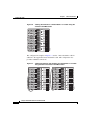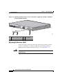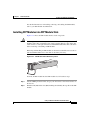
1
You'll be entered into a quarterly drawing for free Cisco Press books by returning this survey! Cisco is dedicated to customer
satisfaction and would like to hear your thoughts on these printed manuals. Please visit the Cisco Product Comments on-line survey at
www.cisco.com/go/crc to submit your comments about accessing Cisco technical manuals. Thank you for your time.
General Information
1
Years of networking experience:
2
I have these network types:
Years of experience with Cisco products:
LAN
Backbone
Switches
Routers
WAN
Other:
3
I have these Cisco products:
4
I perform these types of tasks:
Other (specify models):
Network management
5
I use these types of documentation:
Command reference
H/W installation and/or maintenance
S/W configuration
Other:
H/W installation
H/W configuration
S/W configuration
Quick reference
Release notes
Online help
% Cisco.com
% CD-ROM
% Printed manuals
Cisco.com
CD-ROM
Printed manuals
Other:
6
I access this information through:
% Other:
7
I prefer this access method:
Other:
8
I use the following three product features the most:
Document Information
Document Title:
Catalyst 3750 Switch Hardware Installation Guide
Part Number:
78-15136-02
S/W Release (if applicable):
<Software Release>
On a scale of 1–5 (5 being the best), please let us know how we rate in the following areas:
The document is complete.
The information is accurate.
The information is well organized.
The information I wanted was easy to find.
The document is written at my
technical level of understanding.
The information I found was useful to my job.
Please comment on our lowest scores:
Mailing Information
Organization
Date
Contact Name
Mailing Address
City
State/Province
Zip/Postal Code
Country
Phone (
)
Extension
E-mail
Fax
)
May we contact you further concerning our documentation?
(
Yes
No
You can also send us your comments by e-mail to [email protected], or by fax to 408-527-8089.
When mailing this card from outside of the United States, please enclose in an envelope addressed to the location on the back of this card with
the required postage or fax to 1-408-527-8089.
FIRST-CLASS MAIL
PERMIT NO. 4631
SAN JOSE CA
BUSINESS REPLY MAIL
POSTAGE WILL BE PAID BY ADDRESSEE
DOCUMENT RESOURCE CONNECTION
CISCO SYSTEMS INC
170 WEST TASMAN DR
SAN JOSE CA 95134-9916
NO POSTAGE
NECESSARY
IF MAILED
IN THE
UNITED STATES
Catalyst 3750 Switch
Hardware Installation Guide
August 2003
Corporate Headquarters
Cisco Systems, Inc.
170 West Tasman Drive
San Jose, CA 95134-1706
USA
http://www.cisco.com
Tel: 408 526-4000
800 553-NETS (6387)
Fax: 408 526-4100
Customer Order Number: DOC-7815136=
Text Part Number: 78-15136-02
THE SPECIFICATIONS AND INFORMATION REGARDING THE PRODUCTS IN THIS MANUAL ARE SUBJECT TO CHANGE WITHOUT
NOTICE. ALL STATEMENTS, INFORMATION, AND RECOMMENDATIONS IN THIS MANUAL ARE BELIEVED TO BE ACCURATE BUT
ARE PRESENTED WITHOUT WARRANTY OF ANY KIND, EXPRESS OR IMPLIED. USERS MUST TAKE FULL RESPONSIBILITY FOR
THEIR APPLICATION OF ANY PRODUCTS.
THE SOFTWARE LICENSE AND LIMITED WARRANTY FOR THE ACCOMPANYING PRODUCT ARE SET FORTH IN THE INFORMATION
PACKET THAT SHIPPED WITH THE PRODUCT AND ARE INCORPORATED HEREIN BY THIS REFERENCE. IF YOU ARE UNABLE TO
LOCATE THE SOFTWARE LICENSE OR LIMITED WARRANTY, CONTACT YOUR CISCO REPRESENTATIVE FOR A COPY.
The following information is for FCC compliance of Class A devices: This equipment has been tested and found to comply with the limits for a Class
A digital device, pursuant to part 15 of the FCC rules. These limits are designed to provide reasonable protection against harmful interference when
the equipment is operated in a commercial environment. This equipment generates, uses, and can radiate radio-frequency energy and, if not installed
and used in accordance with the instruction manual, may cause harmful interference to radio communications. Operation of this equipment in a
residential area is likely to cause harmful interference, in which case users will be required to correct the interference at their own expense.
The following information is for FCC compliance of Class B devices: The equipment described in this manual generates and may radiate
radio-frequency energy. If it is not installed in accordance with Cisco’s installation instructions, it may cause interference with radio and television
reception. This equipment has been tested and found to comply with the limits for a Class B digital device in accordance with the specifications in
part 15 of the FCC rules. These specifications are designed to provide reasonable protection against such interference in a residential installation.
However, there is no guarantee that interference will not occur in a particular installation.
Modifying the equipment without Cisco’s written authorization may result in the equipment no longer complying with FCC requirements for Class
A or Class B digital devices. In that event, your right to use the equipment may be limited by FCC regulations, and you may be required to correct
any interference to radio or television communications at your own expense.
You can determine whether your equipment is causing interference by turning it off. If the interference stops, it was probably caused by the Cisco
equipment or one of its peripheral devices. If the equipment causes interference to radio or television reception, try to correct the interference by
using one or more of the following measures:
• Turn the television or radio antenna until the interference stops.
• Move the equipment to one side or the other of the television or radio.
• Move the equipment farther away from the television or radio.
• Plug the equipment into an outlet that is on a different circuit from the television or radio. (That is, make certain the equipment and the television
or radio are on circuits controlled by different circuit breakers or fuses.)
Modifications to this product not authorized by Cisco Systems, Inc. could void the FCC approval and negate your authority to operate the product.
The Cisco implementation of TCP header compression is an adaptation of a program developed by the University of California, Berkeley (UCB) as
part of UCB’s public domain version of the UNIX operating system. All rights reserved. Copyright © 1981, Regents of the University of California.
NOTWITHSTANDING ANY OTHER WARRANTY HEREIN, ALL DOCUMENT FILES AND SOFTWARE OF THESE SUPPLIERS ARE
PROVIDED “AS IS” WITH ALL FAULTS. CISCO AND THE ABOVE-NAMED SUPPLIERS DISCLAIM ALL WARRANTIES, EXPRESSED
OR IMPLIED, INCLUDING, WITHOUT LIMITATION, THOSE OF MERCHANTABILITY, FITNESS FOR A PARTICULAR PURPOSE AND
NONINFRINGEMENT OR ARISING FROM A COURSE OF DEALING, USAGE, OR TRADE PRACTICE.
IN NO EVENT SHALL CISCO OR ITS SUPPLIERS BE LIABLE FOR ANY INDIRECT, SPECIAL, CONSEQUENTIAL, OR INCIDENTAL
DAMAGES, INCLUDING, WITHOUT LIMITATION, LOST PROFITS OR LOSS OR DAMAGE TO DATA ARISING OUT OF THE USE OR
INABILITY TO USE THIS MANUAL, EVEN IF CISCO OR ITS SUPPLIERS HAVE BEEN ADVISED OF THE POSSIBILITY OF SUCH
DAMAGES.
CCIP, CCSP, the Cisco Arrow logo, the Cisco Powered Network mark, Cisco Unity, Follow Me Browsing, FormShare, and StackWise are trademarks of
Cisco Systems, Inc.; Changing the Way We Work, Live, Play, and Learn, and iQuick Study are service marks of Cisco Systems, Inc.; and Aironet, ASIST,
BPX, Catalyst, CCDA, CCDP, CCIE, CCNA, CCNP, Cisco, the Cisco Certified Internetwork Expert logo, Cisco IOS, the Cisco IOS logo, Cisco Press,
Cisco Systems, Cisco Systems Capital, the Cisco Systems logo, Empowering the Internet Generation, Enterprise/Solver, EtherChannel, EtherSwitch,
Fast Step, GigaStack, Internet Quotient, IOS, IP/TV, iQ Expertise, the iQ logo, iQ Net Readiness Scorecard, LightStream, MGX, MICA, the Networkers
logo, Networking Academy, Network Registrar, Packet, PIX, Post-Routing, Pre-Routing, RateMUX, Registrar, ScriptShare, SlideCast, SMARTnet,
StrataView Plus, Stratm, SwitchProbe, TeleRouter, The Fastest Way to Increase Your Internet Quotient, TransPath, and VCO are registered trademarks of
Cisco Systems, Inc. and/or its affiliates in the U.S. and certain other countries.
All other trademarks mentioned in this document or Web site are the property of their respective owners. The use of the word partner does not imply a
partnership relationship between Cisco and any other company. (0304R)
Catalyst 3750 Switch Hardware Installation Guide
Copyright © 2003, Cisco Systems, Inc. All rights reserved.
C O N T E N T S
Cisco Limited Lifetime Hardware Warranty Terms xi
Preface xv
Audience xv
Purpose xv
Conventions xvi
Related Publications xxiii
Obtaining Documentation xxiii
Cisco.com xxiv
Documentation CD-ROM xxiv
Ordering Documentation xxiv
Documentation Feedback xxv
Obtaining Technical Assistance xxv
Cisco.com xxvi
Technical Assistance Center xxvi
Cisco TAC Website xxvii
Cisco TAC Escalation Center xxvii
Obtaining Additional Publications and Information xxviii
CHAPTER
1
Using Express Setup 1-1
Taking Out What You Need 1-2
Powering On the Switch 1-3
Starting Express Setup 1-4
Configuring the Switch Settings 1-9
Verifying Switch IP Address (Optional) 1-10
Catalyst 3750 Switch Hardware Installation Guide
78-15136-02
v
Contents
Rerunning Express Setup 1-11
Where to Go Next 1-12
Other Switch Home Page Features 1-12
Installing or Connecting Devices to the Switch 1-12
CHAPTER
2
Product Overview 2-1
Features 2-1
Front Panel Description 2-3
10/100 and 10/100/1000 Ports 2-6
SFP Module Slots 2-7
SFP Modules 2-7
LEDs 2-8
System LED 2-9
RPS LED 2-9
Master LED 2-10
Port LEDs and Modes 2-10
Rear Panel Description 2-14
StackWise Ports 2-15
Power Connectors 2-16
Internal Power Supply Connector 2-16
Cisco RPS Connector 2-16
Console Port 2-17
Management Options 2-18
Network Configurations 2-19
CHAPTER
3
Switch Installation 3-1
Preparing for Installation 3-1
Warnings 3-2
EMC Regulatory Statements 3-4
Catalyst 3750 Switch Hardware Installation Guide
vi
78-15136-02
Contents
U.S.A. 3-4
Taiwan 3-4
Japan 3-4
Korea 3-5
Hungary 3-5
Installation Guidelines 3-6
Verifying Package Contents 3-7
Verifying Switch Operation 3-8
Connecting a PC or Terminal to the Console Port 3-8
Powering On the Switch and Running POST 3-10
Powering Off the Switch and Disconnecting the Console Port 3-11
Planning the Stack 3-12
Planning Considerations 3-12
Powering Considerations 3-13
Cabling Considerations 3-14
Recommended Cabling Configurations 3-15
Installing the Switch 3-17
Rack Mounting 3-18
Removing Screws from the Switch 3-19
Attaching Brackets to the Catalyst 3750G-24TS Switch 3-20
Attaching Brackets to the Catalyst 3750-24TS, 3750G-24T, 3750G-12S,
and 3750-48TS Switches 3-25
Mounting the Switch in a Rack 3-28
Attaching the Cable Guide 3-30
Wall Mounting 3-32
Attaching the Brackets to the Switch for Wall-Mounting 3-32
Attaching the RPS Connector Cover 3-33
Mounting the Switch on a Wall 3-34
Table or Shelf Mounting 3-36
Connecting StackWise Cable to StackWise Ports 3-37
Catalyst 3750 Switch Hardware Installation Guide
78-15136-02
vii
Contents
Installing and Removing SFP Modules 3-40
Installing SFP Modules into SFP Module Slots 3-41
Removing SFP Modules from SFP Module Slots 3-43
Connecting to the 10/100 and 10/100/1000 Ports 3-44
Connecting to an SFP Module 3-46
Connecting to a Fiber-Optic SFP Module 3-47
Connecting to 1000BASE-T SFP Modules 3-48
Where to Go Next 3-50
CHAPTER
Troubleshooting 4-1
4
Understanding POST Results 4-1
Clearing the Switch IP Address and Configuration 4-2
Diagnosing Problems 4-3
Replacing a Failed Stack Member 4-7
APPENDIX
A
Technical Specifications A-1
APPENDIX
B
Connector and Cable Specifications B-1
Connector Specifications B-1
10/100/1000 Ports B-1
Connecting to 10BASE-T- and 100BASE-TX-Compatible Devices B-2
Connecting to 1000BASE-T Devices B-2
10/100 Ports B-3
SFP Module Ports B-5
Console Port B-6
Cable and Adapter Specifications B-6
Two Twisted-Pair Cable Pinouts B-6
Four Twisted-Pair Cable Pinouts for 10/100 Ports B-7
Four Twisted-Pair Cable Pinouts for 1000BASE-T Ports B-8
Catalyst 3750 Switch Hardware Installation Guide
viii
78-15136-02
Contents
Crossover Cable and Adapter Pinouts B-9
Identifying a Crossover Cable B-9
Adapter Pinouts B-10
APPENDIX
C
Managing the Switch by Using the Cluster Management Suite C-1
Connecting to an Ethernet Port C-2
Launching the Switch Home Page C-3
CMS Requirements C-5
Recommended Configuration for Web-Based Management C-6
Operating System and Browser Support C-6
Supported Java Plug-Ins C-7
Java Plug-In Notes C-8
Where to Go Next C-8
APPENDIX
D
Quick Setup By Using the CLI-Based Setup Program D-1
Methods for Accessing the CLI D-2
Accessing the CLI Through Express Setup (Unconfigured Switch Only) D-2
Accessing the CLI Through the Console Port D-3
Taking Out What You Need D-4
Stacking the Switches (Optional) D-5
Connecting to the Console Port D-7
Starting the Terminal Emulation Software D-9
Connecting to a Power Source D-9
Entering the Initial Configuration Information D-10
IP Settings D-10
Completing the Setup Program D-11
Catalyst 3750 Switch Hardware Installation Guide
78-15136-02
ix
Contents
APPENDIX
E
Translated Safety Warnings E-1
Attaching the Cisco RPS (model PWR300-AC-RPS-N1) E-1
Attaching the Cisco RPS (model PWR675-AC-RPS-N1) E-2
Installation Warning E-4
Installation Instructions E-5
Jewelry Removal Warning E-6
Stacking the Chassis Warning E-8
Main Disconnecting Device E-10
Grounded Equipment Warning E-11
Installing or Replacing the Unit E-12
Overtemperature Warning E-14
Working During Lightning Activity E-16
Product Disposal Warning E-17
Chassis Warning for Rack-Mounting and Servicing E-19
Redundant Power Supply Connection Warning E-24
Switch Installation Warning E-25
Restricted Area E-27
Ethernet Cable Shielding in Offices E-28
Laser Beam Exposure E-30
Laser Radiation E-31
E-32
INDEX
Catalyst 3750 Switch Hardware Installation Guide
x
78-15136-02
Cisco Limited Lifetime Hardware
Warranty Terms
There are special terms applicable to your hardware warranty and various services
that you can use during the warranty period. Follow these steps to access and
download the Cisco Information Packet and your warranty document from
Cisco.com.
1.
Launch your browser, and go to this URL:
http://www.cisco.com/univercd/cc/td/doc/es_inpck/cetrans.htm
The Warranties and License Agreements page appears.
2.
To read the Cisco Information Packet, follow these steps:
a. Click the Information Packet Number field, and make sure that the part
number 78-5235-02F0 is highlighted.
b. Select the language in which you would like to read the document.
c. Click Go.
The Cisco Limited Warranty and Software License page from the
Information Packet appears.
d. Read the document online, or click the PDF icon to download and print
the document in Adobe Portable Document Format (PDF).
Note
You must have Adobe Acrobat Reader to view and print PDF
files. You can download the reader from Adobe’s website:
http://www.adobe.com
Catalyst 3750 Switch Hardware Installation Guide
78-15136-02
xi
Cisco Limited Lifetime Hardware Warranty Terms
3.
To read translated and localized warranty information about your product,
follow these steps:
a. Enter this part number in the Warranty Document Number field:
78-6310-02C0
b. Select the language in which you would like to view the document.
c. Click Go.
The Cisco warranty page appears.
d. Read the document online, or click the PDF icon to download and print
the document in Adobe Portable Document Format (PDF).
You can also contact the Cisco service and support website for assistance:
http://www.cisco.com/public/Support_root.shtml.
Duration of Hardware Warranty
A Cisco product hardware warranty is supported for as long as the original end
user continues to own or use the product, provided that the fan and power supply
warranty is limited to five (5) years. In the event of a discontinuance of product
manufacture, the Cisco warranty support is limited to five (5) years from the
announcement of the discontinuance.
Replacement, Repair, or Refund Policy for Hardware
Cisco or its service center will use commercially reasonable efforts to ship a
replacement part within ten (10) working days after receipt of the Return
Materials Authorization (RMA) request. Actual delivery times can vary,
depending on the customer location.
Cisco reserves the right to refund the purchase price as its exclusive warranty
remedy.
Catalyst 3750 Switch Hardware Installation Guide
xii
78-15136-02
Cisco Limited Lifetime Hardware Warranty Terms
To Receive a Return Materials Authorization (RMA) Number
Contact the company from whom you purchased the product. If you purchased the
product directly from Cisco, contact your Cisco Sales and Service Representative.
Complete the information below, and keep it for reference.
Company product purchased from
Company telephone number
Product model number
Product serial number
Maintenance contract number
Catalyst 3750 Switch Hardware Installation Guide
78-15136-02
xiii
Cisco Limited Lifetime Hardware Warranty Terms
Catalyst 3750 Switch Hardware Installation Guide
xiv
78-15136-02
Preface
Audience
This guide is for the networking or computer technician responsible for installing
the Catalyst 3750 switches. We assume that you are familiar with the concepts
and terminology of Ethernet and local area networking.
Purpose
This guide documents the hardware features of the Catalyst 3750 family of
switches. It describes the physical and performance characteristics of each switch,
explains how to install a switch, and provides troubleshooting information.
This guide does not describe system messages that you might receive or how to
configure your switch. For more information, refer to the switch software
configuration guide, the switch command reference, and the switch system
message guide on the Cisco.com Product Documentation home page. For
information about the standard Cisco IOS Release 12.1 commands, refer to the
IOS documentation set from the Cisco.com home page at Service and Support >
Technical Documents. On the Cisco Product Documentation home page, select
Release 12.1 from the Cisco IOS Software drop-down list.
Catalyst 3750 Switch Hardware Installation Guide
78-15136-02
xv
Preface
Conventions
Conventions
This document uses these conventions and symbols for notes, cautions, and
warnings:
Note
Caution
Warning
Means reader take note. Notes contain helpful suggestions or references to
materials not contained in this manual.
Means reader be careful. In this situation, you might do something that could
result in equipment damage or loss of data.
IMPORTANT SAFETY INSTRUCTIONS
This warning symbol means danger. You are in a situation that could cause
bodily injury. Before you work on any equipment, be aware of the hazards
involved with electrical circuitry and be familiar with standard practices for
preventing accidents. Use the statement number provided at the end of each
warning to locate its translation in the translated safety warnings that
accompanied this device.
SAVE THESE INSTRUCTIONS
Waarschuwing
BELANGRIJKE VEILIGHEIDSINSTRUCTIES
Dit waarschuwingssymbool betekent gevaar. U verkeert in een situatie die
lichamelijk letsel kan veroorzaken. Voordat u aan enige apparatuur gaat
werken, dient u zich bewust te zijn van de bij elektrische schakelingen
betrokken risico's en dient u op de hoogte te zijn van de standaard praktijken
om ongelukken te voorkomen. Gebruik het nummer van de verklaring
onderaan de waarschuwing als u een vertaling van de waarschuwing die bij
het apparaat wordt geleverd, wilt raadplegen.
BEWAAR DEZE INSTRUCTIES
Catalyst 3750 Switch Hardware Installation Guide
xvi
78-15136-02
Preface
Conventions
Varoitus
TÄRKEITÄ TURVALLISUUSOHJEITA
Tämä varoitusmerkki merkitsee vaaraa. Tilanne voi aiheuttaa ruumiillisia
vammoja. Ennen kuin käsittelet laitteistoa, huomioi sähköpiirien
käsittelemiseen liittyvät riskit ja tutustu onnettomuuksien yleisiin
ehkäisytapoihin. Turvallisuusvaroitusten käännökset löytyvät laitteen
mukana toimitettujen käännettyjen turvallisuusvaroitusten joukosta
varoitusten lopussa näkyvien lausuntonumeroiden avulla.
SÄILYTÄ NÄMÄ OHJEET
Attention
IMPORTANTES INFORMATIONS DE SÉCURITÉ
Ce symbole d'avertissement indique un danger. Vous vous trouvez dans une
situation pouvant entraîner des blessures ou des dommages corporels. Avant
de travailler sur un équipement, soyez conscient des dangers liés aux circuits
électriques et familiarisez-vous avec les procédures couramment utilisées
pour éviter les accidents. Pour prendre connaissance des traductions des
avertissements figurant dans les consignes de sécurité traduites qui
accompagnent cet appareil, référez-vous au numéro de l'instruction situé à la
fin de chaque avertissement.
CONSERVEZ CES INFORMATIONS
Warnung
WICHTIGE SICHERHEITSHINWEISE
Dieses Warnsymbol bedeutet Gefahr. Sie befinden sich in einer Situation, die
zu Verletzungen führen kann. Machen Sie sich vor der Arbeit mit Geräten mit
den Gefahren elektrischer Schaltungen und den üblichen Verfahren zur
Vorbeugung vor Unfällen vertraut. Suchen Sie mit der am Ende jeder Warnung
angegebenen Anweisungsnummer nach der jeweiligen Übersetzung in den
übersetzten Sicherheitshinweisen, die zusammen mit diesem Gerät
ausgeliefert wurden.
BEWAHREN SIE DIESE HINWEISE GUT AUF.
Catalyst 3750 Switch Hardware Installation Guide
78-15136-02
xvii
Preface
Conventions
Avvertenza
IMPORTANTI ISTRUZIONI SULLA SICUREZZA
Questo simbolo di avvertenza indica un pericolo. La situazione potrebbe
causare infortuni alle persone. Prima di intervenire su qualsiasi
apparecchiatura, occorre essere al corrente dei pericoli relativi ai circuiti
elettrici e conoscere le procedure standard per la prevenzione di incidenti.
Utilizzare il numero di istruzione presente alla fine di ciascuna avvertenza per
individuare le traduzioni delle avvertenze riportate in questo documento.
CONSERVARE QUESTE ISTRUZIONI
Advarsel
VIKTIGE SIKKERHETSINSTRUKSJONER
Dette advarselssymbolet betyr fare. Du er i en situasjon som kan føre til skade
på person. Før du begynner å arbeide med noe av utstyret, må du være
oppmerksom på farene forbundet med elektriske kretser, og kjenne til
standardprosedyrer for å forhindre ulykker. Bruk nummeret i slutten av hver
advarsel for å finne oversettelsen i de oversatte sikkerhetsadvarslene som
fulgte med denne enheten.
TA VARE PÅ DISSE INSTRUKSJONENE
Aviso
INSTRUÇÕES IMPORTANTES DE SEGURANÇA
Este símbolo de aviso significa perigo. Você está em uma situação que poderá
ser causadora de lesões corporais. Antes de iniciar a utilização de qualquer
equipamento, tenha conhecimento dos perigos envolvidos no manuseio de
circuitos elétricos e familiarize-se com as práticas habituais de prevenção de
acidentes. Utilize o número da instrução fornecido ao final de cada aviso para
localizar sua tradução nos avisos de segurança traduzidos que acompanham
este dispositivo.
GUARDE ESTAS INSTRUÇÕES
Catalyst 3750 Switch Hardware Installation Guide
xviii
78-15136-02
Preface
Conventions
¡Advertencia!
INSTRUCCIONES IMPORTANTES DE SEGURIDAD
Este símbolo de aviso indica peligro. Existe riesgo para su integridad física.
Antes de manipular cualquier equipo, considere los riesgos de la corriente
eléctrica y familiarícese con los procedimientos estándar de prevención de
accidentes. Al final de cada advertencia encontrará el número que le ayudará
a encontrar el texto traducido en el apartado de traducciones que acompaña
a este dispositivo.
GUARDE ESTAS INSTRUCCIONES
Varning!
VIKTIGA SÄKERHETSANVISNINGAR
Denna varningssignal signalerar fara. Du befinner dig i en situation som kan
leda till personskada. Innan du utför arbete på någon utrustning måste du vara
medveten om farorna med elkretsar och känna till vanliga förfaranden för att
förebygga olyckor. Använd det nummer som finns i slutet av varje varning för
att hitta dess översättning i de översatta säkerhetsvarningar som medföljer
denna anordning.
SPARA DESSA ANVISNINGAR
Catalyst 3750 Switch Hardware Installation Guide
78-15136-02
xix
Preface
Conventions
Catalyst 3750 Switch Hardware Installation Guide
xx
78-15136-02
Preface
Related Publications
Related Publications
You can order printed copies of documents with a DOC-xxxxxx= number. For
more information, see the “Ordering Documentation” section on page xxii.
These documents provide complete information about the switch and are
available from this Cisco.com site:
http://www.cisco.com/univercd/cc/td/doc/product/lan/cat3750/index.htm
•
Note
Release Notes for the Catalyst 3750 Switch (not orderable but available on
Cisco.com)
Before installing, configuring, or upgrading the switch, refer to the release notes
on Cisco.com for the latest information.
•
Catalyst 3750 Switch Software Configuration Guide (order number
DOC-7815164=)
•
Catalyst 3750 Switch Command Reference (order number DOC-7815165=)
•
Catalyst 3750 Switch System Message Guide (order number DOC-7815166=)
•
Cluster Management Suite (CMS) online help (available only from the switch
CMS software)
•
Catalyst 3750 Switch Hardware Installation Guide (order number
DOC-7815136=)
•
Cisco Small Form-Factor Pluggable Modules Installation Notes (order
number DOC-7815160=)
•
Cisco Small Form-Factor Pluggable Modules Compatibility Matrix (not
orderable but available on Cisco.com)
•
Compatibility Matrix for 1000BASE-T Small Form-Factor Pluggable
Modules (not orderable but available on Cisco.com)
Obtaining Documentation
Cisco provides several ways to obtain documentation, technical assistance, and
other technical resources. These sections explain how to obtain technical
information from Cisco Systems.
Catalyst 3750 Switch Hardware Installation Guide
78-15136-02
xxi
Preface
Obtaining Documentation
Cisco.com
You can access the most current Cisco documentation on the World Wide Web at
this URL:
http://www.cisco.com/univercd/home/home.htm
You can access the Cisco website at this URL:
http://www.cisco.com
International Cisco websites can be accessed from this URL:
http://www.cisco.com/public/countries_languages.shtml
Documentation CD-ROM
Cisco documentation and additional literature are available in a Cisco
Documentation CD-ROM package, which may have shipped with your product.
The Documentation CD-ROM is updated regularly and may be more current than
printed documentation. The CD-ROM package is available as a single unit or
through an annual or quarterly subscription.
Registered Cisco.com users can order a single Documentation CD-ROM (product
number DOC-CONDOCCD=) through the Cisco Ordering tool:
http://www.cisco.com/en/US/partner/ordering/ordering_place_order_ordering_t
ool_launch.html
All users can order annual or quarterly subscriptions through the online
Subscription Store:
http://www.cisco.com/go/subscription
Ordering Documentation
You can find instructions for ordering documentation at this URL:
http://www.cisco.com/univercd/cc/td/doc/es_inpck/pdi.htm
You can order Cisco documentation in these ways:
•
Registered Cisco.com users (Cisco direct customers) can order Cisco product
documentation from the Networking Products MarketPlace:
Catalyst 3750 Switch Hardware Installation Guide
xxii
78-15136-02
Preface
Obtaining Technical Assistance
http://www.cisco.com/en/US/partner/ordering/index.shtml
•
Nonregistered Cisco.com users can order documentation through a local
account representative by calling Cisco Systems Corporate Headquarters
(California, USA.) at 408 526-7208 or, elsewhere in North America, by
calling 800 553-NETS (6387).
Documentation Feedback
You can submit comments electronically on Cisco.com. On the Cisco
Documentation home page, click Feedback at the top of the page.
You can send your comments in e-mail to [email protected].
You can submit comments by using the response card (if present) behind the front
cover of your document or by writing to the following address:
Cisco Systems
Attn: Customer Document Ordering
170 West Tasman Drive
San Jose, CA 95134-9883
We appreciate your comments.
Obtaining Technical Assistance
For all customers, partners, resellers, and distributors who hold valid Cisco
service contracts, the Cisco Technical Assistance Center (TAC) provides 24-hour,
award-winning technical support services, online and over the phone. Cisco.com
features the Cisco TAC website as an online starting point for technical
assistance.
Cisco TAC Website
The Cisco TAC website (http://www.cisco.com/tac) provides online documents
and tools for troubleshooting and resolving technical issues with Cisco products
and technologies. The Cisco TAC website is available 24 hours a day, 365 days a
year.
Catalyst 3750 Switch Hardware Installation Guide
78-15136-02
xxiii
Preface
Obtaining Technical Assistance
Accessing all the tools on the Cisco TAC website requires a Cisco.com user ID
and password. If you have a valid service contract but do not have a login ID or
password, register at this URL:
http://tools.cisco.com/RPF/register/register.do
Opening a TAC Case
The online TAC Case Open Tool (http://www.cisco.com/tac/caseopen) is the
fastest way to open P3 and P4 cases. (Your network is minimally impaired or you
require product information). After you describe your situation, the TAC Case
Open Tool automatically recommends resources for an immediate solution. If
your issue is not resolved using these recommendations, your case will be
assigned to a Cisco TAC engineer.
For P1 or P2 cases (your production network is down or severely degraded) or if
you do not have Internet access, contact Cisco TAC by telephone. Cisco TAC
engineers are assigned immediately to P1 and P2 cases to help keep your business
operations running smoothly.
To open a case by telephone, use one of the following numbers:
Asia-Pacific: +61 2 8446 7411 (Australia: 1 800 805 227)
EMEA: +32 2 704 55 55
USA: 1 800 553-2447
For a complete listing of Cisco TAC contacts, go to this URL:
http://www.cisco.com/warp/public/687/Directory/DirTAC.shtml
TAC Case Priority Definitions
To ensure that all cases are reported in a standard format, Cisco has established
case priority definitions.
Priority 1 (P1)—Your network is “down” or there is a critical impact to your
business operations. You and Cisco will commit all necessary resources around
the clock to resolve the situation.
Catalyst 3750 Switch Hardware Installation Guide
xxiv
78-15136-02
Preface
Obtaining Additional Publications and Information
Priority 2 (P2)—Operation of an existing network is severely degraded, or
significant aspects of your business operation are negatively affected by
inadequate performance of Cisco products. You and Cisco will commit full-time
resources during normal business hours to resolve the situation.
Priority 3 (P3)—Operational performance of your network is impaired, but most
business operations remain functional. You and Cisco will commit resources
during normal business hours to restore service to satisfactory levels.
Priority 4 (P4)—You require information or assistance with Cisco product
capabilities, installation, or configuration. There is little or no effect on your
business operations.
Obtaining Additional Publications and Information
Information about Cisco products, technologies, and network solutions is
available from various online and printed sources.
•
The Cisco Product Catalog describes the networking products offered by
Cisco Systems, as well as ordering and customer support services. Access the
Cisco Product Catalog at this URL:
http://www.cisco.com/en/US/products/products_catalog_links_launch.html
•
Cisco Press publishes a wide range of networking publications. Cisco
suggests these titles for new and experienced users: Internetworking Terms
and Acronyms Dictionary, Internetworking Technology Handbook,
Internetworking Troubleshooting Guide, and the Internetworking Design
Guide. For current Cisco Press titles and other information, go to Cisco Press
online at this URL:
http://www.ciscopress.com
•
Packet magazine is the Cisco quarterly publication that provides the latest
networking trends, technology breakthroughs, and Cisco products and
solutions to help industry professionals get the most from their networking
investment. Included are networking deployment and troubleshooting tips,
configuration examples, customer case studies, tutorials and training,
certification information, and links to numerous in-depth online resources.
You can access Packet magazine at this URL:
http://www.cisco.com/go/packet
Catalyst 3750 Switch Hardware Installation Guide
78-15136-02
xxv
Preface
Obtaining Additional Publications and Information
•
iQ Magazine is the Cisco bimonthly publication that delivers the latest
information about Internet business strategies for executives. You can access
iQ Magazine at this URL:
http://www.cisco.com/go/iqmagazine
•
Internet Protocol Journal is a quarterly journal published by Cisco Systems
for engineering professionals involved in designing, developing, and
operating public and private internets and intranets. You can access the
Internet Protocol Journal at this URL:
http://www.cisco.com/en/US/about/ac123/ac147/about_cisco_the_internet_
protocol_journal.html
•
Training—Cisco offers world-class networking training. Current offerings in
network training are listed at this URL:
http://www.cisco.com/en/US/learning/index.html
Catalyst 3750 Switch Hardware Installation Guide
xxvi
78-15136-02
C H A P T E R
1
Using Express Setup
This chapter provides a quick, step-by-step setup procedure for a standalone
switch or a switch stack.
Note
Express Setup is supported on switches running Cisco IOS Release 12.1(14)EA1
or later. If you are installing a new switch, refer to the Cisco IOS release label on
the rear panel of the switch to determine the release.
For quick setup instructions for switches running releases earlier than Cisco IOS
Release 12.1(14)EA1, go to Appendix D, “Quick Setup By Using the CLI-Based
Setup Program.”
The setup procedure includes these steps:
•
Taking Out What You Need, page 1-2
•
Powering On the Switch, page 1-3
•
Starting Express Setup, page 1-4
•
Configuring the Switch Settings, page 1-9
•
Where to Go Next, page 1-12
Catalyst 3750 Switch Hardware Installation Guide
78-15136-02
1-1
Chapter 1
Using Express Setup
Taking Out What You Need
Caution
Do not start Express Setup when there are any devices connected to the switch or
connect a switch that is already in Express Setup mode to any device other than
the PC or workstation that is being used to configure it. The switch acts as a DHCP
server during the Express Setup procedure, and only the PC or workstation
connected to the switch after Express Startup is started should receive a DHCP
address from the switch.
Taking Out What You Need
Remove the items shown in Figure 1-1 from the shipping container.
Figure 1-1
1
Catalyst 3750 Switch and AC Power Cord
SYST
RPS
MASTR
STAT
DUPLX
SPEED
STACK
1X
MODE
11X
13X
2X
23X
12X
Catalyst
3750 SERIES
14X
97175
24X
2
1
Switch
2
AC power cord
You also need to provide an Ethernet (Category 5) straight-through cable (not
included), as shown in Figure 1-2, to connect the switch to your PC or
workstation.
Catalyst 3750 Switch Hardware Installation Guide
1-2
78-15136-02
Chapter 1
Using Express Setup
Powering On the Switch
Ethernet Cable
89887
Figure 1-2
Powering On the Switch
Complete these steps to power on the switch:
Step 1
Connect one end of the AC power cord to the power connector on the switch rear
panel, as shown in Figure 1-3.
Figure 1-3
Connecting the Power
1
STACK
1
STACK
2
CONSO
LE
0 HZ
TS FOR
REMOTE
POWER
SUPPLY
SPECIFI
ED IN
MANUAL
+12v
@13A
97176
DC INPU
RATING
100-240V
~
1.2A-0>6
A, 50-6
2
1
Switch
2
AC power cord
Catalyst 3750 Switch Hardware Installation Guide
78-15136-02
1-3
Chapter 1
Using Express Setup
Starting Express Setup
Step 2
Connect the other end of the power cable to a grounded AC outlet.
After the switch powers on, it begins the power-on self-test (POST), a series of
tests that run automatically to ensure that the switch functions properly.
POST lasts approximately 1 minute. When POST is complete, only the SYST and
STAT LEDs remain green. The MASTR LED is also green on a single switch or
on a stack master switch.
The SYST LED turns amber if the POST fails. If the POST fails, see Chapter 4,
“Troubleshooting,” to determine a course of action.
Starting Express Setup
Express Setup is a browser-based program that you can use to set up and configure
the switch. You assign the IP information so that the switch can connect to local
routers and the Internet. The IP address is also required if you plan to further
configure the switch.
You do not create a username with Express Setup. Express Setup provides the
mimimum configuration to configure a switch. To create a username for the
switch, use the Cluster Managment Suite (CMS) or the command-line interface
(CLI).
Note
Before starting Express Setup, verify that the switch has passed POST and that the
SYST and STAT LEDs are green. For information about troubleshooting a POST
failure, see the “Understanding POST Results” section on page 4-2. You cannot
start Express Setup until POST has completed.
Caution
Do not start Express Setup when there are any devices connected to the switch.
The switch acts as a DHCP server during the Express Setup procedure, and only
the PC or workstation connected to the switch after Express Startup is started
should receive a DHCP address from the switch.
Catalyst 3750 Switch Hardware Installation Guide
1-4
78-15136-02
Chapter 1
Using Express Setup
Starting Express Setup
Follow these steps to start the Express Setup program:
Step 1
Verify that no devices are connected to the switch.
Step 2
Press and hold the Mode button, as shown in Figure 1-4, until the four LEDs
above the Mode button turn green. This takes approximately 3 seconds.
Figure 1-4
Starting Express Setup
SYST
RPS
MASTR
STAT
DUPLX
SPEED
STACK
97173
MODE
1
1 Mode button
Step 3
Note
Step 4
Release the Mode button.
If all of the LEDs begin to blink after you press the Mode button, release it.
Blinking LEDs mean that the switch has already been configured and cannot go
into Express Setup mode. For more information, see the “Clearing the Switch IP
Address and Configuration” section on page 4-2.
Connect the Ethernet cable (not included) to a 10/100 Ethernet port or small
form-factor pluggable (SFP) module port on the front panel of the switch, as
shown in Figure 1-5.
Catalyst 3750 Switch Hardware Installation Guide
78-15136-02
1-5
Chapter 1
Using Express Setup
Starting Express Setup
Caution
Do not connect the switch to any device other than the PC or workstation being
used to configure it.
Figure 1-5
Connecting the Switch and PC or Workstation Ethernet Ports
1
SYST
RPS
MASTR
STAT
DUPLX
SPEED
STACK
1X
MODE
11X
13X
2X
23X
12X
Catalyst
3750 SERIES
14X
24X
3
1 Switch
97174
2
3 PC or workstation
2 Ethernet cable
Step 5
Connect the other end of the cable to the Ethernet port on the PC or workstation.
Verify that the port status LEDs on both connected Ethernet ports are green.
Step 6
Wait approximately 30 seconds after the port LEDs turn green, and launch a web
browser on your PC or workstation.
Step 7
Enter the IP address 10.0.0.1, as shown in Figure 1-6, and press Enter.
Catalyst 3750 Switch Hardware Installation Guide
1-6
78-15136-02
Chapter 1
Using Express Setup
Starting Express Setup
Figure 1-6
Entering the IP Address
The Express Setup home page appears, as shown in Figure 1-7.
Figure 1-7
Express Setup Home Page
If the Express Setup does not run, or the Express Setup home page does not appear
in your browser:
•
Did you wait 30 seconds after connecting the switch and PC or workstation
before entering the IP address in your browser?
If not, wait 30 seconds, and re-enter 10.0.0.1 in the browser, and press Enter.
•
Did you enter the wrong address in the browser, or is there an error message
displayed in the browser window?
Catalyst 3750 Switch Hardware Installation Guide
78-15136-02
1-7
Chapter 1
Using Express Setup
Starting Express Setup
Re-enter 10.0.0.1 in the browser, and press Enter.
•
Did you connect a crossover instead of a straight-through Ethernet cable
between an Ethernet port of the switch and the Ethernet port of the PC or
workstation, as shown Figure 1-5.
Note
See Figure B-11 on page B-9 for instructions on identifying a crossover
cable.
Note
On switches running Cisco IOS Release 12.1(14)EA1 or later, you can
use the mdix auto command in the CLI to enable the automatic crossover
feature. When the automatic crossover feature is enabled, the switch
detects the required cable type for copper Ethernet connections and
configures the interfaces accordingly. Therefore, you can use either a
crossover or a straight-through cable for connections to a copper 10/100
or 10/100/1000 port on the switch, regardless the type of device on the
other end of the connection.
The automatic crossover feature is disabled by default. For configuration
information for this feature, refer to the switch software configuration
guide or the switch command reference.
If not, reconnect the cable to the Ethernet port on the switch and PC or
workstation. Wait 30 seconds before entering 10.0.0.1 in the browser.
•
Did you verify that POST successfully ran before starting Express Setup?
If not, make sure that only the SYST and STAT LEDs are green before
pressing the Mode button to begin Express Setup.
Note
The rest of this chapter explains how to configure a switch by using the Express
Setup web page. To configure the switch by using the command-line interface
(CLI)-based setup program, see Appendix D, “Quick Setup By Using the
CLI-Based Setup Program.”
Catalyst 3750 Switch Hardware Installation Guide
1-8
78-15136-02
Chapter 1
Using Express Setup
Configuring the Switch Settings
Configuring the Switch Settings
The Management Interface field displays VLAN1-Default. This is the
management interface through which you manage the switch and to which you
assign IP information.
Follow these steps to configure your switch with Express Setup:
Step 1
Contact your system administrator and obtain the IP address, the IP subnet mask,
and the default gateway for your switch.
Step 2
Enter the IP address of the switch in the IP Address field.
Step 3
Click the drop-down arrow in the IP Subnet Mask field, and select an IP Subnet
Mask.
Step 4
Enter the IP address for the default gateway in the Default Gateway field.
A gateway (router or dedicated network device) is a system that connects a
network on one subnet to one or more networks on a different subnet.
Note
Step 5
You must specify a default gateway if the management workstation and the switch
are on different IP segments.
Enter your password in the Switch Password field.
The password can be from 1 to 25 alphanumeric characters, can start with a
number, is case sensitive, allows embedded spaces, but does not allow embedded
spaces at the beginning or end.
Step 6
Enter your password again in the Confirm Switch Password field.
You do not enter a username for the switch. After the switch is configured with an
IP address, you can use CMS to configure a username.
Step 7
(Optional) Enter a host name for the switch in the Host Name field. The host
name is limited to 31 characters; embedded spaces are not allowed.
Step 8
(Optional) Enter the name of your system contact in the System Contact field.
This identifies the system administrator for the switch or network.
Step 9
(Optional) Enter your system location in the System Location field. This
identifies the physical location of the switch.
Catalyst 3750 Switch Hardware Installation Guide
78-15136-02
1-9
Chapter 1
Using Express Setup
Verifying Switch IP Address (Optional)
Step 10
Step 11
(Optional) Click Enable in the Telnet Access field if you are going to use Telnet
to manage the switch by using the CLI. If you enable Telnet access, you must enter
a Telnet password:
a.
Enter a password in the Telnet Password field. The Telnet password can be
from 1 to 25 alphanumeric characters, is case sensitive, allows embedded
spaces, but does not allow embedded spaces at the beginning or end.
b.
Enter the Telnet password again in the Confirm Telnet Password field.
(Optional) Click Enable to configure Simple Network Management Protocol
(SNMP). Enable SNMP only if you plan to manage switches by using Cisco
Works or another SNMP-based network-management system.
If you enable SNMP, you must enter a community string in either the SNMP Read
Community field, the SNMP Write Community field, or both. SNMP
community strings authenticate access to MIB objects. Embedded spaces are not
allowed in SNMP community strings. If you set the SNMP read community, users
can access MIB objects, but cannot modify them. If you set the SNMP write
community, users can access and modify MIB objects.
Step 12
Click Save to save your settings to the switch, or click Cancel to clear your
settings.
The switch exits Express Setup mode.
Your switch is now configured with the new IP address. You can install the switch
in your production network.
Verifying Switch IP Address (Optional)
After you have installed the switch in your network, follow these steps to verify
the IP address configured on your switch:
Step 1
Launch a web browser on a PC or workstation that is connected the network.
Step 2
Enter the IP address of your switch (for example: 172.20.139.142.) The switch
home page appears, as shown in Figure 1-8.
Catalyst 3750 Switch Hardware Installation Guide
1-10
78-15136-02
Chapter 1
Using Express Setup
Rerunning Express Setup
Figure 1-8
Switch Home Page
Rerunning Express Setup
If you did not click Save at the end of the Configuring the Switch Settings section,
you can rerun Express Setup by clicking Express Setup on the Switch home page.
If you have entered a wrong IP address or need to change the IP address of your
switch, you can clear the IP address on your switch by following the steps in the
“Clearing the Switch IP Address and Configuration” section on page 4-2.
Catalyst 3750 Switch Hardware Installation Guide
78-15136-02
1-11
Chapter 1
Using Express Setup
Where to Go Next
Where to Go Next
After you have saved your configuration to the switch, you can install the switch
or further configure it by using CMS or the CLI.
Other Switch Home Page Features
These additional features are available from the switch home page, as shown on
the left menu bar in Figure 1-8 on page 1-11:
•
Cluster Management Suite—Launch the CMS, through which you can
configure and monitor a switch or switch clusters, display network topologies
to gather link information, and display switch images to modify switch- and
port-level settings. For more information, refer to the switch software
configuration guide
For CMS requirements, see Appendix C, “Managing the Switch by Using the
Cluster Management Suite.”
•
Tools—Access diagnostic and monitoring tools such as Telnet and Extended
Ping.
•
Help Resources—Access Catalyst 3750 documentation.
Installing or Connecting Devices to the Switch
For detailed installation procedures on mounting your switch on or under a desk
or on a wall, or connecting devices to the switch, see Chapter 3, “Installation.”
Catalyst 3750 Switch Hardware Installation Guide
1-12
78-15136-02
C H A P T E R
2
Product Overview
The Catalyst 3750 family of switches—also referred to as the switches—are
stackable Ethernet switches to which you can connect devices like Cisco IP
Phones, Cisco Wireless Access Points workstations, and other network devices
such as servers, routers, and other switches. This chapter provides a functional
overview of the Catalyst 3750 switch models. These topics are included:
•
Features, page 2-1
•
Front Panel Description, page 2-3
•
Rear Panel Description, page 2-14
•
Management Options, page 2-18
Features
The switches can be deployed as backbone switches, aggregating 10BASE-T,
100BASE-TX, and 1000BASE-T Ethernet traffic from other network devices.
Refer to the switch software configuration guide for examples showing how you
might deploy the switches in your network.
Catalyst 3750 Switch Hardware Installation Guide
78-15136-02
2-1
Chapter 2
Product Overview
Features
Figure 2-1 through Figure 2-5 show the Catalyst 3750 switches.
These are the switch features:
•
Hardware
– Catalyst 3750-24TS—24 10/100 Ethernet ports and 2 small form-factor
pluggable (SFP) module slots
– Catalyst 3750G-24T—24 10/100/1000 Ethernet ports
– Catalyst 3750G-24TS—24 10/100/1000 Ethernet ports and 4 SFP
module slots
– Catalyst 3750-48TS—48 10/100 Ethernet ports and 4 SFP module slots
– Catalyst 3750G-12S—12 SFP module slots
•
The switches support these SFP modules:
– 1000BASE-SX
– 1000BASE-LX
– 1000BASE-T
Note
•
When installed in Catalyst 3750 switches, 1000BASE-T small
form-factor pluggable (SFP) modules can either operate at 10, 100, or
1000 Mbps in full-duplex mode or in half-duplex mode at 10 or 100
Mbps.
Configuration
– For 10/100 ports, autonegotiates the speed and duplex settings
– For 10/100/1000 ports, autonegotiates the speed and supports only
full-duplex mode
•
The Catalyst 3750 switches support stacking. You can stack up to nine
switches in a stack by cabling the StackWise ports. StackWise ports are not
user-configurable.
•
Switches are hot-swappable
•
Power redundancy
– Connection for optional Cisco RPS 300 redundant power system that
operates on AC input and supplies backup DC power output to the
Catalyst 3750-24TS, 3750G-24T, 3750-48TS, and 3750G-12S switches.
Catalyst 3750 Switch Hardware Installation Guide
2-2
78-15136-02
Chapter 2
Product Overview
Front Panel Description
The Cisco RPS 300 does not support the Catalyst 3750G-24TS
switch.
Note
– Connection for optional Cisco RPS 675 redundant power system that
operates on AC input and supplies backup DC power output to the family
of Catalyst 3750 switches.
Front Panel Description
The Catalyst 3750-24TS 10/100 ports are numbered 1 through 24. The ports are
grouped in pairs. The first member of the pair (port 1) is above the second member
(port 2) on the far left, as shown in Figure 2-1. Port 3 is above port 4, and so on.
The SFP port numbers are numbered 1 (left) and 2 (right).
Catalyst 3750-24TS Front Panel
SYST
RPS
MASTR
STAT
DUPLX
SPEED
STACK
1
1X
MODE
2
3
4
5
6
7
8
9
10
11
12
11X
13
13X
14
15
16
17
18
19
20
2X
21
22
23
Catalyst
24
3750 SERIE
86541
Figure 2-1
S
23X
12X
14X
1
24X
2
1
2
1
10/100 ports
2
SFP module ports
The 10/100/1000 ports on the Catalyst 3750G-24T and 3750G-24TS are grouped
in pairs. The first member of the pair (port 1) is above the second member (port 2)
on the left, as shown in Figure 2-2 and Figure 2-3. Port 3 is above port 4, and so
on. In Figure 2-3 the SFP port are numbered 25 to 28.
Catalyst 3750 Switch Hardware Installation Guide
78-15136-02
2-3
Chapter 2
Product Overview
Front Panel Description
SYST
RPS
MASTR
STAT
DUPLX
SPEED
STACK
Catalyst 3750G-24T Front Panel
1
2
3
4
1X
5
6
7
8
9
10
11
86543
Figure 2-2
12
MODE
11X
13
14
15
16
13X
2X
17
18
19
20
21
22
23
24
Catalyst
23X
12X
3750 SERIE
S
14X
24X
1
10/100/1000 ports
Figure 2-3
SYST
RPS
MASTR
STAT
DUPLX
SPEED
STACK
Catalyst 3750G-24TS Front Panel
1
1X
2
3
4
5
6
7
8
9
10
11
12
MODE
11X
13
13X
2X
14
15
16
17
Catalyst
18
19
3750 SERIE
S
20
21
22
23
86544
1
24
23X
12X
25
14X
26
27
28
24X
1
2
1
10/100 ports
2
SFP module ports
The Catalyst 3750G-12S SFP module slots are numbered 1 through 12. The ports
are grouped in three sets of four, as shown in Figure 2-4.
Catalyst 3750 Switch Hardware Installation Guide
2-4
78-15136-02
Chapter 2
Product Overview
Front Panel Description
Figure 2-4
Catalyst 3750G-12S Front Panel
97166
SYST
RPS
MASTR
STAT
DUPLX
SPEED
STACK
MODE
1
2
3
4
5
Catalyst
6
7
3750 SERIE
S
8
9
10
11
12
1
1
SFP module ports
The Catalyst 3750-48TS 10/100 ports are numbered 1 through 48. The ports are
grouped in pairs. The first member of the pair (port 1) is above the second member
(port 2) on the far left, as shown in Figure 2-1. Port 3 is above port 4, and so on.
The SFP port numbers are 1 (top) and 2 (bottom) and so on.
1
SYST
RPS
MASTR
STAT
DUPLX
SPEED
STACK
MODE
1X
2
3
4
5
6
7
Catalyst 3750-48TS Front Panel
8
9
10
11
12
13
14
15
16
17
15X 17X
18
19
20
21
22
23
24
25
2X
26
27
28
29
30
31
86542
Figure 2-5
32
33
31X 33X
16X 18X
34
35
36
37
38
39
40
41
42
43
44
45
46
47
Catalyst
48
3750 SERIE
S
47X
32X 34X
1
3
2
48X
4
1
2
1
10/100 ports
2
SFP module ports
Catalyst 3750 Switch Hardware Installation Guide
78-15136-02
2-5
Chapter 2
Product Overview
Front Panel Description
10/100 and 10/100/1000 Ports
You can set the 10/100 on the switch to operate in any combination of half duplex,
full duplex, 10 Mbps or 100 Mbps. You can set the 10/100/1000 ports to operate
in 10 Mbps, 100 Mbps, or 1000 Mbps in full duplex. You can also set these ports
for speed and duplex autonegotiation in compliance with IEEE 802.3ab. (The
default setting is autonegotiate.) When set for autonegotiation, the port senses the
speed and duplex settings of the attached device and advertises its own
capabilities. If the connected device also supports autonegotiation, the switch port
negotiates the best connection (that is, the fastest line speed that both devices
support and full-duplex transmission if the attached device supports it) and
configures itself accordingly. In all cases, the attached device must be within 328
feet (100 meters).
Note
100BASE-TX and 1000BASE-T traffic requires Category 5 cable. 10BASE-T
traffic can use Category 3 or Category 4 cables.
When connecting the switch to workstations, servers, routers, and Cisco IP
Phones, be sure that the cable is a straight-through cable. When connecting the
switch to switches or hubs, use a crossover cable. When using a straight-through
or crossover cable for 1000BASE-T connections, be sure to use a twisted
four-pair, Category 5 cable for proper operation. Pinouts for the cables are
described in Appendix B, “Connector and Cable Specifications.”
Note
On switches running Cisco IOS Release 12.1(14)EA1 or later, you can use the
mdix auto command in the CLI to enable the automatic crossover feature. When
the automatic crossover feature is enabled, the switch detects the required cable
type for copper Ethernet connections and configures the interfaces accordingly.
Therefore, you can use either a crossover or a straight-through cable for
connections to a copper 10/100 or 10/100/1000 port on the switch, regardless the
type of device on the other end of the connection.
The automatic crossover feature is disabled by default. For configuration
information for this feature, refer to the switch software configuration guide or the
switch command reference.
Catalyst 3750 Switch Hardware Installation Guide
2-6
78-15136-02
Chapter 2
Product Overview
Front Panel Description
SFP Module Slots
The SFP module slots support the SFP modules listed in the Catalyst 3750 release
notes.
SFP Modules
The Catalyst 3750 switch uses Gigabit Ethernet SFP modules to establish
fiber-optic connections. These transceiver modules are field-replaceable,
providing the uplink interfaces when inserted in an SFP module slot. You can use
the SFP modules for Gigabit uplink connections to other switches. You use
fiber-optic cables with LC or MT-RJ connectors to connect to a fiber-optic SFP
module. You use Category 5 cable with RJ-45 connectors to connect to a copper
SFP module.
The Catalyst 3750 models support these Cisco SFP options:
•
1000BASE-LX
•
1000BASE-SX
•
1000BASE-T
For more information about these SFP modules, refer to your SFP module
documentation.
Catalyst 3750 Switch Hardware Installation Guide
78-15136-02
2-7
Chapter 2
Product Overview
Front Panel Description
LEDs
You can use the switch LEDs to monitor switch activity and its performance.
Figure 2-6 shows the Catalyst 3750-24TS, 3750G-24T, 3750G-24TS,
3750G-12S, and 3750-48TS LEDs and the Mode button that you use to select one
of the port modes.
All of the LEDs described in this section are visible on the Cluster Management
Suite (CMS) home page. The switch software guide describes how to use CMS to
configure and monitor individual switches and switch clusters.
Figure 2-6
Catalyst 3750 LEDs
9
SYST
RPS
MASTR
STAT
DUPLX
SPEED
STACK
1
1X
MODE
2
3
4
5
6
7
8
9
10
11
12
11X
2X
2
3
4
5
6
7
8
12X
86545
1
1
Mode button
6
Master LED
2
Stack LED
7
RPS LED
3
Speed LED
8
System LED
4
Duplex LED
9
Port LED
5
Status LED
Catalyst 3750 Switch Hardware Installation Guide
2-8
78-15136-02
Chapter 2
Product Overview
Front Panel Description
System LED
The System LED shows whether the system is receiving power and is functioning
properly. Table 2-1 lists the LED colors and their meanings.
Table 2-1
System LED
Color
System Status
Off
System is not powered on.
Green
System is operating normally.
Amber
System is receiving power but is not functioning
properly.
For information on the System LED colors during power-on self-test (POST), see
the “Connecting to the 10/100 and 10/100/1000 Ports” section on page 3-44.
RPS LED
The RPS LED shows the RPS status. Table 2-2 lists the LED colors and their
meanings.
Table 2-2
RPS LED
Color
RPS Status
Off
RPS is off or not properly connected.
Green
RPS is connected and ready to provide back-up power, if required.
Flashing green
RPS is connected but is unavailable because it is providing power to another device
(redundancy has been allocated to a neighboring device).
Amber
The RPS is in standby mode or in a fault condition. Press the Standby/Active button
on the RPS, and the LED should turn green. If it does not, the RPS fan could have
failed. Contact Cisco Systems.
Flashing amber
The internal power supply in a switch has failed, and the RPS is providing power
to the switch (redundancy has been allocated to this device).
Catalyst 3750 Switch Hardware Installation Guide
78-15136-02
2-9
Chapter 2
Product Overview
Front Panel Description
For more information about the Cisco RPS 300, refer to the Cisco RPS 300
Redundant Power System Hardware Installation Guide. For more information
about the Cisco RPS 675, refer to the Cisco RPS 675 Redundant Power System
Hardware Installation Guide.
Note
The Cisco RPS 300 does not support the Catalyst 3750G-24TS switches.
Master LED
The Master LED shows the stack master status. Table 2-2 lists the LED colors and
their meanings.
Table 2-3
Master LED
Port Mode
Description
Off
Switch is not the stack master.
Green
Switch is the stack master or a standalone switch.
Amber
An error occurred when the switch was selecting the stack master
switch or a stack error.
Port LEDs and Modes
Each RJ-45 port and SFP module slot has a port LED. These port LEDs, as a group
or individually, display information about the switch and about the individual
ports. The port modes determine the type of information displayed through the
port LEDs. Table 2-4 lists the mode LEDs and their associated port mode and
meaning.
To select or change a mode, press the Mode button until the desired mode is
highlighted. When you change port modes, the meanings of the port LED colors
also change. Table 2-5 explains how to interpret the port LED colors in different
port modes.
If your switches are stacked and you press the Mode button on any one of the
switches in the stack, all the switches in the stack change to display the same
selected mode. For example, if you press the mode button on the stack master to
display SPEED, all the other switches in the stack also display SPEED.
Catalyst 3750 Switch Hardware Installation Guide
2-10
78-15136-02
Chapter 2
Product Overview
Front Panel Description
Table 2-4
Port Mode LEDs
Mode LED
Port Mode
Description
STAT
Port status
The port status. This is the default mode.
DUPLX
Port duplex mode
The port duplex mode: full duplex or half duplex.
Note
The 10/100/1000 ports operate only in full-duplex
mode.
SPEED
Port speed
The port operating speed: 10, 100, or 1000 Mbps.
STACK
Stack Member Status
The stack member status.
StackWise Port Status
The StackWise port status. See the “Stack LED” section on
page 2-12 for more information.
Table 2-5
Meaning of LED Colors in Different Modes on the Switch
Port Mode
LED Color
Meaning
STAT
(port status)
Off
No link, or port was administratively shut down.
Green
Link present.
Flashing green
Activity. Port is transmitting or receiving data.
Alternating
green-amber
Link fault. Error frames can affect connectivity, and errors such as
excessive collisions, CRC errors, and alignment and jabber errors
are monitored for a link-fault indication.
Amber
Port is blocked by Spanning Tree Protocol (STP) and is not
forwarding data.
Note
After a port is reconfigured, the port LED can remain amber
for up to 30 seconds as STP checks the switch for possible
loops.
Flashing amber Port is blocked by STP and is transmitting or receiving packets.
DUPLX
(duplex)
Off
Port is operating in half duplex.
Green
Port is operating in full duplex.
Catalyst 3750 Switch Hardware Installation Guide
78-15136-02
2-11
Chapter 2
Product Overview
Front Panel Description
Table 2-5
Meaning of LED Colors in Different Modes on the Switch (continued)
Port Mode
LED Color
Meaning
SPEED
10/100 and 10/100/1000 ports
Off
Port is operating at 10 Mbps.
Green
Port is operating at 100 Mbps.
Flashing green
Port is operating at 1000 Mbps.
SFP ports
Off
Port is operating at 10 Mbps.
Green
Port is operating at 100 Mbps.
Flashing green
Port is operating at 1000 Mbps.
Note
When installed in Catalyst 3750 switches, 1000BASE-T
SFP modules can operate at 10, 100, or 1000 Mbps in
full-duplex mode or in half-duplex mode at 10 or 100 Mbps.
STACK
Off
No stack member corresponding to that member number.
(stack member) Flashing Green Selected switch’s member number.
Green
Member number of other stack member switches.
Stack LED
The stack LED shows the sequence of member switches in a stack. Up to nine
switches can be members of a stack. The first nine port LEDs show the position
of a switch in a stack. Figure 2-7 shows a magnified view of the LEDs on the first
switch, which is member number 8 of the stack. For example, if you press the
Mode button to select the stack member on this switch, the port LED 8 flashes
green because this represents the member number of this switch. The port
LEDs 3 and 4 are solid green, as these represent the member numbers of other
switches in the stack. The other port LEDs are off because there are no more
members in the stack.
When the stack LED is selected, the representative stack LEDs are green when
the StackWise ports (on the switch rear panel) are up, and the representative stack
LEDs are amber when the ports are down:
•
SFP port LEDs 1 and 2 on the Catalyst 3750-24TS switch show the status for
StackWise ports 1 and 2, respectively.
Catalyst 3750 Switch Hardware Installation Guide
2-12
78-15136-02
Chapter 2
Product Overview
Front Panel Description
1
SYST
RPS
MASTR
STAT
DUPLX
SPEED
STACK
2
3
4
1X
5
6
7
SFP port LEDs 3 and 4 on the Catalyst 3750-48TS switch show the status for
StackWise ports 1 and 2, respectively.
•
SFP port LEDs 27 and 28 on the Catalyst 3750G-24TS switch show the status
for StackWise ports 1 and 2, respectively.
•
The 10/100/1000 port LEDs 23 and 24 on the Catalyst 3750G-24T switch
show the status for StackWise ports 1 and 2, respectively.
•
SFP port LEDs 11 and 12 on the Catalyst 3750G-12S switch show the status
for StackWise ports 1 and 2, respectively.
If both the port LEDs are green on all the switches in the stack, the stack is
operating at full bandwidth (32 Gbps). If any of the port LEDs are not green, the
stack is not operating at full bandwidth.
Note
Figure 2-7
•
Stack LED
8
9
10
11
12
13
14
15
16
17
18
19
20
15X 17X
21
22
23
24
25
26
2X
MODE
27
28
29
30
31
33
34
35
36
31X 33X
1
SYST
RPS
MASTR
STAT
DUPLX
SPEED
STACK
2
3
4
1X
5
6
7
8
37
38
39
40
41
42
10
11
12
13
14
15
16
18
20
21
22
23
24
25
26
27
28
1
29
31
3
32
34
4
35
36
31X 33X
37
SYST
RPS
MASTR
STAT
DUPLX
SPEED
STACK
MODE
5
6
7
8
Catalyst
48
3750 SERIE
9
10
11
12
2
3
48X
38
39
40
5
41
6
42
16X 18X
4
47
2
2
30
33
3
46
1
19
1X
2
45
32X 34X
17
1
44
47X
15X 17X
1X
43
S
9
2X
MODE
1
32
16X 18X
43
44
45
46
7
47
4
8
Catalyst
48
9
3750 SERIE
S
47X
13
14
15
16
32X 34X
17
18
15X 17X
1
19
20
21
22
10
11
12
13
2
23
24
25
26
2X
27
28
29
30
31
3
3
32
48X
33
31X 33X
16X 18X
34
35
36
37
38
39
40
41
42
43
44
45
46
47
4
Catalyst
48
3750 SERIE
S
47X
32X 34X
1
2X
2
3
4
86686
48X
1
Stack member 8
2
Stack member 3
3
Stack member 4
Catalyst 3750 Switch Hardware Installation Guide
78-15136-02
2-13
Chapter 2
Product Overview
Rear Panel Description
Rear Panel Description
The switch rear panels have an AC power connector, an RPS connector, an RJ-45
console port, and two StackWise ports. (See Figure 2-8 and Figure 2-9.)
STACK
1
Catalyst 3750-24TS, 3750G-24T, 3750G-12S, and 3750-48TS Rear Panel
STACK
2
86548
Figure 2-8
CONSOLE
RATING
100-200
V~
1.6A-0>9
A, 50-6
0
2
1
3
HZ
DC INP
UTS FOR
REMOTE
POWER
SUPPLY
SPECIFI
ED IN
MANUAL
+12v
@8.5a
4
5
1 StackWise ports
4 AC power connector
2 RJ-45 console port
5 RPS connector
3 Fan exhaust
Catalyst 3750 Switch Hardware Installation Guide
2-14
78-15136-02
Chapter 2
Product Overview
Rear Panel Description
STACK
1
Catalyst 3750G-24TS Rear Panel
86547
Figure 2-9
DC INP
UTS FOR
REMOTE
POWER
SUPPLY
SPECIFI
ED IN
MANUAL
+12v
@17a
STACK
2
CONSOLE
2
1
3
4
5
1 StackWise ports
4 AC power connector
2 RJ-45 console port
5 RPS connector
3 Fan exhaust
StackWise Ports
The Catalyst 3750 switch ships with a 0.5-meter StackWise cable (72-2632-XX
CABASY) that you can use to connect the StackWise ports.
Caution
Use only approved cables (CAB-STACK-50CM, CAB-STACK-1M, or
CAB-STACK-3M), and connect only to similar Cisco equipment. Equipment
might be damaged if connected to other nonapproved Cisco cables or equipment.
You can order these StackWise cables from your Cisco sales representative:
•
CAB-STACK-50CM= (0.5-meter cable)
•
CAB-STACK-1M= (1-meter cable)
•
CAB-STACK-3M= (3-meter cable)
Catalyst 3750 Switch Hardware Installation Guide
78-15136-02
2-15
Chapter 2
Product Overview
Rear Panel Description
Power Connectors
The switch is powered through the internal power supply. You can also connect
the Cisco RPS 300 or the Cisco RPS 675 to provide backup power if the switch
internal power supply should fail.
Note
The Catalyst 3750 switch and the Cisco RPS 300 or RPS 675 should be connected
to the same AC power source.
Internal Power Supply Connector
The internal power supply is an autoranging unit that supports input voltages
between 100 and 240 VAC. Use the supplied AC power cord to connect the AC
power connector to an AC power outlet.
Cisco RPS Connector
Specific Cisco RPS modes support specific Catalyst 3750 switches:
•
Cisco RPS 300 (model PWR300-AC-RPS-N1) supports the
Catalyst 3750-24TS, 3750G-24T, 3750G-12S, and 3750-48TS switches.
•
Cisco RPS 675 (model PWR675-AC-RPS-N1=) supports the Catalyst 3750
family of switches.
Cisco RPS 300
The Cisco RPS 300 has two output levels: –48V and 12V with a total maximum
output power of 300W. Use the supplied RPS connector cable to connect the RPS
to the switch.
Note
Warning
The Cisco RPS 300 does not support the Catalyst 3750G-24TS switches.
Attach only the Cisco RPS (model PWR300-AC-RPS-N1) to the RPS receptacle.
Catalyst 3750 Switch Hardware Installation Guide
2-16
78-15136-02
Chapter 2
Product Overview
Rear Panel Description
The RPS is a redundant power system that can support six external network
devices and provides power to one failed device at a time. It automatically senses
when the internal power supply of a connected device fails and provides power to
the failed device, preventing loss of network traffic. For more information on the
Cisco RPS 300, refer to the Cisco RPS 300 Redundant Power System Hardware
Installation Guide.
Cisco RPS 675
The Cisco RPS 675 has two output levels: –48V and 12V with a total maximum
output power of 675W. Use the supplied RPS connector cable to connect the RPS
to the switch.
Warning
Attach only the Cisco RPS (model PWR675-AC-RPS-N1=) to the RPS receptacle.
The RPS is a redundant power system that can support six external network
devices and provides power to one failed device at a time. It automatically senses
when the internal power supply of a connected device fails and provides power to
the failed device, preventing loss of network traffic. For more information on the
Cisco RPS 675, refer to the Cisco RPS 675 Redundant Power System Hardware
Installation Guide.
Console Port
You can connect the switch to a PC by means of the console port and the supplied
RJ-45-to-DB-9 female cable. If you want to connect the switch console port to a
terminal, you need to provide an RJ-45-to-DB-25 female DTE adapter. You can
order a kit (part number ACS-DSBUASYN=) containing that adapter from Cisco.
For console port and adapter pinout information, see the “Connector and Cable
Specifications” section on page B-1.
Catalyst 3750 Switch Hardware Installation Guide
78-15136-02
2-17
Chapter 2
Product Overview
Management Options
Management Options
The Catalyst 3750 switches offer several management options:
•
Cluster Management Suite (CMS)
CMS is a graphical user interface that can be launched from anywhere in your
network through a web browser such as Netscape Communicator or
Microsoft Internet Explorer. CMS is already installed on the switch, and no
additional installation is required. From CMS, you can fully configure and
monitor a switch or switch clusters, display network topologies to gather link
information, and display switch images to modify switch- and port-level
settings. For more information, refer to the switch software configuration
guide on Cisco.com, and the online help for this application.
•
Cisco IOS command-line interface (CLI)
The switch CLI is based on Cisco IOS software and is enhanced to support
desktop-switching features. You can fully configure and monitor the switch
and switch cluster members from the CLI. You can access the CLI either by
connecting your management station directly to the switch console port or by
using Telnet from a remote management station. Refer to the Catalyst 3750
Switch Command Reference on Cisco.com for more information.
•
CiscoView application
The CiscoView device-management application displays the switch image
that you can use to set configuration parameters and to view switch status and
performance information. The CiscoView application, which you purchase
separately, can be a standalone application or part of a Simple Network
Management Protocol (SNMP) platform. Refer to the CiscoView
documentation for more information.
•
SNMP network management
You can manage switches from a SNMP-compatible management station that
is running platforms such as HP OpenView or SunNet Manager. The switch
supports a comprehensive set of Management Information Base (MIB)
extensions and four Remote Monitoring (RMON) groups. Refer to the switch
software configuration guide on Cisco.com and the documentation that came
with your SNMP application for more information.
Catalyst 3750 Switch Hardware Installation Guide
2-18
78-15136-02
Chapter 2
Product Overview
Management Options
•
Cisco Intelligence Engine 2100 (IE2100)
Cisco IE200 Series Configuration Registrar is a network management device
that works with embedded CNS agents in the switch software. You can
automate initial configurations and configuration updates by generating
switch-specific configuration changes, sending them to the switch, executing
the configuration change, and logging the results.
Network Configurations
Refer to the switch software configuration guide on Cisco.com for network
configuration concepts and examples of using the switch to create dedicated
network segments and interconnecting the segments through Gigabit Ethernet
connections.
Catalyst 3750 Switch Hardware Installation Guide
78-15136-02
2-19
Chapter 2
Product Overview
Management Options
Catalyst 3750 Switch Hardware Installation Guide
2-20
78-15136-02
C H A P T E R
3
Switch Installation
This chapter describes how to start your switch and how to interpret the power-on
self-test (POST) that ensures proper operation. It describes the planning and
cabling considerations to keep in mind while planning your stack. It describes
how to install the switch and make connections to the switch. Read the topics and
perform the procedures in this order:
•
Preparing for Installation, page 3-1
•
Verifying Switch Operation, page 3-8
•
Planning the Stack, page 3-12
•
Installing the Switch, page 3-17
•
Connecting StackWise Cable to StackWise Ports, page 3-37
•
Connecting to the 10/100 and 10/100/1000 Ports, page 3-44
•
Connecting to an SFP Module, page 3-46
•
Where to Go Next, page 3-50
Preparing for Installation
This section covers these topics:
•
Warnings, page 3-2
•
EMC Regulatory Statements, page 3-4
•
Installation Guidelines, page 3-6
Catalyst 3750 Switch Hardware Installation Guide
78-15136-02
3-1
Chapter 3
Switch Installation
Preparing for Installation
•
Verifying Package Contents, page 3-7
•
Verifying Switch Operation, page 3-8
Warnings
These warnings are translated into several languages in Appendix E, “Translated
Safety Warnings.”
Warning
This equipment is to be installed and maintained by service personnel only as
defined by AS/NZS 3260 Clause 1.2.14.3 Service Personnel.
Warning
Only trained and qualified personnel should be allowed to install or replace this
equipment.
Warning
Read the installation instructions before you connect the system to its power
source.
Warning
Before working on equipment that is connected to power lines, remove jewelry
(including rings, necklaces, and watches). Metal objects will heat up when
connected to power and ground and can cause serious burns or weld the metal
object to the terminals.
Warning
Do not stack the chassis on any other equipment. If the chassis falls, it can
cause severe bodily injury and equipment damage.
Warning
The plug-socket combination must be accessible at all times because it serves
as the main disconnecting device.
Catalyst 3750 Switch Hardware Installation Guide
3-2
78-15136-02
Chapter 3
Switch Installation
Preparing for Installation
Warning
To prevent the switch from overheating, do not operate it in an area that
exceeds the maximum recommended ambient temperature of 113° F (45° C). To
prevent airflow restriction, allow at least 3 inches (7.6 cm) of clearance around
the ventilation openings.
Warning
When installing or replacing the unit, the ground connection must always be
made first and disconnected last.
Warning
This equipment is intended to be grounded. Ensure that the host is connected to
earth ground during normal use.
Warning
Do not work on the system or connect or disconnect cables during periods of
lightning activity.
Warning
Ultimate disposal of this product should be handled according to all national
laws and regulations.
Warning
Attach only the Cisco RPS (model PWR675-AC-RPS-N1) to the RPS receptacle.
Warning
Class 1 laser product
Warning
Avoid exposure to the laser beam.
Catalyst 3750 Switch Hardware Installation Guide
78-15136-02
3-3
Chapter 3
Switch Installation
Preparing for Installation
EMC Regulatory Statements
This section includes specific regulatory statements about the Catalyst 3750
family of switches.
U.S.A.
U.S. regulatory information for this product is in the front matter of this manual.
Class A Notice for Taiwan and Other Traditional Chinese Markets
Warning
This is a Class A Information Product, when used in residential environment,
it may cause radio frequency interference, under such circumstances, the
user may be requested to take appropriate countermeasures.
Japan
46464
This is a Class A product based on the standard of the Voluntary Control Council
for Interference by Information Technology Equipment (VCCI). If this equipment
is used in a domestic environment, radio disturbance may arise. When such
trouble occurs, the user may be required to take corrective actions.
Catalyst 3750 Switch Hardware Installation Guide
3-4
78-15136-02
Chapter 3
Switch Installation
Preparing for Installation
Class A Notice for Korea
Warning
This is a Class A Device and is registered for EMC requirements for industrial
use. The seller or buyer should be aware of this. If this type was sold or
purchased by mistake, it should be replaced with a residential-use type.
Class A Notice for Hungary
Warning
This equipment is a class A product and should be used and installed properly
according to the Hungarian EMC Class A requirements (MSZEN55022). Class A
equipment is designed for typical commercial establishments for which
special conditions of installation and protection distance are used. Statement
256
Catalyst 3750 Switch Hardware Installation Guide
78-15136-02
3-5
Chapter 3
Switch Installation
Preparing for Installation
Installation Guidelines
When determining where to place the switch, be sure to observe these
requirements:
Table 3-1
•
For 10/100 and 10/100/1000 ports, cable lengths from the switch to connected
devices are up to 328 feet (100 meters).
•
Copper 1000BASE-T SFP modules use standard four twisted-pair, Category
5 cable at lengths up to 328 feet (100 meters).
•
Table 3-1 lists the cable specifications for 1000BASE-SX and
1000BASE-LX fiber-optic SFP connections. Each port must match the
wave-length specifications on the other end of the cable, and the cable must
not exceed the stipulated cable length for reliable communications.
Fiber-Optic SFP Module Port Cabling Specifications
Core Size
(micron)
Modal
Bandwidth
(MHz/km)
Cable Distance
MMF
62.5
62.5
50.0
50.0
160
200
400
500
722 feet (220 m)
902 feet (275 m)
1640 feet (500 m)
1804 feet (550 m)
MMF1
62.5
50.0
50.0
9/10
500
400
500
—
1804 feet (550 m)
1804 feet (550 m)
1804 feet (550 m)
32,810 feet (10 km)
SFP Module
Wavelength
(nanometers)
Fiber Type
1000BASE-SX
850
1000BASE-LX/LH 1300
SMF
1. A mode-conditioning patch cord is required. Using an ordinary patch cord with MMF, 1000BASE-LX/LH SFP modules,
and a short link distance can cause transceiver saturation, resulting in an elevated bit error rate (BER). When using the
LX/LH SFP module with 62.5-micron diameter MMF, you must also install a mode-conditioning patch cord between the
SFP module and the MMF cable on both the sending and receiving ends of the link. The mode-conditioning patch cord is
required for link distances greater than 984 feet (300 m).
•
Operating environment is within the ranges listed in Appendix A, “Technical
Specifications.”
•
Clearance to front and rear panels is such that
– Front-panel indicators can be easily read.
– Access to ports is sufficient for unrestricted cabling.
Catalyst 3750 Switch Hardware Installation Guide
3-6
78-15136-02
Chapter 3
Switch Installation
Preparing for Installation
Make sure that there is access to the rear of the rack if you are planning
to stack the switches. If you do not have access to the rear panel, make
sure you cable the switches before you rack mount them.
– Rear-panel power connector is within reach of an AC power receptacle.
•
Cabling is away from sources of electrical noise, such as radios, power lines,
and fluorescent lighting fixtures. Make sure the cabling is safely away from
other devices that might damage the cables.
•
Airflow around the switch and through the vents is unrestricted.
•
Temperature around the unit does not exceed 113°F (45°C).
Note
If the switch is installed in a closed or multirack assembly, the
temperature around it might be greater than normal room temperature.
Verifying Package Contents
Note
Carefully remove the contents from the shipping container, and check each item
for damage. If any item is missing or damaged, contact your Cisco representative
or reseller for support. Return all packing material to the shipping container, and
save it.
The switch is shipped with these items:
•
This Catalyst 3750 Switch Hardware Installation Guide
•
About the Catalyst 3750 Documentation flyer
•
AC power cord (AC-powered switches)
•
One RJ-45-to-DB-9 adapter cable
•
Mounting kit containing:
– Four rubber feet for mounting the switch on a table
– Two 19-inch rack-mounting brackets
– Four Phillips flat-head screws for attaching the brackets to the switch
(Catalyst 3750G-24TS switch)
Catalyst 3750 Switch Hardware Installation Guide
78-15136-02
3-7
Chapter 3
Switch Installation
Preparing for Installation
– Six Phillips flat-head screws for attaching the brackets to the switch
(Catalyst 3750-24TS, 3750G-24T, and 3750-48TS switches)
– Four Phillips machine screws for attaching the brackets to a rack
– One cable guide and one black Phillips machine screw for attaching the
cable guide to one of the mounting brackets
– One redundant power system (RPS) connector cover (for wall mounting)
– Two Phillips pan-head screws (for attaching the RPS cover)
– Four Phillips truss-head screws (for wall-mounting brackets)
– StackWise cable: 0.5-meter, 1-meter, or 3-meter cable.
Note
If you don’t specify the length of the StackWise cable, the 0.5-meter cable
is supplied by default.
Verifying Switch Operation
Before installing the switch in a rack, on a wall, or on a table or shelf, you should
power the switch and verify that the switch passes POST. These sections describe
the steps required to connect a PC to the switch console port, and to power on the
switch and observe POST:
•
Connecting a PC or Terminal to the Console Port, page 3-8
•
Powering On the Switch and Running POST, page 3-10
Connecting a PC or Terminal to the Console Port
To connect a PC to the console port, use the supplied RJ-45-to-DB-9 adapter
cable. To connect the switch console port to a terminal, you need to provide a
RJ-45-to-DB-25 female DTE adapter. You can order a kit (part number
ACS-DSBUASYN=) containing that adapter from Cisco. For console port and
adapter pinout information, see the “Cable and Adapter Specifications” section on
page B-6.
The terminal-emulation software—frequently a PC application such as
Hyperterminal or Procomm Plus—makes communication between the switch and
your PC or terminal possible.
Catalyst 3750 Switch Hardware Installation Guide
3-8
78-15136-02
Chapter 3
Switch Installation
Preparing for Installation
Follow these steps to connect the PC or terminal to the switch:
Step 1
Configure the baud rate and character format of the PC or terminal to match these
console port default characteristics:
•
9600 baud
•
8 data bits
•
1 stop bit
•
No parity
•
None (flow control)
After you have gained access to the switch, you can change the console baud rate
through the Administration > Console Baud Rate window in the Cluster
Management Suite (CMS).
Step 2
Using the supplied RJ-45-to-DB-9 adapter cable, insert the RJ-45 connector into
the console port, as shown in Figure 3-1.
Step 3
Attach the DB-9 female DTE adapter of the RJ-45-to-DB-9 adapter cable to a PC,
or attach an appropriate adapter to the terminal.
Step 4
Start the terminal-emulation program if you are using a PC or terminal.
Catalyst 3750 Switch Hardware Installation Guide
78-15136-02
3-9
Chapter 3
Switch Installation
Preparing for Installation
Figure 3-1
Connecting to the Console Port
1
STACK
2
CONSO
LE
86685
STACK
1
1
Console port
Powering On the Switch and Running POST
If your configuration has an RPS, connect the switch and the RPS to the same AC
power source. See the “Power Connectors” section on page 2-16, and refer to the
Cisco RPS documentation for more information.
Note
Always put the RPS in standby mode when you are connecting devices to it and
in active mode during normal operation.
To power on the switch, follow these steps:
Step 1
Make sure that you have started the terminal emulation software program (such as
ProComm, HyperTerminal, tip, or minicom) from your management station. See the
“Connecting a PC or Terminal to the Console Port” section on page 3-8 for
information on connecting to the switch console port.
Step 2
Connect one end of the AC power cord to the AC power connector on the switch.
Catalyst 3750 Switch Hardware Installation Guide
3-10
78-15136-02
Chapter 3
Switch Installation
Preparing for Installation
Step 3
Connect the other end of the power cord to an AC power outlet.
If you are installing the Catalyst 3750-24TS, 3750G-24T, 3750G-12S, or
3750-48TS switches, you can use the Cisco RPS 300.
Warning
Attach only the Cisco RPS 300 (model PWR300-AC-RPS-N1) to the RPS
receptacle
If you are installing the Catalyst 3750-24TS, 3750G-24T, 3750G-24T,
3750G-12S, or 3750-48TS switches, you can use the Cisco RPS 675.
Warning
Attach only the Cisco RPS 675 (model PWR675-AC-RPS-N1=) to the RPS
receptacle
As the switch powers on, it begins POST, a series of tests that run automatically
to ensure that the switch functions properly. When the switch begins POST, the
System, the RPS, the Master, the Status, the Duplex LEDs turn amber for 2
seconds. The Speed and the Stack LEDs turn green for 2 seconds.
As POST continues, the System LED flashes green, and the other LEDs turn off.
The port LEDs turn solid green, and each port LED turns off as the test
successfully checks each port. If there is a failure associated with a particular port,
that port LED turns amber, and the system LED turns amber.
When POST is complete, only the SYST and STAT LEDs are green. The MASTR
LED is also green on a single switch or on a stack master switch.
If a switch fails POST, the System LED turns amber. The RPS LED turns either
solid amber or blinking amber. Other LEDs are off. If POST fails, see Chapter 4,
“Troubleshooting,” to determine a course of action.
Powering Off the Switch and Disconnecting the Console Port
Disconnect the power cord from the switch. Disconnect the cable from the switch
console port. Install the switch in a rack, on a wall, or on a table or shelf as
described in the “Installing the Switch” section on page 3-17.
Catalyst 3750 Switch Hardware Installation Guide
78-15136-02
3-11
Chapter 3
Switch Installation
Planning the Stack
Planning the Stack
If you plan to stack your switches, read these sections:
•
Planning Considerations, page 3-12
•
Powering Considerations, page 3-13
•
Cabling Considerations, page 3-14
•
Recommended Cabling Configurations, page 3-15
Planning Considerations
Before connecting the Catalyst 3750 switches in a stack, observe these planning
considerations:
•
Size of the switch. For switch dimensions, go to Appendix A, “Technical
Specifications.” The Catalyst 3750-24TS, 3750G-24TS, and 3750-48TS
switches are the same depth, and the Catalyst 3750G-12S and 3750G-24T
switches are deeper than the other switches. Stacking switches of the same
size together will make it easier to cable the switches.
•
Length of cable. Depending on the configurations you have, you might need
different sized cables. If you don’t specify the length of the StackWise cable,
the 0.5-meter cable is supplied by default. If you require the 1-meter cable or
3-meter cable, you can order it from your Cisco supplier. For cable numbers,
see the “StackWise Ports” section on page 2-15. The “Recommended Cabling
Configurations” section on page 3-15 provides examples of recommended
configurations.
•
Access to the rear ports for unrestricted cabling.
Make sure that there is access to the rear of the rack if you are planning to
stack the switches. If you do not have access to the rear panel, make sure you
cable the switches before you rack-mount them.
•
For concepts and procedures to manage switch stacks, refer to the switch
software configuration guide.
Catalyst 3750 Switch Hardware Installation Guide
3-12
78-15136-02
Chapter 3
Switch Installation
Planning the Stack
Powering Considerations
Consider the following guidelines before you power the switches in a stack:
Note
•
The sequence in which the switches are initially powered on might affect the
switch that becomes the stack master.
•
If you want a particular switch to become the stack master, power on that
switch first. This switch becomes the stack master and remains the stack
master until a master re-election is required. After approximately 10 seconds
power on the remaining switches in the stack.
•
If you have no preference as to which switch becomes the stack master, power
on the all the switches in the stack within a 10-second timeframe. These
switches participate in the stack master election. Switches powered on after
the 10-second timeframe do not participate in the election.
•
Power off a switch before you add it to or remove it from an existing switch
stack.
For conditions that can cause a stack master re-election or to manually elect the
stack master, refer to the “Managing Switch Stacks” chapter in the switch
software configuration guide.
Catalyst 3750 Switch Hardware Installation Guide
78-15136-02
3-13
Chapter 3
Switch Installation
Planning the Stack
Cabling Considerations
The illustrations in this section display cabling configuration examples that show
the stack bandwidth and possible stack partitioning.
Figure 3-2 shows an example of a stack of Catalyst 3750 switches that provides
full bandwidth and redundant StackWise cable connections.
Figure 3-2
A
Example of a Stack with Full Bandwidth Connections
86821
B
C
Figure 3-3 shows an example of a stack of Catalyst 3750 switches with
incomplete StackWise cabling connections. This stack provides only half
bandwidth and does not have redundant connections.
Figure 3-3
Example of a Stack with Half Bandwidth Connections
B
86823
A
Figure 3-4 and Figure 3-5 show examples of stacks of Catalyst 3750 switches
with failover conditions. In Figure 3-4, theStackWise cable is bad in link B;
therefore, this stack provides only half bandwidth and does not have redundant
connections. In Figure 3-5 link B is bad; therefore, this stack partitions into two
stacks with switch 1 and switch 3 being stack masters.
Catalyst 3750 Switch Hardware Installation Guide
3-14
78-15136-02
Chapter 3
Switch Installation
Planning the Stack
Figure 3-4
Example of a Stack with a Failover Condition
86822
A
B
C
Figure 3-5
Example of a Partitioned Stack with a Failover Condition
A
86824
B
Recommended Cabling Configurations
This section describes the recommended cabling configurations for stacking the
switches.
Stacking Switches in Vertical Racks or on a Table
Figure 3-6 is an example of a recommended configuration using the supplied
0.5-meter StackWise cable. In this example, the switches are stacked in a vertical
rack or on a table. This configuration provides redundant connections.
Catalyst 3750 Switch Hardware Installation Guide
78-15136-02
3-15
Chapter 3
Switch Installation
Planning the Stack
Stacking the Switches in a Vertical Rack or on a Table Using the
0.5-meter StackWise Cable
86586
Figure 3-6
The configuration examples in Figure 3-7 use the 3-meter StackWise cable in
addition to the supplied 0.5-meter StackWise cable. This configuration also
provides redundant connections.
Stacking the Catalyst 3750 Switches in a Vertical Rack or on a Table
Using 0.5-meter and 3-meter StackWise Cables
86585
Figure 3-7
Catalyst 3750 Switch Hardware Installation Guide
3-16
78-15136-02
Chapter 3
Switch Installation
Installing the Switch
Side-by-Side Mounting in a Rack or on a Wall
Figure 3-8 and Figure 3-9 are examples of recommended configurations where
the switches are rack- or wall-mounted side-by-side. Use the 1-meter and 3-meter
StackWise cables to connect the switches. These configuration provide redundant
connections.
Stacking up to Eight Switches in a Side-by-Side Mounting Configuration
Figure 3-9
Stacking Nine Switches in a Side-by-Side Mounting Configuration
90532
86825
Figure 3-8
Installing the Switch
This section describes these installation procedures:
•
Rack Mounting, page 3-18
•
Wall Mounting, page 3-32
•
Table or Shelf Mounting, page 3-36
Catalyst 3750 Switch Hardware Installation Guide
78-15136-02
3-17
Chapter 3
Switch Installation
Installing the Switch
Rack Mounting
Warning
To prevent bodily injury when mounting or servicing this unit in a rack, you
must take special precautions to ensure that the system remains stable. The
following guidelines are provided to ensure your safety:
•
This unit should be mounted at the bottom of the rack if it is the only unit in the rack.
•
When mounting this unit in a partially filled rack, load the rack from the bottom to the
top with the heaviest component at the bottom of the rack.
•
If the rack is provided with stabilizing devices, install the stabilizers before mounting
or servicing the unit in the rack.
To install the switch in a 19-inch or 24-inch rack (24-inch racks require optional
mounting hardware), follow the instructions described in these procedures:
Note
•
Removing Screws from the Switch, page 3-19
•
Attaching Brackets to the Catalyst 3750G-24TS Switch, page 3-20
•
Attaching Brackets to the Catalyst 3750-24TS, 3750G-24T, 3750G-12S, and
3750-48TS Switches, page 3-25
•
Mounting the Switch in a Rack, page 3-28
•
Attaching the Cable Guide, page 3-30
Installing the switch in a 24-inch rack requires an optional bracket kit not included
with the switch. You can order a kit containing the 24-inch rack-mounting
brackets and hardware from Cisco. For the Catalyst 3750G-24TS switches, order
part number RCKMNT-3550-1.5RU=. For the Catalyst 3750-24TS, 3750G-24T,
3750G-12S, and 3750-48TS switches, order part number RCKMNT-1RU=.
Catalyst 3750 Switch Hardware Installation Guide
3-18
78-15136-02
Chapter 3
Switch Installation
Installing the Switch
Removing Screws from the Switch
If you plan to install the switch in a rack, you must first remove screws in the
switch chassis so that mounting brackets can be attached. Figure 3-10 and
Figure 3-11 show how to remove the chassis screws in a one-rack-unit (RU)
switch.
16
17
18
19
20
21
22
23
Catalyst
24
86819
Figure 3-10 Removing Screws from the Catalyst 3750-24TS, 3750G-24T, and 3750-48TS Switches
3750 SER
IES
23X
1
24X
2
97170
Figure 3-11 Removing Screws from the Catalyst 3750G-12S Switch
16
Catalyst
8
9
3750 SER
IES
10
11
12
Catalyst 3750 Switch Hardware Installation Guide
78-15136-02
3-19
Chapter 3
Switch Installation
Installing the Switch
Figure 3-12 shows how to remove the chassis screws in a 1.5-RU switch.
Catalyst
3750 SER
IES
23
24
86820
Figure 3-12 Removing Screws from the 3750G-24TS Switch
23X
25
26
27
28
24X
Attaching Brackets to the Catalyst 3750G-24TS Switch
The bracket orientation and the brackets that you use depend on whether you are
attaching the brackets for a 19-inch or a 24-inch rack. For 19-inch racks, use part
number 700-11523-XX; for 24-inch racks, use part number 700-12398-XX.
Figure 3-13 through Figure 3-18 show how to attach each type bracket to one side
of the switch. Follow the same steps to attach the second bracket to the opposite
side.
Catalyst 3750 Switch Hardware Installation Guide
3-20
78-15136-02
Chapter 3
Switch Installation
Installing the Switch
Figure 3-13 Attaching Brackets for 19-inch Racks, Front Panel Forward
1
SYST
RPS
MASTR
STAT
DUPLX
SPEED
STACK
1
1X
MODE
2
3
4
5
6
7
8
9
10
11
12
11X
13
14
15
16
13X
2X
17
14X
1
86839
12X
Phillips flat-head screws
Catalyst 3750 Switch Hardware Installation Guide
78-15136-02
3-21
Chapter 3
Switch Installation
Installing the Switch
Figure 3-14 Attaching Brackets for 24-Inch Racks, Front Panel Forward
1
SYST
RPS
MASTR
STAT
DUPLX
SPEED
STACK
1
1X
MODE
2
3
4
5
6
7
8
9
10
11
12
11X
12X
1
86557
2X
Phillips flat-head screws
Catalyst 3750 Switch Hardware Installation Guide
3-22
78-15136-02
Chapter 3
Switch Installation
Installing the Switch
Figure 3-15 Attaching Brackets for 19-Inch Racks, Rear Panel Forward
DC IN
PUTS
FOR RE
POWE
MO
SPECIFI R SUPPLY TE
ED IN
MANU
+12v
@17a AL
1
86555
1
Phillips flat-head screws
Figure 3-16 Attaching Brackets for 24-Inch Racks, Rear Panel Forward
DC IN
PUTS
FOR RE
POWE
MO
SPECIFI R SUPPLY TE
ED IN
MANU
+12v
@17a AL
86556
1
1
Phillips flat-head screws
Catalyst 3750 Switch Hardware Installation Guide
78-15136-02
3-23
Chapter 3
Switch Installation
Installing the Switch
Figure 3-17 Attaching Brackets for 19-Inch Telco Racks
13
14
15
16
13X
Catalyst
17
18
19
20
21
22
23
3750 SER
IES
24
23X
25
14X
26
27
28
1
1
86558
24X
Phillips flat-head screws
Figure 3-18 Attaching Brackets for 24-Inch Telco Racks
13
14
13X
15
16
Catalyst
17
18
19
20
21
22
23
3750 SER
IES
24
23X
25
14X
26
27
28
1
1
86559
24X
Phillips flat-head screws
Catalyst 3750 Switch Hardware Installation Guide
3-24
78-15136-02
Chapter 3
Switch Installation
Installing the Switch
Attaching Brackets to the Catalyst 3750-24TS, 3750G-24T, 3750G-12S, and
3750-48TS Switches
The bracket orientation and the brackets you use depend on whether you are
attaching the brackets for a 19-inch or a 24-inch rack. For 19-inch racks, use
bracket part number 700-8209-XX; for 24-inch racks, use bracket part number
700-13248-XX. Figure 3-19 through Figure 3-25 show how to attach each type
bracket to one side of the switch. Follow the same steps to attach the second
bracket to the opposite side.
Figure 3-19 Attaching Brackets for 19-Inch Racks, Front Panel Forward
1
SYST
RPS
MASTR
STAT
DUPLX
SPEED
STACK
1
1X
MODE
2
3
4
5
6
7
8
9
10
11
12
11X
12X
1
86560
2X
Phillips flat-head screws
Catalyst 3750 Switch Hardware Installation Guide
78-15136-02
3-25
Chapter 3
Switch Installation
Installing the Switch
Figure 3-20 Attaching Brackets for 24-Inch Racks, Front Panel Forward
1
SYST
RPS
MASTR
STAT
DUPLX
SPEED
STACK
1
1X
2
3
4
5
2X
1
86561
MODE
Phillips flat-head screws
Figure 3-21 Attaching Brackets for 19-Inch Racks, Rear Panel Forward
DC IN
PUTS
FOR RE
POWE
MO
SPECIFI R SUPPLY TE
ED IN
MANU
+12v
@8.5a AL
1
1
86562
RATIN
G
100-2
1.6A-0> 00V ~
9A, 50
-60 HZ
Phillips flat-head screws
Catalyst 3750 Switch Hardware Installation Guide
3-26
78-15136-02
Chapter 3
Switch Installation
Installing the Switch
Figure 3-22 Attaching Brackets for 24-Inch Racks, Rear Panel Forward
DC IN
PUTS
FOR RE
POWE
MO
SPECIFI R SUPPLY TE
ED IN
MANU
+12v
@8.5a AL
RATIN
G
100-2
1.6A-0> 00V ~
9A, 50
-60 HZ
1
86563
1
Phillips flat-head screws
Figure 3-23 Attaching Brackets for 19-Inch Telco Racks to Catalyst 3750-24TS, 3750G-24T, and
3750-48TS Switches
9
10
11
12
11X
13
13X
14
15
16
17
18
19
20
21
22
23
Catalyst
24
3750 SER
IES
23X
12X
14X
2
1
1
86564
1
24X
Phillips flat-head screws
Catalyst 3750 Switch Hardware Installation Guide
78-15136-02
3-27
Chapter 3
Switch Installation
Installing the Switch
97171
Figure 3-24 Attaching Brackets for 19-Inch Racks to a Catalyst 3750G-12S switch
16
Catalyst
8
9
3750 SER
IES
10
11
12
1
1
Phillips truss-head screws
Figure 3-25 Attaching Brackets for 24-Inch Telco Racks
9
10
11
12
11X
13
13X
14
15
16
17
18
19
20
21
22
23
Catalyst
24
3750 SER
IES
23X
12X
14X
1
2
1
86840
24X
1
Phillips flat-head screws
Mounting the Switch in a Rack
After the brackets are attached to the switch, use the four supplied number-12
Phillips machine screws to securely attach the brackets to the rack, as shown in
Figure 3-26 and Figure 3-27.
Catalyst 3750 Switch Hardware Installation Guide
3-28
78-15136-02
Chapter 3
Switch Installation
Installing the Switch
Figure 3-26 Mounting the Catalyst 3750G-24TS Switch in a Rack
SYST
RPS
MASTR
STAT
DUPLX
SPEED
STACK
1
2
1X
3
4
5
6
7
8
9
10
11
12
MODE
11X
13
14
15
16
13X
2X
17
Catalyst
18
19
3750 SERIE
S
20
21
22
23
24
23X
12X
25
26
14X
27
28
24X
1
86566
1
Phillips machine screws
Figure 3-27 Mounting the Catalyst 3750-24TS, 3750G-24T, 3750G-12S, and 3750-48TS Switches in a
Rack
SYST
RPS
MASTR
STAT
DUPLX
SPEE
SYST D
STAC
RPS K
1
2
1
2
3
4
3
4
1X
5
6
5
6
MODE MASTR
STAT
DUPLX
SPEED
STACK
1X
MODE
2X
7
8
7
8
9
10
9
10
11
12
11
12
11X
13
14
13
14
15
16
15
16
13X
17
18
17
18
19
20
19
20
21
22
21
22
23
24
23
24
Catalyst
3750 SERIE
Catalyst
3750 SERIE
S
11X
12X
13X
2X
14X
23X
S
23X
1
12X
24X
2
14X
1
24X
2
1
86567
86567
1
1
Phillips machine screws
Catalyst 3750 Switch Hardware Installation Guide
78-15136-02
3-29
Chapter 3
Switch Installation
Installing the Switch
After the switch is mounted in the rack, you might need to perform these tasks to
complete the installation, run the setup program, and access the switch:
•
(Optional) Connect the switches in the stacks. See the “Connecting
StackWise Cable to StackWise Ports” section on page 3-37.
•
Connect to the console port, and start the emulation software. See the
“Connecting to the Console Port” section on page 1-4 and the “Starting the
Terminal Emulation Software” section on page 1-6.
•
Power on the switch. See the “Connecting to a Power Source” section on
page 1-6. If the switches are stacked, see the “Powering Considerations”
section on page 3-13.
•
Run the setup program. See the “Completing the Setup Program” section on
page D-11.
•
Connect to the front-panel ports. See the “Connecting to the 10/100 and
10/100/1000 Ports” section on page 3-44 and the “Connecting to an SFP
Module” section on page 3-46 to complete the installation.
To use the CLI, enter commands at the Switch> prompt through the console port
by using a terminal program or through the network by using Telnet. For
configuration information, refer to the switch software configuration guide or the
switch command reference. To use CMS, go to the “Accessing the Switch from
Your Browser” section on page 1-13.
Attaching the Cable Guide
We recommend attaching the cable guide to prevent the cables from obscuring the
front panel of the switch and the other devices installed in the rack. Use the
supplied black screw, as shown in Figure 3-28 and Figure 3-29 to attach the cable
guide to the left or right bracket.
Catalyst 3750 Switch Hardware Installation Guide
3-30
78-15136-02
Chapter 3
Switch Installation
Installing the Switch
Figure 3-28 Attaching the Cable Guide on the Catalyst 3750-24TS, 3750G-24T, 3750G-24TS, and
3750G-12S Switches
SYST
RPS
MASTR
STAT
DUPLX
SPEED
STACK
1
2
3
4
5
1X
6
7
MODE
8
9
10
11
12
11X
13
14
15
16
13X
17
18
19
20
2X
21
22
23
Catalyst
24
3750 SERIE
S
23X
12X
1
14X
25
24X
86568
26
1
Cable guide screws
The Catalyst 3750-48 switch ships with a special cable guide, as shown in
Figure 3-29. This cable guide secures up to 48 cables. Use the supplied black
screw to mount it on the left bracket.
Note
Figure 3-29 Attaching the Cable Guide on the Catalyst 3750-48TS Switch
1
SYST
RPS
MASTR
STAT
DUPLX
SPEED
STACK
MODE
2
3
4
1X
5
6
7
8
9
10
11
12
13
14
15
16
17
15X 17X
2X
18
19
20
21
22
23
24
25
26
27
28
29
30
31
32
33
31X 33X
16X 18X
34
35
36
37
38
39
40
41
42
43
44
45
46
47
Catalyst
48
3750 SERIE
S
47X
32X 34X
1
1
2
3
4
86569
48X
1
Cable guide screws
Catalyst 3750 Switch Hardware Installation Guide
78-15136-02
3-31
Chapter 3
Switch Installation
Installing the Switch
Wall Mounting
To install the switch on a wall, follow the instructions in these procedures:
•
Attaching the Brackets to the Switch for Wall-Mounting, page 3-32
•
Attaching the RPS Connector Cover, page 3-33
•
Mounting the Switch on a Wall, page 3-34
The illustrations in this section show the Catalyst 3750G-24TS switch as an
example. All the Catalyst 3750 switches are wall-mounted following the same
procedures.
Note
Attaching the Brackets to the Switch for Wall-Mounting
Figure 3-30 shows how to attach a 19-inch bracket to one side of the switch.
Follow the same steps to attach the second bracket to the opposite side.
Figure 3-30 Attaching the 19-inch Brackets for Wall-Mounting
Catalyst
3750 SER
IES
23
24
23X
25
26
27
28
1
1
86687
24X
Phillips truss-head screws
Catalyst 3750 Switch Hardware Installation Guide
3-32
78-15136-02
Chapter 3
Switch Installation
Installing the Switch
Attaching the RPS Connector Cover
If you are not using an RPS with your switch, use the two Phillips pan-head
screws to attach the RPS connector cover to the back of the switch, as shown in
Figure 3-31 and Figure 3-32.
If an RPS is not connected to the switch, install an RPS connector cover on the
back of the switch.
Warning
Figure 3-31 Attaching the RPS Connector Cover on the Catalyst 3750G-24TS Switch
STACK
1
DC INP
UTS FOR
REMOTE
POWER
SUPPLY
SPECIF
IED IN
MANUAL
+12v
@8.5a
STACK
2
1
2
1
Phillips pan-head screws
2
RPS connector cover
86571
CONSOLE
3
3
RPS connector
Catalyst 3750 Switch Hardware Installation Guide
78-15136-02
3-33
Chapter 3
Switch Installation
Installing the Switch
Figure 3-32 Attaching the RPS Connector Cover on the Catalyst 3750G-12S, 3750-24TS, 3750G-24T,
and the 3750-48TS Switches
STACK
2
CONSOL
E
RATING
100-200
V~
1.6A-0>9
A, 50-6
0
1
2
HZ
DC INP
UTS FOR
REMOTE
POWER
SUPPLY
SPECIF
IED IN
MANUAL
+12v
@8.5a
86572
STACK
1
3
1
Phillips pan-head screws
2
RPS connector cover
3
RPS connector
Mounting the Switch on a Wall
For the best support of the switch and cables, make sure the switch is attached
securely to wall studs or to a firmly attached plywood mounting backboard.
Mount the switch with the front panel facing up, as shown in Figure 3-33.
Warning
To comply with safety regulations, mount the switches on a wall with the front
panel facing up.
Catalyst 3750 Switch Hardware Installation Guide
3-34
78-15136-02
Chapter 3
Switch Installation
Installing the Switch
t 3750
S
IE
R
E
S
Figure 3-33 Mounting the Switch on a Wall
X
24
Catalys
14
15
17
18
19
20
21
22
23
24
MODE
1
2
3
4
5
6
7
8
9
10
11
12
T
S
Y
SSR
PT
RS
A
M AT X
TL
SPD
U
D EE K
P
S AC
T
S
1X
2X
X
11
X
12
X
13
X
14
X
23
13
16
1
86570
1
1
User-supplied screws
After the switch is mounted on the wall, you might need to perform these tasks to
complete the installation, run the setup program, and access the switch:
•
(Optional) Connect the switches in the stacks. See the “Connecting
StackWise Cable to StackWise Ports” section on page 3-37.
•
Connect to the console port, and start the emulation software. See the
“Connecting to the Console Port” section on page 1-4 and the “Starting the
Terminal Emulation Software” section on page 1-6.
•
Power on the switch. See the “Connecting to a Power Source” section on
page 1-6. If the switches are stacked, see the “Powering Considerations”
section on page 3-13.
Catalyst 3750 Switch Hardware Installation Guide
78-15136-02
3-35
Chapter 3
Switch Installation
Installing the Switch
•
Run the setup program. See the “Completing the Setup Program” section on
page D-11.
•
Connect to the front-panel ports. See the “Connecting to the 10/100 and
10/100/1000 Ports” section on page 3-44 and the “Connecting to an SFP
Module” section on page 3-46 to complete the installation.
To use the CLI, enter commands at the Switch> prompt through the console port
by using a terminal program or through the network by using Telnet. For
configuration information, refer to the switch software configuration guide or the
switch command reference. To use CMS, go to the “Launching the Switch Home
Page” section on page C-3.
Table or Shelf Mounting
Follow these steps to install the switch on a table or shelf:
Step 1
Locate the adhesive strip with the rubber feet in the mounting-kit envelope.
Attach the four rubber feet to the recessed areas on the bottom of the unit.
Step 2
Place the switch on the table or shelf near an AC power source.
After the switch is mounted on the table, you might need to perform these tasks
to complete the installation, run the setup program, and access the switch:
•
(Optional) Connect the switches in the stacks. See the “Connecting
StackWise Cable to StackWise Ports” section on page 3-37.
•
Connect to the console port, and start the emulation software. See the
“Connecting to the Console Port” section on page 1-4 and the “Starting the
Terminal Emulation Software” section on page 1-6.
•
Power on the switch. See the “Connecting to a Power Source” section on
page 1-6. If the switches are stacked, see the “Powering Considerations”
section on page 3-13.
•
Run the setup program. See the “Completing the Setup Program” section on
page D-11.
•
Connect to the front-panel ports. See the “Connecting to the 10/100 and
10/100/1000 Ports” section on page 3-44 and the “Connecting to an SFP
Module” section on page 3-46 to complete the installation.
Catalyst 3750 Switch Hardware Installation Guide
3-36
78-15136-02
Chapter 3
Switch Installation
Connecting StackWise Cable to StackWise Ports
To use the CLI, enter commands at the Switch> prompt through the console port
by using a terminal program or through the network by using Telnet. For
configuration information, refer to the switch software configuration guide or the
switch command reference. To use CMS, go to the “Launching the Switch Home
Page” section on page C-3.
Connecting StackWise Cable to StackWise Ports
Follow these steps to connect the StackWise cable to the StackWise ports:
Step 1
Remove the dust covers from the StackWise cables and StackWise ports, and
store them for future use.
Step 2
Insert one end of the StackWise cable into the StackWise port on the back of the
switch.
Note
Always use a Cisco-approved StackWise cable to connect the switches.
Step 3
Use the window in the StackWise cable to align the connector correctly. Secure
the screws tightly.
Step 4
Insert the other end of the cable into the connector of the other switch, and secure
the screws tightly.
Caution
Note
Removing and installing the StackWise cable can shorten its useful
life. Do not remove and insert the cable more often than is absolutely
necessary.
When the connectors are not being used, replace the dust covers on them
to protect them from dust.
Catalyst 3750 Switch Hardware Installation Guide
78-15136-02
3-37
Chapter 3
Switch Installation
Connecting StackWise Cable to StackWise Ports
Figure 3-34 Inserting the StackWise Cable in a StackWise Port
1
STACK
2
CONSO
LE
86549
STACK
When you need to remove the StackWise cable from the connector, make sure to
fully unscrew the screws before removing the connector. Also make sure that you
remove the correct screws from the StackWise port. See Figure 3-35 for correct
removal procedures and Figure 3-36 for incorrect removal procedures.
Catalyst 3750 Switch Hardware Installation Guide
3-38
78-15136-02
Chapter 3
Switch Installation
Connecting StackWise Cable to StackWise Ports
Figure 3-35 Correct Removal of the StackWise Cable from a StackWise Port
1
STACK
CONSO
2
LE
86826
STACK
Catalyst 3750 Switch Hardware Installation Guide
78-15136-02
3-39
Chapter 3
Switch Installation
Installing and Removing SFP Modules
Figure 3-36 Incorrect Removal of a StackWise Cable from a StackWise Port
1
STACK
CONSO
2
LE
86827
STACK
Installing and Removing SFP Modules
These sections describe how to install and remove SFP modules. SFP modules are
inserted into SFP module slots on the front of the Catalyst 3750 switches. These
field-replaceable modules provide uplink interfaces.
You can use any combination of SFP modules. Refer to the Catalyst 3750 release
notes for the list of SFP modules that the Catalyst 3750 switch supports. Each port
must match the wave-length specifications on the other end of the cable, and the
cable must not exceed the stipulated cable length for reliable communications.
See the “Installation Guidelines” section on page 3-6 for cable stipulations for
SFP connections.
Use only Cisco SFP modules on the Catalyst 3750 switch. Each SFP module has
an internal serial EEPROM that is encoded with security information. This
encoding provides a way for Cisco to identify and validate that the SFP module
meets the requirements for the switch.
Catalyst 3750 Switch Hardware Installation Guide
3-40
78-15136-02
Chapter 3
Switch Installation
Installing and Removing SFP Modules
For detailed instructions on installing, removing, and cabling the SFP module,
refer to your SFP module documentation.
Installing SFP Modules into SFP Module Slots
Figure 3-37 shows an SFP module that has a bale-clasp latch.
Caution
We strongly recommend that you do not install or remove fiber-optic SFP
modules with cables attached because of the potential damage to the cables, the
cable connector, or the optical interfaces in the SFP module. Disconnect all cables
before removing or installing an SFP module.
Removing and installing an SFP module can shorten its useful life. Do not remove
and insert SFP modules more often than is absolutely necessary.
86575
Figure 3-37 SFP Module with a Bale-Clasp Latch
To insert an SFP module into the SFP module slot, follow these steps:
Step 1
Attach an ESD-preventive wrist strap to your wrist and to a bare metal surface on
the chassis.
Step 2
Find the send (TX) and receive (RX) markings that identify the top side of the SFP
module.
Catalyst 3750 Switch Hardware Installation Guide
78-15136-02
3-41
Chapter 3
Switch Installation
Installing and Removing SFP Modules
Note
On some SFP modules, the send and receive (TX and RX) markings might
be replaced by arrows that show the direction of the connection, either
send or receive (TX or RX).
Step 3
Align the SFP module in front of the slot opening.
Step 4
Insert the SFP module into the slot until you feel the connector on the module snap
into place in the rear of the slot.
Figure 3-38 Installing an SFP Module into an SFP Module Slot
13
13X
Catalyst
5
3750 SERIE
S
6
7
8
9
11
12
14X
Step 5
Caution
97169
10
For fiber-optic SFP modules, remove the dust plugs from the optical ports, and
store them for later use.
Do not remove the dust plugs from the fiber-optic SFP module port or the rubber
caps from the fiber-optic cable until you are ready to connect the cable. The plugs
and caps protect the SFP module ports and cables from contamination and
ambient light.
Catalyst 3750 Switch Hardware Installation Guide
3-42
78-15136-02
Chapter 3
Switch Installation
Installing and Removing SFP Modules
Step 6
Insert the cable connector into the SFP module:
•
For fiber-optic SFP modules, insert the LC or MT-RJ cable connector into the
SFP module.
•
For copper SFP modules, insert the RJ-45 cable connector into the SFP
module.
Note
When connecting to 1000BASE-T SFP modules, be sure to use a twisted
four-pair, Category 5 cable.
Removing SFP Modules from SFP Module Slots
To remove an SFP module from a module receptacle, follow these steps:
Step 1
Attach an ESD-preventive wrist strap to your wrist and to a bare metal surface on
the chassis.
Step 2
Disconnect the cable from the SFP module.
Tip
For reattachment, note which cable connector plug is send (TX) and which is
receive (RX).
Step 3
For fiber-optic SFP modules, insert a dust plug into the optical ports of the SFP
module to keep the optical interfaces clean.
Step 4
Unlock and remove the SFP module, as shown in Figure 3-39.
If the module has a bale-clasp latch, pull the bale out and down to eject the
module. If the bale-clasp latch is obstructed and you cannot use your index finger
to open it, use a small, flat-blade screwdriver or other long, narrow instrument to
open the bale-clasp latch.
Catalyst 3750 Switch Hardware Installation Guide
78-15136-02
3-43
Chapter 3
Switch Installation
Connecting to the 10/100 and 10/100/1000 Ports
Figure 3-39 Removing a Bale-Clasp Latch SFP Module by Using a Flat-Blade Screwdriver
13
14
13X
15
16
17
18
19
20
21
22
23
Catalyst
24
3750 SERIE
S
86554
23X
14X
1
24X
2
1
1
Bale clasp
Step 5
Grasp the SFP module between your thumb and index finger, and carefully
remove it from the module slot.
Step 6
Place the removed SFP module in an antistatic bag or other protective
environment.
Connecting to the 10/100 and 10/100/1000 Ports
The switch 10/100 and 10/100/1000 ports configure themselves to operate at the
speed of attached devices. If the attached ports do not support autonegotiation,
you can explicitly set the speed and duplex parameters. Connecting devices that
do not autonegotiate or that have their speed and duplex parameters manually set
can reduce performance or result in no linkage.
To maximize performance, choose one of these methods for configuring the
Ethernet ports:
•
Let the ports autonegotiate both speed and duplex.
•
Set the port speed and duplex parameters on both ends of the connection.
Catalyst 3750 Switch Hardware Installation Guide
3-44
78-15136-02
Chapter 3
Switch Installation
Connecting to the 10/100 and 10/100/1000 Ports
Follow these steps to connect to 10BASE-T, 100BASE-TX or 1000BASE-T
devices:
Caution
To prevent electrostatic-discharge (ESD) damage, follow your normal board and
component handling procedures.
Step 1
When connecting to workstations, servers, routers, and Cisco IP Phones, connect
a straight-through cable to an RJ-45 connector on the front panel. (See
Figure 3-40.) When connecting to switches or repeaters, use a crossover cable.
(See the “Cable and Adapter Specifications” section on page B-6 for cable-pinout
descriptions.)
Note
When connecting to 1000BASE-T-compatible devices, be sure to use a
twisted four-pair, Category 5 cable.
Note
On switches running Cisco IOS Release 12.1(14)EA1 or later, you can
use the mdix auto command in the CLI to enable the automatic crossover
feature. When the automatic crossover feature is enabled, the switch
detects the required cable type for copper Ethernet connections and
configures the interfaces accordingly. Therefore, you can use either a
crossover or a straight-through cable for connections to a copper 10/100
or 10/100/1000 port on the switch, regardless the type of device on the
other end of the connection.
The automatic crossover feature is disabled by default. For configuration
information for this feature, refer to the switch software configuration
guide or the switch command reference.
Step 2
Connect the other end of the cable to an RJ-45 connector on the other device. The
port LED turns on when both the switch and the connected device have
established link.
The port LED is amber while Spanning Tree Protocol (STP) discovers the
topology and searches for loops. This takes about 30 seconds, and then the port
LED turns green. If the port LED does not turn on, the device at the other end
Catalyst 3750 Switch Hardware Installation Guide
78-15136-02
3-45
Chapter 3
Switch Installation
Connecting to an SFP Module
might not be turned on, or there might be a cable problem or a problem with the
adapter installed in the attached device. See Chapter 4, “Troubleshooting,” for
solutions to cabling problems.
Step 3
Reconfigure and reboot the connected device if necessary.
Step 4
Repeat Steps 1 through 3 to connect each device.
Figure 3-40 Connecting to an Ethernet Port
SYST
RPS
MASTR
STAT
DUPLX
SPEED
STACK
1
1X
2
3
4
5
6
7
8
9
10
11
12
MODE
11X
86818
2X
12X
Connecting to an SFP Module
This section describes how to connect to SFP modules. For instructions on how
to connect to fiber-optic SFP modules, see the “Connecting to 1000BASE-T SFP
Modules” section. For instructions on how to connect to 1000BASE-T SFP
modules, see the “Connecting to 1000BASE-T SFP Modules” section.
For instructions about how to install or remove an SFP module, see the “Installing
and Removing SFP Modules” section on page 3-40.
Catalyst 3750 Switch Hardware Installation Guide
3-46
78-15136-02
Chapter 3
Switch Installation
Connecting to an SFP Module
Connecting to a Fiber-Optic SFP Module
Follow these steps to connect a fiber-optic cable to an SFP module:
Caution
Do not remove the rubber plugs from the SFP module port or the rubber caps from
the fiber-optic cable until you are ready to connect the cable. The plugs and caps
protect the SFP module ports and cables from contamination and ambient light.
Before connecting to the SFP module, be sure that you understand the port and
cabling stipulations in “Installation Guidelines” section on page 3-6 and in the
“SFP Module Slots” section on page 2-7. See Appendix B, “Connector and Cable
Specifications” for information about the LC on the SFP module.
Step 1
Remove the rubber plugs from the module port and fiber-optic cable, and store
them for future use.
Step 2
Insert one end of the fiber-optic cable into the SFP module port (see Figure 3-41).
Step 3
Insert the other cable end into a fiber-optic receptacle on a target device.
Step 4
Observe the port status LED.
The LED turns green when the switch and the target device have an established
link.
The LED turns amber while the STP discovers the network topology and searches
for loops. This process takes about 30 seconds, and then the port LED turns green.
If the LED is off, the target device might not be turned on, there might be a cable
problem, or there might be problem with the adapter installed in the target device.
See Chapter 4, “Troubleshooting,” for solutions to cabling problems.
Catalyst 3750 Switch Hardware Installation Guide
78-15136-02
3-47
Chapter 3
Switch Installation
Connecting to an SFP Module
Figure 3-41 Connecting to an SFP Module Port
0 SERIES
13
13X
14
86550
23X
15
16
17
18
19
2024X 21
1
22
23
2
24
Catalyst
3750 SERIE
S
86550
23X
14X
1
1
24X
2
1
1
LC connector
Step 5
Caution
If necessary, reconfigure and restart the switch or target device.
For detailed instructions on removing the SFP modules, refer to your SFP
documentation.
Connecting to 1000BASE-T SFP Modules
Follow these steps to connect a Category 5 cable to a 1000BASE-T SFP module:
Caution
To prevent ESD damage, follow your normal board and component handling
procedures.
Catalyst 3750 Switch Hardware Installation Guide
3-48
78-15136-02
Chapter 3
Switch Installation
Connecting to an SFP Module
When connecting to servers, workstations, and routers, insert a four twisted-pair,
straight-through cable in the RJ-45 connector. When connecting to switches or
repeaters, insert a four twisted-pair, crossover cable.
Step 1
When connecting to a 1000BASE-T device, be sure to use a four twisted-pair,
Category 5 cable.
Note
Figure 3-42 Connecting to an SFP Module Port
13
14
15
16
13X
17
18
19
20
21
22
23
Catalyst
24
3750 SERIE
S
97348
23X
14X
1
24X
2
1
1
RJ-45 connector
Step 2
Insert the other cable end in an RJ-45 connector on a target device.
Step 3
Observe the port status LED.
The LED turns green when the switch and the target device have an established
link.
The LED turns amber while the STP discovers the network topology and searches
for loops. This process takes about 30 seconds, and then the port LED turns green.
If the LED is off, the target device might not be turned on, there might be a cable
problem, or there might be problem with the adapter installed in the target device.
See Chapter 4, “Troubleshooting,” for solutions to cabling problems.
Step 4
If necessary, reconfigure and restart the switch or target device.
Catalyst 3750 Switch Hardware Installation Guide
78-15136-02
3-49
Chapter 3
Switch Installation
Where to Go Next
Where to Go Next
If the default configuration is satisfactory, the switch does not need further
configuration. You can use any of these management options to change the
default configuration:
•
Start CMS as described in the switch software configuration guide, and
configure the switch as a member of a cluster or as an individual switch.
•
Use the CLI to configure the switch as a member of a cluster or as an
individual switch from the console. Refer to the Catalyst 3750 Switch
Command Reference on Cisco.com for information on using the CLI with a
Catalyst 3750 switch.
•
Start an SNMP application such as the CiscoView application.
Catalyst 3750 Switch Hardware Installation Guide
3-50
78-15136-02
C H A P T E R
4
Troubleshooting
The LEDs on the front panel provide troubleshooting information about the
switch. They show failures in the power-on self-test (POST), port-connectivity
problems, and overall switch performance. For a full description of the switch
LEDs, see the “LEDs” section on page 2-8.
You can also get statistics from the browser interface, from the command-line
interface (CLI), or from a Simple Network Management Protocol (SNMP)
workstation. Refer to the software configuration guide, the switch command
reference guide on Cisco.com, or the documentation that came with your SNMP
application for details.
This chapter describes these topics for troubleshooting problems:
•
Understanding POST Results, page 4-1
•
Clearing the Switch IP Address and Configuration, page 4-2
•
Replacing a Failed Stack Member, page 4-7
Understanding POST Results
As the switch powers on, it begins POST, a series of tests that run automatically
to ensure that the switch functions properly. When the switch begins POST, the
System, the RPS, the Master, the Status, and the Duplex LEDs turn amber for 2
seconds. The Speed and the Stack LEDs turn green for 2 seconds.
Catalyst 3750 Switch Hardware Installation Guide
78-15136-02
4-1
Chapter 4
Troubleshooting
Clearing the Switch IP Address and Configuration
As POST continues, the System LED blinks green, and the other LEDs turn off.
The port LEDs turn solid green, and each port LED turns off as the test
successfully checks each port. If there is a failure associated with a particular port,
that port LED turns amber.
When POST is complete, only the SYST and STAT LEDs remain green. The
MASTR LED is also green on a single switch or on a stack master switch.
Note
For information on operating status for the LEDs, go to the “LEDs” section on
page 2-8.
If a switch fails POST, the System LED turns amber. The RPS LED turns either
solid amber or blinking amber. Other LEDs are off.
Note
POST failures are usually fatal. Call Cisco Systems if your switch does not pass
POST.
Clearing the Switch IP Address and Configuration
If you have configured a new switch with a wrong IP address, or all the switch
LEDs start blinking when you are trying to enter Express Setup mode, you can
clear the IP address that is configured on the switch.
Note
This procedure will clear the IP address and all configuration information stored
on the switch. Do not follow this procedure unless you want to completely
reconfigure the switch.
To clear the IP address and the switch configuration information, follow these
steps:
Step 1
Press and hold the Mode button, as shown in Figure 1-4 on page 1-5.
The switch LEDs begin blinking after about 2 seconds.
Catalyst 3750 Switch Hardware Installation Guide
4-2
78-15136-02
Chapter 4
Troubleshooting
Diagnosing Problems
Note
Step 2
Note
If the switch is not configured, the mode buttons are all green. You can
omit Step 2 and run Express Setup to configure the switch.
Continue holding down the Mode button. The LEDs stop blinking after 8
additional seconds, and then the switch reboots.
These steps only work on a previously-configured switch.
The switch now behaves like an unconfigured switch. You can configure the
switch by using Express Setup as described in these sections.
•
“Starting Express Setup” section on page 1-4
•
“Configuring the Switch Settings” section on page 1-9
•
“Verifying Switch IP Address (Optional)” section on page 1-10
You can also configure the switch by using the command-line interface (CLI)
setup procedure described in these sections:
•
“Starting the Terminal Emulation Software” section on page D-9
•
“Entering the Initial Configuration Information” section on page D-10
Diagnosing Problems
Common switch problems fall into these categories:
•
Poor performance
•
No connectivity
•
Corrupted software
Table 4-1 describes how to detect and resolve these problems.
Catalyst 3750 Switch Hardware Installation Guide
78-15136-02
4-3
Chapter 4
Troubleshooting
Diagnosing Problems
Table 4-1
Common Problems and Solutions
Symptom
Possible Cause
Resolution
Poor performance or excessive
errors
Duplex autonegotiation mismatch.
Refer to the switch software
configuration guide for
information on identifying
autonegotiation mismatches.
Cabling distance exceeded
•
Port statistics show excessive
frame check sequence (FCS),
late-collision, or alignment
errors.
•
For 10/100 and
10/100/1000BASE-T
connections:
– The distance between the
port and the attached device
exceeds 328 feet (100
meters).
– If the switch is attached to a
repeater, the total distance
between the two end
stations exceeds the cabling
guidelines.
•
•
Refer to the switch software
configuration guide for
information on displaying
port statistics.
•
Reduce the cable length to
within the recommended
distances.
•
Refer to your repeater
documentation for cabling
guidelines.
•
Refer to your SFP
documentation for cabling
guidelines.
For SFP port connections:
– The distance between the
SFP port and the attached
device exceeds the SFP
cabling guidelines.
Bad adapter in attached device
•
Excessive errors found in port
statistics.
•
Run adapter card diagnostic
utility.
•
STP checking for possible
loops.
•
Wait 30 seconds for the port
LED to turn green.
Catalyst 3750 Switch Hardware Installation Guide
4-4
78-15136-02
Chapter 4
Troubleshooting
Diagnosing Problems
Table 4-1
Common Problems and Solutions (continued)
Symptom
Possible Cause
Resolution
No connectivity
Incorrect or bad cable
These are results of no link at both
ends:
•
A crossover cable was used
when a straight-through was
required, or vice-versa.
•
For the correct pinouts and
the proper application of
crossover vs.
straight-through cables, see
the “Two Twisted-Pair
Cable Pinouts” section on
page B-6.
•
The cable is wired incorrectly.
•
Replace with a tested good
cable.
•
A crossover or straight-through
cable is wired incorrectly.
•
For 1000BASE-T
connections, be sure to use
a twisted four-pair,
Category 5 cable.
•
STP checking for possible
loops.
•
Wait 30 seconds for the port
LED to turn green.
Unreadable characters on the
management console
Incorrect baud rate.
Reset the emulation software to
9600 baud.
Amber system LED
Fatal POST error detected.
Contact Cisco Systems.
Catalyst 3750 Switch Hardware Installation Guide
78-15136-02
4-5
Chapter 4
Troubleshooting
Diagnosing Problems
Table 4-1
Common Problems and Solutions (continued)
Symptom
Possible Cause
Resolution
The switch port is placed in
error-disabled state after SFP is
inserted
Bad or non-Cisco-approved SFP.
Remove the SFP module from
the switch, and replace it with a
Cisco-approved module. Use the
errdisable recovery cause
gbic-invalid global
configuration command to
verify the port status, and enter a
time interval to recover from the
error-disable state.
Refer to the switch command
reference guide for information
on the errdisable recovery
command.
Switch does not recognize the
SFP module
The SFP module might be installed
upside down.
Verify that the SFP module is
not installed upside down.
The SFP module does not snap into
the slot.
Remove the SFP module.
Inspect for physical damage to
the connector, the module, and
the module slot.
Replace the SFP module with a
known good SFP module.
No stack link between switches
or high error rate between
switches in the stack
Poor cable connection.
Secure the thumb screws on the
StackWise cables. See
Figure 3-35.
Bad StackWise cable or damaged
StackWise port.
Remove the StackWise cable,
and inspect the cable and
StackWise port for bent pins or
damaged connectors.
If the StackWise cable is bad,
replace it with a known good
cable.
Catalyst 3750 Switch Hardware Installation Guide
4-6
78-15136-02
Chapter 4
Troubleshooting
Replacing a Failed Stack Member
Replacing a Failed Stack Member
If you need to replace a failed stack member, you can hot swap or replace the
switch by following this procedure:
Step 1
Get a replacement switch that has the same model number as the failed switch.
Step 2
Power down the failed switch.
Step 3
Make sure the replacement switch is powered off, and then connect the
replacement switch to the stack.
Note
If you had manually set the member numbers for any members in the
stack, you need to manually assign the replacement switch the same
member number as the failed switch. To assign the member number
manually, refer to the switch software configuration guide.
Step 4
Make the same Ethernet and Gigabit Ethernet connections on the replacement
switch (as were on the failed switch).
Step 5
Power on the replacement switch.
The replacement switch will have the same configuration for all the interfaces as
the failed switch and will function the same as the failed switch.
Catalyst 3750 Switch Hardware Installation Guide
78-15136-02
4-7
Chapter 4
Troubleshooting
Replacing a Failed Stack Member
Catalyst 3750 Switch Hardware Installation Guide
4-8
78-15136-02
A P P E N D I X
A
Technical Specifications
This appendix lists the switch technical specifications in Table A-2, Table A-3,
Table A-4, Table A-5, and the regulatory agency approvals in Table A-6.
Table A-1
Specifications for the Catalyst 3750G-12S Switch
Environmental Ranges
Operating temperature
32 to 113°F (0 to 45°C)
Storage temperature
–13 to 158°F (–25 to 70°C)
Relative humidity
10 to 85% (noncondensing)
Operating altitude
Up to 10,000 ft (3049 m)
Storage altitude
Up to 15,000 ft (4573 m)
Power Requirements
AC input voltage
100 to 240 VAC (autoranging)
1.2A/0.6A, 50 to 60 Hz
DC input voltages for
RPS 300
+ 12V
@13A
DC input voltages for
RPS 675
+ 12V
@13A
Power consumption
120 W, 409 BTUs per hour
Power rating
0.120 kVA
Catalyst 3750 Switch Hardware Installation Guide
78-15136-02
A-1
Appendix A
Table A-1
Technical Specifications
Specifications for the Catalyst 3750G-12S Switch (continued)
Environmental Ranges
Physical Dimensions
Weight
10 lb (4.55 kg)
Dimensions (H x D x W) 1.73 x 12.83 x 17.5 in. (4.39 x 32.59 x 44.45 cm)
Table A-2
Specifications for the Catalyst 3750-24TS Switch
Environmental Ranges
Operating temperature
32 to 113°F (0 to 45°C)
Storage temperature
–13 to 158°F (–25 to 70°C)
Relative humidity
10 to 85% (noncondensing)
Operating altitude
Up to 10,000 ft (3049 m)
Storage altitude
Up to 15,000 ft (4573 m)
Power Requirements
AC input voltage
100 to 240 VAC (autoranging)
1.2A/0.6A, 50 to 60 Hz
DC input voltages for
RPS 300
+ 12V
@8.5A
DC input voltages for
RPS 675
+ 12V
@8.5A
Power consumption
50W, 171 BTUs per hour
Power rating
0.083 kVA
Catalyst 3750 Switch Hardware Installation Guide
A-2
78-15136-02
Appendix A
Technical Specifications
Table A-2
Specifications for the Catalyst 3750-24TS Switch (continued)
Environmental Ranges
Physical Dimensions
Weight
8 lb (3.6 kg)
Dimensions (H x D x W) 1.73 x 11.83 x 17.5 in. (4.39 x 30.05 x 44.45 cm)
Table A-3
Specifications for the Catalyst 3750G-24T Switch
Environmental Ranges
Operating temperature
32 to 113°F (0 to 45°C)
Storage temperature
–13 to 158°F (–25 to 70°C)
Relative humidity
10 to 85% (noncondensing)
Operating altitude
Up to 10,000 ft (3049 m)
Storage altitude
Up to 15,000 ft (4573 m)
Power Requirements
AC input voltage
100 to 240 VAC (autoranging)
1.6A/0.9A, 50 to 60 Hz
DC input voltage for RPS
300
+ 12V
@13A
DC input voltages for
RPS 675
+ 12V
@13A
Power consumption
165W, 563 BTUs per hour
Power rating
0.165 kVA
Physical Dimensions
Weight
10 lb (4.55 kg)
Dimensions (H x D x W) 1.73 x 12.83 x 17.5 in. (4.39 x 32.59 x 44.45 cm)
Catalyst 3750 Switch Hardware Installation Guide
78-15136-02
A-3
Appendix A
Table A-4
Technical Specifications
Specifications for the Catalyst 3750G-24TS Switch
Environmental Ranges
Operating temperature
32 to 113°F (0 to 45°C)
Storage temperature
–13 to 158°F (–25 to 70°C)
Relative humidity
10 to 85% (noncondensing)
Operating altitude
Up to 10,000 ft (3049 m)
Storage altitude
Up to 15,000 ft (4573 m)
Power Requirements
AC input voltage
100 to 240 VAC (autoranging)
2.3A/1.5A, 50 to 60 Hz
+ 12V
DC input voltages for
RPS 675
@17A
Power consumption
190W, 650 BTUs per hour
Power rating
0.190 kVA
Physical Dimensions
Weight
12.5 lb (5.68 kg)
Dimensions (H x D x W) 2.59 x 11.60 x 17.5 in. (6.59 x 29.46 x 44.45 cm)
Table A-5
Specifications for the Catalyst 3750-48TS Switch
Environmental Ranges
Operating temperature
32 to 113°F (0 to 45°C)
Storage temperature
–13 to 158°F (–25 to 70°C)
Relative humidity
10 to 85% (noncondensing)
Operating altitude
Up to 10,000 ft (3049 m)
Storage altitude
Up to 15,000 ft (4573 m)
Power Requirements
AC input voltage
100 to 240 VAC (autoranging)
1.2A/0.6A, 50 to 60 Hz
Catalyst 3750 Switch Hardware Installation Guide
A-4
78-15136-02
Appendix A
Technical Specifications
Table A-5
Specifications for the Catalyst 3750-48TS Switch (continued)
Environmental Ranges
DC input voltages for
RPS 300
[email protected]
DC input voltages for
RPS 675
+ 12V
@8.5A
Power consumption
75W, 256 BTUs per hour
Power rating
0.075 kVA
Physical Dimensions
Weight
9.1 lb (4.1 kg)
Dimensions (H x D x W) 1.73 x 11.83 x 17.5 in. (4.39 x 30.05 x 44.45 cm)
Table A-6
Catalyst 3750 Switch Agency Approvals
Safety
EMC
UL to UL 60950, Third Edition
FCC Part 15 Class A
c-UL to CAN/CSA -C22.2 No. 60950-00, Third Edition EN 55022 1998 Class A (CISPR 22)
EN 55024 1998 Class A (CISPR 24)
TUV/GS to EN 60950:2000
VCCI Class A
CB to IEC 60950 with all country deviations
AS/NZS 3548 Class A
NOM to NOM-019-SCFI
CNS13438 Class A
CE Marking
CE
MIC
Catalyst 3750 Switch Hardware Installation Guide
78-15136-02
A-5
Appendix A
Technical Specifications
Catalyst 3750 Switch Hardware Installation Guide
A-6
78-15136-02
A P P E N D I X
B
Connector and Cable Specifications
This appendix describes the Catalyst 3750 switch ports and the cables and
adapters that you use to connect the switch to other devices.
Connector Specifications
These sections describe the connectors used with the Catalyst 3750 switches.
10/100/1000 Ports
The 10/100/1000 Ethernet ports on Catalyst 3750 switches use standard RJ-45
connectors. Figure B-1 shows the pinout.
Note
On switches running Cisco IOS Release 12.1(14)EA1 or later, you can use the
mdix auto command in the CLI to enable the automatic crossover feature. When
the automatic crossover feature is enabled, the switch detects the required cable
type for copper Ethernet connections and configures the interfaces accordingly.
Therefore, you can use either a crossover or a straight-through cable for
connections to a copper 10/100 or 10/100/1000 port on the switch, regardless the
type of device on the other end of the connection.
The automatic crossover feature is disabled by default. For configuration
information for this feature, refer to the switch software configuration guide or the
switch command reference.
Catalyst 3750 Switch Hardware Installation Guide
78-15136-02
B-1
Appendix B
Connector and Cable Specifications
Connector Specifications
Connecting to 10BASE-T- and 100BASE-TX-Compatible Devices
When connecting the ports to 10BASE-T- and 100BASE-TX-compatible devices,
such as servers, workstations, and routers, you can use a two or four twisted-pair,
straight-through cable wired for 10BASE-T and 100BASE-TX. Figure B-5 shows
the two twisted-pair, straight-through cable schematics. Figure B-7 shows the
four twisted-pair, straight-through cable schematics.
When connecting the ports to 10BASE-T- and 100BASE-TX-compatible devices,
such as switches or repeaters, you can use a two or four twisted-pair, crossover
cable. Figure B-6 shows the two twisted-pair, crossover cable schematics.
Figure B-10 shows the four twisted-pair, crossover cable schematics.
You can use Category 3, 4, or 5 cabling when connecting to
10BASE-T-compatible devices. You must use Category 5 cabling when
connecting to 100BASE-TX-compatible devices.
Connecting to 1000BASE-T Devices
When connecting the ports to 1000BASE-T devices, such as servers,
workstations, and routers, you must use a four twisted-pair, Category 5,
straight-through cable wired for 10BASE-T, 100BASE-TX, and 1000BASE-T.
Figure B-9 shows the straight-through cable schematics.
When connecting the ports to other devices, such as switches or repeaters, you
must use a four twisted-pair, Category 5, crossover cable. Figure B-10 shows the
crossover cable schematics.
Note
Be sure to use a four twisted-pair, Category 5 cable when connecting to a
1000BASE-T-compatible device.
Note
Use a straight-through cable to connect two ports only when one port is
designated with an X. Use a crossover cable to connect two ports when both ports
are designated with an X or when both ports do not have an X.
Catalyst 3750 Switch Hardware Installation Guide
B-2
78-15136-02
Appendix B
Connector and Cable Specifications
Connector Specifications
10/100/1000 Port Pinouts
Pin
Label
1
TP0+
2
TP0-
3
TP1+
4
TP2+
5
TP2-
6
TP1-
7
TP3+
8
TP3-
1 2 3 4 5 6 7 8
60915
Figure B-1
10/100 Ports
The 10/100 Ethernet ports use standard RJ-45 connectors and Ethernet pinouts
with internal crossovers, as shown by an X in the port name. These ports have the
transmit (TD) and receive (RD) signals internally crossed so that a twisted-pair
straight-through cable and adapter can be attached to the port. Figure B-2 shows
the pinout.
Note
On switches running Cisco IOS Release 12.1(14)EA1 or later, you can use the
mdix auto command in the CLI to enable the automatic crossover feature. When
the automatic crossover feature is enabled, the switch detects the required cable
type for copper Ethernet connections and configures the interfaces accordingly.
Therefore, you can use either a crossover or a straight-through cable for
connections to a copper 10/100 or 10/100/1000 port on the switch, regardless the
type of device on the other end of the connection.
The automatic crossover feature is disabled by default. For configuration
information for this feature, refer to the switch software configuration guide or the
switch command reference.
Catalyst 3750 Switch Hardware Installation Guide
78-15136-02
B-3
Appendix B
Connector and Cable Specifications
Connector Specifications
When connecting 10/100 ports to compatible devices such as servers,
workstations, and routers, you can use a two or four twisted-pair straight-through
cable wired for 10BASE-T and 100BASE-TX. Figure B-5 shows the two
twisted-pair straight-through cable schematics. Figure B-7 shows the four
twisted-pair straight-through cable schematics.
When connecting the ports to other devices, such as switches or repeaters, you can
use a two or four twisted-pair crossover cable. Figure B-6 shows the two
twisted-pair crossover cable schematics. Figure B-7 shows the four twisted-pair
crossover cable schematics.
You can use Category 3, 4, or 5 cabling when connecting to
10BASE-T-compatible devices. You must use Category 5 cabling when
connecting to 100BASE-TX-compatible devices.
Use a straight-through cable to connect two ports only when one port is
designated with an X. Use a crossover cable to connect two ports when both ports
are designated with an X or when both ports do not have an X.
Figure B-2
10/100 Port Pinouts
Pin
Label
1
RD+
2
RD-
3
TD+
4
NC
5
NC
6
TD-
7
NC
8
NC
1 2 3 4 5 6 7 8
H5318
Note
Catalyst 3750 Switch Hardware Installation Guide
B-4
78-15136-02
Appendix B
Connector and Cable Specifications
Connector Specifications
SFP Module Ports
The Catalyst 3750 switch uses SFP modules for fiber-optic and copper uplink
ports. Refer to the Catalyst 3750 release notes for a list of supported SFP modules.
Fiber-Optic SFP Module LC Connector
58476
Figure B-3
Invisible laser radiation may be emitted from disconnected fibers or
connectors. Do not stare into beams or view directly with optical instruments.
Figure B-4
Copper SFP Module RJ-45 Connector
Pin
Label
1
TP0+
2
TP0-
3
TP1+
4
TP2+
5
TP2-
6
TP1-
7
TP3+
8
TP3-
1 2 3 4 5 6 7 8
60915
Warning
Catalyst 3750 Switch Hardware Installation Guide
78-15136-02
B-5
Appendix B
Connector and Cable Specifications
Cable and Adapter Specifications
Console Port
The console port uses an 8-pin RJ-45 connector, which is described in Table B-1
and Table B-2. The supplied RJ-45-to-DB-9 adapter cable is used to connect the
console port of the switch to a console PC. You need to provide a RJ-45-to-DB-25
female DTE adapter if you want to connect the switch console port to a terminal.
You can order a kit (part number ACS-DSBUASYN=) containing that adapter
from Cisco. For console port and adapter pinout information, see Table B-1 and
Table B-2.
Cable and Adapter Specifications
These sections describe the cables and adapters used with Catalyst 3750 switches.
Two Twisted-Pair Cable Pinouts
Figure B-5 and Figure B-6 show the schematics of two twisted-pair cables for
10/100 ports.
Two Twisted-Pair Straight-Through Cable Schematic
Switch
Switch
3 TD+
6 TD–
3 RD+
6 RD–
1 RD+
2 RD–
1 TD+
2 TD–
Two Twisted-Pair Crossover Cable Schematic
Switch
Switch
3 TD+
6 TD–
3 TD+
6 TD–
1 RD+
2 RD–
1 RD+
2 RD–
H5579
Figure B-6
H5578
Figure B-5
Catalyst 3750 Switch Hardware Installation Guide
B-6
78-15136-02
Appendix B
Connector and Cable Specifications
Cable and Adapter Specifications
Four Twisted-Pair Cable Pinouts for 10/100 Ports
Figure B-7 and Figure B-8 show the schematics of four twisted-pair cables for
10/100 ports.
Switch
Switch
1 RD+
1 TD+
2 RD-
2 TD-
3 TD+
3 RD+
6 TD-
6 RD-
4 NC
4 NC
5 NC
5 NC
7 NC
7 NC
8 NC
8 NC
Figure B-8
MT 10/100
65271
Four Twisted-Pair Straight-Through Cable Schematic for
10/100 Ports
Four Twisted-Pair Crossover Cable Schematic for 10/100 Ports
Switch/Hub
1 RD+
1 RD+
2 RD-
2 RD-
3 TD+
3 TD+
6 TD-
6 TD-
4 NC
4 NC
5 NC
5 NC
7 NC
7 NC
8 NC
8 NC
65273
Figure B-7
Catalyst 3750 Switch Hardware Installation Guide
78-15136-02
B-7
Appendix B
Connector and Cable Specifications
Cable and Adapter Specifications
Four Twisted-Pair Cable Pinouts for 1000BASE-T Ports
Figure B-9 and Figure B-10 show the schematics of four twisted-pair cables for
10/100/1000 ports on Catalyst 3750 switches.
Four Twisted-Pair Straight-Through Cable Schematic for
10/100/1000 Ports
Switch
Switch
1 TPO+
1 TP1+
2 TPO-
2 TP1-
3 TP1+
3 TPO+
6 TP1-
6 TPO-
4 TP2+
4 TP3+
5 TP2-
5 TP3-
7 TP3+
7 TP2+
8 TP3-
8 TP2-
65272
Figure B-9
Switch
Switch
1 TPO+
1 TP0+
2 TPO-
2 TP0-
3 TP1+
3 TP1+
6 TP1-
6 TP1-
4 TP2+
4 TP2+
5 TP2-
5 TP2-
7 TP3+
7 TP3+
8 TP3-
8 TP3-
65274
Figure B-10 Four Twisted-Pair Crossover Cable Schematics for 10/100/1000
Ports
Catalyst 3750 Switch Hardware Installation Guide
B-8
78-15136-02
Appendix B
Connector and Cable Specifications
Cable and Adapter Specifications
Crossover Cable and Adapter Pinouts
This section describes how to identify a crossover cable and also describes the
adapter pinouts.
Identifying a Crossover Cable
To identify a crossover cable, compare the two modular ends of the cable. Hold
the cable ends side-by-side, with the tab at the back. The wire connected to the
pin on the outside of the left plug should be the same color as the wire connected
to the pin on the outside of the right plug. (See Figure B-11.)
Figure B-11 Identifying a Crossover Cable
Pin 1 on one connector and
pin 8 on the other connector
should be the same color.
Pin 8
H10632
Pin 1
Note
On switches running Cisco IOS Release 12.1(14)EA1 or later, you can use the
mdix auto command in the CLI to enable the automatic crossover feature. When
the automatic crossover feature is enabled, the switch detects the required cable
type for copper Ethernet connections and configures the interfaces accordingly.
Therefore, you can use either a crossover or a straight-through cable for
connections to a copper 10/100 or 10/100/1000 port on the switch, regardless the
type of device on the other end of the connection.
The automatic crossover feature is disabled by default. For configuration
information for this feature, refer to the switch software configuration guide or the
switch command reference.
Catalyst 3750 Switch Hardware Installation Guide
78-15136-02
B-9
Appendix B
Connector and Cable Specifications
Cable and Adapter Specifications
Adapter Pinouts
Table B-1 lists the pinouts for the console port, the RJ-45-to-DB-9 adapter cable,
and the console device.
Table B-1
Console Port Signaling Using a DB-9 Adapter
Switch
Console
Port (DTE)
RJ-45-to-DB-9
Terminal Adapter
Console
Device
Signal
DB-9 Pin
Signal
RTS
8
CTS
DTR
6
DSR
TxD
2
RxD
GND
5
GND
GND
5
GND
RxD
3
TxD
DSR
4
DTR
CTS
7
RTS
Table B-2 lists the pinouts for the console port, RJ-45-to-DB-25 female DTE
adapter, and the console device.
Note
The RJ-45-to-DB-25 female DTE adapter is not supplied with the switch. You can
order a kit (part number ACS-DSBUASYN=) containing this adapter from Cisco.
Table B-2
Console Port Signaling Using a DB-25 Adapter
Switch
Console
Port (DTE)
RJ-45-to-DB-25
Terminal Adapter
Console
Device
Signal
DB-25 Pin
Signal
RTS
5
CTS
DTR
6
DSR
Catalyst 3750 Switch Hardware Installation Guide
B-10
78-15136-02
Appendix B
Connector and Cable Specifications
Cable and Adapter Specifications
Table B-2
Console Port Signaling Using a DB-25 Adapter (continued)
Switch
Console
Port (DTE)
RJ-45-to-DB-25
Terminal Adapter
Console
Device
Signal
DB-25 Pin
Signal
TxD
3
RxD
GND
7
GND
GND
7
GND
RxD
2
TxD
DSR
20
DTR
CTS
4
RTS
Catalyst 3750 Switch Hardware Installation Guide
78-15136-02
B-11
Appendix B
Connector and Cable Specifications
Cable and Adapter Specifications
Catalyst 3750 Switch Hardware Installation Guide
B-12
78-15136-02
A P P E N D I X
C
Managing the Switch by Using the
Cluster Management Suite
This appendix describes the requirements for using the web-based Cluster
Management Suite (CMS) tools. See these sections for information about running
CMS and the CMS requirements:
•
Connecting to an Ethernet Port, page C-2
•
Launching the Switch Home Page, page C-3
•
CMS Requirements, page C-5
This appendix assumes that you have already assigned an IP address to your
switch. If you have not, configure the switch as described in Chapter 1, “Using
Express Setup” or in Appendix D, “Quick Setup By Using the CLI-Based Setup
Program.”
After you have assigned an IP address to the switch and installed the Java plug-in,
you can access the switch from your browser and use the CMS to configure the
switch.
Note
If you have downloaded a new version of CMS, you must clear your browser
cache before launching the new version. When you clear the cache, all the
jar_cache*.tmp CMS files are removed from the temporary directory.
Catalyst 3750 Switch Hardware Installation Guide
78-15136-02
C-1
Appendix C
Managing the Switch by Using the Cluster Management Suite
Connecting to an Ethernet Port
Connecting to an Ethernet Port
Follow these steps to connect to an 10/100 or 10/100/1000 Ethernet port:
Step 1
Connect a Category 5 straight-through cable (not supplied) to an 10/100 or
10/100/1000 port on the front panel of a switch. See Figure C-1.
Step 2
Connect the other end of the cable to the Ethernet (RJ-45) port of the workstation,
PC, server, or router.
For information on connecting to the SFP ports, see the “Connecting to an SFP
Module” section on page 3-46.
Figure C-1
Connecting a Front Panel Port
1
SYST
RPS
MASTR
STAT
DUPLX
SPEED
STACK
1X
MODE
11X
13X
2X
SYST
RPS
MASTR
STAT
DUPLX
SPEED
STACK
14X
MODE
24X
11X
13X
2X
SYST
RPS
MASTR
STAT
DUPLX
SPEED
STACK
2
3
4
5
6
7
8
Catalyst
3750 SERIES
23X
12X
1
1X
MODE
Catalyst
3750 SERIES
23X
12X
1X
14X
9
10
11
12
24X
11X
13
13X
2X
14
15
16
17
18
19
20
21
22
23
24
Catalyst
3750 SERIES
23X
12X
14X
24X
2
1 Catalyst 3750 switches
3
86832
3
Category 5 straight-through cable
2 PC
Catalyst 3750 Switch Hardware Installation Guide
C-2
78-15136-02
Appendix C
Managing the Switch by Using the Cluster Management Suite
Launching the Switch Home Page
Launching the Switch Home Page
To display the switch access page, follow these steps:
Step 1
Enter the switch IP address in the browser, and press Return.
Step 2
Enter your username and password when prompted. If no username is configured
on your switch (the default), enter only the enable password in the password field.
The switch home page appears, as shown in Figure C-2.
Figure C-2
Switch Home Page
Catalyst 3750 Switch Hardware Installation Guide
78-15136-02
C-3
Appendix C
Managing the Switch by Using the Cluster Management Suite
Launching the Switch Home Page
Step 3
Figure C-3
Click Cluster Management Suite to launch the CMS interface. The CMS Setup
Report runs and verifies that your PC or workstation can correctly run the CMS.
If you are running an unsupported operating system, web browser, Java plug-in,
or if the Java plug-in is not enabled, the CMS Setup Report page appears, as
shown in Figure C-3.
CMS Setup Report
The CMS Setup Report has links that instruct you how to configure your PC or
workstation to run CMS.
When your PC or workstation is correctly configured, CMS launches, as shown
in Figure C-4.
Note
If your PC or workstation is correctly configured for CMS, you do not see the
CMS Setup Report.
Catalyst 3750 Switch Hardware Installation Guide
C-4
78-15136-02
Appendix C
Managing the Switch by Using the Cluster Management Suite
CMS Requirements
Figure C-4
CMS Front Panel View
For more information about the CMS, refer to the software configuration guide or
to the online help.
CMS Requirements
These sections list the recommended platform configurations and supported
operating systems, web browsers, and Java plug-ins for running CMS:
•
Operating System and Browser Support, page C-6
•
Operating System and Browser Support, page C-6
•
Supported Java Plug-Ins, page C-7
Catalyst 3750 Switch Hardware Installation Guide
78-15136-02
C-5
Appendix C
Managing the Switch by Using the Cluster Management Suite
CMS Requirements
Recommended Configuration for Web-Based Management
Table C-1 lists the recommended platforms for web-based management.
Table C-1
Recommended Platform Configuration for Web-Based Management
OS
Processor Speed
DRAM
Number of Colors
Resolution
Font Size
Windows NT 4.01
Pentium 300 MHz
128 MB
65,536
1024 x 768
Small
Solaris 2.5.1 or
higher
SPARC 333 MHz
128 MB
Most colors for
applications
—
Small (3)
1. Service Pack 3 or higher is required.
The minimum PC requirement is a Pentium processor running at 233 MHz with
64 MB of DRAM. The minimum UNIX workstation requirement is a Sun Ultra 1
running at 143 MHz with 64 MB of DRAM.
Note
These are only the recommended configurations for running the CMS. For
information about all supported operating systems, see the next section.
Operating System and Browser Support
You can access CMS by using the operating systems and browsers listed in
Table C-2. CMS checks the browser version when starting a session to ensure that
the browser is supported.
Catalyst 3750 Switch Hardware Installation Guide
C-6
78-15136-02
Appendix C
Managing the Switch by Using the Cluster Management Suite
CMS Requirements
Table C-2
Supported Operating Systems and Browsers
Operating System
Minimum Service Pack or Patch
Netscape
Communicator1
Microsoft Internet
Explorer2
Windows 95
Service Pack 1
4.75 or 6.2
5.5 or 6.0
Windows 98
Second Edition
4.75 or 6.2
5.5 or 6.0
Windows NT 4.0
Service Pack 3 or later
4.75 or 6.2
5.5 or 6.0
Windows 2000
None
4.75 or 6.2
5.5 or 6.0
Windows XP
None
4.75 or 6.2
5.5 or 6.0
Solaris 2.5.1 or later
Sun-recommended patch cluster 4.75 or 6.2
for the OS and Motif library patch
103461-24
Not supported
1. Netscape Communicator version 6.0 is not supported.
2. Service Pack 1 or higher is required for Internet Explorer 5.5.
Supported Java Plug-Ins
One of these Java plug-ins is required for the browser to access and run the
Java-based CMS:
•
Java plug-in 1.4
•
Java plug-in 1.3.1
These Java plug-ins are supported both in Windows environments and on Solaris
platforms. You can download the plug-ins and installation instructions from this
URL:
http://www.cisco.com/pcgi-bin/tablebuild.pl/java
Note
Only one of these Java plug-ins is required for CMS. Do not install more than one.
On Solaris platforms, follow the instructions in the README_FIRST.txt file to
install the Java plug-in.
Catalyst 3750 Switch Hardware Installation Guide
78-15136-02
C-7
Appendix C
Managing the Switch by Using the Cluster Management Suite
Where to Go Next
Java Plug-In Notes
These notes apply to the Java plug-in configuration:
•
To verify that a supported version of the Java plug-in is installed, select
Start > Settings > Control Panel. The Java plug-in is listed with the version
number in the Control Panel menu.
•
If you have installed the Java plug-in but CMS still does not launch, make
sure that the plug-in is enabled by selecting Start > Settings > Control Panel
> Java Plug-in. Click the Basic tab, select Enable Java Plug-in, and click
Apply.
•
If the Java applet does not initialize after you have installed and enabled the
plug-in, open the Java Plug-in Control Panel (Start > Programs > Java
Plug-in Control Panel), and verify these settings:
In the Proxies tab, verify that Use browser settings is checked and that no
proxies are enabled.
•
If you are running an Internet virus checker on Windows 2000 and the plug-in
takes a long time to load, you can speed up CMS operation by disabling the
virus checker filter option, the download option, or both.
From the Start menu on McAfee VirusScan, disable the VirusScan Internet
Filter option, the Download Scan option, or both by selecting Start >
Programs > Network Associates > Virus Scan Console > Configure.
or
From the taskbar, right-click the Virus Shield icon and in the Quick Enable
menu, disable the options by deselecting Internet Filter or Download Scan.
Where to Go Next
For more information about the CMS, refer to the software configuration guide or
to the online help.
Catalyst 3750 Switch Hardware Installation Guide
C-8
78-15136-02
A P P E N D I X
D
Quick Setup By Using the CLI-Based
Setup Program
This chapter provides a quick step-by-step installation and setup procedure for a
standalone switch or a switch stack.
Note
For detailed installation procedures on rack-mounting your switch, stacking your
switches, or connecting to the small form-factor pluggable (SFP) modules, see
Chapter 3, “Switch Installation.” For product overview information, see
Chapter 2, “Product Overview.”
These steps describe how to do a simple installation:
1.
Methods for Accessing the CLI, page D-2
2.
Taking Out What You Need, page D-4
3.
Stacking the Switches (Optional), page D-5
4.
Connecting to the Console Port, page D-7
5.
Starting the Terminal Emulation Software, page D-9
6.
Connecting to a Power Source, page D-9
7.
Entering the Initial Configuration Information, page D-10
Catalyst 3750 Switch Hardware Installation Guide
78-15136-02
D-1
Appendix D
Quick Setup By Using the CLI-Based Setup Program
Methods for Accessing the CLI
Methods for Accessing the CLI
You can access the CLI by these methods:
•
Accessing the CLI Through Express Setup (Unconfigured Switch Only),
page D-2
•
Accessing the CLI Through the Console Port, page D-3
Accessing the CLI Through Express Setup (Unconfigured Switch
Only)
Note
Express Setup is supported on switches running Cisco IOS Release 12.1(14)EA1
or later. If you are installing a new switch, refer to the Cisco IOS release label on
the rear panel of the switch to determine the release.
For switches running releases earlier than Cisco IOS Release 12.1(14)EA1, go to
the “Taking Out What You Need” section on page D-4.
You can access the CLI on an unconfigured switch by placing the switch in
Express Setup mode and then connecting an Ethernet port of the switch to the
Ethernet port of your PC or workstation. To put the switch into Express Setup
mode, follow the steps described in these sections of Chapter 1, “Using Express
Setup”:
•
Taking Out What You Need, page 1-2
•
Powering On the Switch, page 1-3
•
Starting Express Setup, page 1-4
After the switch is in Express Setup mode, Telnet to the switch by using the IP
address 10.0.0.1, and enter the setup user EXEC command. See these sections in
this chapter to then configure the switch by using the CLI:
•
Entering the Initial Configuration Information, page D-10
•
Completing the Setup Program, page D-11
After you have entered the configuration information for the switch, save it to
Flash memory by using the write memory privileged EXEC command.
Catalyst 3750 Switch Hardware Installation Guide
D-2
78-15136-02
Appendix D
Quick Setup By Using the CLI-Based Setup Program
Methods for Accessing the CLI
Note
While in Express Setup mode, the IP address 10.0.0.1 remains active on the
switch until you enter the write memory command. You lose the Telnet
connection after entering the write memory command.
For more information about using the CLI, refer to the command reference for this
release.
Accessing the CLI Through the Console Port
You can access the CLI by connecting the console port of the switch to the serial
port on your PC or workstation and access the switch through a Telnet session. To
access the switch through the console port, follow the steps in the rest of this
chapter, beginning with the “Taking Out What You Need” section on page D-4.
Catalyst 3750 Switch Hardware Installation Guide
78-15136-02
D-3
Appendix D
Quick Setup By Using the CLI-Based Setup Program
Taking Out What You Need
Taking Out What You Need
Remove the items shown in Figure D-1 from the shipping container:
Figure D-1
1
SYST
RPS
MASTR
STAT
DUPLX
SPEED
STACK
The Catalyst 3750 Switch, Adapter Cable, AC Power Cord, and the
StackWise Cable
1
1X
MODE
2
3
4
5
6
7
8
9
10
11
12
11X
13
13X
2X
14
15
16
17
18
19
20
21
22
23
24
23X
12X
Catalyst
3750 SERIES
14X
24X
2
3
90533
4
1
Catalyst 3750 switch
3
AC power cord
2
RJ-45-to-DB-9 adapter cable
4
StackWise cable (optional)
Catalyst 3750 Switch Hardware Installation Guide
D-4
78-15136-02
Appendix D
Quick Setup By Using the CLI-Based Setup Program
Stacking the Switches (Optional)
Note
You need to provide the Category 5 straight-through cables to connect the switch
ports to other Ethernet devices.
Note
On switches running Cisco IOS Release 12.1(14)EA1 or later, you can use the
mdix auto command to enable the automatic crossover feature. When the
automatic crossover feature is enabled, the switch detects the required cable type
and configures the interfaces accordingly. Therefore, you can use either a
crossover or a straight-through cable for all connections to an Ethernet port on the
switch.
The automatic crossover feature is disabled by default. For configuration
information for this feature, refer to the switch software configuration guide or the
switch command reference.
Stacking the Switches (Optional)
You can stack up to nine switches by using the StackWise cables and ports to
connect the switches.
Read the “Planning the Stack” section on page 3-12 before you stack your
switches.
Figure D-2
Stacking the Switches
CONSOLE
RATIN
100-20 G
0V ~
1.6A-0
>9A, 50-60
DC INPUT
S
POWE FOR REMO
R SUPP
TE
SPECIFIED
LY
+12v IN MANUAL
@8.5a
HZ
CONSOLE
RATIN
100-20 G
0V ~
1.6A-0
>9A, 50-60
DC INPUT
S
POWE FOR REMO
R SUPP
TE
SPECIFIED
LY
+12v IN MANUAL
@8.5a
HZ
CONSOLE
DC INPUT
S
POWE FOR REMO
R SUPP
TE
SPECIFIED
LY
+12v IN MANUAL
@8.5a
HZ
90529
RATIN
100-20 G
0V ~
1.6A-0
>9A, 50-60
Catalyst 3750 Switch Hardware Installation Guide
78-15136-02
D-5
Appendix D
Quick Setup By Using the CLI-Based Setup Program
Stacking the Switches (Optional)
Step 1
Insert one end of the StackWise cable into the StackWise port at the back of a
switch. See Figure D-3.
Note
Always use a Cisco-approved StackWise cable to connect the switches.
Step 2
Use the window in the StackWise cable to align the connector correctly. Secure
the screws tightly.
Step 3
Insert the other end of the cable into the connector of the other switch, and secure
the screws tightly.
See the “Connecting StackWise Cable to StackWise Ports” section on page 3-37
for detailed installation procedures on how to connect the switches in a stack.
Figure D-3
Connecting the StackWise Cable to a StackWise Port
1
STACK
2
CONSO
LE
90530
STACK
Catalyst 3750 Switch Hardware Installation Guide
D-6
78-15136-02
Appendix D
Quick Setup By Using the CLI-Based Setup Program
Connecting to the Console Port
Connecting to the Console Port
You can use the console port to perform the initial configuration. To connect the
switch console port to a PC, use the supplied RJ-45-to-DB-9 adapter cable.
Note
If you have stacked your switches, connect to the console port of one of the
switches in the stack. The initial configuration for the entire stack can be
performed on any switch in the stack.
Follow these steps to connect the PC or terminal to the switch:
Step 1
Using the supplied RJ-45-to-DB-9 adapter cable, insert the RJ-45 connector into
the console port on the rear of a switch, as shown in Figure D-4.
Step 2
Attach the DB-9 female DTE of the adapter cable to a PC’s serial port, or attach
an appropriate adapter to the terminal.
Catalyst 3750 Switch Hardware Installation Guide
78-15136-02
D-7
Appendix D
Quick Setup By Using the CLI-Based Setup Program
Connecting to the Console Port
Figure D-4
Connecting a Switch to a PC
1
CONSOLE
RATIN
100-20 G
0V ~
1.6A-0
>9A, 50-60
DC INPUT
S
POWE FOR REMO
R SUPP
TE
SPECIFIED
LY
+12v IN MANUAL
@8.5a
HZ
CONSOLE
RATIN
100-20 G
0V ~
1.6A-0
>9A, 50-60
DC INPUT
S
POWE FOR REMO
R SUPP
TE
SPECIFIED
LY
+12v IN MANUAL
@8.5a
HZ
CONSOLE
RATIN
100-20 G
0V ~
1.6A-0
>9A, 50-60
DC INPUT
S
POWE FOR REMO
R SUPP
TE
SPECIFIED
LY
+12v IN MANUAL
@8.5a
HZ
3
90531
2
1 Catalyst 3750 switches
3
RJ-45-to-DB-9 adapter cable
2 Power cord
Catalyst 3750 Switch Hardware Installation Guide
D-8
78-15136-02
Appendix D
Quick Setup By Using the CLI-Based Setup Program
Starting the Terminal Emulation Software
Starting the Terminal Emulation Software
Before you power on the switch, start the terminal emulation session so that you
can see the output display from the power-on self-test (POST).
The terminal-emulation software—frequently a PC application such as
Hyperterminal or ProcommPlus—makes communication between the switch and
your PC or terminal possible.
Step 1
Start the terminal-emulation program if you are using a PC or terminal.
Step 2
Start a terminal-emulation session.
Step 3
Configure the baud rate and character format of the PC or terminal to match these
console port default characteristics:
•
9600 baud
•
8 data bits
•
1 stop bit
•
No parity
•
None (flow control)
Connecting to a Power Source
Follow these steps to connect to a power source:
Step 1
Connect one end of the supplied AC power cord to the power connector on a
switch rear panel. See Figure D-4.
Step 2
Connect the other end of the power cable to a grounded AC outlet.
Step 3
(Optional) If you have a stack, power on all the switches in the stack.
Note
If you have stacked your switches, refer to the “Powering Considerations”
section on page 3-13 for more information.
Catalyst 3750 Switch Hardware Installation Guide
78-15136-02
D-9
Appendix D
Quick Setup By Using the CLI-Based Setup Program
Entering the Initial Configuration Information
Note
If you are connecting the switch to a Cisco redundant power system (RPS), refer
to the documentation that shipped with your RPS.
As the switch powers on, it begins POST, a series of tests that run automatically
to ensure that the switch functions properly. If POST fails, see Chapter 4,
“Troubleshooting,” to determine a course of action.
After you have powered all the switches in the stack, a switch is elected as the
stack master. The master LED is green on the stack master switch.
If you started the terminal emulation program before you powered on your switch,
the PC or terminal displays the bootloader sequence. You need to press Enter to
display the setup program prompt.
Entering the Initial Configuration Information
To set up the switch, you need to complete the setup program, which runs
automatically after the switch is powered up. You must assign an IP address and
other configuration information necessary for the switch to communicate with the
local routers and the Internet. This information is also required if you plan to use
the Cluster Management Suite (CMS) to configure and manage the switch.
IP Settings
You will need this information from your network administrator before you
complete the setup program:
•
Switch IP address
•
Subnet mask (IP netmask)
•
Default gateway (router)
•
Enable secret password
•
Enable password
•
Telnet password
Catalyst 3750 Switch Hardware Installation Guide
D-10
78-15136-02
Appendix D
Quick Setup By Using the CLI-Based Setup Program
Entering the Initial Configuration Information
Completing the Setup Program
Note
If your switches are stacked and there are multiple console connections to
individual switches in the stack, the initial setup dialog appears in the first console
where the user presses Enter.
Follow these steps to complete the setup program and to create an initial
configuration for the switch:
Step 1
Enter Yes at the following two prompts.
Would you like to enter the initial configuration dialog? [yes/no]:
yes
At any point you may enter a question mark '?' for help.
Use ctrl-c to abort configuration dialog at any prompt.
Default settings are in square brackets '[]'.
Basic management setup configures only enough connectivity
for management of the system, extended setup will ask you
to configure each interface on the system.
Would you like to enter basic management setup? [yes/no]: yes
Step 2
Enter a host name for the switch, and press Return.
On a command switch, the host name is limited to 28 characters; on a member
switch to 31 characters. Do not use -n, where n is a number, as the last character
in a host name for any switch.
Enter host name [Switch]: host_name
Step 3
Enter an enable secret password, and press Return.
The password can be from 1 to 25 alphanumeric characters, can start with a
number, is case sensitive, allows spaces, but ignores leading spaces. The secret
password is encrypted and the enable password is in plain text.
Enter enable secret: secret_password
Step 4
Enter an enable password, and press Return.
Enter enable password: enable_password
Catalyst 3750 Switch Hardware Installation Guide
78-15136-02
D-11
Appendix D
Quick Setup By Using the CLI-Based Setup Program
Entering the Initial Configuration Information
Step 5
Enter a virtual terminal (Telnet) password, and press Return.
The password can be from 1 to 25 alphanumeric characters, is case sensitive,
allows spaces, but ignores leading spaces.
Enter virtual terminal password: terminal-password
Step 6
(Optional) Configure Simple Network Management Protocol (SNMP) by
responding to the prompts. You can also configure SNMP later through the CLI
or CMS interface. To configure SNMP later type no.
Configure SNMP Network Management? [no]: no
Step 7
Enter the interface name (physical interface or VLAN name) of the interface that
connects to the management network, and press Return. For this release, always
use vlan1 as that interface.
Enter interface name used to connect to the
management network from the above interface summary: vlan1
Step 8
Configure the interface by entering the switch IP address and subnet mask and
pressing Return. The IP address and subnet masks shown below are examples.
Configuring interface vlan1:
Configure IP on this interface? [yes]: yes
IP address for this interface: 10.4.120.106
Subnet mask for this interface [255.0.0.0]: 255.0.0.0
Step 9
Enter Y to configure the switch as the cluster command switch. Enter N to
configure it as a member switch or as a standalone switch.
If you enter N, the switch appears as a candidate switch in the CMS. You can
configure the switch as a command switch later through the CLI or CMS
interface. To configure it later type no.
Would you like to enable as a cluster command switch? [yes/no]: no
You have now completed the initial configuration of the switch and the switch
displays its initial configuration. This is an example of output that appears:
The following configuration command script was created:
hostname switch1
enable secret 5 $1$Ulq8$DlA/OiaEbl90WcBPd9cOn1
enable password enable_password
line vty 0 15
password terminal-password
no snmp-server
!
no ip routing
Catalyst 3750 Switch Hardware Installation Guide
D-12
78-15136-02
Appendix D
Quick Setup By Using the CLI-Based Setup Program
Entering the Initial Configuration Information
!
interface Vlan1
no shutdown
ip address 10.4.120.106 255.0.0.0
!
interface FastEthernet1/0/1
!
interface FastEthernet1/0/2
interface FastEthernet1/0/3
!
...<output abbreviated>
!
interface GigabitEthernet2/0/28
!
end
Step 10
These choices are displayed:
[0] Go to the IOS command prompt without saving this config.
[1] Return back to the setup without saving this config.
[2] Save this configuration to nvram and exit.
If you want to save the configuration and use it the next time the switch reboots,
save it in nonvolatile RAM (NVRAM) by selecting option 2.
Enter your selection [2]:2
Make your selection, and press Return.
After you complete the setup program, the switch can run the default
configuration that you created. If you want to change this configuration or want
to perform other management tasks, use one of these tools:
•
Command-line interface (CLI)
•
CMS from your browser
Catalyst 3750 Switch Hardware Installation Guide
78-15136-02
D-13
Appendix D
Quick Setup By Using the CLI-Based Setup Program
Entering the Initial Configuration Information
To use the CLI, enter commands at the Switch> prompt through the console port
by using a terminal program or through the network by using telnet. For
configuration information, refer to the switch software configuration guide or the
switch command reference.
To use the CMS, go to Appendix C, “Managing the Switch by Using the Cluster
Management Suite.”
Catalyst 3750 Switch Hardware Installation Guide
D-14
78-15136-02
A P P E N D I X
E
Translated Safety Warnings
This appendix repeats in multiple languages the warnings in this guide. These
translated warnings can be used with other documents related to this guide.
Attaching the Cisco RPS (model
PWR300-AC-RPS-N1)
Warning
Waarschuwing
Varoitus
Avertissement
Warnung
Avvertenza
Attach only the Cisco RPS (model PWR300-AC-RPS-N1) to the RPS receptacle.
Slechts de Cisco RPS (model PWR300-AC-RPS-N1) aan de RPS contactdoos
verbinden.
Kiinnitä RPS-vastakappaleeseen vain Cisco RPS (malli PWR300-AC-RPS-N1).
Raccordez le bloc d’alimentation Cisco RPS (modèle PWR300-AC-RPS-N1)
uniquement au connecteur RPS.
An die RPS-Steckhülse darf nur das Cisco RPS (Modell PWR300-AC-RPS-N1)
angeschlossen werden.
Collegare soltanto il Cisco RPS (modello PWR300-AC-RPS-N1) alla presa RPS.
Catalyst 3750 Switch Hardware Installation Guide
78-15136-02
E-1
Appendix E
Translated Safety Warnings
Attaching the Cisco RPS (model PWR675-AC-RPS-N1)
Advarsel!
Koble bare Cisco RPS (modell PWR300-AC-RPS-N1) til RPS-stikkontakten.
Aviso
Anexe o RPS Cisco (modelo PWR300-AC-RPS-N1) apenas ao receptáculo RPS.
¡Advertencia!
Sólo conecte el Cisco RPS (modelo PWR300-AC-RPS-N1) al receptáculo RPS.
Varning!
Koppla endast Ciscos RPS (modell PWR300-AC-RPS-N1) till RPS-uttaget.
Attaching the Cisco RPS (model
PWR675-AC-RPS-N1)
Warning
Waarschuwing
Varoitus
Attach only the Cisco RPS (model PWR675-AC-RPS-N1) to the RPS receptacle.
Slechts de Cisco RPS (model PWR675-AC-RPS-N1) aan de RPS contactdoos
verbinden.
Kiinnitä RPS-vastakappaleeseen vain Cisco RPS (malli PWR675-AC-RPS-N1).
Catalyst 3750 Switch Hardware Installation Guide
E-2
78-15136-02
Appendix E
Translated Safety Warnings
Attaching the Cisco RPS (model PWR675-AC-RPS-N1)
Avertissement
Warnung
Avvertenza
Advarsel!
Raccordez le bloc d’alimentation Cisco RPS (modèle PWR675-AC-RPS-N1)
uniquement au connecteur RPS.
An die RPS-Steckhülse darf nur das Cisco RPS (Modell PWR675-AC-RPS-N1)
angeschlossen werden.
Collegare soltanto il Cisco RPS (modello PWR675-AC-RPS-N1) alla presa RPS.
Koble bare Cisco RPS (modell PWR675-AC-RPS-N1) til RPS-stikkontakten.
Aviso
Anexe o RPS Cisco (modelo PWR675-AC-RPS-N1) apenas ao receptáculo RPS.
¡Advertencia!
Sólo conecte el Cisco RPS (modelo PWR675-AC-RPS-N1) al receptáculo RPS.
Varning!
Koppla endast Ciscos RPS (modell PWR675-AC-RPS-N1) till RPS-uttaget.
Catalyst 3750 Switch Hardware Installation Guide
78-15136-02
E-3
Appendix E
Translated Safety Warnings
Installation Warning
Installation Warning
Warning
Only trained and qualified personnel should be allowed to install, replace, or
service this equipment.
Waarschuwing
Deze apparatuur mag alleen worden geïnstalleerd, vervangen of hersteld door
bevoegd geschoold personeel.
Varoitus
Tämän laitteen saa asentaa, vaihtaa tai huoltaa ainoastaan koulutettu ja
laitteen tunteva henkilökunta.
Attention
Il est vivement recommandé de confier l'installation, le remplacement et la
maintenance de ces équipements à des personnels qualifiés et expérimentés.
Warnung
Das Installieren, Ersetzen oder Bedienen dieser Ausrüstung sollte nur
geschultem, qualifiziertem Personal gestattet werden.
Avvertenza
Questo apparato può essere installato, sostituito o mantenuto unicamente da
un personale competente.
Advarsel
Bare opplært og kvalifisert personell skal foreta installasjoner, utskiftninger
eller service på dette utstyret.
Aviso
¡Advertencia!
Varning!
Apenas pessoal treinado e qualificado deve ser autorizado a instalar,
substituir ou fazer a revisão deste equipamento.
Solamente el personal calificado debe instalar, reemplazar o utilizar este
equipo.
Endast utbildad och kvalificerad personal bör få tillåtelse att installera, byta
ut eller reparera denna utrustning.
Catalyst 3750 Switch Hardware Installation Guide
E-4
78-15136-02
Appendix E
Translated Safety Warnings
Installation Instructions
Installation Instructions
Warning
Waarschuwing
Varoitus
Read the installation instructions before connecting the system to the power
source.
Raadpleeg de installatie-instructies voordat u het systeem op de
voedingsbron aansluit.
Lue asennusohjeet ennen järjestelmän yhdistämistä virtalähteeseen.
Attention
Avant de brancher le système sur la source d'alimentation, consulter les
directives d'installation.
Warnung
Vor dem Anschließen des Systems an die Stromquelle die
Installationsanweisungen lesen.
Avvertenza
Advarsel
Consultare le istruzioni di installazione prima di collegare il sistema
all'alimentatore.
Les installasjonsinstruksjonene før systemet kobles til strømkilden.
Aviso
Leia as instruções de instalação antes de ligar o sistema à fonte de energia.
¡Advertencia!
Lea las instrucciones de instalación antes de conectar el sistema a la red de
alimentación.
Varning!
Läs installationsanvisningarna innan du kopplar systemet till
strömförsörjningsenheten.
Catalyst 3750 Switch Hardware Installation Guide
78-15136-02
E-5
Appendix E
Translated Safety Warnings
Jewelry Removal Warning
Jewelry Removal Warning
Warning
Waarschuwing
Before working on equipment that is connected to power lines, remove
jewelry (including rings, necklaces, and watches). Metal objects will heat up
when connected to power and ground and can cause serious burns or weld the
metal object to the terminals.
Alvorens aan apparatuur te werken die met elektrische leidingen is
verbonden, sieraden (inclusief ringen, kettingen en horloges) verwijderen.
Metalen voorwerpen worden warm wanneer ze met stroom en aarde zijn
verbonden, en kunnen ernstige brandwonden veroorzaken of het metalen
voorwerp aan de aansluitklemmen lassen.
Varoitus
Ennen kuin työskentelet voimavirtajohtoihin kytkettyjen laitteiden parissa,
ota pois kaikki korut (sormukset, kaulakorut ja kellot mukaan lukien).
Metalliesineet kuumenevat, kun ne ovat yhteydessä sähkövirran ja maan
kanssa, ja ne voivat aiheuttaa vakavia palovammoja tai hitsata metalliesineet
kiinni liitäntänapoihin.
Attention
Avant d’accéder à cet équipement connecté aux lignes électriques, ôter tout
bijou (anneaux, colliers et montres compris). Lorsqu’ils sont branchés à
l’alimentation et reliés à la terre, les objets métalliques chauffent, ce qui peut
provoquer des blessures graves ou souder l’objet métallique aux bornes.
Catalyst 3750 Switch Hardware Installation Guide
E-6
78-15136-02
Appendix E
Translated Safety Warnings
Jewelry Removal Warning
Warnung
Avvertenza
Advarsel
Vor der Arbeit an Geräten, die an das Netz angeschlossen sind, jeglichen
Schmuck (einschließlich Ringe, Ketten und Uhren) abnehmen.
Metallgegenstände erhitzen sich, wenn sie an das Netz und die Erde
angeschlossen werden, und können schwere Verbrennungen verursachen
oder an die Anschlußklemmen angeschweißt werden.
Prima di intervenire su apparecchiature collegate alle linee di alimentazione,
togliersi qualsiasi monile (inclusi anelli, collane, braccialetti ed orologi). Gli
oggetti metallici si riscaldano quando sono collegati tra punti di
alimentazione e massa: possono causare ustioni gravi oppure il metallo può
saldarsi ai terminali.
Fjern alle smykker (inkludert ringer, halskjeder og klokker) før du skal
arbeide på utstyr som er koblet til kraftledninger. Metallgjenstander som er
koblet til kraftledninger og jord blir svært varme og kan forårsake alvorlige
brannskader eller smelte fast til polene.
Aviso
Antes de trabalhar em equipamento que esteja ligado a linhas de corrente,
retire todas as jóias que estiver a usar (incluindo anéis, fios e relógios). Os
objectos metálicos aquecerão em contacto com a corrente e em contacto com
a ligação à terra, podendo causar queimaduras graves ou ficarem soldados
aos terminais.
¡Advertencia!
Antes de operar sobre equipos conectados a líneas de alimentación, quitarse
las joyas (incluidos anillos, collares y relojes). Los objetos de metal se
calientan cuando se conectan a la alimentación y a tierra, lo que puede
ocasionar quemaduras graves o que los objetos metálicos queden soldados a
los bornes.
Varning!
Tag av alla smycken (inklusive ringar, halsband och armbandsur) innan du
arbetar på utrustning som är kopplad till kraftledningar. Metallobjekt hettas
upp när de kopplas ihop med ström och jord och kan förorsaka allvarliga
brännskador; metallobjekt kan också sammansvetsas med kontakterna.
Catalyst 3750 Switch Hardware Installation Guide
78-15136-02
E-7
Appendix E
Translated Safety Warnings
Stacking the Chassis Warning
Stacking the Chassis Warning
Warning
Waarschuwing
Do not stack the chassis on any other equipment. If the chassis falls, it can
cause severe bodily injury and equipment damage.
Het chassis mag niet op andere apparatuur gestapeld te worden. Als het
chassis mocht vallen, kan dit ernstig lichamelijk letsel en beschadiging van
de apparatuur veroorzaken.
Varoitus
Älä aseta asennuspohjaa minkään muun laitteen päälle. Asennuspohja voi
pudotessaan aiheuttaa vaikean ruumiinvamman tai laitevaurion.
Avertissement
Ne placez pas ce châssis sur un autre appareil. En cas de chute, il pourrait
provoquer de graves blessures corporelles et d'importants dommages.
Achtung
Das Gehäuse nicht auf andere Geräte stellen. Wenn das Gehäuse
herunterfällt, besteht Gefahr schwerer Personenverletzungen und
Geräteschäden.
Catalyst 3750 Switch Hardware Installation Guide
E-8
78-15136-02
Appendix E
Translated Safety Warnings
Stacking the Chassis Warning
Avvertenza
Advarsel
Aviso
¡Atención!
Varning
Non collocare lo chassis su nessun altro apparecchio. Se lo chassis cade, può
causare lesioni gravi e danni alle apparecchiature.
Stable ikke kabinettet oppå annet utstyr. Hvis kabinettet faller, kan det
forårsake alvorlig skade på mennesker og utstyr.
Não coloque o chassis em cima de qualquer outro equipamento. Se o chassis
cair, poderá causar ferimentos graves e danos no equipamento.
No apilar los chasis sobre ningún otro equipo. Si el chasis se cae al suelo
puede causar graves lesiones físicas y daños al equipo.
Placera inte chassit ovanpå annan utrustning. Om chassit faller kan allvarlig
kroppsskada såväl som skada på utrustningen uppstå.
Catalyst 3750 Switch Hardware Installation Guide
78-15136-02
E-9
Appendix E
Translated Safety Warnings
Main Disconnecting Device
Main Disconnecting Device
Warning
The plug-socket combination must be accessible at all times, because it
serves as the main disconnecting device.
Waarschuwing
De combinatie van de stekker en het elektrisch contactpunt moet te allen tijde
toegankelijk zijn omdat deze het hoofdmechanisme vormt voor verbreking van
de aansluiting.
Varoitus
Pistoke/liitinkohta toimii pääkatkaisumekanismina. Pääsy siihen on pidettävä
aina esteettömänä.
Attention
La combinaison de prise de courant doit être accessible à tout moment parce
qu'elle fait office de système principal de déconnexion.
Warnung
Der Netzkabelanschluß am Gerät muß jederzeit zugänglich sein, weil er als
primäre Ausschaltvorrichtung dient.
Avvertenza
Advarsel
Aviso
¡Advertencia!
Varning!
Il gruppo spina-presa deve essere sempre accessibile, poiché viene utilizzato
come dispositivo di scollegamento principale.
Kombinasjonen støpsel/uttak må alltid være tilgjengelig ettersom den
fungerer som hovedfrakoplingsenhet.
A combinação ficha-tomada deverá ser sempre acessível, porque funciona
como interruptor principal.
El conjunto de clavija y toma ha de encontrarse siempre accesible ya que
hace las veces de dispositivo de desconexión principal.
Man måste alltid kunna komma åt stickproppen i uttaget, eftersom denna
koppling utgör den huvudsakliga frånkopplingsanordningen.
Catalyst 3750 Switch Hardware Installation Guide
E-10
78-15136-02
Appendix E
Translated Safety Warnings
Grounded Equipment Warning
Grounded Equipment Warning
Warning
Waarschuwing
This equipment is intended to be grounded. Ensure that the host is connected
to earth ground during normal use.
Deze apparatuur hoort geaard te worden Zorg dat de host-computer tijdens
normaal gebruik met aarde is verbonden.
Varoitus
Tämä laitteisto on tarkoitettu maadoitettavaksi. Varmista, että isäntälaite on
yhdistetty maahan normaalikäytön aikana.
Attention
Cet équipement doit être relié à la terre. S’assurer que l’appareil hôte est relié
à la terre lors de l’utilisation normale.
Warnung
Dieses Gerät muß geerdet werden. Stellen Sie sicher, daß das Host-Gerät
während des normalen Betriebs an Erde gelegt ist.
Avvertenza
Advarsel
Questa apparecchiatura deve essere collegata a massa. Accertarsi che il
dispositivo host sia collegato alla massa di terra durante il normale utilizzo.
Dette utstyret skal jordes. Forviss deg om vertsterminalen er jordet ved
normalt bruk.
Catalyst 3750 Switch Hardware Installation Guide
78-15136-02
E-11
Appendix E
Translated Safety Warnings
Installing or Replacing the Unit
Aviso
¡Advertencia!
Varning!
Este equipamento deverá estar ligado à terra. Certifique-se que o host se
encontra ligado à terra durante a sua utilização normal.
Este equipo debe conectarse a tierra. Asegurarse de que el equipo principal
esté conectado a tierra durante el uso normal.
Denna utrustning är avsedd att jordas. Se till att värdenheten är jordad vid
normal användning.
Installing or Replacing the Unit
Warning
When installing or replacing the unit, the ground connection must always be
made first and disconnected last.
Waarschuwing
Bij installatie of vervanging van het toestel moet de aardverbinding altijd het
eerste worden gemaakt en het laatste worden losgemaakt.
Varoitus
Laitetta asennettaessa tai korvattaessa on maahan yhdistäminen aina tehtävä
ensiksi ja maadoituksen irti kytkeminen viimeiseksi.
Catalyst 3750 Switch Hardware Installation Guide
E-12
78-15136-02
Appendix E
Translated Safety Warnings
Installing or Replacing the Unit
Attention
Lors de l’installation ou du remplacement de l’appareil, la mise à la terre doit
toujours être connectée en premier et déconnectée en dernier.
Warnung
Der Erdanschluß muß bei der Installation oder beim Austauschen der Einheit
immer zuerst hergestellt und zuletzt abgetrennt werden.
Avvertenza
In fase di installazione o sostituzione dell'unità, eseguire sempre per primo il
collegamento a massa e disconnetterlo per ultimo.
Advarsel
Når enheten installeres eller byttes, må jordledningen alltid tilkobles først og
frakobles sist.
Aviso
¡Advertencia!
Varning!
Ao instalar ou substituir a unidade, a ligação à terra deverá ser sempre a
primeira a ser ligada, e a última a ser desligada.
Al instalar o sustituir el equipo, conecte siempre la toma de tierra al principio
y desconéctela al final.
Vid installation eller utbyte av enheten måste jordledningen alltid anslutas
först och kopplas bort sist.
Catalyst 3750 Switch Hardware Installation Guide
78-15136-02
E-13
Appendix E
Translated Safety Warnings
Overtemperature Warning
Overtemperature Warning
Warning
To prevent the switch from overheating, do not operate it in an area that
exceeds the maximum recommended ambient temperature of 113°F (45°C). To
prevent airflow restriction, allow at least 3 inches (7.6 cm) of clearance
around the ventilation openings.
Waarschuwing
Om oververhitting van de schakelaar te voorkomen, mag u die niet bedienen
in een ruimte die de maximale aanbevolen omgevingstemperatuur van 113°F
(45°C) overschrijdt. Om beperking van de luchtstroom te voorkomen, dient u
ten minste 3 inch (7,6 cm) speling te laten rondom de ventilatie-openingen.
Varoitus
Estääksesi kytkimen ylikuumenemisen älä käytä sitä sellaisissa paikoissa,
joiden lämpötila ylittää ympäristön enimmäislämpötilaksi suositellun 45°C.
Jätä vähintään 7,6 cm:n vapaa tila tuuletusaukkojen ympärille, jotta ilma
pääsee vapaasti virtaamaan.
Attention
Pour éviter une surchauffe du commutateur, ne pas le faire fonctionner dans
un local dont la température ambiante dépasse le maximum recommandé de
45°C (113°F). Pour faciliter la circulation d'air, aménager un dégagement d'au
moins 7,6 cm (3 pouces) autour des bouches d'aération.
Warnung
Um eine Überhitzung des Schalters zu vermeiden, ist das System nicht in
einem Bereich zu betreiben, in dem die empfohlene Höchsttemperatur von
45°C überschritten wird. Damit der Luftfluß nicht behindert wird, ist ein
Freiraum von mindestens 7,6 cm um die Belüftungsöffnungen herum
einzuhalten.
Avvertenza
Per evitare il surriscaldamento dell’interruttore, non usare l'apparecchiatura
in un’area che supera la temperatura ambientale minima consigliata di 45°C.
Per evitare una limitazione del flusso dell’aria, lasciare come minimo uno
spazio libero di 7,6 cm intorno alle aperture di ventilazione.
Catalyst 3750 Switch Hardware Installation Guide
E-14
78-15136-02
Appendix E
Translated Safety Warnings
Overtemperature Warning
Advarsel
For å unngå at bryteren overopphetes skal utstyret ikke brukes på steder hvor
anbefalt maks omgivelsestemperatur overstiger 113 grader Farenheit (45°C).
La det være minst 3 tommer (7,6 cm) klaring rundt ventilasjonsåpningene for at
luftsirkulasjonen skal være uhindret.
Aviso
Para evitar sobreaquecimento do interruptor, não utilize o equipamento numa
àrea que exceda uma temperatura máxima de 45°C. Para evitar o
bloqueamento da circulação de ar, deixe pelo menos um espaço de 7.6 cm em
volta das aberturas de ventilação.
¡Advertencia!
Para evitar que el interruptor se recaliente, no se debe usar en áreas cuya
temperatura ambiente exceda la máxima recomendada, esto es, 45°C (113°F).
Para no entorpecer la corriente de aire, dejar por lo menos 7,6 cm (3 pulgadas)
de espacio muerto alrededor de la rejilla de ventilación.
Varning!
I syfte att undvika överhettning av switchen skall den inte användas i
utrymmen vars temperatur överskrider den maximalt rekommenderade
omgivningstemperaturen som är 45°C. Kontrollera att det finns minst 7,6 cm
fritt utrymme runt ventilationsöppningarna så att luftflödet inte begränsas.
Catalyst 3750 Switch Hardware Installation Guide
78-15136-02
E-15
Appendix E
Translated Safety Warnings
Working During Lightning Activity
Working During Lightning Activity
Warning
Do not work on the system or connect or disconnect cables during periods of
lightning activity.
Waarschuwing
Tijdens onweer dat gepaard gaat met bliksem, dient u niet aan het systeem te
werken of kabels aan te sluiten of te ontkoppelen.
Varoitus
Älä työskentele järjestelmän parissa äläkä yhdistä tai irrota kaapeleita
ukkosilmalla.
Attention
Ne pas travailler sur le système ni brancher ou débrancher les câbles pendant
un orage.
Warnung
Arbeiten Sie nicht am System und schließen Sie keine Kabel an bzw. trennen
Sie keine ab, wenn es gewittert.
Avvertenza
Advarsel
Non lavorare sul sistema o collegare oppure scollegare i cavi durante un
temporale con fulmini.
Utfør aldri arbeid på systemet, eller koble kabler til eller fra systemet når det
tordner eller lyner.
Catalyst 3750 Switch Hardware Installation Guide
E-16
78-15136-02
Appendix E
Translated Safety Warnings
Product Disposal Warning
Aviso
Não trabalhe no sistema ou ligue e desligue cabos durante períodos de mau
tempo (trovoada).
¡Advertencia!
No operar el sistema ni conectar o desconectar cables durante el transcurso
de descargas eléctricas en la atmósfera.
Varning!
Vid åska skall du aldrig utföra arbete på systemet eller ansluta eller koppla
loss kablar.
Product Disposal Warning
Warning
Waarschuwing
Varoitus
Ultimate disposal of this product should be handled according to all national
laws and regulations.
Het uiteindelijke wegruimen van dit product dient te geschieden in
overeenstemming met alle nationale wetten en reglementen.
Tämä tuote on hävitettävä kansallisten lakien ja määräysten mukaisesti.
Catalyst 3750 Switch Hardware Installation Guide
78-15136-02
E-17
Appendix E
Translated Safety Warnings
Product Disposal Warning
Attention
La mise au rebut ou le recyclage de ce produit sont généralement soumis à des
lois et/ou directives de respect de l'environnement. Renseignez-vous auprès
de l'organisme compétent.
Warnung
Die Entsorgung dieses Produkts sollte gemäß allen Bestimmungen und
Gesetzen des Landes erfolgen.
Avvertenza
Lo smaltimento di questo prodotto deve essere eseguito secondo le leggi e
regolazioni locali.
Advarsel
Endelig kassering av dette produktet skal være i henhold til alle relevante
nasjonale lover og bestemmelser.
Aviso
¡Advertencia!
Varning!
Deitar fora este produto em conformidade com todas as leis e regulamentos
nacionais.
Al deshacerse por completo de este producto debe seguir todas las leyes y
reglamentos nacionales.
Vid deponering hanteras produkten enligt gällande lagar och bestämmelser.
Catalyst 3750 Switch Hardware Installation Guide
E-18
78-15136-02
Appendix E
Translated Safety Warnings
Chassis Warning for Rack-Mounting and Servicing
Chassis Warning for Rack-Mounting and Servicing
Warning
Waarschuwing
Varoitus
To prevent bodily injury when mounting or servicing this unit in a rack, you
must take special precautions to ensure that the system remains stable. The
following guidelines are provided to ensure your safety:
•
This unit should be mounted at the bottom of the rack if it is the only unit in the rack.
•
When mounting this unit in a partially filled rack, load the rack from the bottom to the
top with the heaviest component at the bottom of the rack.
•
If the rack is provided with stabilizing devices, install the stabilizers before mounting
or servicing the unit in the rack.
Om lichamelijk letsel te voorkomen wanneer u dit toestel in een rek monteert
of het daar een servicebeurt geeft, moet u speciale voorzorgsmaatregelen
nemen om ervoor te zorgen dat het toestel stabiel blijft. De onderstaande
richtlijnen worden verstrekt om uw veiligheid te verzekeren:
•
Dit toestel dient onderaan in het rek gemonteerd te worden als het toestel het enige
in het rek is.
•
Wanneer u dit toestel in een gedeeltelijk gevuld rek monteert, dient u het rek van
onderen naar boven te laden met het zwaarste onderdeel onderaan in het rek.
•
Als het rek voorzien is van stabiliseringshulpmiddelen, dient u de stabilisatoren te
monteren voordat u het toestel in het rek monteert of het daar een servicebeurt geeft.
Kun laite asetetaan telineeseen tai huolletaan sen ollessa telineessä, on
noudatettava erityisiä varotoimia järjestelmän vakavuuden säilyttämiseksi,
jotta vältytään loukkaantumiselta. Noudata seuraavia turvallisuusohjeita:
•
Jos telineessä ei ole muita laitteita, aseta laite telineen alaosaan.
•
Jos laite asetetaan osaksi täytettyyn telineeseen, aloita kuormittaminen sen
alaosasta kaikkein raskaimmalla esineellä ja siirry sitten sen yläosaan.
•
Jos telinettä varten on vakaimet, asenna ne ennen laitteen asettamista telineeseen
tai sen huoltamista siinä.
Catalyst 3750 Switch Hardware Installation Guide
78-15136-02
E-19
Appendix E
Translated Safety Warnings
Chassis Warning for Rack-Mounting and Servicing
Attention
Warnung
Figyelem!
Pour éviter toute blessure corporelle pendant les opérations de montage ou de
réparation de cette unité en casier, il convient de prendre des précautions
spéciales afin de maintenir la stabilité du système. Les directives ci-dessous
sont destinées à assurer la protection du personnelþ:
•
Si cette unité constitue la seule unité montée en casier, elle doit être placée dans le
bas.
•
Si cette unité est montée dans un casier partiellement rempli, charger le casier de
bas en haut en plaçant l'élément le plus lourd dans le bas.
•
Si le casier est équipé de dispositifs stabilisateurs, installer les stabilisateurs avant
de monter ou de réparer l'unité en casier.
Zur Vermeidung von Körperverletzung beim Anbringen oder Warten dieser
Einheit in einem Gestell müssen Sie besondere Vorkehrungen treffen, um
sicherzustellen, daß das System stabil bleibt. Die folgenden Richtlinien sollen
zur Gewährleistung Ihrer Sicherheit dienen:
•
Wenn diese Einheit die einzige im Gestell ist, sollte sie unten im Gestell angebracht
werden.
•
Bei Anbringung dieser Einheit in einem zum Teil gefüllten Gestell ist das Gestell von
unten nach oben zu laden, wobei das schwerste Bauteil unten im Gestell anzubringen
ist.
•
Wird das Gestell mit Stabilisierungszubehör geliefert, sind zuerst die Stabilisatoren
zu installieren, bevor Sie die Einheit im Gestell anbringen oder sie warten.
A készülék rackbe történõ beszerelése és karbantartása során bekövetkezõ
sérülések elkerülése végett speciális óvintézkedésekkel meg kell õrizni a
rendszer stabilitását. A személyes biztonsága érdekében tartsa be a
következõ szabályokat:
•
Ha a rackben csak ez az egy készülék található, a rack aljába kell beszerelni.
•
Ha nincs teljesen tele az a rack, amelybe beszerelik a készüléket, alulról fölfelé
haladva töltse fel a racket úgy, hogy a legnehezebb készülék kerüljön a rack aljába.
•
Ha stabilizáló eszközök is tartoznak a rackhez, szerelje fel a stabilizátorokat, mielõtt
beszerelné az egységet a rackbe, vagy karbantartást végezne rajta.
Catalyst 3750 Switch Hardware Installation Guide
E-20
78-15136-02
Appendix E
Translated Safety Warnings
Chassis Warning for Rack-Mounting and Servicing
Avvertenza
Advarsel
Aviso
Per evitare infortuni fisici durante il montaggio o la manutenzione di questa
unità in un supporto, occorre osservare speciali precauzioni per garantire che
il sistema rimanga stabile. Le seguenti direttive vengono fornite per garantire
la sicurezza personale:
•
Questa unità deve venire montata sul fondo del supporto, se si tratta dell’unica unità
da montare nel supporto.
•
Quando questa unità viene montata in un supporto parzialmente pieno, caricare il
supporto dal basso all’alto, con il componente più pesante sistemato sul fondo del
supporto.
•
Se il supporto è dotato di dispositivi stabilizzanti, installare tali dispositivi prima di
montare o di procedere alla manutenzione dell’unità nel supporto.
Unngå fysiske skader under montering eller reparasjonsarbeid på denne
enheten når den befinner seg i et kabinett. Vær nøye med at systemet er
stabilt. Følgende retningslinjer er gitt for å verne om sikkerheten:
•
Denne enheten bør monteres nederst i kabinettet hvis dette er den eneste enheten i
kabinettet.
•
Ved montering av denne enheten i et kabinett som er delvis fylt, skal kabinettet lastes
fra bunnen og opp med den tyngste komponenten nederst i kabinettet.
•
Hvis kabinettet er utstyrt med stabiliseringsutstyr, skal stabilisatorene installeres før
montering eller utføring av reparasjonsarbeid på enheten i kabinettet.
Para se prevenir contra danos corporais ao montar ou reparar esta unidade
numa estante, deverá tomar precauções especiais para se certificar de que o
sistema possui um suporte estável. As seguintes directrizes ajudá-lo-ão a
efectuar o seu trabalho com segurança:
•
Esta unidade deverá ser montada na parte inferior da estante, caso seja esta a única
unidade a ser montada.
•
Ao montar esta unidade numa estante parcialmente ocupada, coloque os itens mais
pesados na parte inferior da estante, arrumando-os de baixo para cima.
•
Se a estante possuir um dispositivo de estabilização, instale-o antes de montar ou
reparar a unidade.
Catalyst 3750 Switch Hardware Installation Guide
78-15136-02
E-21
Appendix E
Translated Safety Warnings
Chassis Warning for Rack-Mounting and Servicing
¡Advertencia!
Varning!
Para evitar lesiones durante el montaje de este equipo sobre un bastidor, o
posteriormente durante su mantenimiento, se debe poner mucho cuidado en
que el sistema quede bien estable. Para garantizar su seguridad, proceda
según las siguientes instrucciones:
•
Colocar el equipo en la parte inferior del bastidor, cuando sea la única unidad en el
mismo.
•
Cuando este equipo se vaya a instalar en un bastidor parcialmente ocupado,
comenzar la instalación desde la parte inferior hacia la superior colocando el equipo
más pesado en la parte inferior.
•
Si el bastidor dispone de dispositivos estabilizadores, instalar éstos antes de montar
o proceder al mantenimiento del equipo instalado en el bastidor.
För att undvika kroppsskada när du installerar eller utför underhållsarbete på
denna enhet på en ställning måste du vidta särskilda försiktighetsåtgärder för
att försäkra dig om att systemet står stadigt. Följande riktlinjer ges för att
trygga din säkerhet:
•
Om denna enhet är den enda enheten på ställningen skall den installeras längst ned
på ställningen.
•
Om denna enhet installeras på en delvis fylld ställning skall ställningen fyllas
nedifrån och upp, med de tyngsta enheterna längst ned på ställningen.
•
Om ställningen är försedd med stabiliseringsdon skall dessa monteras fast innan
enheten installeras eller underhålls på ställningen.
Catalyst 3750 Switch Hardware Installation Guide
E-22
78-15136-02
Appendix E
Translated Safety Warnings
Chassis Warning for Rack-Mounting and Servicing
•
•
•
•
•
•
•
•
•
Catalyst 3750 Switch Hardware Installation Guide
78-15136-02
E-23
Appendix E
Translated Safety Warnings
Redundant Power Supply Connection Warning
Redundant Power Supply Connection Warning
Warning
Waarschuwing
Varoitus
If a redundant power system (RPS) is not connected to the switch, install an
RPS connector cover on the back of the switch. Statement 265
Als er geen redundant voedingssysteem (RPS) aan de schakelaar is
gekoppeld, dient u een RPS-connectorkapje op de achterkant van de
schakelaar te installeren.
Jos korvautuvaa tehojärjestelmää (redundant power system, RPS) ei ole
liitetty kytkimeen, kiinnitä RPS-liittimen suojus kytkimen takapuolelle.
Attention
Si un système d’alimentation électrique redondant (RPS) n’est pas connecté
au commutateur, installez un cache de connecteur RPS à l’arrière du
commutateur.
Warnung
Wenn keine redundante Stromversorgung (RSV) an den Schalter
angeschlossen ist, eine RSV-Steckerabdeckung an der Rückseite des
Schalters anbringen.
Avvertenza
Se un sistema RPS (Redundant Power System ) di alimentazione ridondante
non è collegato al dispositivo switch, installare un copri-connettore RPS sul
retro del switch.
Advarsel
Dersom et redundant strømsystem ( Redundant Power System -RPS) ikke er
koblet til bryteren, skal det installeres et RPS-koblingsdeksel på baksiden av
bryteren.
Aviso
Se um sistema de alimentação redundante (RPS) não estiver conectado a um
switch, instale uma capa de conector RPS na parte de trás do switch.
¡Advertencia!
Si no se conecta un sistema de potencia redundante (RPS) al interruptor,
instale una cubierta de conector RPS en la parte posterior del interruptor.
Catalyst 3750 Switch Hardware Installation Guide
E-24
78-15136-02
Appendix E
Translated Safety Warnings
Switch Installation Warning
Varning!
Om ett redundant strömförsörjningssystem (redundant power system, RPS)
inte finns anslutet till switchen skall ett RPS-kontaktskydd installeras på
switchens baksida.
Switch Installation Warning
Warning
Waarschuwing
To comply with safety regulations, mount switches on a wall with the front
panel facing up.
Om te voldoen aan de veiligheidsvoorschriften dient u de schakelaars op een
muur te monteren met het voorpaneel omhoog.
Varoitus
Turvallisuusmääräykset edellyttävät, että kytkimet kiinnitetään seinään
etupaneeli ylöspäin.
Attention
Pour satisfaire aux dispositions de sécurité, installez les commutateurs
muraux avec le panneau frontal vers le haut.
Catalyst 3750 Switch Hardware Installation Guide
78-15136-02
E-25
Appendix E
Translated Safety Warnings
Switch Installation Warning
Warnung
Zur Einhaltung der Sicherheitsvorschriften die Schalter so an einer Wand
montieren, dass die Frontplatte nach oben zeigt.
Avvertenza
In conformità ai regolamenti di sicurezza, installare i dispositivi switch a
muro con il pannello frontale rivolto in su.
Advarsel
Aviso
¡Advertencia!
Varning!
For å etterkomme sikkerhetsreglene skal brytere monteres på en vegg med
frontpanelet vendt opp.
Para cumprir com os regulamentos de segurança, faça a montagem de
switches em uma parede com o painel frontal virado para cima.
Para cumplir con las reglas de seguridad, instale los interruptores en una
pared con el panel del frente hacia arriba.
För att uppfylla säkerhetsföreskrifter skall switcharna monteras på en vägg
med frampanelen riktad uppåt.
Catalyst 3750 Switch Hardware Installation Guide
E-26
78-15136-02
Appendix E
Translated Safety Warnings
Restricted Area
Restricted Area
Warning
Waarschuwing
Varoitus
This unit is intended for installation in restricted access areas. A restricted
access area can be accessed only through the use of a special tool, lock and
key, or other means of security.
Deze eenheid is bestemd voor installatie in plaatsen met beperkte toegang.
Toegang tot een dergelijke plaats kan alleen verkregen worden door middel
van een speciaal instrument, een slot en sleutel of een ander
veiligheidsmiddel.
Tämä laite on tarkoitettu asennettavaksi paikkaan, johon pääsy on rajoitettua.
Tällaiseen paikkaan pääsee vain erikoistyökalua, lukkoon sopivaa avainta tai
jotakin muuta turvalaitetta käyttämällä.
Attention
Cet appareil est à installer dans des zones d'accès réservé. L'accès à une
zone d'accès réservé n'est possible qu'en utilisant un outil spécial, un
mécanisme de verrouillage et une clé, ou tout autre moyen de sécurité.
Warnung
Diese Einheit ist zur Installation in Bereichen mit beschränktem Zutritt
vorgesehen. Der Zutritt zu derartigen Bereichen ist nur mit einem
Spezialwerkzeug, Schloss und Schlüssel oder einer sonstigen
Sicherheitsvorkehrung möglich.
Avvertenza
Questa unità è prevista per essere installata in un'area ad accesso limitato,
vale a dire un'area accessibile solo mediante l'uso di un attrezzo speciale,
come lucchetto e chiave, o altri dispositivi di sicurezza.
Advarsel
Denne enheten er beregnet på installasjon i områder med begrenset tilgang.
Et begrenset tilgangsområde kan bare nås ved hjelp av et spesielt verktøy, lås
og nøkkel, eller andre sikkerhetsanordninger.
Aviso
Esta unidade foi concebida para instalação em áreas de acesso restrito. Uma
área de acesso restrito é uma área à qual apenas tem acesso o pessoal de
serviço autorizado, que possua uma ferramenta, chave e fechadura especial,
ou qualquer outra forma de segurança.
Catalyst 3750 Switch Hardware Installation Guide
78-15136-02
E-27
Appendix E
Translated Safety Warnings
Ethernet Cable Shielding in Offices
¡Advertencia!
Esta unidad ha sido diseñada para instalación en áreas de acceso restringido.
Sólo puede obtenerse acceso a una de estas áreas mediante la utilización de
una herramienta especial, cerradura con llave u otro medio de seguridad.
Varning!
Denna enhet är avsedd för installation i områden med begränsat tillträde. Ett
område med begränsat tillträde kan endast tillträdas med hjälp av
specialverktyg, lås och nyckel eller annan säkerhetsanordning.
Ethernet Cable Shielding in Offices
Warning
Waarschuwing
Ethernet cables must be shielded when used in a central office environment.
Ethernetkabels dienen beveiligd te worden als ze in een centrale
kantooromgeving worden gebruikt.
Catalyst 3750 Switch Hardware Installation Guide
E-28
78-15136-02
Appendix E
Translated Safety Warnings
Ethernet Cable Shielding in Offices
Varoitus
Ethernet-kaapelit täytyy suojata, kun niitä käytetään yleisessä
toimistoympäristössä.
Attention
Pour une utilisation en site central, les câbles Ethernet doivent être
impérativement blindés.
Warnung
Ethernet-Kabel müssen abgeschirmt werden, wenn sie in einer Zentrale
eingesetzt werden.
Avvertenza
Advarsel
Aviso
¡Advertencia!
Varning!
I cavi Ethernet devono essere schermati se utilizzati in un ambiente di ufficio
centrale.
Ethernet-kabler skal være skjermet når de brukes i et sentralt kontormiljø.
Os cabos “Ethernet” deverão estar armados quando usados em ambiente de
escritório central.
Los cables Ethernet deben estar protegidos cuando se usen dentro de una
oficina central.
Ethernetkablar måste vara avskärmade vid användning i central kontorsmiljö.
Catalyst 3750 Switch Hardware Installation Guide
78-15136-02
E-29
Appendix E
Translated Safety Warnings
Laser Beam Exposure
Laser Beam Exposure
Warning
Waarschuwing
Varoitus
Avoid direct exposure to the laser beam.
Voorkom rechtstreekse blootstelling aan de laserstraal.
Vältä säteelle altistumista.
Attention
Éviter toute exposition directe au faisceau.
Warnung
Schützen Sie sich vor direkter Laserbestrahlung.
Avvertenza
Advarsel
Aviso
¡Advertencia!
Varning!
Evitare l'esposizione diretta al raggio laser.
Unngå direkte eksponering til laserstrålen.
Evite exposição a raios laser.
Evite la exposición directa al haz del láser.
Utsätt dig inte för laserstrålning.
Catalyst 3750 Switch Hardware Installation Guide
E-30
78-15136-02
Appendix E
Translated Safety Warnings
Laser Radiation
Laser Radiation
Warning
Invisible laser radiation may be emitted from disconnected fibers or
connectors. Do not stare into beams or view directly with optical instruments.
Waarschuwing
Losgekoppelde of losgeraakte glasvezels of aansluitingen kunnen
onzichtbare laserstraling produceren. Kijk niet rechtstreeks in de straling en
gebruik geen optische instrumenten rond deze glasvezels of aansluitingen.
Varoitus
Irrotetuista kuiduista tai liittimistä voi tulla näkymätöntä lasersäteilyä. Älä
tuijota säteitä tai katso niitä suoraan optisilla välineillä.
Attention
Les fibres ou connecteurs débranchés risquent d'émettre des rayonnements
laser invisibles à l'œil. Ne regardez jamais directement les faisceaux laser à
l'œil nu, ni d'ailleurs avec des instruments optiques.
Warnung
Unterbrochene Fasern oder Steckerverbindungenkönnen unsichtbare
Laserstrahlung abgeben. Blicken Sie weder mit bloßem Auge noch mit
optischen Instrumenten direkt in Laserstrahlen.
Avvertenza
Advarsel
Aviso
¡Advertencia!
Le fibre ottiche ed i relativi connettori possono emettere radiazioni laser. I
fasci di luce non devono mai essere osservati direttamente o attraverso
strumenti ottici.
Det kan forekomme usynlig laserstråling fra fiber eller kontakter som er
frakoblet. Stirr ikke direkte inn i strålene eller se på dem direkte gjennom et
optisk instrument.
Radiação laser invisível pode ser emitida de conectores ou fibras
desconectadas. Não olhe diretamente para os feixes ou com instrumentos
ópticos.
Es posible que las fibras desconectadas emitan radiación láser invisible. No
fije la vista en los rayos ni examine éstos con instrumentos ópticos.
Catalyst 3750 Switch Hardware Installation Guide
78-15136-02
E-31
Appendix E
Varning!
Translated Safety Warnings
Osynlig laserstrålning kan avges från frånkopplade fibrer eller kontaktdon.
Rikta inte blicken in i strålar och titta aldrig direkt på dem med hjälp av
optiska instrument.
Catalyst 3750 Switch Hardware Installation Guide
E-32
78-15136-02
I N D EX
adapter cable 3-9
adapter pinouts, terminal
RJ-45-to-DB-25 B-10
Numerics
10/100/1000 ports
RJ-45-to-DB-9 B-10
agency approvals A-5
cable lengths 3-6
altitude, operating and storage A-1 to A-4
connecting to 3-44
automatic crossover 2-6
connectors and cables B-1 to B-2
autonegotiation 2-6
described 2-6
illustrated 2-3
10/100 ports
cable lengths 3-6
connecting to 3-44
B
brackets
See mounting brackets
connectors and cables B-3 to B-4
described 2-6
illustrated 2-4
numbering 2-3
19- and 24-inch racks 3-18
C
cable guide, attaching 3-30
cable lengths 3-6
cables
A
AC power
connecting to 3-10
connector 2-16
specifications A-1 to A-4
crossover
connecting to B-2 to B-4
four twisted-pair pinout, 10/100 ports B-7
four twisted-pair pinout, 1000BASE-T
ports B-8
identifying B-9
Catalyst 3750 Switch Hardware Installation Guide
78-15136-02
IN-1
Index
two twisted-pair pinout, 10/100 ports B-6
SFP module
1000BASE-T module 3-49
straight-through
connecting to B-2 to B-4
four twisted-pair pinout, 10/100 ports B-7
four twisted-pair pinout, 1000BASE-T
ports B-8
two twisted-pair pinout, 10/100 ports B-6
See also connectors and cables
Cluster Management Suite
See CMS
CMS 2-18
accessing your switch C-1
operating systems and supported
browsers C-6
requirements C-5 to C-7
supported Java plug-ins C-7
command-line interface
See CLI
connecting
cabling
10/100/1000 ports 2-6, 3-44
to 10/100/1000 ports 3-44
10/100 ports 2-6, 3-44, B-4
to 10/100 ports 3-44
automatic crossover 2-6
to console port 3-8, B-6
considerations 3-14
to SFP modules 3-46 to 3-49
pinouts B-6
connecting to the console port D-7
See also connectors and cables
connection procedures 3-44 to 3-48
StackWise cables
connectivity problems, solving 4-3
cable numbers 2-15
connecting to 3-37
connectors and cables
10/100/1000 ports B-1 to B-2
cautions xvi
10/100 ports B-3 to B-4
chassis warning, rack-mounting and
servicing E-19
console port B-6 to B-11
Cisco IP Phones, connecting to 3-45
SC connectors B-5
Cisco RPS
power (AC and RPS) 2-16
SFP module ports B-5
See RPS
See also cables
CiscoView 2-18
CLI 2-18
console port
connecting to 3-8, D-7
accessing by using Express Setup D-2
accessing through console port D-3
connectors and cables B-6 to B-11
described 2-17
Catalyst 3750 Switch Hardware Installation Guide
IN-2
78-15136-02
Index
conventions, document xvi
F
crossover cable B-9 to B-10
connecting to
1000BASE-T SFP module ports 3-49
features 2-1 to 2-2
front panel
connectivity problems 4-5
10/100/1000 ports 2-6
pinout
10/100 ports 2-6
four twisted-pair, 1000BASE-T ports B-8
clearance 3-6
four twisted-pair 10/100 ports B-7
description 2-3 to 2-5
LEDs 2-8 to 2-12
SFP module ports 2-7
D
DC power
G
RPS 2-2 to 2-3
diagnosing problems 4-3
Grounded E-11
dimensions A-2 to A-5
grounded equipment warning E-11
document conventions xvi
duplex LED 2-11
H
HP OpenView 2-18
E
humidity, relative A-1 to A-4
electrical noise, avoiding 3-7
electromagnetic interference (EMI) A-5
EMC regulatory statements 3-4
Ethernet cable shielding in offices
warning E-28
Express Setup
accessing CLI by using D-2
procedure 1-4 to 1-10
troubleshooting 1-7 to 1-8
I
installation
assigning the IP Address D-10
connecting to an Ethernet port C-2
connecting to a power source D-9
rack-mounting 3-18 to 3-36
site requirements 3-6
Catalyst 3750 Switch Hardware Installation Guide
78-15136-02
IN-3
Index
stacking the switches
port mode 2-10
POST results 4-2
See also stacking
starting the terminal emulation software D-9
RPS 2-9, 2-10
table or shelf-mounting 3-36
speed 2-11
wall mounting 3-32
stack 2-12
warning E-5
STATUS 2-11
See also procedures
system 2-9
installing or replacing the unit warning E-12
lightning activity warning E-16
installing SFP modules 3-41 to 3-43
IOS command-line interface 2-18
IP address
M
configuring by using Express Setup 1-9
main disconnecting device warning E-10
verifying 1-10 to 1-11
methods for accessing the switch D-2
mode button 2-8
mounting, table or shelf 3-36
J
mounting, wall mounting 3-32
jewelry removal warning E-6
mounting brackets
attaching 3-20 to 3-28
rack-mount 3-28
L
laser beam exposure warning E-30
laser radiation warning E-31
LEDs
N
noise, electrical 3-7
color meanings 2-10
duplex 2-11
front panel 2-8
P
interpreting 2-10
packing list 3-7
master 2-10
PC, connecting to switch 3-9
port 2-10 to 2-12
performance problems, solving 4-3
Catalyst 3750 Switch Hardware Installation Guide
IN-4
78-15136-02
Index
pinouts
10/100 ports B-5
running at powerup 1-4
power
adapters B-9 to B-11
connecting to 3-10
console port B-10, B-10 to B-11
connectors 2-14, 2-16
crossover cable B-9
specifications A-1 to A-5
crossover cables
four twisted-pair, 1000BASE-T ports B-8
power on 3-10
power supply
four twisted-pair 10/100 ports B-7
AC power outlet 2-16
two twisted-pair 10/100 ports B-6
RPS connector 2-16
RJ-45-to-DB-25 terminal adapter B-10
procedures
RJ-45-to-DB-9 terminal adapter B-10
connection 3-44 to 3-48
SFP module ports B-5
installation 3-17 to 3-36
straight-through cables
four twisted-pair 10/100 ports B-7
product disposal warning E-17
publications, related xxi
four twisted-pair 1000BASE-T ports B-8
two twisted-pair 10/100 ports B-6
port LEDs 2-10 to 2-12
port modes
Q
qualified personnel warning E-4
changing 2-8
LEDs 2-10, 2-11
See also mode button
ports
10/100 2-6
R
rack-mounting 3-18 to 3-36
rear panel
10/100/1000 2-3
clearance 3-6
numbering of 10/100 2-6
description 2-14 to 2-17
numbering of 10/100/1000 2-6
POST
redundant power supply
See RPS
LEDs 4-2
regulatory statements, EMC 3-4
results 4-1
removing SFP modules 3-43 to 3-44
Catalyst 3750 Switch Hardware Installation Guide
78-15136-02
IN-5
Index
restricted area warning E-27
software switch management 2-18
RJ-45 connector, console port B-6
specifications A-1
RJ-45 console port 2-14
stacking
cabling considerations 3-14
RPS
connecting to 3-10
connecting to a StackWise port 3-12
connector 2-16
examples 3-12
LED 2-9, 2-10
planning considerations 3-12
RPS connection warning E-24
powering considerations 3-13
StackWise ports 2-15
straight-through cable
S
pinout
safety 3-2, E-1
four twisted-pair 10/100 ports B-7
SC connector B-5
four twisted-pair 1000BASE-T ports B-8
SFP modules
two twisted-pair 10/100 ports B-6
1000BASE-LX 2-7
SunNet Manager 2-18
1000BASE-SX 2-7
switch installation warning E-25
1000BASE-T 2-7
switch powering on 3-10
supported speeds 2-12
system LED 2-9
bale-clasp latch
removal 3-43
connecting to 3-46 to 3-49
T
connectors B-5
table-mounting 3-36
described 2-7
technical specifications A-1
fiber-optic cabling guidelines 3-6
telco racks 3-18
installation 3-41 to 3-43
Telnet, and accessing the CLI 2-18
shelf-mounting 3-36
temperature, operating A-1
Simple Network Management Protocol
terminal, connecting to switch 3-9
terminal emulation software 3-8, D-9
See SNMP
SNMP network management platforms 2-18
translated warnings E-1 to E-31
Catalyst 3750 Switch Hardware Installation Guide
IN-6
78-15136-02
Index
troubleshooting 4-1 to 4-5
W
wall mounting 3-32
warnings
defined xvi
installation 3-2
translated E-1 to E-31
Catalyst 3750 Switch Hardware Installation Guide
78-15136-02
IN-7
Index
Catalyst 3750 Switch Hardware Installation Guide
IN-8
78-15136-02