1
Agilent E6640A
EXM Wireless
Test Set
V9065B Sequence
Analyzer Measurement
Guide
Agilent Technologies
Notices
© Agilent Technologies, Inc.
2009-2014
No part of this manual may be
reproduced in any form or by any
means (including electronic storage
and retrieval or translation into a
foreign language) without prior
agreement and written consent from
Agilent Technologies, Inc. as
governed by United States and
international copyright laws.
Trademark
Acknowledgements
Microsoft® is a U.S. registered
trademark of Microsoft Corporation.
Windows® and MS Windows® are
U.S. registered trademarks of
Microsoft Corporation.
Adobe Acrobat® and Reader® are
U.S. registered trademarks of Adobe
Systems Incorporated.
Java™ is a U.S. trademark of Sun
Microsystems, Inc.
MATLAB® is a U.S. registered
trademark of Math Works, Inc.
Norton Ghost™ is a U.S. trademark
of Symantec Corporation.
Wikipedia® is a registered
trademark of the Wikimedia
Foundation.
Manual Part Number
E6640-90012
Print Date
June 2014
Supersedes: N/A
Printed in USA
Agilent Technologies Inc.
1400 Fountaingrove Parkway
Santa Rosa, CA 95403
Warranty
The material contained in this
document is provided “as is,” and is
subject to being changed, without
notice, in future editions. Further, to
the maximum extent permitted by
applicable law, Agilent disclaims all
warranties, either express or
implied, with regard to this manual
and any information contained
herein, including but not limited to
the implied warranties of
merchantability and fitness for a
particular purpose. Agilent shall not
be liable for errors or for incidental
or consequential damages in
connection with the furnishing, use,
or performance of this document or
of any information contained herein.
Should Agilent and the user have a
separate written agreement with
warranty terms covering the material
in this document that conflict with
these terms, the warranty terms in
the separate agreement shall
control.
Technology Licenses
The hardware and/or software
described in this document are
furnished under a license and may
be used or copied only in accordance
with the terms of such license.
Restricted Rights Legend
If software is for use in the
performance of a U.S. Government
prime contract or subcontract,
Software is delivered and licensed
as “Commercial computer software”
as defined in DFAR 252.227-7014
(June 1995), or as a “commercial
item” as defined in FAR 2.101(a) or
as “Restricted computer software”
as defined in FAR 52.227-19 (June
1987) or any equivalent agency
regulation or contract clause. Use,
duplication or disclosure of Software
is subject to Agilent Technologies’
standard commercial license terms,
and non-DOD Departments and
Agencies of the U.S. Government
will receive no greater than
Restricted Rights as defined in FAR
52.227-19(c)(1-2) (June 1987). U.S.
Government users will receive no
greater than Limited Rights as
defined in FAR 52.227-14 (June
1987) or DFAR 252.227-7015 (b)(2)
(November 1995), as applicable in
any technical data.
Safety Notices
CAUTION
A CAUTION notice denotes a hazard.
It calls attention to an operating
procedure, practice, or the like that,
if not correctly performed or adhered
to, could result in damage to the
product or loss of important data. Do
not proceed beyond a CAUTION
notice until the indicated conditions
are fully understood and met.
WARNING
A WARNING notice denotes a
hazard. It calls attention to an
operating procedure, practice, or the
like that, if not correctly performed
or adhered to, could result in
personal injury or death. Do not
proceed beyond a WARNING notice
until the indicated conditions are
fully understood and met.
Warranty
This Agilent technologies instrument product is warranted against defects in material and workmanship for a period of
one year from the date of shipment. During the warranty period, Agilent Technologies will, at its option, either repair or
replace products that prove to be defective.
For warranty service or repair, this product must be returned to a service facility designated by Agilent Technologies.
Buyer shall prepay shipping charges to Agilent Technologies, and Agilent Technologies shall pay shipping charges to
return the product to Buyer. For products returned to Agilent Technologies from another country, Buyer shall pay all
shipping charges, duties, and taxes.
Where to Find the Latest Information
Documentation is updated periodically. For the latest information about these products, including instrument software
upgrades, application information, and product information, browse to one of the following URLs, according to the name
of your product:
http://www.agilent.com/find/e6640a
To receive the latest updates by email, subscribe to Agilent Email Updates at the following URL:
http://www.agilent.com/find/emailupdates
Information on preventing test set damage can be found at:
http://www.agilent.com/find/tips
Is your product software up-to-date?
Periodically, Agilent releases software updates to fix known defects and incorporate product enhancements. To search
for software updates for your product, go to the Agilent Technical Support website at:
http://www.agilent.com/find/techsupport
3
4
Contents
2. Analyzer List Sequencer Parameter Definitions
Analyzer Sequence . . . . . . . . . . . . . . . . . . . . . . . . . . . . . . . . . . . . . . . . . . . . . . . . . . . . . . . . 22
Acquisition Parameters . . . . . . . . . . . . . . . . . . . . . . . . . . . . . . . . . . . . . . . . . . . . . . . . . . . . . 23
Analysis Interval Parameters . . . . . . . . . . . . . . . . . . . . . . . . . . . . . . . . . . . . . . . . . . . . . . . . 31
3. Source List Sequencer Parameter Definitions
Source Sequence . . . . . . . . . . . . . . . . . . . . . . . . . . . . . . . . . . . . . . . . . . . . . . . . . . . . . . . . . . 36
Source Parameters . . . . . . . . . . . . . . . . . . . . . . . . . . . . . . . . . . . . . . . . . . . . . . . . . . . . . . . . . 37
4. Coordinating the Sequencers
Include Source in Sequence is enabled . . . . . . . . . . . . . . . . . . . . . . . . . . . . . . . . . . . . . . . . . 44
Include Source in Sequence is disabled . . . . . . . . . . . . . . . . . . . . . . . . . . . . . . . . . . . . . . . . 48
5. Mode Parameters
Mode and Measurement Parameters . . . . . . . . . . . . . . . . . . . . . . . . . . . . . . . . . . . . . . . . . . . 54
List Sequencer Global Parameters . . . . . . . . . . . . . . . . . . . . . . . . . . . . . . . . . . . . . . . . . . . . 65
Advanced Setup Parameters . . . . . . . . . . . . . . . . . . . . . . . . . . . . . . . . . . . . . . . . . . . . . . . . . 68
Test Set Parameters . . . . . . . . . . . . . . . . . . . . . . . . . . . . . . . . . . . . . . . . . . . . . . . . . . . . . . . . 72
Save and Recall . . . . . . . . . . . . . . . . . . . . . . . . . . . . . . . . . . . . . . . . . . . . . . . . . . . . . . . . . . . 75
6. Front Panel Sequence Setup
Front Panel List Sequencer Setup . . . . . . . . . . . . . . . . . . . . . . . . . . . . . . . . . . . . . . . . . . . . . 78
Front panel source sequence setup . . . . . . . . . . . . . . . . . . . . . . . . . . . . . . . . . . . . . . . . . . . . 85
Saving a Sequence . . . . . . . . . . . . . . . . . . . . . . . . . . . . . . . . . . . . . . . . . . . . . . . . . . . . . . . . 87
Importing a tsv file into a spreadsheet . . . . . . . . . . . . . . . . . . . . . . . . . . . . . . . . . . . . . . . . . 89
7. List Sequencer Spreadsheet Data Entry
Tab separated value file . . . . . . . . . . . . . . . . . . . . . . . . . . . . . . . . . . . . . . . . . . . . . . . . . . . . 92
Spreadsheet setup . . . . . . . . . . . . . . . . . . . . . . . . . . . . . . . . . . . . . . . . . . . . . . . . . . . . . . . . . 93
TSV file generation . . . . . . . . . . . . . . . . . . . . . . . . . . . . . . . . . . . . . . . . . . . . . . . . . . . . . . . . 97
Loading a tsv file into the List Sequencer . . . . . . . . . . . . . . . . . . . . . . . . . . . . . . . . . . . . . . 98
Tab separated value file editing . . . . . . . . . . . . . . . . . . . . . . . . . . . . . . . . . . . . . . . . . . . . . . 98
8. List Sequencer Measurement Results
Sequence Analyzer measurement results . . . . . . . . . . . . . . . . . . . . . . . . . . . . . . . . . . . . . . 100
5
Table of Contents
1. What is the Sequence Analyzer?
Sequence Analyzer Introduction . . . . . . . . . . . . . . . . . . . . . . . . . . . . . . . . . . . . . . . . . . . . . . 10
Example Sequence: Equally Spaced Analysis Intervals . . . . . . . . . . . . . . . . . . . . . . . . . . . . 15
Example Sequence: Variable Analysis Intervals . . . . . . . . . . . . . . . . . . . . . . . . . . . . . . . . . 17
Sequence Setup . . . . . . . . . . . . . . . . . . . . . . . . . . . . . . . . . . . . . . . . . . . . . . . . . . . . . . . . . . . 19
Table of Contents
Contents
9. Sequence Setup Commands
Programming Analyzer Sequences (Combination Commands) . . . . . . . . . . . . . . . . . . . . .108
Programming Analyzer Sequences (Parameter-Specific Commands) . . . . . . . . . . . . . . . .111
Programming Source Sequences (Combination Command) . . . . . . . . . . . . . . . . . . . . . . . .130
Programming Source Sequences (Parameter-Specific Commands) . . . . . . . . . . . . . . . . . .132
10.Programming a Sequence
Sequence Programming Example . . . . . . . . . . . . . . . . . . . . . . . . . . . . . . . . . . . . . . . . . . . .138
11.Example Test Scenarios
Non-Signaling Test Requirements . . . . . . . . . . . . . . . . . . . . . . . . . . . . . . . . . . . . . . . . . . . .148
Calibration Example . . . . . . . . . . . . . . . . . . . . . . . . . . . . . . . . . . . . . . . . . . . . . . . . . . . . . .149
Verification Example . . . . . . . . . . . . . . . . . . . . . . . . . . . . . . . . . . . . . . . . . . . . . . . . . . . . . .155
12.Basic Measurements Programming Commands
Basic Transmit Power . . . . . . . . . . . . . . . . . . . . . . . . . . . . . . . . . . . . . . . . . . . . . . . . . . . . .172
Basic Frequency and Phase Error . . . . . . . . . . . . . . . . . . . . . . . . . . . . . . . . . . . . . . . . . . . .175
Basic Discrete PAvT . . . . . . . . . . . . . . . . . . . . . . . . . . . . . . . . . . . . . . . . . . . . . . . . . . . . . .177
Basic IQ Data . . . . . . . . . . . . . . . . . . . . . . . . . . . . . . . . . . . . . . . . . . . . . . . . . . . . . . . . . . . .179
13.GSM/EDGE Programming Commands
GSM/EDGE Programming . . . . . . . . . . . . . . . . . . . . . . . . . . . . . . . . . . . . . . . . . . . . . . . . .182
GMSK Phase and Frequency (PFER) . . . . . . . . . . . . . . . . . . . . . . . . . . . . . . . . . . . . . . . . .183
GSM Loopback BER . . . . . . . . . . . . . . . . . . . . . . . . . . . . . . . . . . . . . . . . . . . . . . . . . . . . . .186
EDGE Power vs. Time (PvT) . . . . . . . . . . . . . . . . . . . . . . . . . . . . . . . . . . . . . . . . . . . . . . .187
EDGE Error Vector Magnitude (EVM) . . . . . . . . . . . . . . . . . . . . . . . . . . . . . . . . . . . . . . . .191
EDGE Output RF Spectrum (ORFS) . . . . . . . . . . . . . . . . . . . . . . . . . . . . . . . . . . . . . . . . . .196
EDGE Loopback BER . . . . . . . . . . . . . . . . . . . . . . . . . . . . . . . . . . . . . . . . . . . . . . . . . . . . .200
14.W-CDMA Programming Commands
Adjacent Channel Power (ACP) . . . . . . . . . . . . . . . . . . . . . . . . . . . . . . . . . . . . . . . . . . . . .202
Spectrum Emissions Mask (SEM) . . . . . . . . . . . . . . . . . . . . . . . . . . . . . . . . . . . . . . . . . . . .206
Occupied Bandwidth (OBW) . . . . . . . . . . . . . . . . . . . . . . . . . . . . . . . . . . . . . . . . . . . . . . . .209
Modulation Accuracy . . . . . . . . . . . . . . . . . . . . . . . . . . . . . . . . . . . . . . . . . . . . . . . . . . . . .210
QPSK EVM . . . . . . . . . . . . . . . . . . . . . . . . . . . . . . . . . . . . . . . . . . . . . . . . . . . . . . . . . . . . .214
Code Domain Power (CDP) . . . . . . . . . . . . . . . . . . . . . . . . . . . . . . . . . . . . . . . . . . . . . . . .217
Phase Discontinuity . . . . . . . . . . . . . . . . . . . . . . . . . . . . . . . . . . . . . . . . . . . . . . . . . . . . . . .219
Loopback BER . . . . . . . . . . . . . . . . . . . . . . . . . . . . . . . . . . . . . . . . . . . . . . . . . . . . . . . . . . .222
15.cdma2000 Programming Commands
Adjacent Channel Power (ACP) . . . . . . . . . . . . . . . . . . . . . . . . . . . . . . . . . . . . . . . . . . . . .226
Spectrum Emissions Mask (SEM) . . . . . . . . . . . . . . . . . . . . . . . . . . . . . . . . . . . . . . . . . . . .229
6
Contents
16.1xEV-DO Programming Commands
Adjacent Channel Power (ACP) . . . . . . . . . . . . . . . . . . . . . . . . . . . . . . . . . . . . . . . . . . . . . 240
Spectrum Emissions Mask (SEM) . . . . . . . . . . . . . . . . . . . . . . . . . . . . . . . . . . . . . . . . . . . 243
Occupied Bandwidth (OBW) . . . . . . . . . . . . . . . . . . . . . . . . . . . . . . . . . . . . . . . . . . . . . . . 246
Modulation Accuracy (Rho) . . . . . . . . . . . . . . . . . . . . . . . . . . . . . . . . . . . . . . . . . . . . . . . . 247
17.LTE-FDD Programming Commands
Adjacent Channel Power (ACP) . . . . . . . . . . . . . . . . . . . . . . . . . . . . . . . . . . . . . . . . . . . . . 254
Spectrum Emissions Mask (SEM) . . . . . . . . . . . . . . . . . . . . . . . . . . . . . . . . . . . . . . . . . . . 257
Occupied Bandwidth (OBW) . . . . . . . . . . . . . . . . . . . . . . . . . . . . . . . . . . . . . . . . . . . . . . . 260
Modulation Accuracy (Rho) . . . . . . . . . . . . . . . . . . . . . . . . . . . . . . . . . . . . . . . . . . . . . . . . 261
18.LTE-TDD Programming Commands
Power vs. Time (PvT) . . . . . . . . . . . . . . . . . . . . . . . . . . . . . . . . . . . . . . . . . . . . . . . . . . . . . 274
Adjacent Channel Power (ACP) . . . . . . . . . . . . . . . . . . . . . . . . . . . . . . . . . . . . . . . . . . . . . 278
Spectrum Emissions Mask (SEM) . . . . . . . . . . . . . . . . . . . . . . . . . . . . . . . . . . . . . . . . . . . 281
Occupied Bandwidth (OBW) . . . . . . . . . . . . . . . . . . . . . . . . . . . . . . . . . . . . . . . . . . . . . . . 284
Modulation Accuracy (Rho) . . . . . . . . . . . . . . . . . . . . . . . . . . . . . . . . . . . . . . . . . . . . . . . . 285
19.TD-SCDMA Programming Commands
Power vs. Time (PvT) . . . . . . . . . . . . . . . . . . . . . . . . . . . . . . . . . . . . . . . . . . . . . . . . . . . . . 298
Adjacent Channel Power (ACP) . . . . . . . . . . . . . . . . . . . . . . . . . . . . . . . . . . . . . . . . . . . . . 303
Spectrum Emissions Mask (SEM) . . . . . . . . . . . . . . . . . . . . . . . . . . . . . . . . . . . . . . . . . . . 306
Occupied Bandwidth (OBW) . . . . . . . . . . . . . . . . . . . . . . . . . . . . . . . . . . . . . . . . . . . . . . . 309
Modulation Accuracy (Rho) . . . . . . . . . . . . . . . . . . . . . . . . . . . . . . . . . . . . . . . . . . . . . . . . 310
QPSK EVM . . . . . . . . . . . . . . . . . . . . . . . . . . . . . . . . . . . . . . . . . . . . . . . . . . . . . . . . . . . . 313
Code Domain Power (CDP) . . . . . . . . . . . . . . . . . . . . . . . . . . . . . . . . . . . . . . . . . . . . . . . . 316
Loopback Bit Error Rate (BER) . . . . . . . . . . . . . . . . . . . . . . . . . . . . . . . . . . . . . . . . . . . . . 318
20. Bluetooth Programming Commands
Adjacent Channel Power (ACP) . . . . . . . . . . . . . . . . . . . . . . . . . . . . . . . . . . . . . . . . . . . . . 320
Occupied Bandwidth (OBW) . . . . . . . . . . . . . . . . . . . . . . . . . . . . . . . . . . . . . . . . . . . . . . . 321
Modulation Accuracy (Transmit Analysis) . . . . . . . . . . . . . . . . . . . . . . . . . . . . . . . . . . . . 323
LE In-band Emission . . . . . . . . . . . . . . . . . . . . . . . . . . . . . . . . . . . . . . . . . . . . . . . . . . . . . 326
EDR In-band Spurious Emission . . . . . . . . . . . . . . . . . . . . . . . . . . . . . . . . . . . . . . . . . . . . 328
21. WLAN Programming Commands
Spectrum Emissions Mask (SEM) . . . . . . . . . . . . . . . . . . . . . . . . . . . . . . . . . . . . . . . . . . . 330
7
Table of Contents
Occupied Bandwidth (OBW) . . . . . . . . . . . . . . . . . . . . . . . . . . . . . . . . . . . . . . . . . . . . . . . 232
Modulation Accuracy . . . . . . . . . . . . . . . . . . . . . . . . . . . . . . . . . . . . . . . . . . . . . . . . . . . . . 234
QPSK EVM . . . . . . . . . . . . . . . . . . . . . . . . . . . . . . . . . . . . . . . . . . . . . . . . . . . . . . . . . . . . 237
Table of Contents
Contents
Occupied Bandwidth (OBW) . . . . . . . . . . . . . . . . . . . . . . . . . . . . . . . . . . . . . . . . . . . . . . . .333
Modulation Accuracy (EVM & Spectral Flatness) . . . . . . . . . . . . . . . . . . . . . . . . . . . . . . .334
MIMO Modulation Accuracy (EVM) . . . . . . . . . . . . . . . . . . . . . . . . . . . . . . . . . . . . . . . . .338
8
What is the Sequence Analyzer?
1
What is the Sequence Analyzer?
This chapter provides a basic introduction to the Sequence Analyzer mode.
The chapter topics are:
•
Sequence Analyzer Introduction
•
Sequence Setup
9
What is the Sequence Analyzer?
What is the Sequence Analyzer?
Sequence Analyzer Introduction
Sequence Analyzer Introduction
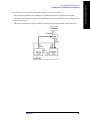
The Sequence Analyzer mode makes it possible to define, save, and execute a series of data acquisitions
(controlled by the analyzer list sequencer) and/or a series of RF stimulus outputs (controlled by the
source list sequencer). This defined series of acquisitions and/or outputs is known as a sequence.
The two list sequencers operate independently; however, they can exchange trigger signals with one
another, and they can both be controlled by the same sequence.
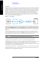
Figure 1-1.
Source and Analyzer List Sequencers
Because one sequence can control both list sequencers, launching a sequence is all that is necessary to
cause the test set to (1) make a set of data acquisitions, (2) make measurements on each acquisition, and
(3) generate whatever RF stimulus is needed during each measurement.
Sequences are typically used in calibration and/or verification of a mobile device. The test set generates
the signals that are expected by the mobile device receiver, and analyzes the signals that the mobile
device transmits in response. This method of interacting with the mobile device saves test time, because
it does not involve any call processing (the test set and the mobile device only need to exchange a
predefined set of signals).
The Sequence Analyzer mode combines speed with flexibility. All of the actions controlled by the
sequence are executed rapidly and without interruption, even if the measurements involved use different
radio standards. (For example, it is possible to switch from an EDGE EVM measurement to a W-CDMA
SEM measurement without stopping the sequence and starting a new one.)
10
Chapter 1
Parameter definitions associated with the source and analyzer list sequencers are defined in Chapter 2 ,
“Analyzer List Sequencer Parameter Definitions,” on page 21 and Chapter 3 , “Source List Sequencer
Parameter Definitions,” on page 35.
NOTE
The analyzer list sequencer uses measurements from other applications on the test set,
and all licensing requirements apply to these applications when they are used in Sequence
Analyzer mode. For example, to make W-CDMA measurements within the analyzer list
sequencer, the W-CDMA U9073A application must be licensed on the test set.
Chapter 1
11
What is the Sequence Analyzer?
What is the Sequence Analyzer?
Sequence Analyzer Introduction
What is the Sequence Analyzer?
What is the Sequence Analyzer?
Sequence Analyzer Introduction
Analyzer List Sequencer
The analyzer list sequencer provides a large amount of flexibility in the capture of an RF signal and the
number of measurements that can be made. Because of this, there are many parameters that the user can
set up to suit particular measurement requirements. The parameters are described in detail in Chapter 2 .
In this section, the higher level concepts are explained with the use of sequence examples.
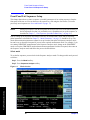
A sequence for the analyzer list sequencer defines one or more data acquisitions (conventionally
represented by a red bar in diagrams). The sequence also defines, within each acquisition, one or more
analysis intervals (time windows for measurement, conventionally represented by a blue bar in
diagrams). Figure 1-2 shows an example of a sequence with two acquisitions (each of which contains
several analysis intervals).
Figure 1-2
Data Sequence
Although one acquisition must end before the next acquisition in the sequence can begin, the analysis
intervals within a given acquisition can overlap as needed. The start and stop times for an analysis
interval can be placed anywhere within the acquisition, so that the measurements associated with that
analysis interval are made only on the desired portion of the acquired data. In this example, the power
level of the measured signal is being stepped downward during the acquisitions, and the analysis
intervals are defined so that some of them occur during a period of unchanging power, while others
include a rising or falling edge.
The need to start a new acquisition arises when there is a change to any of the settings which have been
defined for that acquisition (radio standard, radio band, and so on). If no such changes are made, a single
acquisition is sufficient for the entire sequence.
The need for more than one analysis interval typically arises when two measurements cannot use the
same start and stop times. If one time window within an acquisition is acceptable for all measurements, a
single analysis interval is usually sufficient for the entire acquisition.
12
Chapter 1
User-defined parameters for the sequence determine various important characteristics of the acquisitions
(for example, the frequency of the acquired signal) and of the analysis intervals (for example, the type
and timing of measurements).
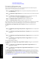
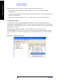
A sequence is saved as a file of tab-separated values representing sequence parameters. The parameters
that are used by the analyzer list sequencer (rather than the source list sequencer) are placed in the file
under the heading: ### Analyzer ###.
The parameters which define an acquisition are placed on one line, followed by one or more lines of
parameters for the analysis intervals within that acquisition. When a sequence is created in a spreadsheet,
the analysis-interval parameters are placed in columns to the right of the acquisition parameters, as
illustrated in Figure 1-3. (When a sequence is saved, leading tabs are inserted into the lines of
analysis-interval parameters, to preserve this spreadsheet format.) In the illustration, there are two
acquisitions (shown in red), of which the first has two analysis intervals (shown in blue) and the second
has four analysis intervals.
Figure 1-3.
Basic Elements of an Analyzer Sequence
In a saved sequence, an acquisition with two analysis intervals would be represented by three lines of
parameters in the file (tabs are represented here by “>”):
### Analyzer ###
1 > GSM > NONE > MS > 1000 > 1 > 0 > LOW > 0.5 > 4.55> VIDeo > -6.5 >
-0.2 > NONE -10
> > > > > > > > > > > > > > 1 > 0.0 > 0.845 > 111 > -4.3
> > > > > > > > > > > > > > 2 > 1.009 > 0.962 > 11 > -12.9
The parameters are described in detail in Chapter 2 .
Chapter 1
13
What is the Sequence Analyzer?
What is the Sequence Analyzer?
Sequence Analyzer Introduction
What is the Sequence Analyzer?
What is the Sequence Analyzer?
Sequence Analyzer Introduction
Source List Sequencer
The signal generator (on the source side of the test set) is used to produce RF stimulus waveforms for use
in calibrating and testing mobile devices. The Source List Sequencer can be used to execute a series of
stimulus operations, in either of two ways:
•
In the Sequence Analyzer mode, the source list sequencer is run by the same sequence which is also
running the analyzer list sequencer. (This is the only way to run both list sequencers at the same
time.) In this case, the lines representing the source sequence parameters are added to the sequence
following the analyzer sequence parameters, as illustrated below in Figure 1-4.)
•
Outside the Sequence Analyzer mode, the source list sequencer can be run independently of the
analyzer list sequencer. (This is can be done from the front panel of the test set by selecting “List
Sequencer” on the Source menu.)
Figure 1-4.
Source Parameters Within a Combined Sequence
For example, two stimulus steps would be represented by two lines of parameters in the sequence file
(tabs are represented here by “>”):
### Source ###
1 > IMM > 1 > PGSM > UP > 30 > -55 > gmsk.wfm > TIME > 4.62 > NONE
2 > IMM > 1.33 > PGSM > UP > 31 > -35 > CONT > COUNt > 13 > NONE
The parameters for the source are described in Chapter 3 . For more detailed information on setting up
the source List Sequencer refer to the Source User’s Guide, which is available as a pdf on the test set and
on the Agilent web.
14
Chapter 1
Example Sequence: Equally Spaced Analysis Intervals
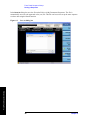
To help further clarify the concepts of sequences, acquisitions and analysis intervals, an example of a
calibration sequence is shown in Figure 1-5. A spreadsheet is used to set up the sequence, acquisition and
analysis interval parameters and subsequently generate a tab separated file which is loaded into the list
sequencers. The use of the spreadsheet is defined in Chapter 7 but in this chapter it is used to help
explain the Sequence Analyzer concepts. The spreadsheet associated with this example is shown in
Figure 1-6.
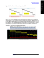
In the diagram in Figure 1-5, a sample sequence of data is shown that could be used for calibrating a
mobile device. The data consists of a PGSM signal on Channel 1, which is stepped in down in power
(from -5 dBm to -47 dBm) over 15 steps. The radio standard is then changed to EGSM on Channel 1, and
the power is stepped down over another 15 steps. The radio standard is then changed back to PGSM, but
on Channel 2, and the power is stepped down again. Finally, the radio standard is changed to EGSM on
Channel 2, and the power is stepped down again.
Figure 1-5
Sequence with Equally Spaced Analysis Intervals
The analyzer sequence which prepares the test set to receive this set of data must be divided into four
acquisitions (one for each of the four radio standard/channel combinations). Each of the four
acquisitions, in turn, must be divided into 15 analysis intervals (one for each of the 15 power levels at
which measurements will be made).
A spreadsheet defining this example sequence is illustrated in Figure 1-6. on page 16.
Chapter 1
15
What is the Sequence Analyzer?
What is the Sequence Analyzer?
Example Sequence: Equally Spaced Analysis Intervals
What is the Sequence Analyzer?
What is the Sequence Analyzer?
Example Sequence: Equally Spaced Analysis Intervals
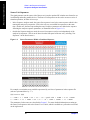
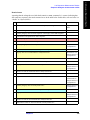
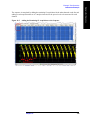
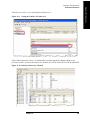
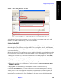
Figure 1-6.
Sequence Spreadsheet
The first row of entries in the spreadsheet sets up the acquisition settings (as represented by the first 18
parameters in the row) for the first acquisition. For example, “1” in the first column specifies that this is
the first acquisition in the sequence, “PGSM” in the third column specifies the radio band, and “1” in the
fifth column specifies the channel number.
Under this row are 18 rows setting up the analysis intervals (that is, the measurement time windows)
within the first acquisition. For each of these, the first 18 parameters are left blank, because these define
the acquisition, and remain unchanged until the next acquisition begins. Only the last five parameters in
the row define the analysis intervals. For example, the 2nd parameter sets the start time for the interval
(as an offset from the start of the acquisition), and the 3rd parameter sets the length of the interval (in this
example, it is consistently 0.533 ms). The 4th parameter is a bit map value which defines the selection of
measurements to be made (see “4: Measurement Bitmap” on page 32). The 5th parameter specifies an
expected DUT output power level for each interval (this value is used to establish pass/fail criteria for
Basic Transmit Power tests, and to ensure that the Instrument Gain setting is not set too high for the test
input to safely receive the DUT signal).
Following the 15 rows defining the analysis intervals for the first acquisition, a new row sets up the
parameters for the second acquisition, and is followed by more rows defining the analysis intervals for
that acquisition.
The parameters for the analyzer list sequencer are described in more detail in Chapter 2 .
In this simple example, the analysis intervals are spaced evenly across the acquisition, and each analysis
interval includes the same measurements. The following example shows how analysis intervals can
overlap as necessary to capture specific sections of data for different measurements.
16
Chapter 1
Example Sequence: Variable Analysis Intervals
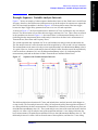
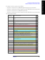
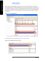
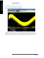
Figure 1-7 shows an example of a data sequence that has three bursts of data. Each burst is at a different
frequency; therefore, three different acquisitions must set up in the analyzer list sequencer to capture this
data. The associated spreadsheet is shown in Figure 1-8. Each acquisition starts at the burst trigger,
because the Input Trigger Delay parameter has been set to zero for each acquisition.
As shown in Figure 1-7, the first acquisition has a duration of 0.72 ms, and includes only one analysis
interval. The interval starts 0.02 ms after the burst trigger, and lasts for 0.7 ms. These values are entered
in the spreadsheet as shown in Figure 1-8. Also entered there is a Measurement Bitmap value of 111
(indicating that the measurements done on this analysis interval are the three basic measurements of
Transmit Power, Phase Error and Frequency Error).
The second acquisition has a duration of 0.74 ms, and includes two analysis intervals rather than one.
The first analysis interval is offset from the start of the acquisition by 0.195 ms and is 0.1 ms in duration.
The measurements are the same as for the previous acquisition (that is, the Measurement Bitmap value is
111 again). However, for the second analysis interval (which is offset from the start of the acquisition by
0.445 ms and has a duration of 0.1 ms), the Measurement Bitmap value is 11 (indicating that the
measurements performed on this data are Basic Transmit Power and Basic Phase Error).
Figure 1-7
Sequence with Variable Analysis Intervals
The third acquisition has a duration of 0.74 ms, and includes three analysis intervals which happen to
overlap in time. The first analysis interval is offset 0.02 ms from the start of the acquisition and lasts 0.7
ms, during which time the basic measurements of Transmit Power, Phase Error and Frequency Error are
done (Measurement Bitmap value 111). The second analysis uses some of the same data used in the first
analysis; it is offset 0.195 ms after the start of the acquisition and lasts 0.1 ms, during which time the
basic measurements of Transmit Power and Phase Error are done (Measurement Bitmap value 11). The
third analysis interval is offset 0.445 ms from the start of the acquisition, and lasts for 0.1 ms, during
Chapter 1
17
What is the Sequence Analyzer?
What is the Sequence Analyzer?
Example Sequence: Variable Analysis Intervals
What is the Sequence Analyzer?
What is the Sequence Analyzer?
Example Sequence: Variable Analysis Intervals
which time the basic measurements of Transmit Power, Phase Error, Frequency Error, and IQ Data are
made (Measurement Bitmap value 1111).
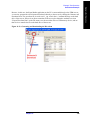
Figure 1-8
Sequence Spreadsheet
18
Chapter 1
Sequence Setup
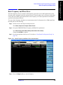
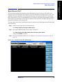
There are a number of ways to set up a Sequence in the test set. The possibilities are described in these
chapters:
•
Front panel setup - see Chapter 6 , “Front Panel Sequence Setup,” on page 77
•
Spreadsheet setup - see Chapter 7 , “List Sequencer Spreadsheet Data Entry,” on page 91
•
Remote setup - see Chapter 10 , “Programming a Sequence,” on page 137 for an example of how to
write a program to set up a Sequence.
See the following chapters for programming commands which are specific to the Sequence Analyzer.
— Chapter 12 , “Basic Measurements Programming Commands,” on page 171
— Chapter 13 , “GSM/EDGE Programming Commands,” on page 181
— Chapter 14 , “W-CDMA Programming Commands,” on page 201
— Chapter 15 , “cdma2000 Programming Commands,” on page 225
— Chapter 16 , “1xEV-DO Programming Commands,” on page 239
— Chapter 17 , “LTE-FDD Programming Commands,” on page 253
— Chapter 18 , “LTE-TDD Programming Commands,” on page 273
— Chapter 19 , “TD-SCDMA Programming Commands,” on page 297
Also, for a more complete SCPI command reference information, refer to the Sequence Analyzer
online help which is available on the test set and also available in pdf format as the “User’s and
Programmer’s Reference” on the C drive of the test set in the C:\Program
Files\Agilent\SignalAnalysis\Infrastructure\Help\bookfiles directory.
To find out how to set up the test set to perform measurements in modes other than the Sequence
Analyzer, refer to the equivalent measurement guides for the modes on the X-series analyzers which are
available at:
http://www.agilent.com/find/mxa
These measurement guides contain the required procedural information
Be aware that the X-series analyzer measurement guides refer to a separate analyzer and signal
generator. For the case of the Agilent EXM test set, the signal generator capability is available on the test
set, so the setup procedures should be adjusted accordingly.
For programming information for the other modes on the test set, refer to the mode online help which is
available on the test set and also available in pdf format as the “User’s and Programmer’s Reference” on
the C drive of the test set in the C:\Program Files\Agilent\SignalAnalysis\Infrastructure\Help\bookfiles
directory.
General programming for the X-series products is documented in the X-series programming guide.
Chapter 1
19
What is the Sequence Analyzer?
What is the Sequence Analyzer?
Sequence Setup
What is the Sequence Analyzer?
What is the Sequence Analyzer?
Sequence Setup
20
Chapter 1
2
Analyzer List Sequencer Parameter Definitions
This chapter describes the parameters that are used in the setup of the analyzer list sequencer. (The
analyzer and source list sequencers can exchange triggers, but are otherwise configured independently.)
The chapter topics are:
•
Analyzer Sequence
•
Acquisition Parameters
•
Analysis Interval Parameters
Analyzer List Sequencer Parameter
Definitions
21
Analyzer List Sequencer Parameter Definitions
Analyzer Sequence
Analyzer Sequence
In the case of the analyzer list sequencer, a sequence is defined as a series of one or more data
acquisitions, each with its own set of measurements to be performed. A sequence is set up so that all the
data needed for the calibration or verification of a device is acquired, and all the required measurement
results are returned in the shortest time possible.
The Sequence allows for the possible wide variation in the parameters of an RF signal from a device
under test. These parameters include frequency and power level. The Sequence also provides
user-specification of measurement triggering and detailed specification of the timing over which
measurements take place. To allow for range variations in the frequency and power level the Sequence
may need to be divided into a series of data acquisitions; an Acquisition is defined in the next section.
There are global parameters associated with a Sequence that must be defined for each Sequence. The
following sections define these parameters. For more information about the parameters and their remote
control commands, refer to the Sequence Analyzer online help (or in pdf format, the User’s and
Programmer’s Reference). Information about how to set these parameters from the front panel and
remotely is provided in “Front Panel List Sequencer Setup” on page 78 and “Set up the List Sequencer
measurement parameters” on page 140.
The measurements within a Sequence that are available are detailed in the following chapters:
Chapter 12 , “Basic Measurements Programming Commands,” on page 171
•
Chapter 13 , “GSM/EDGE Programming Commands,” on page 181
•
Chapter 14 , “W-CDMA Programming Commands,” on page 201
•
Chapter 15 , “cdma2000 Programming Commands,” on page 225
•
Chapter 16 , “1xEV-DO Programming Commands,” on page 239
•
Chapter 17 , “LTE-FDD Programming Commands,” on page 253
•
Chapter 18 , “LTE-TDD Programming Commands,” on page 273
•
Chapter 19 , “TD-SCDMA Programming Commands,” on page 297
Analyzer List Sequencer Parameter
Definitions
•
22
Chapter 2
Analyzer List Sequencer Parameter Definitions
Acquisition Parameters
Acquisition Parameters
Acquisitions, as successive steps in a sequence, make it possible to capture data which varies in
frequency, in power range, and in other characteristics which may require changes to the configuration of
the test set.
This section describes the 14 parameters which configure the test set for a single acquisition. A change to
any of these parameters can be made only by starting a new acquisition; therefore, the number of
acquisitions in the sequence is determined by the number of times that a change is made to one or more
of these parameters. (A single acquisition would be enough for the entire sequence, if none of these
parameters changed.)
An additional 5 parameters are used to define analysis intervals within an acquisition, and those
parameters can be changed repeatedly without starting a new acquisition, as described in “Analysis
Interval Parameters” on page 31.
The parameters which cannot change during an acquisition are described below.
1: Acq Number
Acquisitions are numbered sequentially (1 through n), and executed sequentially. One acquisition must
end before the next acquisition begins.
2: Radio Standard
This parameter specifies a radio standard to be used by the test set’s analyzer for the received signal
during the acquisition. The choices are as follows (for a fixed frequency, select NONE):
NONE
•
GSM
•
EDGE
•
WCDMA [W-CDMA]
•
CDMA2K [cdma2000]
•
CDMA1XEV [1xEVDO]
•
LTE [LTE FDD]
•
LTETDD [LTE TDD]
•
TDSCDMA
•
BTooth [Bluetooth]
•
WLAN
Analyzer List Sequencer Parameter
Definitions
•
Regardless of which choice is made, four basic measurement results (Basic Transmit Power, Basic
Frequency and Phase Error, Basic Discrete PAvT, and Basic IQ data) are always available. The
availability of other measurements depends upon the radio standard selected here, as explained in
connection with Measurement Bitmap (the 20th parameter for the sequence).
Chapter 2
23
Analyzer List Sequencer Parameter Definitions
Acquisition Parameters
The key path for selecting the Radio Standard from the front panel menus is:
[Meas Setup], Acquisition Setup, Radio Setup, Radio Standard
NOTE
A particular radio standard will be available here only if the application for the associated
measurement mode (GSM, for example) is currently loaded.
3: Radio Band
This parameter specifies a radio band appropriate to the radio standard specified in the previous
parameter. The choices are outlined below.
Table 2-1. Values for Radio Band Parameter
Radio Standard
Radio
Band
NONE
NONE
GSM
NONE, PGSM, EGSM, RGSM, DCS1800, PCS1900, GSM450,
GSM480, GSM850, GSM700, TGSM810
or:
Analyzer List Sequencer Parameter
Definitions
EDGE
WCDMA
NONE, BANDI, BANDII, BANDIII, BANDIV, BANDV,
BANDVI, BANDVII, BANDVIII, BANDIX, BANDIX,
BANDX, BANDXI, BANDXII, BANDXIII, BANDXIV
cdma2000
or
1xEVDO
NONE, USCELL, USPCS, JAPAN, KOREAN, NMT, IMT2K,
UPPER, SECOND, PAMR400, PAMR800, IMTEXT,
PCS1DOT9G, AWS, US2DOT5G, PUBLIC, LOWER
LTE FDD
NONE, BAND1, BAND2, BAND3, BAND4, BAND5,
BAND6, BAND7, BAND8, BAND10, BAND11, BAND12,
BAND13, BAND14, BAND17, BAND18, BAND19,
BAND20, BAND21, BAND24, BAND25, BAND26,
BAND27, BAND28, BAND31
LTE TDD
BAND33, BAND34, BAND35, BAND36, BAND37,
BAND38, BAND39, BAND40, BAND41, BAND42,
BAND43, BAND44
TD-SCDMA
BANDA, BANDB, BANDC, BANDD, BANDE, BANDF,
The key path for selecting the Radio Band from the front panel menus is:
[Meas Setup], Acquisition Setup, Radio Setup, Radio Standard, <select standard, then band>
24
Chapter 2
Analyzer List Sequencer Parameter Definitions
Acquisition Parameters
4: Device (for Channel)
This parameter is used by the analyzer to determine the channel plan to be used when computing the
Frequency/Channel values. The choices are BTS (Base Transceiver Station) and MS (Mobile Station).
However, in the initial release of the EXM test set, measurements are supported only for mobile stations;
therefore, MS should always be selected.
The key path for selecting the Device from the front panel menus is:
[Meas Setup], Acquisition Setup, Radio Setup, Device
5: Frequency / Channel
This parameter sets up the analyzer to match the frequency of the received signal. If the radio standard is
other than NONE, this parameter specifies a channel number appropriate to the radio standard, radio
band, and device specified in the previous three parameters. If the radio standard is specified as NONE,
this parameter specifies frequency in MHz.
The key path for setting the Frequency or Channel from the front panel menus is:
[Meas Setup], Acquisition Setup, Frequency [or Channel]
6: Number of Averages
This parameter determines the number of averages (N) for the acquisition. If N is greater than 1, the
analysis intervals for the acquisition are repeated N times, the acquisition period is extended to
accommodate those repetitions, and the measurement results for the repeated analysis intervals are
averaged from all repetitions.
Repetition of analysis intervals does not require re-triggering. The acquisition is still triggered only once.
The key path for setting the Average Count from the front panel menus is:
[Meas Setup], Acquisition Setup, Avg Number
NOTE
The Number of Averages must not be greater than one when the Measurement Bit Mask
(page 32) includes Basic IQ Data.
7: Peak Power
This parameter specifies the highest power level that will be received from the DUT during this
acquisition, in dBm. The information is used by the Auto Set RF Level algorithm to determine the upper
limit of the dynamic range.
Analyzer List Sequencer Parameter
Definitions
The key path for selecting the Peak Power from the front panel menus is:
[Meas Setup], Acquisition Setup, Peak Power
Chapter 2
25
Analyzer List Sequencer Parameter Definitions
Acquisition Parameters
8: Instrument Gain Type
This parameter specifies one of three possible settings which control the input gain of the test set (LOW,
ZERO, or HIGH).
NOTE
This sequence parameter is used by some Agilent models for which Auto Set RF Levels
can be on or off. For E6640A, Auto Set RF Levels is always on, and the test set
automatically selects this setting for the acquisition, so this parameter is ignored by the
sequencer.
9: Transition Time
This parameter specifies a settling-time period which is required between acquisitions, in ms. This
period begins after the time set by the Acquisition Duration parameter, and allows enough time for any
power and frequency changes which are needed for the next acquisition.
NOTE
Although different time units can be used in setting transition time from the front panel,
the parameter value as entered in the sequence is always in ms.
The transition time needed depends on which acquisition parameters are changing between acquisitions.
In most situations, the following suggested values provide adequate transition time.
Changes to instrument gain require a 0.02 ms transition.
Within-band frequency changes require a 0.3 ms transition.
Cross-band frequency changes require a 1 ms transition. The bands are:
•
Frequency Band 1: -0.08 GHz to 0.6075 GHz
•
Frequency Band 2: 0.5075 GHz to 2.1775 GHz
•
Frequency Band 3: 2.0775 GHz to 3.6 GHz
If necessary, add more time to allow for the device under test to change states. If the value entered is
insufficient for the power and frequency changes involved, the sequence will generate an error message
asking for more transition time.
The key path for setting the Transition Time from the front panel menus is:
Analyzer List Sequencer Parameter
Definitions
[Meas Setup], Acquisition Setup, Transition Time
26
Chapter 2
Analyzer List Sequencer Parameter Definitions
Acquisition Parameters
10: Acquisition Duration
This parameter sets the total time for the acquisition (that is, the interval during which the test set is
acquiring IQ samples); the range is 0 to 10 seconds.
If a pre-trigger is set, then the acquisition duration includes the pre-trigger time. A pre-trigger is set by
setting a negative Input Trigger Delay. For no-measurement acquisitions (which are used only to
coordinate the triggering of the test set’s source and analyzer) the Duration should be set to minimum,
and the Meas Bitmap for the single analysis step in the acquisition should be set to zero. The acquisition
Transition Time should then be set to the remaining time that is required for the no-measurement
acquisition.
NOTE
Although different time units can be used in setting the acquisition duration from the front
panel, the parameter value as entered in the sequence is always in ms.
The key path for setting the Acquisition Duration from the front panel menus is:
[Meas Setup], Acquisition Setup, Acquisition Duration
11: Input Trigger (also known as Input Trigger Type)
This parameter specifies how the acquisition is to be triggered. The choices are:
•
IMMediate (equivalent to Free Run); the acquisition is triggered immediately
•
VIDeo; the acquisition is triggered when the IF envelope of the RF input reaches the level defined by
the Input Trigger Level parameter
•
INTernal; the acquisition is triggered from the test set’s source
•
EXTernal1; the acquisition is triggered from the TRIG IN 1 port at the front of the test set
•
EXTernal2; the acquisition is triggered from the TRIG IN 2 port at the front of the test set
The key path for selecting the Input Trigger Type from the front panel menus is:
[Meas Setup], Acquisition Setup, Input Trigger Type
Analyzer List Sequencer Parameter
Definitions
Chapter 2
27
Analyzer List Sequencer Parameter Definitions
Acquisition Parameters
12: Input Trigger Level
This parameter specifies the power level (in dBm) at the RF input which is required to trigger the
acquisition (provided that the Input Trigger Type parameter has been set to “VIDeo”).
The key path for setting the Input Trigger Level from the front panel menus is:
[Meas Setup], Acquisition Setup, Input Trigger Level
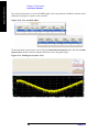
13: Input Trigger Delay
This parameter specifies a time difference between the acquisition trigger (as configured by the two
previous parameters) and the actual start of the acquisition.
Usually the delay is used to move the start of the acquisition to a point slightly after the trigger, to allow
the signal time to settle before it is measured. However, if you want to ensure that a rising edge is
captured, the delay can also be set to a negative value to create a “pre-trigger”: if the parameter value is
-10, the acquisition start is moved to a point 10 ms before the trigger, and data received 10 ms before the
trigger can be included in the measurement results calculation. See Figure 2-1 , “Trigger Delay,” for
illustrations of positive and negative delays.
NOTE
Although different time units can be used in setting the acquisition duration from the front
panel, the parameter value as entered in the sequence is always in ms.
Also: if the value of this parameter is not zero, the acquisition start does not coincide with
the trigger. This needs to be considered when setting the Analysis Offset parameter,
which references the actual start of the acquisition, not the trigger.
The key path for setting the Input Trigger Delay from the front panel menus is:
[Meas Setup], Acquisition Setup, Input Trigger Delay
Trigger Delay
Analyzer List Sequencer Parameter
Definitions
Figure 2-1
28
Chapter 2
Analyzer List Sequencer Parameter Definitions
Acquisition Parameters
14: Output Trigger
This parameter specifies how the test set’s analyzer generates a trigger at the start of an acquisition. The
choices are:
•
NONE; no output trigger is generated
•
INTernal; the output trigger is routed to the test set source
If there is a need to furnish a trigger to the source at the outset of the sequence, before making any
measurements, this can be accomplished by inserting a “dummy step” acquisition (with no analysis
intervals) ahead of the first actual acquisition. This ensures that the source is triggered before the
analyzer begins capturing data.
The key path for selecting the Output Trigger from the front panel menus is:
[Meas Setup], Acquisition Setup, Output Trigger
15: Instrument Gain LOW Value (dB)
NOTE
This sequence parameter is used by some Agilent models for which Auto Set RF Levels
can be on or off. For E6640A, Auto Set RF Levels is always on, and the test set
automatically selects the this setting for the acquisition, so this parameter is ignored by
the sequencer.
16: Multiport Adapter Input Port
This optional parameter specifies which RFIO port of the connected Multiport Adapter will be used as
the input path.
NOTE
This sequence parameter is used by some Agilent models which are designed to operate
in connection with a Multiport Adapter. For E6640A, which does not currently support
that kind of operation, this parameter is ignored by the sequencer.
17: Multiport Adapter Preamp
NOTE
Chapter 2
29
Analyzer List Sequencer Parameter
Definitions
This sequence parameter is used by some Agilent models which are designed to operate
in connection with a Multiport Adapter. For E6640A, which does not currently support
that kind of operation, this parameter is ignored by the sequencer.
Analyzer List Sequencer Parameter Definitions
Acquisition Parameters
18: Acquisition Integration
This optional parameter is used to extend the frequency span and dynamic range capabilities of the
sequence analyzer. There is an IF bandwidth limitation of 40 MHz per acquisition, but it is possible to
divide a measurement across multiple acquisitions in order to capture a larger total bandwidth. The
Acquisition Integration parameter specifies how a given acquisition is to be integrated into a set of
acquisitions.
Measurements which support integration of acquisitions for the purpose of frequency span extension are:
SEM, ACP, and OBW.
Measurements which support integration of acquisitions for the purpose of dynamic range extension are:
TD-SCDMA PvT and LTE-TDD PvT.
Other measurements are performed only on a Normal or Primary acquisition type.
The possible settings are:
•
NORMal: this is acquisition is complete in itself; it is not integrated with other acquisitions.
•
PRIMary: this acquisition is integrated with acquisitions which follow it, for purposes of extending
its frequency span or dynamic range. (Results are stored in this acquisition, not in the Upper, Lower,
or Range acquisitions with which it is integrated.)
•
LOWer: this acquisition is integrated with the last Primary acquisition which precedes it in the
sequence, in order to add a lower extension to the frequency span of the primary. Parameter settings
for this acquisition match those of the primary, except that the Input Trigger is set to Free Run, and
the Center Frequency is equal to the Center Frequency of the Primary minus the IF Bandwidth of the
Primary.
•
UPPer: This acquisition is integrated with the last Primary acquisition which precedes it in the
sequence, in order to add an upper extension to the frequency span of the primary. Parameter settings
for this acquisition match those of the primary, except that the Input Trigger is set to Free Run, and
the Center Frequency is equal to the Center Frequency of the Primary plus the IF Bandwidth of the
Primary.
•
RANGe: this acquisition is integrated with the last Primary acquisition which precedes it in the
sequence, in order to add a lower extension to the dynamic range of the primary. Parameter settings
for this acquisition match those of the primary, except that Input Trigger is Free Run, Peak Power is
-40 dBm, and Expected Power is -70 dBm.
The key path for setting Acquisition Integration from the front panel menus is:
Analyzer List Sequencer Parameter
Definitions
[Meas Setup], Acquisition Setup, Acquisition Integration
30
Chapter 2
Analyzer List Sequencer Parameter Definitions
Analysis Interval Parameters
Analysis Interval Parameters
Each acquisition can include a number of analysis intervals. The intervals are time segments within an
acquisition, during which a specific set of measurements is made. An acquisition can include as many
analysis intervals as necessary, and the intervals can overlap in time (see Figure 1-7 on page 17).
Unlike the first 16 parameters of the sequence, which must remain unchanged during an acquisition, the
last 5 parameters (described below) can be changed as many times as necessary during the same
acquisition (however, any change does require a new analysis interval).
1: Analysis Number
The analysis intervals within an acquisition are numbered (1 through n); this parameter identifies the
analysis interval by number.
This parameter has no purpose beyond identification of a particular analysis interval. The numerical
order of the analysis intervals does not affect measurement timing (for example, the second interval can
start before the first, or after it, or at the same time).
2: Analysis Offset
This parameter sets the delay between the start of the acquisition and the start of the analysis interval.
The actual start of the acquisition is not necessarily coincident with the trigger, unless Input Trigger
Delay (the 13th parameter) is set to zero. Therefore, the trigger delay must be taken into account when
choosing a value for Analysis Offset.
NOTE
Although different time units can be used in setting the analysis offset from the front
panel, the parameter value as entered in the sequence is always in ms.
The key path for setting the Analysis Offset from the front panel menus is:
[Meas Setup], Acquisition Setup, Analysis Step Setup, Analysis Offset
3: Analysis Interval
NOTE
Although different time units can be used in setting the analysis interval from the front
panel, the parameter value as entered in the sequence is always in ms.
The key path for setting the Analysis Interval from the front panel menus is:
[Meas Setup], Acquisition Setup, Analysis Step Setup, Analysis Interval
Chapter 2
31
Analyzer List Sequencer Parameter
Definitions
This parameter sets the length of the analysis interval (that is, the time period during which
measurements are made on the acquired data). Measuring from the start of the acquisition, the analysis
interval begins after the delay specified by the Analysis Offset parameter, and ends after the length
specified by the Analysis Interval parameter.
Analyzer List Sequencer Parameter Definitions
Analysis Interval Parameters
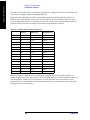
4: Measurement Bitmap
This parameter is a decimal integer, for which the equivalent binary number specifies the set of
measurements to be made during the analysis interval. Each bit in the equivalent binary number
represents one of the available measurements. The selection of a radio standard for the acquisition
determines which measurements are available and which are not, as defined in following table .
The way to determine the appropriate value for the parameter is to select from the available
measurements, and add up their decimal weights (as shown in the rightmost column). For example, to
choose the Occupied BW test (decimal weight 1024) and the Tx Power test (decimal weight 1), set the
parameter value to 1025. This is binary 10000000001, and it selects only those two tests. (This would not
be a possible value in the GSM/EDGE radio standard, which does not support the Occupied BW test.)
The Basic IQ Data measurement (bitmap value “8”) is incompatible with averaging. If the
Average Count parameter for the acquisition is set to a value greater than 1, the analysis
intervals within that acquisition cannot include Basic IQ Data in the Measurement
Bitmap.
Analyzer List Sequencer Parameter
Definitions
NOTE
32
Chapter 2
Analyzer List Sequencer Parameter Definitions
Analysis Interval Parameters
Y
Y
Y
0
1
Basic Freq &
Phase
Y
Y
Y
Y
Y
Y
Y
Y
Y
Y
1
2
Discrete PAvT
Y
Y
Y
Y
Y
Y
Y
Y
Y
Y
2
4
Basic IQ Data
Y
Y
Y
Y
Y
Y
Y
Y
Y
Y
3
8
PvT
Y
Y
Y
Y
4
16
ORFS
Y
Y
5
32
GMSK Ph &
Freq
Y
Y
6
64
EDGE EVM
Y
Y
7
128
8
256
Y
9
512
Bit
ACP
Y
Y
Y
Y
Y
Y
SEM
Y
Y
Y
Y
Y
Y
Occupied BW
Y
Y
Y
Y
Y
Y
Y
Y
10
1024
Mod Accuracy
Y
Y
Y
Y
Y
Y
Y
Y
11
2048
QPSK EVM
Y
Y
Y
12
4096
Code Domain
Y
Y
13
8192
Phase
Discontinuity
Y
14
16384
15
32768
Loopback BER
Y
Y
Y
Y
Decimal Weight
Y
WLAN
Y
Bluetooth
Y
TD-SCDMA
Y
LTE-TDD
Y
LTE-FDD
Y
1xEV-DO
Y
EDGE
Bitmap
Values
cdma2000
Basic TX Power
W-CDMA
Radio Standards
GSM
Available
Measurements
Y
Y
16
65536
LE In-band
Emision
Y
17
131072
18
262144
MIMO EVM
Y
Chapter 2
33
Analyzer List Sequencer Parameter
Definitions
EDR In-band
Spurious
Emission
Analyzer List Sequencer Parameter Definitions
Analysis Interval Parameters
Measurements may differ as to which portion of the acquisition data they need to include. The
Measurement Bitmap for each analysis interval should only include those measurements that use the
same subset of data. To make a measurement which requires different data, add another analysis interval
(with the Analysis Offset and Analysis Interval parameters set appropriately, and the measurement
included in the Measurement Bitmap value).
The key path for selecting the Measurement Bitmap from the front panel menus is:
[Meas Setup], Acquisition Setup, Analysis Step Setup, Measurement Bitmap
5: Expected Power at DUT Output
This parameter specifies the expected power level from the DUT output, in dBm, for this analysis
interval. The value entered here is used by the Basic Transmit Power measurement to verify that the
received power is nominally the same as the value specified in this parameter (upper and lower limits for
DUT output power can be specified as part of the Basic Transmit Power setup).
The lowest value set for this parameter, among the analysis intervals within the acquisition, is also used
by the Auto Set RF Levels algorithm to determine the lower limit of the dynamic range for this
acquisition.
NOTE
For E6640A, Auto Set RF Levels is always on.
The key path for setting the Expected Power from the front panel menus is:
[Meas Setup], Acquisition Setup, Analysis Step Setup, Expected Power at DUT Output
If there is any doubt about what power levels are present at the input to the test set,
measure the power with a power meter and set the attenuation appropriately. Failure to do
so risks damaging the RF circuitry at the test set input.
Analyzer List Sequencer Parameter
Definitions
NOTE
34
Chapter 2
Source List Sequencer Parameter Definitions
This chapter describes the parameters that are used in the setup of the source list sequencer. (The source
and analyzer list sequencers can exchange triggers, but are otherwise configured independently.)
The chapter topics are:
•
Source Sequence
•
Source Parameters
35
Source List Sequencer Parameter
Definitions
3
Source List Sequencer Parameter
Definitions
Source List Sequencer Parameter Definitions
Source Sequence
Source Sequence
A source sequence consists of a series of steps, during each of which an RF waveform is generated by
the test set’s source.
The steps in a source sequence make it possible to generate a succession of RF waveforms, at a variety of
frequencies and power levels, either independently of the analyzer or in coordination with the data
acquisitions which are controlled by the analyzer list sequencer.
The source can generate an output to the device under test at the same time that the analyzer is receiving
data from it; this makes it possible to test a mobile device in simultaneous transmit and receive mode.
36
Chapter 3
Source Parameters
The parameters in the source sequence define the characteristics of the RF waveform to be generated,
and also control the timing and triggering of the sequence steps.
The settings defined by these parameters cannot change during the sequence step. To modify any of these
settings (for example, to change the frequency of the generated waveform), it is necessary to start a new
sequence step.
The 13 parameters which cannot change during a sequence step are described below.
1: Step Number
Source steps are numbered sequentially (1 through n), and executed sequentially. One source step must
end before the next step begins.
2: Step Trigger
This parameter specifies how the source step is to be triggered. The choices are:
•
IMMediate (equivalent to Free Run); the source begins generating a waveform without waiting for a
trigger.
•
KEY; the sequence is halted until the user presses the manual trigger key on the front panel. A popup
window is displayed to indicate that the test set is waiting for the trigger input. (Sending the Bus
Trigger SCPI command while the test set is waiting for a manual trigger had no effect.)
•
BUS; the sequence is halted until the Bus Trigger SCPI command is sent (see the note below). A
popup window is displayed to indicate that the test set is waiting for the trigger input. (Pressing the
manual trigger key while the test set is waiting for the Bus Trigger SCPI command will have no
effect.)
•
INTernal; the source step is triggered from the test set’s analyzer.
•
EXTernal2; the source step is triggered from the TRIG IN 2 port on the rear panel of the test set.
NOTE
The Bus Trigger SCPI command is in the form:
:SOURce:LIST:TRIGger:INITiate[:IMMediate]
The key path for selecting the Step Trigger from the front panel menus is:
[Source], List Sequencer, List Sequencer Setup, Step Trigger
Chapter 3
37
Source List Sequencer Parameter
Definitions
Source List Sequencer Parameter Definitions
Source Parameters
Source List Sequencer Parameter
Definitions
Source List Sequencer Parameter Definitions
Source Parameters
3: Transition Time (also known as Setup Time)
This parameter specifies the time required within a given step to allow the source to settle at the specified
frequency and amplitude settings. Recommended settings are as follows:
•
Frequency change: 0.5 ms
•
Amplitude change to within 1.0 dB: 0.1 ms
•
Amplitude change to within 0.1 dB: 0.02 ms
NOTE
Although different time units can be used in setting the transition time from the front
panel, the parameter value as entered in the sequence is always in ms.
The key path for selecting Setup Time from the front panel menus is:
[Source], List Sequencer, List Sequencer Setup, Transition Time
38
Chapter 3
4: Radio Band
This parameter specifies a radio band to be used. The choices are outlined below (listed beside the radio
standards to which they apply).
Table 3-1. Values for Radio Band Parameter
Radio Standard
Radio
Band
NONE
NONE
GSM
PGSM, EGSM, RGSM, DCS1800, PCS1900, GSM450,
GSM480, GSM850, GSM700, TGSM810
or:
EDGE
WCDMA
BANDI, BANDII, BANDIII, BANDIV, BANDV, BANDVI,
BANDVII, BANDVIII, BANDIX, BANDIX, BANDX,
BANDXI, BANDXII, BANDXIII, BANDXIV
C2K (cdma2000)
USCELL, USPCS, JAPAN, KOREAN, NMT, IMT2K, UPPER,
SECOND, PAMR400, PAMR800, IMTEXT, PCS1DOT9G,
AWS, US2DOT5G, PUBLIC, LOWER
or
C1X (1xEV-DO)
LTE (LTE-FDD)
NONE, BAND1, BAND2, BAND3, BAND4, BAND5,
BAND6, BAND7, BAND8, BAND10, BAND11, BAND12,
BAND13, BAND14, BAND17, BAND18, BAND19,
BAND20, BAND21, BAND24, BAND25, BAND26,
BAND27, BAND28, BAND31
LTE-TDD
BAND33, BAND34, BAND35, BAND36, BAND37,
BAND38, BAND39, BAND40, BAND41, BAND42,
BAND43, BAND44
TD-SCDMA
BANDA, BANDB, BANDC, BANDD, BANDE, BANDF
The key path for selecting Radio Band from the front panel menus is:
[Source], List Sequencer, List Sequencer Setup, Radio Setup, Radio Standard, <select band>
5: Radio Band Link
This parameter specifies the link direction for the present step within the source sequence.The link
direction is used in conjunction with the Radio Band and Channel parameters to determine the output
frequency. \When set to “UP”, the source will calculate the uplink frequency according to an uplink
formula together with selected radio band and channel number. When set to “DOWN”, the source will
calculate the downlink frequency according to a downlink formula together with selected channel band
and channel number.
The key path for selecting Radio Band Link from the front panel menus is:
[Source], List Sequencer, List Sequencer Setup, Radio Setup, Link
Chapter 3
39
Source List Sequencer Parameter
Definitions
Source List Sequencer Parameter Definitions
Source Parameters
Source List Sequencer Parameter
Definitions
Source List Sequencer Parameter Definitions
Source Parameters
6: Frequency/Channel
This parameter specifies the frequency to be generated, either directly (in MHz) or by channel number. If
the radio band specified by the previous parameter is NONE, the present parameter represents the
frequency in MHz; otherwise, the present parameter represents the channel number.
The key path for setting Frequency or Channel from the front panel menus is:
[Source], List Sequencer, List Sequencer Setup, Frequency / Channel
7: Power
This parameter defines the output power level to be generated, in dBm.
The key path for selecting Power from the front panel menus is:
[Source], List Sequencer, List Sequencer Setup, Power
8: Waveform
This parameter specifies the waveform to be generated. The choices are:
•
<Waveform>: the name of a waveform file currently in ARB memory. The supported file types are
.wfm, .bin, and .WAVEFORM.
•
CONT: Continue Previous (that is, continue playback of the waveform from the previous step in the
seequence).
•
CW: Continuous wave (that is, generate an unmodulated tone).
•
OFF: Disables RF output of the test set.
NOTE
If this parameter is set to CONT, the ARB playback will not pause while the source is
retuning to a new frequency or power level which the step may require.
The key path for selecting the Waveform from the front panel menus is:
[Source], List Sequencer, List Sequencer Setup, Waveform
9: Step Duration
This parameter, in combination with the following parameter (Time/Count), determines the duration of
the step. The choices are:
•
TIME: the duration of the step is specified in absolute terms; if this choice is selected, the value of the
Time/Count parameter is interpreted as a duration in ms.
•
COUNt: the duration of the step is specified as the number of times the waveform file in ARB
memory is played; if this choice is selected, the value of the Time/Count parameter is interpreted as a
a waveform playback count. This choice is applicable only if a waveform file is being played; it
cannot be selected if the step has been set up (by the Waveform parameter) to play a CW tone.
•
CONTinuous: if this choice is selected, the step will play continuously until the next step starts.
The key path for selecting the Step Duration from the front panel menus is:
[Source], List Sequencer, List Sequencer Setup, Step Duration
40
Chapter 3
10: Time / Count
This parameter specifies the duration of the step in ms (if the Step Duration parameter has been set to
“TIME”), or as the number of times a waveform file is played (if the Step Duration parameter has been
set to “COUNt”). If the Step Duration parameter has been set to “CONTinuous”, this parameter is
ignored.
The key path for selecting the Duration from the front panel menus is:
[Source], List Sequencer, List Sequencer Setup, Step Duration, Time/Count
11: Output Trigger
This parameter specifies the type of trigger output signal which will be sent at the start of the step. The
choices are:
•
ON: the trigger output is sent to the test set’s analyzer (for triggering of the analyzer list sequencer),
and also to the TRIGGER 2 OUT port at the rear panel of the test set.
•
OFF; no trigger output is generated by the source.
The key path for selecting Output Trigger from the front panel menus is:
[Source], List Sequencer, List Sequencer Setup, Output Trigger
Chapter 3
41
Source List Sequencer Parameter
Definitions
Source List Sequencer Parameter Definitions
Source Parameters
Source List Sequencer Parameter
Definitions
Source List Sequencer Parameter Definitions
Source Parameters
42
Chapter 3
Coordinating the Sequencers
The independence of the list sequencers provides great flexibility, but it also requires careful
coordination of the two, when both are used at once. It is important to manage the order of events, so that
one list sequencer does not proceed before the other is ready.
It is not possible for both sequencers to be initiated absolutely simultaneously. When both are used, the
source list sequencer should always be initiated first. There are two ways to coordinate the sequencers so
that they are initiated in the proper order:
•
Enable Meas Setup, Include Source in Sequence. When this selection is made, both of the list
sequencers are initiated automatically, in the correct order, when you use a command or key to
initiate the analyzer sequence (in this case, the source sequence cannot be initiated independently of
the analyzer sequence).
•
If “Include Source in Sequence” is disabled, then the source and analyzer must be initiated
independently, and the source must be initiated first. This sometimes requires the addition of a
“dummy step” in a sequence, to ensure that the source does not begin playing before the analyzer is
ready to capture data.
This chapter explains how to initiate and trigger the sequencers (when both sequencers are used at the
same time), for alternative test cases.
The chapter topics are:
•
Include Source in Sequence is enabled
•
Include Source in Sequence is disabled
43
Coordinating the Sequencers
4
Coordinating the Sequencers
Coordinating the Sequencers
Include Source in Sequence is enabled
Include Source in Sequence is enabled
When Meas Setup, Include Source in Sequence is enabled, the source cannot be initiated
independently. It is initiated automatically, as described below.
Case 1: Test starts when RF is received by the test set
NOTE
Whenever “Include Source in Sequence” is enabled, it is recommended to set the analyzer
list sequencer to Single mode, by pressing the Single key or by sending the
:INIT:CONT OFF command, to avoid timing problems which could occur in
Continuous mode.
Step 1. Set the Step Trigger parameter of the first step in the source sequence to INTernal (the input
trigger will come from the analyzer list sequencer).
Step 2. Set the Input Trigger parameter of the first acquisition in the analyzer sequence to VIDeo (an
RF burst, to be received from the DUT, triggers the analyzer list sequencer).
Step 3. Set the Output Trigger parameter of the first acquisition in the analyzer sequence to INTernal
(the output trigger will be provided to the source list sequencer).
Step 4. Initiate the analyzer list sequencer, using the Restart key, or by sending the :INIT
command. This initiates the source list sequencer, and arms it to begin running as soon as it
receives the input trigger. Then the analyzer list sequencer is initiated, and armed to begin
running as soon as it is triggered by the DUT’s RF burst. The sequence is executed one time.
44
Chapter 4
Once the sequencers are initiated, the order of events is as follows:
•
The controller begins the non-signalling test by instructing the DUT to transmit an RF signal.
•
The analyzer list sequencer, triggered by the RF Burst received from the DUT, sends a trigger to the
source list sequencer.
•
The source list sequencer begins executing its sequence and generating an RF output to the DUT.
Chapter 4
45
Coordinating the Sequencers
Coordinating the Sequencers
Include Source in Sequence is enabled
Coordinating the Sequencers
Coordinating the Sequencers
Include Source in Sequence is enabled
Case 1A: Test starts when RF is transmitted from the test set
NOTE
Whenever “Include Source in Sequence” is enabled, it is recommended to set the analyzer
list sequencer to Single mode, by pressing the Single key or by sending the
:INIT:CONT OFF command, to avoid timing problems which could occur in
Continuous mode.
Step 1. Set the Step Trigger parameter of the first step in the source sequence to IMMediate (a Free
Run trigger setting).
Step 2. Set the Output Trigger of the first acquisition to NONE. Set the Input Trigger of the
acquisition to VIDeo, and it will be triggered by the RF burst from the DUT.
Step 3. Initiate the analyzer list sequencer, using the Restart key, or by sending the :INIT
command. To begin with, this initiates the source list sequencer. Then the analyzer list
sequencer is initiated, and armed to begin running as soon as it is triggered by the DUT’s RF
burst. The sequence is executed one time.
46
Chapter 4
Once the analyzer list sequencer is initiated, the order of events is as follows:
•
The source list sequencer begins executing its sequence and generating an RF output to the DUT.
•
The analyzer list sequence begins executing its sequence, and measuring the RF input from the DUT.
Chapter 4
47
Coordinating the Sequencers
Coordinating the Sequencers
Include Source in Sequence is enabled
Coordinating the Sequencers
Coordinating the Sequencers
Include Source in Sequence is disabled
Include Source in Sequence is disabled
When Meas Setup, Include Source in Sequence is disabled, the source list sequencer and the analyzer
list sequencer must be initiated separately, as described below.
Case 2: Test starts when RF is received by the test set
Step 1. Set the Trigger parameter of the first step in the source sequence to INTernal (the trigger will
come from the analyzer list sequencer).
Step 2. Set the Input Trigger parameter of the first acquisition in the analyzer sequence to VIDeo (the
trigger will be an RF burst, to be received from the DUT).
Step 3. Set the Output Trigger parameter of the first acquisition in the analyzer sequence to INTernal
(the output trigger will be provided to the source list sequencer).
Step 4. Set the analyzer list sequencer to Single mode, by pressing the Single key or by sending the
:INIT:CONT OFF command.
Step 5. Initiate the source list sequencer, using the Source, List Sequencer, Initiate Sequence key,
or by sending the :SOURce:LIST:TRIG command. This arms the source list sequencer to
begin running as soon as it receives the input trigger from the analyzer list sequencer.
Step 6. Initiate the analyzer list sequencer, using the Restart key, or by sending the :INIT
command. This causes the analyzer list sequencer to execute the sequence one time.
48
Chapter 4
Once the analyzer list sequencer is initiated, the order of events is as follows:
•
The controller begins the non-signalling test by instructing the DUT to transmit an RF signal.
•
The analyzer list sequencer, triggered by the RF Burst received from the DUT, sends a trigger to the
source list sequencer.
•
The source list sequencer begins executing its sequence and generating an RF output to the DUT.
Chapter 4
49
Coordinating the Sequencers
Coordinating the Sequencers
Include Source in Sequence is disabled
Coordinating the Sequencers
Coordinating the Sequencers
Include Source in Sequence is disabled
Case 2A: Test starts when RF is transmitted from the test set
NOTE
This sequence includes an acquisition which has no analysis intervals, and exists only to
generate an output trigger to the source. It is used as a “dummy step”, to ensure that the
source does not begin playing before the analyzer is ready to capture data. The need for a
dummy step arises in this case because (1) the source is to begin playing at the outset of
the test, and (2) “Include Source in Sequence” is not enabled, therefore there is a delay
between initiation of the source and initiation of the analyzer. (Enabling “Include Source
in Sequence” eliminates the need for a dummy step of this kind.)
Step 1. Set the Step Trigger parameter of the first step in the source sequence to INTernal (the trigger
will come from the analyzer list sequencer).
Step 2. Insert a “dummy step” acquisition (with no analysis intervals) ahead of the first acquisition in
the analyzer sequence. As this acquisition is only used to generate a starting trigger for the
source, and makes no measurement, the Acquisition Duration parameter setting can have a
low value (10 us, for example).
Step 3. For the “dummy step” acquisition, set the Input Trigger parameter to IMMediate, and set the
Output Trigger parameter to INTernal (the output trigger will be provided to the source list
sequencer).
Step 4. For the next acquisition, which includes analysis intervals, set the Input Trigger parameter to
VIDeo, and set the Output Trigger parameter to INTernal (the analyzer list sequencer will be
triggered by an RF burst from the DUT, and the output trigger will be provided to the source
list sequencer).
Step 5. Set the analyzer list sequencer to Single mode, by pressing the Single key or by sending the
:INIT:CONT OFF command.
Step 6. Initiate the source list sequencer, using the Source, List Sequencer, Initiate Sequence key,
or by sending the :SOURce:LIST:TRIG command. This arms the source list sequencer to
begin running.
Step 7. Initiate the analyzer list sequencer, using the Restart key, or by sending the :INIT
command. The analyzer list sequencer is initiated, and armed to begin running as soon as it is
triggered by the DUT’s RF burst. The sequence is executed one time.
50
Chapter 4
Once the analyzer list sequencer is initiated, the order of events is as follows:
•
The “dummy step” acquisition causes the analyzer list sequencer to trigger the source list sequencer.
•
The source list sequencer begins executing its sequence and generating an RF output to the DUT.
•
The first “real” acquisition (containing analysis steps) is triggered by the RF input from the DUT.
Chapter 4
51
Coordinating the Sequencers
Coordinating the Sequencers
Include Source in Sequence is disabled
Coordinating the Sequencers
Coordinating the Sequencers
Include Source in Sequence is disabled
52
Chapter 4
Mode Parameters
Mode Parameters
5
This chapter identifies the test set parameters that are set for the entire Sequence.
The chapter topics are:
•
Mode and Measurement Parameters
•
List Sequencer Global Parameters
•
Advanced Setup Parameters
•
Test Set Parameters
— RF inputs and outputs
— Corrections
•
Save and Recall
53
Mode Parameters
Mode Parameters
Mode and Measurement Parameters
Mode and Measurement Parameters
It is possible, in Sequence Analyzer mode, to run certain measurements which belong to other modes
(such as the EDGE/EVM mode). For example, the EDGE EVM measurement, which is one of the
measurements featured in the GSM/EDGE mode, can also be run in Sequence Analyzer mode.
NOTE
Settings for a measurement, or for the mode it belongs to, are not changed by entering or
exiting Sequence Analyzer mode. When you set a parameter for a measurement or mode,
the parameter retains that value until you make another specific change to it, regardless of
whether the test set is placed in Sequence Analyzer mode or in the native mode of the
measurement. (Returning to a previous mode does not restore previous settings.)
The present chapter describes parameters that apply to a measurement mode and all of its measurements,
and can be changed from within the Sequence Analyzer mode (by remote command only).
For information on parameters that pertain to a specific measurement within a measurement mode, and
and be changed from within the Sequence Analyzer mode, see the following chapters:
•
Chapter 13 , “GSM/EDGE Programming Commands,” on page 181
•
Chapter 14 , “W-CDMA Programming Commands,” on page 201
•
Chapter 15 , “cdma2000 Programming Commands,” on page 225
•
Chapter 16 , “1xEV-DO Programming Commands,” on page 239
•
Chapter 17 , “LTE-FDD Programming Commands,” on page 253
•
Chapter 18 , “LTE-TDD Programming Commands,” on page 273
•
Chapter 19 , “TD-SCDMA Programming Commands,” on page 297
The commands used here to set measurement mode parameters (from within the Sequence Analyzer
mode) are almost the same as the commands which would be used outside the Sequence Analyzer mode;
the only difference is the addition of LSEQuencer:<modename> nodes to each command.
For example, [:SENSe]:RADio:PSHape WIDE becomes
[:SENSe]:LSEQuencer:EDGE:RADio:PSHape WIDE.
NOTE
“EDGE” (and not “GSM”) is used to designate the GSM/EDGE mode in commands.
As explained above, a parameter change which is made in this way remains in effect even after the test
set is no longer in Sequence Analyzer mode. Selecting GSM/EDGE mode would not undo a
GSM/EDGE setting change that was made in Sequence Analyzer mode.
The settings apply for the whole Sequence (not just for a particular acquisition), and should be set up
prior to starting the Sequence.
54
Chapter 5
Mode Parameters
Mode and Measurement Parameters
Time Slot setting for GSM mode. Provides an On/Off for each timeslot (0 to 7). Generally used only with
periodic and ext frame triggers. For more details about the command see the GSM/EDGE online help (or
in pdf format, the User’s and Programmer’s Reference).
[:SENSe]:LSEQuencer:EDGE:CHANnel:SLOT <integer>
[:SENSe]:LSEQuencer:EDGE:CHANnel:SLOT?
[:SENSe]:LSEQuencer:EDGE:CHANnel:SLOT:AUTO OFF|ON|0|1
[:SENSe]:LSEQuencer:EDGE:CHANnel:SLOT:AUTO?
GSM Burst Type
Burst Type setting for GSM mode. Specifies the burst type that the test set searches for, and to which it
synchronizes. For more details about the command see the GSM/EDGE online help (or in pdf format, the
User’s and Programmer’s Reference).
Choices:
•
Sync (SCH)
•
Access (RACH)
•
Normal - NB (TCH and CCH)
•
Higher Symbol Rate - HB (TCH and CCH); requires EDGE Evolution U9071A-3FP to be installed
•
Mixed (NB/HB for TSC sync); requires EDGE Evolution U9071A-3FP to be installed
[:SENSe]:LSEQuencer:EDGE:CHANnel:BURSt NORMalSYNC|ACCess|HSRate|MIXed
[:SENSe]:LSEQuencer:EDGE:CHANnel:BURSt?
GSM TSC
TSC setting for GSM mode. Allows you to select the Training Sequence Code that determines which
burst is to be measured. Applicable only when the selected GSM measurement requires a burst sync of
type "Training Sequence". For more details about the command see the GSM/EDGE online help (or in
pdf format, the User’s and Programmer’s Reference).
[:SENSe]:LSEQuencer:EDGE:CHANnel:TSCode <integer>
[:SENSe]:LSEQuencer:EDGE:CHANnel:TSCode?
GSM Mod Scheme
Modulation scheme setting for GSM mode. Selects the Modulation Scheme (modulation type) for
Normal Burst that the test set searches for when Auto mode is selected. For more details about the
command see the GSM/EDGE online help (or in pdf format, the User’s and Programmer’s Reference).
[:SENSe]:LSEQuencer:EDGE:SYNC:NORMal:MODulation:AUTO ON|OFF|1|0
[:SENSe]:LSEQuencer:EDGE:SYNC:NORMal:MODulation:AUTO?
Chapter 5
55
Mode Parameters
GSM Timeslot
Mode Parameters
Mode Parameters
Mode and Measurement Parameters
GSM Burst Search Threshold
Burst Search Threshold setting for GSM mode. Sets the relative power threshold from the peak power,
which is used by the burst alignment algorithm to determine the burst rising edge and falling edge. For
more details about the command see the GSM/EDGE online help (or in pdf format, the User’s and
Programmer’s Reference).
[:SENSe]:LSEQuencer:EDGE:SYNC:BURSt:STHReshold <rel_ampl>
[:SENSe]:LSEQuencer:EDGE:SYNC:BURSt:STHReshold?
GSM HSR Pulse Shape Filter
HSR Pulse Shaping Filter setting for GSM mode. Selects the pulse shaping filter for higher symbol rate
(HSR) signals. For more details about the command see the GSM/EDGE online help (or in pdf format,
the User’s and Programmer’s Reference).
This functionality applies only to the following measurements:
•
EDGE EVM Measurement
•
EDGE Power vs. Time Measurement
•
GMSK/EDGE Output RF Spectrum measurement
Requires EDGE Evolution U9071A-3FP to be installed.
[:SENSe]:LSEQuencer:EDGE:RADio:PSHape NARRow|WIDE
[:SENSe]:LSEQuencer:EDGE:RADio:PSHape?
GSM Burst Align
Burst Align setting for GSM mode. Selects the sync alignment to be either to the GSM standard or the
standard offset by a half bit behind. For more details about the command see the GSM/EDGE online help
(or in pdf format, the User’s and Programmer’s Reference).
[:SENSe]:LSEQuencer:EDGE:SYNC:ALIGnment GSM|HBIT
[:SENSe]:LSEQuencer:EDGE:SYNC:ALIGnment?
GSM Carrier Bandpass Filter
Carrier Bandpass Filter setting for GSM mode. Select Multiple or Single to enable or disable the
multi-carrier tolerance filter. For more details about the command see the GSM/EDGE online help (or in
pdf format, the User’s and Programmer’s Reference).
[:SENSe]:LSEQuencer:EDGE:RADio:CARRier:NUMBer SINGle|MULTiple
[:SENSe]:LSEQuencer:EDGE:RADio:CARRier:NUMBer?
56
Chapter 5
Mode Parameters
Mode and Measurement Parameters
RF Sync Delay setting for GSM mode. Adjusts the "T0" point that has been measured in each
measurement. This adjustment does not apply if the Burst Sync key (in each measurement's Meas Setup
menu) is set to None. For more details about the command see the GSM/EDGE online help (or in pdf
format, the User’s and Programmer’s Reference).
[:SENSe]:LSEQuencer:EDGE:SYNC:BURSt:RFAMplitude:DELay <time>
[:SENSe]:LSEQuencer:EDGE:SYNC:BURSt:RFAMplitude:DELay?
WCDMA HSDPA/HSUPA Enable
HSDPA/HSUPA Enable setting for WCDMA mode. Allows you to specify the HSDPA/HSUPA option
enable as On or Off. This selection is necessary because some of the auto detection functions which are
expecting an HSPA signal are less tolerant when the signal is noisy or distorted; it should be off when an
HSPA signal is not expected. For more details about the command see the W-CDMA online help (or in
pdf format, the User’s and Programmer’s Reference).
[:SENSe]:LSEQuencer:WCDMa:RADio:CONFigure:HSDPa[:STATe] 0|1|ON|OFF
[:SENSe]:LSEQuencer:WCDMa:RADio:CONFigure:HSDPa[:STATe]?
1xEV-DO Physical Layer SubType
Physical Layer Subtype setting for1xEV-DO mode. Allows you to select the subtype used in
measurement. For more details about the command see the 1xEV-DO online help (or in pdf format, the
User’s and Programmer’s Reference).
[:SENSe]:LSEQuencer:EVDO:RADio:PLSubtype SUB0|SUB2|SUB3
[:SENSe]:LSEQuencer:EVDO:RADio:PLSubtype?
1xEV-DO Pre-define Offset/Interval
Pre-defined Offset/Interval setting for 1xEV-DO mode. Allows you to select a desired slot (the
possibilities are Idle Slots 1 & 2, Half Slots 1 & 2, Pilot 1 & 2, MAC 1 through 4, and Full Slot). For
more details about the command see the 1xEV-DO online help (or in pdf format, the User’s and
Programmer’s Reference).
[:SENSe]:LSEQuencer:EVDO:STYPe
IS1|IS2|HS1|HS2|PIL1|PIL2|MAC1|MAC2|MAC3|MAC4|FS
[:SENSe]:LSEQuencer:EVDO:STYPe?
TD-SCDMA Analysis Timeslot
Analysis timeslot setting for TD-SCDMA mode. It specifies which sub-frames timeslot, within the
selected Sub-frame, is used for analysis and trace data measurement results. The available selections
include timeslots 0 through 6, the DwPTS and UpPTS timeslots. For more details about the command see
the TD-SCDMA online help (or in pdf format, the User’s and Programmer’s Reference).
[:SENSe]:LSEQuencer:TDSCdma:SLOT TS0|TS1|TS2|TS3|TS4|TS5|TS6|UPTS|DPTS
Chapter 5
57
Mode Parameters
GSM RF Sync Delay
Mode Parameters
Mode Parameters
Mode and Measurement Parameters
[:SENSe]:LSEQuencer:TDSCdma:SLOT?
TD-SCDMA HSPA/8PSK Enable
HSPA/8PSK Enable setting for TD-SCDMA mode. (This feature requires installation of the HSPA/8PSK
option license.) For more details about the command see the TD-SCDMA online help (or in pdf format,
the User’s and Programmer’s Reference).
[:SENSe]:LSEQuencer:TDSCdma:RADio:CONFigure:HSDPa[:STATe] 0|1|OFF|ON
[:SENSe]:LSEQuencer:TDSCdma:RADio:CONFigure:HSDPa[:STATe]??
TD-SCDMA Demod – Scramble Code
Scramble Code setting for TD-SCDMA mode. The available range is 0 ~ 127. For more details about the
command see the TD-SCDMA online help (or in pdf format, the User’s and Programmer’s Reference).
[:SENSe]:LSEQuencer:TDSCdma:TDEMod:SCODe <integer>
[:SENSe]:LSEQuencer:TDSCdma:TDEMod:SCODe?
TD-SCDMA Demod – Uplink Pilot
Uplink Pilot setting for TD-SCDMA mode. It specifies the Uplink Pilot synchronization ID sequence
(SYNC-UL). The available range is 0 ~ 255. For more details about the command see the TD-SCDMA
online help (or in pdf format, the User’s and Programmer’s Reference).
[:SENSe]:LSEQuencer:TDSCdma:TDEMod:UPTS <integer>
[:SENSe]:LSEQuencer:TDSCdma:TDEMod:UPTS?
TD-SCDMA Demod – Sync Type
Sync Type setting for TD-SCDMA mode. The available selections include Pilot, Midamble and Trigger.
Pilot synchronization searches for either the Uplink Pilot or Downlink Pilot burst and then uses the
location of that burst to position all of the rest of the time slots. Synchronization will fail if neither pilot
burst is found or if the incorrect Uplink or Downlink Pilot Code ID is set for the Pilot burst present.
Midamble synchronization searches for the first Uplink traffic burst, positioning it as timeslot TS1.
Synchronization will fail if there are Pilot bursts present, if TS0 is present, if there are no traffic bursts
present or if the incorrect Basic Midamble Code ID is set. Trigger synchronization deems the position of
the trigger as the start of the frame of the TD-SCDMA signal. For more details about the command see
the TD-SCDMA online help (or in pdf format, the User’s and Programmer’s Reference).
[:SENSe]:LSEQuencer:TDSCdma:TDEMod:SYNC PILot|MIDamble|TRIgger
[:SENSe]:LSEQuencer:TDSCdma:TDEMod:SYNC?
TD-SCDMA Demod – Switching Point
Switching Point setting for TD-SCDMA mode. Switching Point is the timeslot number of the last uplink
traffic timeslot. Timeslots from the following (next higher numbered) traffic timeslot through the end of
the sub-frame are treated as downlink timeslots. For more details about the command see the
TD-SCDMA online help (or in pdf format, the User’s and Programmer’s Reference).
58
Chapter 5
Mode Parameters
Mode and Measurement Parameters
Mode Parameters
[:SENSe]:LSEQuencer:TDSCdma:TDEMod:ULSPoint <integer>
[:SENSe]:LSEQuencer:TDSCdma:TDEMod:ULSPoint?
TD-SCDMA Demod – Max Users for Traffic TS0
Max Users for Traffic TS0 setting for TD-SCDMA mode. It specifies the number of Maximum Users
that will be associated with the timeslots 0. The range is 2 ~ 16. For more details about the command see
the TD-SCDMA online help (or in pdf format, the User’s and Programmer’s Reference).
[:SENSe]:LSEQuencer:TDSCdma:TDEMod:MXUSer:TS0 <integer>
[:SENSe]:LSEQuencer:TDSCdma:TDEMod:MXUSer:TS0?
TD-SCDMA Demod – Max Users for Traffic TS1
Max Users for Traffic TS1 setting for TD-SCDMA mode. It specifies the number of Maximum Users
that will be associated with the timeslots 1. The range is 2 ~ 16. For more details about the command see
the TD-SCDMA online help (or in pdf format, the User’s and Programmer’s Reference).
[:SENSe]:LSEQuencer:TDSCdma:TDEMod:MXUSer:TS1 <integer>
[:SENSe]:LSEQuencer:TDSCdma:TDEMod:MXUSer:TS1?
TD-SCDMA Demod – Max Users for Traffic TS2
Max Users for Traffic TS2 setting for TD-SCDMA mode. It specifies the number of Maximum Users
that will be associated with the timeslots 2. The range is 2 ~ 16. For more details about the command see
the TD-SCDMA online help (or in pdf format, the User’s and Programmer’s Reference).
[:SENSe]:LSEQuencer:TDSCdma:TDEMod:MXUSer:TS2 <integer>
[:SENSe]:LSEQuencer:TDSCdma:TDEMod:MXUSer:TS2?
TD-SCDMA Demod – Max Users for Traffic TS3
Max Users for Traffic TS3 setting for TD-SCDMA mode. It specifies the number of Maximum Users
that will be associated with the timeslots 3. The range is 2 ~ 16. For more details about the command see
the TD-SCDMA online help (or in pdf format, the User’s and Programmer’s Reference).
[:SENSe]:LSEQuencer:TDSCdma:TDEMod:MXUSer:TS3 <integer>
[:SENSe]:LSEQuencer:TDSCdma:TDEMod:MXUSer:TS3?
TD-SCDMA Demod – Max Users for Traffic TS4
Max Users for Traffic TS4 setting for TD-SCDMA mode. It specifies the number of Maximum Users
that will be associated with the timeslots 4. The range is 2 ~ 16. For more details about the command see
the TD-SCDMA online help (or in pdf format, the User’s and Programmer’s Reference).
[:SENSe]:LSEQuencer:TDSCdma:TDEMod:MXUSer:TS4 <integer>
[:SENSe]:LSEQuencer:TDSCdma:TDEMod:MXUSer:TS4?
Chapter 5
59
Mode Parameters
Mode Parameters
Mode and Measurement Parameters
TD-SCDMA Demod – Max Users for Traffic TS5
Max Users for Traffic TS5 setting for TD-SCDMA mode. It specifies the number of Maximum Users
that will be associated with the timeslots 5. The range is 2 ~ 16. For more details about the command see
the TD-SCDMA online help (or in pdf format, the User’s and Programmer’s Reference).
[:SENSe]:LSEQuencer:TDSCdma:TDEMod:MXUSer:TS5 <integer>
[:SENSe]:LSEQuencer:TDSCdma:TDEMod:MXUSer:TS5?
TD-SCDMA Demod – Max Users for Traffic TS6
Max Users for Traffic TS6 setting for TD-SCDMA mode. It specifies the number of Maximum Users
that will be associated with the timeslots 6. The range is 2 ~ 16. For more details about the command see
the TD-SCDMA online help (or in pdf format, the User’s and Programmer’s Reference).
[:SENSe]:LSEQuencer:TDSCdma:TDEMod:MXUSer:TS6 <integer>
[:SENSe]:LSEQuencer:TDSCdma:TDEMod:MXUSer:TS6?
TD-SCDMA Demod – Slot Frequency Reference
Slot Frequency Reference setting for TD-SCDMA mode. It specifies whether the appropriate pilot
timeslot or the midamble section of the timeslot will be used as the frequency and phase reference for an
individual traffic timeslot. For more details about the command see the TD-SCDMA online help (or in
pdf format, the User’s and Programmer’s Reference).
[:SENSe]:LSEQuencer:TDSCdma:TDEMod:SREFerence PILot|MIDamble
[:SENSe]:LSEQuencer:TDSCdma:TDEMod:SREFerence?
TD-SCDMA Demod – Code Channel Detection
Code Channel Detection setting for TD-SCDMA mode. If the current timeslot is DwPTS or UpPTS, its
value will be set to AUTO. For more details about the command see the TD-SCDMA online help (or in
pdf format, the User’s and Programmer’s Reference).
[:SENSe]:LSEQuencer:TDSCdma:TDEMod:CDCHannel:DETection AUTO|MAN
[:SENSe]:LSEQuencer:TDSCdma:TDEMod:CDCHannel:DETection?
TD-SCDMA Demod – Mod Scheme
Modulation Scheme setting for TD-SCDMA mode. (This setting can be made only if the HSPA/8PSK
option license is installed and Enable HSPA/8PSK is ON; otherwise the value is fixed at AUTO.) If the
Mod Scheme is MAN, you must specify the modulation format for each channel. If the Mod Scheme is
Auto, the measurement will automatically detect the channel’s modulation format. If the current timeslot
is DwPTS or UpPTS, its value will be set to AUTO. The Auto mode is only applied to QPSK, 8PSK and
16QAM. For 64QAM, only MAN mode is supported.
The Auto mode is only applied to QPSK, 8PSK and 16QAM. For 64QAM, it only supports MAN mode.
For more details about the command see the TD-SCDMA online help (or in pdf format, the User’s and
Programmer’s Reference).
60
Chapter 5
Mode Parameters
Mode and Measurement Parameters
Mode Parameters
[:SENSe]:LSEQuencer:TDSCdma:TDEMod:MODScheme:AUTO 1|0|ON|OFF
[:SENSe]:LSEQuencer:TDSCdma:TDEMod:MODScheme:AUTO?
TD-SCDMA Demod – Scramble Code
Scramble Code setting for TD-SCDMA mode. The available range is 0 ~ 127. For more details about the
command see the TD-SCDMA online help (or in pdf format, the User’s and Programmer’s Reference).
[:SENSe]:LSEQuencer:TDSCdma:TDEMod:SCODe <integer>
[:SENSe]:LSEQuencer:TDSCdma:TDEMod:SCODe?
TDSCDMA Demod – Channel Configuration
The following set of commands allows you to specify the parameters for the channel. They are
unavailable when “Code Channel Detection” and “Mod Scheme” are both AUTO.
•
Select Code Length
•
Select All Code Channels
•
Select Code Channel
•
Code Channel Status
•
Midamble Shift
•
Modulation Format
•
Phase Shift
•
Phase Shift Detection
TD-SCDMA Select Code Length
Select Code Length in Channel Configuration setting for TD-SCDMA mode. The available selections
include 1, 2, 4, 8 and 16. For more details about the command see the TD-SCDMA online help (or in pdf
format, the User’s and Programmer’s Reference).
[:SENSe]:LSEQuencer:TDSCdma:TDEMod:SCLength <integer>
[:SENSe]:LSEQuencer:TDSCdma:TDEMod:SCLength?
TD-SCDMA Select All Code Channels
Select All Code Channels in Channel Configuration setting for TD-SCDMA mode. If the Select All
Code Channels is ON, by modifying the modulation format or the midamble shift, the user can change
the values of all code channels which have the same code length and at the same time, the Select Code
Channel key will be unavailable. For more details about the command see the TD-SCDMA online help
(or in pdf format, the User’s and Programmer’s Reference).
[:SENSe]:LSEQuencer:TDSCdma:TDEMod:CDCHannel:SALL 1|0|ON|OFF
[:SENSe]:LSEQuencer:TDSCdma:TDEMod:CDCHannel:SALL?
Chapter 5
61
Mode Parameters
Mode Parameters
Mode and Measurement Parameters
TD-SCDMA Select Code Channel
Select Code Channel in Channel Configuration setting for TD-SCDMA mode. The max value for the
code Channel should be (Select Code length – 1). The Dispread Channel Code Channel is used, along
with the Dispread Channel Spread Code Length, to specify the active code channel and layer used for the
channel trace data measurement results. This is unavailable if Select All Code Channel is ON. For more
details about the command see the TD-SCDMA online help (or in pdf format, the User’s and
Programmer’s Reference).
[:SENSe]:LSEQuencer:TDSCdma:TDEMod:CDCHannel <integer>
[:SENSe]:LSEQuencer:TDSCdma:TDEMod:CDCHannel?
TD-SCDMA Code Channel Status
Code Channel Status in Channel Configuration setting for TD-SCDMA mode. This is unavailable when
“Code Channel Detection” is AUTO. For more details about the command see the TD-SCDMA online
help (or in pdf format, the User’s and Programmer’s Reference).
[:SENSe]:LSEQuencer:TDSCdma:TDEMod:CDCHannel:ACTive
<spread_code_length>,<code_channel>,0|1|OFF|ON
[:SENSe]:LSEQuencer:TDSCdma:TDEMod:CDCHannel:ACTive?
<spread_code_length>,<code_channel>
TD-SCDMA Midamble Shift
Midamble Shift in Channel Configuration setting for TD-SCDMA mode. The range is 1 ~ 16. For more
details about the command see the TD-SCDMA online help (or in pdf format, the User’s and
Programmer’s Reference).
[:SENSe]:LSEQuencer:TDSCdma:TDEMod:MSHift
<spread_code_length>,<code_channel>,<integer>
[:SENSe]:LSEQuencer:TDSCdma:TDEMod:MSHift?
<spread_code_length>,<code_channel
TD-SCDMA Modulation Format
Modulation Format in Channel Configuration setting for TD-SCDMA mode. If Auto is assigned to a
code channel with some spread code length, the modulation format on this code channel will be
determined by the measurement. For more details about the command see the TD-SCDMA online help
(or in pdf format, the User’s and Programmer’s Reference).
[:SENSe]:LSEQuencer:TDSCdma:TDEMod:MODFormat
<integer>,<integer>,AUTO|QPSK|PSK8|QAM16|QAM64
[:SENSe]:LSEQuencer:TDSCdma:TDEMod:MODFormat? <integer>,<integer>
TD-SCDMA Phase Shift
Phase Shift in Channel Configuration setting for TD-SCDMA mode. The range is -360.0 ~ 360.0 degree.
For more details about the command see the TD-SCDMA online help (or in pdf format, the User’s and
Programmer’s Reference).
[:SENSe]:LSEQuencer:TDSCdma:TDEMod:PHASe:SHIFt <integer>,<integer>,<real>
62
Chapter 5
Mode Parameters
Mode and Measurement Parameters
TD-SCDMA Phase Shift Detection
Phase Shift Detection in Channel Configuration setting for TD-SCDMA mode. For more details about
the command see the TD-SCDMA online help (or in pdf format, the User’s and Programmer’s
Reference).
[:SENSe]:LSEQuencer:TDSCdma:TDEMod:PHASe:SHIFt:DETection:AUTO ON|OFF|1|0
[:SENSe]:LSEQuencer:TDSCdma:TDEMod:PHASe:SHIFt:DETection:AUTO?
TD-SCDMA Demod – Timing Reference
Timing Reference setting for TD-SCDMA mode. The available selections include DwPTS, UpPTS and
Trigger. For more details about the command see the TD-SCDMA online help (or in pdf format, the
User’s and Programmer’s Reference).
[:SENSe]:LSEQuencer:TDSCdma:TDEMod:TREFerence DPTS|UPTS|TRIG
[:SENSe]:LSEQuencer:TDSCdma:TDEMod:TREFerence?
TD-SCDMA Demod – Filter Alpha
Filter Alpha setting for TD-SCDMA mode. It specifies the measurement filter (Root-raised Cosine)
alpha. For more details about the command see the TD-SCDMA online help (or in pdf format, the User’s
and Programmer’s Reference).
[:SENSe]:LSEQuencer:TDSCdma:TDEMod:ALPHa <real>
[:SENSe]:LSEQuencer:TDSCdma:TDEMod:ALPHa?
TD-SCDMA Demod – Active Slot Threshold
Active Slot Threshold setting for TD-SCDMA mode. It specifies the Active Slot detection threshold.
The unit is dBc (dB below the slot with the largest measured power). For more details about the
command see the TD-SCDMA online help (or in pdf format, the User’s and Programmer’s Reference).
[:SENSe]:LSEQuencer:TDSCdma:TDEMod:THReshold:SLOT <real>
[:SENSe]:LSEQuencer:TDSCdma:TDEMod:THReshold:SLOT?
TD-SCDMA Demod – Active Channel Threshold
Active Channel Threshold setting for TD-SCDMA mode. Active Channel Threshold lets you set the
threshold above which a code channel is detected active and included in the Composite Reference
waveform. The units are dBc (dB below the total power within the Analysis Timeslot). For more details
about the command see the TD-SCDMA online help (or in pdf format, the User’s and Programmer’s
Reference).
[:SENSe]:LSEQuencer:TDSCdma:TDEMod:THReshold:CHANnel <real>
[:SENSe]:LSEQuencer:TDSCdma:TDEMod:THReshold:CHANnel?
[:SENSe]:LSEQuencer:TDSCdma:TDEMod:THReshold:CHANnel:AUTO ON|OFF|0|1
Chapter 5
63
Mode Parameters
[:SENSe]:LSEQuencer:TDSCdma:TDEMod:PHASe:SHIFt? <integer>,<integer>?
Mode Parameters
Mode Parameters
Mode and Measurement Parameters
[:SENSe]:LSEQuencer:TDSCdma:TDEMod:THReshold:CHANnel:AUTO?
TD-SCDMA Demod – EVM Result IQ Offset
EVM Result IQ Offset setting for TD-SCDMA mode. The available selections include Standard and
Exclude. For more details about the command see the TD-SCDMA online help (or in pdf format, the
User’s and Programmer’s Reference).
[:SENSe]:LSEQuencer:TDSCdma:TDEMod:EVMResult:IQOFfset STANdard|EXClude
[:SENSe]:LSEQuencer:TDSCdma:TDEMod:EVMResult:IQOFfset?
TD-SCDMA Demod – Mirror Frequency Spectrum
Mirror Frequency Spectrum setting for TD-SCDMA mode. The available selections include Normal and
Invert. For more details about the command see the TD-SCDMA online help (or in pdf format, the
User’s and Programmer’s Reference).
[:SENSe]:LSEQuencer:TDSCdma:TDEMod:SPECtrum:MIRRor NORMal|INVert
[:SENSe]:LSEQuencer:TDSCdma:TDEMod:SPECtrum:MIRRor?
TD-SCDMA Demod – Limit Test
Limit Test setting for TD-SCDMA mode. For more details about the command see the TD-SCDMA
online help (or in pdf format, the User’s and Programmer’s Reference).
[:SENSe]:LSEQuencer:TDSCdma:TDEMod:NORMalize 1|0|ON|OFF
[:SENSe]:LSEQuencer:TDSCdma:TDEMod:NORMalize?
TD-SCDMA Demod – Multi-Carrier Demod
Multi-Carrier Demod setting for TD-SCDMA mode. For more details about the command see the
TD-SCDMA online help (or in pdf format, the User’s and Programmer’s Reference).
[:SENSe]:LSEQuencer:TDSCdma:TDEMod:MCARrier 1|0|ON|OFF
[:SENSe]:LSEQuencer:TDSCdma:TDEMod:MCARrier?
64
Chapter 5
Mode Parameters
List Sequencer Global Parameters
In addition to the mode and measurement parameters that are set for a sequence, there are also
parameters that configure the source and analyzer list sequencers. These parameters can be set up from
the front panel or by remote control SCPI commands. For details on how to set up these parameters from
the front panel see Chapter 6 , “Front Panel Sequence Setup,” on page 77.
NOTE
Global parameters cannot be specific to an acquisition; they apply to the entire sequence
and to every acquisition in it.
Trigger Timeout
This parameter sets the timeout for trigger events that occur during a sequence. If all Acquisition
Parameters triggers are set to Free Run, this parameter is ignored. This parameter should be set to a value
that exceeds the trigger arming period (the time between the previous acquisition completing and the
next trigger). This parameter can be switched ON or OFF. When it is ON, you need to specify a timeout
value.
If the Trigger Timeout is ON, and is set to a value greater than the trigger arming period, then the Trigger
Timeout is activated on the next non-Free Run trigger in the Sequence. No timeout error is recorded.
If Trigger Timeout is ON, and is set to a value less than the trigger arming period, then an error is flagged
and is displayed on the front panel; it can also be returned remotely by sending the command
SYSTem:ERRor? (The sequence is aborted only if Abort on Error is set to ON.)
The remote command for activating or deactivating the timeout is:
[:SENSe]:LSEQuencer:TIMeout:TRIGger:STATe OFF|ON|0|1
The remote command for setting the value of the timeout is:
[:SENSe]:LSEQuencer:TIMeout:TRIGger <time>
Abort on Limit Fail
This parameter specifies whether or not the test set aborts during a Sequence if any of the measurements
in the Sequence exceed the limits set for that measurement. This only applies to measurements which
have test limit parameters and which are enabled.
The remote command for this parameter is:
[:SENSe]:LSEQuencer:ABORt:LIMit:FAIL[:STATE] ON|OFF|0|1
Chapter 5
65
Mode Parameters
List Sequencer Global Parameters
Mode Parameters
Mode Parameters
List Sequencer Global Parameters
Abort on Error
This parameter specifies whether or not the test set aborts during a sequence if the test set returns an error
for any of the measurements in the sequence. If set to ON, this parameter causes the list sequencer to stop
at the point in the sequence where the error occurs. The current measurement may not be completed;
subsequent measurements are not started.
The remote command for this parameter is:
[:SENSe]:LSEQuencer:ABORt:ERRor[:STATe] ON|OFF|0|1
NOTE
If Abort on Error is set to ON and there are any errors in the error queue, then the
measurement aborts immediately. To avoid this send *CLS or clear the error queue prior
to starting the measurement.
NOTE
If the source list sequencer is running with the analyzer list sequencer, and the analyzer
list sequencer aborts due to an error, then the source list sequencer is also aborted.
Input Trigger - Video - Trig Slope
This parameter defines the polarity of the Video trigger input. For a rising edge trigger, set the slope to
Positive. For a falling edge trigger, set the slope to Negative.
The remote command for this parameter is:
:TRIGger:LSEQuencer:VIDeo:SLOPe POSitive|NEGative
Input Trigger - External Port 1 - Trig Slope
This parameter defines the polarity of the External 1 trigger input. For a rising edge trigger, set the slope
to Positive. For a falling edge trigger, set the slope to Negative.
The remote command for this parameter is:
:TRIGger:LSEQuencer:EXTernal1:SLOPe POSitive|NEGative
Input Trigger - External Port 1 - Level
This parameter defines the voltage level at the Trigger 1 In port at which triggering occurs.
The remote command for this parameter is:
:TRIGger:LSEQuencer:EXTernal1:LEVel <level>
Input Trigger - External Port 2 - Polarity
This parameter defines the polarity of the External 2 trigger input. For a rising edge trigger, set the
polarity to Positive. For a falling edge trigger, set the polarity to Negative.
The remote command for this parameter is:
:TRIGger:LSEQuencer:EXTernal2:SLOPe POSitive|NEGative
66
Chapter 5
Mode Parameters
List Sequencer Global Parameters
Mode Parameters
Input Trigger - External Port 2 - Level
This parameter defines the voltage level at the Trigger 2 In port at which triggering occurs.
The remote command for this parameter is:
:TRIGger:LSEQuencer:EXTernal2:LEVel <level>
Trigger Output Port 1 - Polarity
This parameter defines the polarity of the trigger at the Trigger 1 Out port. For a rising edge trigger, set
the polarity to Positive. For a falling edge trigger, set the polarity to Negative.
The remote command for this parameter is:
:TRIGger1[:SEQuence]:OUTPut:POLarity POSitive|NEGative
Trigger Output Port 2 - Polarity
This parameter defines the polarity of the trigger at the Trigger 2 Out port. For a rising edge trigger, set
the polarity to Positive. For a falling edge trigger, set the polarity to Negative.
The remote command for this parameter is:
:TRIGger2[:SEQuence]:OUTPut:POLarity POSitive|NEGative
IF Gain
This parameter allows a 10 dB IF amplifier to be switched on (High Gain) or off (Low Gain), in order to
take advantage of the RF dynamic range of the analyzer.
The remote command for this parameter is:
[:SENSe]:LSEQuencer:IF:GAIN[:STATe] LOW|HIGH
Chapter 5
67
Mode Parameters
Mode Parameters
Advanced Setup Parameters
Advanced Setup Parameters
These are radio format specific parameters which apply to an entire sequence, and will apply to all
acquisitions and measurements related to that radio format.
GSM/EDGE Specifc Setup Parameters
Ignore Error In Average
If this parameter is ON, the application does not terminate the analysis step when an error is found. The
measurement is made, but all results with errors are excluded from the average. In this case, the actual
number of averages may be less than the requested number of averages, because some results were
excluded.
[:SENSe]:LSEQuencer:ASETup:GSM:IEAVerage ON|OFF|1|0
[:SENSe]:LSEQuencer:ASETup:GSM:IEAVerage?
PVT Time Offsets
The user may specify 12 offset time values for which power levels can be queried.
[:SENSe]:LSEQuencer:ASETup:GSM:PVTime:TIME[:OFFSet] <time>, <time>,
<time>, <time>, <time>, <time>, <time>, <time>, <time>, <time>, <time>,
<time>
[:SENSe]:LSEQuencer:ASET:GSM:PVT:TIME[:OFFSet]?
Loopback BER Pattern, GSM
This parameter allows you to specify (by file or by string) the reference bits used in GSM Loopback
BER calculation.
:SERVice[:PRODuction]:LSEQuencer:ADVanced:GSM:LBER:PATTern <filepath +
filename>
:SERVice[:PRODuction]:LSEQuencer:ADVanced:GSM:LBER:PATTern:LOAD {1:4},
<String>
:SERVice[:PRODuction]:LSEQuencer:ADVanced:GSM:LBER:PATTern:LOAD? {1:4}
Loopback BER Pattern, EDGE
This parameter allows you to specify (by file or by string) the reference bits used in EDGE Loopback
BER calculation.
:SERVice[:PRODuction]:LSEQuencer:ADVanced:EDGE:LBER:PATTern <filepath +
filename>
:SERVice[:PRODuction]:LSEQuencer:ADVanced:EDGE:LBER:PATTern:LOAD {1:4},
<String>
:SERVice[:PRODuction]:LSEQuencer:ADVanced:EDGE:LBER:PATTern:LOAD? {1:4}
68
Chapter 5
Mode Parameters
Advanced Setup Parameters
This parameter allows you to specify the threshold level used in GSM Loopback BER calculation. If the
BER is below the threshold level, then this result will be available to be accumulated; if above, it will be
ignored.
:SERVice[:PRODuction]:LSEQuencer:ADVanced:GSM:LBER:DISCard <real>
Loopback BER Threshold, EDGE
This parameter allows you to specify the threshold level used in EDGE Loopback BER calculation. If
the BER is below the threshold level, then this result will be available to be accumulated; if above, it will
be ignored.
:SERVice[:PRODuction]:LSEQuencer:ADVanced:EDGE:LBER:DISCard <real>
LTE-FDD Specifc Setup Parameters
LTE-FDD Channel Condition
LTE-FDD Channel Condition determines the limit value of LTE-FDD spectrum flatness (Pass/Fail
results of RP1, PR2 RP12 and RP21).
:SERVice[:PRODuction]:LSEQuencer:ADVanced:LTE:CCONdition NORMal|EXTReme
:SERVice[:PRODuction]:LSEQuencer:ADVanced:LTE:CCONdition?
LTE-TDD Specifc Setup Parameters
LTE-TDD Channel Condition
LTE-TDD Channel Condition determines the limit value of LTE-TDD spectrum flatness (Pass/Fail
results of RP1, RP2, RP12 and RP21).
:SERVice[:PRODuction]:LSEQuencer:ADVanced:LTETdd:CCONdition NORMal|EXTReme
:SERVice[:PRODuction]:LSEQuencer:ADVanced:LTETdd:CCONdition?
WCDMA Specifc Setup Parameters
Loopback BER Pattern, WCDMA
This parameter allows you to specify (by file or by string) the reference bits used in WCDMA Loopback
BER calculation.
:SERVice[:PRODuction]:LSEQuencer:ADVanced:WCDMa:LBER:PATTern <filepath +
filename>
:SERVice[:PRODuction]:LSEQuencer:ADVanced:WCDMa:LBER:PATTern:LOAD <String>
:SERVice[:PRODuction]:LSEQuencer:ADVanced:WCDMa:LBER:PATTern:LOAD?
Chapter 5
69
Mode Parameters
Loopback BER Threshold, GSM
Mode Parameters
Mode Parameters
Advanced Setup Parameters
TD-SCDMA Specifc Setup Parameters
Loopback BER Pattern, TD-SCDMA
This parameter allows you to specify (by file or by string) the reference bits used in TD-SCDMA
Loopback BER calculation.
:SERVice[:PRODuction]:LSEQuencer:ADVanced:TDSCdma:LBER:PATTern <filepath +
filename>
:SERVice[:PRODuction]:LSEQuencer:ADVanced:TDSCdma:LBER:PATTern:LOAD
<String>
:SERVice[:PRODuction]:LSEQuencer:ADVanced:TDSCdma:LBER:PATTern:LOAD?
Loopback BER CodeRMC, TD-SCDMA
This parameter allows you to specify the RMC (Reference Measurement Code) decoder type used in
TD-SCDMA Loopback BER calculation. Its type is bool. TRUE means it is single code, FALSE means
it is multi code.
[:SENSe]:LSEQuencer:ADVanced:TDSCdma:LBER:RMC:SCODe TRUE|FALSE
[:SENSe]:LSEQuencer:ADVanced:TDSCdma:LBER:RMC:SCODe?
Loopback BER CodenLevel, TD-SCDMA
This parameter allows you to specify the code level of the Reference Measurement Code used in
TD-SCDMA Loopback BER calculation.
[:SENSe]:LSEQuencer:ADVanced:TDSCdma:LBER:CLEVel <int>
[:SENSe]:LSEQuencer:ADVanced:TDSCdma:LBER:CLEVel?
Loopback BER Code Index0, TD-SCDMA
This parameter allows you to specify the code index of the Reference Measurement Code used in
TD-SCDMA Loopback BER calculation. If singleCodeRMC is true, it is only necessary to set this value;
if it is false, it is necessary to set this value and also the value of Loopback BER Code Index1.
[:SENSe]:LSEQuencer:ADVanced:TDSCdma:LBER:CINDex0 <int>
[:SENSe]:LSEQuencer:ADVanced:TDSCdma:LBER:CINDex0?
Loopback BER Code Index1, TD-SCDMA
This parameter allows you to specify the code index of the Reference Measurement Code used in
TD-SCDMA Loopback BER calculation. If singleCodeRMC is true, it is not necessary to set this value;
if it is false, it is necessary to set this value and also the value of Loopback BER Code Index0.
[:SENSe]:LSEQuencer:ADVanced:TDSCdma:LBER:CINDex1 <int>
[:SENSe]:LSEQuencer:ADVanced:TDSCdma:LBER:CINDex1?
70
Chapter 5
Mode Parameters
Advanced Setup Parameters
This parameter allows you to specify the detection state of TFCI used in TD-SCDMA Loopback BER
calculation,Auto or Manual. Its type is bool. True means auto detection mode.
:SERVice[:PRODuction]:LSEQuencer:ADVanced:TDSCdma:LBER:TFCI:AUTO
TRUE|FALSE
:SERVice[:PRODuction]:LSEQuencer:ADVanced:TDSCdma:LBER:TFCI:AUTO?
Loopback BER TFCI Word, TD-SCDMA
This parameter allows you to specify the TFCI word used in TD-SCDMA Loopback BER calculation.
Its type is int.
:SERVice[:PRODuction]:LSEQuencer:ADVanced:TDSCdma:LBER:TFCI <int>
:SERVice[:PRODuction]:LSEQuencer:ADVanced:TDSCdma:LBER:TFCI?
PVT Demodulation State
The parameter specifies if demodulation is needed for TDSCDMA PVT measurement. If this parameter
is ON, the midamble of the analysis time slot will be searched and the burst start and stop time will be
calculated accordingly; if this parameter is OFF, the burst start and stop timing are calculated by the burst
powers. No demodulation is performed.
[:SENSe]:LSEQuencer:ADVanced:TDSCdma:PVT:DEMod ON|OFF|1|0
[:SENSe]:LSEQuencer:ADVanced:TDSCdma:PVT:DEMod?
PVT Momentum Criterion
This parameter specifies Momentum Criterion will be used for limit check.
If this parameter is ON, Momentum TDSCDMA PVT limit check criterion will be used. That is, Off
Power Before, Average Power over -33rd ~ -14th chip and Off Power After results (see TDSCDMA
PVT Results) will be used to compare upper limit -65 dBm, -50 dBm and -65 dBm respectively. If all of
these 3 power values are below their upper limits, the TDSCDMA PVT Overall Pass/Fail result will be
passed; otherwise, the Overall Pass/Fail result will be failed.
If this parameter is OFF, the TDSCDMA PVT envelope trace will be used to compare with the upper
limit trace point by point. If any point of the envelope power trace is less than the upper limit trace, the
TDSCDMA PVT Overall Pass/Fail result will be passed; otherwise, the Overall Pass/Fail result will be
failed. For the details of envelop trace result and upper limit trace result, please refer to Envelope Trace
Results and Upper Limit Results.
[:SENSe]:LSEQuencer:ADVanced:TDSCdma:PVT:MOMentum ON|OFF|1|0
[:SENSe]:LSEQuencer:ADVanced:TDSCdma:PVT:MOMentum?
Chapter 5
71
Mode Parameters
Loopback BER TFCI Detection Mode, TD-SCDMA
Mode Parameters
Mode Parameters
Test Set Parameters
Test Set Parameters
In addition to the parameters described early in this chapter, there are also parameters that are used to
configure the test set for a sequence. These parameters can be set up from the front panel or by remote
control SCPI commands. For details on how to set up these parameters from the front panel see Chapter
6 , “Front Panel Sequence Setup,” on page 77.
Attenuation
In the test set you can set a mechanical and/or electronic attenuation. The electronic attenuation is set in
the Acquisition setup, but the mechanical attenuation must be set prior to running the Sequence. The
mechanical attenuation is set from the front panel by selecting the AMPTD Y Scale hardkey and
selecting Attenuation. The remote control command for attenuation is:
[:SENSe]:LSEQuencer:POWer[:RF]:ATTenuation <rel_ampl>
This command is documented in more detail in the Sequence Analyzer online help (or in pdf format, the
User’s and Programmer’s Reference).
RF inputs and outputs
There are four RF connectors on the left side of the test set’s front panel, which can be configured as
follows:
•
RF Input can be selected as the input port, but not as the output port.
•
RF Output can be selected as the output port, but not as the input port.
•
RF I/O 1 can be selected as the input port, or the output port, or both.
•
RF I/O 2 can be selected as the input port, or the output port, or both.
NOTE
It is not possible to have more than one input port at a time, or more than one output port
at a time. However, it is possible to use one of the RF I/O connectors as the input port and
the output port simultaneously.
72
Chapter 5
Mode Parameters
Test Set Parameters
Mode Parameters
Figure 5-1
Front panel input connectors
To select the connector to be used as the input port, and the connector to be used as the output port, use
the Input/Output hardkey on the front panel, or use the following SCPI remote control commands:
[:SENSe]:FEED:RF:PORT[:INPut] RF|RFIO1|RFIO2 (to select the input port);
[:SENSe]:FEED:RF:PORT:OUTPut RFOut|RFIO1|RFIO2 (to select the output port).
For more information about the SCPI commands refer to the Sequence Analyzer online help (or in pdf
format, the User’s and Programmer’s Reference).
Chapter 5
73
Mode Parameters
Mode Parameters
Test Set Parameters
Corrections
Amplitude corrections can be applied to the output and input ports of the test set when the selected mode
is Sequence Analyzer. The Amplitude Corrections arrays can be entered by the user, sent over SCPI, or
loaded from a file. The purpose of the corrections is to compensate for losses in signal paths external to
the test set. For example, if you have a test system with frequency-dependant path losses due to cable,
amplifier or attenuator non-linearities (as in the path illustrated below), and you can quantify the
frequency-related variations, you can apply a frequency-dependent correction to the test set analyzer
input. In this way the signal appearing at the test set’s input port can appear to have the same spectral
content as the signal leaving the transmitting device.
Figure 5-2.
Corrections
The corrections are applied as a table of x and y parameters, with the x specifying the frequency and y
specifying the amplitude correction to be applied at the frequency, x. To enter corrections from the front
panel, use the Input/Output hardkey and select Corrections. For detailed information on how to enter
correction data, see the Sequence Analyzer online help (or in pdf format, the User’s and Programmer’s
Reference).
The test set supports up to six sets of correction data. One of these sets (or any combination of the six
sets) can be applied to an RF port. In the case of an RF I/O port which is being used as an input and an
output simultaneously, a correction data set can be applied to the input, the output, or both.
NOTE
The same correction data set cannot be applied to more than one port.
The remote control command to apply one of the sets of corrections to a port are as follows:
[:SENSe]:CORRection:CSET[1]|2|3|4|5|6:RF:PORT RF|RFIO1|RFIO2|RFOut
The CSET parameter selects the set of corrections to apply (the sets are identified by numbers 1 to 6) and
the RF:PORT parameter selects the port. To apply multiple corrections to a port, send the SCPI
command multiple times with the appropriate CSET number selected. For example, to set the corrections
in correction files 1, 2 and 4 to the RF Output port send:
:CORR:CSET1:RF:PORT RFOut; :CORR:CSET2:RF:PORT RFOut; :CORR:CSET4:RF:PORT RFOut
For detailed information on how to enter correction data, see the Sequence Analyzer online help (or in
pdf format, the User’s and Programmer’s Reference).
74
Chapter 5
Mode Parameters
Save and Recall
If you have set up a sequence, you can save it either from the front panel or by remote control. From the
front panel, press the Save hardkey and then, select the Sequences, Save As... menu. The Save,
Sequences menu requires that you select whether the type of sequence you are saving is a source
sequence, an analyzer sequence or a source and analyzer sequence and in the Save As... menu the
automatically generated filename is specific to the selected save type.
Figure 5-3.
Save a Sequence
The remote control SCPI command for this feature is
:MMEM:STORe:SEQuences:|SLISt|ALISt|SAAList “MySequence.txt”
This command saves the sequence that is currently set up in the test set. You must select whether you are
saving a source list sequence, an analyzer list sequence, or a source and analyzer list sequence. The
default directory where the file is saved is on the D drive in My Documents\Sequences.
You can use the Recall, Sequences on the front panel, followed by the Recall, Sequences, Open...
menu to load a sequence file into the list sequencer from a directory.
Chapter 5
75
Mode Parameters
Save and Recall
Mode Parameters
Mode Parameters
Save and Recall
Figure 5-4.
Recall a Sequence
The SCPI command for this feature is
:MMEMory:LOAD:SEQuences:|SLIst|ALISt|SAAList “MySequence.txt”
This command recalls a file called MySequence.txt from the D drive in My Documents\Sequences
directory and loads it into the list sequencer for immediate use. The Sequence Analyzer mode provides
operation in SINGLE sweep mode only and therefore the sequence starts when the front panel hardkey,
Single or Restart is pressed and the appropriate trigger has been received. In remote control operation
the sequence is started when the command INITiate:IMMediate or INITiate:RESTart is
sent.
For more information about the SCPI commands refer to the Sequence Analyzer online help (or in pdf
format, the User’s and Programmer’s Reference).
76
Chapter 5
6
Front Panel Sequence Setup
This chapter tells you how to set up a sequence using the test set front panel.
The chapter topics are:
•
Front Panel List Sequencer Setup
•
Saving a Sequence
•
Importing a tsv file into a spreadsheet
Front Panel Sequence Setup
77
Front Panel Sequence Setup
Front Panel List Sequencer Setup
Front Panel List Sequencer Setup
This chapter shows how to create a sequence (or modify parameters of an existing sequence) from the
front panel of the test set. You can then save the sequence to a file using the Save menu. (To recall a
previously saved sequence see “Save and Recall” on page 75).
NOTE
Setting up a sequence from the front panel does not provide access to the full flexibility of
the list sequencer (for that, it is preferable to use a spreadsheet to set up the sequence, as
described in Chapter 7 , “List Sequencer Spreadsheet Data Entry,” on page 91).
Prior to setting up an acquisition and analysis intervals, the measurement, mode, and list sequencer
global parameters as described in Chapter 5 , “Mode Parameters,” on page 53, should be set up. The
mode and measurement parameters cannot be set up from the front panel in Sequence Analyzer mode,
but can be set up from the front panel if you are in the required measurement mode. For example, if you
are running GSM/EDGE measurements in the Sequence Analyzer mode, change to the GSM/EDGE
mode to set up the GSM/EDGE mode and measurement parameters from the front panel; then return to
the Sequence Analyzer mode and follow the process described below.
Select mode
To use the list sequencer you need to be in the Sequence Analyzer mode. To change to this mode proceed
as follows:
Step 1. Press the Mode hardkey.
Step 2. Press Sequence Analyzer softkey.
Mode selection
Front Panel Sequence Setup
Figure 6-1
78
Chapter 6
Front Panel Sequence Setup
Front Panel List Sequencer Setup
Test set parameter setup
The mechanical attenuation settings should be set up before running the sequence. To set this parameter
proceed as follows:
•
Press AMPTD Y Scale hardkey followed by Attenuation, Mech Atten softkeys and set the
mechanical attenuation as required.
Note that the Internal Preamp settings are controlled by the Acquisition’s Instrument Gain parameter.
Input/Output setup
There are four connectors on the front panel that need to be configured as input and output ports to be
used by the list sequencers:
Step 1. To configure the input port, press the Input/Output hardkey and then the RF Output & Test
Set Config, Multiport Adapter, Input Port softkeys, and select either one of the MPA RFIO
ports as an input (RFIO 0 through RFIO 7) or OFF if the RF IN port is to be used as the input
(in which case the Multiport Adapter key on the Multiport Adapter menu should have Off
selected).
Step 2. To configure the output port, press the Input/Output hardkey and then the RF Output & Test
Set Config, Multiport Adapter, Output Port softkeys, and select the desired MPA RFIO
ports as outputs (RFIO 0 through RFIO 7) by toggling the relevant softkeys On or Off. To use
the RF OUT port, set all of the MPA RFIO ports Off (in which case the Multiport Adapter
key on the Multiport Adapter menu should have Off selected).
Corrections
At this point it is useful to apply any amplitude corrections to the signals at the front panel ports. To
select the RF port to which you want to apply corrections, take the following steps:
Step 1. Press Input/Output hardkey and then the Corrections softkeys (assuming that RF IN and RF
OUT ports are being used). If the MPA RFIO ports are being used, press the Input/Output
hardkey and then the RF Output & Test Set Config, Multiport Adapter, Corrections
softkeys.
Step 2. In the Corrections menu, select Properties.
Step 3. In the Properties menu, select Multiport Adpt RF Port Port and select the port to which to
apply the selected Correction.
Step 4. In the Corrections menu, set Apply Corrections to On.
Chapter 6
79
Front Panel Sequence Setup
To apply more than one set of corrections to the chosen port, change the selected Correction in the
Corrections menu (Correction 1 to 6) and then, select Corrections, On in the Corrections menu. Up to
six sets of corrections can be applied to a signal.
Front Panel Sequence Setup
Front Panel List Sequencer Setup
List sequencer global parameter setup
The list sequencer global parameters can be set up from the front panel from within the Sequence
Analyzer mode. To set these parameters proceed as follows:
Step 1. Press Meas Setup, Result Type and set as required (currently, Measurement Metric is the
only supported type).
Step 2. Press Meas Setup, Trigger Timeout and set as required (select On or Off, and set the time in
ms).
Step 3. Press Meas Setup, Include Source in Sequence and set as required (Yes or No). This
setting is available only if Source, List Sequencer, Sequencer is On.
Step 4. Press Meas Setup, Abort on Limit Fail and toggle as required (On or Off).
Step 5. Press Meas Setup, Abort on Error and toggle as required (On or Off).
Set up the input trigger which is either a signal burst at the input RF port or a signal at one of two input
trigger connectors on the back panel. Which trigger is used is specified in the acquisition setup.
Press Meas Setup, Input Trigger Setup, Video, Trig Slope and toggle as required (Positive or
Negative).
or
Step 1. Press Meas Setup, Input Trigger Setup, External 1, Trigger Level and set as required (level
in Volts).
Step 2. Press Meas Setup, Input Trigger Setup, External 1, Trig Slope and set as required (Positive
or Negative).
or
Step 1. Press Meas Setup, Input Trigger Setup, External 2, Trigger Level and set as required (level
in Volts).
Step 2. Press Meas Setup, Input Trigger Setup, External 2, Trigger Slope and set as required
(Positive or Negative).
Set up the trigger holdoff, if required:
Press Meas Setup, Input Trigger Setup, Trigger Holdoff, Trig Slope and toggle as required (Positive
or Negative).
Front Panel Sequence Setup
Step 1. Press Meas Setup, Input Trigger Setup, Trigger Holdoff, Trigger Holdoff and set as
required (time in seconds).
Step 2. Press Meas Setup, Input Trigger Setup, Trigger Holdoff, Holdoff Type and set as required
(Below or Above).
Press Meas Setup, Multiport Adaptr Input Mode and toggle as required (List or Fixed). If Fixed is
selected, the Multiport Adpater Input Port remains the same throughout the sequence, and is as defined
on the Input/Output menu (see “Input/Output setup” on page 79). If List is selected, the Multiport
Adapter Input Port can be set independently for each acquisition, as defined by a sequence parameter
(see “Acquisition setup” on page 81).
80
Chapter 6
Front Panel Sequence Setup
Front Panel List Sequencer Setup
Basic Measurement setup
If you are including any of the basic measurements in the sequence, set the parameters from the front
panel from within the Sequence Analyzer mode as follows:
Step 1. Press Meas Setup, Basic Meas Setup and select from the following:
•
Basic Transmit Power Setup
•
Freq and Phase Error Setup
•
Basic Discrete PAvT Setup
•
Basic IQ Data Setup
Step 2. If you have selected Basic Transmit Power, then select a radio standard (Meas Setup,
Acquisition Setup, Radio Setup, Radio Standard. (The choices are None, GSM, EDGE,
WCDMA, cdma2000, 1xEV-DO, LTE, LTE-TDD, or TDSCDMA.) Optionally, set Upper and
Lower limits to the received power (in dB or -dB). (When you select Radio Standard, further
selections include Digital IF BW, Filter Type, Filter BW, and Filter Alpha settings.)
Step 3. If you have selected Freq and Phase Error Setup, specify the Digital IF BW, in MHz, and set
the Limit: FreqError (On or Off, plus the limit value in ppm).
Step 4. If you have selected Basic Discrete PAvT Setup, specify the Filter Type (Wide, Narrow,
Very Narrow, or Extremely Narrow).
Step 5. If you have selected Basic IQ Data Setup, then you need to specify the Digital IF BW, in
MHz, and specify the Meas Type (Raw IQ Data or Amplitude and Phase).
Mode-specific measurement setup
If you are running measurements other than the basic measurements, then you have to change modes to
set up the associated measurement parameters from the front panel. For more help in each mode, use the
mode online help which can be accessed by pressing the Help hardkey from within each mode:
Step 1. Press the Mode hardkey.
Step 2. Press the softkey for one of the modes which run within the Sequence Analyzer (GSM, EDGE,
WCDMA, cdma2000, 1XEVDO, LTE, LTE-TDD, or TDSCDMA) to select the licensed mode.
Step 3. In the mode, use the Meas Setup hardkey to set up the measurement parameters for the
measurements you are performing.
If you have changed modes to set up the measurements, change back to Sequence Analyzer mode. To set
up an acquisition, proceed as follows:
Step 1. Press Meas Setup, Acquisition Setup.
Step 2. Use the Number of Acquisitions softkey to set the total number of acquisitions in the
sequence. Alternatively, add or remove acquisitions using the Insert Before Acquisition and
Delete Acquisition softkeys.
Chapter 6
81
Front Panel Sequence Setup
Acquisition setup
Front Panel Sequence Setup
Front Panel List Sequencer Setup
Step 3. To make choices for a particular acquisition, you must make sure it is selected as the “current”
acquisition. See the Current Acquisition softkey; if it shows “1”, then any settings you make,
in the steps described below, will apply only to the first acquisition. To set up a different
acquisition, enter a different number.
Step 4. Use the Avg Number softkey to specify the number of averages for the acquisition. This
setting applies to all analysis steps in the acquisition, but does not apply to other acquisitions
in the sequence.
Step 5. Select Radio Setup, Radio Standard. Select a radio standard from among these choices:
•None
•GSM
•EDGE
•W-CDMA
•cdma2000
•1xEV-DO
•LTE
•LTE TDD
•TDSCDMA
Step 6. Having selected a radio standard, select one of the radio bands for that standard, using the
softkeys which are then displayed.
Step 7. Return to the Radio Setup menu, and select the Device Type. (However, only the MS type is
currently supported.)
Step 8. Return to the Acq Setup menu, and set the channel or frequency.
If you have set the radio standard and radio band to values other than “None”, use the
Channel Softkey to select an appropriate channel number (the test set uses the radio standard,
radio band, and channel settings to determine frequency).
Or, if you have set the radio standard or radio band as “None”, use the Frequency softkey to
set the frequency directly.
Step 9. In the Acq Setup menu, set the Peak Power in dBm.
Step 10. In the Acq Setup menu, set the Transition Time (a period at the beginning of the acquisition,
required for frequency or power changes) the acquisition, in ms or other time units.
Front Panel Sequence Setup
Step 11. In the Acq Setup menu, set the Acquisition Duration, in ms or other time units.
Step 12. In the Acq Setup menu, select the Input Trigger Type for the acquisition. The choices are:
•Free Run
•Video (IF Envelope)
•Internal
•External 1
•External 2
Step 13. In the Acq Setup menu, set the Video Trigger Level, in dBm or -dBm.
82
Chapter 6
Front Panel Sequence Setup
Front Panel List Sequencer Setup
Step 14. In the Acq Setup menu, set the Input Trigger Delay, in ms or other time units; the delay
value specifies a time difference between the acquisition trigger (as configured in the two
previous steps) and the actual start of the acquisition.
Step 15. In the Acq Setup menu, use the Output Trigger softkey to select None or Internal.
Step 16. In the Acq Setup menu, use the Multiport Adptr Input, Input Port softkey to select None or
RFIO 0 - RFIO 7.
Step 17. In the Acq Setup menu, use the Acquisition Integration softkey to select Normal, Primary,
Lower, Upper, or Range Ext.
Analysis Interval setup
To set up an analysis interval proceed as follows:
Step 1. Press Meas Setup, Acquisition Setup, Analysis Step Setup.
Step 2. Use the Number of Analysis Steps softkey to set the total number of analysis steps in the
acquisition. Alternatively, add or remove acquisitions using the Insert Before Analysis Step
and Delete Analysis Step softkeys.
Step 3. To make choices for a particular analysis step, you must make sure it is selected as the
“current” analysis step. See the Current Analysis Step softkey; if it shows “1”, then any
settings you make, in the steps described below, will apply only to the first analysis step. To
set up a different analysis step, enter a different number.
Step 4. In the Analysis Step Setup menu, use the Analysis Offset softkey to specify the delay
between the start of the acquisition and the start of the current analysis interval.
Step 5. In the Analysis Step Setup menu, use the Analysis Interval softkey to specify the duration
of the current analysis interval.
Step 6. In the Analysis Step Setup menu, select Measurement Bit Map and set the desired
measurements from the menu of choices to “On”. The choices are:
Chapter 6
Front Panel Sequence Setup
•Basic Transmit Power
•Basic Freq and Phase Error
•Basic PAvT
•Basic IQ Data
•Power vs Time
•Output RF Spectrum
•GMSK Phase & Frequency
•EDGE EVM
•Adjacent Chan Power
•Spectrum Emission Mask
•Occupied BW
•Mod Accuracy
•QPSK EVM
•Code Domain
83
Front Panel Sequence Setup
Front Panel List Sequencer Setup
•Phase Discon
•Loopback BER
Step 7. In the Analysis Step Setup menu, use the Expected Power at DUT Output softkey to set the
expected power level in dBm.
To run a Sequence
Front Panel Sequence Setup
Once you have set up all mode, measurement, global list sequencer, and acquisition parameters you can
start the sequence. The Sequence Analyzer mode typically operates in SINGLE sweep mode and
therefore the sequence starts when the front panel hardkey, Single or Restart is pressed and the
appropriate trigger has been received.
84
Chapter 6
Front Panel Sequence Setup
Front panel source sequence setup
Front panel source sequence setup
The source list sequencer can be set up using the front panel to generate an output either separately or
simultaneously with the analyzer list sequencer. To access the full flexibility of the list sequencer it is
recommended that you use the spreadsheet to set up the sequence (see Chapter 7 , “List Sequencer
Spreadsheet Data Entry,” on page 91).
This chapter as well as showing you how to create a sequence from the front panel is useful information
if you have already loaded a sequence file into the list sequencer and you are using the front panel to
modify parameters. You can subsequently save the changes you make to a new sequence file using the
Save menu.
To set up a sequence proceed as follows:
Step 1. Press Source, List Sequencer, List Sequencer Setup.
Step 2. Use the Number of Steps softkey to set the total number of source steps in the sequence.
Alternatively, add or remove steps using the Insert Step Before, Delete Step, or Clear List
softkeys.
Step 3. To make choices for a particular step, you must make sure it is selected as the “current” step.
See the Current Step softkey; if it shows “1”, then any settings you make, in the procedure
described below, will apply only to the first step. To set up a different step, enter a different
number.
Step 4. In the List Sequencer Setup menu, select Step Trigger for the source step. The choices are:
•Free Run
•Internal
•Manual (Trigger Key)
•Bus
•External 2
Step 5. In the List Sequencer Setup menu, set the Transition Time for the source step.
Step 6. In the List Sequencer Setup menu, select Radio Setup, Radio Standard. Select a radio
standard for the source step from among these choices:
Chapter 6
Front Panel Sequence Setup
•None
•GSM
•EDGE
•W-CDMA
•cdma2000
•1xEV-DO
•LTE
•LTE TDD
•TDSCDMA
Step 7. Having selected a radio standard, select one of the radio bands for that standard, using the
softkeys which are then displayed.
85
Front Panel Sequence Setup
Front panel source sequence setup
Step 8. Return to the Radio Setup menu, and select the Radio Band Link (Downlink or Uplink.)
Step 9. Return to the List Sequencer Setup menu, and set the channel or frequency.
If you have set the radio standard and radio band to values other than “None”, use the
Channel Softkey to select an appropriate channel number (the test set uses the radio standard,
radio band, and channel settings to determine frequency).
Or, if you have set the radio standard or radio band as “None”, use the Frequency softkey to
set the frequency directly.
Step 10. In the List Sequencer Setup menu, set the Power in dBm.
Step 11. In the List Sequencer Setup menu, select the Waveform for the source step (use the
submenu that is displayed to select a waveform from memory, continue playing the waveform
from the previous step in the sequence, generate a CW tone, or select “Off”).
Step 12. In the List Sequencer Setup menu, set the Step Duration for the source step.
Step 13. In the List Sequencer Setup menu, use the Output Trigger softkey to select “On” or “Off”.
Step 14. In the List Sequencer Setup menu, use the Multiport Adptr Output Port softkey to select
“List” or “Fixed”.
The values you select are updated on the display as you change them.
To start the sequence, press Source, List Sequencer and set the Sequencer button to “On”. Then select
Front Panel Sequence Setup
Initiate Sequence.
86
Chapter 6
Front Panel Sequence Setup
Saving a Sequence
Saving a Sequence
To save the sequence that you have set up using the front panel, on the front panel, press Save,
Sequences. Select the type of sequence (Source, Analyzer, or Source and Analyzer) to be saved. Then
select To File....
Figure 6-2.
Save a Sequence
Front Panel Sequence Setup
Chapter 6
87
Front Panel Sequence Setup
Saving a Sequence
In the Save As dialog box save the file on the D-drive in My Documents\Sequences. The file is
automatically saved as a tab separated value (.txt) file. This file can be used to set up the same sequence
at a later date using the Recall function.
Save As dialog box
Front Panel Sequence Setup
Figure 6-3.
88
Chapter 6
Front Panel Sequence Setup
Importing a tsv file into a spreadsheet
Importing a tsv file into a spreadsheet
The tab separated value (tsv) file can be imported into a spreadsheet for ease of viewing and subsequent
editing. To do this, open the spreadsheet and select File, Open. In the Open dialog box, change the Files
of type: entry to Text Files (*.prn; *.txt; *.csv)
Figure 6-4.
Spreadsheet Open dialog box
Select a .txt file to open, and select Open. The Text Import Wizard - Step 1 of 3 dialog box opens. The
Text Wizard detects that the file is a tab separated values file and automatically selects the Delimited
radio button. Select Next >. The Delimiters box should have Tab checked. Select Next >. Select the
Column data format as General. Select Finish.
You can edit the spreadsheet values as required and save the spreadsheet as a new tsv file for use in the
Sequence Analyzer mode. Further information on setting up the spreadsheet is available in Chapter 7 ,
“List Sequencer Spreadsheet Data Entry,” on page 91.
Front Panel Sequence Setup
Chapter 6
89
Front Panel Sequence Setup
Front Panel Sequence Setup
Importing a tsv file into a spreadsheet
90
Chapter 6
7
List Sequencer Spreadsheet Data Entry
This chapter shows you how to make and fill in the spreadsheet, how to generate a tab separated file
from the spreadsheet and then how to load this into the list sequencer.
The chapter topics are:
•
Tab separated value file
•
Spreadsheet setup
•
TSV file generation
•
Loading a tsv file into the List Sequencer
•
Tab separated value file editing
List Sequencer Spreadsheet Data Entry
91
List Sequencer Spreadsheet Data Entry
Tab separated value file
Tab separated value file
A tab separated value (tsv) file can be used to store the settings associated with both analyzer and source
sequences. There are two ways to generate the tsv file. You can set up the source and analyzer sequences
using the front panel (see Chapter 6 ) and then save the sequence settings using the Save front panel
hardkey. The values you have entered are saved into a tsv file. Alternatively, you can use a spreadsheet to
generate a tsv file. The tsv file generated from the spreadsheet is then saved to the D-drive on the test set
in My Documents\Sequences and can be used to set up the List Sequencers.
The tsv file generation can also be done remotely using SCPI commands.
This chapter shows you how to enter data into a spreadsheet to quickly and easily generate a tsv file for
use in the list sequencers. A specially designed spreadsheet template is available on the Agilent web or
simply use the guidelines below to make your own. You can take a copy of the spreadsheet template and
enter values for the Sequence, Acquisitions, Analysis Intervals and source Sequences and Steps as
required.
The tsv file which you generate should be stored in My Documents\Sequences on D-drive of the test set,
in order to use it in the list sequencers. To import the tsv file into the list sequencers, either specify the
file name as a SCPI command parameter or from the front panel use the Recall hardkey menu.
List Sequencer Spreadsheet Data Entry
If you set the list sequencers up from the front panel, you can save your sequence settings using the Save
hardkey menu (see “Save and Recall” on page 75).
92
Chapter 7
List Sequencer Spreadsheet Data Entry
Spreadsheet setup
Spreadsheet setup
Using a spreadsheet to enter data into the Sequence Analyzer, provides a quick and easy way to generate
a tab separated file which is used directly on the test set to set up the source and/or analyzer List
Sequencer.
An example of a spreadsheet, showing an analyzer sequence combined with a source sequence, is shown
in Figure 7-1.
Figure 7-1
Sample spreadsheet
In order to generate a tab separated values file that can be used in the list sequencers, the spreadsheet
layout should adhere to the following rules which can also be seen in the example in Figure 7-1:
All row entries should start in column 1 (leftmost column).
•
All rows that start with a single # are treated as comment rows and are ignored by the list sequencers.
(The optional rows showing the names of the parameters begin with “#”.)
•
A row with the string “### Analyzer Parameters ###” in the 1st column marks the start of the
Analyzer List Sequencer parameters.
•
The next row contains the parameters for the first acquisition in the sequence (shown in red in the
illustration), and should have the number 1 in column 1.
•
The next row contains the parameters for the first analysis step in the acquisition (shown in blue in
the illustration). If there were no analysis steps associated with acquisition 1, then this row would be
replaced by a row containing the parameters for acquisition 2.
•
In an analysis step row, the analysis number should start and 1 and increment by 1 for every analysis
step in an acquisition.
•
Rows are populated as required using Figure 7-1 as a guide (acquisition number should increment by
1 in column 1 for every acquisition).
•
If you are using the test set source list sequencer, then this information appears in the spreadsheet
after the analyzer sequence information.
•
A row with the string “### Source Parameters ###” in the 1st column marks the start of the Source
List Sequencer parameters.
•
The next row contains the parameters for the first source step, with the number 1 in column 1.
Chapter 7
93
List Sequencer Spreadsheet Data Entry
•
List Sequencer Spreadsheet Data Entry
Spreadsheet setup
•
The following rows contain the information for successive source steps with the number in column 1
incrementing in each row.
Table 7-1. Allowed entries for spreadsheet for analyzer list sequencer setup (radio parameters)
Radio Radio Band
Standard
None
GSM or NONE
EDGE
GSM700
WCDM NONE
A
BANDIX
PGSM
EGSM
RGSM
DCS1800 PCS1900
GSM450
GSM480
GSM850
BANDII
BANDIII
BANDIV BANDV
BANDVI
BANDVII BANDVIII
IMT2K
UPPER
TGSM810
BANDI
BANDX BANDXI BANDXII
BANDXIII BANDXIV
C2K or NONE
C1X
PAMR400
USCELL USPCS
KOREAN NMT
PAMR800 IMTEXT PCS1DOT9G
AWS
US2DOT5 PUBLIC
G
LOWER
LTE or NONE
LTE
BAND9
TDD
BAND1
BAND4
BAND5
BAND6
BAND7
BAND17
BAND18 BAND19
BAND 39 BAND 40
LTE
TDD
BAND2
JAPAN
BAND3
BAND10 BAND11 BAND12
BAND13 BAND14
BAND20
BAND21 BAND24 BAND25
BAND26
NONE
BAND 33 BAND 34 BAND 35
BAND 36 BAND 37 BAND 38
BAND 41
BAND 42 BAND 43
TD
NONE
SCDMA
BAND A BAND B BAND C
BAND D
BAND E
SECOND
BAND8
BAND F
List Sequencer Spreadsheet Data Entry
Table 7-2. Allowed entries for spreadsheet for analyzer list sequencer setup (general parameters)
Spreadsheet entry
Allowed values
Radio Standard
(See previous table)
Radio Band
(See previous table)
Device
MS
Freq/Chan
Enter a frequency in MHz, or a channel number as an integer.
# Averages
Integer
Peak Power
Integer
Instrument Gain Type (not
applicable to E6640A)
ZERO
Transition Time
Real number (in ms)
Acq duration
Real number (in ms)
Input Trigger Type
IMMediate
94
LOW
HIGH
EXTernal 1
EXTernal 2
VIDeo
INTernal
Chapter 7
List Sequencer Spreadsheet Data Entry
Spreadsheet setup
Table 7-2. Allowed entries for spreadsheet for analyzer list sequencer setup (general parameters)
Input Trigger level
Positive or Negative real number (in dBm)
Input Trigger Delay
Real number (in ms)
Output Trigger
NONE
INTernal
EXTernal1
Instrument Gain LOW Value (not Positive or Negative real number (in dBm)
applicable to E6640A)
Multiport Adapter Input Port
OFF
RFIO 0 - RFIO 7
Multiport Adapter Preamp (not
applicable to E6640A)
OFF
ON
Acquisition Integratin
NORMal
PRIMary
LOWer
UPPer
RANGe
Table 7-3. Allowed entries for spreadsheet for source list sequencer setup (radio parameters)
Radio Band
NONE
PGSM
EGSM
RGSM
DCS1800
PCS1900 GSM450
GSM480
GSM850
GSM700
TGSM810
BANDI
BANDII
BANDIII BANDIV
BANDV
BANDVI
BANDVII
BANDVIII BANDIX
BANDX
BANDXI BANDXII
BANDXIII
BANDXIV
USCELL
USPCS
JAPAN
KOREAN
NMT
IMT2K
UPPER
SECOND
PAMR400
PAMR800
IMTEXT
PCS1DOT9G
AWS
US2DOT5G PUBLIC
LOWER
BAND1
BAND2
BAND3
BAND4
BAND5
BAND6
BAND8
BAND9
BAND10
BAND11
BAND12
BAND13 BAND14
BAND17
BAND18
BAND19
BAND20
BAND21
BAND24
BAND25 BAND26
BAND33
BAND34
BAND35
BAND36
BAND37
BAND38
BAND39 BAND40
BAND41
BAND42
BAND43
BANDA
BANDB
BANDC
BANDD BANDE
BANDF
BAND7
Table 7-4. Allowed entries for spreadsheet for source list sequencer setup (general parameters)
Allowed values
Step Trigger
IMMediate
Transition Time
Time (in ms)
Radio Band
(See previous table)
Radio Band Link
UP
Freq/Chan
Enter a frequency in MHz, or a channel number as an integer.
Chapter 7
KEY
BUS
INTernal EXTernal2
DOWN
95
List Sequencer Spreadsheet Data Entry
Spreadsheet entry
List Sequencer Spreadsheet Data Entry
Spreadsheet setup
Table 7-4. Allowed entries for spreadsheet for source list sequencer setup (general parameters)
Power
Real value (in dBm)
Waveform
<filename> (waveform file currently
loaded into ARB memory)
CONT
CW
Step Duration
TIME
COUNt
CONTinuous
Time / Count
Time (in ms)
Output Trigger
None
List Sequencer Spreadsheet Data Entry
NOTE
Internal
OFF
External2
A fast way to populate a spreadsheet which has uniformly distributed values across
multiple cells is to enter values in the first two cells in the spreadsheet, select the
spreadsheet cells, click and hold the small square at the bottom right of the selection and
pull the square across the rows or columns that you require. The parameters are
incremented by the same amount as in the first two cells.
96
Chapter 7
List Sequencer Spreadsheet Data Entry
TSV file generation
TSV file generation
To save the spreadsheet as a tab separated value file select the file type in the Save As dialog box as Text
(Tab delimited)(*.txt). To use the tsv file on the test set, it should be placed in My Documents\Sequences
directory on the D-drive of the test set.
Figure 7-2.
Saving spreadsheet as tsv file
97
List Sequencer Spreadsheet Data Entry
Chapter 7
List Sequencer Spreadsheet Data Entry
Loading a tsv file into the List Sequencer
Loading a tsv file into the List Sequencer
Once the tsv file is in the My Documents\Sequences directory on the test set it is imported into the List
Sequencer using the Recall hardkey menu.
Step 1. Press Recall, Sequences
Step 2. Select from Source Sequence, Analyzer Sequence or Source and Analyzer Sequence.
Step 3. Select Open....
Step 4. In the Open dialog box, select a sequence file and select Open (see Figure 7-3.). The selected
file is now ready for use in the list sequencer.
Figure 7-3.
Load tsv file
List Sequencer Spreadsheet Data Entry
Tab separated value file editing
The tab separated value (tsv) file which is used by the test set to set up the sequence can be edited using
a standard text editor. The tsv file is located in the test set on the D-drive at My Documents\Sequences.
The default name of the file is Sequence_xxxx.txt, where xxxx is a number that is automatically
appended when the file is saved. It is easier to edit the tsv file if it is imported into a spreadsheet. To do
this see “Importing a tsv file into a spreadsheet” on page 89.
98
Chapter 7
List Sequencer Measurement Results
8
List Sequencer Measurement Results
This chapter describes how the measurements from the List Sequencer are returned.
The chapter topics are:
•
Results at virtual front panel
•
Results by SCPI
99
List Sequencer Measurement Results
List Sequencer Measurement Results
Sequence Analyzer measurement results
Sequence Analyzer measurement results
Measurement results for all the measurements within the sequence are displayed on the virtual front
panel and are available remotely using SCPI commands.
Results at virtual front panel
When you are in the list sequencer, the virtual front panel display shows you the results for each
measurement in all the analysis intervals you have set up. The results are organized by acquisition (and
within each acquisition, by analysis interval) as shown in Figure 8-1.
To view the results for the Sequence you have set up on the virtual front panel, press the View/Display,
Result Metrics.
Figure 8-1.
Front panel results
100
Chapter 8
Results by SCPI
Three slightly different commands can be used to obtain measurement results. For all of these
commands, the subopcode 1, 2, and 3 determine how much of the total measurement result is returned:
all of it (1), only a pass/fail result for the sequence (2), or the first failing measurement, identified by
acquisition number, analysis step number, and bitmap number of the measurement. If no subopcode is
given, 1 is assumed.
NOTE
For all of these commands, the subopcode 1, 2, and 3 determine how much of the total
measurement result is returned: all of it (1), only a pass/fail result for the sequence (2), or
the first failing measurement, identified by acquisition number, analysis step number, and
bitmap number of the measurement (3). If no subopcode is specified, 1 is assumed.
:FETCh:LSEQuencer[1]|2|3?
As the FETCh command only returns the results from the buffer, and does not initiate a sequence, this
command would be used to read results previously captured, or else would follow an
:INITiate:LSEQuencer command.
:READ:LSEQuencer[1]|2|3?
The READ command initiates the sequence and then returns the results.
:MEASure:LSEQuencer[1]|2|3?
The MEASure command presets the sequence and measurement parameters to their default values,
initiates the sequence, and then returns the results. In most cases, this is not useful in Sequence Analyzer
mode; the FETCh and READ commands are generally used to obtain sequence results.
NOTE
Because it presets the sequence and measurement parameters to their default values, the
MEASure command is usually not useful in Sequence Analyzer mode; sequence results
are typically obtained using the FETCh and READ commands instead.
The same commands can be used more narrowly, to return only the results from a particular acquisition
within the sequence (specified by acquisition number):
:FETCh:LSEQuencer[1]:ACQuire[1]|2|3|4..512?
:READ:LSEQuencer[1]:ACQuire[1]|2|3|4..512?
:MEASure:LSEQuencer[1]:ACQuire[1]|2|3|4..512?
To narrow the focus even further, the commands can be used to return only the results from a particular
analysis interval (identified by analysis step number) within a particular acquisition:
:FETCh:LSEQuencer[1]:ACQuire[1]|2|...|512:ASTep[1]|2|...|1000?
:READ:LSEQuencer[1]:ACQuire[1]|2|...|512:ASTep[1]|2|...|1000?
:MEASure:LSEQuencer[1]:ACQuire[1]|2|...|512:ASTep[1]|2|...|1000?
Chapter 8
101
List Sequencer Measurement Results
List Sequencer Measurement Results
Sequence Analyzer measurement results
List Sequencer Measurement Results
List Sequencer Measurement Results
Sequence Analyzer measurement results
To query the actual average count of a specified analysis step:
:FETCh:LSEQuencer[1]: ACQuire[1]|2|...|512:ASTep[1]|2|...|1000:AVERage?
:READ:LSEQuencer[1]: ACQuire[1]|2|...|512:ASTep[1]|2|...|1000:AVERage?
:MEASure:LSEQuencer[1]: ACQuire[1]|2|...|512:ASTep[1]|2|...|1000:AVERage?
The returned actual average count should be equal to the Avg Number if Ignore Error In Average is OFF,
and might be less than or equal to the user setting Avg Number when Ignore Error In Average is set to
ON.
Asynchronous FETch SCPI commands are used to get the results back as soon as possible once the
queried results are available. Unlike the normal FETCh commands, the asynchronous FETCh
commands do not require you to wait for completion of the entire sequence. For example, you can get the
results of the 1st acquisition while the instrument is performing the 2nd or the 3rd acquisition, provided
you are using asynchronous FETCh commands.
:FETCh:LSEQuencer:ASYNc:ACQuire{1:512}:STATe?/qonly/
This scpi command is used to query if the results of the specified acquisition are available. If it returns 0,
that means the results are still in calculation. Otherwise, it means the specified acquisition results are
ready to query.
:FETCh:LSEQuencer:ASYNc:ACQuire{1:512}?/qonly/
Return the results of specified acquisition once the results are available, whether the whole sequence is
completed or not.
NOTE
This SCPI command will be blocked until the results are ready. The results definition is
the same as for :FETCh:LSEQuencer:ACQuire{1:512}?/qonly/
FETCh:LSEQuencer:ASYNc:ACQuire{1:512}:ASTep{1:1000}?/qonly/
Return the results of specified analysis step once the results are available, whether if the whole sequence
is completed or not.
NOTE
This SCPI command will be blocked until the results are ready. The results definition is
the same as for
:FETCh:LSEQuencer:ACQuire{1:512}:ASTep{1:1000}?/qonly/
:INITiated:
This SCPI command provides the capability to indicate if the sequence has finished its initialization. It
won’t return until the instrument is ready to perform a capture.
NOTE
The MEASure query MEAS:LSEQ1|2|3? presets the test set to the default state and
returns default results. This has limited application, as a preset returns the Sequence
settings and Meas Setup parameters to their default settings, so the results are not useful.
For more detailed information about the SCPI commands above refer to the Sequence Analyzer online
help (or in pdf format, the User’s and Programmer’s Reference).
102
Chapter 8
Results format
Assuming that the subopcode used with the he FETCh or READ command is 1 or none (indicating that
full results are requested), the results returned are as in the table below. In this table, each real value is a
“double” or 8 bytes (64 bits).
Step Result
Comment
1
Total number of real values returned for the Sequence, including this one.
Sequence as a
whole.
2
Reserved for Agilent use.
3
Summary Integrity value for entire Sequence. All integrity values OR’d together.
4
Total number of Acquisitions for entire Sequence.
5
Summary Integrity value for Acquisition 1.
6
Number of Analysis Intervals in Acquisition 1
7
Summary Integrity value for Analysis Interval 1
8
Analysis Interval 1 Measurement Bit Map - decimal representation
9
Integrity value for 1st measurement in Analysis Interval 1
Acquisition 1
Analysis Interval 1
of Acquisition 1
Measurement 1 of
Analysis Interval 1
of Acquisition 1
10 Number of results in first measurement in Analysis Interval 1
11
Measurement results for first measurement in Analysis Interval 1
12
Integrity value for 2nd measurement in Analysis Interval 1
13
Number of results in 2nd measurement in Analysis Interval 1
Measurement 2 of
Analysis Interval 1
of Acquisition 1
14 Measurement results for 2nd measurement in Analysis Interval 1
15 ...repeat 12 to 14 for all other measurements in Analysis Interval 1
...other
measurements of
Analysis Interval 1
of Acquisition 1
16
Summary Integrity value for Analysis Interval 2
Analysis Interval 2
of Acquisition 1
17
Analysis Interval 2 Measurement Bit Map - decimal representation
18 Integrity value for 1st measurement in Analysis Interval 2
Measurement 1 of
Analysis Interval 2
of Acquisition 1
19 Number of results in first measurement in Analysis Interval 2
20
Measurement results for first measurement in Analysis Interval 2
Chapter 8
103
List Sequencer Measurement Results
List Sequencer Measurement Results
Sequence Analyzer measurement results
List Sequencer Measurement Results
List Sequencer Measurement Results
Sequence Analyzer measurement results
21
Integrity value for 2nd measurement in Analysis Interval 2
22
Number of results in 2nd measurement in Analysis Interval 2
Measurement 2 of
Analysis Interval 2
of Acquisition 1
23 Measurement results for 2nd measurement in Analysis Interval 2
24 ...repeat 21 to 23 for all other measurements in Analysis Interval 2
...other
measurements of
Analysis Interval 2
of Acquisition 1
25
...repeat 16 to 24 for all other Analysis Intervals in Acquisition 1
...other Analysis
Intervals of
Acquisition 1
26
...repeat 5 to 25 for Acquisition 2 and for all subsequent Acquisitions in the Sequence ...other
Acquisitions in the
Sequence
104
Chapter 8
For example, if you have a sequence set up as follows:
•
Acquisition 1, Analysis Interval 1, GMSK PFER (phase & frequency error) measurement
•
Acquisition 1, Analysis Interval 2, Basic Transmit Power & W-CDMA Mod Accuracy measurements
•
Acquisition 2, Analysis Interval 1, GMSK PFER measurement
•
Acquisition 2, Analysis Interval 2, Basic Transmit Power & W-CDMA Mod Accuracy measurements
the results would be as follows:
Number of
values returned
Order of results returned
Total
1
Total number of real values returned for the Sequence, including this one
(= 118)
1
1
Reserved for Agilent use.
2
1
Summary Integrity value for entire Sequence. All integrity values OR’d
together.
3
1
Total number of Acquisitions for entire sequence (= 2).
4
1
Summary Integrity value for Acquisition 1.
5
1
Number of Analysis Intervals in Acquisition 1 (= 2)
6
1
Summary Integrity value for Analysis Interval 1
7
1
Analysis Interval 1 Measurement Bit Map, decimal representation (= 64,
GMSK PFER)
8
1
Integrity value for first measurement in Analysis Interval 1
9
1
Number of results in GMSK PFER in Analysis Interval 1 (= 17)
10
17
Measurement results for GMSK PFER in Analysis Interval 1
27
1
Summary Integrity value for Analysis Interval 2
28
1
Analysis Interval 2 Measurement Bit Map, decimal representation (= 2049, 29
with Bit 0 and Bit 11 set)
1
Integrity value for Basic Transmit Power in Analysis Interval 2
30
1
Number of results in Basic Transmit Power in Analysis Interval 2 (= 4)
31
4
Measurement results for Basic Transmit Power in Analysis Interval 2
35
1
Integrity value for W-CDMA Mod Accuracy in Analysis Interval 2
36
1
Number of results in W-CDMA Mod Accuracy in Analysis Interval 2 (= 24) 37
24
Measurement results for W-CDMA Mod Accuracy in Analysis Interval 2
61
1
Summary Integrity value for Acquisition 2
62
1
Number of Analysis Intervals in Acquisition 2 = 2
63
1
Summary Integrity value for Analysis Interval 1
64
Chapter 8
105
List Sequencer Measurement Results
List Sequencer Measurement Results
Sequence Analyzer measurement results
List Sequencer Measurement Results
List Sequencer Measurement Results
Sequence Analyzer measurement results
1
Analysis Interval 1 Measurement Bit Map, decimal representation (= 64,
GMSK PFER)
65
1
Integrity value for first measurement in Analysis Interval 1
66
1
Number of results in GMSK PFER in Analysis Interval 1 (= 17)
67
17
Measurement results for GMSK PFER in Analysis Interval 1
84
1
Summary Integrity value for Analysis Interval 2
85
1
Analysis Interval 2 Measurement Bit Map, decimal representation (= 2049, 86
with Bit 0 and Bit 11 set)
1
Integrity value for Basic Transmit Power in Analysis Interval 2
87
1
Number of results in Basic Transmit Power in Analysis Interval 2 (= 4)
88
4
Measurement results for Basic Transmit Power in Analysis Interval 2
92
1
Integrity value for W-CDMA Mod Accuracy in Analysis Interval 2
93
1
Number of results in W-CDMA Mod Accuracy in Analysis Interval 2 (= 24) 94
24
Measurement results for W-CDMA Mod Accuracy in Analysis Interval 2
106
118
Chapter 8
Sequence Setup Commands
This chapter describes the SCPI commands which can be used to set parameters for an analyzer sequence
or source sequence.
The chapter topics are:
•
Programming Analyzer Sequences (Combination Commands)
•
Programming Analyzer Sequences (Parameter-Specific Commands)
•
Programming Source Sequences (Combination Command)
•
Programming Source Sequences (Parameter-Specific Commands)
107
Sequence Setup Commands
9
Sequence Setup Commands
Sequence Setup Commands
Programming Analyzer Sequences (Combination Commands)
Programming Analyzer Sequences (Combination Commands)
Analyzer sequence parameters can be set as a group (using a pair of combination commands which set
all of the acquisition parameters and analysis step parameters for an acquisition) or independently (using
a larger set of parameter-specific commands). This section describes the combination commands.
Acquisition Parameters (Combination)
The parameters for an acquisition can be set by means of a single SCPI command, as described below.
To set just one parameter (for a single acquisition, or for all acquisitions in the sequence at once), see
“Acquisition Parameters (Parameter-Specific Commands)” on page 111.
Remote Command
[:SENSe]:LSEQuencer:ACQuire[1]|2|3|4...512:SETup
NONE|GSM|EDGE|WCDMA|CDMA2K|CDMA1XEV|LTE,
NONE|PGSM|EGSM|RGSM|DCS1800|PCS1900|TGSM810|GSM450|
GSM480|GSM850|GSM700|BANDI|BANDII|BANDIII|BANDIV|BANDV|
BANDVI|BANDVII|BANDVIII|BANDIX|BANDX|BANDXI|BANDXII|
BANDXIII|BANDXIV|USCELL|USPCS|JAPAN|KOREAN|NMT|IMT2K|
UPPER|SECOND|PAMR400|PAMR800|IMTEXT|USPCS1DOT9G|AWS|
US2DOT5G|PUBLIC|LOWER|BAND1|BAND2|BAND3|BAND4|BAND5|
BAND6|BAND7|BAND8|BAND9|BAND10|BAND11|BAND12|BAND13|
BAND14|BAND17|BAND18|BAND19|BAND20|BAND21|BAND24|
BAND25|BAND26|BAND27|BAND28|BAND31\BAND33|BAND34|BAND35|
BAND36|BAND37|BAND38|BAND39|BAND40|BAND41|BAND42|BAND43|
BAND44|BANDA|BANDB|BANDC|BANDD|BANDE|BANDF,
BTS|MS,<real>,<integer>,<ampl>,
LOW|ZERO|HIGH,<time>,<time>,IMMediate|VIDeo|INTernal|
EXT1|EXT2,<amptd>,<time>,NONE|INT,<relative ampl>,
OFF|RFIO0|RFIO1|RFIO2|RFIO3|RFIO4|RFIO5|RFIO6|RFIO7,
ON|OFF,NORMal|PRIMary|LOWer|UPPer|RANGe
[:SENSe]:LSEQuencer:ACQuire[1]|2|3|4..512:SETup?
Example
:LSEQ:ACQ1 GSM, PGSM, MS, 10, 10, 0dB, LOW, 5ms, 50ms, VID, –10dBm,
0, NONE, -20, RFIO0, ON, NORM
:LSEQ:ACQ1?
108
Chapter 9
Notes
The parameters are:
<enum> - specifies the Radio Standard for the Acquisition.
<enum> - specifies the Radio Band for the Acquisition.
<enum> - specifies the DeviceType for the Acquisition.
<real> - specifies the Frequency or Channel Number for the Acquisition. The
channel number and frequency are combined to one parameter. If the radio band
is set to NONE, this value is interpreted as a frequency value in Hz. If the radio
band is set to a valid band, this value is interpreted as a channel number.
<integer> - specifies the Number of Averages for the Acquisition.
<ampl> - specifies the peak expected power in dB for the Acquisition.
<enum> - specifies the Instrument Gain Type for the Acquisition (this parameter
does not apply to Model E6640A).
<time> - specifies the Transition Time for the Acquisition.
<time> - specifies the Duration of the Acquisition.
<enum> - specifies the Input Trigger Type for the Acquisition.
<ampl> - specifies the Input Trigger Level for the Acquisition.
<time> - specifies the Input Trigger Delay for the Acquisition.
<enum> - specifies the Output Trigger for the Acquisition.
<relative ampl> - specifies the dB value of Instrument Gain when Instrument
Gain Type is set to LOW (this parameter does not apply to Model E6640A).
<enum> - specifies the step Multiport Adapter Input path selection for the
Acquisition.
<enum> - specifies the step Multiport Adapter Preamplify On/Off state for the
Acquisition (this parameter does not apply to Model E6640A).
<enum> - specifies the specify the Acquisition Integration (for frequency span
extension or dynamic range extension) of the Acquisition.
Chapter 9
109
Sequence Setup Commands
Sequence Setup Commands
Programming Analyzer Sequences (Combination Commands)
Sequence Setup Commands
Sequence Setup Commands
Programming Analyzer Sequences (Combination Commands)
Analysis Step Parameters (Combination)
The parameters for an analysis step within an acquisition can be set by means of a single SCPI
command, as described below. To set just one parameter (for a single analysis interval, or for all analysis
intervals in the acquisition at once), see “Analysis Step Parameters (Parameter-Specific Commands)” on
page 126.
Remote Command
[:SENSe]:LSEQuencer:ACQuire[1]|2|3|4..512:ASTep[1]|2|3|
4…1000:SETup <time>, <time>, <integer>, <ampl>
Example
:LSEQ:ACQ1:ASTEP1:SETup 20,20,1, –10
:LSEQ:ACQ1:ASTEP1:SETup?
Notes
The parameters are:
<time> - specifies the Analysis Offset for the Analysis Step.
<time> - specifies the Analysis Interval for the Analysis Step.
<integer> - specifies the Measurement Bitmap for the Analysis Step (this is
the decimal equivalent of the bits selected).
<ampl> - specifies the Expected Power at DUT Output for the Analysis Step.
110
Chapter 9
Programming Analyzer Sequences (Parameter-Specific Commands)
Each of these commands can be used to change just one parameter within an analyzer sequence.
Acquisition Parameters (Parameter-Specific Commands)
This section describes the 18 parameters which configure the test set for an acquisition.
An additional 5 parameters are used to define analysis intervals within an acquisition, as described in
“Analysis Step Parameters (Parameter-Specific Commands)” on page 126.
1: Acq Number
As acquisitions are simply numbered sequentially within the sequence, there is no parameter-specific
command for setting the number of an acquisition. However, in the commands given below, it is
necessary to identify the acquisition by number in the ACQuire value.
2: Radio Standard
For a description of this parameter, see “2: Radio Standard” on page 23. The parameter-specific
commands are described below.
SCPI Command
To set the radio standard as an individual value:
[:SENSe]:LSEQuencer:ACQuire{1:512}:SETup:RADio:STANdard
NONE|GSM|EDGE|WCDMA|CDMA2K|CDMA1XEV|LTE|LTETDD|TDSCDMA
[:SENSe]:LSEQuencer:ACQuire{1:512}:SETup:RADio:
STANdard?
To set the radio standard as an array:
[:SENSe]:LSEQuencer:LIST:SETup:RADio:STANdard
<enum>,<enum>,<enum>,…
[:SENSe]:LSEQuencer:LIST:SETup:RADio:STANdard?
The array form of the command is used to make a different setting for each
acquisition in the sequence (the number of array values must match the
number of acquisitions; otherwise a "settings conflict" error will occur).
SCPI Examples
:LSEQ:ACQ2:SET:RAD:STAN CDMA2K
:LSEQ:ACQ2:SET:RAD:STAN?
:LSEQ:LIST:SET:RAD:STAN NONE,WCDMA,CDMA2K,CDMA1XEV
:LSEQ:LIST:SET:RAD:STAN?
Chapter 9
111
Sequence Setup Commands
Sequence Setup Commands
Programming Analyzer Sequences (Parameter-Specific Commands)
Sequence Setup Commands
Sequence Setup Commands
Programming Analyzer Sequences (Parameter-Specific Commands)
3: Radio Band
For a description of this parameter, see “3: Radio Band” on page 24. The parameter-specific commands
are described below.
To set Radio Band to None:
SCPI Command
To set the radio band as an individual value:
[:SENSe]:LSEQuencer:ACQuire{1:512}:SETup:RADio:BAND
NONE
[:SENSe]:LSEQuencer:ACQuire{1:512}:SETup:RADio:BAND?
To set the radio band as an array:
[:SENSe]:LSEQuencer:LIST:SETup:RADio:BAND
<enum>,<enum>,<enum>,…
[:SENSe]:LSEQuencer:LIST:SETup:RADio:BAND?
The array form of the command is used to make a different setting for each
acquisition in the sequence (the number of array values must match the
number of acquisitions; otherwise a "settings conflict" error will occur).
SCPI Examples
:LSEQ:ACQ2:SET:RAD:BAND NONE
:LSEQ:ACQ2:SET:RAD:BAND?
:LSEQ:LIST:SET:RAD:BAND NONE,NONE,NONE,NONE
:LSEQ:LIST:SET:RAD:BAND?
To set a GSM Radio Band:
SCPI Command (for specifying
a GSM radio band)
To set the radio band as an individual value:
[:SENSe]:LSEQuencer:ACQuire{1:512}:SETup:RADio:BAND
NONE|PGSM|EGSM|RGSM|DCS1800|PCS1900|TGSM810|GSM450|
GSM480|GSM700|GSM850
[:SENSe]:LSEQuencer:ACQuire{1:512}:SETup:RADio:BAND?
To set the radio band as an array:
[:SENSe]:LSEQuencer:LIST:SETup:RADio:BAND
<enum>,<enum>,<enum>,…
[:SENSe]:LSEQuencer:LIST:SETup:RADio:BAND?
The array form of the command is used to make a different setting for each
acquisition in the sequence (the number of array values must match the
number of acquisitions; otherwise a "settings conflict" error will occur).
SCPI Examples (for specifying a
GSM radio band)
:LSEQ:ACQ2:SET:RAD:BAND NONE
:LSEQ:ACQ2:SET:RAD:BAND?
:LSEQ:LIST:SET:RAD:BAND PGSM,NONE,GSM850,PGSM
:LSEQ:LIST:SET:RAD:BAND?
112
Chapter 9
To set an EDGE Radio Band:
SCPI Command (for specifying
an EDGE radio band)
To set the radio band as an individual value:
[:SENSe]:LSEQuencer:ACQuire{1:512}:SETup:RADio:BAND
NONE|PGSM|EGSM|RGSM|DCS1800|PCS1900|TGSM810|GSM450|
GSM480|GSM700|GSM850
[:SENSe]:LSEQuencer:ACQuire{1:512}:SETup:RADio:BAND?
To set the radio band as an array:
[:SENSe]:LSEQuencer:LIST:SETup:RADio:BAND
<enum>,<enum>,<enum>,…
[:SENSe]:LSEQuencer:LIST:SETup:RADio:BAND?
The array form of the command is used to make a different setting for each
acquisition in the sequence (the number of array values must match the
number of acquisitions; otherwise a "settings conflict" error will occur).
SCPI Examples (for specifying
an EDGE radio band)
:LSEQ:ACQ2:SET:RAD:BAND NONE
:LSEQ:ACQ2:SET:RAD:BAND?
:LSEQ:LIST:SET:RAD:BAND PGSM,NONE,GSM850,PGSM
:LSEQ:LIST:SET:RAD:BAND?
To set a WCDMA/HSPA Radio Band:
SCPI Command (for specifying
a WCDMA/HSPA radio band)
To set the radio band as an individual value:
[:SENSe]:LSEQuencer:ACQuire{1:512}:SETup:RADio:BAND
NONE|BANDI|BANDII|BANDIII|BANDIV|BANDV|BANDVI|BANDVII|
BANDVIII|BANDIX|BANDX|BANDXI|BANDXII|BANDXIII|BANDXIV
[:SENSe]:LSEQuencer:ACQuire{1:512}:SETup:RADio:BAND?
To set the radio band as an array:
[:SENSe]:LSEQuencer:LIST:SETup:RADio:BAND
<enum>,<enum>,<enum>,…
[:SENSe]:LSEQuencer:LIST:SETup:RADio:BAND?
The array form of the command is used to make a different setting for each
acquisition in the sequence (the number of array values must match the
number of acquisitions; otherwise a "settings conflict" error will occur).
SCPI Examples (for specifying a
WCDMA/HSPA radio band)
:LSEQ:ACQ2:SET:RAD:BAND NONE
:LSEQ:ACQ2:SET:RAD:BAND?
:LSEQ:LIST:SET:RAD:BAND BANDII, NONE, BANDIII, BANDXII
:LSEQ:LIST:SET:RAD:BAND?
Chapter 9
113
Sequence Setup Commands
Sequence Setup Commands
Programming Analyzer Sequences (Parameter-Specific Commands)
Sequence Setup Commands
Sequence Setup Commands
Programming Analyzer Sequences (Parameter-Specific Commands)
To set a CDMA 2000 Radio Band:
SCPI Command (for specifying
a CDMA 2000 radio band)
To set the radio band as an individual value:
[:SENSe]:LSEQuencer:ACQuire{1:512}:SETup:RADio:BAND
NONE|USCELL|USPCS|JAPAN|KOREAN|NMT|IMT2K|UPPER|SECOND|
PAMR400|PAMR800|IMTEXT|PCS1DOT9G|AWS|US2DOT5G|PUBLIC|
LOWER
[:SENSe]:LSEQuencer:ACQuire{1:512}:SETup:RADio:BAND?
To set the radio band as an array:
[:SENSe]:LSEQuencer:LIST:SETup:RADio:BAND
<enum>,<enum>,<enum>,…
[:SENSe]:LSEQuencer:LIST:SETup:RADio:BAND?
The array form of the command is used to make a different setting for each
acquisition in the sequence (the number of array values must match the
number of acquisitions; otherwise a "settings conflict" error will occur).
SCPI Examples (for specifying a
CDMA 2000 radio band)
:LSEQ:ACQ2:SET:RAD:BAND NONE
:LSEQ:ACQ2:SET:RAD:BAND?
:LSEQ:LIST:SET:RAD:BAND NMT,NONE,KOREAN,IMTEXT
:LSEQ:LIST:SET:RAD:BAND?
To set a 1xEVDO Radio Band:
SCPI Command (for specifying
a 1xEVDO radio band)
To set the radio band as an individual value:
[:SENSe]:LSEQuencer:ACQuire{1:512}:SETup:RADio:BAND
NONE|USCELL|USPCS|JAPAN|KOREAN|NMT|IMT2K|UPPER|SECOND|
PAMR400|PAMR800|IMTEXT|PCS1DOT9G|AWS|US2DOT5G|PUBLIC|
LOWER
[:SENSe]:LSEQuencer:ACQuire{1:512}:SETup:RADio:BAND?
To set the radio band as an array:
[:SENSe]:LSEQuencer:LIST:SETup:RADio:BAND
<enum>,<enum>,<enum>,…
[:SENSe]:LSEQuencer:LIST:SETup:RADio:BAND?
The array form of the command is used to make a different setting for each
acquisition in the sequence (the number of array values must match the
number of acquisitions; otherwise a "settings conflict" error will occur).
SCPI Examples (for specifying a
1xEVDO radio band)
:LSEQ:ACQ2:SET:RAD:BAND NONE
:LSEQ:ACQ2:SET:RAD:BAND?
:LSEQ:LIST:SET:RAD:BAND NMT,NONE,KOREAN,IMTEXT
:LSEQ:LIST:SET:RAD:BAND?
114
Chapter 9
To set an LTE FDD Radio Band:
SCPI Command (for specifying
an LTE FDD radio band)
To set the radio band as an individual value:
[:SENSe]:LSEQuencer:ACQuire{1:512}:SETup:RADio:BAND
NONE|BAND1|BAND2|BAND3|BAND4|BAND5|BAND6|BAND7|BAND8|
BAND9|BAND10|BAND11|BAND12|BAND13|BAND14|BAND17|BAND18|
BAND19|BAND20|BAND21|BAND24|BAND25|BAND26|BAND27|
BAND28|BAND31
[:SENSe]:LSEQuencer:ACQuire{1:512}:SETup:RADio:BAND?
To set the radio band as an array:
[:SENSe]:LSEQuencer:LIST:SETup:RADio:BAND
<enum>,<enum>,<enum>,…
[:SENSe]:LSEQuencer:LIST:SETup:RADio:BAND?
The array form of the command is used to make a different setting for each
acquisition in the sequence (the number of array values must match the
number of acquisitions; otherwise a "settings conflict" error will occur).
SCPI Examples (for specifying
an LTE FDD radio band)
:LSEQ:ACQ2:SET:RAD:BAND NONE
:LSEQ:ACQ2:SET:RAD:BAND?
:LSEQ:LIST:SET:RAD:BAND BAND1, NONE, BAND24, BAND21
:LSEQ:LIST:SET:RAD:BAND?
To set an LTE TDD Radio Band:
SCPI Command (for specifying
an LTE TDD radio band)
To set the radio band as an individual value:
[:SENSe]:LSEQuencer:ACQuire{1:512}:SETup:RADio:BAND
NONE|BAND33|BAND34|BAND35|BAND36|BAND37|BAND38|BAND39|B
AND40|BAND41|BAND42|BAND43|BAND44
[:SENSe]:LSEQuencer:ACQuire{1:512}:SETup:RADio:BAND?
To set the radio band as an array:
[:SENSe]:LSEQuencer:LIST:SETup:RADio:BAND
<enum>,<enum>,<enum>,…
[:SENSe]:LSEQuencer:LIST:SETup:RADio:BAND?
The array form of the command is used to make a different setting for each
acquisition in the sequence (the number of array values must match the
number of acquisitions; otherwise a "settings conflict" error will occur).
SCPI Examples (for specifying
an LTE TDD radio band)
:LSEQ:ACQ2:SET:RAD:BAND NONE
:LSEQ:ACQ2:SET:RAD:BAND?
:LSEQ:LIST:SET:RAD:BAND BAND33, NONE, BAND34, BAND41
:LSEQ:LIST:SET:RAD:BAND?
Chapter 9
115
Sequence Setup Commands
Sequence Setup Commands
Programming Analyzer Sequences (Parameter-Specific Commands)
Sequence Setup Commands
Sequence Setup Commands
Programming Analyzer Sequences (Parameter-Specific Commands)
To set an TD-SCDMA Radio Band:
SCPI Command (for specifying
an TD-SCDMA radio band)
To set the radio band as an individual value:
[:SENSe]:LSEQuencer:ACQuire{1:512}:SETup:RADio:BAND
NONE|BANDA|BANDB|BANDC|BANDD|BANDE|BANDF
[:SENSe]:LSEQuencer:ACQuire{1:512}:SETup:RADio:BAND?
To set the radio band as an array:
[:SENSe]:LSEQuencer:LIST:SETup:RADio:BAND
<enum>,<enum>,<enum>,…
[:SENSe]:LSEQuencer:LIST:SETup:RADio:BAND?
The array form of the command is used to make a different setting for each
acquisition in the sequence (the number of array values must match the
number of acquisitions; otherwise a "settings conflict" error will occur).
SCPI Examples (for specifying
an TD-SCDMA radio band)
:LSEQ:ACQ2:SET:RAD:BAND NONE
:LSEQ:ACQ2:SET:RAD:BAND?
:LSEQ:LIST:SET:RAD:BAND BAND1, NONE, BANDB, BANDE
:LSEQ:LIST:SET:RAD:BAND?
4: Device (for Channel)
For a description of this parameter, see “4: Device (for Channel)” on page 25. The parameter-specific
commands are described below.
SCPI Command
To set the device as an individual value:
[:SENSe]:LSEQuencer:ACQuire{1:512}:SETup:RADio:DEVice
BTS|MS
[:SENSe]:LSEQuencer:ACQuire{1:512}:SETup:RADio:DEVice?
To set the device as an array:
[:SENSe]:LSEQuencer:LIST:SETup:RADio:DEVice
<enum>,<enum>,<enum>,…
[:SENSe]:LSEQuencer:LIST:SETup:RADio:DEVice?
The array form of the command is used to make a different setting for each
acquisition in the sequence (the number of array values must match the
number of acquisitions; otherwise a "settings conflict" error will occur).
SCPI Examples
:LSEQ:ACQ2:SET:RAD:DEV MS
:LSEQ:ACQ2:SET:RAD:DEV?
:LSEQ:LIST:SET:RAD:DEV MS, MS, MS
:LSEQ:LIST:SET:RAD:DEV?
116
Chapter 9
5: Frequency / Channel
For a description of this parameter, see “5: Frequency / Channel” on page 25. The parameter-specific
commands are described below.
SCPI Command
To set the channel number/frequency as an individual value:
[:SENSe]:LSEQuencer:ACQuire{1:512}:SETup:CNFRequency
<real>
[:SENSe]:LSEQuencer:ACQuire{1:512}:SETup:CNFRequency?
To set the channel number/frequency as an array:
[:SENSe]:LSEQuencer:LIST:SETup:CNFRequency
<real>,<real>,<real>,…
[:SENSe]:LSEQuencer:LIST:SETup:CNFRequency?
The array form of the command is used to make a different setting for each
acquisition in the sequence (the number of array values must match the
number of acquisitions; otherwise a "settings conflict" error will occur).
SCPI Examples
:LSEQ:ACQ2:SET:CNFR 150
:LSEQ:ACQ2:SET:CNFR?
:LSEQ:LIST:SET:CNFR 1102,1e9,1.3e9,2300
:LSEQ:LIST:SET:CNFR?
Chapter 9
117
Sequence Setup Commands
Sequence Setup Commands
Programming Analyzer Sequences (Parameter-Specific Commands)
Sequence Setup Commands
Sequence Setup Commands
Programming Analyzer Sequences (Parameter-Specific Commands)
6: Number of Averages
For a description of this parameter, see “6: Number of Averages” on page 25. The parameter-specific
commands are described below.
SCPI Command
To set the average number as an individual value:
[:SENSe]:LSEQuencer:ACQuire{1:512}:SETup:AVERage:
NUMBer <integer>
[:SENSe]:LSEQuencer:ACQuire{1:512}:SETup:AVERage:
NUMBer?
To set the average number as an array:
[:SENSe]:LSEQuencer:LIST:SETup:AVERage:NUMBer
<integer>,<integer>,<integer>,…
[:SENSe]:LSEQuencer:LIST:SETup:AVERage:NUMBer?
The array form of the command is used to make a different setting for each
acquisition in the sequence (the number of array values must match the
number of acquisitions; otherwise a "settings conflict" error will occur).
SCPI Examples
:LSEQ:ACQ2:SET:AVER:NUMB 3
:LSEQ:ACQ2:SET:AVER:NUMB?
:LSEQ:LIST:SET:AVER:NUMB 2,3,4,5
:LSEQ:LIST:SET:AVER:NUMB?
NOTE
The Number of Averages must not be greater than one when the Measurement Bit Mask
(page 128) includes Basic IQ Data.
7: Peak Power
For a description of this parameter, see “7: Peak Power” on page 25. The parameter-specific commands
are described below.
SCPI Command
To set the peak power as an individual value:
[:SENSe]:LSEQuencer:ACQuire{1:512}:SETup:PPOWer <amp>
[:SENSe]:LSEQuencer:ACQuire{1:512}:SETup:PPOWer?
To set the peak power as an array:
[:SENSe]:LSEQuencer:LIST:SETup:PPOWer
<amp>,<amp>,<amp>,…
[:SENSe]:LSEQuencer:LIST:SETup:PPOWer?
The array form of the command is used to make a different setting for each
acquisition in the sequence (the number of array values must match the
number of acquisitions; otherwise a "settings conflict" error will occur).
118
Chapter 9
SCPI Examples
:LSEQ:ACQ2:SET:PPOW 20 dBm
:LSEQ:ACQ2:SET:PPOW?
:LSEQ:LIST:SET:PPOW 0,10dBm,15dBm
:LSEQ:LIST:SET:PPOW?
Chapter 9
119
Sequence Setup Commands
Sequence Setup Commands
Programming Analyzer Sequences (Parameter-Specific Commands)
Sequence Setup Commands
Sequence Setup Commands
Programming Analyzer Sequences (Parameter-Specific Commands)
8: Instrument Gain Type
NOTE
This sequence parameter is used by some Agilent models for which Auto Set RF Levels
can be on or off. For E6640A, Auto Set RF Levels is always on, and the test set
automatically selects this setting for the acquisition, so this parameter is ignored by the
sequencer.
9: Transition Time
For a description of this parameter, see “9: Transition Time” on page 26. The parameter-specific
commands are described below.
SCPI Command
To set the transition time as an individual value:
[:SENSe]:LSEQuencer:ACQuire{1:512}:SETup:TIME:
TRANsition <time>
:SENSe]:LSEQuencer:ACQuire{1:512}:SETup:TIME:
TRANsition?
To set the transition time as an array:
[:SENSe]:LSEQuencer:LIST:SETup:TIME:TRANsition
<time>,<time>,<time>,…
[:SENSe]:LSEQuencer:LIST:SETup:TIME:TRANsition?
The array form of the command is used to make a different setting for each
acquisition in the sequence (the number of array values must match the
number of acquisitions; otherwise a "settings conflict" error will occur).
SCPI Examples
:LSEQ:ACQ2:SET:TIME:TRAN 10ms
:LSEQ:ACQ2:SET:TIME:TRAN?
:LSEQ:LIST:SET:TIME:TRAN 500us,1ms,2ms
:LSEQ:LIST:SET:TIME:TRAN?
120
Chapter 9
10: Acquisition Duration
For a description of this parameter, see “10: Acquisition Duration” on page 27. The parameter-specific
commands are described below.
SCPI Command
To set the acquisition duration as an individual value:
[:SENSe]:LSEQuencer:ACQuire{1:512}:SETup:TIME:DURation
<time>
[:SENSe]:LSEQuencer:ACQuire{1:512}:SETup:TIME:DURation?
To set the acquisition duration as an array:
[:SENSe]:LSEQuencer:LIST:SETup:TIME:DURation
<time>,<time>,<time>,…
[:SENSe]:LSEQuencer:LIST:SETup:TIME:DURation?
SCPI Examples
:LSEQ:ACQ2:SET:TIME:DUR 10ms
:LSEQ:ACQ2:SET:TIME:DUR?
:LSEQ:LIST:SET:TIME:DUR 500us,1ms,2ms
:LSEQ:LIST:SET:TIME:DUR?
11: Input Trigger (also known as Input Trigger Type)
For a description of this parameter, see “11: Input Trigger (also known as Input Trigger Type)” on
page 27. The parameter-specific commands are described below.
SCPI Command
To set the input trigger as an individual value:
[:SENSe]:LSEQuencer:ACQuire{1:512}:SETup:TRIGger
[:INPut] IMMediate|VIDeo|INTernal|EXTernal1|EXTernal2
[:SENSe]:LSEQuencer:ACQuire{1:512}:SETup:TRIGger
[:INPut]?
To set the input trigger as an array:
[:SENSe]:LSEQuencer:LIST:SETup:TRIGger[:INPut]
<enum>,<enum>,<enum>,…
[:SENSe]:LSEQuencer:LIST:SETup:TRIGger[:INPut]?
The array form of the command is used to make a different setting for each
acquisition in the sequence (the number of array values must match the
number of acquisitions; otherwise a "settings conflict" error will occur).
SCPI Examples
:LSEQ:ACQ2:SET:TRIG:INP IMM
:LSEQ:ACQ2:SET:TRIG:INP?
:LSEQ:LIST:SET:TRIG:INP IMM,INT,VID
:LSEQ:LIST:SET:TRIG:INP?
Chapter 9
121
Sequence Setup Commands
Sequence Setup Commands
Programming Analyzer Sequences (Parameter-Specific Commands)
Sequence Setup Commands
Sequence Setup Commands
Programming Analyzer Sequences (Parameter-Specific Commands)
12: Input Trigger Level
For a description of this parameter, see “12: Input Trigger Level” on page 28. The parameter-specific
commands are described below.
SCPI Command
To set the input trigger level as an individual value:
[:SENSe]:LSEQuencer:ACQuire{1:512}:SETup:TRIGger
[:INPut]:LEVel <amp>
[:SENSe]:LSEQuencer:ACQuire{1:512}:SETup:TRIGger
[:INPut]:LEVel?
To set the input trigger level as an array:
[:SENSe]:LSEQuencer:LIST:SETup:TRIGger[:INPut]:
LEVel <amp>,<amp>,<amp>,…
[:SENSe]:LSEQuencer:LIST:SETup:TRIGger[:INPut]:LEVel?
The array form of the command is used to make a different setting for each
acquisition in the sequence (the number of array values must match the
number of acquisitions; otherwise a "settings conflict" error will occur).
SCPI Examples
:LSEQ:ACQ2:SET:TRIG:INP:LEV -10dBm
:LSEQ:ACQ2:SET:TRIG:INP:LEV?
:LSEQ:LIST:SET:TRIG:INP:LEV 0,-10dBm,-20dBm
:LSEQ:LIST:SET:TRIG:INP:LEV?
13: Input Trigger Delay
For a description of this parameter, see “13: Input Trigger Delay” on page 28. The parameter-specific
commands are described below.
SCPI Command
To set the input trigger delay as an individual value:
[:SENSe]:LSEQuencer:ACQuire{1:512}:SETup:TRIGger
[:INPut]:DELay <time>
[:SENSe]:LSEQuencer:ACQuire{1:512}:SETup:TRIGger
[:INPut]:DELay?
To set the input trigger delay as an array:
[:SENSe]:LSEQuencer:LIST:SETup:TRIGger[:INPut]:DELay
<time>,<time>,<time>,…
[:SENSe]:LSEQuencer:LIST:SETup:TRIGger[:INPut]:DELay?
SCPI Examples
:LSEQ:ACQ2:SET:TRIG:INP:DEL -200us
:LSEQ:ACQ2:SET:TRIG:INP:DEL?
:LSEQ:LIST:SET:TRIG:INP:DEL 0,-200us,-100us
:LSEQ:LIST:SET:TRIG:INP:DEL?
122
Chapter 9
14: Output Trigger
For a description of this parameter, see “14: Output Trigger” on page 29. The parameter-specific
commands are described below.
SCPI Command
To set the output trigger type as an individual value:
[:SENSe]:LSEQuencer:ACQuire{1:512}:SETup:TRIGger:OUTPut
NONE|INTernal
[:SENSe]:LSEQuencer:ACQuire{1:512}:SETup:TRIGger:
OUTPut?
To set the output trigger type as an array:
[:SENSe]:LSEQuencer:LIST:SETup:TRIGger:OUTPut
<enum>,<enum>,<enum>,…
[:SENSe]:LSEQuencer:LIST:SETup:TRIGger:OUTPut?
The array form of the command is used to make a different setting for each
acquisition in the sequence (the number of array values must match the
number of acquisitions; otherwise a "settings conflict" error will occur).
SCPI Examples
:LSEQ:ACQ2:SET:TRIG:OUTP NONE
:LSEQ:ACQ2:SET:TRIG:OUTP?
:LSEQ:LIST:SET:TRIG:OUTP NONE,INT,NONE
:LSEQ:LIST:SET:TRIG:OUTP?
Chapter 9
123
Sequence Setup Commands
Sequence Setup Commands
Programming Analyzer Sequences (Parameter-Specific Commands)
Sequence Setup Commands
Sequence Setup Commands
Programming Analyzer Sequences (Parameter-Specific Commands)
15: Instrument Gain LOW Value (dB)
NOTE
This sequence parameter is used by some Agilent models for which Auto Set RF Levels
can be on or off. For E6640A, Auto Set RF Levels is always on, and the test set
automatically selects this setting for the acquisition, so this parameter is ignored by the
sequencer.
16: Multiport Adapter Input Port
NOTE
This sequence parameter is used by some Agilent models which are designed to operate
in connection with a Multiport Adapter. For E6640A, which does not currently support
that kind of operation, this parameter is ignored by the sequencer.
17: Multiport Adapter Preamp
NOTE
This sequence parameter is used by some Agilent models which are designed to operate
in connection with a Multiport Adapter. For E6640A, which does not currently support
that kind of operation, this parameter is ignored by the sequencer.
124
Chapter 9
18: Acquisition Integration
For a description of this parameter, see “18: Acquisition Integration” on page 30. The parameter-specific
commands are described below.
Remote Command
To set the Acquisition Integration as an individual value:
[:SENSe]:LSEQuencer:ACQuire{1:512}:SETup:INTegration
NORMal|PRIMary|LOWer|UPPer|RANGe
[:SENSe]:LSEQuencer:ACQuire{1:512}:SETup:INTegration?
To set the Acquisition Integration as an array:
[:SENSe]:LSEQuencer:LIST:SETup:INTegration
<enum>,<enum>,<enum>,…
[:SENSe]:LSEQuencer:LIST:SETup:INTegration?
The array form of the command is used to make a different setting for each
acquisition in the sequence (the number of array values must match the
number of acquisitions; otherwise a "settings conflict" error will occur).
Example
:LSEQ:ACQ2:SET:INT PRIM
:LSEQ:ACQ2:SET:INT?
:LSEQ:LIST:SET:INT PRIM,LOW,UPP,RANG
:LSEQ:LIST:SET:INT?
Chapter 9
125
Sequence Setup Commands
Sequence Setup Commands
Programming Analyzer Sequences (Parameter-Specific Commands)
Sequence Setup Commands
Sequence Setup Commands
Programming Analyzer Sequences (Parameter-Specific Commands)
Analysis Step Parameters (Parameter-Specific Commands)
Each of these commands can be used to change just one parameter of an analysis step within an
acquisition.
1: Analysis Number
As analysis steps are simply numbered sequentially within the acquisition, there is no parameter-specific
command for setting the number of an analysis step. However, in the commands given below, it is
necessary to identify the analysis interval by number in the ASTep value.
2: Analysis Offset
For a description of this parameter, see “2: Analysis Offset” on page 31. The parameter-specific
commands are described below.
SCPI Command
To set the analysis offset as an individual value:
[:SENSe]:LSEQuencer:ACQuire{1:512}:ASTep{1:1000}:SETup:
TIME:OFFSet <time>
[:SENSe]:LSEQuencer:ACQuire{1:512}:ASTep{1:1000}:SETup:
TIME:OFFSet?
To set the analysis offset as an array:
[:SENSe]:LSEQuencer:ACQuire{1:512}:LIST:SETup:TIME:
OFFSet <time>,<time>,<time>,…
[:SENSe]:LSEQuencer:ACQuire{1:512}:LIST:SETup:TIME:
OFFSet?
The array form of the command is used to make a different setting for each
analysis interval in the acquisition (the number of array values must match the
number of analysis intervals; otherwise a "settings conflict" error will occur).
SCPI Examples
:LSEQ:ACQ2:AST3:SET:TIME:OFFS 10ms
:LSEQ:ACQ2:AST3:SET:TIME:OFFS?
:LSEQ:ACQ2:LIST:SET:TIME:OFFS 500us,1ms,2ms
:LSEQ:ACQ2:LIST:SET:TIME:OFFS?
126
Chapter 9
3: Analysis Interval
For a description of this parameter, see “3: Analysis Interval” on page 31. The parameter-specific
commands are described below.
SCPI Command
To set the analysis interval as an individual value:
[:SENSe]:LSEQuencer:ACQuire{1:512}:ASTep{1:1000}:SETup:
TIME:INTerval <time>
[:SENSe]:LSEQuencer:ACQuire{1:512}:ASTep{1:1000}:SETup:
TIME:INTerval?
To set the analysis interval as an array:
[:SENSe]:LSEQuencer:ACQuire{1:512}:LIST:SETup:TIME:I
NTerval <time>,<time>,<time>,…
[:SENSe]:LSEQuencer:ACQuire{1:512}:LIST:SETup:TIME:
INTerval?
The array form of the command is used to make a different setting for each
analysis interval in the acquisition (the number of array values must match the
number of analysis intervals; otherwise a "settings conflict" error will occur).
SCPI Examples
:LSEQ:ACQ2:AST3:SET:TIME:INT 10ms
:LSEQ:ACQ2:AST3:SET:TIME:INT?
:LSEQ:ACQ2:LIST:SET:TIME:INT 500us,1ms,2ms
:LSEQ:ACQ2:LIST:SET:TIME:INT?
Chapter 9
127
Sequence Setup Commands
Sequence Setup Commands
Programming Analyzer Sequences (Parameter-Specific Commands)
Sequence Setup Commands
Sequence Setup Commands
Programming Analyzer Sequences (Parameter-Specific Commands)
4: Measurement Bitmap
For a description of this parameter, see “4: Measurement Bitmap” on page 32. The parameter-specific
commands are described below.
SCPI Command
To set the measurement bitmap as an individual value:
[:SENSe]:LSEQuencer:ACQuire{1:512}:ASTep{1:1000}:SETup:
MBITmap <Integer>
[:SENSe]:LSEQuencer:ACQuire{1:512}:ASTep{1:1000}:SETup:
MBITmap?
To set the measurement bitmap as an array:
[:SENSe]:LSEQuencer:ACQuire{1:512}:LIST:SETup:MBITmap
<Integer>,<Integer>,<Integer>,…
[:SENSe]:LSEQuencer:ACQuire{1:512}:LIST:SETup:MBITmap?
The array form of the command is used to make a different setting for each
analysis interval in the acquisition (the number of array values must match the
number of analysis intervals; otherwise a "settings conflict" error will occur).
SCPI Examples
:LSEQ:ACQ2:SET:MPA:MBIT 1
:LSEQ:ACQ2:SET:MPA:MBIT?
:LSEQ:LIST:SET:MPA:MBIT 1,256,1032
:LSEQ:LIST:SET:MPA:MBIT?
128
Chapter 9
5: Expected Power at DUT Output
For a description of this parameter, see “5: Expected Power at DUT Output” on page 34. The
parameter-specific commands are described below.
SCPI Command
To set the expected power as an individual value:
[:SENSe]:LSEQuencer:ACQuire{1:512}:ASTep{1:1000}:SETup:
EPOWer <amp>
[:SENSe]:LSEQuencer:ACQuire{1:512}:ASTep{1:1000}:SETup:
EPOWer?
To set the expected power as an array:
[:SENSe]:LSEQuencer:ACQuire{1:512}:LIST:SETup:EPOWer
<amp>,<amp>,<amp>,…
[:SENSe]:LSEQuencer:ACQuire{1:512}:LIST:SETup:EPOWer?
The array form of the command is used to make a different setting for each
analysis interval in the acquisition (the number of array values must match the
number of analysis intervals; otherwise a "settings conflict" error will occur).
SCPI Examples
:LSEQ:ACQ2:SET:MPA:EPOW 20dBm
:LSEQ:ACQ2:SET:MPA:EPOW?
:LSEQ:LIST:SET:MPA:EPOW 0,20dBm,10dBm
:LSEQ:LIST:SET:MPA:EPOW?
Chapter 9
129
Sequence Setup Commands
Sequence Setup Commands
Programming Analyzer Sequences (Parameter-Specific Commands)
Sequence Setup Commands
Sequence Setup Commands
Programming Source Sequences (Combination Command)
Programming Source Sequences (Combination Command)
The 11 parameters for a source sequence can be set as a group, using a command which combines all
these parameters, or independently, using a set of parameter-specific commands. The combination
command is shown below.
Remote Command:
:SOURce:LIST:STEP[1]|2|3|4..1000:SETup
IMMediate|INTernal|KEY|BUS|EXTernal2, <time>,
NONE|PGSM|EGSM|RGSM|DCS1800|PCS1900|TGSM810|GSM450|
GSM480|GSM700|GSM850|BANDI|BANDII|BANDIII|BANDIV|BANDV|
BANDVI|BANDVII|BANDVIII|BANDIX|BANDX|BANDXI|BANDXII|
BANDXIII|BANDXIV|USCELL|USPCS|JAPAN|KOREAN|NMT|IMT2K|
UPPER|SECOND|PAMR400|PAMR800|IMTEXT|PCS1DOT9G|AWS|
US2DOT5G|PUBLIC|LOWER|NONE|BAND1|BAND2|BAND3|BAND4|
BAND5|BAND6|BAND7|BAND8|BAND10|BAND11|BAND12|BAND13|
BAND14|BAND17|BAND18|BAND19|BAND20|BAND21|BAND24|
BAND25|BAND26|BAND27|BAND28|BAND31|BAND33|BAND34|
BAND35|BAND36|BAND37|BAND38|BAND39|BAND40|BAND41|
BAND42|BAND43|BAND44\BANDA|BANDB|BANDC|BANDD|BANDE|
BANDF, DOWN|UP, <freq>, <ampl>, <string>,
TIME|COUNt|CONTinuous, <time>, ON|OFF|1|0, [<int>],
:SOURce:LIST:STEP[1]|2|3|4..1000:SETup?
Example:
:SOUR:LIST:STEP1:SET INT, 1ms, PGSM, DOWN, 10, –25 dBm,
“GSM_Test1.bin”, TIME, 10ms, OFF, 255
130
Chapter 9
Notes:
The parameters are:
(There is a total of 11 items in each step, the following is a list of the items in
the order they must appear in the remote command.)
1. Step Trigger <enum> - specifies the input trigger for the step.
2. Transition Time <time> - specifies the transition time for the step in
seconds.
3. Radio Band <enum> - specifies the radio band for the step.
4. Radio Band Link <enum> - specifies the radio band link direction for the
step.
5. Frequency/Channel Number <freq>/<chan num> - specifies the frequency
in Hz or the channel number for the step. The channel number and frequency
are combined as one parameter that represents the frequency or channel
number depending on the radio band setting. If the radio band is set to NONE,
this value is interpreted as a frequency value in Hz. If the radio band is set to a
valid band, this value is interpreted as a channel number.
6. Power <ampl> - specifies the output power for the step in dBm.
7. Waveform <string> - specifies the waveform for playback during the step.
The step can output either a new ARB waveform, continue playback of the
previous waveform, or output a CW tone. The options for specifying these
are:
<filename> - plays the specified waveform from the start. The filename value
is the name of the file within ARB playback memory, it is does not include the
windows path to the file on the HDD. If you enter a filename for a waveform
that does not reside within ARB playback memory, an error is generated.
CONT – continues playback of the ARB file from the previous step
CW – outputs a CW tone
OFF – disable RF output
8. Step Duration <enum> - specifies the duration of the step. The duration can
be specified to be either time, or play count of the ARB file associated with
the step, or continuous. If Waveform is set to “CW”, this value cannot be set to
Play Count and an error will be generated. If continuous is selected, the
following Time or Count value is ignored.
9. Time or Count <time/int> - specifies time duration in seconds or play count
of the ARB file associated with the step.
10. Output Trigger <Boolean> - specifies the output trigger for the step.
Chapter 9
131
Sequence Setup Commands
Sequence Setup Commands
Programming Source Sequences (Combination Command)
Sequence Setup Commands
Sequence Setup Commands
Programming Source Sequences (Parameter-Specific Commands)
Programming Source Sequences (Parameter-Specific Commands)
Each of these commands can be used to change just one parameter of a source step within a sequence.
1: Step Number
As source steps are simply numbered sequentially within the sequence, there is no parameter-specific
command for setting the number of a source step. However, in the commands given below, it is
necessary to identify the source step by number in the STEP value.
2: Step Trigger
For a description of this parameter, see “2: Step Trigger” on page 37. The parameter-specific commands
are described below.
Remote Command:
:SOURce:LIST:STEP[1]|2|3…1000:SETup:INPut:TRIGger
IMMediate|INTernal|EXTernal2|KEY|BUS
:SOURce:LIST:STEP[1]|2|3…1000:SETup:INPut:TRIGger?
Example:
:SOUR:LIST:STEP2:SET:INP:TRIG BUS
:SOUR:LIST:STEP2:SET:INP:TRIG?
3: Transition Time (also known as Setup Time)
For a description of this parameter, see “3: Transition Time (also known as Setup Time)” on page 38.
The parameter-specific commands are described below.
Remote Command:
:SOURce:LIST:STEP[1]|2|3…1000:SETup:TRANsition:TIME
<time>
:SOURce:LIST:STEP[1]|2|3…1000:SETup:TRANsition:TIME?
Example:
:SOUR:LIST:STEP2:SET:TRAN:TIME 1ms
:SOUR:LIST:STEP2:SET:TRAN:TIME?
132
Chapter 9
4: Radio Band
For a description of this parameter, see “4: Radio Band” on page 39. The parameter-specific commands
are described below.
Remote Command:
:SOURce:LIST:STEP[1]|2|3…1000:SETup:RADio:BAND
NONE|PGSM|EGSM|RGSM|DCS1800|PCS1900|TGSM810|GSM450|
GSM480|GSM700|GSM850|BANDI|BANDII|BANDIII|BANDIV|BANDV|
BANDVI|BANDVII|BANDVIII|BANDIX|BANDX|BANDXI|BANDXII|
BANDXIII|BANDXIV|USCELL|USPCS|JAPAN|KOREAN|NMT|IMT2K|
UPPER|SECOND|PAMR400|PAMR800|IMTEXT|PCS1DOT9G|AWS|
US2DOT5G|PUBLIC|LOWER|NONE|BAND1|BAND2|BAND3|BAND4|
BAND5|BAND6|BAND7|BAND8|BAND10|BAND11|BAND12|BAND13|
BAND14|BAND17|BAND18|BAND19|BAND20|BAND21|BAND24|
BAND25|BAND26|BAND27|BAND28|BAND31|BAND33|BAND34|
BAND35|BAND36|BAND37|BAND38|BAND39|BAND40|BAND41|
BAND42|BAND43|BANDA|BANDB|BANDC|BANDD|BANDE|BANDF
:SOURce:LIST:STEP[1]|2|3…1000:SETup:RADio:BAND?
Example:
:SOUR:LIST:STEP2:SET:RAD:BAND PGSM
:SOUR:LIST:STEP2:SET:RAD:BAND?
5: Radio Band Link
For a description of this parameter, see “5: Radio Band Link” on page 39. The parameter-specific
commands are described below.
Remote Command:
:SOURce:LIST:STEP[1]|2|3…1000:SETup:RADio:BAND:LINK
DOWN|UP
:SOURce:LIST:STEP[1]|2|3…1000:SETup:RADio:BAND:LINK?
Example:
:SOUR:LIST:STEP2:SET:RAD:BAND:LINK UP
:SOUR:LIST:STEP2:SET:RAD:BAND:LINK?
6: Frequency/Channel
For a description of this parameter, see “6: Frequency/Channel” on page 40. The parameter-specific
commands are described below.
Remote Command:
:SOURce:LIST:STEP[1]|2|3…1000:SETup:CNFRequency
<double>
:SOURce:LIST:STEP[1]|2|3…1000:SETup:CNFRequency?
Example:
:SOUR:LIST:STEP2:SET:CNFR 1GHz
:SOUR:LIST:STEP2:SET:CNFR 124
:SOUR:LIST:STEP2:SET:CNFR?
Chapter 9
133
Sequence Setup Commands
Sequence Setup Commands
Programming Source Sequences (Parameter-Specific Commands)
Sequence Setup Commands
Sequence Setup Commands
Programming Source Sequences (Parameter-Specific Commands)
7: Power
For a description of this parameter, see “7: Power” on page 40. The parameter-specific commands are
described below.
Remote Command:
:SOURce:LIST:STEP[1]|2|3…1000:SETup:AMPLitude <double>
:SOURce:LIST:STEP[1]|2|3…1000:SETup:AMPLitude?
Example:
:SOUR:LIST:STEP2:SET:AMPL –50dBm
:SOUR:LIST:STEP2:SET:AMPL?
8: Waveform
For a description of this parameter, see “8: Waveform” on page 40. The parameter-specific commands
are described below.
Remote Command:
:SOURce:LIST:STEP[1]|2|3…1000:SETup:WAVeform <string>
:SOURce:LIST:STEP[1]|2|3…1000:SETup:WAVeform?
Example:
:SOUR:LIST:STEP2:SET:WAV “CW”
:SOUR:LIST:STEP2:SET:WAV?
9: Step Duration
For a description of this parameter, see “9: Step Duration” on page 40. The parameter-specific
commands are described below.
Remote Command:
:SOURce:LIST:STEP[1]|2|3…1000:SETup:DURation:TYPE
TIME|COUNt|CONTinuous
:SOURce:LIST:STEP[1]|2|3…1000:SETup:DURation:TYPE?
Example:
:SOUR:LIST:STEP2:SET:DUR:TYPE TIME
:SOUR:LIST:STEP2:SET:DUR:TYPE?
10: Time / Count
For a description of this parameter, see “10: Time / Count” on page 41. The parameter-specific
commands are described below.
Remote Command:
:SOURce:LIST:STEP[1]|2|3…1000:SETup:DURation:TCOunt
<double>
:SOURce:LIST:STEP[1]|2|3…1000:SETup:DURation:TCOunt?
Example:
:SOUR:LIST:STEP2:SET:DUR:TCO 1s
:SOUR:LIST:STEP2:SET:DUR:TCO 10
:SOUR:LIST:STEP2:SET:DUR:TCO?
134
Chapter 9
11: Output Trigger
For a description of this parameter, see “11: Output Trigger” on page 41. The parameter-specific
commands are described below.
Remote Command:
:SOURce:LIST:STEP[1]|2|3…1000:SETup:OUTPut:TRIGger
ON|OFF|1|0
:SOURce:LIST:STEP[1]|2|3…1000:SETup:OUTPut:TRIGger
Example:
:SOUR:LIST:STEP2:SET:OUTP:TRIG ON
:SOUR:LIST:STEP2:SET:OUTP:TRIG?
Chapter 9
135
Sequence Setup Commands
Sequence Setup Commands
Programming Source Sequences (Parameter-Specific Commands)
Sequence Setup Commands
Sequence Setup Commands
Programming Source Sequences (Parameter-Specific Commands)
136
Chapter 9
This chapter provides you with a step-by-step how to program the test set to set up a GSM/EDGE
Sequence, run the Sequence to acquire data and then retrieve the results, using the SCPI remote control
commands. From this example you can go on to build your own Sequence to capture and measure data
from your mobile device.
•
Sequence Programming Example
137
Programming a Sequence
10 Programming a Sequence
Programming a Sequence
Programming a Sequence
Sequence Programming Example
Sequence Programming Example
The example used in this chapter uses the GSM radio standard. GSM/EDGE measurements can be made
in the Sequence Analyzer mode only if you have the GSM/EDGE measurement application licensed in
the test set.The SCPI commands for setting each of the GSM/EDGE measurements from inside the
Sequence Analyzer mode are listed in Chapter 13. Changes to these parameters made from within the
Sequence Analyzer mode result in changes to the equivalent parameters in the measurement mode.
The sample sequence, shown in Figure 10-1, shows a simple sequence that can be used to calibrate a
mobile device. It consists of four sets of stepped power sequences, using PGSM and EGSM radio
standards. This section shows you how to build up a program to set the test set up to acquire this data and
provide measurement results. Some of the parameters in the program are set to example values which
you would modify as needed.
The calibration sequence is shown in Figure 10-1 and the associated spreadsheet is shown in Figure 10-2
To allow the test set to make measurements the sequence is divided up into four acquisitions, and in each
acquisition there are 15 analysis intervals. From the spreadsheet you can see that the Measurement
Bitmap value of 10011 sets the test set up to perform the measurements of Basic Transmit Power, Basic
Frequency and Phase, and EDGE Power Vs. Time.
Figure 10-1
Calibration sequence
138
Chapter 10
Figure 10-2
Calibration sequence spreadsheet
To set up the program use the following series of steps
•
Set up the test set attenuation
•
Set up the RF input and output ports
•
Define the measurement parameters
•
Define the number of acquisitions
•
Define the number of analysis intervals
•
Set up the input trigger
•
Set up the List Sequencer measurement parameters
•
Use one command for first acquisition 1 setup
•
Use one command for first analysis interval setup
•
Get the results
Chapter 10
139
Programming a Sequence
Programming a Sequence
Sequence Programming Example
Programming a Sequence
Programming a Sequence
Sequence Programming Example
Set up the test set attenuation
Set up 20dB of mechanical attenuation; this is fixed for whole Sequence:
:SENSe:LSEQuencer:POWer:RF:ATTenuation 20
Set up the RF input and output ports
In this example use the RF I/O 1 port as both input and output:
:SENSe:FEED:RF:PORT[:INPut] RFIO1
:SENSe:FEED:RF:PORT:OUTPut RFIO1
Set up the List Sequencer measurement parameters
Set trigger timeout:
:SENSe:LSEQuencer:TIMeout:TRIGger 2 s
Set include source in sequence; for this example the source is not included in the sequence:
:SENSe:LSEQuencer:INCLude:SOURce 0
Set Abort on Limit Fail to ON:
:SENSe:LSEQuencer:ABORt:LIMit:FAIL:STATe ON
Set the Abort on Error parameter to ON:
:SENSe:LSEQuencer:ABORt:ERRor:STATe ON
Set up the input trigger
The input trigger is set for each acquisition (below), but set the trigger polarity for the duration of a
sequence as follows (in the case of the EXTernal1 and External2 triggers, set the level as well):
:TRIGger:LSEQuencer:VIDeo:SLOPe POSitive
:TRIGger:LSEQuencer:EXTernal1:SLOPe POSitive|NEGative:
:TRIGger:LSEQuencer:EXTernal1:LEVel <level>
:TRIGger:LSEQuencer:EXTernal2:SLOPe POSitive|NEGative:
:TRIGger:LSEQuencer:EXTernal2:LEVel <level>
140
Chapter 10
Define the measurement parameters
The measurements that need to be set up are Basic Transmit Power, Basic Frequency and GMSK PvT.
Basic Transmit Power
The Basic Transmit Power measurement parameters are listed in “Basic Transmit Power” on page 172.
For this example the following commands are used to set up the Basic Transmit Power measurement (the
digital IF bandwidth, the filter type, and the upper and lower limits for the test):
:SENSe:LSEQuencer:BTXPower:GSM:DIF:BANDwidth:RESolution 40 MHz
:SENSe:LSEQuencer:BTXPower:GSM:DIF:FILTer:TYPE FLATtop
:SENSe:LSEQuencer:BTXPower:LIMit:UPPer 9
:SENSe:LSEQuencer:BTXPower:LIMit:LOWer -10
Basic Frequency and Phase Error
For this example the following commands are used to set up the Basic Frequency and Phase Error
measurement (the digital IF bandwidth and frequency error limit for the test):
For this example, the following command sets up the Info BW parameter:
:SENSe:LSEQuencer:BFERor:DIF:BANDwidth:RESolution 40 MHz
:SENSe:LSEQuencer:BFERor:LIMit:PPM 100
EDGE PvT
To set up the EDGE PvT measurement see the list of SCPI commands in “EDGE Power vs. Time (PvT)”
on page 187 and select the ones that you want to define, using the List Sequencer SCPI variation of the
commands.
Define the number of acquisitions
There are four Acquisitions in this Sequence:
:SENSe:LSEQuencer:NUMBer:ACQuisition 4
Define the number of analysis intervals
There are 15 Analysis Intervals per Acquisition in this Sequence:
:SENSe:LSEQuencer:ACQuire1:NUMBer:ASTeps 15
Chapter 10
141
Programming a Sequence
Programming a Sequence
Sequence Programming Example
Programming a Sequence
Programming a Sequence
Sequence Programming Example
Use one command for first acquisition 1 setup
You can use one command to set up all the Acquisition parameters as follows:
:SENSe:LSEQuencer:ACQuire1:SETup
GSM,PGSM,MS,1,1,0,LOW,0.2ms,15.99ms,VIDeo,-10,0,NONE,-20
which sets up Acquisition 1 with the following
•
Radio standard: GSM
•
Radio band: PGSM
•
Device type: mobile station
•
Channel number: 1
•
Number of averages: 1
•
Peak power: dB
•
Instrument gain type: LOW
•
Transition time: 0.2 ms
•
Acquisition duration: 15.99 ms
•
Input trigger type: Video
•
Input trigger level: -10 dB
•
Input trigger delay: 0 ms
•
Output trigger: NONE
•
Instrument gain “LOW” value: -20 dB
Use one command for first analysis interval setup
You can use one command to set up the analysis interval parameters as follows:
:SENSe:LSEQuencer:ACQuire1:ASTep1:SETup 0ms,0.533ms,19,-5
which sets up Analysis Interval 1 with the following
•
Analysis step offset: 0 ms
•
Analysis step interval: 533 ms
•
Measurement bitmap: 19 (equivalent to binary 10011), which gives results for the following
measurements:
— Basic Transmit Power
— Basic Frequency and Phase
— EDGE Power vs. Time
•
Expected power at the DUT output: -5 dB
142
Chapter 10
The program for the first 15 intervals of Acquisition 1 is as follows
:SENSe:LSEQuencer:ACQuire1:ASTep1:SETup 0ms,0.533ms,19,-5
:SENSe:LSEQuencer:ACQuire1:ASTep2:SETup 1.066ms,0.533ms,19,-8
:SENSe:LSEQuencer:ACQuire1:ASTep3:SETup 2.132ms,0.533ms,19,-11
:SENSe:LSEQuencer:ACQuire1:ASTep4:SETup 3.198ms,0.533ms,19,-14
:SENSe:LSEQuencer:ACQuire1:ASTep5:SETup 4.264ms,0.533ms,19,-17
:SENSe:LSEQuencer:ACQuire1:ASTep6:SETup 5.33ms,0.533ms,19,-20
:SENSe:LSEQuencer:ACQuire1:ASTep7:SETup 6.396ms,0.533ms,19,-23
:SENSe:LSEQuencer:ACQuire1:ASTep8:SETup 7.462ms,0.533ms,19,-26
:SENSe:LSEQuencer:ACQuire1:ASTep9:SETup 8.528ms,0.533ms,19,-29
:SENSe:LSEQuencer:ACQuire1:ASTep10:SETup 9.594ms,0.533ms,19,-32
:SENSe:LSEQuencer:ACQuire1:ASTep11:SETup 10.66ms,0.533ms,19,-35
:SENSe:LSEQuencer:ACQuire1:ASTep12:SETup 11.726ms,0.533ms,19,-38
:SENSe:LSEQuencer:ACQuire1:ASTep13:SETup 12.792ms,0.533ms,19,-41
:SENSe:LSEQuencer:ACQuire1:ASTep14:SETup 13.858ms,0.533ms,19,-44
:SENSe:LSEQuencer:ACQuire1:ASTep15:SETup 14.924ms,0.533ms,19,-47
These program steps are duplicated for each Acquisition, replacing the Acquisition number
appropriately.
Chapter 10
143
Programming a Sequence
Programming a Sequence
Sequence Programming Example
Programming a Sequence
Programming a Sequence
Sequence Programming Example
So, for Acquisition 2, the Acquisition setup is
:SENSe:LSEQuencer:ACQuire2:SETup
GSM,EGSM,MS,1,1,0,LOW,0.2ms,15.99ms,VIDeo,-10,0,NONE,-20
with previous steps repeated, but with Acquisition 2 specified:
:SENSe:LSEQuencer:ACQUire2:ASTep1:SETup 0ms,0.533ms,19,-5
:SENSe:LSEQuencer:ACQUire2:ASTep2:SETup 1.066ms,0.533ms,19,-8
:SENSe:LSEQuencer:ACQUire2:ASTep3:SETup 2.132ms,0.533ms,19,-11
:SENSe:LSEQuencer:ACQUire2:ASTep4:SETup 3.198ms,0.533ms,19,-14
:SENSe:LSEQuencer:ACQUire2:ASTep5:SETup 4.264ms,0.533ms,19,-17
:SENSe:LSEQuencer:ACQUire2:ASTep6:SETup 5.33ms,0.533ms,19,-20
:SENSe:LSEQuencer:ACQUire2:ASTep7:SETup 6.396ms,0.533ms,19,-23
:SENSe:LSEQuencer:ACQUire2:ASTep8:SETup 7.462ms,0.533ms,19,-26
:SENSe:LSEQuencer:ACQUire2:ASTep9:SETup 8.528ms,0.533ms,19,-29
:SENSe:LSEQuencer:ACQUire2:ASTep10:SETup 9.594ms,0.533ms,19,-32
:SENSe:LSEQuencer:ACQUire2:ASTep11:SETup 10.66ms,0.533ms,19,-35
:SENSe:LSEQuencer:ACQUire2:ASTep12:SETup 11.726ms,0.533ms,19,-38
:SENSe:LSEQuencer:ACQUire2:ASTep13:SETup 12.792ms,0.533ms,19,-41
:SENSe:LSEQuencer:ACQUire2:ASTep14:SETup 13.858ms,0.533ms,19,-44
:SENSe:LSEQuencer:ACQUire2:ASTep15:SETup 14.924ms,0.533ms,19,-47
144
Chapter 10
For Acquisition 3 the Acquisition setup is
:SENSe:LSEQuencer:ACQuire3:SETup
GSM,PGSM,MS,2,1,0,LOW,0.2ms,15.99ms,VIDeo,-10,0,NONE,-20
with previous steps repeated, this time with Acquisition 3 specified:
:SENSe:LSEQuencer:ACQUire3:ASTep1:SETup 0ms,0.533ms,19,-5
:SENSe:LSEQuencer:ACQUire3:ASTep2:SETup 1.066ms,0.533ms,19,-8
:SENSe:LSEQuencer:ACQUire3:ASTep3:SETup 2.132ms,0.533ms,19,-11
:SENSe:LSEQuencer:ACQUire3:ASTep4:SETup 3.198ms,0.533ms,19,-14
:SENSe:LSEQuencer:ACQUire3:ASTep5:SETup 4.264ms,0.533ms,19,-17
:SENSe:LSEQuencer:ACQUire3:ASTep6:SETup 5.33ms,0.533ms,19,-20
:SENSe:LSEQuencer:ACQUire3:ASTep7:SETup 6.396ms,0.533ms,19,-23
:SENSe:LSEQuencer:ACQUire3:ASTep8:SETup 7.462ms,0.533ms,19,-26
:SENSe:LSEQuencer:ACQUire3:ASTep9:SETup 8.528ms,0.533ms,19,-29
:SENSe:LSEQuencer:ACQUire3:ASTep10:SETup 9.594ms,0.533ms,19,-32
:SENSe:LSEQuencer:ACQUire3:ASTep11:SETup 10.66ms,0.533ms,19,-35
:SENSe:LSEQuencer:ACQUire3:ASTep12:SETup 11.726ms,0.533ms,19,-38
:SENSe:LSEQuencer:ACQUire3:ASTep13:SETup 12.792ms,0.533ms,19,-41
:SENSe:LSEQuencer:ACQUire3:ASTep14:SETup 13.858ms,0.533ms,19,-44
:SENSe:LSEQuencer:ACQUire3:ASTep15:SETup 14.924ms,0.533ms,19,-47
Chapter 10
145
Programming a Sequence
Programming a Sequence
Sequence Programming Example
Programming a Sequence
Programming a Sequence
Sequence Programming Example
And finally, the fourth Acquisition is set up as follows:
:SENSe:LSEQuencer:ACQuire4:SETup
GSM,EGSM,MS,2,1,0,LOW,0.2ms,15.99ms,VIDeo,-10,0,NONE,-20
with the previous analysis steps repeated but with Acquisition 4 specified:
:SENSe:LSEQuencer:ACQUire4:ASTep1:SETup 0ms,0.533ms,19,-5
:SENSe:LSEQuencer:ACQUire4:ASTep2:SETup 1.066ms,0.533ms,19,-8
:SENSe:LSEQuencer:ACQUire4:ASTep3:SETup 2.132ms,0.533ms,19,-11
:SENSe:LSEQuencer:ACQUire4:ASTep4:SETup 3.198ms,0.533ms,19,-14
:SENSe:LSEQuencer:ACQUire4:ASTep5:SETup 4.264ms,0.533ms,19,-17
:SENSe:LSEQuencer:ACQUire4:ASTep6:SETup 5.33ms,0.533ms,19,-20
:SENSe:LSEQuencer:ACQUire4:ASTep7:SETup 6.396ms,0.533ms,19,-23
:SENSe:LSEQuencer:ACQUire4:ASTep8:SETup 7.462ms,0.533ms,19,-26
:SENSe:LSEQuencer:ACQUire4:ASTep9:SETup 8.528ms,0.533ms,19,-29
:SENSe:LSEQuencer:ACQUire4:ASTep10:SETup 9.594ms,0.533ms,19,-32
:SENSe:LSEQuencer:ACQUire4:ASTep11:SETup 10.66ms,0.533ms,19,-35
:SENSe:LSEQuencer:ACQUire4:ASTep12:SETup 11.726ms,0.533ms,19,-38
:SENSe:LSEQuencer:ACQUire4:ASTep13:SETup 12.792ms,0.533ms,19,-41
:SENSe:LSEQuencer:ACQUire4:ASTep14:SETup 13.858ms,0.533ms,19,-44
:SENSe:LSEQuencer:ACQUire4:ASTep15:SETup 14.924ms,0.533ms,19,-47
Get the results
Measurement results can be obtained using the FETCh and READ commands, as described in “Results by
SCPI” on page 101.
146
Chapter 10
This chapter provides some basic examples of non-signaling tests performed in the Sequence Analyzer
mode.
The chapter topics are:
•
Non-Signaling Test Requirements
•
Calibration Example
•
Verification Example
147
Example Test Scenarios
11 Example Test Scenarios
Example Test Scenarios
Example Test Scenarios
Non-Signaling Test Requirements
Non-Signaling Test Requirements
The EXM test set is generally used in a non-signaling test environment, in which the cellular mobile
device under test does not engage in actual call-processing with a base station or base-station emulator.
In the absence of call-processing, the mobile device must be tested by other means. Although the
requirements of non-signaling test vary greatly from one device to another, they include at least some
combination of the following elements:
•
Test modes designed into the DUT itself, and activated either by commands from a PC controller or
by an RF stimulus from the test set.
•
Proprietary software tools created by the maker of the mobile device, for the purpose of
communicating with the DUT from a PC controller and activating whatever device functions are
required during a test.
•
An RF stimulus applied by the test set to the DUT, using an ARB waveform file that includes any
encoding (synchronization channels, for example) which the DUT must receive during testing.
Although the test set is not a base-station emulator, the RF stimulus it provides can mimic the
expected input from a base station to a sufficient degree to support testing of this kind.
•
Software tools (such as Agilent Signal Studio) for creating ARB waveforms which the test set will
play during testing.
•
Signal analysis of the RF output from the DUT, including a wide variety of measurements and radio
formats (all of which can be included within one test sequence).
•
Time-coordination between the test set’s stimulus and measurement operations and the DUT’s
transmit and receive operations (this is accomplished by configuring the test sequence).
•
Software tools (such as Agilent Sequence Studio) for creating a test sequence and aligning its steps
with a measured signal.
Because mobile devices (and modes on the same device) differ so greatly, setting up a non-signaling test
requires very detailed knowledge of that device’s characteristics and test requirements. Such information
is not only device-specific, it is also the private intellectual property of the device manufacturer, and
cannot easily be shared here. For that reason, it will be necessary to present test examples somewhat
generically, with identifying details omitted.
148
Chapter 11
Calibration Example
In this example, the built-in test functions of the DUT are used to implement an FTD (fast device tune)
calibration sequence for mobile phone in cdma2000 mode.
The hardware setup is illustrated below. The PC controller communicates with the DUT and with the
EXM test set by way of USB cables. RF signals are exchanged bi-directionally between the DUT’s C2K
antenna port and the test set’s RFIO 1 port.
Figure 11-1. Hardware Setup for Calibration Example
Chapter 11
149
Example Test Scenarios
Example Test Scenarios
Calibration Example
Example Test Scenarios
Example Test Scenarios
Calibration Example
The maker of the mobile device has created an application for running the device from a controller; this
tool is used to configure, operate, and calibrate the DUT.
By means of this application, the DUT is commanded to transmit an uplink signal for a series of 16
channels (and to step through 5 power levels for each channel). The test set measures the 5 RF power
levels at each uplink frequency, so that this test data can be used to create calibration factors which are
stored in the DUT and later used to adjust its transmit level at different frequencies.
Table 11-1. Uplink and Downlink Frequencies
#
Channel
Uplink Freq
Downlink Freq
1
1013
824.7
869.7
2
46
826.38
871.38
3
98
827.94
872.94
4
150
829.5
874.5
5
202
831.06
876.06
6
254
832.62
877.62
7
306
834.18
879.18
8
358
835.74
880.74
9
410
837.3
882.3
10
462
838.86
883.86
11
514
840.42
885.42
12
566
841.98
886.98
13
618
843.54
888.54
14
670
845.1
890.1
15
722
846.66
891.66
16
779
848.37
893.37
Because a frequency change cannot occur during an acquisition, the sequence needs to include 16
separate acquisitions (one for each channel). The 5 descending power levels which the DUT transmits on
each channel have a duration of 20 ms; therefore, a 100 ms interval needs to be set aside for each
channel. (However, the acquisitions will each be shortened to 95 ms, so that there is a brief gap to arm
the trigger for the next acquisition.)
150
Chapter 11
Figure 11-2. The First 2 of 16 Channel Outputs from DUT
Once the DUT has been commanded to begin sending out the uplink signals, we can use the Sequence
Studio application to create a sequence. We begin by creating a single acquisition, with the frequency set
to 824.7 MHz (the uplink frequency for the first channel), and the acquisition set up to trigger on the RF
burst from the DUT. By downloading this simple sequence to the test set and reading back the sequence
trace from the test set, we obtain a graphical display of the uplink signal and its 5 descending levels.
Figure 11-3. The First of 16 Acquisitions in the Sequence
Chapter 11
151
Example Test Scenarios
Example Test Scenarios
Calibration Example
Example Test Scenarios
Example Test Scenarios
Calibration Example
We then use Sequence Studio to add 5 analysis intervals to the acquisition, which appear on the graph as
5 blue bars. The bars can be positioned on the screen, both horizontally (to specify the timing and
duration of the interval of measurement) and vertically (to specify the expected power level during that
interval, so that there is a reference for pass/fail power results). For each interval, a separate combination
of measurements can be selected. In this case, Basic Tx Power is selected for each interval, as that is the
type of result needed for the calibration procedure.
Figure 11-4. Analysis Intervals Added to the Acquisition
152
Chapter 11
The sequence is completed by adding the remaining 15 acquisitions for the other channels on the list, and
adding to each acquisition the set of 5 analysis intervals for the power levels to be measured for each
channel.
Figure 11-5. Adding the Remaining 15 Acquisitions to the Sequence
Chapter 11
153
Example Test Scenarios
Example Test Scenarios
Calibration Example
Example Test Scenarios
Example Test Scenarios
Calibration Example
When the sequence has been completely set up, Sequence Studio can then save it in any of three formats:
a text file containing the sequence parameters as tab-separated values, a set of SCPI commands, or a
sequence file (.seq) in a proprietary format which is readable by the EXM test set. The first two formats
are illustrated below. (The SCPI commands for a sequence would typically be incorporated into a larger
test program which also controls the DUT.)
Figure 11-6. Sequence Exported as Tab Separated Values or SCPI Commands
In this example, the DUT-control application runs the sequence, collects the measurement data, and
saves calibration factors to the DUT to correct for any differences between expected and measured
power.
154
Chapter 11
Verification Example
In this example, we run a verification test known as ILPC (for inter-loop power control) on a WCDMA
mobile device.
The test set supplies a 2140 MHz downlink signal to the DUT, and measures a 1950 MHz uplink signal
returned by the DUT. The test set uses the same input/output port (RFIO 1) to provide the downlink
signal and measure the uplink signal.
ILPC verification requires that the downlink signal be modulated with certain kinds of data which the
mobile device would expect to receive from a base station. The test set cannot fully simulate a base
station, but in this test the signal from the test set includes the minimum channels (for synchronization
and power control of the device) that the ILPC test requires. This is made possible by including those
channels in an ARB waveform file, downloading the file to the test set, and using the file to modulate the
test set’s RF output.
During the ILPC test, the DUT receives (in the downlink signal) inputs which should cause it to increase
or decrease the RF power level of the uplink signal. The test set then measures the uplink signal
transmitted by the DUT, to confirm that the expected power changes were made.
Figure 11-7. Hardware setup for verification example
Chapter 11
155
Example Test Scenarios
Example Test Scenarios
Verification Example
Example Test Scenarios
Example Test Scenarios
Verification Example
Implementing this test involves the use of three applications on the PC controller:
•
Agilent Signal Studio (N7600B) for 3GPP W-CDMA. This is a tool for creating W-CDMA
waveform files.
•
A proprietary application, made by the manufacturer of the mobile device, which controls the device
through a USB connection.
•
Agilent Sequence Studio (U9066A). This is a tool for creating sequences for the EXM test set.
Creating Waveforms
To begin with, we will use Agilent Signal Studio N7600B to create the waveform file which will
modulated the downlink signal to the DUT. Two versions of the waveform file will be created: one which
sets the DUT to a fixed maximum power level, and one which causes the DUT to step through a rising
and falling power sequence.
In Signal Studio, we delete the default Carrier 1, and add a new carrier, selecting “Adv
W-CDMA/HSDPA DL” as the carrier type. (This is the advanced version of the W-CDMA download
waveform; the basic versions do not support the type of waveform coding that is needed for the ILPC
test.)
Figure 11-8. Adding a New Carrier
156
Chapter 11
Under the new Carrier 1, we set the Number of Frames to 12.
Figure 11-9. Setting the Number of Frames to 12
Under Channel Setup for Carrier 1, we find that the waveform includes 22 channels. Most are not
necessary for ILPC; we delete all but these five channels: P-CCPCH, PSCH, SSCH, CPICH, and DPCH.
Figure 11-10. Deleting Unnecessary Channels
Chapter 11
157
Example Test Scenarios
Example Test Scenarios
Verification Example
Example Test Scenarios
Example Test Scenarios
Verification Example
Most of the five remaining channels can be left as they are. However, DPCH requires two changes.
Under Channel Setup, we change the Spreading Code to 9 (as that is the default code for this DUT). We
also change the TPC pattern to “All Up”. This means that the Transmit Power Control commands, which
the waveform will include in each timeslot, will instruct the DUT to set the uplink signal it transmits to
maximum power. (Later we will create an alternative version of the waveform, which uses a different
TPC pattern.)
Figure 11-11. Configuring DPCH
Under Waveform Setup, we change the name of the waveform to “All_Up”.
Figure 11-12. Naming the Waveform “All_Up”
158
Chapter 11
Because, in this case, the Signal Studio application on the PC is connected directly to the EXM test set,
we can now generate the waveform and download it directly to the test set by clicking the Generate and
Download icon. The waveform file is saved as All_Up.wfm in the D:\NVARB directory on the hard
drive of the test set. If there is no direct connection to the test set, the alternative method is to select
“Export Waveform Data” on the File menu, save the waveform file to a USB memory device, and use
that device to transfer the file to the hard drive of the test set.
Figure 11-13. Generating and Downloading the Waveform
Chapter 11
159
Example Test Scenarios
Example Test Scenarios
Verification Example
Example Test Scenarios
Example Test Scenarios
Verification Example
The waveform we have already created can be used to verify that the DUT can receive the downlink
signal, synchronize to it, and respond to it. However, to perform the actual ILPC test, we need to create a
second waveform which includes TPC commands which correspond to a falling and rising pattern of
DUT transmit power, as 2):
Figure 11-14. ILPC Power Profile
The “down” (0) or “up” (1) values for the TPC commands correspond to falling or rising power in 1 dB
or 2 dB increments (depending on the step size that has been set up on the DUT).
To create this series of down commands and up commands, in the Channel Setup for DPCH we change
the TPC pattern to “User Defined Bits” and enter a sequence of 90 zeroes followed by 90 ones.
160
Chapter 11
Figure 11-15. Creating the ILPC Waveform
As in the case of the previous waveform, we give the waveform file a new name (ILPC.wfm), and
download it to the D:\NVARB directory on the test set’s hard drive.
Setting Up the DUT
In this test we are using a proprietary software tool to control the DUT, provided by the manufacturer of
the mobile device. This enables us to configure the DUT, its operating mode, its ports, its RF channels,
and so on. The details of this are highly specific to the type of device being tested, and the type of control
software provided for it.
Before activating the DUT, we configure the test set to modulate its downlink output using the first of the
two waveform files we created (the one that sets the mobile device to maximum power). The steps are:
1. Display the waveform files on the test set’s internal hard drive. The key sequence is: Source, More,
Modulation Setup, ARB, Select Waveform, Segments on Hard Disk.
2. Highlight the waveform file All_Up.wfm using the mouse or the up/down arrow keys.
3. Load the waveform file to ARB memory by pressing the Load Segment to ARB Memory key.
4. Display the waveform files in ARB memory. The key sequence is: Source, More, Modulation Setup,
ARB, Select Waveform.
5. Highlight the waveform file All_Up.wfm using the mouse or the up/down arrow keys.
6. Press the Select Waveform key. The name of the selected waveform is then displayed on this key.
At this point we use the control application for the DUT to instruct the device to start W-CDMA and
acquire the pilot (that is, receive and sync up with the downlink signal from the test set). When those
instructions have been successfully issued (as indicated by the status messages which the application
Chapter 11
161
Example Test Scenarios
Example Test Scenarios
Verification Example
Example Test Scenarios
Example Test Scenarios
Verification Example
generates), we instruct the DUT to begin transmitting its uplink signal to the test set.
At this point, the DUT should be transmitting the uplink signal to the test set.
162
Chapter 11
On the test set, we select the IQ Analyzer mode, and the Complex Spectrum measurement. We set the
center frequency to 1950 MHz, and verify that a strong uplink signal is present.
Figure 11-16. Verifying the “All Up” Uplink Signal
The uplink signal is fixed at maximum power, according to the instructions encoded in the
All_Up.wfm waveform. The next step will be to use a different waveform file for the downlink.
Before changing it, however, we use the DUT control software to shut down the mobile device’s
W-CDMA mode temporarily.
On the test set’s Source menu, as described before, we select an ARB waveform (this time the
ILPC.wfm waveform, which encodes instructions to ramp the power of the uplink signal down and up.)
Once again, we use the control application for the DUT to instruct the device to start W-CDMA and
acquire the pilot. Then we instruct the DUT to begin transmitting its uplink signal to the test set. This
time, the uplink signal should exhibit the falling and rising power profile which is encoded in the
ILPC.wfm waveform file. To verify this, we need to configure the IQ Analyzer mode of the test set:
1. Set the Trigger mode to Video, with an absolute level of 0 dBm. The key sequence is: Trigger, Video,
Video, 0.
2. Select the IQ Waveform measurement. The key sequence is: Meas, IQ Waveform.
3. Set Meas Time to 140 ms. The key sequence is: Meas Setup, Meas Time, 140, ms.
In this measurement setup, the expected falling and rising power profile should be visible in the IQ
Chapter 11
163
Example Test Scenarios
Example Test Scenarios
Verification Example
Example Test Scenarios
Example Test Scenarios
Verification Example
Waveform display of the uplink signal from the DUT.
Figure 11-17. Verifying the “ILPC” Uplink Signal
Viewing the uplink signal in this way provides a rough, immediate confirmation that the DUT is
modifying its output power in response to the coding of the downlink waveform. To determine more
exactly how the DUT is responding, we will set up a sequence with multiple analysis intervals.
164
Chapter 11
Setting Up The Sequence
With Agilent I/O Libraries running, and “EXT1” established as the VISA alias for the test set, we launch
the Sequence Studio application, and click on the “Connect” icon to connect Sequence Studio to the test
set. The “Not Connected” message at the bottom of the window is replaced by “Connected to
E6640A...”, and the “Connect” icon becomes a “Disconnect” icon.
Figure 11-18. Connecting Sequence Studio to the Test Set
Connecting to the EXM causes the test set’s global instrument settings to be uploaded automatically to
Sequence Studio; we will modify these settings as needed for the purposes of the ILPC test. (For
example, we will set the IF BW settings on all of the “Basic” measurement tabs to 3.84 MHz.) The title
of the “Instrument Settings” tab is shown in red and marked with an asterisk until we have actually
transferred the changes in the settings to the test set by clicking the Download to Instrument button).
Figure 11-19. Instrument Settings for Sequence Studio
Chapter 11
165
Example Test Scenarios
Example Test Scenarios
Verification Example
Example Test Scenarios
Example Test Scenarios
Verification Example
We create an acquisition row for the 1950 MHz uplink, with a long duration (140 MHz) so that the entire
falling and rising power sequence can be included.
Figure 11-20. New Acquisition Row
We download this sequence to the test by clicking the Download to Instrument button, and click the Read
button so that the captured data can be seen in the graph display.
Sequence Trace
Figure 11-21. Reading the Sequence Trace
166
Chapter 11
To add measurements to the acquisition, we click Edit Analysis Steps and add steps to the table. For the
selected step (highlighted in the table), we select a measurements from the checkboxes (Basic Tx Power
in this case); the Meas Bitmap column in the table is automatically updated to reflect our selection of
measurements. The Analysis Offset, Analysis Interval, and Expected Power values can be entered in
the table directly, but it is more convenient to adjust these values graphically, using the slider bars on the
display; the blue bars representing the analysis intervals on the screen change position and width
accordingly.
Figure 11-22. Adding Analysis Intervals
Chapter 11
167
Example Test Scenarios
Example Test Scenarios
Verification Example
Example Test Scenarios
Example Test Scenarios
Verification Example
If the analysis intervals are extremely narrow compared to the width of the captured trace (as they are in
this example), it may be difficult to see the blue bars of the analysis interval on the display. To remedy
this, the display includes a Zoom feature. Click the rectangle icon, and drag across a rectangular region
of the displayed trace to zoom in on it.
Figure 11-23. Zooming the Sequence Trace
168
Chapter 11
To run the sequence, we click Download to Instrument and then press the Cancel (Esc) / Local key,
followed by the Restart key, on the front panel of the EXM test set. To bring up the results, we click the
Fetch Results icon on the Sequence Studio toolbar; the results are sorted by acquisition and by analysis
steps within each acquisition.
Figure 11-24. Fetching Results
Chapter 11
169
Example Test Scenarios
Example Test Scenarios
Verification Example
Example Test Scenarios
Example Test Scenarios
Verification Example
170
Chapter 11
There are some basic measurements that are available on the test set without the need to be licensed.
These are defined in this chapter.
The chapter topics are:
•
Basic Transmit Power
•
Basic Frequency and Phase Error
•
Basic Discrete PAvT
•
Basic IQ Data
171
Basic Measurements Programming
Commands
12 Basic Measurements Programming Commands
Basic Measurements Programming
Commands
Basic Measurements Programming Commands
Basic Transmit Power
Basic Transmit Power
The basic transmit power is a measure of the RMS or average power in the received RF signal for the
duration specified in the Analysis Interval.
To set up a basic transmit power measurement in the List Sequencer from the front panel do the
following:
Step 1. Set the test set to the Sequence Analyzer mode:
Press Mode, Sequence Analyzer, Mode Preset.
Step 2. Set up the Basic Transmit Power parameters:
Press Meas Setup, Basic Meas Setup, Basic Transmit Power Setup.
Press Upper Limit to specify upper limit of power.
Press Lower Limit to specify lower limit of power.
Press Radio Standard [none], Digital IF BW and adjust as required.
Press Filter Type and select as required (Gaussian, Flattop, Root Raised Cosine, or Short
Nyquist).
Press Filter BW and adjust as required (not applicable to flattop filtering).
Press Filter Alpha and adjust as required (not applicable to flattop filtering).
Step 3. Set up an Acquisition in the test set. To do this see “Front Panel List Sequencer Setup” on
page 78)
Figure 12-1. Basic Transmit Power measurement
172
Chapter 12
Step 4. Press the Single hardkey to run the Sequence.
Basic transmit power measurement SCPI commands
The Basic Transmit Power measurement requires the following parameters to be specified:
•
Radio Standard
•
Digital IF BW
•
Filter Type
•
Filter Bandwidth
•
Filter Alpha
•
Upper and Lower limits
Radio Standard is specified as part of the Acquisition and is a node in some of the SCPI commands so
does not have an explicit SCPI command. The following commands are used to set up the remaining
parameters:
[:SENSe]:LSEQuencer:BTXPower:[NONE]:DIF:BANDwidth|BWIDth[:RESolution]
<freq>
[:SENSe]:LSEQuencer:BTXPower:[NONE]:DIF:FILTer:TYPE
GAUSsian|FLATtop|RRC|SNYQuist
[:SENSe]:LSEQuencer:BTXPower:[NONE]:DIF:FILTer:BANDwidth|BWIDth
[:RESolution] <freq>
[:SENSe]:LSEQuencer:BTXPower:[NONE]:DIF:FILTer:ALPHa <real>
[:SENSe]:LSEQuencer:BTXPower:LIMit:UPPer:STATe OFF|ON|0|1
[:SENSe]:LSEQuencer:BTXPower:LIMit:UPPer <rel_ampl>
[:SENSe]:LSEQuencer:BTXPower:LIMit:LOWer:STATe OFF|ON|0|1
[:SENSe]:LSEQuencer:BTXPower:LIMit:LOWer <rel_ampl>
For more detailed information about the SCPI commands above refer to the Sequence Analyzer online
help (or in pdf format, the User’s and Programmer’s Reference).
Chapter 12
173
Basic Measurements Programming
Commands
Basic Measurements Programming Commands
Basic Transmit Power
Basic Measurements Programming
Commands
Basic Measurements Programming Commands
Basic Transmit Power
Basic transmit power results
The parameters and default setting for this command are detailed in the following table. The first SCPI
parameter is Index 0.
Index Result Parameter
0
Overall Pass/Fail result - shows the mask test result (0.0 = pass, 1.0 = fail, -1.0
not tested)
1
Upper Limit Pass/Fail Result shows the upper limit test result (0.0 = pass, 1.0 =
fail, -1.0 not tested)
2
Lower Limit Pass/Fail Result shows the upper limit test result (0.0 = pass, 1.0 =
fail, -1.0 not tested)
3
Basic Tx Power is the accumulated power over the measurement interval set for
this Analysis Interval. It is a floating point number.
174
Chapter 12
Basic Frequency and Phase Error
The basic frequency error is a measure of the frequency error in the received RF signal relative to the
frequency that is measured in the first Analysis Interval. The basic phase error is a measure of the phase
error in the received RF signal with reference to the frequency set for the Acquisition for the duration
specified in the Analysis Interval.
To set up a basic frequency and phase error measurement in the List Sequencer for a GSM signal from
the front panel, do the following:
Step 1. Set the test set to the Sequence Analyzer mode:
Press Mode, Sequence Analyzer, Mode Preset.
Step 2. Set up the GSM/EDGE Basic Frequency and Phase Error parameters:
Press Meas Setup, Basic Meas Setup, Basic Phase Error Setup.
Change the Info BW as required.
Step 3. Set up an Acquisition in the test set. To do this see “Front Panel List Sequencer Setup” on
page 78)
Figure 12-2. Basic Frequency and Phase Error measurement
Step 4. Press the Single hardkey to run the Sequence.
Chapter 12
175
Basic Measurements Programming
Commands
Basic Measurements Programming Commands
Basic Frequency and Phase Error
Basic Measurements Programming
Commands
Basic Measurements Programming Commands
Basic Frequency and Phase Error
Basic Frequency and Phase Error Measurement SCPI Commands
The Basic Frequency and Phase Error measurement requires the following parameters to be specified:
•
Digital IF BW
•
Limit Freq Error
The following commands are used to set up these parameters:
[:SENSe]:LSEQuencer:BFERor:DIF:BANDwidth[:RESolution] <freq>
[:SENSe]:LSEQuencer:BFERor:LIMit:PPM OFF|ON|0|1
[:SENSe]:LSEQuencer:BFERor:LIMit:PPM <real>
For more detailed information about the SCPI commands above refer to the Sequence Analyzer online
help (or in pdf format, the User’s and Programmer’s Reference).
Basic Frequency and Phase Error results
The parameters and default setting for this command are detailed in the following table. The first SCPI
parameter is Index 0.
Index Result Parameter
0
Pass/Fail Result shows the test result against the "Limit: Freq Error" ppm value.
0:Pass, 1:Fail, -1:Not tested.
1
Frequency Error is a floating point number that represents the frequency error in
Hz between the test set's tuned analyzer freq for the acquisition and the current
analysis step. The frequency error is the average of all samples in the
measurement interval of the analysis step. This is the difference between the
measured phase trajectory and the reference phase trajectory.
2
Phase Error is a floating point number that represents the phase error in degrees
between the test set's tuned analyzer phase for the acquisition and the current
analysis step. The phase of each sample in the analysis interval is calculated and
averaged. The result returned is an average of the phase of each sample.
176
Chapter 12
Basic Discrete PAvT
This measurement returns the amplitude, phase and frequency errors of each step. For the first step,
frequency errors are referenced to the frequency set for the acquisition, and phase is taken as zero. The
amplitude, frequency and phase errors of the remaining steps are referenced to the first step. Because
Basic Discrete PAvT needs to set the channel filter, it is exclusive with other measurements; once Basic
Discrete PAvT measurement is selected for one analysis of this acquisition, only Basic Discrete PAvT is
allowed for all analyses of this acquisition.
To set up a basic discrete PAvT measurement in the List Sequencer for a GSM signal from the front panel
do the following:
Step 1. Set the test set to the Sequence Analyzer mode:
Press Mode, Sequence Analyzer, Mode Preset.
Step 2. Set up the GSM/EDGE Basic Discrete PAvT parameters:
Press Meas Setup, Basic Meas Setup, Basic Frequency Error Setup.
Change the Info BW as required.
Step 3. Set up an Acquisition in the test set. To do this see “Front Panel List Sequencer Setup” on
page 78)
Figure 12-3. Basic Discrete PAvT measurement
Chapter 12
177
Basic Measurements Programming
Commands
Basic Measurements Programming Commands
Basic Discrete PAvT
Basic Measurements Programming
Commands
Basic Measurements Programming Commands
Basic Discrete PAvT
Step 4. Press the Single hardkey to run the Sequence.
Basic Discrete PAvT Measurement SCPI Commands
The Basic Discrete PAvT measurement requires the following parameters to be specified:
•
Filter Type
•
Interval Count
•
Interval Centers
•
Interval Widths
The following commands are used to set up these parameters:
[:SENSe]:LSEQuencer:PCALibration:FILTer WIDE|NARRow|VNARrow|ENARrow
[:SENSe]:LSEQuencer:PCALibration:STEP:COUNt <integer>
[:SENSe]:LSEQuencer:PCALibration:STEP:CENTer <time>, ...,< time >
[:SENSe]:LSEQuencer:PCALibration:WIDTh <time>, ...,< time >
For more detailed information about the SCPI commands above refer to the Sequence Analyzer online
help (or in pdf format, the User’s and Programmer’s Reference).
Basic Discrete PAvT Results
The parameters and default setting for this command are detailed in the following table. The first SCPI
parameter is Index 0.
Index Result Parameter
0
Number of steps to be measured.
1
Returns a 512 length list of comma-separated values for the amplitude of each
step. The first step amplitude result is absolute value. The results of other steps
are referenced to the first step and they are relative value.
2
Returns a 512 length list of comma-separated values for the phase error of each
step. The first step phase error result is as the zero. The results of other steps are
referenced to the first step phase.
3
Returns a 512 length list of comma-separated values for the frequency error of
each step. The first step frequency error result is referenced to the frequency set
of the acquisition. The results of other steps are referenced to the first step
frequency error result.
178
Chapter 12
Basic IQ Data
If Basic IQ data is included in the Measurement Bit Mask, then this allows for a limited amount of IQ
data to be returned over SCPI, to allow for further analysis outside the test set. Other measurement
results are shown on the front panel and can also be accessed remotely over SCPI, but the Basic IQ data
is only available over SCPI. The amount of data that can be output is specified in the test set
specifications document which is available on the Agilent website, www.agilent.com/find/e6640a.
NOTE
In any acquisition, averaging must not be on (greater than one) when any of the
measurement bit masks within the acquisition includes Basic IQ data.
There are two parameters associated with Basic IQ and these are Info BW and Min Sample Rate. These
two parameters apply to the whole Sequence unless changed by a Delta parameter. Information
bandwidth or Info BW is a parameter that is set the hardware filter in front of the analog-to-digital
(ADC) converter.
Basic IQ measurement SCPI commands
The Basic IQ measurement requires the following parameters to be specified:
•
Digital IF BW
•
Measurement Type (raw IQ data samples or amplitude/phase pairs)
The following commands are used to set up these parameters:
[:SENSe]:LSEQuencer:BIQData:DIF:BANDwidth[:RESolution] <freq>
[:SENSe]:LSEQuencer:BIQData:TYPE RDATa|APHase
For more detailed information about the SCPI commands above refer to the Sequence Analyzer online
help (or in pdf format, the User’s and Programmer’s Reference).
Chapter 12
179
Basic Measurements Programming
Commands
Basic Measurements Programming Commands
Basic IQ Data
Basic Measurements Programming
Commands
Basic Measurements Programming Commands
Basic IQ Data
Basic IQ Data Results
The parameters and default setting for this command are detailed in the following table. The first SCPI
parameter is Index 0.
Index Result Parameter
0
Number of IQ Pairs or Amplitude/Phase Pairs.
1
Info Bandwidth used to capture IQ Pairs.
2
Sample Interval used to capture IQ Pairs.
3
Sample Frequency used to capture IQ Pairs.
4
Peak power of the measurement interval. NAN will be returned if the
measurement type is set to IQ samples pairs.
5
Average power of the measurement interval. NAN will be returned if the
measurement type is set to IQ samples pairs.
180
Chapter 12
13 GSM/EDGE Programming Commands
This chapter lists all the commands used to set up the GSM/EDGE measurements from within the List
Sequencer.
NOTE
See also: mode parameters related to GSM/EDGE, as described in “Mode and
Measurement Parameters” on page 54.
The chapter topics are:
GMSK Phase and Frequency (PFER)
•
GSM Loopback BER
•
EDGE Power vs. Time (PvT)
•
EDGE Error Vector Magnitude (EVM)
•
EDGE Output RF Spectrum (ORFS)
•
EDGE Loopback BER
GSM/EDGE Programming Commands
•
181
GSM/EDGE Programming Commands
GSM/EDGE Programming
GSM/EDGE Programming
GSM/EDGE Programming Commands
GSM/EDGE measurements can be made in the List Sequencer when you have the GSM/EDGE
measurement application licensed in the test set. The SCPI commands for setting each of the
GSM/EDGE measurements from inside the Sequence Analyzer mode are listed in this chapter. Changes
to these parameters made from within the List Sequencer result in changes to the equivalent parameters
in the measurement mode.
The GSM/EDGE measurements that are supported in the List Sequencer are:
•
GMSK Phase and Frequency Error (PFER)
•
EDGE Power vs. Time (PvT)
•
GSM Loopback BER
•
EDGE Power vs. Time (PvT)
•
EDGE Power vs. Time (PvT)
•
EDGE EVM
•
EDGE Output RF Spectrum (ORFS)
182
Chapter 13
GSM/EDGE Programming Commands
GMSK Phase and Frequency (PFER)
GMSK Phase and Frequency (PFER)
This section provides the remote control SCPI commands for the GMSK Phase and Frequency (PFER)
measurement from within the List Sequencer. This measurement is available only if you have the
GSM/EDGE measurement application licensed on the test set.
You can also refer to the measurement guide for the X-series GSM/EDGE measurement application,
which is available on the Agilent website, www.agilent.com/find/mxa.
PFER measurement SCPI commands
There is a set of SCPI commands available to program the GMSK PFER measurement when it is used in
the GSM/EDGE mode. To set up the GSM measurements from within the Sequence Analyzer mode you
need to prefix the SCPI commands with LSEQuencer:EDGE. For example, the [:SENSe]:PFERror
part of the PFER SCPI commands are replaced with: [:SENSe]:LSEQuencer:EDGE:PFERror
NOTE
“EDGE” (and not “GSM”) is used to designate the GSM/EDGE mode in commands
The following commands are used to set up the PFER measurement.
[:SENSe]:LSEQuencer:EDGE:PFERror:BSYNc:SOURce
:CALCulate:LSEQuencer:EDGE:PFERror:LIMit:TEST[:STATe] OFF|ON|0|1
:CALCulate:LSEQuencer:EDGE:PFERror:LIMit:BTS:RPHase
:CALCulate:LSEQuencer:EDGE:PFERror:LIMit:MS:RPHase
:CALCulate:LSEQuencer:EDGE:PFERror:LIMit:BTS:PPHase
:CALCulate:LSEQuencer:EDGE:PFERror:LIMit:MS:PPHase
:CALCulate:LSEQuencer:EDGE:PFERror:LIMit:BTS:FERRor
:CALCulate:LSEQuencer:EDGE:PFERror:LIMit:MBTS:FERRor
:CALCulate:LSEQuencer:EDGE:PFERror:LIMit:PBTS:FERRor
:CALCulate:LSEQuencer:EDGE:PFERror:LIMit:MS:FERRor
Chapter 13
183
GSM/EDGE Programming Commands
For more detailed information about the GMSK PFER measurement, refer to the online help associated
with the GSM/EDGE measurement application, which is also available in PDF format (“User’s and
Programmer’s Reference”) on the Agilent website, www.agilent.com/find/e6640a.
GSM/EDGE Programming Commands
GMSK Phase and Frequency (PFER)
PFER results
GSM/EDGE Programming Commands
Index Result Parameter
0
Overall PFER pass/fail result. It combines all the pass/fail values from the
results below and OR’s them together. If any fail, this result is 0.0 = pass, 1.0 =
fail.
1
RMS Phase Error pass/fail result (0.0 = pass, 1.0 = fail)
2
Peak Phase Error pass/fail result (0.0 = pass, 1.0 = fail)
3
Frequency Error pass/fail result (0.0 = pass, 1.0 = fail)
4
Average RMS Phase Error is a floating point number (in degrees) of the RMS
phase error between the measured phase and the ideal phase over the entire
burst. The calculation is based on symbol decision points and points halfway
between symbol decision points (that is, 2 points/symbol). If part of an average
group, the RMS values are averaged.
5
Maximum RMS Phase Error is a floating point number (in degrees) of the RMS
phase error between the measured phase and the ideal phase over the entire
burst. The calculation is based on symbol decision points and points halfway
between symbol decision points (i.e. 2 points/symbol). If part of an average
group, then it takes the highest RMS value.
6
Average Peak Phase Error is a floating point number (in degrees) of the peak
phase error of all the individual symbol decision points (prior to the RMS
averaging process). If part of an average group, the RMS values are averaged.
7
Maximum Peak Phase Error is a floating point number (in degrees) of the peak
phase error of all the individual symbol decision points (prior to the RMS
averaging process). If part of an average group, then it takes the highest.
8
Peak Phase Error Symbol Position is a floating point number (in symbols)
representing the symbol number at which the peak phase error occurred. If part
of an average group, then it takes the result of the last burst.
9
Maximum Peak Phase Error Symbol Position is a floating point number (in
symbols) representing the symbol number at which the peak phase error
occurred.
10
Average Frequency Error is a floating point number (in Hz) of the frequency
error over the entire measurement area. This is the difference between the
measured phase trajectory and the reference phase trajectory.
11
Maximum Frequency Error is a floating point number (in Hz) of the frequency
error over the measurement area. This measurement takes the peak frequency
error from each burst and identifies the highest value.
184
Chapter 13
GSM/EDGE Programming Commands
GMSK Phase and Frequency (PFER)
Average I/Q Origin Offset is a floating point number (in dB) of the I and Q error
(magnitude squared) offset from the origin over the entire measurement area.
13
Maximum I/Q Origin Offset is a floating point number (in dB) of the maximum
I and Q error (magnitude squared) offset over the entire measurement area.
14
Average T0 Offset is a floating-point number of the time interval (in seconds)
between the slot boundary and T0. T0 is the transition time from symbol 13 to
symbol 14 of the midamble training Sequence for each time slot. The ‘RF Sync
Delay’ under ‘Mode Setup’ is not considered in this measurement.
15
Maximum T0 Offset is a floating-point number of the time interval (in seconds)
between the trigger point to T0. T0 means the transition time from symbol 13 to
symbol 14 of the midamble training Sequence for each time slot. Takes the T0
Offset from each burst and identifies the highest. The ‘RF Sync Delay’ under
‘Mode Setup’ is not considered in this measurement.
16
Detected Training Sequence Code (TSC) is a floating point number of detected
TSC in the last measurement burst. The returned value is
GSM/EDGE Programming Commands
12
0~7 for Burst Type: Normal
10 for Burst Type: Sync,
20 for Burst Type: Access (if TSC detected).
If TSC (Normal), Extended Training Sequence Bits (Sync) or Synch Sequence
Bits (Access) are not detected, the returned value is –999.0.
If Amptd or NONE (Power vs Time only) is specified in Sync Type, the returned
value is –999.0.
In multi slot condition, the returned value is the detected TSC of the specified
slot (Time Slot ON) or the first evaluated slot (Time Slot OFF).
NOTE
The following QPSK EVM results, which would be returned if the measurement were run
in the GSM/EDGE measurement mode, are not returned when the measurement is run in
Sequence Analyzer mode:
•
Unprocessed I/Q Trace Data
•
Phase Error Trace
•
Phase Error With Frequency Trace
•
Log Magnitude Trace
•
I/Q Corrected Trace
•
Demodulated Data
•
Trace Phase Sample
•
Trace Bit 0 Decision Offset
•
Trace Sync Start
•
Trace Time Sample
Chapter 13
185
GSM/EDGE Programming Commands
GSM Loopback BER
GSM Loopback BER
This section provides the remote control SCPI commands for the GSM Loopback BER measurement
from within the List Sequencer. This measurement is available only if you have the GSM/EDGE
measurement application licensed on the test set.
GSM/EDGE Programming Commands
The GSM Loopback BER measurement is based on the GMSK Phase and Frequency (PFER)
measurement, and uses remote commands associated with that measurement.
For more detailed information about the GMSK Phase and Frequency measurement, refer to the online
help associated with the GSM/EDGE measurement application, which is also available in PDF format
(“User’s and Programmer’s Reference”) on the Agilent website, www.agilent.com/find/e6640a.
Loopback BER measurement SCPI commands
The following commands are used to set up the Loopback BER measurement from within the sequence
analyzer mode.
[:SENSe]:LSEQuencer:EDGE:PFERror:BSYNc:SOURce
NOTE
“EDGE” (and not “GSM”) is used to designate the GSM/EDGE mode in commands
Loopback BER results
Index Result Parameter
0
Loopback bit error ratio.
1
Total tested bit number.
2
Failed bit number.
3
Reserve.
186
Chapter 13
GSM/EDGE Programming Commands
EDGE Power vs. Time (PvT)
EDGE Power vs. Time (PvT)
This section provides the remote control SCPI commands for the EDGE Power vs. Time (PvT)
measurement from within the List Sequencer. This measurement is available only if you have the
GSM/EDGE measurement application licensed on the test set.
You can also refer to the measurement guide for the X-series GSM/EDGE measurement application,
which is available on the Agilent website, www.agilent.com/find/mxa.
EDGE Power vs. Time (PvT) measurement SCPI commands
There is a set of SCPI commands available to program the EDGE PvT measurement when it is used in
the GSM/EDGE mode. To set up the GSM measurements from within the Sequence Analyzer mode you
need to prefix the SCPI commands with LSEQuencer:EDGE. For example, the [:SENSe]:EPVTime
part of the EDGE PvT SCPI commands are replaced with [:SENSe]:LSEQuencer:EDGE:EPVTime.
The following commands are used to set up the EDGE PvT measurement.
[:SENSe]:]LSEQuencer:EDGE:EPVTime:BANDwidth[:RESolution] <bandwidth>
[:SENSe]:LSEQuencer:EDGE:EPVTime:BANDwidth[:RESolution]:TYPE
FLATtop|GAUSsian
[:SENSe]:LSEQuencer:EDGE:EPVTime:BSYNc:SOURce
TSEQuence|RFBurst|NONE|RFAMplitude
:CALCulate:LSEQuencer:EDGE:EPVTime:LIMit:TEST:STATe OFF|ON|0|1
[:SENSe]:LSEQuencer:EDGE:EPVTime:MASK:SELect STANdard|CUSTom
[:SENSe]:LSEQuencer:EDGE:EPVTime:MASK:RPOWer:TYPE UPARt|MAMBle|ESTimated
[:SENSe]:LSEQuencer:EDGE:EPVTime:MASK:RPOWer <ampl>
[:SENSe]:LSEQuencer:EDGE:EPVTime:BSYNC:SLENgth EVEN|INTeger
[:SENSe]:LSEQuencer:EDGE:EPVTime:MASK:LIST:LOWer:ABSolute <real>,...
[:SENSe]:LSEQuencer:EDGE:EPVTime:MASK:LIST:LOWer:POINts?
[:SENSe]:LSEQuencer:EDGE:EPVTime:MASK:LIST:LOWer:RELative <rel_ampl>
[:SENSe]:LSEQuencer:EDGE:EPVTime:MASK:LIST:LOWer:TIMe <seconds>,...
[:SENSe]:LSEQuencer:EDGE:EPVTime:MASK:LIST:UPPer:ABSolute <real>,...
[:SENSe]:LSEQuencer:EDGE:EPVTime:MASK:LIST:UPPer:POINts?
[:SENSe]:LSEQuencer:EDGE:EPVTime:MASK:LIST:UPPer:RELative <rel_ampl>,...
[:SENSe]:LSEQuencer:EDGE:EPVTime:MASK:LIST:UPPer:TIMe <seconds>,...
Chapter 13
187
GSM/EDGE Programming Commands
For more detailed information about the PvT measurement, refer to the online help associated with the
GSM/EDGE measurement application, which is also available in PDF format (“User’s and
Programmer’s Reference”) on the Agilent website, www.agilent.com/find/e6640a.
GSM/EDGE Programming Commands
EDGE Power vs. Time (PvT)
[:SENSe]:LSEQuencer:EDGE:EPVTime:MASK[:UPARt]:LOWer:NORMal QAM16|QAM32,
<rel_ampl>
GSM/EDGE Programming Commands
[:SENSe]:LSEQuencer:EDGE:EPVTime:MASK[:UPARt]:LOWer:HSRate QAM16|QAM32,
<rel_ampl>
188
Chapter 13
GSM/EDGE Programming Commands
EDGE Power vs. Time (PvT)
EDGE PvT results
Index Result Parameter
Overall Pass/Fail Result shows the mask test result (0.0 = pass, 1.0 = fail, -1.0:
Not tested)
1
Power of single burst is the mean power (in dBm) across the useful part of the
selected burst in the most recently acquired data, or in the last data acquired at
the end of a set of averages. If averaging is on, the power is for the last burst.
2
Power averaged is the power (in dBm) of N averaged analysis step intervals, if
averaging is on. The power is averaged across the useful part of the analysis step
interval. Average m is a single timeslot from the Acquisition. If there are
multiple timeslots in the analysis step interval, only one timeslot is used for
average m. This means that N analysis steps are acquired to make the complete
average. If average is off, the value of the power averaged is the same as the
power single burst value.
3
Start is the index of the data point at the start of the useful part of the burst.
4
Stop is the index of the data point at the end of the useful part of the burst.
5
T0 is the index of the data point where t0 occurred.
6
Burst width is the width of the burst measured at 3 dB below the mean power in
the useful part of the burst.
7
Maximum value is the maximum value of the most recently acquired data (in
dBm).
8
Minimum value is the minimum value of the most recently acquired data (in
dBm).
9
Burst search threshold is the value (in dBm) of the threshold where a valid burst
is identified, after the data has been acquired.
10
First error point is the time (in seconds) which indicates the point on the X-scale
where the first failure of a signal was detected. If the limit passes, this data has
no meaning.
Chapter 13
GSM/EDGE Programming Commands
0
189
GSM/EDGE Programming Commands
EDGE Power vs. Time (PvT)
11
Detected Training Sequence Code (TSC) is the most recently detected TSC. The
returned value is 0~7 (Burst Type : Normal/Higher Symbol Rate (HSR)) if TSC
is detected. If TSC is not detected, the returned value is -999.0. If Amptd or
NONE (Power vs Time only) is specified in Sync Type, the returned value is
-999.0. In multi slot condition, the returned value is the detected TSC of the
specified slot (Time Slot ON) or the first evaluated slot (Time Slot OFF).
GSM/EDGE Programming Commands
Note: The returned value in Sync (Synchronization Burst) is.
10 if (BN42, BN43..BN105) =
(1,0,1,1,1,0,0,1,0,1,1,0,0,0,1,0,0,0,0,0,0,1,0,0,0,0,0,0,1,
1,1,1,0,0,1,0,1,1,0,1,0,1,0,0,0,1,0,1,0,1,1,1,0,1,1,0,0,0,0,1,1,0,1,1)
11 if (BN42, BN43..BN105) =
(1,1,1,0,1,1,1,0,0,1,1,0,1,0,1,1,0,0,1,0,1,0,0,0,0,0,1,1,1,1,1,0,1,
1,1,1,0,1,0,0,0,1,1,1,1,1,1,0,1,1,0,0,1,0,1,1,0,0,0,1,0,1,0,1)
12 if (BN42, BN43..BN105) =
(1,1,1,0,1,1,0,0,0,0,1,1,0,1,1,1,0,1,0,1,0,0,0,1,0,1,0,1,1,0,
1,0,0,1,1,1,1,0,0,0,0,0,0,1,0,0,0,0,0,0,1,0,0,0,1,1,0,1,0,0,1,1,1,0)
The returned value in Access (Access Burst) is
20 if (BN8, BN9..BN48) =
(0,1,0,0,1,0,1,1,0,1,1,1,1,1,1,1,1,0,0,1,1,0,0,1,1,0,1,0,1,0,1,0,0,0,1,1,1,1,0,0,0)
21 if (BN8, BN9..BN48) =
(0,1,0,1,0,1,0,0,1,1,1,1,1,0,0,0,1,0,0,0,0,1,1,0,0,0,1,0,1,1,1,1,0,0,1,0,0,1,1,0,1)
22 if (BN8, BN9..BN48) =
(1,1,1,0,1,1,1,1,0,0,1,0,0,1,1,1,0,1,0,1,0,1,1,0,0,0,0,0,1,1,0,1,1,0,1,1,1,0,1,1,1)
12
Detected Mod scheme is the most recently detected modulation scheme. The
returned value is as follows:
0 for GMSK
1 for Normal Burst (NB) 8PSK
2 for NB 16QAM
3 for NB 32QAM
11 for higher symbol rate burst (HB) QPSK
12 for HB 16QAM
13 for HB 32QAM
13
Estimated Carrier power (ECP) in dBm
14
Time Offset Power Results in dB
If averaged number N = 1, the power measured and calculated at Offset Times
relative to the mean power across the useful part of the burst.
If averaged number N > 1, Time Offset Results return the limit margin worst
case results. That is, 12 time offset results of the burst which has the worst limit
margin are returned.
12 Time Offsets can be set by SCPI commands.
190
Chapter 13
GSM/EDGE Programming Commands
EDGE Error Vector Magnitude (EVM)
EDGE Error Vector Magnitude (EVM)
This section provides the remote control SCPI commands for the EDGE Error Vector Magnitude (EVM)
measurement from within the List Sequencer. This measurement is available only if you have the
GSM/EDGE measurement application licensed on the test set.
You can also refer to the measurement guide for the X-series GSM/EDGE measurement application,
which is available on the Agilent website, www.agilent.com/find/mxa.
EDGE EVM measurement SCPI commands
There is a set of SCPI commands available to program the EDGE EVM measurement when it is used in
the GSM/EDGE mode. To set up the GSM measurements from within the Sequence Analyzer mode you
need to prefix the SCPI commands with LSEQuencer:EDGE. For example, the [:SENSe]:EEVM part
of the EVM SCPI commands are replaced with [:SENSe]:LSEQuencer:EDGE:EEVM.
The following commands are used to set up the EVM measurement.
[:SENSe]:LSEQuencer:EDGE:EEVM:BSYNc:SOURce
:CALCulate:LSEQuencer:EDGE:EEVM:LIMit:TEST[:STATe} OFF|ON|0|1
:CALCulate:LSEQuencer:EDGE:EEVM:LIMit:TYPE
:CALCulate:LSEQuencer:EDGE:EEVM:LIMit:BTS:NORMal:REVM
:CALCulate:LSEQuencer:EDGE:EEVM:LIMit:BTS:EXTReme:REVM
:CALCulate:LSEQuencer:EDGE:EEVM:LIMit:MS:NORMal:REVM
:CALCulate:LSEQuencer:EDGE:EEVM:LIMit:MS:EXTeme:REVM
:CALCulate:LSEQuencer:EDGE:EEVM:LIMit:BTS:NORMal:REVM:NSRate
:CALCulate:LSEQuencer:EDGE:EEVM:LIMit:BTS:EXTReme:REVM:NSRate
:CALCulate:LSEQuencer:EDGE:EEVM:LIMit:MS:NORMal:REVM:NSRate
:CALCulate:LSEQuencer:EDGE:EEVM:LIMit:MS:EXTReme:REVM:NSRate
:CALCulate:LSEQuencer:EDGE:EEVM:LIMit:BTS:NORMal:REVM:HSRate
:CALCulate:LSEQuencer:EDGE:EEVM:LIMit:BTS:EXTReme:REVM:HSRate
:CALCulate:LSEQuencer:EDGE:EEVM:LIMit:MS:NORMal:REVM:HSRate
:CALCulate:LSEQuencer:EDGE:EEVM:LIMit:MS:EXTReme:REVM:HSRate
:CALCulate:LSEQuencer:EDGE:EEVM:LIMit:BTS:NORMal:PEVM
:CALCulate:LSEQuencer:EDGE:EEVM:LIMit:BTS:EXTReme:PEVM
:CALCulate:LSEQuencer:EDGE:EEVM:LIMit:MS:NORMal:PEVM
Chapter 13
191
GSM/EDGE Programming Commands
For more detailed information about the EDGE EVM measurement, refer to the online help associated
with the GSM/EDGE measurement application, which is also available in PDF format (“User’s and
Programmer’s Reference”) on the Agilent website, www.agilent.com/find/e6640a.
GSM/EDGE Programming Commands
EDGE Error Vector Magnitude (EVM)
:CALCulate:LSEQuencer:EDGE:EEVM:LIMit:MS:EXTReme:PEVM
:CALCulate:LSEQuencer:EDGE:EEVM:LIMit:BTS:NORMal:EVMP95
:CALCulate:LSEQuencer:EDGE:EEVM:LIMit:BTS:EXTReme:EVMP95
:CALCulate:LSEQuencer:EDGE:EEVM:LIMit:MS:NORMal:EVMP95
:CALCulate:LSEQuencer:EDGE:EEVM:LIMit:MS:EXTReme:EVMP95
GSM/EDGE Programming Commands
:CALCulate:LSEQuencer:EDGE:EEVM:LIMit:BTS:NORMal:IQOOffset
:CALCulate:LSEQuencer:EDGE:EEVM:LIMit:BTS:EXTReme:IQOOffset
:CALCulate:LSEQuencer:EDGE:EEVM:LIMit:MS:NORMal:IQOOffset
:CALCulate:LSEQuencer:EDGE:EEVM:LIMit:MS:EXTReme:IQOOffset
:CALCulate:LSEQuencer:EDGE:EEVM:LIMit:BTS:NORMal:FERRor
:CALCulate:LSEQuencer:EDGE:EEVM:LIMit:BTS:EXTReme:FERRor
:CALCulate:LSEQuencer:EDGE:EEVM:LIMit:MBTS:NORMal:FERRor
:CALCulate:LSEQuencer:EDGE:EEVM:LIMit:MBTS:EXTReme:FERRor
:CALCulate:LSEQuencer:EDGE:EEVM:LIMit:PBTS:NORMal:FERRor
:CALCulate:LSEQuencer:EDGE:EEVM:LIMit:PBTS:EXTReme:FERRor
:CALCulate:LSEQuencer:EDGE:EEVM:LIMit:MS:NORMal:FERRor
:CALCulate:LSEQuencer:EDGE:EEVM:LIMit:MS:EXTReme:FERRor
[:SENSe]:LSEQuencer:EDGE:EEVM:DROop
[:SENSe]:LSEQuencer:EDGE:EEVM:FERRor:TRANge
[:SENSe]:LSEQuencer:EDGE:EEVM:BSYNC:PMODulation:ALIGnment
192
Chapter 13
GSM/EDGE Programming Commands
EDGE Error Vector Magnitude (EVM)
EDGE EVM results
General Results
Index Result Parameter
Overall pass/fail result shows the mask test result (0.0 = pass, 1.0 = fail, -1.0 not
tested).
1
RMS EVM pass/fail result (0.0 = pass, 1.0 = fail)
2
Peak EVM pass/fail result (0.0 = pass, 1.0 = fail)
3
95%ile EVM pass/fail result (0.0 = pass, 1.0 = fail)
4
I/Q origin offset pass/fail result (0.0 = pass, 1.0 = fail)
5
Frequency error pass/fail result (0.0 = pass, 1.0 = fail)
6
RMS 95th %ile EVM pass/fail result (0.0 = pass, 1.0 = fail)
7
Average RMS EVM – a floating point number (in percent) of EVM over the
entire measurement area.
8
Maximum RMS EVM – a floating point number (in percent) of highest EVM
over the entire measurement area.
9
Average Peak EVM - a floating point number (in percent) of the average of the
peak EVMs. Take the peak EVMs from each burst and average them together. If
only one burst in measurement interval, then it returns the peak for the
measurement interval
10
Maximum Peak EVM - a floating point number (in percent) of the maximum
peak EVM. Take the peak EVMs from each burst and identify the highest peak.
If only one burst in measurement interval, then it returns the peak for the
measurement interval.
11
Symbol position of the peak EVM – an integer number of the symbol position
where the peak EVM error is detected.
12
Average Magnitude error – a floating point number (in percent) of average
magnitude error over the entire measurement area. If there is only one burst in
the measurement interval, then it will return the error for the measurement
interval.
13
Maximum Magnitude error – a floating point number (in percent) of maximum
magnitude error over the entire measurement interval.
14
Average Phase error – a floating point number (in degree) of average phase error
over the entire measurement interval.
15
Maximum Phase error – a floating point number (in degree) of maximum phase
error over the entire measurement interval.
16
Average Frequency error – a floating point number (in Hz) of the frequency
error in the measured signal.
Chapter 13
GSM/EDGE Programming Commands
0
193
GSM/EDGE Programming Commands
GSM/EDGE Programming Commands
EDGE Error Vector Magnitude (EVM)
NOTE
17
Maximum Frequency error – a floating point number (in Hz) of the highest
frequency error in the measured signal.
18
I/Q origin offset – a floating point number (in dB) of the I and Q error
(magnitude squared) offset from the origin.
19
Amplitude Droop Error – a floating point number (in dB) of the amplitude
droop measured across the 142 symbol burst.
20
Trigger to T0 - a floating-point number (in seconds) of the time interval between
the trigger point to T0. T0 means the transition time from symbol 13 to symbol
14 of the midamble training Sequence for each time slot.
21
Timing Offset of AM/PM path - a floating number (in seconds) of the time
interval between Amplitude Modulation path and Phase Modulation path.
22
Detected TSC is the most recently detected TSC. The returned value is 0~7
(Burst Type : Normal) if TSC detected. If TSC not detected, the returned value
is –999.0. If Amptd or NONE (Power vs Time only) specified in Sync Type, the
returned value is –999.0. In multi slot condition, the returned value is the
detected TSC of the specified slot (Time Slot ON) or the first evaluated slot
(Time Slot OFF).
23
Detected Mod Scheme (0:GMSK, 1:NB 8PSK, 2:NB 16QAM, 3:NB 32QAM,
11:HB QPAK, 12:HB 16QAM, 13:HB 32QAM) Note that value except for
GMSK and 8PSK return only when U9071A–3FP (EDGE Evo license) is
installed.
The following QPSK EVM results, which would be returned if the measurement were run
in the GSM/EDGE measurement mode, are not returned when the measurement is run in
Sequence Analyzer mode:
•
Unprocessed I/Q Trace Data
•
EVM Vector Trace
•
Magnitude Error Vector Trace
•
Phase Error Vector Trace
•
I/Q Corrected Trace
•
Demodulated Data
•
I/Q Derotated Measured Data
•
Max Hold EVM Vector Trace & Min Hold EVM Vector Trace
•
Max Hold Magnitude Error Trace & Min Hold Magnitude Error Trace
•
Max Hold Phase Error Trace & Min Hold Phase Error Trace
194
Chapter 13
GSM/EDGE Programming Commands
EDGE Error Vector Magnitude (EVM)
IQ Imbalance Results
The IQ Imbalance result (a double) is a value in dB, calculated from Gain Imbalance and Quadrature
Skew.
IQ imbalance is part of the EDGE EVM results, but to preserve backwards compatibility with earlier
versions of firmware it is not included in the general results list. It can be queried using the command:
:FETCh:LSEQuencer:ACQuire{1:512}:ASTep{1:1000}:MEASurement? EEVM,
"IqImbalance"
GSM/EDGE Programming Commands
For example,
:FETC:LSEQ:ACQ{1}:AST{1}:MEAS? EEVM, "IqImbalance"
Chapter 13
195
GSM/EDGE Programming Commands
EDGE Output RF Spectrum (ORFS)
EDGE Output RF Spectrum (ORFS)
GSM/EDGE Programming Commands
This section provides the remote control SCPI commands for the EDGE Output RF Spectrum (ORFS)
measurement from within the List Sequencer. This measurement is available only if you have the
GSM/EDGE measurement application licensed on the test set.
For more detailed information about the EDGE ORFS measurement, refer to the online help associated
with the GSM/EDGE measurement application, which is also available in PDF format (“User’s and
Programmer’s Reference”) on the Agilent website, www.agilent.com/find/e6640a.
You can also refer to the measurement guide for the X-series GSM/EDGE measurement application,
which is available on the Agilent website, www.agilent.com/find/mxa.
EDGE ORFS measurement SCPI commands
There is a set of SCPI commands available to program the EDGE ORFS measurement when it is used in
the GSM/EDGE mode. To set up the GSM measurements from within the Sequence Analyzer mode you
need to prefix the SCPI commands with LSEQuencer:EDGE. For example, the
[:SENSe]:EORFSpectrum part of the EDGE ORFS SCPI commands are replaced with
[:SENSe]:LSEQuencer:EDGE:EORFSpectrum.
The following commands are used to set up the ORFS measurement.
[:SENSe]:LSEQuencer:EDGE:EORFSpectrum:TYPE
MODulation|MSWitching|SWITching|FFModulation
[:SENSe]:LSEQuencer:EDGE:EORFSpectrum:MEASure MULTiple|SINGle|SWEPt
[:SENSe]:LSEQuencer:EDGE:EORFSpectrum:LIST:SELect CUSTom|SHORt|STANdard
[:SENSe]:LSEQuencer:EDGE:EORFSpectrum:OFRequency <freq>
[:SENSe]:LSEQuencer:EDGE:EORFSpectrum:WBNoise ON|OFF|1|0
[:SENSe]:LSEQuencer:EDGE:EORFSpectrum:BANDwidth[:RESolution]:MODulation:CA
RRier <freq>
[:SENSe]:LSEQuencer:EDGE:EORFSpectrum:BANDwidth[:RESolution]:MODulation:OF
FSet:CLOSe <freq>
[:SENSe]:LSEQuencer:EDGE:EORFSpectrum:BANDwidth[:RESolution]:MODulation:OF
FSet:FAR <freq>
[:SENSe]:LSEQuencer:EDGE:EORFSpectrum:BANDwidth[:RESolution]:SWITching:CAR
Rier <freq>
[:SENSe]:LSEQuencer:EDGE:EORFSpectrum:BANDwidth[:RESolution]:SWITching:OFF
Set:CLOSe <freq>
[:SENSe]:LSEQuencer:EDGE:EORFSpectrum:BANDwidth[:RESolution]:SWITching:OFF
Set:FAR <freq>
[:SENSe]:LSEQuencer:EDGE:EORFSpectrum:LIST:MODulation[:FREQuency] <freq>
[:SENSe]:LSEQuencer:EDGE:EORFSpectrum:LIST:MODulation:BANDwidth <freq>
196
Chapter 13
GSM/EDGE Programming Commands
EDGE Output RF Spectrum (ORFS)
[:SENSe]:LSEQuencer:EDGE:EORFSpectrum:LIST:MODulation:LOFFset[:RCARrier]
<rel_ampl>
[:SENSe]:LSEQuencer:EDGE:EORFSpectrum:LIST:MODulation:LOFFset:ABSolute
<rel_ampl>
[:SENSe]:LSEQuencer:EDGE:EORFSpectrum:LIST:MODulation:APPLy
RELative|BOTH|ABSolute,...
[:SENSe]:LSEQuencer:EDGE:EORFSpectrum:LIST:SWITching[:FREQuency]
<freq>.,...
[:SENSe]:LSEQuencer:EDGE:EORFSpectrum:LIST:SWITching:LOFFset[:RCARrier]
<rel_ampl>.,...
[:SENSe]:LSEQuencer:EDGE:EORFSpectrum:LIST:SWITching:LOFFset:ABSolute
<rel_ampl>.,...
[:SENSe]:LSEQuencer:EDGE:EORFSpectrum:LIST:SWITching:APPLy
RELative|BOTH|ABSolute, ...
[:SENSe]:LSEQuencer:EDGE:EORFSpectrum:MODulation:RPOWer <ampl>
[:SENSe]:LSEQuencer:EDGE:EORFSpectrum:SWITching:RPOWer <ampl>
Chapter 13
197
GSM/EDGE Programming Commands
[:SENSe]:LSEQuencer:EDGE:EORFSpectrum:LIST:SWITching:BANDwidth <freq>.,...
GSM/EDGE Programming Commands
EDGE Output RF Spectrum (ORFS)
EDGE ORFS results
GSM/EDGE Programming Commands
Index Result Parameter
0
Overall pass/fail result (0.0 = pass, 1.0 = fail, -1.0: Not tested)
1
Returns a list of comma-separated values for the modulation spectrum at all the
offsets (lower and upper.). This is followed by the switching transient results at
all the offsets (lower and upper). The carrier is considered offset zero (0) and is
the first set of results sent. Four values are provided for each of the offsets
(including the carrier), in this order:
1. Negative offset(a) - power relative to carrier (dB)
2. Negative offset(a) - absolute average power (dBm)
3. Positive offset(a) - power relative to carrier (dB)
4. Positive offset(a) - absolute average power (dBm)
Values for all possible offsets are sent. Zeros are sent for offsets that have not
been defined. The total number of values sent (120) = (4 results/offset) * (15
offsets) * (2 measurement types - modulation & switching)
Carrier – modulation measurement values
Offset 1 – modulation measurement values and so on
~
Offset 14 – modulation measurement values
Carrier – switching transients measurement values
Offset 1 – switching transients measurement values
~
Offset 14 – switching transients measurement values
...
198
Chapter 13
GSM/EDGE Programming Commands
EDGE Output RF Spectrum (ORFS)
2
Returns a list of relative level to the test limit, the relative test limit and the
absolute test limit for all the offset frequencies. The relative level to the test
limit is returned for both lower and upper offsets. Four values are returned for
each offset in the following order:
1. Relative level to the test limit (dB) at the negative offset frequency
2. Relative level to the test limit (dB) at the positive offset frequency
3. Relative test limit used (dB)
4. Absolute test limit used (dBm)
GSM/EDGE Programming Commands
Values for all possible offsets are returned.
The carrier frequency is considered offset zero (0.0 Hz) and is the first set of
values returned.
Zeros are returned for offsets that have not been defined.
Zeros are returned for the measurement that was not performed. For example, if
Meas Type is Modulation, all switching transient measurement results are 0.0.
The total number of values returned is:
120 = (4 results / offset) * (15 offset frequencies) * (2 measurement types)
Carrier (Offset A) – modulation measurement results
Offset 1 (Offset B) - modulation measurement results
......
Offset 14 (Offset O) - modulation measurement results
Carrier (Offset A)– switching transients measurement results
Offset 1 (Offset B) – switching transients measurement results
......
Offset 14 (Offset O) – switching transients measurement results
3
PCL is the Power Control Level that is determined by the Transmit power and
used to determine the limits.
Chapter 13
199
GSM/EDGE Programming Commands
EDGE Loopback BER
EDGE Loopback BER
This section provides the remote control SCPI commands for the EDGE Loopback BER measurement
from within the List Sequencer. This measurement is available only if you have the GSM/EDGE
measurement application licensed on the test set.
GSM/EDGE Programming Commands
The EDGE Loopback BER measurement is based on the EDGE EVM measurement, and uses remote
commands associated with that measurement.
For more detailed information about the EDGE EVM measurement, refer to the online help associated
with the GSM/EDGE measurement application, which is also available in PDF format (“User’s and
Programmer’s Reference”) on the Agilent website, www.agilent.com/find/e6640a.
EDGE Loopback BER measurement SCPI commands
The following commands are used to set up the Loopback BER measurement from within the sequence
analyzer mode.
[:SENSe]:LSEQuencer:EDGE:EEVM:BSYNc:SOURce
[:SENSe]:LSEQuencer:EDGE:EEVM:DROop
[:SENSe]:LSEQuencer:EDGE:EEVM:FERRor:TRANge
[:SENSe]:LSEQuencer:EDGE:EEVM:BSYNC:PMODulation:ALIGnment
Loopback BER results
Index Result Parameter
0
Loopback bit error ratio.
1
Total tested bit number.
2
Failed bit number.
3
Reserve.
200
Chapter 13
14 W-CDMA Programming Commands
This chapter lists all the commands used to set up the W-CDMA measurements from within the List
Sequencer.
NOTE
See also: mode parameters related to W-CDMA, as described in “Mode and Measurement
Parameters” on page 54.
The chapter topics are:
Adjacent Channel Power (ACP)
•
Spectrum Emissions Mask (SEM)
•
Occupied Bandwidth (OBW)
•
Modulation Accuracy
•
QPSK EVM
•
Code Domain Power (CDP)
•
Phase Discontinuity
•
Loopback BER
W-CDMA Programming Commands
•
201
W-CDMA Programming Commands
Adjacent Channel Power (ACP)
Adjacent Channel Power (ACP)
W-CDMA Programming Commands
This section provides the remote control SCPI commands for the W-CDMA Adjacent Channel Power
(ACP) measurement from within the List Sequencer. This measurement is available only if you have the
W-CDMA measurement application licensed on the test set.
For more detailed information about the ACP measurement, refer to the online help associated with the
W-CDMA measurement application, which is also available in pdf format (User’s and Programmer’s
Reference) on the web and also available in pdf format on the Agilent website,
www.agilent.com/find/e6640a.
You can also refer to the measurement guide for the X-series W-CDMA measurement application, which
is available on the Agilent website, www.agilent.com/find/mxa.
Adjacent Channel Power (ACP) measurement SCPI commands
There is a set of SCPI commands available to program the W-CDMA ACP measurement when it is used
in the W-CDMA mode. To set up the W-CDMA measurements from within the Sequence Analyzer
mode you need to prefix the SCPI commands with LSEQuencer:WCDMa. For example, the
[:SENSe]:ACPower part of the ACP SCPI commands are replaced with
[:SENSe]:LSEQuencer:WCDMa:ACPower.
The following commands are used to set up the ACP measurement.
[:SENSe]:LSEQuencer:WCDMa:ACPower:BANDwidth[:RESolution]
[:SENSe]:LSEQuencer:WCDMa:ACPower:BANDwidth:SHAPe
[:SENSe]:LSEQuencer:WCDMa:ACPower:BANDwidth:TYPE
[:SENSe]:LSEQuencer:WCDMa:ACPower:CARRier[1]|2:COUNt
[:SENSe]:LSEQuencer:WCDMa:ACPower:CARRier[1]|2:REFerence
[:SENSe]:LSEQuencer:WCDMa:ACPower:CARRier[1]|2:RCARrier:AUTO
[:SENSe]:LSEQuencer:WCDMa:ACPower:CARRier[1]|2:RCFrequency
[:SENSe]:LSEQuencer:WCDMa:ACPower:CARRier[1]|2:RCFrequency:AUTO
[:SENSe]:LSEQuencer:WCDMa:ACPower:CARRier[1]|2[:POWer]
[:SENSe]:LSEQuencer:WCDMa:ACPower:CARRier[1]|2:AUTO[:STATe]
[:SENSe]:LSEQuencer:WCDMa:ACPower:CARRier[1]|2:CPSD
[:SENSe]:LSEQuencer:WCDMa:ACPower:CARRier[1]|2:LIST:COUPle
[:SENSe]:LSEQuencer:WCDMa:ACPower:CARRier[1]|2:LIST:PPResent
[:SENSe]:LSEQuencer:WCDMa:ACPower:CARRier[1]|2:LIST:WIDTh
[:SENSe]:LSEQuencer:WCDMa:ACPower:CARRier[1]|2:LIST:BANDwidth
[:INTegration]
[:SENSe]:LSEQuencer:WCDMa:ACPower:CARRier[1]|2:LIST:METHod
202
Chapter 14
W-CDMA Programming Commands
Adjacent Channel Power (ACP)
[:SENSe]:LSEQuencer:WCDMa:ACPower:CARRier[1]|2:LIST:FILTer:ALPHa
[:SENSe]:LSEQuencer:WCDMa:ACPower:OFFSet[1]|2:LIST[:FREQuency]
[:SENSe]:LSEQuencer:WCDMa:ACPower:OFFSet[1]|2:LIST:STATe
[:SENSe]:LSEQuencer:WCDMa:ACPower:OFFSet[1]|2:LIST:BANDwidth
[:SENSe]:LSEQuencer:WCDMa:ACPower:OFFSet[1]|2:LIST:BANDwidth:RESolution
[:SENSe]:LSEQuencer:WCDMa:ACPower:OFFSet[1]|2:LIST:BANDwidth
:RESolution:AUTO
W-CDMA Programming Commands
[:SENSe]:LSEQuencer:WCDMa:ACPower:OFFSet[1]|2:LIST:BANDwidth:SHAPe
[:SENSe]:LSEQuencer:WCDMa:ACPower:OFFSet[1]|2:LIST:BANDwidth:TYPE
[:SENSe]:LSEQuencer:WCDMa:ACPower:OFFSet[1]|2:LIST:ABSolute
[:SENSe]:LSEQuencer:WCDMa:ACPower:OFFSet[1]|2:LIST:TEST
[:SENSe]:LSEQuencer:WCDMa:ACPower:OFFSet[1]|2:LIST:RCARrier
[:SENSe]:LSEQuencer:WCDMa:ACPower:OFFSet[1]|2:LIST:RPSDensity
Chapter 14
203
W-CDMA Programming Commands
Adjacent Channel Power (ACP)
ACP results
Index Result Parameter
0
Pass/Fail results - returns 24 scalar values of the pass/fail (0.0 = pass, 1.0 = fail)
determined by testing relative to the reference carrier and by testing the absolute
power limit of the offset frequencies (measured as total power in dBm)
Lower Offset A - relative limit test result
Lower Offset A - absolute limit test result
W-CDMA Programming Commands
Upper Offset A - relative limit test result
Upper Offset A - absolute limit test result
Lower Offset B - relative limit test result
Lower Offset B - absolute limit test result
Upper Offset B - relative limit test result
Upper Offset B - absolute limit test result
...
Lower Offset F - relative limit test result
Lower Offset F - absolute limit test result
Upper Offset F - relative limit test result
Upper Offset F - absolute limit test result
1
Carrier Powers - returns 3 scalar values representing overall pass/fail, carrier
power, and reference carrier power.
Overall Pass/Fail
Total Carrier Power
Reference Carrier Power
If Meas Type is Total Power Reference, these results are returned in units of
dBm. If Meas Type is Power Spectral Density Reference, these results are
returned in units of dBm/Hz or dBm/MHz.
204
Chapter 14
W-CDMA Programming Commands
Adjacent Channel Power (ACP)
2
Power Results
Channel (1) - relative power
Channel (1) - absolute power
Channel (1) - relative power
Channel (1) - absolute power
...
W-CDMA Programming Commands
Channel (1) - relative power
Channel (1) - absolute power
Lower Offset A - relative power
Lower Offset A - absolute power
Upper Offset A - relative power
Upper Offset A - absolute power
Lower Offset B - relative power
Lower Offset B - absolute power
Upper Offset B - relative power
Upper Offset B - absolute power
...
Lower Offset F - relative power
Lower Offset F - absolute power
Upper Offset F - relative power
Upper Offset F - absolute power
If Meas Type is Total Power Reference, these results are returned in units of
dBm. If Meas Type is Power Spectral Density Reference, these results are
returned in units of dBm/Hz or dBm/MHz.
Chapter 14
205
W-CDMA Programming Commands
Spectrum Emissions Mask (SEM)
Spectrum Emissions Mask (SEM)
W-CDMA Programming Commands
This section provides the remote control SCPI commands for the W-CDMA Spectrum Emissions Mask
(SEM) measurement from within the List Sequencer. This measurement is available only if you have the
W-CDMA measurement application licensed on the test set.
For more detailed information about the SEM measurement, refer to the online help associated with the
W-CDMA measurement application, which is also available in pdf format (User’s and Programmer’s
Reference) on the web and available in pdf format on the Agilent website,
www.agilent.com/find/e6640a.
You can also refer to the measurement guide for the X-series W-CDMA measurement application, which
is available on the Agilent website, www.agilent.com/find/mxa.
SEM measurement SCPI commands
There is a set of SCPI commands available to program the W-CDMA SEM measurement when it is used
in the W-CDMA mode. To set up the W-CDMA measurements from within the Sequence Analyzer
mode you need to prefix the SCPI commands with LSEQuencer:WCDMa. For example, the
[:SENSe]:SEMask part of the SEM SCPI commands are replaced with
[:SENSe]:LSEQuencer:WCDMa:SEMask.
The following commands are used to set up the SEM measurement.
[:SENSe]:LSEQuencer:WCDMa:SEMask:TYPE
[:SENSe]:LSEQuencer:WCDMa:SEMask:BANDwidth[1]|2:INTegration
[:SENSe]:LSEQuencer:WCDMa:SEMask:FREQuency[1]|2:SPAN
[:SENSe]:LSEQuencer:WCDMa:SEMask:BANDwidth[1]|2:[:RESolution]
[:SENSe]:LSEQuencer:WCDMa:SEMask:BANDwidth[1]|2:[:RESolution]:AUTO
[:SENSe]:LSEQuencer:WCDMa:SEMask:CARRier[:POWer]
[:SENSe]:LSEQuencer:WCDMa:SEMask:CARRier:AUTO[:STATe]
[:SENSe]:LSEQuencer:WCDMa:SEMask:CARRier:CPSD
[:SENSe]:LSEQuencer:WCDMa:SEMask:CARRier:PEAK[:POWer]
[:SENSe]:LSEQuencer:WCDMa:SEMask:OFFSet[1]|2:LIST:FREQuency:STARt
[:SENSe]:LSEQuencer:WCDMa:SEMask:OFFSet[1]|2:LIST:STATe
[:SENSe]:LSEQuencer:WCDMa:SEMask:OFFSet[1]|2:LIST:FREQuency:STOP
[:SENSe]:LSEQuencer:WCDMa:SEMask:OFFSet[1]|2:LIST:SIDE
[:SENSe]:LSEQuencer:WCDMa:SEMask:OFFSet[1]|2:LIST:BANDwidth[:RESolution]
[:SENSe]:LSEQuencer:WCDMa:SEMask:OFFSet[1]|2:LIST:BANDwidth[:RESolution]
:AUTO
[:SENSe]:LSEQuencer:WCDMa:SEMask:OFFSet[1]|2:LIST:BANDwidth:IMULti
206
Chapter 14
W-CDMA Programming Commands
Spectrum Emissions Mask (SEM)
[:SENSe]:LSEQuencer:WCDMa:SEMask:OFFSet[1]|2:LIST:STARt:ABSolute
[:SENSe]:LSEQuencer:WCDMa:SEMask:OFFSet[1]|2:LIST:STOP:ABSolute
[:SENSe]:LSEQuencer:WCDMa:SEMask:OFFSet[1]|2:LIST:STOP:ABSoluteCOUPle
[:SENSe]:LSEQuencer:WCDMa:SEMask:OFFSet[1]|2:LIST:STARt:RCARrier
[:SENSe]:LSEQuencer:WCDMa:SEMask:OFFSet[1]|2:LIST:STOP:RCARrier
[:SENSe]:LSEQuencer:WCDMa:SEMask:OFFSet[1]|2:LIST:STOP:RCARrier:COUPle
[:SENSe]:LSEQuencer:WCDMa:SEMask:OFFSet[1]|2:LIST:TEST
W-CDMA Programming Commands
[:SENSe]:LSEQuencer:WCDMa:SEMask:FILTer[:RRC][:STATe]
[:SENSe]:LSEQuencer:WCDMa:SEMask:FILTer[:RRC]:ALPHa]
[:SENSe]:LSEQuencer:WCDMa:SEMask:LIMits
[:SENSe]:LSEQuencer:WCDMa:SEMask:LIMits:TYPE
:TRACe:LSEQuencer:WCDMa:SEMask:TYPE
Chapter 14
207
W-CDMA Programming Commands
Spectrum Emissions Mask (SEM)
SEM results
W-CDMA Programming Commands
Index Result Parameter
0
Overall Pass/Fail result shows the mask test result (0 = pass, 1 = fail, -1 not
tested)
1
Main Results
1. Absolute power at center frequency (reference) area (dBm)
2. Peak Frequency in the center frequency (reference) area (Hz)
3. Relative integrated power on the negative offset A (dBc)
4. Absolute integrated power on the negative offset A (dBm or dBm/Hz)
5. Relative peak power on the negative offset A (dBc)
6. Absolute peak power on the negative offset A (dBm or dBm/Hz)
7. Peak power offset frequency from the center frequency in the negative
offset A (Hz)
8. Relative integrated power on the positive offset A (dBc)
9. Absolute integrated power on the positive offset A (dBm or dBm/Hz)
10. Relative peak power on the positive offset A (dBc)
11. Absolute peak power on the positive offset A (dBm or dBm/Hz)
12. Peak power offset frequency from the center frequency in the positive
offset A (Hz)
13. Relative integrated power on the negative offset B (dBc)
...
61. Absolute peak power on the positive offset F (dBm or dBm/Hz)
62. Peak power offset frequency from the center frequency in the positive
offset F (Hz)
63. Minimum margin from limit line on the negative offset A (dB)
64. Minimum margin from limit line on the positive offset A (dB)
65. Minimum margin from limit line on the negative offset B (dB)
66. Minimum margin from limit line on the positive offset B (dB)
67. Minimum margin from limit line on the negative offset C (dB)
68. Minimum margin from limit line on the positive offset C (dB)
69. Minimum margin from limit line on the negative offset D (dB)
70. Minimum margin from limit line on the positive offset D (dB)
71. Minimum margin from limit line on the negative offset E (dB)
72. Minimum margin from limit line on the positive offset E (dB)
73. Minimum margin from limit line on the negative offset F (dB)
74. Minimum margin from limit line on the positive offset F (dB)
The unit for the absolute power results varies depending on the measurement
type:
If the mesurement type is Total Power Reference, these results are expressed in
dBm.
If the measurement type is Power Spectral Density Reference, these results are
expressed in dBm/Hz.
208
Chapter 14
W-CDMA Programming Commands
Occupied Bandwidth (OBW)
Occupied Bandwidth (OBW)
This section provides the remote control SCPI commands for the Occupied Bandwidth (OBW)
measurement from within the List Sequencer. This measurement is available only if you have the
W-CDMA measurement application licensed on the test set.
For more detailed information about the OBW measurement, refer to the online help associated with the
W-CDMA measurement application, which is also available in PDF format (“User’s and Programmer’s
Reference”) on the Agilent website, www.agilent.com/find/e6640a.
OBW measurement SCPI commands
There is a set of SCPI commands available to program the W-CDMA OBW measurement when it is used
in the W-CDMA mode. To set up the W-CDMA measurements from within the Sequence Analyzer
mode you need to prefix the SCPI commands with LSEQuencer:WCDMa. For example, the
[:SENSe]:OBWidth part of the OBW SCPI commands are replaced with
[:SENSe]:LSEQuencer:WCDMa:OBWidth.
The following commands are used to set up the OBW measurement.
[:SENSe]:LSEQuencer:LTETdd:OBWidth:BANDwidth[:RESolution]
[:SENSe]:LSEQuencer:LTETdd:OBWidth:BANDwidth:SHAPe
[:SENSe]:LSEQuencer:LTETdd:OBWidth:PERCent
[:SENSe]:LSEQuencer:LTETdd:OBWidth:XDB
CALCulate:[SENSe]:LSEQuencer:LTETdd:OBWidth:LIMit:FBLimit
CALCulate:[SENSe]:LSEQuencer:LTETdd:OBWidth:LIMit[:TEST]
[:SENSe]:LSEQuencer:LTETdd:OBWidth:FREQuency:SPAN
[:SENSe]:LSEQuencer:LTETdd:OBWidth:FREQuency:SPAN:FULL
[:SENSe]:LSEQuencer:LTETdd:OBWidth:FREQuency:SPAN:PREVious
OBW results
Index Result Parameter
0
Overall Pass/Fail
1
Main Results
1. Occupied Bandwidth (Hz)
2. Transmit Frequency Error (Hz)
3. x dB bandwidth (Hz)
Chapter 14
209
W-CDMA Programming Commands
You can also refer to the measurement guide for the X-series W-CDMA measurement application, which
is available on the Agilent website, www.agilent.com/find/mxa.
W-CDMA Programming Commands
Modulation Accuracy
Modulation Accuracy
This section provides the remote control SCPI commands for the W-CDMA Modulation Accuracy
measurement from within the List Sequencer. This measurement is available only if you have the
W-CDMA measurement application licensed on the test set.
W-CDMA Programming Commands
For more detailed information about the Modulation Accuracy measurement, refer to the online help
associated with the W-CDMA measurement application, which is also available in PDF format (“User’s
and Programmer’s Reference”) on the Agilent website, www.agilent.com/find/e6640a.
You can also refer to the measurement guide for the X-series W-CDMA measurement application, which
is available on the Agilent website, www.agilent.com/find/mxa.
Modulation Accuracy measurement SCPI commands
There is a set of SCPI commands available to program the W-CDMA modulation accuracy measurement
when it is used in the W-CDMA mode. To set up the W-CDMA measurements from within the Sequence
Analyzer mode you need to prefix the SCPI commands with LSEQuencer:WCDMa. For example, the
[:SENSe]:RHO part of the modulation accuracy SCPI commands are replaced with
[:SENSe]:LSEQuencer:WCDMa:RHO
The following commands are used to set up the modulation accuracy measurement.
[:SENSe]:LSEQuencer:WCDMa:RHO:CAPTure:TIME[:FRAMe]
[:SENSe]:LSEQuencer:WCDMa:RHO:SWEep:OFFset
:CALCulate:LSEQuencer:WCDMa:RHO:LIMit:RMS
:CALCulate:LSEQuencer:WCDMa:RHO:LIMit:PEAK
:CALCulate:LSEQuencer:WCDMa:RHO:LIMit:RHO
:CALCulate:LSEQuencer:WCDMa:RHO:LIMit:CDERror
:CALCulate:LSEQuencer:WCDMa:RHO:LIMit:FERRor
:CALCulate:LSEQuencer:WCDMa:RHO:LIMit:CPICh[:BTS]:POWer
:CALCulate:LSEQuencer:WCDMa:RHO:LIMit:CPICh[:BTS]
[:SENSe]:LSEQuencer:WCDMa:RHO:SYNC[:BTS]
[:SENSe]:LSEQuencer:WCDMa:RHO:SYNC:SYMBol:SRATe
[:SENSe]:LSEQuencer:WCDMa:RHO:SYNC:SYMBol:SPRead
[:SENSe]:LSEQuencer:WCDMa:RHO:SYNC:MS
[:SENSe]:LSEQuencer:WCDMa:RHO:SYNC:SCRamble[:BTS]
[:SENSe]:LSEQuencer:WCDMa:RHO:SFORMat:MS
[:SENSe]:LSEQuencer:WCDMa:RHO:PRACh:SIGNature
[:SENSe]:LSEQuencer:WCDMa:RHO:SYNC:SCRamble[:BTS]:OFFSet
210
Chapter 14
W-CDMA Programming Commands
Modulation Accuracy
[:SENSe]:LSEQuencer:WCDMa:RHO:SYNC:SCRamble:MS
[:SENSe]:LSEQuencer:WCDMa:RHO:SYNC:SCRamble[:BTS]:TYPE
[:SENSe]:LSEQuencer:WCDMa:RHO:SBOundary[:BTS]
[:SENSe]:LSEQuencer:WCDMa:RHO:SBOundary:LIST[:BTS]:INIT
[:SENSe]:LSEQuencer:WCDMa:RHO:SBOundary:LIST[:BTS]:APPend
[:SENSe]:LSEQuencer:WCDMa:RHO:SBOundary:LIST[:BTS]:REPLace
[:SENSe]:LSEQuencer:WCDMa:RHO:SBOundary:LIST[:BTS]:CHANnel?
W-CDMA Programming Commands
[:SENSe]:LSEQuencer:WCDMa:RHO:SBOundary:LIST[:BTS]:NCHannels?
[:SENSe]:LSEQuencer:WCDMa:RHO:SBOundary:LIST[:BTS];PRESet
[:SENSe]:LSEQuencer:WCDMa:RHO:SBOundary:MS
[:SENSe]:LSEQuencer:WCDMa:RHO:SBOundary:LIST:MS:INIT
[:SENSe]:LSEQuencer:WCDMa:RHO:SBOundary:LIST:MS:APPend
[:SENSe]:LSEQuencer:WCDMa:RHO:SBOundary:LIST:MS:REPLace
[:SENSe]:LSEQuencer:WCDMa:RHO:SBOundary:LIST:MS:CHANnel?
[:SENSe]:LSEQuencer:WCDMa:RHO:SBOundary:LIST:MS:NCHannels?
[:SENSe]:LSEQuencer:WCDMa:RHO:SSLot:NUMBer
[:SENSe]:LSEQuencer:WCDMa:RHO:SWEep:TIME:TRANsient
[:SENSe]:LSEQuencer:WCDMa:RHO:SPECtrum
:CALCulate:LSEQuencer:WCDMa:RHO:IQOFfset:INCLude
:CALCulate:LSEQuencer:WCDMa:RHO:ASET:THReshold
:CALCulate:LSEQuencer:WCDMa:RHO:ASET:THReshold:AUTO
[:SENSe]:LSEQuencer:WCDMa:RHO:FILTer[:RRC][:STATe]
[:SENSe]:LSEQuencer:WCDMa:RHO:FILTer[:RRC]:ALPHa
[:SENSe]:LSEQuencer:WCDMa:RHO:CRATe
:CALCulate:LSEQuencer:WCDMa:RHO:DTXBurst
[:SENSe]:LSEQuencer:WCDMa:RHO:MCEStimator
[:SENSe]:LSEQuencer:WCDMa:RHO:MCEStimator:TIMing
[:SENSe]:LSEQuencer:WCDMa:RHO:FERRor:TRANge
[:SENSe]:LSEQuencer:WCDMa:RHO:PICH:SPRead
[:SENSe]:LSEQuencer:WCDMa:RHO:MICH:SPRead
Chapter 14
211
W-CDMA Programming Commands
Modulation Accuracy
Modulation Accuracy results
W-CDMA Programming Commands
Index Result Parameter
0
Overall Pass/Fail Result shows the mask test result (0.0 = pass, 1.0 = fail, -1.0:
Not tested)
1
RMS EVM pass/fail result (0.0 = pass, 1.0 = fail)
2
Peak EVM pass/fail result (0.0 = pass, 1.0 = fail)
3
Frequency Error pass/fail result (0.0 = pass, 1.0 = fail)
4
Rho pass/fail result (0.0 = pass, 1.0 = fail)
5
Peak Code Domain Error pass/fail result (0.0 = pass, 1.0 = fail)
6
RMS EVM (Average) is a floating point number (in percent) of EVM over the
entire measurement area
7
Peak EVM (Peak Hold) is a floating point number (in percent) of the Peak EVM
in the entire measurement area.
8
Magnitude Error (Average) is a floating point number (in percent) of the average
magnitude error over the entire measurement area.
9
Phase Error (Average) is a floating point number (in degree) of the average
phase error over the entire measurement area.
10
I/Q Origin Offset (Average) is a floating point number (in dB) of the I and Q
error (magnitude squared) offset from the origin.
11
Frequency Error (Average) is a floating point number (in Hz) of the frequency
error in the measured signal.
12
Rho (Average) is a floating point number of Rho.
13
Peak Code Domain Error (Peak Hold) is a floating point number (in dB) of the
Peak Code Domain Error relative to the mean reference power.
14
Peak Code Domain Error Channel Number (Peak Hold) is the channel number
in which the peak code domain error is detected.
15
Number of active channels.
16
Time Offset (Average) is a floating point number (in chips) of the pilot phase
timing from the acquisition trigger point.
212
Chapter 14
W-CDMA Programming Commands
Modulation Accuracy
17
Total power over a slot (Average) is a floating point number (in dBm) of the
total RF power over a measurement slot.
18
First Slot Number is an integer number of the first slot in Capture Interval. This
is not averaged even if the averaging function is On. It is always the last cycle of
the measurement.
19
DPCCH Slot Format: (floating) If Sync Type is DPCCH, the DPCCH slot
format value used for synchronization is returned.
0.0: Slot Format 0
W-CDMA Programming Commands
1.0: Slot Format 1
2.0: Slot Format 2
3.0: Slot Format 3
4.0: Slot Format 4
5.0: Slot Format 5
If Sync Type is PRACH, the value returned is -999.0.
In BTS mode, the value returned is -999.0.
20
Preamble Signature: (floating)
BTS mode:
The returned value is always -999.0.
MS mode:
In Preamble Signature auto-detection mode, the detected signature code number
(from 0.0 to 15.0) is returned when the Sync Type is PRACH Message.
In Preamble Signature manual setting mode, the retuned value is the same as the
parameter setting. When the Sync Type is not PRACH Message, the returned
value is NAN.
21
Average Peak EVM (Average Peak) is a floating point number (in percent) of
the averaging for Peak EVM readings on each slot over the entire measurement
area.
Chapter 14
213
W-CDMA Programming Commands
QPSK EVM
QPSK EVM
This section provides the remote control SCPI commands for the TD-SCDMA Code Domain Power
(CDP) measurement from within the List Sequencer. This measurement is available only if you have the
TD-SCDMA measurement application licensed on the test set.
W-CDMA Programming Commands
For more detailed information about the QPSK EVM measurement, refer to the online help associated
with the TD-SCDMA measurement application, which is also available in PDF format (“User’s and
Programmer’s Reference”) on the Agilent website, www.agilent.com/find/e6640a.
You can also refer to the measurement guide for the X-series TD-SCDMA measurement application,
which is available on the Agilent website, www.agilent.com/find/mxa.
QPSK EVM measurement SCPI commands
There is a set of SCPI commands available to program the TD-SCDMA QPSK EVM measurement when
it is used in the TD-SCDMA mode. To set up the TD-SCDMA measurements from within the Sequence
Analyzer mode you need to prefix the SCPI commands with LSEQuencer:WCDMa. For example, the
[:SENSe]:EVMQpsk part of the QPSK EVM SCPI commands are replaced with
[:SENSe]:LSEQuencer:WCDMa:EVMQpsk.
The following commands are used to set up the QPSK EVM measurement.
[:SENSe]:LSEQuencer:WCDMa:EVMQpsk:BANDwidth[:RESolution]
[:SENSe]:LSEQuencer:WCDMa:EVMQpsk:BANDwidth:SHAPe
:CALCulate:LSEQuencer:WCDMa:EVMQpsk:LIMit:RMS
:CALCulate:LSEQuencer:WCDMa:EVMQpsk:LIMit:FERRor
[:SENSe]:LSEQuencer:WCDMa:EVMQpsk:MEAS:OFFSet
[:SENSe]:LSEQuencer:WCDMa:EVMQpsk:MEAS:LENGth
[:SENSe]:LSEQuencer:WCDMa:EVMQpsk:SPECtrum
[:SENSe]:LSEQuencer:WCDMa:EVMQpsk:FILTer[:RRC][:STATe]
[:SENSe]:LSEQuencer:WCDMa:EVMQpsk:FILTER:ALPHa
[:SENSe]:LSEQuencer:WCDMa:EVMQpsk:CRATe
214
Chapter 14
W-CDMA Programming Commands
QPSK EVM
QPSK EVM results
Index Result Parameter
Overall Pass/Fail Result shows the mask test result (0.0 = pass, 1.0 = fail, -1.0:
Not tested)
1
RMS EVM pass/fail result (1.0 = fail, 0.0 = pass) Returns the result of whether
the RMS EVM passed the limit set in the measurement setup.
2
Peak EVM pass/fail result (1.0 = fail, 0.0 = pass) Returns the result of whether
the Peak EVM passed the limit set in the measurement setup.
3
Magnitude Error pass/fail result (1.0 = fail, 0.0 = pass) Returns the result of
whether the Magnitude Error passed the limit set in the measurement setup.
4
Phase Error pass/fail result (1.0 = fail, 0.0 = pass) Returns the result of whether
the Phase Error passed the limit set in the measurement setup.
5
Frequency Error pass/fail result (1.0 = fail, 0.0 = pass) Returns the result of
whether the Freq Error passed the limit set in the measurement setup.
6
IQ Original Offset pass/fail result (1.0 = fail, 0.0 = pass) Returns the result of
whether the IQ Original Offset passed the limit set in the measurement setup.
7
RMS EVM (Average) is a floating point number (in percent) of EVM over the
entire measurement interval.
8
RMS EVM maximum is the maximum RMS EVM over the average group. If
averaging is off, then it returns result for the measurement interval.
9
Peak EVM is a floating point number (in percent) of the Peak EVM in the
measurement interval.
10
Peak EVM maximum is the maximum Peak EVM over the average group. If
averaging is off, then it returns result for the measurement interval.
11
Magnitude Error is a floating point number (in percent) of averaged magnitude
error over the entire measurement interval.
12
Magnitude Error maximum is a floating point number over the average group. If
averaging is off, then it returns result for the measurement interval.
13
Phase Error is a floating point number (in degrees) of the averaged phase error
over the entire measurement interval.
14
Phase Error maximum is the maximum Phase Error over the average group. If
averaging is off, then it returns result for the measurement interval.
15
Frequency Error is a floating point number (in Hz) of the frequency error in the
measured signal.
16
Frequency Error maximum is the maximum frequency error over the average
group. If averaging is off, then it returns result for the measurement interval.
17
I/Q Origin Offset is a floating point number (in dB) of the I and Q error
(magnitude squared) offset from the origin.
Chapter 14
W-CDMA Programming Commands
0
215
W-CDMA Programming Commands
QPSK EVM
W-CDMA Programming Commands
NOTE
The following QPSK EVM results, which would be returned if the measurement were run
in the W-CDMA measurement mode, are not returned when the measurement is run in
Sequence Analyzer mode:
•
Unprocessed I/Q Trace Data
•
EVM Trace
•
Magnitude Error Trace
•
Phase Error Trace
•
Corrected Measured Trace
216
Chapter 14
W-CDMA Programming Commands
Code Domain Power (CDP)
Code Domain Power (CDP)
This section provides the remote control SCPI commands for the W-CDMA Code Domain Power (CDP)
measurement from within the List Sequencer. This measurement is available only if you have the
W-CDMA measurement application licensed on the test set.
For more detailed information about the CDP measurement, refer to the online help associated with the
W-CDMA measurement application, which is also available in PDF format (“User’s and Programmer’s
Reference”) on the Agilent website, www.agilent.com/find/e6640a.
CDP measurement SCPI commands
There is a set of SCPI commands available to program the W-CDMA CDP measurement when it is used
in the W-CDMA mode. To set up the W-CDMA measurements from within the Sequence Analyzer
mode you need to prefix the SCPI commands with LSEQuencer:WCDMa. For example, the
[:SENSe]:CDPower part of the CDP SCPI commands are replaced with:
[:SENSe]:LSEQuencer:WCDMa:CDPower
The following commands are used to set up the CDP measurement.
:CALCulate:LSEQuencer:WCDMa:CDPower:TYPE
:CALCulate:LSEQuencer:WCDMa:CDPower:SRATe
:CALCulate:LSEQuencer:WCDMa:CDPower:SPRead
:CALCulate:LSEQuencer:WCDMa:CDPower:AXIS[:MS]
[:SENSe]:LSEQuencer:WCDMa:CDPower:SYNC:MS
[:SENSe]:LSEQuencer:WCDMa:CDPower:SFORmat:MS
[:SENSe]:LSEQuencer:WCDMa:CDPower:PRACh:SIGNature
[:SENSe]:LSEQuencer:WCDMa:CDPower:SYNC:SCRamble:MS
[:SENSe]:LSEQuencer:WCDMa:CDPower:DPCH:MS:CONFigure
[:SENSe]:LSEQuencer:WCDMa:CDPower:SBOundary:MS
[:SENSe]:LSEQuencer:WCDMa:CDPower:SBOundary:LIST:MS:INIT
[:SENSe]:LSEQuencer:WCDMa:CDPower:SBOundary:LIST:MS:APPend
[:SENSe]:LSEQuencer:WCDMa:CDPower:SBOundary:LIST:MS:REPLace
[:SENSe]:LSEQuencer:WCDMa:CDPower:SBOundary:LIST:MS:CHANnel?
[:SENSe]:LSEQuencer:WCDMa:CDPower:SBOundary:LIST:MS:NCHANnels?
:CALCulate:LSEQuencer:WCDMa:CDPower:THSDpcch
:CALCulate:LSEQuencer:WCDMa:CDPower:DTXBurst
Chapter 14
217
W-CDMA Programming Commands
You can also refer to the measurement guide for the X-series W-CDMA measurement application, which
is available on the Agilent website, www.agilent.com/find/mxa.
W-CDMA Programming Commands
Code Domain Power (CDP)
:CALCulate:LSEQuencer:WCDMa:CDPower:IQPHase:ROTation
:CALCulate:LSEQuencer:WCDMa:CDPower:SSLot:NUMBer
[:SENSe]:LSEQuencer:WCDMa:CDPower:SPECtrum
:CALCulate:LSEQuencer:WCDMa:CDPower:ASET:THReshold
[:SENSe]:LSEQuencer:WCDMa:CDPower:FILTer[:RRC][:STATe]
[:SENSe]:LSEQuencer:WCDMa:CDPower:FILTer:ALPHa
W-CDMA Programming Commands
[:SENSe]:LSEQuencer:WCDMa:CDPower:CRATe
[:SENSe]:LSEQuencer:WCDMa:CDPower:MCEStimator
[:SENSe]:LSEQuencer:WCDMa:CDPower:MCEStimator:TIMing
[:SENSe]:LSEQuencer:WCDMa:CDPower:FERRor:TRANge
[:SENSe]:LSEQuencer:WCDMa:CDPower:SEVM:FCOMpen
[:SENSe]:LSEQuencer:WCDMa:CDPower:SEVM:PCOMpen
[:SENSe]:LSEQuencer:WCDMa:CDPower:SSUPpress[:STATe]
CDP results
Index Result Parameter
0
Code Domain Power is 256 I/Q pairs, 512 floating point numbers. The I values
are listed first in each pair, using the 0 through even-indexed values. The Q
values are the odd-indexed values.
1
Code Domain Error is 256 I/Q Pairs, 512 floating point numbers. The I values
are listed first in each pair, using the 0 through even-indexed values. The Q
values are the odd-indexed values.
218
Chapter 14
W-CDMA Programming Commands
Phase Discontinuity
Phase Discontinuity
This section provides the remote control SCPI commands for the W-CDMA Phase Discontinuity
measurement from within the List Sequencer. This measurement is available only if you have the
W-CDMA measurement application licensed on the test set.
For more detailed information about the Phase Discontinuity measurement, refer to the online help
associated with the W-CDMA measurement application, which is also available in PDF format (“User’s
and Programmer’s Reference”) on the Agilent website, www.agilent.com/find/e6640a.
Phase Discontinuity measurement SCPI commands
NOTE
The W-CDMA Phase Discontinuity measurement is taken from the W-CDMA UE Power
Control measurement, and is designated PCONtrol in SCPI for that reason.
There is a set of SCPI commands available to program the W-CDMA Phase Discontinuity measurement
when it is used in the W-CDMA mode. To set up the W-CDMA measurements from within the Sequence
Analyzer mode you need to prefix the SCPI commands with LSEQuencer:WCDMa. For example, the
[:SENSe]:PCONtrol part of the Phase Discontinuity SCPI commands are replaced with
[:SENSe]:LSEQuencer:WCDMa:PCONtrol.
The following commands are used to set up the Phase Discontinuity measurement.
[:SENSe]:LSEQuencer:WCDMa:PCONtrol:SLOT:FORMat
[:SENSe]:LSEQuencer:WCDMa:PCONtrol:SSLot[:STATe] OFF|ON|0|1
[:SENSe]:LSEQuencer:WCDMa:PCONtrol:SSLot:NUMBer
[:SENSe]:LSEQuencer:WCDMa:PCONtrol:FILTer[:RRC][:STATe]
[:SENSe]:LSEQuencer:WCDMa:PCONtrol:SYNC:SCRamble
[:SENSe]:LSEQuencer:WCDMa:PCONtrol:FILTer[:RRC]:ALPHa
[:SENSe]:LSEQuencer:WCDMa:PCONtrol:CRATe
[:SENSe]:LSEQuencer:WCDMa:PCONtrol:SBOundary:MS
[:SENSe]:LSEQuencer:WCDMa:PCONtrol:SBOundary:LIST:MS:INIT
[:SENSe]:LSEQuencer:WCDMa:PCONtrol:SBOundary:LIST:MS:APPend
[:SENSe]:LSEQuencer:WCDMa:PCONtrol:SBOundary:LIST:MS:REPLace
[:SENSe]:LSEQuencer:WCDMa:PCONtrol:SBOundary:LIST:MS:CHANnel? <entry_id>
[:SENSe]:LSEQuencer:WCDMa:PCONtrol:SBOundary:LIST:MS:NCHannels?
[:SENSe]:LSEQuencer:WCDMa:PCONtrol:MINTerval
Chapter 14
219
W-CDMA Programming Commands
You can also refer to the measurement guide for the X-series W-CDMA measurement application, which
is available on the Agilent website, www.agilent.com/find/mxa.
W-CDMA Programming Commands
Phase Discontinuity
[:SENSe]:LSEQuencer:WCDMa:PCONtrol:SWEep:TIME:TRANsient
Phase Discontinuity results
Index Result Parameter
0
Number of slots: Number of slots found in the captured data.
1
Phase of slot 1
W-CDMA Programming Commands
...
90
Phase of slot 90
91
Phase Discontinuity of slot 1: Fixed to NAN
92
Phase Discontinuity of slot 2: Slot phase discontinuity from the previous slot.
(Phase difference between the end of the previous slot and the beginning of the
current slot.)
...
180
Phase Discontinuity of slot 90
181
RMS EVM of slot 1: RMS EVM of slots based on the best-fit line excluding
25 us at the beginning and the end of the slot.
...
270
RMS EVM of slot 90
271
RMS Magnitude Error of slot 1: RMS Magnitude Error of the slot. It is an
element of RMS EVM of the slot.
...
360
RMS Magnitude Error of slot 90
361
RMS Phase Error of slot 1: RMS phase Error of the slot. It is an element of
RMS EVM of the slot.
...
450
RMS Phase Error of slot 90
451
Frequency Error of slot 1: Frequency Error of the best-fit line for slots excluding
25 us at the beginning and the end of the slot.
It also includes the frequency error of the reference frequency that the
measurement algorithm determines for synchronization.
...
540
Frequency Error of slot 90
541
IQ Original Offset of slot 1: IQ Origin offset of the slot. It is an element of RMS
EVM of the slot.
220
Chapter 14
W-CDMA Programming Commands
Phase Discontinuity
...
630
IQ Original Offset of slot 90
631
Slot Power of slot 1: In-channel power of slot 1
720
Slot Power of slot 1
W-CDMA Programming Commands
Chapter 14
221
W-CDMA Programming Commands
Loopback BER
Loopback BER
This section provides the remote control SCPI commands for the W-CDMA Loopback BER
measurement from within the List Sequencer. This measurement is available only if you have the
W-CDMA measurement application licensed on the test set.
W-CDMA Programming Commands
The W-CDMA Loopback BER measurement is based on the W-CDMA Code Domain Power
measurement (CDP) and uses the remote commands associated with that measurement.
For more detailed information about the CDP measurement, refer to the online help associated with the
W-CDMA measurement application, which is also available in pdf format on the Agilent website,
www.agilent.com/find/e6640a.
Loopback BER measurement SCPI commands
The following commands are used to set up the Loopback BER measurement from within the Sequence
Analyzer mode.
:CALCulate:LSEQuencer:WCDMa:CDPower:TYPE
:CALCulate:LSEQuencer:WCDMa:CDPower:SRATe
:CALCulate:LSEQuencer:WCDMa:CDPower:SPRead
[:SENSe]:LSEQuencer:WCDMa:CDPower:SYNC:MS
[:SENSe]:LSEQuencer:WCDMa:CDPower:SFORmat:MS
[:SENSe]:LSEQuencer:WCDMa:CDPower:PRACh:SIGNature
[:SENSe]:LSEQuencer:WCDMa:CDPower:SYNC:SCRamble:MS
[:SENSe]:LSEQuencer:WCDMa:CDPower:DPCH:MS:CONFigure
[:SENSe]:LSEQuencer:WCDMa:CDPower:SBOundary:MS
[:SENSe]:LSEQuencer:WCDMa:CDPower:SBOundary:LIST:MS:INIT
[:SENSe]:LSEQuencer:WCDMa:CDPower:SBOundary:LIST:MS:APPend
[:SENSe]:LSEQuencer:WCDMa:CDPower:SBOundary:LIST:MS:REPLace
[:SENSe]:LSEQuencer:WCDMa:CDPower:SBOundary:LIST:MS:CHANnel?
[:SENSe]:LSEQuencer:WCDMa:CDPower:SBOundary:LIST:MS:NCHANnels?
:CALCulate:LSEQuencer:WCDMa:CDPower:THSDpcch
:CALCulate:LSEQuencer:WCDMa:CDPower:DTXBurst
:CALCulate:LSEQuencer:WCDMa:CDPower:IQPHase:ROTation
:CALCulate:LSEQuencer:WCDMa:CDPower:SSLot:NUMBer
[:SENSe]:LSEQuencer:WCDMa:CDPower:SPECtrum
:CALCulate:LSEQuencer:WCDMa:CDPower:ASET:THReshold
222
Chapter 14
W-CDMA Programming Commands
Loopback BER
[:SENSe]:LSEQuencer:WCDMa:CDPower:FILTer[:RRC][:STATe]
[:SENSe]:LSEQuencer:WCDMa:CDPower:FILTer:ALPHa
[:SENSe]:LSEQuencer:WCDMa:CDPower:CRATe
[:SENSe]:LSEQuencer:WCDMa:CDPower:MCEStimator
[:SENSe]:LSEQuencer:WCDMa:CDPower:MCEStimator:TIMing
[:SENSe]:LSEQuencer:WCDMa:CDPower:FERRor:TRANge
[:SENSe]:LSEQuencer:WCDMa:CDPower:SEVM:FCOMpen
W-CDMA Programming Commands
[:SENSe]:LSEQuencer:WCDMa:CDPower:SEVM:PCOMpen
[:SENSe]:LSEQuencer:WCDMa:CDPower:SSUPpress[:STATe]
Loopback BER results
Index Result Parameter
0
Loopback bit error ratio.
1
Total tested bit number.
2
Failed bit number.
3
Reserve.
Chapter 14
223
W-CDMA Programming Commands
W-CDMA Programming Commands
Loopback BER
224
Chapter 14
15 cdma2000 Programming Commands
This chapter lists all the commands used to set up the cmda2000 measurements from within the List
Sequencer.
The chapter topics are:
Adjacent Channel Power (ACP)
•
Spectrum Emissions Mask (SEM)
•
Occupied Bandwidth (OBW)
•
Modulation Accuracy
•
QPSK EVM
cdma2000 Programming Commands
•
225
cdma2000 Programming Commands
Adjacent Channel Power (ACP)
Adjacent Channel Power (ACP)
cdma2000 Programming Commands
This section provides the remote control SCPI commands for the cdma2000 Adjacent Channel Power
(ACP) measurement from within the List Sequencer. This measurement is available only if you have the
cdma2000 measurement application licensed on the test set.
For more detailed information about the cdma2000 Adjacent Channel Power (ACP) measurement, refer
to the online help associated with the cdma2000 measurement application, which is also available in
PDF format (“User’s and Programmer’s Reference”) on the Agilent website,
www.agilent.com/find/e6640a.
You can also refer to the measurement guide for the X-series cdma2000 measurement application, which
is available on the Agilent website, www.agilent.com/find/mxa.
ACP measurement SCPI commands
There is a set of SCPI commands available to program the cdma2000 ACP measurement when it is used
in the cdma2000 mode. To set up the cdma2000 measurements from within the Sequence Analyzer mode
you need to prefix the SCPI commands with LSEQuencer:C2K. For example, the [:SENSe]:ACPower
part of the ACP SCPI commands are replaced with: [:SENSe]:LSEQuencer:C2K:ACPower
The following commands are used to set up the ACP measurement.
[:SENSe]:LSEQuencer:C2K:ACPower:BANDwidth[:RESolution]
[:SENSe]:LSEQuencer:C2K:ACPower:BANDwidth:SHAPe
[:SENSe]:LSEQuencer:C2K:ACPower:BANDwidth:TYPE
[:SENSe]:LSEQuencer:C2K:ACPower:CARRier[1]|2:COUNt
[:SENSe]:LSEQuencer:C2K:ACPower:CARRier[1]|2:REFerence
[:SENSe]:LSEQuencer:C2K:ACPower:CARRier[1]|2:RCARrier:AUTO
[:SENSe]:LSEQuencer:C2K:ACPower:CARRier[1]|2:RCFrequency
[:SENSe]:LSEQuencer:C2K:ACPower:CARRier[1]|2:RCFrequency:AUTO
[:SENSe]:LSEQuencer:C2K:ACPower:CARRier[1]|2[:POWer]
[:SENSe]:LSEQuencer:C2K:ACPower:CARRier[1]|2:AUTO[:STATe]
[:SENSe]:LSEQuencer:C2K:ACPower:CARRier[1]|2:CPSD
[:SENSe]:LSEQuencer:C2K:ACPower:CARRier[1]|2:LIST:COUPle
[:SENSe]:LSEQuencer:C2K:ACPower:CARRier[1]|2:LIST:PPResent
[:SENSe]:LSEQuencer:C2K:ACPower:CARRier[1]|2:LIST:WIDTh
[:SENSe]:LSEQuencer:C2K:ACPower:CARRier[1]|2:LIST:BANDwidth[:INTegration]
[:SENSe]:LSEQuencer:C2K:ACPower:CARRier[1]|2:LIST:METHod
[:SENSe]:LSEQuencer:C2K:ACPower:CARRier[1]|2:LIST:FILTer:ALPHa
226
Chapter 15
cdma2000 Programming Commands
Adjacent Channel Power (ACP)
[:SENSe]:LSEQuencer:C2K:ACPower:OFFSet[1]|2:LIST[:FREQuency]
[:SENSe]:LSEQuencer:C2K:ACPower:OFFSet[1]|2:LIST:STATe
[:SENSe]:LSEQuencer:C2K:ACPower:OFFSet[1]|2:LIST:BANDwidth
[:SENSe]:LSEQuencer:C2K:ACPower:OFFSet[1]|2:LIST:BANDwidth:RESolution
[:SENSe]:LSEQuencer:C2K:ACPower:OFFSet[1]|2:LIST:BANDwidth:RESolution:AUTO
[:SENSe]:LSEQuencer:C2K:ACPower:OFFSet[1]|2:LIST:BANDwidth:SHAPe
[:SENSe]:LSEQuencer:C2K:ACPower:OFFSet[1]|2:LIST:BANDwidth:TYPE
cdma2000 Programming Commands
[:SENSe]:LSEQuencer:C2K:ACPower:OFFSet[1]|2:LIST:ABSolute
[:SENSe]:LSEQuencer:C2K:ACPower:OFFSet[1]|2:LIST:TEST
[:SENSe]:LSEQuencer:C2K:ACPower:OFFSet[1]|2:LIST:RCARrier
[:SENSe]:LSEQuencer:C2K:ACPower:OFFSet[1]|2:LIST:RPSDensity
ACP results
Index Result Parameter
0
Overall Pass/Fail result - returns 24 scalar values of the pass/fail (0.0 = pass, 1.0
= fail) determined by testing the relative to the reference carrier and by testing
the absolute power limit of the offset frequencies (measured as total power in
dBm)
1. Lower Offset A - relative limit test result
2. Lower Offset A - absolute limit test result
3. Upper Offset A - relative limit test result
4. Upper Offset A - absolute limit test result
5. Lower Offset B - relative limit test result
6. Lower Offset B - absolute limit test result
7. Upper Offset B - relative limit test result
8. Upper Offset B - absolute limit test result
...
21. Lower Offset F - relative limit test result
22. Lower Offset F - absolute limit test result
23. Upper Offset F - relative limit test result
24. Upper Offset F - absolute limit test result
Chapter 15
227
cdma2000 Programming Commands
Adjacent Channel Power (ACP)
1
Carrier Powers - returns three scalar values representing overall pass/fail, carrier
power, and reference carrier power.
1. Overall Pass/Fail
2. Total Carrier Power
cdma2000 Programming Commands
3. Reference Carrier Power
If meas type is Total Power Reference, these results are returned in units of
dBm. If Meas Type is Power Spectral Density Reference, these results are
returned in units of dBm/Hz or dBm/MHz.
2
Power Results
1. Channel (1) - relative power
2. Channel (1) - absolute power
3. Channel (1) - relative power
4. Channel (1) - absolute power
...
23. Channel (1) - relative power
24. Channel (1) - absolute power
25. Lower Offset A - relative power
26. Lower Offset A - absolute power
27. Upper Offset A - relative power
28. Upper Offset A - absolute power
29. Lower Offset B - relative power
30. Lower Offset B - absolute power
31. Upper Offset B - relative power
32. Upper Offset B - absolute power
...
45. Lower Offset F - relative power
46. Lower Offset F - absolute power
47. Upper Offset F - relative power
48. Upper Offset F - absolute power
If Meas Type is Total Power Reference, these results are returned in units of
dBm. If Meas Type is Power Spectral Density Reference, these results are
returned in units of dBm/Hz or dBm/MHz.
228
Chapter 15
cdma2000 Programming Commands
Spectrum Emissions Mask (SEM)
Spectrum Emissions Mask (SEM)
This section provides the remote control SCPI commands for the cdma2000 Spectrum Emission Mask
(SEM) measurement from within the List Sequencer. This measurement is available only if you have the
cdma2000 measurement application licensed on the test set.
For more detailed information about the cdma2000 SEM measurement, refer to the online help
associated with the cdma2000measurement application, which is also available in PDF format (“User’s
and Programmer’s Reference”) on the Agilent website, www.agilent.com/find/e6640a.
SEM measurement SCPI commands
There is a set of SCPI commands available to program the cdma2000 SEM measurement when it is used
in the cdma2000 mode. To set up the cdma2000 measurements from within the Sequence Analyzer mode
you need to prefix the SCPI commands with LSEQuencer:C2K. For example, the [:SENSe]:SEMask
part of the SEM SCPI commands are replaced with: [:SENSe]:LSEQuencer:C2K:SEMask
The following commands are used to set up the SEM measurement.
[:SENSe]:LSEQuencer:C2K:SEMask:TYPE
[:SENSe]:LSEQuencer:C2K:SEMask:BANDwidth[1]|2:INTegration
[:SENSe]:LSEQuencer:C2K:SEMask:FREQuency[1]|2:SPAN
[:SENSe]:LSEQuencer:C2K:SEMask:BANDwidth[1]|2:[:RESolution]
[:SENSe]:LSEQuencer:C2K:SEMask:BANDwidth[1]|2:[:RESolution]:AUTO
[:SENSe]:LSEQuencer:C2K:SEMask:CARRier[:POWer]
[:SENSe]:LSEQuencer:C2K:SEMask:CARRier:AUTO[:STATe]
[:SENSe]:LSEQuencer:C2K:SEMask:CARRier:CPSD
[:SENSe]:LSEQuencer:C2K:SEMask:CARRier:PEAK[:POWer]
[:SENSe]:LSEQuencer:C2K:SEMask:OFFSet[1]|2:LIST:FREQuency:STARt
[:SENSe]:LSEQuencer:C2K:SEMask:OFFSet[1]|2:LIST:STATe
[:SENSe]:LSEQuencer:C2K:SEMask:OFFSet[1]|2:LIST:FREQuency:STOP
[:SENSe]:LSEQuencer:C2K:SEMask:OFFSet[1]|2:LIST:SIDE
[:SENSe]:LSEQuencer:C2K:SEMask:OFFSet[1]|2:LIST:BANDwidth[:RESolution]
[:SENSe]:LSEQuencer:C2K:SEMask:OFFSet[1]|2:LIST:BANDwidth[:RESolution]:AUTO
[:SENSe]:LSEQuencer:C2K:SEMask:OFFSet[1]|2:LIST:BANDwidth:IMULti
[:SENSe]:LSEQuencer:C2K:SEMask:OFFSet[1]|2:LIST:STARt:ABSolute
[:SENSe]:LSEQuencer:C2K:SEMask:OFFSet[1]|2:LIST:STOP:ABSolute
Chapter 15
229
cdma2000 Programming Commands
You can also refer to the measurement guide for the X-series cdma2000 measurement application, which
is available on the the Agilent website, www.agilent.com/find/mxa.
cdma2000 Programming Commands
Spectrum Emissions Mask (SEM)
[:SENSe]:LSEQuencer:C2K:SEMask:OFFSet[1]|2:LIST:STOP:ABSolute:COUPle
[:SENSe]:LSEQuencer:C2K:SEMask:OFFSet[1]|2:LIST:STARt:RCARrier
[:SENSe]:LSEQuencer:C2K:SEMask:OFFSet[1]|2:LIST:STOP:RCARrier
[:SENSe]:LSEQuencer:C2K:SEMask:OFFSet[1]|2:LIST:STOP:RCARrier:COUPle
[:SENSe]:LSEQuencer:C2K:SEMask:OFFSet[1]|2:LIST:TEST
[:SENSe]:LSEQuencer:C2K:SEMask:FILTer[:RRC][:STATe]
cdma2000 Programming Commands
[:SENSe]:LSEQuencer:C2K:SEMask:FILTer[:RRC]:ALPHa
[:SENSe]:LSEQuencer:C2K:SEMask:LIMits
[:SENSe]:LSEQuencer:C2K:SEMask:LIMits:TYPE
:TRACe:LSEQuencer:C2K:SEMask:TYPE
230
Chapter 15
cdma2000 Programming Commands
Spectrum Emissions Mask (SEM)
SEM results
Index Result Parameter
0
Overall Pass/Fail result shows the mask test result (0 = pass, 1 = fail, -1 not
tested)
1
Main Results
cdma2000 Programming Commands
1. Absolute power at center frequency (reference) area (dBm)
2. Peak Frequency in the center frequency (reference) area (Hz)
3. Relative integrated power on the negative offset A (dBc)
4. Absolute integrated power on the negative offset A (dBm or dBm/Hz)
5. Relative peak power on the negative offset A (dBc)
6. Absolute peak power on the negative offset A (dBm or dBm/Hz)
7. Peak power offset frequency from the center frequency in the negative
offset A (Hz)
8. Relative integrated power on the positive offset A (dBc)
9. Absolute integrated power on the positive offset A (dBm or dBm/Hz)
10. Relative peak power on the positive offset A (dBc)
11. Absolute peak power on the positive offset A (dBm or dBm/Hz)
12. Peak power offset frequency from the center frequency in the positive
offset A (Hz)
13. Relative integrated power on the negative offset B (dBc)
...
61. Absolute peak power on the positive offset F (dBm or dBm/Hz)
62. Peak power offset frequency from the center frequency in the positive
offset F (Hz)
63. Minimum margin from limit line on the negative offset A (dB)
64. Minimum margin from limit line on the positive offset A (dB)
65. Minimum margin from limit line on the negative offset B (dB)
66. Minimum margin from limit line on the positive offset B (dB)
67. Minimum margin from limit line on the negative offset C (dB)
68. Minimum margin from limit line on the positive offset C (dB)
69. Minimum margin from limit line on the negative offset D (dB)
70. Minimum margin from limit line on the positive offset D (dB)
71. Minimum margin from limit line on the negative offset E (dB)
72. Minimum margin from limit line on the positive offset E (dB)
73. Minimum margin from limit line on the negative offset F (dB)
74. Minimum margin from limit line on the positive offset F (dB)
The unit for the absolute power results varies depending on the measurement
type:
If the mesurement type is Total Power Reference, these results are expressed in
dBm.
If the measurement type is Power Spectral Density Reference, these results are
expressed in dBm/Hz.
Chapter 15
231
cdma2000 Programming Commands
Occupied Bandwidth (OBW)
Occupied Bandwidth (OBW)
This section provides the remote control SCPI commands for the cdma2000 Occupied Bandwidth
(OBW) measurement from within the List Sequencer. This measurement is available only if you have the
cdma2000 measurement application licensed on the test set.
cdma2000 Programming Commands
For more detailed information about the cdma2000 OBW measurement, refer to the online help
associated with the cdma2000 measurement application, which is also available in PDF format (“User’s
and Programmer’s Reference”) on the Agilent website, www.agilent.com/find/e6640a.
You can also refer to the measurement guide for the X-series cdma2000 measurement application, which
is available on the Agilent website, www.agilent.com/find/mxa.
OBW measurement SCPI commands
There is a set of SCPI commands available to program the cdma2000 OBW measurement when it is used
in the cdma2000 mode. To set up the cdma2000 measurements from within the Sequence Analyzer mode
you need to prefix the SCPI commands with LSEQuencer:C2K. For example, the [:SENSe]:OBWidth
part of the OBW SCPI commands are replaced with: [:SENSe]:LSEQuencer:C2K:OBWidth
The following commands are used to set up the OBW measurement.
[:SENSe]:LSEQuencer:LTETdd:OBWidth:BANDwidth[:RESolution]
[:SENSe]:LSEQuencer:LTETdd:OBWidth:BANDwidth:SHAPe
[:SENSe]:LSEQuencer:LTETdd:OBWidth:PERCent
[:SENSe]:LSEQuencer:LTETdd:OBWidth:XDB
CALCulate:[SENSe]:LSEQuencer:LTETdd:OBWidth:LIMit:FBLimit
CALCulate:[SENSe]:LSEQuencer:LTETdd:OBWidth:LIMit[:TEST]
[:SENSe]:LSEQuencer:LTETdd:OBWidth:FREQuency:SPAN
[:SENSe]:LSEQuencer:LTETdd:OBWidth:FREQuency:SPAN:FULL
[:SENSe]:LSEQuencer:LTETdd:OBWidth:FREQuency:SPAN:PREVious
232
Chapter 15
cdma2000 Programming Commands
Occupied Bandwidth (OBW)
OBW results
Index Result Parameter
0
Overall Pass/Fail
1
Main Results
1. Occupied Bandwidth (Hz)
2. Transmit Frequency Error (Hz)
3. x dB bandwidth (Hz)
cdma2000 Programming Commands
Chapter 15
233
cdma2000 Programming Commands
Modulation Accuracy
Modulation Accuracy
This section provides the remote control SCPI commands for the cdma2000 Modulation Accuracy
measurement from within the List Sequencer. This measurement is available only if you have the
cdma2000 measurement application licensed on the test set.
cdma2000 Programming Commands
For more detailed information about the cdma2000 Modulation Accuracy measurement, refer to the
online help associated with the cdma2000 measurement application, which is also available in PDF
format (“User’s and Programmer’s Reference”) on the Agilent website, www.agilent.com/find/e6640a.
You can also refer to the measurement guide for the X-series cdma2000 measurement application, which
is available on the Agilent website, www.agilent.com/find/mxa.
Modulation Accuracy measurement SCPI commands
There is a set of SCPI commands available to program the cdma2000 modulation accuracy measurement
when it is used in the cdma2000 mode. To set up the cdma2000 measurements from within the Sequence
Analyzer mode you need to prefix the SCPI commands with LSEQuencerC2K. For example, the
[:SENSe]:RHO part of the modulation accuracy SCPI commands are replaced with:
[:SENSe]:LSEQuencer:C2K:RHO
The following commands are used to set up the modulation accuracy measurement.
:CALCulate:LSEQuencer:C2K:RHO:LIMit:RMS
:CALCulate:LSEQuencer:C2K:RHO:LIMit:PEAK
:CALCulate:LSEQuencer:C2K:RHO:LIMit:RHO
:CALCulate:LSEQuencer:C2K:RHO:LIMit:CDERror
:CALCulate:LSEQuencer:C2K:RHO:LIMit:TIMing
:CALCulate:LSEQuencer:C2K:RHO:LIMit:PHASe
:CALCulate:LSEQuencer:C2K:RHO:PNOFfset
[:SENSe]:LSEQuencer:C2K:RHO:SYNC[:BTS]
[:SENSe]:LSEQuencer:C2K:RHO:SYNC:LCMask
[:SENSe]:LSEQuencer:C2K:RHO:RCONfig
[:SENSe]:LSEQuencer:C2K:RHO:SPECtrum
:CALCulate:LSEQuencer:C2K:RHO:IQOFfset:INCLude
:CALCulate:LSEQuencer:C2K:RHO:ASET:THReshold
[:SENSe]:LSEQuencer:C2K:RHO:ALPHa
[:SENSe]:LSEQuencer:C2K:RHO:CRATe
[:SENSe]:LSEQuencer:C2K:RHO:MCEStimator
234
Chapter 15
cdma2000 Programming Commands
Modulation Accuracy
Modulation Accuracy results
Index Result Parameter
Overall Pass/Fail Result shows the mask test result (0.0 = pass, 1.0 = fail, -1.0:
Not tested)
1
RMS EVM pass/fail result (1.0 = fail, 0.0 = pass)
2
Peak EVM pass/fail result (1.0 = fail, 0.0 = pass)
3
Rho pass/fail result (1.0 = fail, 0.0 = pass)
4
Peak Code Domain Error pass/fail result (1.0 = fail, 0.0 = pass)
5
Reserved result (always return -1.0)
6
Reserved result (always return -1.0)
7
RMS EVM (Average) is a floating point number (in percent) of EVM over the
entire measurement area.
8
Peak EVM (Peak Hold) is a floating point number (in percent) of the Peak
EVM in the entire measurement area.
9
Magnitude Error (Average) is a floating point number (in percent) of the average
magnitude error over the entire measurement area.
10
Phase Error (Average) is a floating point number (in degree) of the average
phase error over the entire measurement area.
11
I/Q Origin Offset (Average) is a floating point number (in dB) of the I and Q
error (magnitude squared) offset from the origin.
12
Frequency Error (Average) is a floating point number (in Hz) of the frequency
error in the measured signal.
13
Rho (Average) is a floating point number of Rho.
14
Peak Code Domain Error (Peak Hold) is a floating point number (in dB) of the
Peak Code Domain Error relative to the mean reference power.
15
Peak Code Domain Error Channel Number (Peak Hold) is the channel number
in which the peak code domain error is detected.
16
Number of active channels
17
Time Offset (Average) is a floating point number (in chips) of the pilot phase
timing from the acquisition trigger point.
Chapter 15
cdma2000 Programming Commands
0
235
cdma2000 Programming Commands
Modulation Accuracy
cdma2000 Programming Commands
NOTE
The following Modulation Accuracy results, which would be returned if the measurement
were run in the native cdma2000 measurement mode, are not returned when the
measurement is run in Sequence Analyzer mode:
•
Unprocessed I/Q Trace Data
•
EVM Trace
•
Magnitude Error Trace
•
Phase Error Trace
•
Corrected Measured Trace
•
Pre-Channel Results
236
Chapter 15
cdma2000 Programming Commands
QPSK EVM
QPSK EVM
This section provides the remote control SCPI commands for the cdma2000 QPSK EVM measurement
from within the List Sequencer. This measurement is available only if you have the cdma2000
measurement application licensed on the test set.
For more detailed information about the cdma2000 QPSK EVM measurement, refer to the online help
associated with the cdma2000 measurement application, which is also available in PDF format (“User’s
and Programmer’s Reference”) on the Agilent website, www.agilent.com/find/e6640a.
QPSK EVM measurement SCPI commands
There is a set of SCPI commands available to program the cdma2000 QPSK EVM measurement when it
is used in the cdma2000 mode. To set up the cdma2000 measurements from within the Sequence
Analyzer mode you need to prefix the SCPI commands with LSEQuencer:C2K. For example, the
[:SENSe]:EVMQpsk part of the QPSK EVM SCPI commands are replaced with
[:SENSe]:LSEQuencer:C2K:EVMQpsk.
The following commands are used to set up the QPSK EVM measurement.
[:SENSe]:LSEQuencer:C2K:EVMQpsk:BANDwidth[:RESolution]
[:SENSe]:LSEQuencer:C2K:EVMQpsk:BANDwidth:SHAPe
:CALCulate:LSEQuencer:C2K:EVMQpsk:LIMit:RMS
:CALCulate:LSEQuencer:C2K:EVMQpsk:LIMit:FERRor
[:SENSe]:LSEQuencer:C2K:EVMQpsk:MEAS:OFFSet
[:SENSe]:LSEQuencer:C2K:EVMQpsk:MEAS:LENGth
[:SENSe]:LSEQuencer:C2K:EVMQpsk:SPECtrum
[:SENSe]:LSEQuencer:C2K:EVMQpsk:FILTer[:RRC][:STATe]
[:SENSe]:LSEQuencer:C2K:EVMQpsk:FILTER:ALPHa
[:SENSe]:LSEQuencer:C2K:EVMQpsk:CRATe
Chapter 15
237
cdma2000 Programming Commands
You can also refer to the measurement guide for the X-series cdma2000 measurement application, which
is available on the Agilent website, www.agilent.com/find/mxa.
cdma2000 Programming Commands
QPSK EVM
QPSK EVM results
cdma2000 Programming Commands
Index Result Parameter
0
Overall Pass/Fail Result shows the mask test result (0.0 = pass, 1.0 = fail, -1.0:
Not tested)
1
RMS EVM pass/fail result (1.0 = fail, 0.0 = pass) Returns the result of whether
the RMS EVM passed the limit set in the measurement setup.
2
Peak EVM pass/fail result (1.0 = fail, 0.0 = pass) Returns the result of whether
the Peak EVM passed the limit set in the measurement setup.
3
Magnitude Error pass/fail result (1.0 = fail, 0.0 = pass) Returns the result of
whether the Magnitude Error passed the limit set in the measurement setup.
4
Phase Error pass/fail result (1.0 = fail, 0.0 = pass) Returns the result of whether
the Phase Error passed the limit set in the measurement setup.
5
Frequency Error pass/fail result (1.0 = fail, 0.0 = pass) Returns the result of
whether the Freq Error passed the limit set in the measurement setup.
6
IQ Original Offset pass/fail result (1.0 = fail, 0.0 = pass) Returns the result of
whether the IQ Original Offset passed the limit set in the measurement setup.
7
RMS EVM (Average) is a floating point number (in percent) of EVM over the
entire measurement interval.
8
RMS EVM maximum is the maximum RMS EVM over the average group. If
averaging is off, then it returns result for the measurement interval.
9
Peak EVM is a floating point number (in percent) of the Peak EVM in the
measurement interval.
10
Peak EVM maximum is the maximum Peak EVM over the average group. If
averaging is off, then it returns result for the measurement interval.
11
Magnitude Error is a floating point number (in percent) of averaged magnitude
error over the entire measurement interval.
12
Magnitude Error maximum is a floating point number over the average group. If
averaging is off, then it returns result for the measurement interval.
13
Phase Error is a floating point number (in degrees) of the averaged phase error
over the entire measurement interval.
14
Phase Error maximum is the maximum Phase Error over the average group. If
averaging is off, then it returns result for the measurement interval.
15
Frequency Error is a floating point number (in Hz) of the frequency error in the
measured signal.
16
Frequency Error maximum is the maximum frequency error over the average
group. If averaging is off, then it returns result for the measurement interval.
17
I/Q Origin Offset is a floating point number (in dB) of the I and Q error
(magnitude squared) offset from the origin.
238
Chapter 15
16 1xEV-DO Programming Commands
This chapter lists all the commands used to set up the 1xEV-DO measurements from within the List
Sequencer.
NOTE
See also: mode parameters related to 1xEV-DO, as described in “Mode and Measurement
Parameters” on page 54.
The chapter topics are:
Adjacent Channel Power (ACP)
•
Spectrum Emissions Mask (SEM)
•
Occupied Bandwidth (OBW)
•
Modulation Accuracy (Rho)
1xEV-DO Programming Commands
•
239
1xEV-DO Programming Commands
Adjacent Channel Power (ACP)
Adjacent Channel Power (ACP)
This section provides the remote control SCPI commands for the 1xEV-DO Adjacent Channel Power
(ACP) measurement from within the List Sequencer. This measurement is available only if you have the
1xEV-DO measurement application licensed on the test set.
1xEV-DO Programming Commands
For more detailed information about the ACP measurement, refer to the online help associated with the
1xEV-DO measurement application, which is also available in PDF format (“User’s and Programmer’s
Reference”) on the Agilent website, www.agilent.com/find/e6640a.
You can also refer to the measurement guide for the X-series 1xEV-DO measurement application, which
is available on the Agilent website, www.agilent.com/find/mxa.
Adjacent Channel Power (ACP) measurement SCPI commands
There is a set of SCPI commands available to program the 1xEV-DO ACP measurement when it is used
in the 1xEV-DO mode. To set up the 1xEV-DO measurements from within the Sequence Analyzer mode
you need to prefix the SCPI commands with LSEQuencer:EVDO. For example, the
[:SENSe]:ACPower part of the ACP SCPI commands are replaced with
[:SENSe]:LSEQuencer:EVDO:ACPower.
The following commands are used to set up the ACP measurement.
[:SENSe]:LSEQuencer:EVDO:ACPower:BANDwidth[:RESolution]
[:SENSe]:LSEQuencer:EVDO:ACPower:BANDwidth:SHAPE
[:SENSe]:LSEQuencer:EVDO:ACPower:BANDwidth:TYPE
[:SENSe]:LSEQuencer:EVDO:ACPower:CARRier[1]|2:COUNt
[:SENSe]:LSEQuencer:EVDO:ACPower:CARRier[1]|2:REFerence
[:SENSe]:LSEQuencer:EVDO:ACPower:CARRier[1]|2:RCARrier:AUTO
[:SENSe]:LSEQuencer:EVDO:ACPower:CARRier[1]|2:RCFrequency
[:SENSe]:LSEQuencer:EVDO:ACPower:CARRier[1]|2:RCFrequency:AUTO
[:SENSe]:LSEQuencer:EVDO:ACPower:CARRier[1]|2[:POWer]
[:SENSe]:LSEQuencer:EVDO:ACPower:CARRier[1]|2:AUTO[:STATe]
[:SENSe]:LSEQuencer:EVDO:ACPower:CARRier[1]|2:CPSD
[:SENSe]:LSEQuencer:EVDO:ACPower:CARRier[1]|2:LIST:COUPle
[:SENSe]:LSEQuencer:EVDO:ACPower:CARRier[1]|2:LIST:PPResent
[:SENSe]:LSEQuencer:EVDO:ACPower:CARRier[1]|2:LIST:WIDTh
[:SENSe]:LSEQuencer:EVDO:ACPower:CARRier[1]|2:LIST:BANDwidth[:INTegration]
[:SENSe]:LSEQuencer:EVDO:ACPower:CARRier[1]|2:LIST:METHod
[:SENSe]:LSEQuencer:EVDO:ACPower:CARRier[1]|2:LIST:FILTer:ALPHa
240
Chapter 16
1xEV-DO Programming Commands
Adjacent Channel Power (ACP)
[:SENSe]:LSEQuencer:EVDO:ACPower:OFFSet[1]|2:LIST[:FREQuency]
[:SENSe]:LSEQuencer:EVDO:ACPower:OFFSet[1]|2:LIST:STATe
[:SENSe]:LSEQuencer:EVDO:ACPower:OFFSet[1]|2:LIST:BANDwidth
[:SENSe]:LSEQuencer:EVDO:ACPower:OFFSet[1]|2:LIST:BANDwidth:RESolution
[:SENSe]:LSEQuencer:EVDO:ACPower:OFFSet[1]|2:LIST:BANDwidth:RESolution:AUT
O
[:SENSe]:LSEQuencer:EVDO:ACPower:OFFSet[1]|2:LIST:BANDwidth:SHAPe
1xEV-DO Programming Commands
[:SENSe]:LSEQuencer:EVDO:ACPower:OFFSet[1]|2:LIST:BANDwidth:TYPE
[:SENSe]:LSEQuencer:EVDO:ACPower:OFFSet[1]|2:LIST:ABSolute
[:SENSe]:LSEQuencer:EVDO:ACPower:OFFSet[1]|2:LIST:TEST
[:SENSe]:LSEQuencer:EVDO:ACPower:OFFSet[1]|2:LIST:RCARrier
[:SENSe]:LSEQuencer:EVDO:ACPower:OFFSet[1]|2:LIST:RPSDensity
ACP results
Index Result Parameter
0
Overall Pass/Fail result - returns 24 scalar values of the pass/fail (0.0 = pass, 1.0
= fail) determined by testing the relative to the reference carrier and by testing
the absolute power limit of the offset frequencies (measured as total power in
dBm)
1. Lower Offset A - relative limit test result
2. Lower Offset A - absolute limit test result
3. Upper Offset A - relative limit test result
4. Upper Offset A - absolute limit test result
5. Lower Offset B - relative limit test result
6. Lower Offset B - absolute limit test result
7. Upper Offset B - relative limit test result
8. Upper Offset B - absolute limit test result
...
21. Lower Offset F - relative limit test result
22. Lower Offset F - absolute limit test result
23. Upper Offset F - relative limit test result
24. Upper Offset F - absolute limit test result
Chapter 16
241
1xEV-DO Programming Commands
Adjacent Channel Power (ACP)
1
Carrier Powers - returns three scalar values representing overall pass/fail, carrier
power, and reference carrier power
1. Overall Pass/Fail
2. Total Carrier Power
3. Reference Carrier Power
1xEV-DO Programming Commands
If meas type is Total Power Reference, these results are returned in units of
dBm. If Meas Type is Power Spectral Density Reference, these results are
returned in units of dBm/Hz or dBm/MHz.
2
Power Results
1. Channel (1) - relative power
2. Channel (1) - absolute power
3. Channel (1) - relative power
4. Channel (1) - absolute power
...
23. Channel (1) - relative power
24. Channel (1) - absolute power
25. Lower Offset A - relative power
26. Lower Offset A - absolute power
27. Upper Offset A - relative power
28. Upper Offset A - absolute power
29. Lower Offset B - relative power
30. Lower Offset B - absolute power
31. Upper Offset B - relative power
32. Upper Offset B - absolute power
...
45. Lower Offset F - relative power
46. Lower Offset F - absolute power
47. Upper Offset F - relative power
48. Upper Offset F - absolute power
If Meas Type is Total Power Reference, these results are returned in units of
dBm. If Meas Type is Power Spectral Density Reference, these results are
returned in units of dBm/Hz or dBm/MHz.
242
Chapter 16
1xEV-DO Programming Commands
Spectrum Emissions Mask (SEM)
Spectrum Emissions Mask (SEM)
This section provides the remote control SCPI commands for the 1xEV-DO Spectrum Emissions Mask
(SEM) measurement from within the List Sequencer. This measurement is available only if you have the
1xEV-DO measurement application licensed on the test set.
For more detailed information about the SEM measurement, refer to the online help associated with the
1xEV-DO measurement application, which is also available in PDF format (“User’s and Programmer’s
Reference”) on the Agilent website, www.agilent.com/find/e6640a.
SEM measurement SCPI commands
There is a set of SCPI commands available to program the 1xEV-DO SEM measurement when it is used
in the 1xEV-DO mode. To set up the 1xEV-DO measurements from within the Sequence Analyzer mode
you need to prefix the SCPI commands with LSEQuencer:EVDO. For example, the
[:SENSe]:SEMask part of the SEM SCPI commands are replaced with:
[:SENSe]:LSEQuencer:EVDO:SEMask
The following commands are used to set up the SEM measurement.
[:SENSe]:LSEQuencer:EVDO:SEMask:TYPE
[:SENSe]:LSEQuencer:EVDO:SEMask:BANDwidth[1]|2:INTegration
[:SENSe]:LSEQuencer:EVDO:SEMask:FREQuency[1]|2:SPAN
[:SENSe]:LSEQuencer:EVDO:SEMask:BANDwidth[1]|2:[:RESolution]
[:SENSe]:LSEQuencer:EVDO:SEMask:BANDwidth[1]|2:[:RESolution]:AUTO
[:SENSe]:LSEQuencer:EVDO:SEMask:CARRier[:POWer]
[:SENSe]:LSEQuencer:EVDO:SEMask:CARRier:AUTO[:STATe]
[:SENSe]:LSEQuencer:EVDO:SEMask:CARRier:CPSD
[:SENSe]:LSEQuencer:EVDO:SEMask:CARRier:PEAK[:POWer]
[:SENSe]:LSEQuencer:EVDO:SEMask:OFFSet[1]|2:LIST:FREQuency:STARt
[:SENSe]:LSEQuencer:EVDO:SEMask:OFFSet[1]|2:LIST:STATe
[:SENSe]:LSEQuencer:EVDO:SEMask:OFFSet[1]|2:LIST:FREQuency:STOP
[:SENSe]:LSEQuencer:EVDO:SEMask:OFFSet[1]|2:LIST:SIDE
[:SENSe]:LSEQuencer:EVDO:SEMask:OFFSet[1]|2:LIST:BANDwidth[:RESolution]
[:SENSe]:LSEQuencer:EVDO:SEMask:OFFSet[1]|2:LIST:BANDwidth[:RESolution]:AUT
O
[:SENSe]:LSEQuencer:EVDO:SEMask:OFFSet[1]|2:LIST:BANDwidth:IMULti
Chapter 16
243
1xEV-DO Programming Commands
You can also refer to the measurement guide for the X-series 1xEV-DO measurement application, which
is available on the Agilent website, www.agilent.com/find/mxa.
1xEV-DO Programming Commands
Spectrum Emissions Mask (SEM)
[:SENSe]:LSEQuencer:EVDO:SEMask:OFFSet[1]|2:LIST:STARt:ABSolute
[:SENSe]:LSEQuencer:EVDO:SEMask:OFFSet[1]|2:LIST:STOP:ABSolute
[:SENSe]:LSEQuencer:EVDO:SEMask:OFFSet[1]|2:LIST:STOP:ABSoluteCOUPle
[:SENSe]:LSEQuencer:EVDO:SEMask:OFFSet[1]|2:LIST:STARt:RCARrier
[:SENSe]:LSEQuencer:EVDO:SEMask:OFFSet[1]|2:LIST:STOP:RCARrier
[:SENSe]:LSEQuencer:EVDO:SEMask:OFFSet[1]|2:LIST:STOP:RCARrier:COUPle
1xEV-DO Programming Commands
[:SENSe]:LSEQuencer:EVDO:SEMask:OFFSet[1]|2:LIST:TEST
[:SENSe]:LSEQuencer:EVDO:SEMask:FILTer[:RRC][:STATe]
[:SENSe]:LSEQuencer:EVDO:SEMask:FILTer[:RRC]:ALPHa
[:SENSe]:LSEQuencer:EVDO:SEMask:LIMits
[:SENSe]:LSEQuencer:EVDO:SEMask:TYPE
:TRACe:LSEQuencer:EVDO:SEMask:TYPE
244
Chapter 16
1xEV-DO Programming Commands
Spectrum Emissions Mask (SEM)
SEM results
Index Result Parameter
0
Overall Pass/Fail result shows the mask test result (0 = pass, 1 = fail, -1 not
tested)
1
Main Results
1xEV-DO Programming Commands
1. Absolute power at center frequency (reference) area (dBm)
2. Peak Frequency in the center frequency (reference) area (Hz)
3. Relative integrated power on the negative offset A (dBc)
4. Absolute integrated power on the negative offset A (dBm or dBm/Hz)
5. Relative peak power on the negative offset A (dBc)
6. Absolute peak power on the negative offset A (dBm or dBm/Hz)
7. Peak power offset frequency from the center frequency in the negative
offset A (Hz)
8. Relative integrated power on the positive offset A (dBc)
9. Absolute integrated power on the positive offset A (dBm or dBm/Hz)
10. Relative peak power on the positive offset A (dBc)
11. Absolute peak power on the positive offset A (dBm or dBm/Hz)
12. Peak power offset frequency from the center frequency in the positive
offset A (Hz)
13. Relative integrated power on the negative offset B (dBc)
...
61. Absolute peak power on the positive offset F (dBm or dBm/Hz)
62. Peak power offset frequency from the center frequency in the positive
offset F (Hz)
63. Minimum margin from limit line on the negative offset A (dB)
64. Minimum margin from limit line on the positive offset A (dB)
65. Minimum margin from limit line on the negative offset B (dB)
66. Minimum margin from limit line on the positive offset B (dB)
67. Minimum margin from limit line on the negative offset C (dB)
68. Minimum margin from limit line on the positive offset C (dB)
69. Minimum margin from limit line on the negative offset D (dB)
70. Minimum margin from limit line on the positive offset D (dB)
71. Minimum margin from limit line on the negative offset E (dB)
72. Minimum margin from limit line on the positive offset E (dB)
73. Minimum margin from limit line on the negative offset F (dB)
74. Minimum margin from limit line on the positive offset F (dB)
The unit for the absolute power results varies depending on the measurement
type:
If the mesurement type is Total Power Reference, these results are expressed in
dBm.
If the measurement type is Power Spectral Density Reference, these results are
expressed in dBm/Hz.
Chapter 16
245
1xEV-DO Programming Commands
Occupied Bandwidth (OBW)
Occupied Bandwidth (OBW)
This section provides the remote control SCPI commands for the 1xEV-DO Occupied Bandwidth
(OBW) measurement from within the List Sequencer. This measurement is available only if you have the
1xEV-DO measurement application licensed on the test set.
1xEV-DO Programming Commands
For more detailed information about the OBW measurement, refer to the online help associated with the
1xEV-DO measurement application, which is also available in PDF format (“User’s and Programmer’s
Reference”) on the Agilent website, www.agilent.com/find/e6640a.
You can also refer to the measurement guide for the X-series 1xEV-DO measurement application, which
is available on the the Agilent website, www.agilent.com/find/mxa.
OBW measurement SCPI commands
There is a set of SCPI commands available to program the 1xEV-DO OBW measurement when it is used
in the 1xEV-DO mode. To set up the 1xEV-DO measurements from within the Sequence Analyzer mode
you need to prefix the SCPI commands with LSEQuencer:EVDO. For example, the
[:SENSe]:OBWidth part of the OBW SCPI commands are replaced with
[:SENSe]:LSEQuencer:EVDO:OBWidth.
The following commands are used to set up the OBW measurement.
[:SENSe]:LSEQuencer:LTETdd:OBWidth:BANDwidth[:RESolution]
[:SENSe]:LSEQuencer:LTETdd:OBWidth:BANDwidth:SHAPe
[:SENSe]:LSEQuencer:LTETdd:OBWidth:PERCent
[:SENSe]:LSEQuencer:LTETdd:OBWidth:XDB
CALCulate:[SENSe]:LSEQuencer:LTETdd:OBWidth:LIMit:FBLimit
CALCulate:[SENSe]:LSEQuencer:LTETdd:OBWidth:LIMit[:TEST]
[:SENSe]:LSEQuencer:LTETdd:OBWidth:FREQuency:SPAN
[:SENSe]:LSEQuencer:LTETdd:OBWidth:FREQuency:SPAN:FULL
[:SENSe]:LSEQuencer:LTETdd:OBWidth:FREQuency:SPAN:PREVious
OBW results
Index Result Parameter
0
Overall Pass/Fail
1
Main Results
1. Occupied Bandwidth (Hz)
2. Transmit Frequency Error (Hz)
3. x dB bandwidth (Hz)
246
Chapter 16
1xEV-DO Programming Commands
Modulation Accuracy (Rho)
Modulation Accuracy (Rho)
This section provides the remote control SCPI commands for the 1xEV-DO Modulation Accuracy (Rho)
measurement from within the List Sequencer. This measurement is available only if you have the
1xEV-DO measurement application licensed on the test set.
For more detailed information about the Modulation Accuracy measurement, refer to the online help
associated with the 1xEV-DO measurement application, which is also available in PDF format (“User’s
and Programmer’s Reference”) on the Agilent website, www.agilent.com/find/e6640a.
Modulation Accuracy measurement SCPI commands
There is a set of SCPI commands available to program the 1xEV-DO Modulation Accuracy
measurement when it is used in the 1xEV-DO mode. To set up the 1xEV-DO measurements from within
the Sequence Analyzer mode you need to prefix the SCPI commands with LSEQuencer:EVDO. For
example, the [:SENSe]:RHO part of the modulation accuracy SCPI commands are replaced with:
[:SENSe]:LSEQuencer:EVDO:RHO
The following commands are used to set up the modulation accuracy measurement.
:CALCulate:LSEQuencer:EVDO:RHO:MS:WCODe:ORDer
:CALCULATE:LSEQuencer:EVDO:RHO:MS:IQ:COMBined[:STATe]
:CALCULATE:LSEQuencer:EVDO:RHO:MS:LIMit:RMS[:SUB0]
:CALCULATE:LSEQuencer:EVDO:RHO:MS:LIMit:RMS:SUB2
:CALCULATE:LSEQuencer:EVDO:RHO:MS:LIMit:PEAK[:SUB0]
:CALCULATE:LSEQuencer:EVDO:RHO:MS:LIMit:PEAK:SUB2
:CALCULATE:LSEQuencer:EVDO:RHO:MS:LIMit:RHO[:SUB0]
:CALCULATE:LSEQuencer:EVDO:RHO:MS:LIMit:RHO:SUB2
:CALCULATE:LSEQuencer:EVDO:RHO:MS:LIMit:CDERror[:SUB0]
:CALCULATE:LSEQuencer:EVDO:RHO:MS:LIMit:CDERror:SUB2
:CALCULATE:LSEQuencer:EVDO:RHO:MS:LIMit:FERRor[:SUB0]
:CALCULATE:LSEQuencer:EVDO:RHO:MS:LIMit:FERRor:SUB2
:CALCULATE:LSEQuencer:EVDO:RHO:MS:LIMit:POFFset[:SUB0]
:CALCULATE:LSEQuencer:EVDO:RHO:MS:LIMit:POFFset:SUB2
:CALCULATE:LSEQuencer:EVDO:RHO:MS:LIMit:ICDPower[:SUB0]
:CALCULATE:LSEQuencer:EVDO:RHO:MS:LIMit:ICDPower:SUB2
:CALCULATE:LSEQuencer:EVDO:RHO:MS:LIMit:RRI[:SUB0]
Chapter 16
247
1xEV-DO Programming Commands
You can also refer to the measurement guide for the X-series 1xEV-DO measurement application, which
is available on the Agilent website, www.agilent.com/find/mxa.
1xEV-DO Programming Commands
Modulation Accuracy (Rho)
:CALCULATE:LSEQuencer:EVDO:RHO:MS:LIMit:ACDPower[:SUB0]
:CALCULATE:LSEQuencer:EVDO:RHO:MS:LIMit:ACDPower:SUB2
:CALCULATE:LSEQuencer:EVDO:RHO:MS:LIMit:DRC:GAIN[:SUB0]
:CALCULATE:LSEQuencer:EVDO:RHO:MS:LIMit:DRC:GAIN:SUB2
:CALCULATE:LSEQuencer:EVDO:RHO:MS:LIMit:RRI:SUB2
:CALCULATE:LSEQuencer:EVDO:RHO:MS:LIMit:ACK:GAIN[:SUB0]
1xEV-DO Programming Commands
:CALCULATE:LSEQuencer:EVDO:RHO:MS:LIMit:ACK:GAIN:SUB2
:CALCULATE:LSEQuencer:EVDO:RHO:MS:LIMit:DSC:GAIN:SUB2
:CALCULATE:LSEQuencer:EVDO:RHO:MS:LIMit:DATA:GAIN[:SUB0]
:CALCULATE:LSEQuencer:EVDO:RHO:MS:LIMit:T2P:TOTal:GAIN:SUB2
:CALCULATE:LSEQuencer:EVDO:RHO:MS:LIMit:AUXPilot:GAIN:SUB2
:CALCULATE:LSEQuencer:EVDO:RHO:MS:SWEep:OFFSet
:[:SENse]:LSEQuencer:EVDO:RHO:MS:SYNC
:[:SENse]:LSEQuencer:EVDO:RHO:MS:SYNC:ILCMask
:[:SENse]:LSEQuencer:EVDO:RHO:MS:SYNC:QLCMask]
:[:SENse]:LSEQuencer:EVDO:RHO:MS:ACODe
:[:SENse]:LSEQuencer:EVDO:RHO:MS:ACODe:PILot
:[:SENse]:LSEQuencer:EVDO:RHO:MS:ACODe:DRC
:[:SENse]:LSEQuencer:EVDO:RHO:MS:ACODe:ACK
:[:SENse]:LSEQuencer:EVDO:RHO:MS:ACODe:DATA
:[:SENse]:LSEQuencer:EVDO:RHO:MS:ACODe:RRI
:[:SENse]:LSEQuencer:EVDO:RHO:MS:ACODe:ACKDsc
:[:SENse]:LSEQuencer:EVDO:RHO:MS:ACODe:APILot
:[:SENse]:LSEQuencer:EVDO:RHO:MS:ACODe:DATA:SUB2
:[:SENse]:LSEQuencer:EVDO:RHO:MS:SSLot:NUMBer
:[:SENse]:LSEQuencer:EVDO:RHO:MS:SPECtrum
:CALCULATE:LSEQuencer:EVDO:RHO:MS:IQOFfset:INCLude
:CALCULATE:LSEQuencer:EVDO:RHO:MS:ASET:THReshold
[:SENse]:LSEQuencer:EVDO:RHO:MS:CRATe
[:SENse]:LSEQuencer:EVDO:RHO:MS:ALPHa
[:SENSe]:LSEQuencer:EVDO:RHO:MS:MCEStimator
[:SENSe]:LSEQuencer:EVDO:RHO:MS:MCEStimator:TIMing
248
Chapter 16
1xEV-DO Programming Commands
Modulation Accuracy (Rho)
[:SENSe]:LSEQuencer:EVDO:RHO:MS:FERRor:TRANge
Modulation Accuracy results
Index Result Parameter
Overall Pass/Fail Result shows the mask test result (0.0 = pass, 1.0 = fail, -1.0:
Not tested)
1
EVM pass/fail result (1.0 = fail, 0.0 = pass)
2
Peak EVM pass/fail result (1.0 = fail, 0.0 = pass)
3
Rho pass/fail result (1.0 = fail, 0.0 = pass)
4
Peak Code Domain Error pass/fail result (1.0 = fail, 0.0 = pass)
5
Frequency Error pass/fail result (1.0 = fail, 0.0 = pass)
6
Pilot Offset pass/fail result (1.0 = fail, 0.0 = pass)
7
Max Inactive Channel Code Domain Power pass/fail result (1.0 = fail, 0.0 =
pass)
8
RRI Relative Power pass/fail result (1.0 = fail, 0.0 = pass)
9
ACK Channel Relative power pass/fail result (1.0 = fail, 0.0 = pass)
10
DRC Channel Relative power pass/fail result (1.0 = fail, 0.0 = pass)
11
Data Channel Relative power pass/fail result (1.0 = fail, 0.0 = pass)
12
DSC Channel Relative power pass/fail result (Subtype 2/3 only) (1.0 = fail, 0.0
= pass)
13
Auxiliary Pilot Channel Relative Power pass/fail result (Subtype 2/3 only) (1.0
= fail, 0.0 = pass)
14
Average RMS EVM – a floating point number (in percent) of EVM over the
entire measurement area.
15
Peak EVM– a floating point number (in percent) of peak EVM over the entire
measurement area.
16
Magnitude error– a floating point number (in percent) over the entire
measurement area.
17
Phase error– a floating point number (in degrees) of average phase error over
the entire measurement area.
18
I/Q Origin Offset – a floating point number (in dB) of the I and Q error
(magnitude squared) offset from the origin.
19
Frequency Error – a floating point number (in percent) of average magnitude
error over the entire measurement area.
20
Rho – a floating point number of Rho.
21
Peak Code Domain Error – a floating point number (in dB) of the Peak Code
Domain Error relative to the main power.
Chapter 16
1xEV-DO Programming Commands
0
249
1xEV-DO Programming Commands
1xEV-DO Programming Commands
Modulation Accuracy (Rho)
22
Peak Code Domain Error Channel Number – Returns the channel number that
the peak is detected at the max spreading factor (In MS, number = peak channel
+ (max spread number * (code == Q))).
23
Number of active channels.
24
Pilot Offset – a floating point number (in micro seconds) of Pilot offset from the
trigger point.
25
Max Inactive Channel Code Domain Power – a floating point number (in dB) of
the Max Inactive Channel Code Domain Power.
26
Pilot Power – a floating point number (in dB) of the Pilot power.
27
RRI Power – a floating point number (in dB) of the RRI power.
28
RRI Relative Power – a floating point number (in dB) of the RRI power relative
to Pilot.
29
DRC Power – a floating point number (in dB) of the DRC power.
30
DRC Channel Relative Power – a floating point number (in dB) of the DRC
Channel Power relative to Pilot.
31
ACK Power – a floating point number (in dB) of the ACK power.
32
ACK Channel Relative Power – a floating point number (in dB) of the ACK
Channel Power relative to Pilot.
33
Data Power – a floating point number (in dB) of summed up Data Channel
Power .
34
Data Channel Relative Power– a floating point number (in dB) of the summed
up Data Channel Power relative to Pilot .
35
Auxiliary Pilot Power – a floating point number (in dB) of the Auxiliary Pilot
power.
36
Auxiliary Pilot Channel Relative Power – a floating point number (in dB) of
Auxiliary Pilot Channel Power relative to Pilot.
37
Total Power – a floating point number in dBm of total RF power over a
measurement slot.
38
Pilot & RRI Power – a floating point number (in dBc) of the Pilot & RRI power
for Subtype 0/1 or –999 for Subtype2/3.
39
DSC Channel Power – a floating point number (in dBc) of the DSC Channel
Power.
40
DSC Channel Relative Power – a floating point number (in dB) of the DSC
Channel Power relative to Pilot.
41
RMS EVM – a floating point number (in percent) of EVM on the half slot
specified by Meas Offset.
42
Peak EVM – a floating point number (in percent) of peak EVM on the half slot
specified by Meas Offset.
250
Chapter 16
1xEV-DO Programming Commands
Modulation Accuracy (Rho)
Magnitude error – a floating point number (in percent) of average magnitude
error on the half slot specified by Meas Offset.
44
Phase error – a floating point number (in degree) of average phase error on the
half slot specified by Meas Offset.
45
I/Q Origin Offset – a floating point number (in dB) of the I and Q error
(magnitude squared) offset from the origin of the half slot specified by Meas
Offset.
46
Frequency error – a floating point number (in Hz) of the frequency error on the
half slot specified by Meas Offset.
47
Rho – a floating point number of Rho on the half slot specified by Meas Offset.
48
Peak Code Domain Error – a floating point number (in dB) of the Peak Code
Domain Error relative to the mean power over the half slot specified by Meas
Offset.
49
Peak Code Domain Error Channel Number – Returns the channel number that
the peak is detected at the max spreading factor. (In MS, number = peak channel
+ (max spread number * (code == Q))).
50
Number of active channels – return the number of active channels on the half
slot specified by Meas Offset.
51
Pilot Offset – a floating point number (in micro seconds) of Pilot offset from the
trigger point.
52
Total Power – a floating point number in dBm of total RF power over the half
slot specified by Meas Offset.
Chapter 16
1xEV-DO Programming Commands
43
251
1xEV-DO Programming Commands
Modulation Accuracy (Rho)
1xEV-DO Programming Commands
NOTE
The following Modulation Accuracy results, which would be returned if the measurement
were run in the native 1xEV-DO measurement mode, are not returned when the
measurement is run in Sequence Analyzer mode:
•
Unprocessed I/Q Trace Data
•
EVM Trace
•
Magnitude Error Trace
•
Phase Error Trace
•
Corrected Measured Trace
•
From Code Domain Power View
•
Code Domain Powers
252
Chapter 16
17 LTE-FDD Programming Commands
This chapter lists all the commands used to set up the LTE-FDD measurements from within the List
Sequencer.
The chapter topics are:
Adjacent Channel Power (ACP)
•
Spectrum Emissions Mask (SEM)
•
Occupied Bandwidth (OBW)
•
Modulation Accuracy (Rho)
LTE-FDD Programming Commands
•
253
LTE-FDD Programming Commands
Adjacent Channel Power (ACP)
Adjacent Channel Power (ACP)
This section provides the remote control SCPI commands for the LTE-FDD Adjacent Channel Power
(ACP) measurement from within the List Sequencer. This measurement is available only if you have the
LTE-FDD measurement application licensed on the test set.
LTE-FDD Programming Commands
For more detailed information about the ACP measurement, refer to the online help associated with the
LTE-FDD measurement application, which is also available in PDF format (“User’s and Programmer’s
Reference”) on the Agilent website, www.agilent.com/find/e6640a.
You can also refer to the measurement guide for the X-series LTE-FDD measurement application, which
is available on the AAgilent website, www.agilent.com/find/mxa.
Adjacent Channel Power (ACP) measurement SCPI commands
There is a set of SCPI commands available to program the LTE-FDD ACP measurement when it is used
in the LTE-FDD mode. To set up the LTE-FDD measurements from within the Sequence Analyzer mode
you need to prefix the SCPI commands with LSEQuencer:LTE. For example, the
[:SENSe]:ACPower part of the ACP SCPI commands are replaced with
[:SENSe]:LSEQuencer:LTE:ACPower.
The following commands are used to set up the ACP measurement.
[:SENSe]:LSEQuencer:LTE:ACPower:BANDwidth[:RESolution]
[:SENSe]:LSEQuencer:LTE:ACPower:BANDwidth:SHAPE
[:SENSe]:LSEQuencer:LTE:ACPower:BANDwidth:TYPE
[:SENSe]:LSEQuencer:LTE:ACPower:CARRier[1]|2:COUNt
[:SENSe]:LSEQuencer:LTE:ACPower:CARRier[1]|2:REFerence
[:SENSe]:LSEQuencer:LTE:ACPower:CARRier[1]|2:RCARrier:AUTO
[:SENSe]:LSEQuencer:LTE:ACPower:CARRier[1]|2:RCFrequency
[:SENSe]:LSEQuencer:LTE:ACPower:CARRier[1]|2:RCFrequency:AUTO
[:SENSe]:LSEQuencer:LTE:ACPower:CARRier[1]|2[:POWer]
[:SENSe]:LSEQuencer:LTE:ACPower:CARRier[1]|2:AUTO[:STATe]
[:SENSe]:LSEQuencer:LTE:ACPower:CARRier[1]|2:CPSD
[:SENSe]:LSEQuencer:LTE:ACPower:CARRier[1]|2:LIST:COUPle
[:SENSe]:LSEQuencer:LTE:ACPower:CARRier[1]|2:LIST:PPResent
[:SENSe]:LSEQuencer:LTE:ACPower:CARRier[1]|2:LIST:WIDTh
[:SENSe]:LSEQuencer:LTE:ACPower:CARRier[1]|2:LIST:BANDwidth[:INTegration]
[:SENSe]:LSEQuencer:LTE:ACPower:CARRier[1]|2:LIST:METHod
[:SENSe]:LSEQuencer:LTE:ACPower:CARRier[1]|2:LIST:FILTer:ALPHa
254
Chapter 17
LTE-FDD Programming Commands
Adjacent Channel Power (ACP)
[:SENSe]:LSEQuencer:LTE:ACPower:OFFSet[1]|2:LIST[:FREQuency]
[:SENSe]:LSEQuencer:LTE:ACPower:OFFSet[1]|2:LIST:STATe
[:SENSe]:LSEQuencer:LTE:ACPower:OFFSet[1]|2:LIST:BANDwidth
[:SENSe]:LSEQuencer:LTE:ACPower:OFFSet[1]|2:LIST:BANDwidth:RESolution
[:SENSe]:LSEQuencer:LTE:ACPower:OFFSet[1]|2:LIST:BANDwidth:RESolution:AUTO
[:SENSe]:LSEQuencer:LTE:ACPower:OFFSet[1]|2:LIST:BANDwidth:SHAPe
[:SENSe]:LSEQuencer:LTE:ACPower:OFFSet[1]|2:LIST:BANDwidth:TYPE
LTE-FDD Programming Commands
[:SENSe]:LSEQuencer:LTE:ACPower:OFFSet[1]|2:LIST:ABSolute
[:SENSe]:LSEQuencer:LTE:ACPower:OFFSet[1]|2:LIST:TEST
[:SENSe]:LSEQuencer:LTE:ACPower:OFFSet[1]|2:LIST:RCARrier
[:SENSe]:LSEQuencer:LTE:ACPower:OFFSet[1]|2:LIST:RPSDensity
ACP results
Index Result Parameter
0
Overall Pass/Fail result - returns 24 scalar values of the pass/fail (0.0 = pass, 1.0
= fail) determined by testing the relative to the reference carrier and by testing
the absolute power limit of the offset frequencies (measured as total power in
dBm)
1. Lower Offset A - relative limit test result
2. Lower Offset A - absolute limit test result
3. Upper Offset A - relative limit test result
4. Upper Offset A - absolute limit test result
5. Lower Offset B - relative limit test result
6. Lower Offset B - absolute limit test result
7. Upper Offset B - relative limit test result
8. Upper Offset B - absolute limit test result
...
21. Lower Offset F - relative limit test result
22. Lower Offset F - absolute limit test result
23. Upper Offset F - relative limit test result
24. Upper Offset F - absolute limit test result
Chapter 17
255
LTE-FDD Programming Commands
Adjacent Channel Power (ACP)
1
Carrier Powers - returns three scalar values representing overall pass/fail, carrier
power, and reference carrier power
1. Overall Pass/Fail
2. Total Carrier Power
3. Reference Carrier Power
LTE-FDD Programming Commands
If meas type is Total Power Reference, these results are returned in units of
dBm. If Meas Type is Power Spectral Density Reference, these results are
returned in units of dBm/Hz or dBm/MHz.
2
Power Results
1. Channel (1) - relative power
2. Channel (1) - absolute power
3. Channel (1) - relative power
4. Channel (1) - absolute power
...
23. Channel (1) - relative power
24. Channel (1) - absolute power
25. Lower Offset A - relative power
26. Lower Offset A - absolute power
27. Upper Offset A - relative power
28. Upper Offset A - absolute power
29. Lower Offset B - relative power
30. Lower Offset B - absolute power
31. Upper Offset B - relative power
32. Upper Offset B - absolute power
...
45. Lower Offset F - relative power
46. Lower Offset F - absolute power
47. Upper Offset F - relative power
48. Upper Offset F - absolute power
If Meas Type is Total Power Reference, these results are returned in units of
dBm. If Meas Type is Power Spectral Density Reference, these results are
returned in units of dBm/Hz or dBm/MHz.
256
Chapter 17
LTE-FDD Programming Commands
Spectrum Emissions Mask (SEM)
Spectrum Emissions Mask (SEM)
This section provides the remote control SCPI commands for the LTE-FDD Spectrum Emissions Mask
(SEM) measurement from within the List Sequencer. This measurement is available only if you have the
LTE-FDD measurement application licensed on the test set.
For more detailed information about the SEM measurement, refer to the online help associated with the
LTE-FDD measurement application, which is also available in PDF format (“User’s and Programmer’s
Reference”) on the Agilent website, www.agilent.com/find/e6640a.
SEM measurement SCPI commands
There is a set of SCPI commands available to program the LTE-FDD SEM measurement when it is used
in the LTE-FDD mode. To set up the LTE-FDD measurements from within the Sequence Analyzer mode
you need to prefix the SCPI commands with LSEQuencer:LTE. For example, the [:SENSe]:SEMask
part of the SEM SCPI commands are replaced with: [:SENSe]:LSEQuencer:LTE:SEMask
The following commands are used to set up the SEM measurement.
[:SENSe]:LSEQuencer:LTE:SEMask:TYPE
[:SENSe]:LSEQuencer:LTE:SEMask:BANDwidth[1]|2:INTegration
[:SENSe]:LSEQuencer:LTE:SEMask:FREQuency[1]|2:SPAN
[:SENSe]:LSEQuencer:LTE:SEMask:BANDwidth[1]|2:[:RESolution]
[:SENSe]:LSEQuencer:LTE:SEMask:BANDwidth[1]|2:[:RESolution]:AUTO
[:SENSe]:LSEQuencer:LTE:SEMask:CARRier[:POWer]
[:SENSe]:LSEQuencer:LTE:SEMask:CARRier:AUTO[:STATe]
[:SENSe]:LSEQuencer:LTE:SEMask:CARRier:CPSD
[:SENSe]:LSEQuencer:LTE:SEMask:CARRier:PEAK[:POWer]
[:SENSe]:LSEQuencer:LTE:SEMask:OFFSet[1]|2:LIST:FREQuency:STARt
[:SENSe]:LSEQuencer:LTE:SEMask:OFFSet[1]|2:LIST:STATe
[:SENSe]:LSEQuencer:LTE:SEMask:OFFSet[1]|2:LIST:FREQuency:STOP
[:SENSe]:LSEQuencer:LTE:SEMask:OFFSet[1]|2:LIST:SIDE
[:SENSe]:LSEQuencer:LTE:SEMask:OFFSet[1]|2:LIST:BANDwidth[:RESolution]
[:SENSe]:LSEQuencer:LTE:SEMask:OFFSet[1]|2:LIST:BANDwidth[:RESolution]:AUTO
[:SENSe]:LSEQuencer:LTE:SEMask:OFFSet[1]|2:LIST:BANDwidth:IMULti
[:SENSe]:LSEQuencer:LTE:SEMask:OFFSet[1]|2:LIST:STARt:ABSolute
[:SENSe]:LSEQuencer:LTE:SEMask:OFFSet[1]|2:LIST:STOP:ABSolute
Chapter 17
257
LTE-FDD Programming Commands
You can also refer to the measurement guide for the X-series LTE-FDD measurement application, which
is available on the Agilent website, www.agilent.com/find/mxa.
LTE-FDD Programming Commands
Spectrum Emissions Mask (SEM)
[:SENSe]:LSEQuencer:LTE:SEMask:OFFSet[1]|2:LIST:STOP:ABSoluteCOUPle
[:SENSe]:LSEQuencer:LTE:SEMask:OFFSet[1]|2:LIST:STARt:RCARrier
[:SENSe]:LSEQuencer:LTE:SEMask:OFFSet[1]|2:LIST:STOP:RCARrier
[:SENSe]:LSEQuencer:LTE:SEMask:OFFSet[1]|2:LIST:STOP:RCARrier:COUPle
[:SENSe]:LSEQuencer:LTE:SEMask:OFFSet[1]|2:LIST:TEST
[:SENSe]:LSEQuencer:LTE:SEMask:FILTer[:RRC][:STATe]
LTE-FDD Programming Commands
[:SENSe]:LSEQuencer:LTE:SEMask:FILTer[:RRC]:ALPHa
[:SENSe]:LSEQuencer:LTE:SEMask:LIMits
[:SENSe]:LSEQuencer:LTE:SEMask:TYPE
:TRACe:LSEQuencer:LTE:SEMask:TYPE
258
Chapter 17
LTE-FDD Programming Commands
Spectrum Emissions Mask (SEM)
SEM results
Index Result Parameter
0
Overall Pass/Fail result shows the mask test result (0 = pass, 1 = fail, -1 not
tested)
1
Main Results
LTE-FDD Programming Commands
1. Absolute power at center frequency (reference) area (dBm)
2. Peak Frequency in the center frequency (reference) area (Hz)
3. Relative integrated power on the negative offset A (dBc)
4. Absolute integrated power on the negative offset A (dBm or dBm/Hz)
5. Relative peak power on the negative offset A (dBc)
6. Absolute peak power on the negative offset A (dBm or dBm/Hz)
7. Peak power offset frequency from the center frequency in the negative
offset A (Hz)
8. Relative integrated power on the positive offset A (dBc)
9. Absolute integrated power on the positive offset A (dBm or dBm/Hz)
10. Relative peak power on the positive offset A (dBc)
11. Absolute peak power on the positive offset A (dBm or dBm/Hz)
12. Peak power offset frequency from the center frequency in the positive
offset A (Hz)
13. Relative integrated power on the negative offset B (dBc)
...
61. Absolute peak power on the positive offset F (dBm or dBm/Hz)
62. Peak power offset frequency from the center frequency in the positive
offset F (Hz)
63. Minimum margin from limit line on the negative offset A (dB)
64. Minimum margin from limit line on the positive offset A (dB)
65. Minimum margin from limit line on the negative offset B (dB)
66. Minimum margin from limit line on the positive offset B (dB)
67. Minimum margin from limit line on the negative offset C (dB)
68. Minimum margin from limit line on the positive offset C (dB)
69. Minimum margin from limit line on the negative offset D (dB)
70. Minimum margin from limit line on the positive offset D (dB)
71. Minimum margin from limit line on the negative offset E (dB)
72. Minimum margin from limit line on the positive offset E (dB)
73. Minimum margin from limit line on the negative offset F (dB)
74. Minimum margin from limit line on the positive offset F (dB)
The unit for the absolute power results varies depending on the measurement
type:
If the mesurement type is Total Power Reference, these results are expressed in
dBm.
If the measurement type is Power Spectral Density Reference, these results are
expressed in dBm/Hz.
Chapter 17
259
LTE-FDD Programming Commands
Occupied Bandwidth (OBW)
Occupied Bandwidth (OBW)
This section provides the remote control SCPI commands for the LTE-FDD Occupied Bandwidth
(OBW) measurement from within the List Sequencer. This measurement is available only if you have the
LTE-FDD measurement application licensed on the test set.
LTE-FDD Programming Commands
For more detailed information about the OBW measurement, refer to the online help associated with the
LTE-FDD measurement application, which is also available in PDF format (“User’s and Programmer’s
Reference”) on the Agilent website, www.agilent.com/find/e6640a.
You can also refer to the measurement guide for the X-series LTE-FDD measurement application, which
is available on the Agilent website, www.agilent.com/find/mxa.
OBW measurement SCPI commands
There is a set of SCPI commands available to program the LTE-FDD OBW measurement when it is used
in the LTE-FDD mode. To set up the LTE-FDD measurements from within the Sequence Analyzer mode
you need to prefix the SCPI commands with LSEQuencer:LTE. For example, the
[:SENSe]:OBWidth part of the OBW SCPI commands are replaced with
[:SENSe]:LSEQuencer:LTE:OBWidth.
The following commands are used to set up the OBW measurement.
[:SENSe]:LSEQuencer:LTETdd:OBWidth:BANDwidth[:RESolution]
[:SENSe]:LSEQuencer:LTETdd:OBWidth:BANDwidth:SHAPe
[:SENSe]:LSEQuencer:LTETdd:OBWidth:PERCent
[:SENSe]:LSEQuencer:LTETdd:OBWidth:XDB
CALCulate:[SENSe]:LSEQuencer:LTETdd:OBWidth:LIMit:FBLimit
CALCulate:[SENSe]:LSEQuencer:LTETdd:OBWidth:LIMit[:TEST]
[:SENSe]:LSEQuencer:LTETdd:OBWidth:FREQuency:SPAN
[:SENSe]:LSEQuencer:LTETdd:OBWidth:FREQuency:SPAN:FULL
[:SENSe]:LSEQuencer:LTETdd:OBWidth:FREQuency:SPAN:PREVious
OBW results
Index Result Parameter
0
Overall Pass/Fail
1
Main Results
1. Occupied Bandwidth (Hz)
2. Transmit Frequency Error (Hz)
3. x dB bandwidth (Hz)
260
Chapter 17
LTE-FDD Programming Commands
Modulation Accuracy (Rho)
Modulation Accuracy (Rho)
This section provides the remote control SCPI commands for the LTE-FDD Modulation Accuracy (Rho)
measurement from within the List Sequencer. This measurement is available only if you have the
LTE-FDD measurement application licensed on the test set.
For more detailed information about the Modulation Accuracy measurement, refer to the online help
associated with the LTE-FDD measurement application, which is also available in PDF format (“User’s
and Programmer’s Reference”) on the Agilent website, www.agilent.com/find/e6640a.
Modulation Accuracy measurement SCPI commands
There is a set of SCPI commands available to program the LTE-FDD Modulation Accuracy
measurement when it is used in the LTE-FDD mode. To set up the LTE-FDD measurements from within
the Sequence Analyzer mode you need to prefix the SCPI commands with LSEQuencer:LTE. For
example, the [:SENSe]:RHO part of the modulation accuracy SCPI commands are replaced with:
[:SENSe]:LSEQuencer:LTE:RHO
The following commands are used to set up the modulation accuracy measurement.
[:SENSe]:LSEQuencer:LTE:CEVM:EETTime
[:SENSe]:LSEQuencer:LTE:CEVM:EQUalizer:TRAining
[:SENSe]:LSEQuencer:LTE:CEVM:EQUalizer:TRAining:MAFilter
[:SENSe]:LSEQuencer:LTE:CEVM:EQUalizer:TRAining:MAFilter:LENGth
[:SENSe]:LSEQuencer:LTE:CEVM:EQUalizer:TRAining:MCFNormalize
[:SENSe]:LSEQuencer:LTE:CEVM:EQUalizer:TRAining:MODE
[:SENSe]:LSEQuencer:LTE:CEVM:EVMMinimize
[:SENSe]:LSEQuencer:LTE:CEVM:EVMMinimize:AMPLitude
[:SENSe]:LSEQuencer:LTE:CEVM:EVMMinimize:FREQuency
[:SENSe]:LSEQuencer:LTE:CEVM:EVMMinimize:IQOFfset
[:SENSe]:LSEQuencer:LTE:CEVM:EVMMinimize:TIMing
[:SENSe]:LSEQuencer:LTE:CEVM:EXTended:FREQuency:LOCK:RANGe
[:SENSe]:LSEQuencer:LTE:CEVM:FREQuency:SYNThesis[:STATe]
[:SENSe]:LSEQuencer:LTE:CEVM:MCFilter:STATe
[:SENSe]:LSEQuencer:LTE:CEVM:POWer:BOOSt:NORMalize
[:SENSe]:LSEQuencer:LTE:CEVM:PROFile:AUTO[:DETect]
[:SENSe]:LSEQuencer:LTE:CEVM:PROFile:NALLocation
Chapter 17
261
LTE-FDD Programming Commands
You can also refer to the measurement guide for the X-series LTE-FDD measurement application, which
is available on Agilent website, www.agilent.com/find/mxa.
LTE-FDD Programming Commands
Modulation Accuracy (Rho)
[:SENSe]:LSEQuencer:LTE:CEVM:SYMBol:TIMing:ADJust
[:SENSe]:LSEQuencer:LTE:CEVM:SYMBol:TIMing:ADJust:USER
[:SENSe]:LSEQuencer:LTE:CEVM:TIME:ASBoundary
[:SENSe]:LSEQuencer:LTE:CEVM:TIME:INTerval:SLOT
[:SENSe]:LSEQuencer:LTE:CEVM:TIME:INTerval:SYMBol
[:SENSe]:LSEQuencer:LTE:CEVM:TIME:OFFSet:SLOT
LTE-FDD Programming Commands
[:SENSe]:LSEQuencer:LTE:CEVM:TIME:OFFSet:SYMBol
[:SENSe]:LSEQuencer:LTE:CEVM:TIME:RESult:LENGth
[:SENSe]:LSEQuencer:LTE:CEVM:ULINk:DECode:PUSCh
[:SENSe]:LSEQuencer:LTE:CEVM:ULINk:PROFile:ADD:USER/nquery/
[:SENSe]:LSEQuencer:LTE:CEVM:ULINk:PROFile:AUTO:CID
[:SENSe]:LSEQuencer:LTE:CEVM:ULINk:PROFile:AUTO[:DETect]:POWer
[:SENSe]:LSEQuencer:LTE:CEVM:ULINk:PROFile:AUTO:HOPPing:GROup
[:SENSe]:LSEQuencer:LTE:CEVM:ULINk:PROFile:AUTO:HOPPing:SEQuence
[:SENSe]:LSEQuencer:LTE:CEVM:ULINk:PROFile:AUTO:PRACh
[:SENSe]:LSEQuencer:LTE:CEVM:ULINk:PROFile:AUTO:PRACh:ACTive
[:SENSe]:LSEQuencer:LTE:CEVM:ULINk:PROFile:AUTO:PRACh:CINDex
[:SENSe]:LSEQuencer:LTE:CEVM:ULINk:PROFile:AUTO:PRACh:CSSet
[:SENSe]:LSEQuencer:LTE:CEVM:ULINk:PROFile:AUTO:PRACh:LRSindex
[:SENSe]:LSEQuencer:LTE:CEVM:ULINk:PROFile:AUTO:PRACh:NCSConfig
[:SENSe]:LSEQuencer:LTE:CEVM:ULINk:PROFile:AUTO:PRACh:NRAPrb
[:SENSe]:LSEQuencer:LTE:CEVM:ULINk:PROFile:AUTO:PRACh:PINDex
[:SENSe]:LSEQuencer:LTE:CEVM:ULINk:PROFile:AUTO:PRACh:PWRBoost
[:SENSe]:LSEQuencer:LTE:CEVM:ULINk:PROFile:AUTO:PUCCh
[:SENSe]:LSEQuencer:LTE:CEVM:ULINk:PROFile:AUTO:PUCCh:ACTive
[:SENSe]:LSEQuencer:LTE:CEVM:ULINk:PROFile:AUTO:PUCCh:CSHift
[:SENSe]:LSEQuencer:LTE:CEVM:ULINk:PROFile:AUTO:PUCCh:DMRS
[:SENSe]:LSEQuencer:LTE:CEVM:ULINk:PROFile:AUTO:PUCCh:DMRS:GROup
[:SENSe]:LSEQuencer:LTE:CEVM:ULINk:PROFile:AUTO:PUCCh:DMRS:PARams
[:SENSe]:LSEQuencer:LTE:CEVM:ULINk:PROFile:AUTO:PUCCh:DMRS:PWRBoost
[:SENSe]:LSEQuencer:LTE:CEVM:ULINk:PROFile:AUTO:PUCCh:FNPucch:AUTO
[:SENSe]:LSEQuencer:LTE:CEVM:ULINk:PROFile:AUTO:PUCCh:FORMat
262
Chapter 17
LTE-FDD Programming Commands
Modulation Accuracy (Rho)
[:SENSe]:LSEQuencer:LTE:CEVM:ULINk:PROFile:AUTO:PUCCh:N:ONE
[:SENSe]:LSEQuencer:LTE:CEVM:ULINk:PROFile:AUTO:PUCCh:N:TWO
[:SENSe]:LSEQuencer:LTE:CEVM:ULINk:PROFile:AUTO:PUCCh:NCS:ONE
[:SENSe]:LSEQuencer:LTE:CEVM:ULINk:PROFile:AUTO:PUCCh:NRB:TWO
[:SENSe]:LSEQuencer:LTE:CEVM:ULINk:PROFile:AUTO:PUCCh:OS
[:SENSe]:LSEQuencer:LTE:CEVM:ULINk:PROFile:AUTO:PUCCh:PWRBoost
[:SENSe]:LSEQuencer:LTE:CEVM:ULINk:PROFile:AUTO:PUCCh:RB
LTE-FDD Programming Commands
[:SENSe]:LSEQuencer:LTE:CEVM:ULINk:PROFile:AUTO:PUCCh:SHIFt
[:SENSe]:LSEQuencer:LTE:CEVM:ULINk:PROFile:AUTO:PUCCh:SSLot
[:SENSe]:LSEQuencer:LTE:CEVM:ULINk:PROFile:AUTO:PUCCh:SSLot:AUTO
[:SENSe]:LSEQuencer:LTE:CEVM:ULINk:PROFile:AUTO:PUSCh
[:SENSe]:LSEQuencer:LTE:CEVM:ULINk:PROFile:AUTO:PUSCh:ACTive
[:SENSe]:LSEQuencer:LTE:CEVM:ULINk:PROFile:AUTO:PUSCh:DMRS
[:SENSe]:LSEQuencer:LTE:CEVM:ULINk:PROFile:AUTO:PUSCh:DMRS:CSHift
[:SENSe]:LSEQuencer:LTE:CEVM:ULINk:PROFile:AUTO:PUSCh:DMRS:GROup
[:SENSe]:LSEQuencer:LTE:CEVM:ULINk:PROFile:AUTO:PUSCh:DMRS:ONE
[:SENSe]:LSEQuencer:LTE:CEVM:ULINk:PROFile:AUTO:PUSCh:DMRS:PARams
[:SENSe]:LSEQuencer:LTE:CEVM:ULINk:PROFile:AUTO:PUSCh:DMRS:PWRBoost
[:SENSe]:LSEQuencer:LTE:CEVM:ULINk:PROFile:AUTO:PUSCh:DMRS:SEQuence
[:SENSe]:LSEQuencer:LTE:CEVM:ULINk:PROFile:AUTO:PUSCh:DMRS:TWO
[:SENSe]:LSEQuencer:LTE:CEVM:ULINk:PROFile:AUTO:PUSCh:DSS
[:SENSe]:LSEQuencer:LTE:CEVM:ULINk:PROFile:AUTO:PUSCh:NSB
[:SENSe]:LSEQuencer:LTE:CEVM:ULINk:PROFile:AUTO:PUSCh:PWRBoost
[:SENSe]:LSEQuencer:LTE:CEVM:ULINk:PROFile:AUTO:PUSCh:RB:END
[:SENSe]:LSEQuencer:LTE:CEVM:ULINk:PROFile:AUTO:PUSCh:RB:STARt
[:SENSe]:LSEQuencer:LTE:CEVM:ULINk:PROFile:AUTO:PUSCh:SSLot
[:SENSe]:LSEQuencer:LTE:CEVM:ULINk:PROFile:AUTO:PUSCh:SSLot:AUTO
[:SENSe]:LSEQuencer:LTE:CEVM:ULINk:PROFile:AUTO:RNTI
[:SENSe]:LSEQuencer:LTE:CEVM:ULINk:PROFile:AUTO:SFNumber
[:SENSe]:LSEQuencer:LTE:CEVM:ULINk:PROFile:AUTO:SRS
[:SENSe]:LSEQuencer:LTE:CEVM:ULINk:PROFile:AUTO:SRS:ACTive
[:SENSe]:LSEQuencer:LTE:CEVM:ULINk:PROFile:AUTO:SRS:BCONfig
Chapter 17
263
LTE-FDD Programming Commands
Modulation Accuracy (Rho)
[:SENSe]:LSEQuencer:LTE:CEVM:ULINk:PROFile:AUTO:SRS:BWIDth
[:SENSe]:LSEQuencer:LTE:CEVM:ULINk:PROFile:AUTO:SRS:CINDex
[:SENSe]:LSEQuencer:LTE:CEVM:ULINk:PROFile:AUTO:SRS:CSHift
[:SENSe]:LSEQuencer:LTE:CEVM:ULINk:PROFile:AUTO:SRS:FDPosition
[:SENSe]:LSEQuencer:LTE:CEVM:ULINk:PROFile:AUTO:SRS:HBWidth
[:SENSe]:LSEQuencer:LTE:CEVM:ULINk:PROFile:AUTO:SRS:PWRBoost
LTE-FDD Programming Commands
[:SENSe]:LSEQuencer:LTE:CEVM:ULINk:PROFile:AUTO:SRS:SFConfig
[:SENSe]:LSEQuencer:LTE:CEVM:ULINk:PROFile:AUTO:SRS:SSLot
[:SENSe]:LSEQuencer:LTE:CEVM:ULINk:PROFile:AUTO:SRS:SSLot:AUTO
[:SENSe]:LSEQuencer:LTE:CEVM:ULINk:PROFile:AUTO:SRS:TCOMb
[:SENSe]:LSEQuencer:LTE:CEVM:ULINk:PROFile:CLEar/nquery/
[:SENSe]:LSEQuencer:LTE:CEVM:ULINk:PROFile:COUNt?/qonly/
[:SENSe]:LSEQuencer:LTE:CEVM:ULINk:PROFile:EXCLude:ALL/nquery/
[:SENSe]:LSEQuencer:LTE:CEVM:ULINk:PROFile:INCLude:ALL/nquery/
[:SENSe]:LSEQuencer:LTE:CEVM:ULINk:PROFile:USER{1:50}:CID
[:SENSe]:LSEQuencer:LTE:CEVM:ULINk:PROFile:USER{1:50}:DELete/nquery/
[:SENSe]:LSEQuencer:LTE:CEVM:ULINk:PROFile:USER{1:50}:HOPPing:GROup
[:SENSe]:LSEQuencer:LTE:CEVM:ULINk:PROFile:USER{1:50}:HOPPing:SEQuence
[:SENSe]:LSEQuencer:LTE:CEVM:ULINk:PROFile:USER{1:50}:PRACh
[:SENSe]:LSEQuencer:LTE:CEVM:ULINk:PROFile:USER{1:50}:PRACh:ACTive
[:SENSe]:LSEQuencer:LTE:CEVM:ULINk:PROFile:USER{1:50}:PRACh:CINDex
[:SENSe]:LSEQuencer:LTE:CEVM:ULINk:PROFile:USER{1:50}:PRACh:CSSet
[:SENSe]:LSEQuencer:LTE:CEVM:ULINk:PROFile:USER{1:50}:PRACh:LRSindex
[:SENSe]:LSEQuencer:LTE:CEVM:ULINk:PROFile:USER{1:50}:PRACh:NCSConfig
[:SENSe]:LSEQuencer:LTE:CEVM:ULINk:PROFile:USER{1:50}:PRACh:NRAPrb
[:SENSe]:LSEQuencer:LTE:CEVM:ULINk:PROFile:USER{1:50}:PRACh:PINDex
[:SENSe]:LSEQuencer:LTE:CEVM:ULINk:PROFile:USER{1:50}:PRACh:PWRBoost
[:SENSe]:LSEQuencer:LTE:CEVM:ULINk:PROFile:USER{1:50}:PUCCh
[:SENSe]:LSEQuencer:LTE:CEVM:ULINk:PROFile:USER{1:50}:PUCCh:ACTive
[:SENSe]:LSEQuencer:LTE:CEVM:ULINk:PROFile:USER{1:50}:PUCCh:ADD:
SLOT/nquery/
[:SENSe]:LSEQuencer:LTE:CEVM:ULINk:PROFile:USER{1:50}:PUCCh:COUNt?/qonly/
264
Chapter 17
LTE-FDD Programming Commands
Modulation Accuracy (Rho)
[:SENSe]:LSEQuencer:LTE:CEVM:ULINk:PROFile:USER{1:50}:PUCCh:CSHift
[:SENSe]:LSEQuencer:LTE:CEVM:ULINk:PROFile:USER{1:50}:PUCCh:CSHift:COUPle
[:SENSe]:LSEQuencer:LTE:CEVM:ULINk:PROFile:USER{1:50}:PUCCh:DMRS
[:SENSe]:LSEQuencer:LTE:CEVM:ULINk:PROFile:USER{1:50}:PUCCh:DMRS:GROup
[:SENSe]:LSEQuencer:LTE:CEVM:ULINk:PROFile:USER{1:50}:PUCCh:DMRS:GROup:
COUPle
[:SENSe]:LSEQuencer:LTE:CEVM:ULINk:PROFile:USER{1:50}:PUCCh:DMRS:PARams
[:SENSe]:LSEQuencer:LTE:CEVM:ULINk:PROFile:USER{1:50}:PUCCh:DMRS:PWRBoost:
COUPle
[:SENSe]:LSEQuencer:LTE:CEVM:ULINk:PROFile:USER{1:50}:PUCCh:FORMat
[:SENSe]:LSEQuencer:LTE:CEVM:ULINk:PROFile:USER{1:50}:PUCCh:FORMat:COUPle
[:SENSe]:LSEQuencer:LTE:CEVM:ULINk:PROFile:USER{1:50}:PUCCh:N:ONE
[[:SENSe]:LSEQuencer:LTE:CEVM:ULINk:PROFile:USER{1:50}:PUCCh:N:ONE:COUPle
[:SENSe]:LSEQuencer:LTE:CEVM:ULINk:PROFile:USER{1:50}:PUCCh:N:TWO
[:SENSe]:LSEQuencer:LTE:CEVM:ULINk:PROFile:USER{1:50}:PUCCh:NCS:ONE
[:SENSe]:LSEQuencer:LTE:CEVM:ULINk:PROFile:USER{1:50}:PUCCh:NRB:TWO
[:SENSe]:LSEQuencer:LTE:CEVM:ULINk:PROFile:USER{1:50}:PUCCh:OS
[:SENSe]:LSEQuencer:LTE:CEVM:ULINk:PROFile:USER{1:50}:PUCCh:OS:COUPle
[:SENSe]:LSEQuencer:LTE:CEVM:ULINk:PROFile:USER{1:50}:PUCCh:PWRBoost
[:SENSe]:LSEQuencer:LTE:CEVM:ULINk:PROFile:USER{1:50}:PUCCh:PWRBoost:
COUPle
[:SENSe]:LSEQuencer:LTE:CEVM:ULINk:PROFile:USER{1:50}:PUCCh:RB
[:SENSe]:LSEQuencer:LTE:CEVM:ULINk:PROFile:USER{1:50}:PUCCh:RB:COUPle
[:SENSe]:LSEQuencer:LTE:CEVM:ULINk:PROFile:USER{1:50}:PUCCh:SHIFt
[:SENSe]:LSEQuencer:LTE:CEVM:ULINk:PROFile:USER{1:50}:PUCCh:SLOT{0:19}:
CSHift
[:SENSe]:LSEQuencer:LTE:CEVM:ULINk:PROFile:USER{1:50}:PUCCh:SLOT{0:19}:
DELete/nquery/
[:SENSe]:LSEQuencer:LTE:CEVM:ULINk:PROFile:USER{1:50}:PUCCh:SLOT{0:19}:
DMRS:GROup
[:SENSe]:LSEQuencer:LTE:CEVM:ULINk:PROFile:USER{1:50}:PUCCh:SLOT{0:19}:
DMRS:PWRBoost
[:SENSe]:LSEQuencer:LTE:CEVM:ULINk:PROFile:USER{1:50}:PUCCh:SLOT{0:19}:
FORMat
Chapter 17
265
LTE-FDD Programming Commands
[:SENSe]:LSEQuencer:LTE:CEVM:ULINk:PROFile:USER{1:50}:PUCCh:DMRS:PWRBoost
LTE-FDD Programming Commands
Modulation Accuracy (Rho)
[:SENSe]:LSEQuencer:LTE:CEVM:ULINk:PROFile:USER{1:50}:PUCCh:SLOT{0:19}:N:
ONE
[:SENSe]:LSEQuencer:LTE:CEVM:ULINk:PROFile:USER{1:50}:PUCCh:SLOT{0:19}:OS
[:SENSe]:LSEQuencer:LTE:CEVM:ULINk:PROFile:USER{1:50}:PUCCh:SLOT{0:19}:
POSition?/qonly/
[:SENSe]:LSEQuencer:LTE:CEVM:ULINk:PROFile:USER{1:50}:PUCCh:SLOT{0:19}:
PWRBoost
LTE-FDD Programming Commands
[:SENSe]:LSEQuencer:LTE:CEVM:ULINk:PROFile:USER{1:50}:PUCCh:SLOT{0:19}:RB
[:SENSe]:LSEQuencer:LTE:CEVM:ULINk:PROFile:USER{1:50}:PUCCh:SSLot
[:SENSe]:LSEQuencer:LTE:CEVM:ULINk:PROFile:USER{1:50}:PUCCh:SSLot:AUTO
[:SENSe]:LSEQuencer:LTE:CEVM:ULINk:PROFile:USER{1:50}:PUSCh
[:SENSe]:LSEQuencer:LTE:CEVM:ULINk:PROFile:USER{1:50}:PUSCh:ACTive
[:SENSe]:LSEQuencer:LTE:CEVM:ULINk:PROFile:USER{1:50}:PUSCh:ADD:
SLOT/nquery/
[:SENSe]:LSEQuencer:LTE:CEVM:ULINk:PROFile:USER{1:50}:PUSCh:COUNt?/qonly/
[:SENSe]:LSEQuencer:LTE:CEVM:ULINk:PROFile:USER{1:50}:PUSCh:CTNB
[:SENSe]:LSEQuencer:LTE:CEVM:ULINk:PROFile:USER{1:50}:PUSCh:CTNB:COUPle
[:SENSe]:LSEQuencer:LTE:CEVM:ULINk:PROFile:USER{1:50}:PUSCh:DMRS
[:SENSe]:LSEQuencer:LTE:CEVM:ULINk:PROFile:USER{1:50}:PUSCh:DMRS:CSHift
[:SENSe]:LSEQuencer:LTE:CEVM:ULINk:PROFile:USER{1:50}:PUSCh:DMRS:CSHift:
COUPle
[:SENSe]:LSEQuencer:LTE:CEVM:ULINk:PROFile:USER{1:50}:PUSCh:DMRS:GROup
[:SENSe]:LSEQuencer:LTE:CEVM:ULINk:PROFile:USER{1:50}:PUSCh:DMRS:GROup:
COUPle
[:SENSe]:LSEQuencer:LTE:CEVM:ULINk:PROFile:USER{1:50}:PUSCh:DMRS:ONE
[:SENSe]:LSEQuencer:LTE:CEVM:ULINk:PROFile:USER{1:50}:PUSCh:DMRS:PARams
[:SENSe]:LSEQuencer:LTE:CEVM:ULINk:PROFile:USER{1:50}:PUSCh:DMRS:PWRBoost
[:SENSe]:LSEQuencer:LTE:CEVM:ULINk:PROFile:USER{1:50}:PUSCh:DMRS:PWRBoost:
COUPle
[:SENSe]:LSEQuencer:LTE:CEVM:ULINk:PROFile:USER{1:50}:PUSCh:DMRS:SEQuence
[:SENSe]:LSEQuencer:LTE:CEVM:ULINk:PROFile:USER{1:50}:PUSCh:DMRS:SEQuence:
COUPle
[:SENSe]:LSEQuencer:LTE:CEVM:ULINk:PROFile:USER{1:50}:PUSCh:DMRS:TWO
[:SENSe]:LSEQuencer:LTE:CEVM:ULINk:PROFile:USER{1:50}:PUSCh:DSS
[:SENSe]:LSEQuencer:LTE:CEVM:ULINk:PROFile:USER{1:50}:PUSCh:FHOPping
266
Chapter 17
LTE-FDD Programming Commands
Modulation Accuracy (Rho)
[:SENSe]:LSEQuencer:LTE:CEVM:ULINk:PROFile:USER{1:50}:PUSCh:MODulation:
TYPE
[:SENSe]:LSEQuencer:LTE:CEVM:ULINk:PROFile:USER{1:50}:PUSCh:MODulation:
TYPE:COUPle
[:SENSe]:LSEQuencer:LTE:CEVM:ULINk:PROFile:USER{1:50}:PUSCh:NRBHo
[:SENSe]:LSEQuencer:LTE:CEVM:ULINk:PROFile:USER{1:50}:PUSCh:NSB
[:SENSe]:LSEQuencer:LTE:CEVM:ULINk:PROFile:USER{1:50}:PUSCh:PWRBoost
[:SENSe]:LSEQuencer:LTE:CEVM:ULINk:PROFile:USER{1:50}:PUSCh:RB:END
[:SENSe]:LSEQuencer:LTE:CEVM:ULINk:PROFile:USER{1:50}:PUSCh:RB:END:COUPle
[:SENSe]:LSEQuencer:LTE:CEVM:ULINk:PROFile:USER{1:50}:PUSCh:RB:STARt
[:SENSe]:LSEQuencer:LTE:CEVM:ULINk:PROFile:USER{1:50}:PUSCh:RB:STARt:
COUPle
[:SENSe]:LSEQuencer:LTE:CEVM:ULINk:PROFile:USER{1:50}:PUSCh:SLOT{0:19}:
CTNB
[:SENSe]:LSEQuencer:LTE:CEVM:ULINk:PROFile:USER{1:50}:PUSCh:SLOT{0:19}:
DELete/nquery/
[:SENSe]:LSEQuencer:LTE:CEVM:ULINk:PROFile:USER{1:50}:PUSCh:SLOT{0:19}:
DMRS:CSHift
[:SENSe]:LSEQuencer:LTE:CEVM:ULINk:PROFile:USER{1:50}:PUSCh:SLOT{0:19}:
DMRS:GROup
[:SENSe]:LSEQuencer:LTE:CEVM:ULINk:PROFile:USER{1:50}:PUSCh:SLOT{0:19}:
DMRS:PWRBoost
[:SENSe]:LSEQuencer:LTE:CEVM:ULINk:PROFile:USER{1:50}:PUSCh:SLOT{0:19}:
DMRS:SEQuence
[:SENSe]:LSEQuencer:LTE:CEVM:ULINk:PROFile:USER{1:50}:PUSCh:SLOT{0:19}:
MODulation:TYPE
[:SENSe]:LSEQuencer:LTE:CEVM:ULINk:PROFile:USER{1:50}:PUSCh:SLOT{0:19}:
POSition?/qonly/
[:SENSe]:LSEQuencer:LTE:CEVM:ULINk:PROFile:USER{1:50}:PUSCh:SLOT{0:19}:
PWRBoost
[:SENSe]:LSEQuencer:LTE:CEVM:ULINk:PROFile:USER{1:50}:PUSCh:SLOT{0:19}:RB:
END
Chapter 17
267
LTE-FDD Programming Commands
[:SENSe]:LSEQuencer:LTE:CEVM:ULINk:PROFile:USER{1:50}:PUSCh:PWRBoost:
COUPle
LTE-FDD Programming Commands
Modulation Accuracy (Rho)
[:SENSe]:LSEQuencer:LTE:CEVM:ULINk:PROFile:USER{1:50}:PUSCh:SLOT{0:19}:RB:
STARt
[:SENSe]:LSEQuencer:LTE:CEVM:ULINk:PROFile:USER{1:50}:PUSCh:SSLot
[:SENSe]:LSEQuencer:LTE:CEVM:ULINk:PROFile:USER{1:50}:PUSCh:SSLot:AUTO
[:SENSe]:LSEQuencer:LTE:CEVM:ULINk:PROFile:USER{1:50}:RNTI
[:SENSe]:LSEQuencer:LTE:CEVM:ULINk:PROFile:USER{1:50}:SFNumber
LTE-FDD Programming Commands
[:SENSe]:LSEQuencer:LTE:CEVM:ULINk:PROFile:USER{1:50}:SRS
[:SENSe]:LSEQuencer:LTE:CEVM:ULINk:PROFile:USER{1:50}:SRS:ACTive
[:SENSe]:LSEQuencer:LTE:CEVM:ULINk:PROFile:USER{1:50}:SRS:BCONfig
[:SENSe]:LSEQuencer:LTE:CEVM:ULINk:PROFile:USER{1:50}:SRS:BWIDth
[:SENSe]:LSEQuencer:LTE:CEVM:ULINk:PROFile:USER{1:50}:SRS:CINDex
[:SENSe]:LSEQuencer:LTE:CEVM:ULINk:PROFile:USER{1:50}:SRS:CSHift
[:SENSe]:LSEQuencer:LTE:CEVM:ULINk:PROFile:USER{1:50}:SRS:FDPosition
[:SENSe]:LSEQuencer:LTE:CEVM:ULINk:PROFile:USER{1:50}:SRS:HBWidth
[:SENSe]:LSEQuencer:LTE:CEVM:ULINk:PROFile:USER{1:50}:SRS:PWRBoost
[:SENSe]:LSEQuencer:LTE:CEVM:ULINk:PROFile:USER{1:50}:SRS:SFConfig
[:SENSe]:LSEQuencer:LTE:CEVM:ULINk:PROFile:USER{1:50}:SRS:SSLot
[:SENSe]:LSEQuencer:LTE:CEVM:ULINk:PROFile:USER{1:50}:SRS:SSLot:AUTO
[:SENSe]:LSEQuencer:LTE:CEVM:ULINk:PROFile:USER{1:50}:SRS:TCOMb
[:SENSe]:LSEQuencer:LTE:CEVM:ULINk:SYNC:CPLength
[:SENSe]:LSEQuencer:LTE:CEVM:ULINk:SYNC:HSSHift
[:SENSe]:LSEQuencer:LTE:CEVM:ULINk:SYNC:PDSWap
[:SENSe]:LSEQuencer:LTE:CEVM:ULINk:SYNC:TYPE
[:SENSe]:LSEQuencer:LTE:WINDow:LENGth
[:SENSe]:LSEQuencer:LTE:WINDow:LENGth:CUSTom
268
Chapter 17
LTE-FDD Programming Commands
Modulation Accuracy (Rho)
Modulation Accuracy results (general)
Index
Result Parameter
0
Overall Pass/Fail Result
0:Pass, 1:Fail, –1:Not tested
EVM (%rms)
2
EVM Sym Time Adjust
3
EVM Pk (%)
4
EVM Pk Index
5
EVM Peak Sub Car Index
6
Data EVM (%rms) – Not available when Detection is Manual and no User is added.
7
3GPP-defined QPSK EVM (%rms)
8
3GPP-defined 16QAM EVM (%rms)
9
3GPP-defined 64QAM EVM (%rms)
10
RS EVM (%rms)
11
RS Tx. Power (dBm)
12
OFDM Sym. Tx. Power (dBm)
13
Freq Error (Hz)
14
Sync Corr (%)
15
Sync Type
16
Common Tracking Error (%rms)
17
Symbol Clock Error (ppm)
18
Time Offset(s)
19
IQ Offset (dB)
20
IQ Gain Imbalance (dB)
21
IQ Quad Error (deg)
22
IQ Timing Skew (s)
23
CP Length Mode
24
Cell ID
25
Cell ID Group/Sector
26
RS-OS/PRS
27
Reference Signal Rx Power (Avg)
Chapter 17
LTE-FDD Programming Commands
1
269
LTE-FDD Programming Commands
Modulation Accuracy (Rho)
Index
Result Parameter
28
Reference Signal Rx Quality
29
Magnitude Error (%)
30
Phase Error (radians)
LTE-FDD Programming Commands
Modulation Accuracy results (Spectrum Flatness Equalizer Channel Frequency)
These results are part of LTE FDD Modulation Accuracy measurement, and they can be queried by
:MEAS|:READ|:FETCh:LSEQuencer:ACQuire{1:512}:ASTep{1:1000}:
SFLatness[:ECFRequency]?
Index Result Parameter
0
Results Length - The total length of the results (includes the length field itself),
currently fixed to 610
1
RP 1 Pass/Fail Result - 0:Pass, 1:Fail, -1:Not tested
2
RP 1 Value - maximum Ripple in Range 1
3
RP 2 Pass/Fail Result - 0:Pass, 1:Fail, -1:Not tested
4
RP 2 Value - maximum Ripple in Range 2
5
RP 12 Pass/Fail Result - 0:Pass, 1:Fail, -1:Not tested
6
RP 12 Value - the maximum ripple between the upper side of Range 1 and lower
side of Range 2
7
RP 21 Pass/Fail Result - 0:Pass, 1:Fail, -1:Not tested
8
RP 21 Value - the maximum ripple between the upper side of Range 2 and lower
side of Range 1
9
Number of subcarriers
10 - 600 Equalizer Coefficients - EC(f). Only the first Num_Of_SubCarriers values
609 are valid
Modulation Accuracy results (Spectrum Flatness Ripple)
These results are part of LTE FDD Modulation Accuracy measurement, and they can be queried by
:MEAS|:READ|:FETCh:LSEQuencer:ACQuire{1:512}:ASTep{1:1000}:SFLatness:
RIPPle?
Index
Result Parameter
0
Results Length - The total length of the results (includes the length field itself), currently fixed to 9
1
RP 1 Value - maximum Ripple in Range 1
2
RP 2 Value - maximum Ripple in Range 2
270
Chapter 17
LTE-FDD Programming Commands
Modulation Accuracy (Rho)
Result Parameter
3
RP 12 Value - the maximum ripple between the upper side of Range 1 and lower side of Range 2
4
RP 21 Value - the maximum ripple between the upper side of Range 2 and lower side of Range 1
5
Min Ec(f)1 - the minimum EC(f) in Range 1
6
Max Ec(f)1 - the maximum EC(f) in Range 1
7
Min Ec(f)2 - the minimum EC(f) in Range 2
8
Max Ec(f)2 - the maximum EC(f) in Range 2
LTE-FDD Programming Commands
Index
Modulation Accuracy results (Inband Emission Power)
These results are part of LTE FDD Modulation Accuracy measurement, and they can be queried by
:MEAS|:READ|:FETCh:LSEQuencer:ACQuire{1:512}:ASTep{1:1000}:IEMission
[:POWer]?
Index Result Parameter
0
Results Length - The total length of the results (includes the length field itself),
currently fixed to 53
1
Average Power of Active RBs - the average abosulted power of allocated RBs in
dBm
2
Number of RBs - the number of RBs in current configuration
3 - 52 Power Per RB - the abosulted power (dBm) per RB. Only the first
Number_OF_RBs values are valid.
Modulation Accuracy Results (Inband Emission Margin)
These results are part of LTE FDD Modulation Accuracy measurement, and they can be queried by
:MEAS|:READ|:FETCh:LSEQuencer:ACQuire{1:512}:ASTep{1:1000}:IEMission:
MARGin?
Index
Result Parameter
0
Results Length – The total length of the results (includes the length field itself), currently fixed to 54
1
Minimal Inband Margin - Inband margin is the difference between the inband emission limit mask and
actual measured power per non-allocated RB. The margin = (Limit – Power ) in dB. A negative margin
indicates that the power exceeds the limit.
2
Minimal Inband Margin Index – the RB index of minimal margin results (ZERO based)
3
Number of RBs - the number of RBs in current configuration
4 - 53
Inband Margin per RB - The Margin result of each RB. (only the first Num_of_RB values are valid). If
the RB is active (allocated), the inband margin result will be set to NAN.
Chapter 17
271
LTE-FDD Programming Commands
Modulation Accuracy (Rho)
Modulation Accuracy results (Detected Slot Number)
These results are part of LTE FDD Modulation Accuracy measurement, and they can be queried by
:MEAS|:READ|:FETCh:LSEQuencer:ACQuire{1:512}:ASTep{1:1000}:SLOT[:DETect]?
LTE-FDD Programming Commands
There is only one value returned, which represents the actually detected slot number of LTE Modulation
Accuracy.
272
Chapter 17
18 LTE-TDD Programming Commands
This chapter lists all the commands used to set up the LTE-TDD measurements from within the List
Sequencer.
The chapter topics are:
Power vs. Time (PvT)
•
Adjacent Channel Power (ACP)
•
Spectrum Emissions Mask (SEM)
•
Occupied Bandwidth (OBW)
•
Modulation Accuracy (Rho)
LTE-TDD Programming Commands
•
273
LTE-TDD Programming Commands
Power vs. Time (PvT)
Power vs. Time (PvT)
This section provides the remote control SCPI commands for the LTE-TDD Power vs. Time (PvT)
measurement from within the List Sequencer. This measurement is available only if you have the
LTE-TDD measurement application licensed on the test set.
LTE-TDD Programming Commands
For more detailed information about the PvT measurement, refer to the online help associated with the
LTE-TDD measurement application, which is also available in PDF format (“User’s and Programmer’s
Reference”) on the Agilent website, www.agilent.com/find/e6640a.
You can also refer to the measurement guide for the X-series LTE-TDD measurement application, which
is available on the Agilent website, www.agilent.com/find/mxa.
Power vs. Time (PvT) measurement SCPI commands
There is a set of SCPI commands available to program the LTE-TDD PvT measurement when it is used
in the LTE-TDD mode. To set up the GSM measurements from within the Sequence Analyzer mode you
need to prefix the SCPI commands with LSEQuencer:LTETdd. For example, the [:SENSe]:PVTime
part of the LTE-TDD PvT SCPI commands are replaced with
[:SENSe]:LSEQuencer:LTETdd:PVTime.
The following commands are used to set up the LTE-TDD PvT measurement.
[:SENSe]:LSEQuencer:LTETdd:RADio:STANdard:PRESet
B1M4|B3M|B5M|B10M|B15M|B20M
[:SENSe]:LSEQuencer:LTETdd:RADio:STANdard:PRESet?
[:SENSe]:LSEQuencer:LTETdd:PVTime:BANDwidth <freq>
[:SENSe]:LSEQuencer:LTETdd:PVTime:BANDwidth?
[:SENSe]:LSEQuencer:LTETdd:PVTime:RAMP:SEARch:LENGth <time>
[:SENSe]:LSEQuencer:LTETdd:PVTime:RAMP:SEARch:LENGth?
[:SENSe]:LSEQuencer:LTETdd:PVTime:LIMit:RAMP:URTime <time>
[:SENSe]:LSEQuencer:LTETdd:PVTime:LIMit:RAMP:URTime?
[:SENSe]:LSEQuencer:LTETdd:PVTime:LIMit:RAMP:DRTime <time>
[:SENSe]:LSEQuencer:LTETdd:PVTime:LIMit:RAMP:DRTime?
[:SENSe]:LSEQuencer:LTETdd:PVTime:LIMit:POFF:ULINk <real>
[:SENSe]:LSEQuencer:LTETdd:PVTime:LIMit:POFF:ULINk?
{:SENSe]:LSEQuencer:LTETdd:PVTime:THReshold:UP:STARt <rel_ampl>
[:SENSe]:LSEQuencer:LTETdd:PVTime:THReshold:UP:STARt?
[:SENSe]:LSEQuencer:LTETdd:PVTime:THReshold:UP:END <rel_ampl>
[:SENSe]:LSEQuencer:LTETdd:PVTime:THReshold:UP:END?
274
Chapter 18
LTE-TDD Programming Commands
Power vs. Time (PvT)
[:SENSe]:LSEQuencer:LTETdd:PVTime:THReshold:DOWN:STARt <rel_ampl>
[:SENSe]:LSEQuencer:LTETdd:PVTime:THReshold:DOWN:STARt?
[:SENSe]:LSEQuencer:LTETdd:PVTime:THReshold:DOWN:END <rel_ampl>
[:SENSe]:LSEQuencer:LTETdd:PVTime:THReshold:DOWN:END?
[:SENSe]:LSEQuencer:LTETdd:RADio:SLOT
TS0|TS1|TS2|TS3|TS4|TS5|TS6|TS7|TS8|TS9|TS10|TS11|TS12|TS13|TS14|TS15|TS16
|TS17|TS18|TS19
LTE-TDD Programming Commands
[:SENSe]:LSEQuencer:LTETdd:RADio:SLOT?
[:SENSe]:LSEQuencer:LTETdd:RADio:MINTerval <integer>
[:SENSe]:LSEQuencer:LTETdd:RADio:MINTerval?
Chapter 18
275
LTE-TDD Programming Commands
Power vs. Time (PvT)
PvT results
LTE-TDD Programming Commands
Index Result Parameter
0
Overall Pass/Fail Result shows the mask test result (0.0 = pass, 1.0 = fail, -1.0:
Not tested)
1
Ramp Up Time Pass/Fail Result shows ramp up time limit test result. The time
mask defines the ramping up time allowed for the UE between transmit OFF
power and transmit ON power.
2
Ramp Down Time Pass/Fail Result shows ramp down time limit test result. The
time mask defines the ramping down time allowed for the UE between transmit
ON power and transmit OFF power.
3
Off Power Before Pass/Fail Result shows uplink transmit off power limit test
result which occurs before the burst.
4
Off Power After Pass/Fail Result show uplink transmit off power limit test result
which occurs after the burst.
5
On Power/Mean Power Result is the mean power (in dBm) of the active part in
the range specified by Analysis Time Slot and Measured Time Slots in the most
recently acquired data, or in the last data acquired at the end of a set of average.
6
Burst Width Result is the width of continuous active slots in the range specified
by Analysis Time slot and Measured Time Slots.
7
Trigger Diff Result is the time difference between the position of the trigger line
and the start point of the detected burst. (This result is NaN 9.91E+37 when
trigger is Video Trigger or Free Run.)
8
Ramp Up Time Result is the time difference between 10% and 90% voltage
points (relative to peak) on the positive slope of the burst, here burst has the
same meaning in Burst width.
9
Ramp Down Time Result is the time difference between 90% and 10% voltage
points (relative to peak) on the negative slope of the burst, here burst has the
same meaning in Burst width.
10
Off Power/Off Power Before Result is the mean power measured during the
transmitter OFF period, When Direction is Uplink, this result is the OFF power
during the sub-frame prior to the active sub-frame.
11
Off Power After Result is the OFF power during the sub-frame following the
active burst.
12
Maximum Power Result is maximum peak level in the range specified by
Analysis Time Slot and Measured Time Slots (in dBm).
13
Minimum Power Result is the minimum peak level in the range specified by
Analysis Time Slot and Measured Time Slots (in dBm).
14
Actual Sample Interval Result is a floating point number representing the time
between samples of uncompressed I/Q trace data.
15
Actual Number of Samples Result is the number of data points in the
uncompressed I/Q trace data.
276
Chapter 18
LTE-TDD Programming Commands
Power vs. Time (PvT)
16
Trace Sample Interval Result is a floating point number representing the time
between samples of compressed/decimated I/Q trace data which could be got by
trace query.
17
Number of Trace Samples Result is the number of data points in the
compressed/decimated I/Q trace data which could be got by trace query.
The following command is used to retrieve the measurement trace:
MEAS|READ|FETCh:LSEQuencer:ACQuire{1...512}:ASTep{1...1000}:LTETdd:
PVT:TRACe
Example command:
FETCh:LSEQ:ACQ1:ASTep1:LTETdd:PVT:TRACe?
Chapter 18
277
LTE-TDD Programming Commands
This command returns acquired I/Q trace data used in analysis step interval as a series of
comma-separated trace point values. The I values are listed in each pair, using 0 through even-indexed
values. The Q values are odd-indexed values. At most 2000 sample data can be returned (one sample
contains one I data and one Q data). If the actual number of samples exceeds 2000, then actual trace data
will be compressed/decimated to 2000 and be returned as the trace data.
LTE-TDD Programming Commands
Adjacent Channel Power (ACP)
Adjacent Channel Power (ACP)
This section provides the remote control SCPI commands for the LTE-TDD Adjacent Channel Power
(ACP) measurement from within the List Sequencer. This measurement is available only if you have the
LTE-TDD measurement application licensed on the test set.
LTE-TDD Programming Commands
For more detailed information about the ACP measurement, refer to the online help associated with the
LTE-TDD measurement application, which is also available in PDF format (“User’s and Programmer’s
Reference”) on the Agilent website, www.agilent.com/find/e6640a.
You can also refer to the measurement guide for the X-series LTE-TDD measurement application, which
is available on the Agilent website, www.agilent.com/find/mxa.
Adjacent Channel Power (ACP) measurement SCPI commands
There is a set of SCPI commands available to program the LTE-TDD ACP measurement when it is used
in the LTE-TDD mode. To set up the LTE-TDD measurements from within the Sequence Analyzer mode
you need to prefix the SCPI commands with LSEQuencer:LTETdd. For example, the
[:SENSe]:ACPower part of the ACP SCPI commands are replaced with
[:SENSe]:LSEQuencer:LTETdd:ACPower.
The following commands are used to set up the ACP measurement.
[:SENSe]:LSEQuencer:LTETdd:ACPower:BANDwidth[:RESolution]
[:SENSe]:LSEQuencer:LTETdd:ACPower:BANDwidth:SHAPE
[:SENSe]:LSEQuencer:LTETdd:ACPower:BANDwidth:TYPE
[:SENSe]:LSEQuencer:LTETdd:ACPower:CARRier[1]|2:COUNt
[:SENSe]:LSEQuencer:LTETdd:ACPower:CARRier[1]|2:REFerence
[:SENSe]:LSEQuencer:LTETdd:ACPower:CARRier[1]|2:RCARrier:AUTO
[:SENSe]:LSEQuencer:LTETdd:ACPower:CARRier[1]|2:RCFrequency
[:SENSe]:LSEQuencer:LTETdd:ACPower:CARRier[1]|2:RCFrequency:AUTO
[:SENSe]:LSEQuencer:LTETdd:ACPower:CARRier[1]|2[:POWer]
[:SENSe]:LSEQuencer:LTETdd:ACPower:CARRier[1]|2:AUTO[:STATe]
[:SENSe]:LSEQuencer:LTETdd:ACPower:CARRier[1]|2:CPSD
[:SENSe]:LSEQuencer:LTETdd:ACPower:CARRier[1]|2:LIST:COUPle
[:SENSe]:LSEQuencer:LTETdd:ACPower:CARRier[1]|2:LIST:PPResent
[:SENSe]:LSEQuencer:LTETdd:ACPower:CARRier[1]|2:LIST:WIDTh
[:SENSe]:LSEQuencer:LTETdd:ACPower:CARRier[1]|2:LIST:
BANDwidth[:INTegration]
[:SENSe]:LSEQuencer:LTETdd:ACPower:CARRier[1]|2:LIST:METHod
278
Chapter 18
LTE-TDD Programming Commands
Adjacent Channel Power (ACP)
[:SENSe]:LSEQuencer:LTETdd:ACPower:CARRier[1]|2:LIST:FILTer:ALPHa
[:SENSe]:LSEQuencer:LTETdd:ACPower:OFFSet[1]|2:LIST[:FREQuency]
[:SENSe]:LSEQuencer:LTETdd:ACPower:OFFSet[1]|2:LIST:STATe
[:SENSe]:LSEQuencer:LTETdd:ACPower:OFFSet[1]|2:LIST:BANDwidth
[:SENSe]:LSEQuencer:LTETdd:ACPower:OFFSet[1]|2:LIST:BANDwidth:RESolution
[:SENSe]:LSEQuencer:LTETdd:ACPower:OFFSet[1]|2:LIST:BANDwidth:
RESolution:AUTO
LTE-TDD Programming Commands
[:SENSe]:LSEQuencer:LTETdd:ACPower:OFFSet[1]|2:LIST:BANDwidth:SHAPe
[:SENSe]:LSEQuencer:LTETdd:ACPower:OFFSet[1]|2:LIST:BANDwidth:TYPE
[:SENSe]:LSEQuencer:LTETdd:ACPower:OFFSet[1]|2:LIST:ABSolute
[:SENSe]:LSEQuencer:LTETdd:ACPower:OFFSet[1]|2:LIST:TEST
[:SENSe]:LSEQuencer:LTETdd:ACPower:OFFSet[1]|2:LIST:RCARrier
[:SENSe]:LSEQuencer:LTETdd:ACPower:OFFSet[1]|2:LIST:RPSDensity
ACP results
Index Result Parameter
0
Overall Pass/Fail result - returns 24 scalar values of the pass/fail (0.0 = pass, 1.0
= fail) determined by testing the relative to the reference carrier and by testing
the absolute power limit of the offset frequencies (measured as total power in
dBm)
1. Lower Offset A - relative limit test result
2. Lower Offset A - absolute limit test result
3. Upper Offset A - relative limit test result
4. Upper Offset A - absolute limit test result
5. Lower Offset B - relative limit test result
6. Lower Offset B - absolute limit test result
7. Upper Offset B - relative limit test result
8. Upper Offset B - absolute limit test result
...
21. Lower Offset F - relative limit test result
22. Lower Offset F - absolute limit test result
23. Upper Offset F - relative limit test result
24. Upper Offset F - absolute limit test result
Chapter 18
279
LTE-TDD Programming Commands
Adjacent Channel Power (ACP)
1
Carrier Powers - returns three scalar values representing overall pass/fail, carrier
power, and reference carrier power
1. Overall Pass/Fail
2. Total Carrier Power
3. Reference Carrier Power
LTE-TDD Programming Commands
If meas type is Total Power Reference, these results are returned in units of
dBm. If Meas Type is Power Spectral Density Reference, these results are
returned in units of dBm/Hz or dBm/MHz.
2
Power Results
1. Channel (1) - relative power
2. Channel (1) - absolute power
3. Channel (1) - relative power
4. Channel (1) - absolute power
...
23. Channel (1) - relative power
24. Channel (1) - absolute power
25. Lower Offset A - relative power
26. Lower Offset A - absolute power
27. Upper Offset A - relative power
28. Upper Offset A - absolute power
29. Lower Offset B - relative power
30. Lower Offset B - absolute power
31. Upper Offset B - relative power
32. Upper Offset B - absolute power
...
45. Lower Offset F - relative power
46. Lower Offset F - absolute power
47. Upper Offset F - relative power
48. Upper Offset F - absolute power
If Meas Type is Total Power Reference, these results are returned in units of
dBm. If Meas Type is Power Spectral Density Reference, these results are
returned in units of dBm/Hz or dBm/MHz.
280
Chapter 18
LTE-TDD Programming Commands
Spectrum Emissions Mask (SEM)
Spectrum Emissions Mask (SEM)
This section provides the remote control SCPI commands for the LTE-TDD Spectrum Emissions Mask
(SEM) measurement from within the List Sequencer. This measurement is available only if you have the
LTE-TDD measurement application licensed on the test set.
For more detailed information about the SEM measurement, refer to the online help associated with the
LTE-TDD measurement application, which is also available application, which is also available in PDF
format (“User’s and Programmer’s Reference”) on the Agilent website, www.agilent.com/find/e6640a.
SEM measurement SCPI commands
There is a set of SCPI commands available to program the LTE-TDD SEM measurement when it is used
in the LTE-TDD mode. To set up the LTE-TDD measurements from within the Sequence Analyzer mode
you need to prefix the SCPI commands with LSEQuencer:LTETdd. For example, the
[:SENSe]:SEMask part of the SEM SCPI commands are replaced with:
[:SENSe]:LSEQuencer:LTETdd:SEMask
The following commands are used to set up the SEM measurement.
[:SENSe]:LSEQuencer:LTETdd:SEMask:TYPE
[:SENSe]:LSEQuencer:LTETdd:SEMask:BANDwidth[1]|2:INTegration
[:SENSe]:LSEQuencer:LTETdd:SEMask:FREQuency[1]|2:SPAN
[:SENSe]:LSEQuencer:LTETdd:SEMask:BANDwidth[1]|2:[:RESolution]
[:SENSe]:LSEQuencer:LTETdd:SEMask:BANDwidth[1]|2:[:RESolution]:AUTO
[:SENSe]:LSEQuencer:LTETdd:SEMask:CARRier[:POWer]
[:SENSe]:LSEQuencer:LTETdd:SEMask:CARRier:AUTO[:STATe]
[:SENSe]:LSEQuencer:LTETdd:SEMask:CARRier:CPSD
[:SENSe]:LSEQuencer:LTETdd:SEMask:CARRier:PEAK[:POWer]
[:SENSe]:LSEQuencer:LTETdd:SEMask:OFFSet[1]|2:LIST:FREQuency:STARt
[:SENSe]:LSEQuencer:LTETdd:SEMask:OFFSet[1]|2:LIST:STATe
[:SENSe]:LSEQuencer:LTETdd:SEMask:OFFSet[1]|2:LIST:FREQuency:STOP
[:SENSe]:LSEQuencer:LTETdd:SEMask:OFFSet[1]|2:LIST:SIDE
[:SENSe]:LSEQuencer:LTETdd:SEMask:OFFSet[1]|2:LIST:BANDwidth[:RESolution]
[:SENSe]:LSEQuencer:LTETdd:SEMask:OFFSet[1]|2:LIST:BANDwidth[:RESolution]
:AUTO
[:SENSe]:LSEQuencer:LTETdd:SEMask:OFFSet[1]|2:LIST:BANDwidth:IMULti
Chapter 18
281
LTE-TDD Programming Commands
You can also refer to the measurement guide for the X-series LTE-TDD measurement application, which
is available on the Agilent website, www.agilent.com/find/mxa.
LTE-TDD Programming Commands
Spectrum Emissions Mask (SEM)
[:SENSe]:LSEQuencer:LTETdd:SEMask:OFFSet[1]|2:LIST:STARt:ABSolute
[:SENSe]:LSEQuencer:LTETdd:SEMask:OFFSet[1]|2:LIST:STOP:ABSolute
[:SENSe]:LSEQuencer:LTETdd:SEMask:OFFSet[1]|2:LIST:STOP:ABSoluteCOUPle
[:SENSe]:LSEQuencer:LTETdd:SEMask:OFFSet[1]|2:LIST:STARt:RCARrier
[:SENSe]:LSEQuencer:LTETdd:SEMask:OFFSet[1]|2:LIST:STOP:RCARrier
[:SENSe]:LSEQuencer:LTETdd:SEMask:OFFSet[1]|2:LIST:STOP:RCARrier:COUPle
LTE-TDD Programming Commands
[:SENSe]:LSEQuencer:LTETdd:SEMask:OFFSet[1]|2:LIST:TEST
[:SENSe]:LSEQuencer:LTETdd:SEMask:FILTer[:RRC][:STATe]
[:SENSe]:LSEQuencer:LTETdd:SEMask:FILTer[:RRC]:ALPHa
[:SENSe]:LSEQuencer:LTETdd:SEMask:LIMits
[:SENSe]:LSEQuencer:LTETdd:SEMask:TYPE
:TRACe:LSEQuencer:LTETdd:SEMask:TYPE
282
Chapter 18
LTE-TDD Programming Commands
Spectrum Emissions Mask (SEM)
SEM results
Index Result Parameter
0
Overall Pass/Fail result shows the mask test result (0 = pass, 1 = fail, -1 not
tested)
1
Main Results
LTE-TDD Programming Commands
1. Absolute power at center frequency (reference) area (dBm)
2. Peak Frequency in the center frequency (reference) area (Hz)
3. Relative integrated power on the negative offset A (dBc)
4. Absolute integrated power on the negative offset A (dBm or dBm/Hz)
5. Relative peak power on the negative offset A (dBc)
6. Absolute peak power on the negative offset A (dBm or dBm/Hz)
7. Peak power offset frequency from the center frequency in the negative
offset A (Hz)
8. Relative integrated power on the positive offset A (dBc)
9. Absolute integrated power on the positive offset A (dBm or dBm/Hz)
10. Relative peak power on the positive offset A (dBc)
11. Absolute peak power on the positive offset A (dBm or dBm/Hz)
12. Peak power offset frequency from the center frequency in the positive
offset A (Hz)
13. Relative integrated power on the negative offset B (dBc)
...
61. Absolute peak power on the positive offset F (dBm or dBm/Hz)
62. Peak power offset frequency from the center frequency in the positive
offset F (Hz)
63. Minimum margin from limit line on the negative offset A (dB)
64. Minimum margin from limit line on the positive offset A (dB)
65. Minimum margin from limit line on the negative offset B (dB)
66. Minimum margin from limit line on the positive offset B (dB)
67. Minimum margin from limit line on the negative offset C (dB)
68. Minimum margin from limit line on the positive offset C (dB)
69. Minimum margin from limit line on the negative offset D (dB)
70. Minimum margin from limit line on the positive offset D (dB)
71. Minimum margin from limit line on the negative offset E (dB)
72. Minimum margin from limit line on the positive offset E (dB)
73. Minimum margin from limit line on the negative offset F (dB)
74. Minimum margin from limit line on the positive offset F (dB)
The unit for the absolute power results varies depending on the measurement
type:
If the mesurement type is Total Power Reference, these results are expressed in
dBm.
If the measurement type is Power Spectral Density Reference, these results are
expressed in dBm/Hz.
Chapter 18
283
LTE-TDD Programming Commands
Occupied Bandwidth (OBW)
Occupied Bandwidth (OBW)
This section provides the remote control SCPI commands for the LTE-TDD Occupied Bandwidth
(OBW) measurement from within the List Sequencer. This measurement is available only if you have the
LTE-TDD measurement application licensed on the test set.
LTE-TDD Programming Commands
For more detailed information about the OBW measurement, refer to the online help associated with the
LTE-TDD measurement application, which is also available in PDF format (“User’s and Programmer’s
Reference”) on the Agilent website, www.agilent.com/find/e6640a.
You can also refer to the measurement guide for the X-series LTE-TDD measurement application, which
is available on the Agilent website, www.agilent.com/find/mxa.
OBW measurement SCPI commands
There is a set of SCPI commands available to program the LTE-TDD OBW measurement when it is used
in the LTE-TDD mode. To set up the LTE-TDD measurements from within the Sequence Analyzer mode
you need to prefix the SCPI commands with LSEQuencer:LTETdd. For example, the
[:SENSe]:OBWidth part of the OBW SCPI commands are replaced with
[:SENSe]:LSEQuencer:LTETdd:OBWidth.
The following commands are used to set up the OBW measurement.
[:SENSe]:LSEQuencer:LTETdd:OBWidth:BANDwidth[:RESolution]
[:SENSe]:LSEQuencer:LTETdd:OBWidth:BANDwidth:SHAPe
[:SENSe]:LSEQuencer:LTETdd:OBWidth:PERCent
[:SENSe]:LSEQuencer:LTETdd:OBWidth:XDB
CALCulate:[SENSe]:LSEQuencer:LTETdd:OBWidth:LIMit:FBLimit
CALCulate:[SENSe]:LSEQuencer:LTETdd:OBWidth:LIMit[:TEST]
[:SENSe]:LSEQuencer:LTETdd:OBWidth:FREQuency:SPAN
[:SENSe]:LSEQuencer:LTETdd:OBWidth:FREQuency:SPAN:FULL
[:SENSe]:LSEQuencer:LTETdd:OBWidth:FREQuency:SPAN:PREVious
OBW results
Index Result Parameter
0
Overall Pass/Fail
1
Main Results
1. Occupied Bandwidth (Hz)
2. Transmit Frequency Error (Hz)
3. x dB bandwidth (Hz)
284
Chapter 18
LTE-TDD Programming Commands
Modulation Accuracy (Rho)
Modulation Accuracy (Rho)
This section provides the remote control SCPI commands for the LTE-TDD Modulation Accuracy (Rho)
measurement from within the List Sequencer. This measurement is available only if you have the
LTE-TDD measurement application licensed on the test set.
For more detailed information about the Modulation Accuracy measurement, refer to the online help
associated with the LTE-TDD measurement application, which is also available in PDF format (“User’s
and Programmer’s Reference”) on the Agilent website, www.agilent.com/find/e6640a.
Modulation Accuracy measurement SCPI commands
There is a set of SCPI commands available to program the LTE-TDD Modulation Accuracy
measurement when it is used in the LTE-TDD mode. To set up the LTE-TDD measurements from within
the Sequence Analyzer mode you need to prefix the SCPI commands with LSEQuencer:LTETdd. For
example, the [:SENSe]:RHO part of the modulation accuracy SCPI commands are replaced with:
[:SENSe]:LSEQuencer:LTETdd:RHO
The following commands are used to set up the modulation accuracy measurement.
[:SENSe]:LSEQuencer:LTETdd:CEVM:EETTime
[:SENSe]:LSEQuencer:LTETdd:CEVM:EQUalizer:TRAining
[:SENSe]:LSEQuencer:LTETdd:CEVM:EQUalizer:TRAining:MAFiLTer
[:SENSe]:LSEQuencer:LTETdd:CEVM:EQUalizer:TRAining:MAFilter:LENGth
[:SENSe]:LSEQuencer:LTETdd:CEVM:EQUalizer:TRAining:MCFNormalize
[:SENSe]:LSEQuencer:LTETdd:CEVM:EQUalizer:TRAining:MODE
[:SENSe]:LSEQuencer:LTETdd:CEVM:EVMMinimize
[:SENSe]:LSEQuencer:LTETdd:CEVM:EVMMinimize:AMPLitude
[:SENSe]:LSEQuencer:LTETdd:CEVM:EVMMinimize:FREQuency
[:SENSe]:LSEQuencer:LTETdd:CEVM:EVMMinimize:IQOFfset
[:SENSe]:LSEQuencer:LTETdd:CEVM:EVMMinimize:TIMing
[:SENSe]:LSEQuencer:LTETdd:CEVM:EXTended:FREQuency:LOCK:RANGe
[:SENSe]:LSEQuencer:LTETdd:CEVM:FREQuency:SYNThesis[:STATe]
[:SENSe]:LSEQuencer:LTETdd:CEVM:MCFilter:STATe
[:SENSe]:LSEQuencer:LTETdd:CEVM:POWer:BOOSt:NORMalize
[:SENSe]:LSEQuencer:LTETdd:CEVM:PROFile:AUTO[:DETect]
[:SENSe]:LSEQuencer:LTETdd:CEVM:PROFile:NALLocation
Chapter 18
285
LTE-TDD Programming Commands
You can also refer to the measurement guide for the X-series LTE-TDD measurement application, which
is available on the Agilent website, www.agilent.com/find/mxa.
LTE-TDD Programming Commands
Modulation Accuracy (Rho)
[:SENSe]:LSEQuencer:LTETdd:CEVM:SYMBol:TIMing:ADJust
[:SENSe]:LSEQuencer:LTETdd:CEVM:SYMBol:TIMing:ADJust:USER
[:SENSe]:LSEQuencer:LTETdd:CEVM:TIME:ASBoundary
[:SENSe]:LSEQuencer:LTETdd:CEVM:TIME:INTerval:SLOT
[:SENSe]:LSEQuencer:LTETdd:CEVM:TIME:INTerval:SYMBol
[:SENSe]:LSEQuencer:LTETdd:CEVM:TIME:OFFSet:SLOT
LTE-TDD Programming Commands
[:SENSe]:LSEQuencer:LTETdd:CEVM:TIME:OFFSet:SYMBol
[:SENSe]:LSEQuencer:LTETdd:CEVM:TIME:RESult:LENGth
[:SENSe]:LSEQuencer:LTETdd:CEVM:ULINk:DECode:PUSCh
[:SENSe]:LSEQuencer:LTETdd:CEVM:ULINk:PROFile:ADD:USER/nquery/
[:SENSe]:LSEQuencer:LTETdd:CEVM:ULINk:PROFile:AUTO:CID
[:SENSe]:LSEQuencer:LTETdd:CEVM:ULINk:PROFile:AUTO[:DETect]:POWer
[:SENSe]:LSEQuencer:LTETdd:CEVM:ULINk:PROFile:AUTO:HOPPing:GROup
[:SENSe]:LSEQuencer:LTETdd:CEVM:ULINk:PROFile:AUTO:HOPPing:SEQuence
[:SENSe]:LSEQuencer:LTETdd:CEVM:ULINk:PROFile:AUTO:PRACh
[:SENSe]:LSEQuencer:LTETdd:CEVM:ULINk:PROFile:AUTO:PRACh:ACTive
[:SENSe]:LSEQuencer:LTETdd:CEVM:ULINk:PROFile:AUTO:PRACh:CINDex
[:SENSe]:LSEQuencer:LTETdd:CEVM:ULINk:PROFile:AUTO:PRACh:CSSet
[:SENSe]:LSEQuencer:LTETdd:CEVM:ULINk:PROFile:AUTO:PRACh:LRSindex
[:SENSe]:LSEQuencer:LTETdd:CEVM:ULINk:PROFile:AUTO:PRACh:NCSConfig
[:SENSe]:LSEQuencer:LTETdd:CEVM:ULINk:PROFile:AUTO:PRACh:NRAPrb
[:SENSe]:LSEQuencer:LTETdd:CEVM:ULINk:PROFile:AUTO:PRACh:PINDex
[:SENSe]:LSEQuencer:LTETdd:CEVM:ULINk:PROFile:AUTO:PRACh:PWRBoost
[:SENSe]:LSEQuencer:LTETdd:CEVM:ULINk:PROFile:AUTO:PUCCh
[:SENSe]:LSEQuencer:LTETdd:CEVM:ULINk:PROFile:AUTO:PUCCh:ACTive
[:SENSe]:LSEQuencer:LTETdd:CEVM:ULINk:PROFile:AUTO:PUCCh:CSHift
[:SENSe]:LSEQuencer:LTETdd:CEVM:ULINk:PROFile:AUTO:PUCCh:DMRS
[:SENSe]:LSEQuencer:LTETdd:CEVM:ULINk:PROFile:AUTO:PUCCh:DMRS:GROup
[:SENSe]:LSEQuencer:LTETdd:CEVM:ULINk:PROFile:AUTO:PUCCh:DMRS:PARams
[:SENSe]:LSEQuencer:LTETdd:CEVM:ULINk:PROFile:AUTO:PUCCh:DMRS:PWRBoost
[:SENSe]:LSEQuencer:LTETdd:CEVM:ULINk:PROFile:AUTO:PUCCh:FNPucch:AUTO
[:SENSe]:LSEQuencer:LTETdd:CEVM:ULINk:PROFile:AUTO:PUCCh:FORMat
286
Chapter 18
LTE-TDD Programming Commands
Modulation Accuracy (Rho)
[:SENSe]:LSEQuencer:LTETdd:CEVM:ULINk:PROFile:AUTO:PUCCh:N:ONE
[:SENSe]:LSEQuencer:LTETdd:CEVM:ULINk:PROFile:AUTO:PUCCh:N:TWO
[:SENSe]:LSEQuencer:LTETdd:CEVM:ULINk:PROFile:AUTO:PUCCh:NCS:ONE
[:SENSe]:LSEQuencer:LTETdd:CEVM:ULINk:PROFile:AUTO:PUCCh:NRB:TWO
[:SENSe]:LSEQuencer:LTETdd:CEVM:ULINk:PROFile:AUTO:PUCCh:OS
[:SENSe]:LSEQuencer:LTETdd:CEVM:ULINk:PROFile:AUTO:PUCCh:PWRBoost
[:SENSe]:LSEQuencer:LTETdd:CEVM:ULINk:PROFile:AUTO:PUCCh:RB
LTE-TDD Programming Commands
[:SENSe]:LSEQuencer:LTETdd:CEVM:ULINk:PROFile:AUTO:PUCCh:SHIFt
[:SENSe]:LSEQuencer:LTETdd:CEVM:ULINk:PROFile:AUTO:PUCCh:SSLot
[:SENSe]:LSEQuencer:LTETdd:CEVM:ULINk:PROFile:AUTO:PUCCh:SSLot:AUTO
[:SENSe]:LSEQuencer:LTETdd:CEVM:ULINk:PROFile:AUTO:PUSCh
[:SENSe]:LSEQuencer:LTETdd:CEVM:ULINk:PROFile:AUTO:PUSCh:ACTive
[:SENSe]:LSEQuencer:LTETdd:CEVM:ULINk:PROFile:AUTO:PUSCh:DMRS
[:SENSe]:LSEQuencer:LTETdd:CEVM:ULINk:PROFile:AUTO:PUSCh:DMRS:CSHift
[:SENSe]:LSEQuencer:LTETdd:CEVM:ULINk:PROFile:AUTO:PUSCh:DMRS:GROup
[:SENSe]:LSEQuencer:LTETdd:CEVM:ULINk:PROFile:AUTO:PUSCh:DMRS:ONE
[:SENSe]:LSEQuencer:LTETdd:CEVM:ULINk:PROFile:AUTO:PUSCh:DMRS:PARams
[:SENSe]:LSEQuencer:LTETdd:CEVM:ULINk:PROFile:AUTO:PUSCh:DMRS:PWRBoost
[:SENSe]:LSEQuencer:LTETdd:CEVM:ULINk:PROFile:AUTO:PUSCh:DMRS:SEQuence
[:SENSe]:LSEQuencer:LTETdd:CEVM:ULINk:PROFile:AUTO:PUSCh:DMRS:TWO
[:SENSe]:LSEQuencer:LTETdd:CEVM:ULINk:PROFile:AUTO:PUSCh:DSS
[:SENSe]:LSEQuencer:LTETdd:CEVM:ULINk:PROFile:AUTO:PUSCh:NSB
[:SENSe]:LSEQuencer:LTETdd:CEVM:ULINk:PROFile:AUTO:PUSCh:PWRBoost
[:SENSe]:LSEQuencer:LTETdd:CEVM:ULINk:PROFile:AUTO:PUSCh:RB:END
[:SENSe]:LSEQuencer:LTETdd:CEVM:ULINk:PROFile:AUTO:PUSCh:RB:STARt
[:SENSe]:LSEQuencer:LTETdd:CEVM:ULINk:PROFile:AUTO:PUSCh:SSLot
[:SENSe]:LSEQuencer:LTETdd:CEVM:ULINk:PROFile:AUTO:PUSCh:SSLot:AUTO
[:SENSe]:LSEQuencer:LTETdd:CEVM:ULINk:PROFile:AUTO:RNTI
[:SENSe]:LSEQuencer:LTETdd:CEVM:ULINk:PROFile:AUTO:SFNumber
[:SENSe]:LSEQuencer:LTETdd:CEVM:ULINk:PROFile:AUTO:SRS
[:SENSe]:LSEQuencer:LTETdd:CEVM:ULINk:PROFile:AUTO:SRS:ACTive
[:SENSe]:LSEQuencer:LTETdd:CEVM:ULINk:PROFile:AUTO:SRS:BCONfig
Chapter 18
287
LTE-TDD Programming Commands
Modulation Accuracy (Rho)
[:SENSe]:LSEQuencer:LTETdd:CEVM:ULINk:PROFile:AUTO:SRS:BWIDth
[:SENSe]:LSEQuencer:LTETdd:CEVM:ULINk:PROFile:AUTO:SRS:CINDex
[:SENSe]:LSEQuencer:LTETdd:CEVM:ULINk:PROFile:AUTO:SRS:CSHift
[:SENSe]:LSEQuencer:LTETdd:CEVM:ULINk:PROFile:AUTO:SRS:FDPosition
[:SENSe]:LSEQuencer:LTETdd:CEVM:ULINk:PROFile:AUTO:SRS:HBWidth
[:SENSe]:LSEQuencer:LTETdd:CEVM:ULINk:PROFile:AUTO:SRS:PWRBoost
LTE-TDD Programming Commands
[:SENSe]:LSEQuencer:LTETdd:CEVM:ULINk:PROFile:AUTO:SRS:SFConfig
[:SENSe]:LSEQuencer:LTETdd:CEVM:ULINk:PROFile:AUTO:SRS:SSLot
[:SENSe]:LSEQuencer:LTETdd:CEVM:ULINk:PROFile:AUTO:SRS:SSLot:AUTO
[:SENSe]:LSEQuencer:LTETdd:CEVM:ULINk:PROFile:AUTO:SRS:TCOMb
[:SENSe]:LSEQuencer:LTETdd:CEVM:ULINk:PROFile:CLEar/nquery/
[:SENSe]:LSEQuencer:LTETdd:CEVM:ULINk:PROFile:COUNt?/qonly/
[:SENSe]:LSEQuencer:LTETdd:CEVM:ULINk:PROFile:EXCLude:ALL/nquery/
[:SENSe]:LSEQuencer:LTETdd:CEVM:ULINk:PROFile:INCLude:ALL/nquery/
[:SENSe]:LSEQuencer:LTETdd:CEVM:ULINk:PROFile:USER{1:50}:CID
[:SENSe]:LSEQuencer:LTETdd:CEVM:ULINk:PROFile:USER{1:50}:DELete/nquery/
[:SENSe]:LSEQuencer:LTETdd:CEVM:ULINk:PROFile:USER{1:50}:HOPPing:GROup
[:SENSe]:LSEQuencer:LTETdd:CEVM:ULINk:PROFile:USER{1:50}:HOPPing:SEQuence
[:SENSe]:LSEQuencer:LTETdd:CEVM:ULINk:PROFile:USER{1:50}:PRACh
[:SENSe]:LSEQuencer:LTETdd:CEVM:ULINk:PROFile:USER{1:50}:PRACh:ACTive
[:SENSe]:LSEQuencer:LTETdd:CEVM:ULINk:PROFile:USER{1:50}:PRACh:CINDex
[:SENSe]:LSEQuencer:LTETdd:CEVM:ULINk:PROFile:USER{1:50}:PRACh:CSSet
[:SENSe]:LSEQuencer:LTETdd:CEVM:ULINk:PROFile:USER{1:50}:PRACh:LRSindex
[:SENSe]:LSEQuencer:LTETdd:CEVM:ULINk:PROFile:USER{1:50}:PRACh:NCSConfig
[:SENSe]:LSEQuencer:LTETdd:CEVM:ULINk:PROFile:USER{1:50}:PRACh:NRAPrb
[:SENSe]:LSEQuencer:LTETdd:CEVM:ULINk:PROFile:USER{1:50}:PRACh:PINDex
[:SENSe]:LSEQuencer:LTETdd:CEVM:ULINk:PROFile:USER{1:50}:PRACh:PWRBoost
[:SENSe]:LSEQuencer:LTETdd:CEVM:ULINk:PROFile:USER{1:50}:PUCCh
[:SENSe]:LSEQuencer:LTETdd:CEVM:ULINk:PROFile:USER{1:50}:PUCCh:ACTive
[:SENSe]:LSEQuencer:LTETdd:CEVM:ULINk:PROFile:USER{1:50}:PUCCh:ADD:
SLOT/nquery/
[:SENSe]:LSEQuencer:LTETdd:CEVM:ULINk:PROFile:USER{1:50}:PUCCh:
COUNt?/qonly/
288
Chapter 18
LTE-TDD Programming Commands
Modulation Accuracy (Rho)
[:SENSe]:LSEQuencer:LTETdd:CEVM:ULINk:PROFile:USER{1:50}:PUCCh:CSHift
[:SENSe]:LSEQuencer:LTETdd:CEVM:ULINk:PROFile:USER{1:50}:PUCCh:CSHift:
COUPle
[:SENSe]:LSEQuencer:LTETdd:CEVM:ULINk:PROFile:USER{1:50}:PUCCh:DMRS
[:SENSe]:LSEQuencer:LTETdd:CEVM:ULINk:PROFile:USER{1:50}:PUCCh:DMRS:GROup
[:SENSe]:LSEQuencer:LTETdd:CEVM:ULINk:PROFile:USER{1:50}:PUCCh:DMRS:
GROup:COUPle
[:SENSe]:LSEQuencer:LTETdd:CEVM:ULINk:PROFile:USER{1:50}:PUCCh:DMRS:
PWRBoost
[:SENSe]:LSEQuencer:LTETdd:CEVM:ULINk:PROFile:USER{1:50}:PUCCh:DMRS:
PWRBoost:COUPle
[:SENSe]:LSEQuencer:LTETdd:CEVM:ULINk:PROFile:USER{1:50}:PUCCh:FORMat
[:SENSe]:LSEQuencer:LTETdd:CEVM:ULINk:PROFile:USER{1:50}:PUCCh:FORMat:
COUPle
[:SENSe]:LSEQuencer:LTETdd:CEVM:ULINk:PROFile:USER{1:50}:PUCCh:N:ONE
[[:SENSe]:LSEQuencer:LTETdd:CEVM:ULINk:PROFile:USER{1:50}:PUCCh:N:ONE:
COUPle
[:SENSe]:LSEQuencer:LTETdd:CEVM:ULINk:PROFile:USER{1:50}:PUCCh:N:TWO
[:SENSe]:LSEQuencer:LTETdd:CEVM:ULINk:PROFile:USER{1:50}:PUCCh:NCS:ONE
[:SENSe]:LSEQuencer:LTETdd:CEVM:ULINk:PROFile:USER{1:50}:PUCCh:NRB:TWO
[:SENSe]:LSEQuencer:LTETdd:CEVM:ULINk:PROFile:USER{1:50}:PUCCh:OS
[:SENSe]:LSEQuencer:LTETdd:CEVM:ULINk:PROFile:USER{1:50}:PUCCh:OS:COUPle
[:SENSe]:LSEQuencer:LTETdd:CEVM:ULINk:PROFile:USER{1:50}:PUCCh:PWRBoost
[:SENSe]:LSEQuencer:LTETdd:CEVM:ULINk:PROFile:USER{1:50}:PUCCh:PWRBoost:
COUPle
[:SENSe]:LSEQuencer:LTETdd:CEVM:ULINk:PROFile:USER{1:50}:PUCCh:RB
[:SENSe]:LSEQuencer:LTETdd:CEVM:ULINk:PROFile:USER{1:50}:PUCCh:RB:COUPle
[:SENSe]:LSEQuencer:LTETdd:CEVM:ULINk:PROFile:USER{1:50}:PUCCh:SHIFt
[:SENSe]:LSEQuencer:LTETdd:CEVM:ULINk:PROFile:USER{1:50}:PUCCh:SLOT{0:19}:
CSHift
[:SENSe]:LSEQuencer:LTETdd:CEVM:ULINk:PROFile:USER{1:50}:PUCCh:SLOT{0:19}:
DELete/nquery/
[:SENSe]:LSEQuencer:LTETdd:CEVM:ULINk:PROFile:USER{1:50}:PUCCh:SLOT{0:19}:
DMRS:GROup
Chapter 18
289
LTE-TDD Programming Commands
[:SENSe]:LSEQuencer:LTETdd:CEVM:ULINk:PROFile:USER{1:50}:PUCCh:DMRS:PARams
LTE-TDD Programming Commands
Modulation Accuracy (Rho)
[:SENSe]:LSEQuencer:LTETdd:CEVM:ULINk:PROFile:USER{1:50}:PUCCh:SLOT{0:19}:
DMRS:PWRBoost
[:SENSe]:LSEQuencer:LTETdd:CEVM:ULINk:PROFile:USER{1:50}:PUCCh:SLOT{0:19}:
FORMat
[:SENSe]:LSEQuencer:LTETdd:CEVM:ULINk:PROFile:USER{1:50}:PUCCh:SLOT{0:19}:
N:ONE
LTE-TDD Programming Commands
[:SENSe]:LSEQuencer:LTETdd:CEVM:ULINk:PROFile:USER{1:50}:PUCCh:SLOT{0:19}:
OS
[:SENSe]:LSEQuencer:LTETdd:CEVM:ULINk:PROFile:USER{1:50}:PUCCh:SLOT{0:19}:
POSition?/qonly/
[:SENSe]:LSEQuencer:LTETdd:CEVM:ULINk:PROFile:USER{1:50}:PUCCh:SLOT{0:19}:
PWRBoost
[:SENSe]:LSEQuencer:LTETdd:CEVM:ULINk:PROFile:USER{1:50}:PUCCh:SLOT{0:19}:
RB
[:SENSe]:LSEQuencer:LTETdd:CEVM:ULINk:PROFile:USER{1:50}:PUCCh:SSLot
[:SENSe]:LSEQuencer:LTETdd:CEVM:ULINk:PROFile:USER{1:50}:PUCCh:SSLot:AUTO
[:SENSe]:LSEQuencer:LTETdd:CEVM:ULINk:PROFile:USER{1:50}:PUSCh
[:SENSe]:LSEQuencer:LTETdd:CEVM:ULINk:PROFile:USER{1:50}:PUSCh:ACTive
[:SENSe]:LSEQuencer:LTETdd:CEVM:ULINk:PROFile:USER{1:50}:PUSCh:ADD:
SLOT/nquery/
[:SENSe]:LSEQuencer:LTETdd:CEVM:ULINk:PROFile:USER{1:50}:PUSCh:
COUNt?/qonly/
[:SENSe]:LSEQuencer:LTETdd:CEVM:ULINk:PROFile:USER{1:50}:PUSCh:CTNB
[:SENSe]:LSEQuencer:LTETdd:CEVM:ULINk:PROFile:USER{1:50}:PUSCh:CTNB:COUPle
[:SENSe]:LSEQuencer:LTETdd:CEVM:ULINk:PROFile:USER{1:50}:PUSCh:DMRS
[:SENSe]:LSEQuencer:LTETdd:CEVM:ULINk:PROFile:USER{1:50}:PUSCh:DMRS:CSHift
[:SENSe]:LSEQuencer:LTETdd:CEVM:ULINk:PROFile:USER{1:50}:PUSCh:DMRS:CSHift
:COUPle
[:SENSe]:LSEQuencer:LTETdd:CEVM:ULINk:PROFile:USER{1:50}:PUSCh:DMRS:GROup
[:SENSe]:LSEQuencer:LTETdd:CEVM:ULINk:PROFile:USER{1:50}:PUSCh:DMRS:GROup:
COUPle
[:SENSe]:LSEQuencer:LTETdd:CEVM:ULINk:PROFile:USER{1:50}:PUSCh:DMRS:ONE
[:SENSe]:LSEQuencer:LTETdd:CEVM:ULINk:PROFile:USER{1:50}:PUSCh:DMRS:PARams
[:SENSe]:LSEQuencer:LTETdd:CEVM:ULINk:PROFile:USER{1:50}:PUSCh:DMRS:
PWRBoost
[:SENSe]:LSEQuencer:LTETdd:CEVM:ULINk:PROFile:USER{1:50}:PUSCh:DMRS:
PWRBoost:COUPle
290
Chapter 18
LTE-TDD Programming Commands
Modulation Accuracy (Rho)
[:SENSe]:LSEQuencer:LTETdd:CEVM:ULINk:PROFile:USER{1:50}:PUSCh:DMRS:
SEQuence
[:SENSe]:LSEQuencer:LTETdd:CEVM:ULINk:PROFile:USER{1:50}:PUSCh:DMRS:
SEQuence:COUPle
[:SENSe]:LSEQuencer:LTETdd:CEVM:ULINk:PROFile:USER{1:50}:PUSCh:DMRS:TWO
[:SENSe]:LSEQuencer:LTETdd:CEVM:ULINk:PROFile:USER{1:50}:PUSCh:DSS
[:SENSe]:LSEQuencer:LTETdd:CEVM:ULINk:PROFile:USER{1:50}:PUSCh:FHOPping
[:SENSe]:LSEQuencer:LTETdd:CEVM:ULINk:PROFile:USER{1:50}:PUSCh:MODulation:
TYPE:COUPle
[:SENSe]:LSEQuencer:LTETdd:CEVM:ULINk:PROFile:USER{1:50}:PUSCh:NRBHo
[:SENSe]:LSEQuencer:LTETdd:CEVM:ULINk:PROFile:USER{1:50}:PUSCh:NSB
[:SENSe]:LSEQuencer:LTETdd:CEVM:ULINk:PROFile:USER{1:50}:PUSCh:PWRBoost
[:SENSe]:LSEQuencer:LTETdd:CEVM:ULINk:PROFile:USER{1:50}:PUSCh:PWRBoost:
COUPle
[:SENSe]:LSEQuencer:LTETdd:CEVM:ULINk:PROFile:USER{1:50}:PUSCh:RB:END
[:SENSe]:LSEQuencer:LTETdd:CEVM:ULINk:PROFile:USER{1:50}:PUSCh:RB:END:
COUPle
[:SENSe]:LSEQuencer:LTETdd:CEVM:ULINk:PROFile:USER{1:50}:PUSCh:RB:STARt
[:SENSe]:LSEQuencer:LTETdd:CEVM:ULINk:PROFile:USER{1:50}:PUSCh:RB:STARt:
COUPle
[:SENSe]:LSEQuencer:LTETdd:CEVM:ULINk:PROFile:USER{1:50}:PUSCh:SLOT{0:19}:
CTNB
[:SENSe]:LSEQuencer:LTETdd:CEVM:ULINk:PROFile:USER{1:50}:PUSCh:SLOT{0:19}:
DELete/nquery/
[:SENSe]:LSEQuencer:LTETdd:CEVM:ULINk:PROFile:USER{1:50}:PUSCh:SLOT{0:19}:
DMRS:CSHift
[:SENSe]:LSEQuencer:LTETdd:CEVM:ULINk:PROFile:USER{1:50}:PUSCh:SLOT{0:19}:
DMRS:GROup
[:SENSe]:LSEQuencer:LTETdd:CEVM:ULINk:PROFile:USER{1:50}:PUSCh:SLOT{0:19}:
DMRS:PWRBoost
[:SENSe]:LSEQuencer:LTETdd:CEVM:ULINk:PROFile:USER{1:50}:PUSCh:SLOT{0:19}:
DMRS:SEQuence
Chapter 18
291
LTE-TDD Programming Commands
[:SENSe]:LSEQuencer:LTETdd:CEVM:ULINk:PROFile:USER{1:50}:PUSCh:MODulation:
TYPE
LTE-TDD Programming Commands
Modulation Accuracy (Rho)
[:SENSe]:LSEQuencer:LTETdd:CEVM:ULINk:PROFile:USER{1:50}:PUSCh:SLOT{0:19}:
MODulation:TYPE
[:SENSe]:LSEQuencer:LTETdd:CEVM:ULINk:PROFile:USER{1:50}:PUSCh:SLOT{0:19}:
POSition?/qonly/
[:SENSe]:LSEQuencer:LTETdd:CEVM:ULINk:PROFile:USER{1:50}:PUSCh:SLOT{0:19}:
PWRBoost
LTE-TDD Programming Commands
[:SENSe]:LSEQuencer:LTETdd:CEVM:ULINk:PROFile:USER{1:50}:PUSCh:SLOT{0:19}:
RB:END
[:SENSe]:LSEQuencer:LTETdd:CEVM:ULINk:PROFile:USER{1:50}:PUSCh:SLOT{0:19}:
RB:STARt
[:SENSe]:LSEQuencer:LTETdd:CEVM:ULINk:PROFile:USER{1:50}:PUSCh:SSLot
[:SENSe]:LSEQuencer:LTETdd:CEVM:ULINk:PROFile:USER{1:50}:PUSCh:SSLot:AUTO
[:SENSe]:LSEQuencer:LTETdd:CEVM:ULINk:PROFile:USER{1:50}:RNTI
[:SENSe]:LSEQuencer:LTETdd:CEVM:ULINk:PROFile:USER{1:50}:SFNumber
[:SENSe]:LSEQuencer:LTETdd:CEVM:ULINk:PROFile:USER{1:50}:SRS
[:SENSe]:LSEQuencer:LTETdd:CEVM:ULINk:PROFile:USER{1:50}:SRS:ACTive
[:SENSe]:LSEQuencer:LTETdd:CEVM:ULINk:PROFile:USER{1:50}:SRS:BCONfig
[:SENSe]:LSEQuencer:LTETdd:CEVM:ULINk:PROFile:USER{1:50}:SRS:BWIDth
[:SENSe]:LSEQuencer:LTETdd:CEVM:ULINk:PROFile:USER{1:50}:SRS:CINDex
[:SENSe]:LSEQuencer:LTETdd:CEVM:ULINk:PROFile:USER{1:50}:SRS:CSHift
[:SENSe]:LSEQuencer:LTETdd:CEVM:ULINk:PROFile:USER{1:50}:SRS:FDPosition
[:SENSe]:LSEQuencer:LTETdd:CEVM:ULINk:PROFile:USER{1:50}:SRS:HBWidth
[:SENSe]:LSEQuencer:LTETdd:CEVM:ULINk:PROFile:USER{1:50}:SRS:PWRBoost
[:SENSe]:LSEQuencer:LTETdd:CEVM:ULINk:PROFile:USER{1:50}:SRS:SFConfig
[:SENSe]:LSEQuencer:LTETdd:CEVM:ULINk:PROFile:USER{1:50}:SRS:SSLot
[:SENSe]:LSEQuencer:LTETdd:CEVM:ULINk:PROFile:USER{1:50}:SRS:SSLot:AUTO
[:SENSe]:LSEQuencer:LTETdd:CEVM:ULINk:PROFile:USER{1:50}:SRS:TCOMb
[:SENSe]:LSEQuencer:LTETdd:CEVM:ULINk:SYNC:CPLength
[:SENSe]:LSEQuencer:LTETdd:CEVM:ULINk:SYNC:HSSHift
[:SENSe]:LSEQuencer:LTETdd:CEVM:ULINk:SYNC:PDSWap
[:SENSe]:LSEQuencer:LTETdd:CEVM:ULINk:SYNC:TYPE
[:SENSe]:LSEQuencer:LTETdd:WINDow:LENGth
[:SENSe]:LSEQuencer:LTETdd:WINDow:LENGth:CUSTom
292
Chapter 18
LTE-TDD Programming Commands
Modulation Accuracy (Rho)
Modulation Accuracy results (general)
Index
Result Parameter
0
Overall Pass/Fail Result
0:Pass, 1:Fail, –1:Not tested
EVM (%rms)
2
EVM Sym Time Adjust
3
EVM Pk (%)
4
EVM Pk Index
5
EVM Peak Sub Car Index
6
Data EVM (%rms) – Not available when Detection is Manual and no User is added.
7
3GPP-defined QPSK EVM (%rms)
8
3GPP-defined 16QAM EVM (%rms)
9
3GPP-defined 64QAM EVM (%rms)
10
RS EVM (%rms)
11
RS Tx. Power (dBm)
12
OFDM Sym. Tx. Power (dBm)
13
Freq Error (Hz)
14
Sync Corr (%)
15
Sync Type
16
Common Tracking Error (%rms)
17
Symbol Clock Error (ppm)
18
Time Offset(s)
19
IQ Offset (dB)
20
IQ Gain Imbalance (dB)
21
IQ Quad Error (deg)
22
IQ Timing Skew (s)
23
CP Length Mode
24
Cell ID
25
Cell ID Group/Sector
26
RS-OS/PRS
27
Reference Signal Rx Power (Avg)
Chapter 18
LTE-TDD Programming Commands
1
293
LTE-TDD Programming Commands
Modulation Accuracy (Rho)
Index
Result Parameter
28
Reference Signal Rx Quality
29
Magnitude Error (%)
30
Phase Error (radians)
LTE-TDD Programming Commands
Modulation Accuracy results (Spectrum Flatness Equalizer Channel Frequency)
These results are part of LTE TDD Modulation Accuracy measurement, and they can be queried by
:MEAS|:READ|:FETCh:LSEQuencer:ACQuire{1:512}:ASTep{1:1000}:
SFLatness[:ECFRequency]?
Index Result Parameter
0
Results Length - The total length of the results (includes the length field itself),
currently fixed to 610
1
RP 1 Pass/Fail Result - 0:Pass, 1:Fail, -1:Not tested
2
RP 1 Value - maximum Ripple in Range 1
3
RP 2 Pass/Fail Result - 0:Pass, 1:Fail, -1:Not tested
4
RP 2 Value - maximum Ripple in Range 2
5
RP 12 Pass/Fail Result - 0:Pass, 1:Fail, -1:Not tested
6
RP 12 Value - the maximum ripple between the upper side of Range 1 and lower
side of Range 2
7
RP 21 Pass/Fail Result - 0:Pass, 1:Fail, -1:Not tested
8
RP 21 Value - the maximum ripple between the upper side of Range 2 and lower
side of Range 1
9
Number of subcarriers
10 - 600 Equalizer Coefficients - EC(f). Only the first Num_Of_SubCarriers values
609 are valid
Modulation Accuracy results (Spectrum Flatness Ripple)
These results are part of LTE TDD Modulation Accuracy measurement, and they can be queried by
:MEAS|:READ|:FETCh:LSEQuencer:ACQuire{1:512}:ASTep{1:1000}:SFLatness:
RIPPle?
Index
Result Parameter
0
Results Length - The total length of the results (includes the length field itself), currently fixed to 9
1
RP 1 Value - maximum Ripple in Range 1
2
RP 2 Value - maximum Ripple in Range 2
294
Chapter 18
LTE-TDD Programming Commands
Modulation Accuracy (Rho)
Result Parameter
3
RP 12 Value - the maximum ripple between the upper side of Range 1 and lower side of Range 2
4
RP 21 Value - the maximum ripple between the upper side of Range 2 and lower side of Range 1
5
Min Ec(f)1 - the minimum EC(f) in Range 1
6
Max Ec(f)1 - the maximum EC(f) in Range 1
7
Min Ec(f)2 - the minimum EC(f) in Range 2
8
Max Ec(f)2 - the maximum EC(f) in Range 2
LTE-TDD Programming Commands
Index
Modulation Accuracy results (Inband Emission Power)
These results are part of LTE TDD Modulation Accuracy measurement, and they can be queried by
:MEAS|:READ|:FETCh:LSEQuencer:ACQuire{1:512}:ASTep{1:1000}:IEMission
[:POWer]?
Index Result Parameter
0
Results Length - The total length of the results (includes the length field itself),
currently fixed to 53
1
Average Power of Active RBs - the average abosulted power of allocated RBs in
dBm
2
Number of RBs - the number of RBs in current configuration
3 - 52 Power Per RB - the abosulted power (dBm) per RB. Only the first
Number_OF_RBs values are valid.
Modulation Accuracy Results (Inband Emission Margin)
These results are part of LTE TDD Modulation Accuracy measurement, and they can be queried by
:MEAS|:READ|:FETCh:LSEQuencer:ACQuire{1:512}:ASTep{1:1000}:IEMission:
MARGin?
Index
Result Parameter
0
Results Length – The total length of the results (includes the length field itself), currently fixed to 54
1
Minimal Inband Margin - Inband margin is the difference between the inband emission limit mask and
actual measured power per non-allocated RB. The margin = (Limit – Power ) in dB. A negative margin
indicates that the power exceeds the limit.
2
Minimal Inband Margin Index – the RB index of minimal margin results (ZERO based)
3
Number of RBs - the number of RBs in current configuration
4 - 53
Inband Margin per RB - The Margin result of each RB. (only the first Num_of_RB values are valid). If
the RB is active (allocated), the inband margin result will be set to NAN.
Chapter 18
295
LTE-TDD Programming Commands
Modulation Accuracy (Rho)
Modulation Accuracy results (Detected Slot Number)
These results are part of LTE TDD Modulation Accuracy measurement, and they can be queried by
:MEAS|:READ|:FETCh:LSEQuencer:ACQuire{1:512}:ASTep{1:1000}:SLOT[:DETect]?
LTE-TDD Programming Commands
There is only one value returned, which represents the actually detected slot number of LTE Modulation
Accuracy.
296
Chapter 18
19 TD-SCDMA Programming Commands
This chapter lists all the commands used to set up the TD-SCDMA measurements from within the List
Sequencer.
NOTE
See also: mode parameters related to TD-SCDMA, as described in “Mode and
Measurement Parameters” on page 54.
The chapter topics are:
Power vs. Time (PvT)
•
Adjacent Channel Power (ACP)
•
Spectrum Emissions Mask (SEM)
•
Occupied Bandwidth (OBW)
•
Modulation Accuracy (Rho)
•
QPSK EVM
•
Code Domain Power (CDP)
•
Loopback Bit Error Rate (BER)
TD-SCDMA Programming Commands
•
297
TD-SCDMA Programming Commands
Power vs. Time (PvT)
Power vs. Time (PvT)
TD-SCDMA Programming Commands
This section provides the remote control SCPI commands for the TD-SCDMA Power vs. Time (PvT)
measurement from within the List Sequencer. This measurement is available only if you have the
TD-SCDMA measurement application licensed on the test set.
For more detailed information about the PvT measurement, refer to the online help associated with the
TD-SCDMA measurement application, which is also available in PDF format (“User’s and
Programmer’s Reference”) on the Agilent website, www.agilent.com/find/e6640a.
You can also refer to the measurement guide for the X-series TD-SCDMA measurement application,
which is available on the Agilent website, www.agilent.com/find/mxa.
Power vs. Time (PvT) measurement SCPI commands
There is a set of SCPI commands available to program the TD-SCDMA PvT measurement when it is
used in the TD-SCDMA mode. To set up the TD-SCDMA measurements from within the Sequence
Analyzer mode you need to prefix the SCPI commands with LSEQuencer:TDSCdma. For example, the
[:SENSe]:PVTime part of the TD-SCDMA PvT SCPI commands are replaced with
[:SENSe]:LSEQuencer:TDSCdma:PVTime.
The following commands are used to set up the TD-SCDMA PvT measurement.
[:SENSe]:LSEQuencer:TDSCdma:PVTime:SWEep:TIME <integer>
[:SENSe]:LSEQuencer:TDSCdma:PVTime:SWEep:TIME?
[:SENSe]:LSEQuencer:TDSCdma:PVTime:MASK:SELect CUSTom|STANdard
[:SENSe]:LSEQuencer:TDSCdma:PVTime:MASK:SELect?
[:SENSe]:LSEQuencer:TDSCdma:PVTime:MASK:LIST:LOWer:ABSolute <ampl>,
<ampl>, <ampl>, <ampl>
[:SENSe]:LSEQuencer:TDSCdma:PVTime:MASK:LIST:LOWer:ABSolute?
[:SENSe]:LSEQuencer:TDSCdma:PVTime:MASK:LIST:LOWer:POINts?
[:SENSe]:LSEQuencer:TDSCdma:PVTime:MASK:LIST:LOWer:RELative <ampl>,
<ampl>, <ampl>, <ampl>
[:SENSe]:LSEQuencer:TDSCdma:PVTime:MASK:LIST:LOWer:RELative?
[:SENSe]:LSEQuencer:TDSCdma:PVTime:MASK:LIST:LOWer:TIME <time>, <time>,
<time>, <time>
[:SENSe]:LSEQuencer:TDSCdma:PVTime:MASK:LIST:LOWer:TIME?
[:SENSe]:LSEQuencer:TDSCdma:PVTime:MASK:LIST:UPPer:ABSolute <ampl>,
<ampl>, <ampl>, <ampl>
[:SENSe]:LSEQuencer:TDSCdma:PVTime:MASK:LIST:UPPer:ABSolute?
[:SENSe]:LSEQuencer:TDSCdma:PVTime:MASK:LIST:UPPer:POINts?
[:SENSe]:LSEQuencer:TDSCdma:PVTime:MASK:LIST:UPPer:RELative <ampl>,
298
Chapter 19
TD-SCDMA Programming Commands
Power vs. Time (PvT)
<ampl>, <ampl>, <ampl>
[:SENSe]:LSEQuencer:TDSCdma:PVTime:MASK:LIST:UPPer:RELative?
[:SENSe]:LSEQuencer:TDSCdma:PVTime:MASK:LIST:UPPer:TIME <time>, <time>,
<time>, <time>
[:SENSe]:LSEQuencer:TDSCdma:PVTime:MASK:LIST:UPPer:TIME?
[:SENSe]:LSEQuencer:TDSCdma:SLOT TS0|TS1|TS2|TS3|TS4|TS5|TS6|UPTS|DPTS
[:SENSe]:LSEQuencer:TDSCdma:SLOT?
TD-SCDMA Programming Commands
[:SENSe]:LSEQuencer:TDSCdma:RADio:CONFigure:HSDPa[:STATe] 0|1|OFF|ON
[:SENSe]:LSEQuencer:TDSCdma:RADio:CONFigure:HSDPa[:STATe]?
[:SENSe]:LSEQuencer:TDSCdma:TDEMod:SCODe <integer>
[:SENSe]:LSEQuencer:TDSCdma:TDEMod:SCODe?
[:SENSe]:LSEQuencer:TDSCdma:TDEMod:UPTS <integer>
[:SENSe]:LSEQuencer:TDSCdma:TDEMod:UPTS?
[:SENSe]:LSEQuencer:TDSCdma:TDEMod:ULSPoint <integer>
[:SENSe]:LSEQuencer:TDSCdma:TDEMod:ULSPoint?
[:SENSe]:LSEQuencer:TDSCdma:TDEMod:MXUSer:TS0 <integer>
[:SENSe]:LSEQuencer:TDSCdma:TDEMod:MXUSer:TS0?
[:SENSe]:LSEQuencer:TDSCdma:TDEMod:MXUSer:TS1 <integer>
[:SENSe]:LSEQuencer:TDSCdma:TDEMod:MXUSer:TS1?
[:SENSe]:LSEQuencer:TDSCdma:TDEMod:MXUSer:TS2 <integer>
[:SENSe]:LSEQuencer:TDSCdma:TDEMod:MXUSer:TS2?
[:SENSe]:LSEQuencer:TDSCdma:TDEMod:MXUSer:TS3 <integer>
[:SENSe]:LSEQuencer:TDSCdma:TDEMod:MXUSer:TS3?
[:SENSe]:LSEQuencer:TDSCdma:TDEMod:MXUSer:TS4 <integer>
[:SENSe]:LSEQuencer:TDSCdma:TDEMod:MXUSer:TS4?
[:SENSe]:LSEQuencer:TDSCdma:TDEMod:MXUSer:TS5 <integer>
[:SENSe]:LSEQuencer:TDSCdma:TDEMod:MXUSer:TS5?
[:SENSe]:LSEQuencer:TDSCdma:TDEMod:MXUSer:TS6 <integer>
[:SENSe]:LSEQuencer:TDSCdma:TDEMod:MXUSer:TS6?
[:SENSe]:LSEQuencer:TDSCdma:TDEMod:CDCHannel:DETection AUTO|MAN
[:SENSe]:LSEQuencer:TDSCdma:TDEMod:CDCHannel:DETection?
[:SENSe]:LSEQuencer:TDSCdma:TDEMod:MODScheme:AUTO 1|0|ON|OFF
Chapter 19
299
TD-SCDMA Programming Commands
Power vs. Time (PvT)
[:SENSe]:LSEQuencer:TDSCdma:TDEMod:MODScheme:AUTO?
[:SENSe]:LSEQuencer:TDSCdma:TDEMod:CDCHannel:ACTive
<spread_code_length>,<code_channel>,0|1|OFF|ON
[:SENSe]:LSEQuencer:TDSCdma:TDEMod:CDCHannel:ACTive?
<spread_code_length>,<code_channel>
TD-SCDMA Programming Commands
[:SENSe]:LSEQuencer:TDSCdma:TDEMod:MSHift
<spread_code_length>,<code_channel>,<integer>
[:SENSe]:LSEQuencer:TDSCdma:TDEMod:MSHift?
<spread_code_length>,<code_channel>
[:SENSe]:LSEQuencer:TDSCdma:TDEMod:MODFormat
<integer>,<integer>,AUTO|QPSK|PSK8|QAM16|QAM64
[:SENSe]:LSEQuencer:TDSCdma:TDEMod:MODFormat? <integer>,<integer>
[:SENSe]:LSEQuencer:TDSCdma:TDEMod:PHASe:SHIFt <integer>,<integer>,<real>
[:SENSe]:LSEQuencer:TDSCdma:TDEMod:PHASe:SHIFt? <integer>,<integer>
[:SENSe]:LSEQuencer:TDSCdma:TDEMod:PHASe:SHIFt:DETection:AUTO ON|OFF|1|0
[:SENSe]:LSEQuencer:TDSCdma:TDEMod:PHASe:SHIFt:DETection:AUTO?
[:SENSe]:LSEQuencer:TDSCdma:TDEMod:ALPHa <real>
[:SENSe]:LSEQuencer:TDSCdma:TDEMod:ALPHa?
[:SENSe]:LSEQuencer:TDSCdma:TDEMod:THReshold:CHANnel <real>
[:SENSe]:LSEQuencer:TDSCdma:TDEMod:THReshold:CHANnel?
[:SENSe]:LSEQuencer:TDSCdma:TDEMod:SPECtrum:MIRRor NORMal|INVert
[:SENSe]:LSEQuencer:TDSCdma:TDEMod:SPECtrum:MIRRor?
300
Chapter 19
TD-SCDMA Programming Commands
Power vs. Time (PvT)
TD-SCDMA PvT results
Index Result Parameter
Overall Pass/Fail result shows the limit check result of Off power before,
average power over -33rd ~ -14th chip, and Off power after to their upper limit:
-65 dBm, -50 dBm and -65 dBm respectively. Only when all these 3 powers are
below their upper limits, can this overall pass/fail result be pass. This is the only
pass fail result. (0.0 = pass, 1.0 = fail, -1.0: Not tested)
1
Mean power is the mean power (in dBm) of the range specified by Analysis
Time Slot and Measurement Time Slots in the most recently acquired data. If
averaging is on and average number is N, mean power is calculated after N PVT
traces are merged.
2
Burst width is the width of the first set of continuous active slots in the range
specified by Analysis Time slot and Measured Time Slots. If averaging is on and
average number is N, burst width result is calculated by averaging N burst width
results.
3
Burst start time is the start time of the burst referring to the start of the analysis
interval. If averaging is on and average number is N, the final burst width results
is calculated by averaging N burst start time results.
4
Ramp up time is the time difference between 10% and 90% voltage points
(relative to peak) on the positive slope of the burst, here burst has the same
meaning in Burst width. If averaging is on and average number is N, rump up
time is calculated after N PVT traces are merged.
5
Ramp down time is the time difference between 90% and 10% voltage points
(relative to peak) on the negative slope of the burst, here burst has the same
meaning in Burst width. If averaging is on and average number is N, rump down
time is calculated after N PVT traces are merged.
6
Off power is calculated as the averaged power between the -48th and -16th chip
before the burst start time. If average is on and average number is N, the off
power is calculated after N PVT traces are merged.
7
Maximum power is the maximum peak level in the range specified by Analysis
Time Slot and Measured Time Slots (in dBm). If average is on and average
number is N, the maximum power is calculated after N PVT traces are merged.
8
Minimum power is the minimum peak level in the range specified by Analysis
Time Slot and Measured Time Slots (in dBm). If average is on and average
number is N, the minimum power is calculated after N PVT traces are merged.
9
Trace sample interval is a floating point number representing the time between
samples of the merged envelop trace data, which could be read by using
FETCh:LSEQuencer<l>:ACQuire<m>:ASTep<n>:TDPVt:TRACe?
If average is on and average number is N, this result is calculated after N PVT
traces are merged.
Chapter 19
TD-SCDMA Programming Commands
0
301
TD-SCDMA Programming Commands
TD-SCDMA Programming Commands
Power vs. Time (PvT)
10
Trace sample number is the number of data points in the merged envelop trace
data, which could be read by using
FETCh:LSEQuencer<l>:ACQuire<m>:ASTep<n>:TDPVt:TRACe?
Only up to 2000 envelop trace points can be returned. So, the envelop trace
returned may be decimated. If average is on and average number is N, this result
is calculated after N PVT traces are merged.
11
Off power before is the averaged power between the start time of the analysis
interval and the -34th chip before the burst start time. This value is used for the
limit check. The upper limit is -65 dBm. Though limited by analysis interval,
this result is derived from 8960 Tdscdma Transmit ON/OFF Power result:
Range 1 OFF Power, whereas it is the averaged power or the highest chip power
between -160th to -34th chips of the averaged trace for TS1, and -864th to -34th
chips of the averaged trace for UpPTS. If average is on and average number is
N, this result is calculated after N PVT traces are merged.
12
Average power over -33rd ~ -14th chip is the averaged power between -33rd
chip to -14th chip of the burst. This value is used for the limit check. Its upper
limit is -50 dBm. This result is derived from the 8960 Tdscdma Transmit
ON/OFF Power result: Range 2 OFF Power, which is the averaged or highest
chip power between -33rd to -14th chips of the averaged trace. If average is on
and average number is N, this result is calculated after N PVT traces are merged.
13
Off power after is the averaged power between the 860th chips to the end of the
analysis interval. This result is derived from the 8960 Tdscdma Transmit
ON/OFF Power result: Range 3 OFF Power, which is the averaged power
between 860th to 1711st chips of the averaged trace. If average is on and
average number is N, this result is calculated after N PVT traces are merged.
14
Max burst start time is the maximum start time of the burst referring to the start
of the analysis interval. If averaging is on and average number is N, this results
is the maximum value of the N burst start time results.
The following command is used to retrieve the Envelope Trace Results:
MEAS|READ|FETCh:LSEQuencer:ACQuire{1...512}:ASTep{1...1000}:TDPVt:TRACe?
TDSCDMA PVT trace results are trace envelope powers (averaged over time intervals of one chip
duration) in unit of dBm. They are comma-separated and the length is the trace sample number result in
the TDSCDMA PVT general results described above.
The following command is used to retrieve the Upper Limit Results:
MEAS|READ|FETCh:LSEQuencer:ACQuire{1...512}:ASTep{1...1000}:TDPVt:ULIMit?
TDSCDMA PVT upper limit results are upper limit values of the trace results point by point in unit of
dBm. They are comma-separated and the length is the trace sample number result in the TDSCDMA
PVT general results described above.
302
Chapter 19
TD-SCDMA Programming Commands
Adjacent Channel Power (ACP)
Adjacent Channel Power (ACP)
This section provides the remote control SCPI commands for the TD-SCDMA Adjacent Channel Power
(ACP) measurement from within the List Sequencer. This measurement is available only if you have the
TD-SCDMA measurement application licensed on the test set.
You can also refer to the measurement guide for the X-series TD-SCDMA measurement application,
which is available on the Agilent website, www.agilent.com/find/mxa.
Adjacent Channel Power (ACP) measurement SCPI commands
There is a set of SCPI commands available to program the TD-SCDMA ACP measurement when it is
used in the TD-SCDMA mode. To set up the TD-SCDMA measurements from within the Sequence
Analyzer mode you need to prefix the SCPI commands with LSEQuencer:TDSCdma. For example, the
[:SENSe]:ACPower part of the ACP SCPI commands are replaced with
[:SENSe]:LSEQuencer:TDSCdma:ACPower.
The following commands are used to set up the ACP measurement.
[:SENSe]:LSEQuencer:TDSCdma:ACPower:BANDwidth[:RESolution]
[:SENSe]:LSEQuencer:TDSCdma:ACPower:BANDwidth:SHAPE
[:SENSe]:LSEQuencer:TDSCdma:ACPower:BANDwidth:TYPE
[:SENSe]:LSEQuencer:TDSCdma:ACPower:CARRier[1]|2:COUNt
[:SENSe]:LSEQuencer:TDSCdma:ACPower:CARRier[1]|2:REFerence
[:SENSe]:LSEQuencer:TDSCdma:ACPower:CARRier[1]|2:RCARrier:AUTO
[:SENSe]:LSEQuencer:TDSCdma:ACPower:CARRier[1]|2:RCFrequency
[:SENSe]:LSEQuencer:TDSCdma:ACPower:CARRier[1]|2:RCFrequency:AUTO
[:SENSe]:LSEQuencer:TDSCdma:ACPower:CARRier[1]|2[:POWer]
[:SENSe]:LSEQuencer:TDSCdma:ACPower:CARRier[1]|2:AUTO[:STATe]
[:SENSe]:LSEQuencer:TDSCdma:ACPower:CARRier[1]|2:CPSD
[:SENSe]:LSEQuencer:TDSCdma:ACPower:CARRier[1]|2:LIST:COUPle
[:SENSe]:LSEQuencer:TDSCdma:ACPower:CARRier[1]|2:LIST:PPResent
[:SENSe]:LSEQuencer:TDSCdma:ACPower:CARRier[1]|2:LIST:WIDTh
[:SENSe]:LSEQuencer:TDSCdma:ACPower:CARRier[1]|2:LIST:
BANDwidth[:INTegration]
[:SENSe]:LSEQuencer:TDSCdma:ACPower:CARRier[1]|2:LIST:METHod
Chapter 19
303
TD-SCDMA Programming Commands
For more detailed information about the ACP measurement, refer to the online help associated with the
TD-SCDMA measurement application, which is also available in PDF format (“User’s and
Programmer’s Reference”) on the Agilent website, www.agilent.com/find/e6640a.
TD-SCDMA Programming Commands
Adjacent Channel Power (ACP)
[:SENSe]:LSEQuencer:TDSCdma:ACPower:CARRier[1]|2:LIST:FILTer:ALPHa
[:SENSe]:LSEQuencer:TDSCdma:ACPower:OFFSet[1]|2:LIST[:FREQuency]
[:SENSe]:LSEQuencer:TDSCdma:ACPower:OFFSet[1]|2:LIST:STATe
[:SENSe]:LSEQuencer:TDSCdma:ACPower:OFFSet[1]|2:LIST:BANDwidth
[:SENSe]:LSEQuencer:TDSCdma:ACPower:OFFSet[1]|2:LIST:BANDwidth:RESolution
TD-SCDMA Programming Commands
[:SENSe]:LSEQuencer:TDSCdma:ACPower:OFFSet[1]|2:LIST:BANDwidth:
RESolution:AUTO
[:SENSe]:LSEQuencer:TDSCdma:ACPower:OFFSet[1]|2:LIST:BANDwidth:SHAPe
[:SENSe]:LSEQuencer:TDSCdma:ACPower:OFFSet[1]|2:LIST:BANDwidth:TYPE
[:SENSe]:LSEQuencer:TDSCdma:ACPower:OFFSet[1]|2:LIST:ABSolute
[:SENSe]:LSEQuencer:TDSCdma:ACPower:OFFSet[1]|2:LIST:TEST
[:SENSe]:LSEQuencer:TDSCdma:ACPower:OFFSet[1]|2:LIST:RCARrier
[:SENSe]:LSEQuencer:TDSCdma:ACPower:OFFSet[1]|2:LIST:RPSDensity
ACP results
Index Result Parameter
0
Overall Pass/Fail result - returns 24 scalar values of the pass/fail (0.0 = pass, 1.0
= fail) determined by testing the relative to the reference carrier and by testing
the absolute power limit of the offset frequencies (measured as total power in
dBm)
1. Lower Offset A - relative limit test result
2. Lower Offset A - absolute limit test result
3. Upper Offset A - relative limit test result
4. Upper Offset A - absolute limit test result
5. Lower Offset B - relative limit test result
6. Lower Offset B - absolute limit test result
7. Upper Offset B - relative limit test result
8. Upper Offset B - absolute limit test result
...
21. Lower Offset F - relative limit test result
22. Lower Offset F - absolute limit test result
23. Upper Offset F - relative limit test result
24. Upper Offset F - absolute limit test result
304
Chapter 19
TD-SCDMA Programming Commands
Adjacent Channel Power (ACP)
1
Carrier Powers - returns three scalar values representing overall pass/fail, carrier
power, and reference carrier power
1. Overall Pass/Fail
2. Total Carrier Power
3. Reference Carrier Power
2
TD-SCDMA Programming Commands
If meas type is Total Power Reference, these results are returned in units of
dBm. If Meas Type is Power Spectral Density Reference, these results are
returned in units of dBm/Hz or dBm/MHz.
Power Results
1. Channel (1) - relative power
2. Channel (1) - absolute power
3. Channel (1) - relative power
4. Channel (1) - absolute power
...
23. Channel (1) - relative power
24. Channel (1) - absolute power
25. Lower Offset A - relative power
26. Lower Offset A - absolute power
27. Upper Offset A - relative power
28. Upper Offset A - absolute power
29. Lower Offset B - relative power
30. Lower Offset B - absolute power
31. Upper Offset B - relative power
32. Upper Offset B - absolute power
...
45. Lower Offset F - relative power
46. Lower Offset F - absolute power
47. Upper Offset F - relative power
48. Upper Offset F - absolute power
If Meas Type is Total Power Reference, these results are returned in units of
dBm. If Meas Type is Power Spectral Density Reference, these results are
returned in units of dBm/Hz or dBm/MHz.
Chapter 19
305
TD-SCDMA Programming Commands
Spectrum Emissions Mask (SEM)
Spectrum Emissions Mask (SEM)
TD-SCDMA Programming Commands
This section provides the remote control SCPI commands for the TD-SCDMA Spectrum Emissions
Mask (SEM) measurement from within the List Sequencer. This measurement is available only if you
have the TD-SCDMA measurement application licensed on the test set.
For more detailed information about the SEM measurement, refer to the online help associated with the
TD-SCDMA measurement application, which is also available in PDF format (“User’s and
Programmer’s Reference”) on the Agilent website, www.agilent.com/find/e6640a.
You can also refer to the measurement guide for the X-series TD-SCDMA measurement application,
which is available on the Agilent website, www.agilent.com/find/mxa.
SEM measurement SCPI commands
There is a set of SCPI commands available to program the TD-SCDMA SEM measurement when it is
used in the TD-SCDMA mode. To set up the TD-SCDMA measurements from within the Sequence
Analyzer mode you need to prefix the SCPI commands with LSEQuencer:TDSCdma. For example, the
[:SENSe]:SEMask part of the SEM SCPI commands are replaced with:
[:SENSe]:LSEQuencer:TDSCdma:SEMask
The following commands are used to set up the SEM measurement.
[:SENSe]:LSEQuencer:TDSCdma:SEMask:TYPE
[:SENSe]:LSEQuencer:TDSCdma:SEMask:BANDwidth[1]|2:INTegration
[:SENSe]:LSEQuencer:TDSCdma:SEMask:FREQuency[1]|2:SPAN
[:SENSe]:LSEQuencer:TDSCdma:SEMask:BANDwidth[1]|2:[:RESolution]
[:SENSe]:LSEQuencer:TDSCdma:SEMask:BANDwidth[1]|2:[:RESolution]:AUTO
[:SENSe]:LSEQuencer:TDSCdma:SEMask:CARRier[:POWer]
[:SENSe]:LSEQuencer:TDSCdma:SEMask:CARRier:AUTO[:STATe]
[:SENSe]:LSEQuencer:TDSCdma:SEMask:CARRier:CPSD
[:SENSe]:LSEQuencer:TDSCdma:SEMask:CARRier:PEAK[:POWer]
[:SENSe]:LSEQuencer:TDSCdma:SEMask:OFFSet[1]|2:LIST:FREQuency:STARt
[:SENSe]:LSEQuencer:TDSCdma:SEMask:OFFSet[1]|2:LIST:STATe
[:SENSe]:LSEQuencer:TDSCdma:SEMask:OFFSet[1]|2:LIST:FREQuency:STOP
[:SENSe]:LSEQuencer:TDSCdma:SEMask:OFFSet[1]|2:LIST:SIDE
[:SENSe]:LSEQuencer:TDSCdma:SEMask:OFFSet[1]|2:LIST:BANDwidth[:RESolution]
[:SENSe]:LSEQuencer:TDSCdma:SEMask:OFFSet[1]|2:LIST:BANDwidth[:RESolution]
:AUTO
[:SENSe]:LSEQuencer:TDSCdma:SEMask:OFFSet[1]|2:LIST:BANDwidth:IMULti
306
Chapter 19
TD-SCDMA Programming Commands
Spectrum Emissions Mask (SEM)
[:SENSe]:LSEQuencer:TDSCdma:SEMask:OFFSet[1]|2:LIST:STARt:ABSolute
[:SENSe]:LSEQuencer:TDSCdma:SEMask:OFFSet[1]|2:LIST:STOP:ABSolute
[:SENSe]:LSEQuencer:TDSCdma:SEMask:OFFSet[1]|2:LIST:STOP:ABSoluteCOUPle
[:SENSe]:LSEQuencer:TDSCdma:SEMask:OFFSet[1]|2:LIST:STARt:RCARrier
[:SENSe]:LSEQuencer:TDSCdma:SEMask:OFFSet[1]|2:LIST:STOP:RCARrier
[:SENSe]:LSEQuencer:TDSCdma:SEMask:OFFSet[1]|2:LIST:STOP:RCARrier:COUPle
TD-SCDMA Programming Commands
[:SENSe]:LSEQuencer:TDSCdma:SEMask:OFFSet[1]|2:LIST:TEST
[:SENSe]:LSEQuencer:TDSCdma:SEMask:FILTer[:RRC][:STATe]
[:SENSe]:LSEQuencer:TDSCdma:SEMask:FILTer[:RRC]:ALPHa
[:SENSe]:LSEQuencer:TDSCdma:SEMask:LIMits
[:SENSe]:LSEQuencer:TDSCdma:SEMask:TYPE
:TRACe:LSEQuencer:TDSCdma:SEMask:TYPE
Chapter 19
307
TD-SCDMA Programming Commands
Spectrum Emissions Mask (SEM)
SEM results
TD-SCDMA Programming Commands
Index Result Parameter
0
Overall Pass/Fail result shows the mask test result (0 = pass, 1 = fail, -1 not
tested)
1
Main Results
1. Absolute power at center frequency (reference) area (dBm)
2. Peak Frequency in the center frequency (reference) area (Hz)
3. Relative integrated power on the negative offset A (dBc)
4. Absolute integrated power on the negative offset A (dBm or dBm/Hz)
5. Relative peak power on the negative offset A (dBc)
6. Absolute peak power on the negative offset A (dBm or dBm/Hz)
7. Peak power offset frequency from the center frequency in the negative
offset A (Hz)
8. Relative integrated power on the positive offset A (dBc)
9. Absolute integrated power on the positive offset A (dBm or dBm/Hz)
10. Relative peak power on the positive offset A (dBc)
11. Absolute peak power on the positive offset A (dBm or dBm/Hz)
12. Peak power offset frequency from the center frequency in the positive
offset A (Hz)
13. Relative integrated power on the negative offset B (dBc)
...
61. Absolute peak power on the positive offset F (dBm or dBm/Hz)
62. Peak power offset frequency from the center frequency in the positive
offset F (Hz)
63. Minimum margin from limit line on the negative offset A (dB)
64. Minimum margin from limit line on the positive offset A (dB)
65. Minimum margin from limit line on the negative offset B (dB)
66. Minimum margin from limit line on the positive offset B (dB)
67. Minimum margin from limit line on the negative offset C (dB)
68. Minimum margin from limit line on the positive offset C (dB)
69. Minimum margin from limit line on the negative offset D (dB)
70. Minimum margin from limit line on the positive offset D (dB)
71. Minimum margin from limit line on the negative offset E (dB)
72. Minimum margin from limit line on the positive offset E (dB)
73. Minimum margin from limit line on the negative offset F (dB)
74. Minimum margin from limit line on the positive offset F (dB)
The unit for the absolute power results varies depending on the measurement
type:
If the mesurement type is Total Power Reference, these results are expressed in
dBm.
If the measurement type is Power Spectral Density Reference, these results are
expressed in dBm/Hz.
308
Chapter 19
TD-SCDMA Programming Commands
Occupied Bandwidth (OBW)
Occupied Bandwidth (OBW)
This section provides the remote control SCPI commands for the TD-SCDMA Occupied Bandwidth
(OBW) measurement from within the List Sequencer. This measurement is available only if you have the
TD-SCDMA measurement application licensed on the test set.
You can also refer to the measurement guide for the X-series TD-SCDMA measurement application,
which is available on the Agilent website, www.agilent.com/find/mxa.
OBW measurement SCPI commands
There is a set of SCPI commands available to program the TD-SCDMA OBW measurement when it is
used in the TD-SCDMA mode. To set up the TD-SCDMA measurements from within the Sequence
Analyzer mode you need to prefix the SCPI commands with LSEQuencer:TD-SCDMA. For example,
the [:SENSe]:OBWidth part of the OBW SCPI commands are replaced with
[:SENSe]:LSEQuencer:TDSCdma:OBWidth.
The following commands are used to set up the OBW measurement.
[:SENSe]:LSEQuencer:TDSCdma:OBWidth:BANDwidth[:RESolution]
[:SENSe]:LSEQuencer:TDSCdma:OBWidth:BANDwidth:SHAPe
[:SENSe]:LSEQuencer:TDSCdma:OBWidth:PERCent
[:SENSe]:LSEQuencer:TDSCdma:OBWidth:XDB
CALCulate:[SENSe]:LSEQuencer:TDSCdma:OBWidth:LIMit:FBLimit
CALCulate:[SENSe]:LSEQuencer:TDSCdma:OBWidth:LIMit[:TEST]
[:SENSe]:LSEQuencer:TDSCdma:OBWidth:FREQuency:SPAN
[:SENSe]:LSEQuencer:TDSCdma:OBWidth:FREQuency:SPAN:FULL
[:SENSe]:LSEQuencer:TDSCdma:OBWidth:FREQuency:SPAN:PREVious
OBW results
Index Result Parameter
0
Overall Pass/Fail
1
Main Results
1. Occupied Bandwidth (Hz)
2. Transmit Frequency Error (Hz)
3. x dB bandwidth (Hz)
Chapter 19
309
TD-SCDMA Programming Commands
For more detailed information about the OBW measurement, refer to the online help associated with the
TD-SCDMA measurement application, which is also available in PDF format (“User’s and
Programmer’s Reference”) on the Agilent website, www.agilent.com/find/e6640a.
TD-SCDMA Programming Commands
Modulation Accuracy (Rho)
Modulation Accuracy (Rho)
TD-SCDMA Programming Commands
This section provides the remote control SCPI commands for the TD-SCDMA Modulation Accuracy
(Rho) measurement from within the List Sequencer. This measurement is available only if you have the
TD-SCDMA measurement application licensed on the test set.
For more detailed information about the Modulation Accuracy measurement, refer to the online help
associated with the TD-SCDMA measurement application, which is also available in PDF format
(“User’s and Programmer’s Reference”) on the Agilent website, www.agilent.com/find/e6640a.
You can also refer to the measurement guide for the X-series TD-SCDMA measurement application,
which is available on the Agilent website, www.agilent.com/find/mxa.
Modulation Accuracy measurement SCPI commands
There is a set of SCPI commands available to program the TD-SCDMA Modulation Accuracy
measurement when it is used in the TD-SCDMA mode. To set up the TD-SCDMA measurements from
within the Sequence Analyzer mode you need to prefix the SCPI commands with
LSEQuencer:TDSCDMA. For example, the [:SENSe]:RHO part of the modulation accuracy SCPI
commands are replaced with: [:SENSe]:LSEQuencer:TDSCdma:RHO
The following commands are used to set up the modulation accuracy measurement.
[:SENSe]:LSEQuencer:TDSCdma:EVM:RINTerval
[:SENSe]:LSEQuencer:TDSCdma:EVM:ANALysis:SUBFrame
:CALCulate:LSEQuencer:TDSCdma:EVM:LIMit[1]:RMS
:CALCulate:LSEQuencer:TDSCdma:EVM:LIMit2:RMS
:CALCulate:LSEQuencer:TDSCdma:EVM:LIMit[1]:PEAK
:CALCulate:LSEQuencer:TDSCdma:EVM:LIMit2:PEAK
:CALCulate:LSEQuencer:TDSCdma:EVM:LIMit[1]:RHO
:CALCulate:LSEQuencer:TDSCdma:EVM:LIMit2:RHO
:CALCulate:LSEQuencer:TDSCdma:EVM:LIMit[1]:PCDE
:CALCulate:LSEQuencer:TDSCdma:EVM:LIMit2:PCDE
:CALCulate:LSEQuencer:TDSCdma:EVM:LIMit[1]:FERRor
:CALCulate:LSEQuencer:TDSCdma:EVM:LIMit2:FERRor
310
Chapter 19
TD-SCDMA Programming Commands
Modulation Accuracy (Rho)
Modulation Accuracy (Rho) results
Index
Result Parameter
0
Overall Pass/Fail Result
0:Pass, 1:Fail, –1:Not tested
RMS EVM pass/fail result (1.0 = fail, 0.0 = pass)
2
Peak EVM pass/fail result (1.0 = fail, 0.0 = pass)
3
Rho pass/fail result (1.0 = fail, 0.0 = pass)
4
Peak Code Domain Error pass/fail result (1.0 = fail, 0.0 = pass)
5
Frequency Error pass/fail result (1.0 = fail, 0.0 = pass)
6
RMS EVM (Average) is a floating point number (in percent) of EVM over the entire measurement
area.
7
Peak EVM (Peak Hold) is a floating point number (in percent) of the Peak EVM in the entire
measurement area.
8
Magnitude Error (Average) is a floating point number (in percent) of the average magnitude error over
the entire measurement area.
9
Magnitude Error (Peak Hold) is a floating point number (in percent) of the Peak magnitude error over
the entire measurement area.
10
Phase Error (Average) is a floating point number (in degree) of the average phase error over the entire
measurement area.
11
Phase Error (Peak Hold) is a floating point number (in degree) of the Peak phase error over the entire
measurement area.
12
I/Q Origin Offset (Average) is a floating point number (in dB) of the I and Q error (magnitude squared)
offset from the origin.
13
Frequency Error (Average) is a floating point number (in Hz) of the frequency error in the measured
signal.
14
Rho (Average) is a floating point number of Rho.
15
Quadrature Error (Average) is a floating point number (in degree) of the quadrature error in the
measured signal.
16
Gain Imbalance (Average) is a floating point number (in dB) of the gain imbalance in the measured
signal.
17
Peak Code Domain Error (Peak Hold) is a floating point number (in dB) of peak hold Peak Code
Domain Error (of all the code channels, including active and inactive, in average cycle) of the selected
timeslot.
18
Peak Code Domain Error - Code Length (Peak Hold) is the code length of peak hold Peak CDE (in
average cycle) of the selected timeslot.
19
Peak Code Domain Error - Code Index (Peak Hold) is the code index of peak hold Peak CDE (in
average cycle) of the selected timeslot.
Chapter 19
311
TD-SCDMA Programming Commands
1
TD-SCDMA Programming Commands
TD-SCDMA Programming Commands
Modulation Accuracy (Rho)
Index
Result Parameter
20
Peak Active Code Domain Error (Peak Hold) is a floating point number (in dB) of the peak hold Peak
Active CDE (of active code channels, in average cycle) of the selected timeslot.
21
Peak Active Code Domain Error - Code Length (Peak Hold) is the code length of peak hold Peak
Active CDE (in average cycle) of the selected timeslot.
22
Peak Active Code Domain Error - Code Index (Peak Hold) is the code index of peak hold Peak Active
CDE (in average cycle) of the selected timeslot.
23
Number of active channels.
24
Time Offset (Average) is a floating point number (in chips) of the averaged composite timing error (in
average cycle) of the selected timeslot, relative to the timing reference (DwPTS/UpPTS/Trig).
Modulation Accuracy (Rho) results selection
This command allows you to specify which of the possible result metrics from the TD-SCDMA
Modulation Accuracy measurement are returned. The 1st (leftmost) value in the SCPI command
represents Index 0.
The “Number of Results” value returned ahead of the measurement results is dependent on the selection
made here. The result metrics that are selected by default are indexes 0-25 in the table of results for the
measurement.
This selection is set for the entire Sequence. Should you want a specific result selection returned for one
particular analysis step and not the rest, this can be achieved by using delta parameters.
Key Path
SCPI only
Remote Command
[:SENSe]:LSEQuencer:TDSCdma:RHO:RESult:SELection
ON|OFF|0|1, ON|OFF|0|1, ON|OFF|0|1, ON|OFF|0|1,
ON|OFF|0|1, ON|OFF|0|1, ON|OFF|0|1, ON|OFF|0|1,
ON|OFF|0|1, ON|OFF|0|1, ON|OFF|0|1, ON|OFF|0|1,
ON|OFF|0|1, ON|OFF|0|1, ON|OFF|0|1, ON|OFF|0|1,
ON|OFF|0|1, ON|OFF|0|1, ON|OFF|0|1, ON|OFF|0|1,
ON|OFF|0|1, ON|OFF|0|1, ON|OFF|0|1, ON|OFF|0|1,
ON|OFF|0|1
[:SENSe]:LSEQuencer:TDSCdma:RHO:RESult:SELection?
Example
:LSEQ:TDSC:RHO:RES:SEL 1,1,1,1,1,1,1,1,1,1,1,1,1,1,1,1,1,1,1,1,1,1,1,1,1
:LSEQ:TDSC:RHO:RES:SEL?
Preset
1,1,1,1,1,1,1,1,1,1,1,1,1,1,0,1,1,1,1,1,1,1,1,1,1
312
Chapter 19
TD-SCDMA Programming Commands
QPSK EVM
QPSK EVM
This section provides information related to the TD-SCDMA QPSK EVM measurement from within the
List Sequencer. This measurement is available only if you have the TD-SCDMA measurement
application licensed on the test set.
•
RRC Filter is ON, Filter Alpha is 0.22
•
Chip rate is 1.28MHz
•
EVM Result I/Q Offset is Standard
•
Meas Interval is 864 chips
•
Spectrum Inversion is Normal
•
Frequency Error limit is 100 Hz
•
RMS EVM limit is 17.5
QPSK EVM measurement SCPI commands
Measurement setup commands for QPSK EVM are not available in the case of TD-SCDMA. In this
case, measurement results are collected using the default setup described above..
Chapter 19
313
TD-SCDMA Programming Commands
In sequence analyzer mode only (not in TD-SCDMA mode), QPSK EVM results can be collected for
TD-SCDMA. However, measurement setup commands are not available in this case. The measurement
is available only with the following default settings:
TD-SCDMA Programming Commands
QPSK EVM
QPSK EVM results
TD-SCDMA Programming Commands
Index Result Parameter
0
Overall Pass/Fail Result shows the mask test result (0.0 = pass, 1.0 = fail, -1.0:
Not tested)
1
RMS EVM pass/fail result (1.0 = fail, 0.0 = pass) Returns the result of whether
the RMS EVM passed the limit set in the measurement setup.
2
Peak EVM pass/fail result (1.0 = fail, 0.0 = pass) Returns the result of whether
the Peak EVM passed the limit set in the measurement setup.
3
Magnitude Error pass/fail result (1.0 = fail, 0.0 = pass) Returns the result of
whether the Magnitude Error passed the limit set in the measurement setup.
4
Phase Error pass/fail result (1.0 = fail, 0.0 = pass) Returns the result of whether
the Phase Error passed the limit set in the measurement setup.
5
Frequency Error pass/fail result (1.0 = fail, 0.0 = pass) Returns the result of
whether the Freq Error passed the limit set in the measurement setup.
6
IQ Original Offset pass/fail result (1.0 = fail, 0.0 = pass) Returns the result of
whether the IQ Original Offset passed the limit set in the measurement setup.
7
RMS EVM (Average) is a floating point number (in percent) of EVM over the
entire measurement interval.
8
RMS EVM maximum is the maximum RMS EVM over the average group. If
averaging is off, then it returns result for the measurement interval.
9
Peak EVM is a floating point number (in percent) of the Peak EVM in the
measurement interval.
10
Peak EVM maximum is the maximum Peak EVM over the average group. If
averaging is off, then it returns result for the measurement interval.
11
Magnitude Error is a floating point number (in percent) of averaged magnitude
error over the entire measurement interval.
12
Magnitude Error maximum is a floating point number over the average group. If
averaging is off, then it returns result for the measurement interval.
13
Phase Error is a floating point number (in degrees) of the averaged phase error
over the entire measurement interval.
14
Phase Error maximum is the maximum Phase Error over the average group. If
averaging is off, then it returns result for the measurement interval.
15
Frequency Error is a floating point number (in Hz) of the frequency error in the
measured signal.
16
Frequency Error maximum is the maximum frequency error over the average
group. If averaging is off, then it returns result for the measurement interval.
17
I/Q Origin Offset is a floating point number (in dB) of the I and Q error
(magnitude squared) offset from the origin.
314
Chapter 19
TD-SCDMA Programming Commands
QPSK EVM
NOTE
The following QPSK EVM results, which would be returned if the measurement could be
run in the TD-SCDMA measurement mode, are not returned when the measurement is
run in Sequence Analyzer mode:
Unprocessed I/Q Trace Data
•
EVM Trace
•
Magnitude Error Trace
•
Phase Error Trace
•
Corrected Measured Trace
Chapter 19
TD-SCDMA Programming Commands
•
315
TD-SCDMA Programming Commands
Code Domain Power (CDP)
Code Domain Power (CDP)
TD-SCDMA Programming Commands
This section provides the remote control SCPI commands for the TD-SCDMA Code Domain Power
(CDP) measurement from within the List Sequencer. This measurement is available only if you have the
TD-SCDMA measurement application licensed on the test set.
For more detailed information about the CDP measurement, refer to the online help associated with the
TD-SCDMA measurement application, which is also available in PDF format (“User’s and
Programmer’s Reference”) on the Agilent website, www.agilent.com/find/e6640a.
You can also refer to the measurement guide for the X-series TD-SCDMA measurement application,
which is available on the Agilent website, www.agilent.com/find/mxa.
Code Domain Power (CDP) measurement SCPI commands
There is a set of SCPI commands available to program the TD-SCDMA CDP measurement when it is
used in the TD-SCDMA mode. To set up the TD-SCDMA measurements from within the Sequence
Analyzer mode you need to prefix the SCPI commands with LSEQuencer:TDSCdma. For example, the
[:SENSe]:CDPower part of the CDP SCPI commands are replaced with
[:SENSe]:LSEQuencer:TDSCdma:CDPower.
The following commands are used to set up the CDP measurement.
[:SENSe]:LSEQuencer:TDSCdma:CDPower:RINTerval
[:SENSe]:LSEQuencer:TDSCdma:CDPower:ANALysis:SUBFrame
[:SENSe]:LSEQuencer:TDSCdma:CDPower:SCLength
[:SENSe]:LSEQuencer:TDSCdma:CDPower:CDCHannel
316
Chapter 19
TD-SCDMA Programming Commands
Code Domain Power (CDP)
CDP results
Index Result Parameter
Unnormalized Code Domain Power Vector (float) [dBm] - Return the vector
containing unnormalized CDP information for the specified code channel, as a
series of comma-separated points. There are 16 numbers in this vector. If the
channel’s code length (indicated by the value on the same position within the
Code Length Vector) is less than the max spreading code length 16, the power is
duplicated (16/spreading code length) times. Its data are lined according to the
increasing code index.
1
Normalized Code Domain Power Vector (float) [dB] - Return the vector
containing normalized CDP information for the specified code channel, as a
series of comma-separated points. There are 16 numbers in this vector. If the
channel’s code length (indicated by the value on the same position within the
Code Length Vector) is less than the max spreading code length 16, the power is
duplicated (16/spreading code length) times. Its data are lined according to the
increasing code index.
2
Unnormalized Code Domain Error Vector (float) [dBm] - Return the vector
containing unnormalized CDE information for the specified code channel, as a
series of comma-separated points. There are 16 numbers in this vector. If the
channel’s code length (indicated by the value on the same position within the
Code Length Vector) is less than the max spreading code length 16, the error is
duplicated (16/spreading code length) times. Its data are lined according to the
increasing code index.
3
Normalized Code Domain Error Vector (float) [dB] - Return the vector
containing normalized CDE information for the specified code channel, as a
series of comma-separated points. There are 16 numbers in this vector. If the
active channel’s code length (specified by the value on the same position within
the Code Length Vector) is less than the max spreading code length 16, the error
is duplicated (16/spreading code length) times. Its data are lined according to the
increasing code index.
Chapter 19
TD-SCDMA Programming Commands
0
317
TD-SCDMA Programming Commands
Loopback Bit Error Rate (BER)
Loopback Bit Error Rate (BER)
TD-SCDMA Programming Commands
This section provides the remote control SCPI commands for the TD-SCDMA Loopback Bit Error Rate
(BER) measurement from within the List Sequencer. This measurement is available only if you have the
TD-SCDMA measurement application licensed on the test set.
For more detailed information about the BER measurement, refer to the online help associated with the
TD-SCDMA measurement application, which is also available in PDF format (“User’s and
Programmer’s Reference”) on the Agilent website, www.agilent.com/find/e6640a.
You can also refer to the measurement guide for the X-series TD-SCDMA measurement application,
which is available on the Agilent website, www.agilent.com/find/mxa.
Loopback Bit Error Rate (BER) measurement SCPI commands
There is a set of SCPI commands available to program the TD-SCDMA BER measurement when it is
used in the TD-SCDMA mode. To set up the TD-SCDMA measurements from within the Sequence
Analyzer mode you need to prefix the SCPI commands with LSEQuencer:TDSCDMA. For example, the
[:SENSe]:CDPower part of the BER SCPI commands are replaced with
[:SENSe]:LSEQuencer:TDSCdma:CDPower.
The following commands are used to set up the BER measurement.
[:SENSe]:LSEQuencer:TDSCdma:CDPower:RINTerval
[:SENSe]:LSEQuencer:TDSCdma:CDPower:ANALysis:SUBFrame
[:SENSe]:LSEQuencer:TDSCdma:CDPower:SCLength
[:SENSe]:LSEQuencer:TDSCdma:CDPower:CDCHannel
BER results
Index Result Parameter
0
Loopback bit error ratio.
1
Total tested bit number.
2
Failed bit number.
3
Reserve.
318
Chapter 19
20 Bluetooth Programming Commands
This chapter lists all the commands used to set up the Bluetooth measurements from within the List
Sequencer.
NOTE
See also: mode parameters related to Bluetooth, as described in “Mode and Measurement
Parameters” on page 54.
The chapter topics are:
Adjacent Channel Power (ACP)
•
Occupied Bandwidth (OBW)
•
Modulation Accuracy (Transmit Analysis)
•
LE In-band Emission
•
EDR In-band Spurious Emission
Bluetooth Programming Commands
•
319
Bluetooth Programming Commands
Adjacent Channel Power (ACP)
Adjacent Channel Power (ACP)
This section provides the remote control SCPI commands for the Bluetooth Adjacent Channel Power
(ACP) measurement from within the List Sequencer. This measurement is available only if you have the
Bluetooth measurement application licensed on the test set.
Bluetooth Programming Commands
For more detailed information about the ACP measurement, refer to the online help associated with the
Bluetooth measurement application, which is also available in PDF format (“User’s and Programmer’s
Reference”) on the Agilent website, www.agilent.com/find/e6640a.
You can also refer to the measurement guide for the X-series Bluetooth measurement application, which
is available on the Agilent website, www.agilent.com/find/mxa.
Adjacent Channel Power (ACP) measurement SCPI commands
There is a set of SCPI commands available to program the Bluetooth ACP measurement when it is used
in the Bluetooth mode. To set up the Bluetooth measurements from within the Sequence Analyzer mode
you need to prefix the SCPI commands with LSEQuencer:BTooth. For example, the
[:SENSe]:ACPower part of the ACP SCPI commands are replaced with
[:SENSe]:LSEQuencer:BTooth:ACPower.
The following commands are used to set up the ACP measurement.
:CALCulate:LSEQuencer:BTooth:ACPower:LIMit:STATe
:CALCulate:LSEQuencer:BTooth:ACPower:LIMit:FAR:UPPer[:DATA]
:CALCulate:LSEQuencer:BTooth:ACPower:LIMit:NEAR:UPPer[:DATA]
[:SENSe]:LSEQuencer:BTooth:ACPower:FREQuency:SPAN
ACP results
Index Result Parameter
0
Overall Pass/Fail
TxRefIndex
TxRefPower
AdjChanPowerUpper
AdjChanPowerLower
NumberofExceptions
1
Power Results
Returns up to 79 scalar values (comma separated) of the Tx power per channel.
The number of the meaningful results depends on the Span. And the meaningful
value were placed the head of the array.
320
Chapter 20
Bluetooth Programming Commands
Occupied Bandwidth (OBW)
Occupied Bandwidth (OBW)
This section provides the remote control SCPI commands for the Bluetooth Occupied Bandwidth
(OBW) measurement from within the List Sequencer. This measurement is available only if you have the
Bluetooth measurement application licensed on the test set.
For more detailed information about the OBW measurement, refer to the online help associated with the
Bluetooth measurement application, which is also available in PDF format (“User’s and Programmer’s
Reference”) on the Agilent website, www.agilent.com/find/e6640a.
OBW measurement SCPI commands
There is a set of SCPI commands available to program the Bluetooth OBW measurement when it is used
in the Bluetooth mode. To set up the Bluetooth measurements from within the Sequence Analyzer mode
you need to prefix the SCPI commands with LSEQuencer: Bluetooth. For example, the
[:SENSe]:OBWidth part of the OBW SCPI commands are replaced with
[:SENSe]:LSEQuencer:BTooth:OBWidth.
The following commands are used to set up the OBW measurement.
[:SENSe]:LSEQuencer:BTooth:OBWidth:BANDwidth[:RESolution]
[:SENSe]:LSEQuencer:BTooth:OBWidth:BANDwidth:SHAPe
[:SENSe]:LSEQuencer:BTooth:OBWidth:PERCent
[:SENSe]:LSEQuencer:BTooth:OBWidth:XDB
CALCulate:[SENSe]:LSEQuencer:BTooth:OBWidth:LIMit:FBLimit
CALCulate:[SENSe]:LSEQuencer:BTooth:OBWidth:LIMit[:TEST]
[:SENSe]:LSEQuencer:BTooth:OBWidth:FREQuency:SPAN
[:SENSe]:LSEQuencer:BTooth:OBWidth:FREQuency:SPAN:FULL
[:SENSe]:LSEQuencer:BTooth:OBWidth:FREQuency:SPAN:PREVious
Chapter 20
321
Bluetooth Programming Commands
You can also refer to the measurement guide for the X-series Bluetooth measurement application, which
is available on the Agilent website, www.agilent.com/find/mxa.
Bluetooth Programming Commands
Occupied Bandwidth (OBW)
OBW results
Index Result Parameter
0
Overall Pass/Fail
TxRefIndex
TxRefPower
Bluetooth Programming Commands
AdjChanPowerUpper
AdjChanPowerLower
NumberofExceptions
1
Power Results
Returns up to 81 scalar values (comma separated) of the Tx power per channel.
The number of the meaningful results depends on the Span. And the meaningful
value were placed the head of the array.
322
Chapter 20
Bluetooth Programming Commands
Modulation Accuracy (Transmit Analysis)
Modulation Accuracy (Transmit Analysis)
This section provides the remote control SCPI commands for the Bluetooth Modulation Accuracy
(Transmit Analysis) measurement from within the List Sequencer. This measurement is available only if
you have the Bluetooth measurement application licensed on the test set.
For more detailed information about the Modulation Accuracy measurement, refer to the online help
associated with the Bluetooth measurement application, which is also available in PDF format (“User’s
and Programmer’s Reference”) on the Agilent website, www.agilent.com/find/e6640a.
Modulation Accuracy measurement SCPI commands
There is a set of SCPI commands available to program the Bluetooth Modulation Accuracy (Transmit
Analysis) measurement when it is used in the Bluetooth mode. To set up the Bluetooth measurements
from within the Sequence Analyzer mode you need to prefix the SCPI commands with
LSEQuencer:BTooth. For example, the [:SENSe]:TX part of the modulation accuracy SCPI
commands are replaced with: [:SENSe]:LSEQuencer:BTooth:TX
The following commands are used to set up the modulation accuracy measurement.
[:SENSe]:LSEQuencer:BTooth:TX:BSYNc PREamble|RAMPtd|NONE
:CALCulate:LSEQuencer:BTooth:TX:LIMit:STATe
:CALCulate:LSEQuencer:BTooth:TX:OPOWer:LIMit:AVERage:UPPer
:CALCulate:LSEQuencer:BTooth:TX:OPOWer:LIMit:AVERage:LOWer
:CALCulate:LSEQuencer:BTooth:TX:OPOWer:LIMit:PEAK:UPPer
:CALCulate:LSEQuencer:BTooth:TX:ICFT:LIMit:UPPer
:CALCulate:LSEQuencer:BTooth:TX:ICFT:LIMit:LOWer
:CALCulate:LSEQuencer:BTooth:TX:MCHar:LIMit:DF1:AVERage:UPPer
:CALCulate:LSEQuencer:BTooth:TX:MCHar:LIMit:DF1:AVERage:LOWer
:CALCulate:LSEQuencer:BTooth:TX:MCHar:LIMit:DF2:MAX:LOWer
:CALCulate:LSEQuencer:BTooth:TX:MCHar:LIMit:RATio:LOWer
:CALCulate:LSEQuencer:BTooth:TX:CFDRift:LIMit:DH1:DRIFt:UPPer
:CALCulate:LSEQuencer:BTooth:TX:CFDRift:LIMit:DH1:DRIFt:LOWer
:CALCulate:LSEQuencer:BTooth:TX:CFDRift:LIMit:DH1:RATE:UPPer
:CALCulate:LSEQuencer:BTooth:TX:CFDRift:LIMit:DH1:RATE: LOWer
:CALCulate:LSEQuencer:BTooth:TX:CFDRift:LIMit:DH3:DRIFt:UPPer
:CALCulate:LSEQuencer:BTooth:TX:CFDRift:LIMit:DH3:DRIFt:LOWer
Chapter 20
323
Bluetooth Programming Commands
You can also refer to the measurement guide for the X-series Bluetooth measurement application, which
is available on the Agilent website, www.agilent.com/find/mxa.
Bluetooth Programming Commands
Modulation Accuracy (Transmit Analysis)
:CALCulate:LSEQuencer:BTooth:TX:CFDRift:LIMit:DH3:RATE:UPPer
:CALCulate:LSEQuencer:BTooth:TX:CFDRift:LIMit:DH3:RATE: LOWer
:CALCulate:LSEQuencer:BTooth:TX:CFDRift:LIMit:DH5:DRIFt:UPPer
:CALCulate:LSEQuencer:BTooth:TX:CFDRift:LIMit:DH5:DRIFt:LOWer
:CALCulate:LSEQuencer:BTooth:TX:CFDRift:LIMit:DH5:RATE:UPPer
:CALCulate:LSEQuencer:BTooth:TX:CFDRift:LIMit:DH5:RATE: LOWer
Bluetooth Programming Commands
:CALCulate:LSEQuencer:BTooth:TX:CFDRift:LIMit:LREFerence:DRIFt:UPPer
:CALCulate:LSEQuencer:BTooth:TX:CFDRift:LIMit:LREFerence:DRIFt:LOWer
:CALCulate:LSEQuencer:BTooth:TX:CFDRift:LIMit: LREFerence:RATE:UPPer
:CALCulate:LSEQuencer:BTooth:TX:CFDRift:LIMit:LREFerence:RATE: LOWer
:CALCulate:LSEQuencer:BTooth:TX:RPOWer:LIMit:UPPer
:CALCulate:LSEQuencer:BTooth:TX:RPOWer:LIMit:LOWer
:CALCulate:LSEQuencer:BTooth:TX:FSMaccuracy:LIMit:FERRor:INITial:UPPer
:CALCulate:LSEQuencer:BTooth:TX:FSMaccuracy:LIMit:FERRor:INITial:LOWer
:CALCulate:LSEQuencer:BTooth:TX:FSMaccuracy:LIMit:FERRor:BLOCk:UPPer
:CALCulate:LSEQuencer:BTooth:TX:FSMaccuracy:LIMit:FERRor:BLOCk:LOWer
:CALCulate:LSEQuencer:BTooth:TX:FSMaccuracy:LIMit:FERRor:TOTal:UPPer
:CALCulate:LSEQuencer:BTooth:TX:FSMaccuracy:LIMit:FERRor:TOTal:LOWer
:CALCulate:LSEQuencer:BTooth:TX:FSMaccuracy:LIMit:DEVM:RMS:DQPSk:UPPer
:CALCulate:LSEQuencer:BTooth:TX:FSMaccuracy:LIMit:DEVM:RMS:DPSK:UPPer
:CALCulate:LSEQuencer:BTooth:TX:FSMaccuracy:LIMit:DEVM:PEAK:DQPSk:UPPer
:CALCulate:LSEQuencer:BTooth:TX:FSMaccuracy:LIMit:DEVM:PEAK:DPSK:UPPer
:CALCulate:LSEQuencer:BTooth:TX:FSMaccuracy:LIMit:DEVM:NNPercentile:DQPSk:
UPPer
:CALCulate:LSEQuencer:BTooth:TX:FSMaccuracy:LIMit:DEVM:NNPercentile:DPSK:U
PPer
[:SENSe]:LSEQuencer:BTooth:TX:FREQuency:SPAN
324
Chapter 20
Bluetooth Programming Commands
Modulation Accuracy (Transmit Analysis)
Modulation Accuracy (Transmit Analysis) results
Index
Result Parameter
0
Overall Pass/Fail Result
0:Pass, 1:Fail, –1:Not tested
GFSK Avg Power
f1 Avg (Hz)
Bluetooth Programming Commands
f2 Avg (Hz)
Min f1 Max (Hz)
f2 > 115 kHz
f2 Avg/f1 Avg
Max f2 Max (Hz)
ICFT (Hz)
Max Frequency Drift (Hz)
Max Drift Rate (Hz)
Freq Offset i (Hz)
Freq Offset 0 (Hz)
Freq Offset i+0 (Hz)
RMS DEVM (%)
Peak DEVM (%)
99% DEVM for EDR modulation (%)
GFSK Avg Power (dBm)
1
DPSK Avg Power (dBm)
Relative Power (DPSK Avg Power - GFSK Avg Power) (dB)
BER (%)
Bit Errors
Guard Interval (s)
Packet Type
Payload Length (bits)
Chapter 20
325
Bluetooth Programming Commands
LE In-band Emission
LE In-band Emission
This section provides the remote control SCPI commands for the Bluetooth LE In-band Emission
measurement from within the List Sequencer. This measurement is available only if you have the
Bluetooth measurement application licensed on the test set.
Bluetooth Programming Commands
For more detailed information about the CDP measurement, refer to the online help associated with the
Bluetooth measurement application, which is also available in PDF format (“User’s and Programmer’s
Reference”) on the Agilent website, www.agilent.com/find/e6640a.
You can also refer to the measurement guide for the X-series Bluetooth measurement application, which
is available on the Agilent website, www.agilent.com/find/mxa.
LE In-band Emission measurement SCPI commands
There is a set of SCPI commands available to program the Bluetooth LE In-band Emission measurement
when it is used in the Bluetooth mode. To set up the Bluetooth measurements from within the Sequence
Analyzer mode you need to prefix the SCPI commands with LSEQuencer:BTooth. For example, the
[:SENSe]:IBEMissions part of the LE In-band Emission SCPI commands are replaced with
[:SENSe]:LSEQuencer:BTooth:IBEMissions.
The following commands are used to set up the LE In-band Emission measurement.
:CALCulate:LSEQuencer:BTooth:IBEMissions:LIMit:STATe
:CALCulate:LSEQuencer:BTooth:IBEMissions:LIMit:FAR:UPPer[:DATA]
:CALCulate:LSEQuencer:BTooth:IBEMissions:LIMit:NEAR:UPPer[:DATA]
[:SENSe]:LSEQuencer:BTooth:IBEMissions:FREQuency:SPAN
326
Chapter 20
Bluetooth Programming Commands
LE In-band Emission
LE In-band Emission results
Index
Result Parameter
0
Overall Pass/Fail
TxRefIndex
TxRefPower
AdjChanPowerUpper
NumberofExceptions
1
Power Results
Returns up to 81 scalar values (comma separated) of the Tx power per channel. The number of the
meaningful results depends on the Span. And the meaningful value were placed the head of the array.
Chapter 20
327
Bluetooth Programming Commands
AdjChanPowerLower
Bluetooth Programming Commands
EDR In-band Spurious Emission
EDR In-band Spurious Emission
This section provides the remote control SCPI commands for the Bluetooth EDR In-band Spurious
Emission measurement from within the List Sequencer. This measurement is available only if you have
the Bluetooth measurement application licensed on the test set.
Bluetooth Programming Commands
For more detailed information about the BER measurement, refer to the online help associated with the
Bluetooth measurement application, which is also available in PDF format (“User’s and Programmer’s
Reference”) on the Agilent website, www.agilent.com/find/e6640a.
You can also refer to the measurement guide for the X-series Bluetooth measurement application, which
is available on the Agilent website, www.agilent.com/find/mxa.
EDR In-band Spurious Emission measurement SCPI commands
There is a set of SCPI commands available to program the Bluetooth EDR In-band Spurious Emission
measurement when it is used in the Bluetooth mode. To set up the Bluetooth measurements from within
the Sequence Analyzer mode you need to prefix the SCPI commands with LSEQuencer:BTooth. For
example, the [:SENSe]:IBSPurious part of the EDR In-band Spurious Emission SCPI commands
are replaced with [:SENSe]:LSEQuencer:BTooth:IBSPurious.
The following commands are used to set up the EDR In-band Spurious Emission measurement.
:CALCulate:LSEQuencer:BTooth:IBSPurious:LIMit:STATe
:CALCulate:LSEQuencer:BTooth:IBSPurious:LIMit:FAR:UPPer[:DATA]
:CALCulate:LSEQuencer:BTooth:IBSPurious:LIMit:NEAR:UPPer[:DATA]
[:SENSe]:LSEQuencer:BTooth:IBSPurious:FREQuency:SPAN
EDR In-band Spurious Emission Results results
Index
Result Parameter
0
Overall Pass/Fail
TxRefIndex
TxRefPower
Adj500kHzPowerUpper
Adj500kHzPowerLowerr
NumberofExceptions
1
Power Results
Returns up to 79 scalar values (comma separated) of the Tx power per channel. The number of the
meaningful results depends on the Span. And the meaningful value were placed the head of the array.
328
Chapter 20
21 WLAN Programming Commands
This chapter lists all the commands used to set up the WLAN measurements from within the List
Sequencer.
NOTE
See also: mode parameters related to WLAN, as described in “Mode and Measurement
Parameters” on page 54.
The chapter topics are:
Spectrum Emissions Mask (SEM)
•
Occupied Bandwidth (OBW)
•
Modulation Accuracy (EVM & Spectral Flatness)
•
MIMO Modulation Accuracy (EVM)
WLAN Programming Commands
•
329
WLAN Programming Commands
Spectrum Emissions Mask (SEM)
Spectrum Emissions Mask (SEM)
This section provides the remote control SCPI commands for the WLAN Spectrum Emissions Mask
(SEM) measurement from within the List Sequencer. This measurement is available only if you have the
WLAN measurement application licensed on the test set.
WLAN Programming Commands
For more detailed information about the SEM measurement, refer to the online help associated with the
WLAN measurement application, which is also available in PDF format (“User’s and Programmer’s
Reference”) on the Agilent website, www.agilent.com/find/e6640a.
You can also refer to the measurement guide for the X-series WLAN measurement application, which is
available on the Agilent website, www.agilent.com/find/mxa.
SEM measurement SCPI commands
There is a set of SCPI commands available to program the WLAN SEM measurement when it is used in
the WLAN mode. To set up the WLAN measurements from within the Sequence Analyzer mode you
need to prefix the SCPI commands with LSEQuencer:WLAN. For example, the [:SENSe]:SEMask
part of the SEM SCPI commands are replaced with: [:SENSe]:LSEQuencer:WLAN:SEMask
The following commands are used to set up the SEM measurement.
[:SENSe]:LSEQuencer:WLAN:SEMask:TYPE
[:SENSe]:LSEQuencer:WLAN:SEMask:BANDwidth[1]|2:INTegration
[:SENSe]:LSEQuencer:WLAN:SEMask:FREQuency[1]|2:SPAN
[:SENSe]:LSEQuencer:WLAN:SEMask:BANDwidth[1]|2:[:RESolution]
[:SENSe]:LSEQuencer:WLAN:SEMask:BANDwidth[1]|2:[:RESolution]:AUTO
[:SENSe]:LSEQuencer:WLAN:SEMask:CARRier[:POWer]
[:SENSe]:LSEQuencer:WLAN:SEMask:CARRier:AUTO[:STATe]
[:SENSe]:LSEQuencer:WLAN:SEMask:CARRier:CPSD
[:SENSe]:LSEQuencer:WLAN:SEMask:CARRier:PEAK[:POWer]
[:SENSe]:LSEQuencer:WLAN:SEMask:OFFSet[1]|2:LIST:FREQuency:STARt
[:SENSe]:LSEQuencer:WLAN:SEMask:OFFSet[1]|2:LIST:STATe
[:SENSe]:LSEQuencer:WLAN:SEMask:OFFSet[1]|2:LIST:FREQuency:STOP
[:SENSe]:LSEQuencer:WLAN:SEMask:OFFSet[1]|2:LIST:SIDE
[:SENSe]:LSEQuencer:WLAN:SEMask:OFFSet[1]|2:LIST:BANDwidth[:RESolution]
[:SENSe]:LSEQuencer:WLAN:SEMask:OFFSet[1]|2:LIST:BANDwidth[:RESolution]
:AUTO
[:SENSe]:LSEQuencer:WLAN:SEMask:OFFSet[1]|2:LIST:BANDwidth:IMULti
[:SENSe]:LSEQuencer:WLAN:SEMask:OFFSet[1]|2:LIST:STARt:ABSolute
330
Chapter 21
WLAN Programming Commands
Spectrum Emissions Mask (SEM)
[:SENSe]:LSEQuencer:WLAN:SEMask:OFFSet[1]|2:LIST:STOP:ABSolute
[:SENSe]:LSEQuencer:WLAN:SEMask:OFFSet[1]|2:LIST:STOP:ABSoluteCOUPle
[:SENSe]:LSEQuencer:WLAN:SEMask:OFFSet[1]|2:LIST:STARt:RCARrier
[:SENSe]:LSEQuencer:WLAN:SEMask:OFFSet[1]|2:LIST:STOP:RCARrier
[:SENSe]:LSEQuencer:WLAN:SEMask:OFFSet[1]|2:LIST:STOP:RCARrier:COUPle
[:SENSe]:LSEQuencer:WLAN:SEMask:OFFSet[1]|2:LIST:TEST
[:SENSe]:LSEQuencer:WLAN:SEMask:FILTer[:RRC][:STATe]
WLAN Programming Commands
[:SENSe]:LSEQuencer:WLAN:SEMask:FILTer[:RRC]:ALPHa
[:SENSe]:LSEQuencer:WLAN:SEMask:LIMits
[:SENSe]:LSEQuencer:WLAN:SEMask:TYPE
:TRACe:LSEQuencer:WLAN:SEMask:TYPE
Chapter 21
331
WLAN Programming Commands
Spectrum Emissions Mask (SEM)
SEM results
WLAN Programming Commands
Index Result Parameter
0
Overall Pass/Fail result shows the mask test result (0 = pass, 1 = fail, -1 not
tested)
1
Main Results
1. Absolute power at center frequency (reference) area (dBm)
2. Peak Frequency in the center frequency (reference) area (Hz)
3. Relative integrated power on the negative offset A (dBc)
4. Absolute integrated power on the negative offset A (dBm or dBm/Hz)
5. Relative peak power on the negative offset A (dBc)
6. Absolute peak power on the negative offset A (dBm or dBm/Hz)
7. Peak power offset frequency from the center frequency in the negative
offset A (Hz)
8. Relative integrated power on the positive offset A (dBc)
9. Absolute integrated power on the positive offset A (dBm or dBm/Hz)
10. Relative peak power on the positive offset A (dBc)
11. Absolute peak power on the positive offset A (dBm or dBm/Hz)
12. Peak power offset frequency from the center frequency in the positive
offset A (Hz)
13. Relative integrated power on the negative offset B (dBc)
...
61. Absolute peak power on the positive offset F (dBm or dBm/Hz)
62. Peak power offset frequency from the center frequency in the positive
offset F (Hz)
63. Minimum margin from limit line on the negative offset A (dB)
64. Minimum margin from limit line on the positive offset A (dB)
65. Minimum margin from limit line on the negative offset B (dB)
66. Minimum margin from limit line on the positive offset B (dB)
67. Minimum margin from limit line on the negative offset C (dB)
68. Minimum margin from limit line on the positive offset C (dB)
69. Minimum margin from limit line on the negative offset D (dB)
70. Minimum margin from limit line on the positive offset D (dB)
71. Minimum margin from limit line on the negative offset E (dB)
72. Minimum margin from limit line on the positive offset E (dB)
73. Minimum margin from limit line on the negative offset F (dB)
74. Minimum margin from limit line on the positive offset F (dB)
The unit for the absolute power results varies depending on the measurement
type:
If the mesurement type is Total Power Reference, these results are expressed in
dBm.
If the measurement type is Power Spectral Density Reference, these results are
expressed in dBm/Hz.
332
Chapter 21
WLAN Programming Commands
Occupied Bandwidth (OBW)
Occupied Bandwidth (OBW)
This section provides the remote control SCPI commands for the WLAN Occupied Bandwidth (OBW)
measurement from within the List Sequencer. This measurement is available only if you have the WLAN
measurement application licensed on the test set.
For more detailed information about the OBW measurement, refer to the online help associated with the
WLAN measurement application, which is also available in PDF format (“User’s and Programmer’s
Reference”) on the Agilent website, www.agilent.com/find/e6640a.
OBW measurement SCPI commands
There is a set of SCPI commands available to program the WLAN OBW measurement when it is used in
the WLAN mode. To set up the WLAN measurements from within the Sequence Analyzer mode you
need to prefix the SCPI commands with LSEQuencer:WLAN. For example, the [:SENSe]:OBWidth
part of the OBW SCPI commands are replaced with [:SENSe]:LSEQuencer:WLAN:OBWidth.
The following commands are used to set up the OBW measurement.
[:SENSe]:LSEQuencer:WLAN:OBWidth:BANDwidth[:RESolution]
[:SENSe]:LSEQuencer:WLAN:OBWidth:BANDwidth:SHAPe
[:SENSe]:LSEQuencer:WLAN:OBWidth:PERCent
[:SENSe]:LSEQuencer:WLAN:OBWidth:XDB
CALCulate:[SENSe]:LSEQuencer:WLAN:OBWidth:LIMit:FBLimit
CALCulate:[SENSe]:LSEQuencer:WLAN:OBWidth:LIMit[:TEST]
[:SENSe]:LSEQuencer:WLAN:OBWidth:FREQuency:SPAN
[:SENSe]:LSEQuencer:WLAN:OBWidth:FREQuency:SPAN:FULL
[:SENSe]:LSEQuencer:WLAN:OBWidth:FREQuency:SPAN:PREVious
OBW results
Index Result Parameter
0
Overall Pass/Fail
1
Main Results
1. Occupied Bandwidth (Hz)
2. Transmit Frequency Error (Hz)
3. x dB bandwidth (Hz)
Chapter 21
333
WLAN Programming Commands
You can also refer to the measurement guide for the X-series WLAN measurement application, which is
available on the Agilent website, www.agilent.com/find/mxa.
WLAN Programming Commands
Modulation Accuracy (EVM & Spectral Flatness)
Modulation Accuracy (EVM & Spectral Flatness)
This section provides the remote control SCPI commands for the WLAN Modulation Accuracy
measurement from within the List Sequencer. This measurement is available only if you have the
WLAN measurement application licensed on the test set.
WLAN Programming Commands
For more detailed information about the Modulation Accuracy measurement, refer to the online help
associated with the WLAN measurement application, which is also available in PDF format (“User’s
and Programmer’s Reference”) on the Agilent website, www.agilent.com/find/e6640a.
You can also refer to the measurement guide for the X-series WLAN measurement application, which is
available on the Agilent website, www.agilent.com/find/mxa.
Modulation Accuracy measurement SCPI commands
There is a set of SCPI commands available to program the WLAN Modulation Accuracy (EVM &
Spectral Flatness) measurement when it is used in the WLAN mode. To set up the WLAN
measurements from within the Sequence Analyzer mode you need to prefix the SCPI commands with
LSEQuencer:WLAN.
For example, the [:SENSe]:EVM part of the EVM SCPI commands is replaced with:
[:SENSe]:LSEQuencer:WLAN:EVM.
Also, the [:SENSe]:FLATness part of the Spectral Flatness SCPI commands is replaced with:
[:SENSe]:LSEQuencer:WLAN:FLATness.
The following commands are used to set up the modulation accuracy measurement.
[:SENSe]:LSEQuencer:WLAN:EVM:TIME:INTerval <integer>
[:SENSe]:LSEQuencer:WLAN:EVM:TIME:OFFSet <integer>
[:SENSe]:LSEQuencer:WLAN:EVM:TIME:RESult[:STATe]:AUTO OFF|ON|0|1
[:SENSe]:LSEQuencer:WLAN:EVM:TIME:RESult:LENGth <integer>
[:SENSe]:LSEQuencer:WLAN:EVM:TIME:RESult:MAX <integer>
[:SENSe]:LSEQuencer:WLAN:EVM:TIME:RESult:SIG OFF|ON|0|1
:CALCulate:LSEQuencer:WLAN:EVM:SUBCarrier ALL|PILOt|SINGle
:CALCulate:LSEQuencer:WLAN:EVM:SUBCarrier:COUNt <integer>
[:SENSe]:LSEQuencer:WLAN:EVM:FILTer:REFerence:TYPE GAUSsian|RECT|RC
[:SENSe]:LSEQuencer:WLAN:EVM:FILTer:ALPHa <real>
[:SENSe]:LSEQuencer:WLAN:EVM:FILTer:MEASurement:TYPE NONE|RRC
[:SENSe]:LSEQuencer:WLAN:EVM:SYMBol:ADJust <percent>
[:SENSe]:LSEQuencer:WLAN:EVM:STSequence LONG|SHORt
:CALCulate:LSEQuencer:WLAN:EVM:PILot:TRACk:AMPLitude OFF|ON|0|1
334
Chapter 21
WLAN Programming Commands
Modulation Accuracy (EVM & Spectral Flatness)
:CALCulate:LSEQuencer:WLAN:EVM:PILot:TRACk:PHASe OFF|ON|0|1
:CALCulate:LSEQuencer:WLAN:EVM:PILot:TRACk:TIMing OFF|ON|0|1
:CALCulate:LSEQuencer:WLAN:EVM:EQUalizer:TMODe SEQuence|SDATa
:CALCulate:LSEQuencer:WLAN:EVM:IQNorm OFF|ON|0|1
[:SENSe]:LSEQuencer:WLAN:EVM:COMPensate OFF|ON|0|1
:CALCulate:LSEQuencer:WLAN:EVM:SPECtrum INVert|NORMal
[:SENSe]:LSEQuencer:WLAN:EVM:CRATe <frequency>
WLAN Programming Commands
[:SENSe]:LSEQuencer:WLAN:EVM:CADJust <real>
[:SENSe]:LSEQuencer:WLAN:EVM:EQUalizer[:STATe] OFF|ON| 0|1
[:SENSe]:LSEQuencer:WLAN:EVM:EQUalizer:LENGth <integer>
[:SENSe]:LSEQuencer:WLAN:EVM:DESCramble ALL|NONE|PONLy|PHONly
:CALCulate:LSEQuencer:WLAN:EVM:TRACk:PHASe OFF|ON|0|1
:CALCulate:LSEQuencer:WLAN:EVM:LIMit:RMS:M6 <rel_ampl>
:CALCulate:LSEQuencer:WLAN:EVM:LIMit:RMS:M9 <rel_ampl>
:CALCulate:LSEQuencer:WLAN:EVM:LIMit:RMS:M12 <rel_ampl>
:CALCulate:LSEQuencer:WLAN:EVM:LIMit:RMS:M18 <rel_ampl>
:CALCulate:LSEQuencer:WLAN:EVM:LIMit:RMS:M24 <rel_ampl>
:CALCulate:LSEQuencer:WLAN:EVM:LIMit:RMS:M36 <rel_ampl>
:CALCulate:LSEQuencer:WLAN:EVM:LIMit:RMS:M48 <rel_ampl>
:CALCulate:LSEQuencer:WLAN:EVM:LIMit:RMS:M54 <rel_ampl>
:CALCulate:LSEQuencer:WLAN:EVM:LIMit:FERRor <real>
:CALCulate:LSEQuencer:WLAN:EVM:LIMit:CLKerror <real>
:CALCulate:LSEQuencer:WLAN:EVM:LIMit:CFLeakage <rel_ampl>
:CALCulate:LSEQuencer:WLAN:EVM:LIMit:RMS:BPSK:R1B2 <rel_ampl>
:CALCulate:LSEQuencer:WLAN:EVM:LIMit:RMS:QPSK:R1B2 <rel_ampl>
:CALCulate:LSEQuencer:WLAN:EVM:LIMit:RMS:QPSK:R3B4 <rel_ampl>
:CALCulate:LSEQuencer:WLAN:EVM:LIMit:RMS:QA16:R1B2 <rel_ampl>
:CALCulate:LSEQuencer:WLAN:EVM:LIMit:RMS:QA16:R3B4 <rel_ampl>
:CALCulate:LSEQuencer:WLAN:EVM:LIMit:RMS:QA64:R2B3 <rel_ampl>
:CALCulate:LSEQuencer:WLAN:EVM:LIMit:RMS:QA64:R3B4 <rel_ampl>
:CALCulate:LSEQuencer:WLAN:EVM:LIMit:RMS:QA64:R5B5 <rel_ampl>
:CALCulate:LSEQuencer:WLAN:EVM:LIMit:RMS:QA256:R3B4 <rel_ampl>
Chapter 21
335
WLAN Programming Commands
Modulation Accuracy (EVM & Spectral Flatness)
:CALCulate:LSEQuencer:WLAN:EVM:LIMit:RMS:QA256:R5B6 <rel_ampl>
:CALCulate:LSEQuencer:WLAN:EVM:LIMit:RMS <percent>
:CALCulate:LSEQuencer:WLAN:EVM:LIMit:CHIP <percent>
:CALCulate:LSEQuencer:WLAN:EVM:LIMit:CARRier <rel_ampl>
:CALCulate:LSEQuencer:WLAN:FLATness:LIMit:UPPer:SECTion1 <rel_amp>
:CALCulate:LSEQuencer:WLAN:FLATness:LIMit:LOWer:SECTion1 <rel_amp>
WLAN Programming Commands
:CALCulate:LSEQuencer:WLAN:FLATness:LIMit:UPPer:SECTion2 <rel_amp>
:CALCulate:LSEQuencer:WLAN:FLATness:LIMit:LOWer:SECTion2 <rel_amp>
336
Chapter 21
WLAN Programming Commands
Modulation Accuracy (EVM & Spectral Flatness)
Modulation Accuracy (EVM & Spectral Flatness) results
Index
Result Parameter
0
Overall Pass/Fail Result
0:Pass, 1:Fail, –1:Not tested
RMS EVM pass/fail result (1.0 = fail, 0.0 = pass)
2
Frequency Error pass/fail result (1.0 = fail, 0.0 = pass)
3
Symbol Clock Error pass/fail result (1.0 = fail, 0.0 = pass)
4
Chip Clock Error pass/fail result (1.0 = fail, 0.0 = pass)
5
Carrier Suppression pass/fail result (1.0 = fail, 0.0 = pass)
6
IQ Offset pass/fail result (1.0 = fail, 0.0 = pass)
7
1000 Chips Peak EVM pass/fail (1.0 = fail, 0.0 = pass)
8
Spectral Flatness pass/fail (1.0 = fail, 0.0 = pass)
9
RMS EVM (Average) (dB)
10
Peak EVM (Peak Hold) (dB)
11
Frequency Error (Average) (Hz)
12
Symbol Clock Error (ppm)
13
Chip Clock Error (ppm)
14
Carrier Suppression (dB)
15
I/Q Origin Offset (dB)
16
802.11b 1000 Chips Peak Peak EVM (dB)
17
IQ Gain Imbalance (dB)
18
IQ Quadrature Error (degree)
Chapter 21
WLAN Programming Commands
1
337
WLAN Programming Commands
MIMO Modulation Accuracy (EVM)
MIMO Modulation Accuracy (EVM)
This section provides the remote control SCPI commands for the WLAN MIMO Modulation Accuracy
(EVM) measurement from within the List Sequencer. This measurement is available only if you have the
WLAN measurement application licensed on the test set.
WLAN Programming Commands
For more detailed information about the MIMO Modulation Accuracy (EVM) measurement, refer to the
online help associated with the WLAN measurement application, which is also available in PDF format
(“User’s and Programmer’s Reference”) on the Agilent website, www.agilent.com/find/e6640a.
You can also refer to the measurement guide for the X-series WLAN measurement application, which is
available on the Agilent website, www.agilent.com/find/mxa.
MIMO EVM measurement SCPI commands
There is a set of SCPI commands available to program the WLAN MIMO EVM measurement when it is
used in the WLAN mode. To set up the WLAN measurements from within the Sequence Analyzer mode
you need to prefix the SCPI commands with LSEQuencer:WLAN. For example, the :CALCulate:EVM
part of the MIMO EVM SCPI commands are replaced with :CALCulate:LSEQuencer:WLAN:EVM.
The following commands are used to set up the MIMO EVM measurement.
:CALCulate:LSEQuencer:WLAN:EVM:LIMit:RMS:M6 <rel_ampl>
:CALCulate:LSEQuencer:WLAN:EVM:LIMit:RMS:M9 <rel_ampl>
:CALCulate:LSEQuencer:WLAN:EVM:LIMit:RMS:M12 <rel_ampl>
:CALCulate:LSEQuencer:WLAN:EVM:LIMit:RMS:M18 <rel_ampl>
:CALCulate:LSEQuencer:WLAN:EVM:LIMit:RMS:M24 <rel_ampl>
:CALCulate:LSEQuencer:WLAN:EVM:LIMit:RMS:M36 <rel_ampl>
:CALCulate:LSEQuencer:WLAN:EVM:LIMit:RMS:M48 <rel_ampl>
:CALCulate:LSEQuencer:WLAN:EVM:LIMit:RMS:M54 <rel_ampl>
:CALCulate:LSEQuencer:WLAN:EVM:LIMit:FERRor <real>
:CALCulate:LSEQuencer:WLAN:EVM:LIMit:CLKerror <real>
:CALCulate:LSEQuencer:WLAN:EVM:LIMit:CFLeakage <rel_ampl>
:CALCulate:LSEQuencer:WLAN:EVM:LIMit:RMS:BPSK:R1B2 <rel_ampl>
:CALCulate:LSEQuencer:WLAN:EVM:LIMit:RMS:QPSK:R1B2 <rel_ampl>
:CALCulate:LSEQuencer:WLAN:EVM:LIMit:RMS:QPSK:R3B4 <rel_ampl>
:CALCulate:LSEQuencer:WLAN:EVM:LIMit:RMS:QA16:R1B2 <rel_ampl>
:CALCulate:LSEQuencer:WLAN:EVM:LIMit:RMS:QA16:R3B4 <rel_ampl>
:CALCulate:LSEQuencer:WLAN:EVM:LIMit:RMS:QA64:R2B3 <rel_ampl>
:CALCulate:LSEQuencer:WLAN:EVM:LIMit:RMS:QA64:R3B4 <rel_ampl>
338
Chapter 21
WLAN Programming Commands
MIMO Modulation Accuracy (EVM)
:CALCulate:LSEQuencer:WLAN:EVM:LIMit:RMS:QA64:R5B5 <rel_ampl>
:CALCulate:LSEQuencer:WLAN:EVM:LIMit:RMS:QA256:R3B4 <rel_ampl>
:CALCulate:LSEQuencer:WLAN:EVM:LIMit:RMS:QA256:R5B6 <rel_ampl>
:CALCulate:LSEQuencer:WLAN:EVM:LIMit:RMS <percent>
:CALCulate:LSEQuencer:WLAN:EVM:LIMit:CHIP <percent>
:CALCulate:LSEQuencer:WLAN:EVM:LIMit:CARRier <rel_ampl>
:CALCulate:LSEQuencer:WLAN:EVM:EQUalizer:TMODe SEQuence|SDATa
WLAN Programming Commands
:CALCulate:LSEQuencer:WLAN:EVM:PILot:TRACk:AMPLitude OFF|ON|0|1
:CALCulate:LSEQuencer:WLAN:EVM:PILot:TRACk:PHASe OFF|ON|0|1
:CALCulate:LSEQuencer:WLAN:EVM:PILot:TRACk:TIMing OFF|ON|0|1
Chapter 21
339
WLAN Programming Commands
MIMO Modulation Accuracy (EVM)
MIMO EVM results
Index
Result Parameter
0
Overall Pass/Fail Result
WLAN Programming Commands
0:Pass, 1:Fail, –1:Not tested
1
Stream 1 RMS EVM pass/fail result (1.0 = fail, 0.0 = pass, -1.0 = Not tested)
2
Stream 1 RMS EVM (dB)
3
Stream 1 Peak EVM (dB)
4
Stream 1 Pilot EVM (dB)
5
Stream 1 Data EVM (dB)
6
Stream 1 Chips Peak EVM (%)
7-18
7-12: Stream 2 (as in Index 1-6 above). 13-18: Stream 3 (as in Index 1-6 above)
19-24
Reserved
25
Channel 1 RMS EVM pass/fail result (1.0 = fail, 0.0 = pass, -1.0 = Not tested)
26
Channel 1 Frequency Error pass/fail result (1.0 = fail, 0.0 = pass, -1.0 = Not tested)
27
Channel 1 Symbol Clock Error pass/fail result (1.0 = fail, 0.0 = pass, -1.0 = Not tested)
28
Channel 1 IQ Offset pass/fail result (1.0 = fail, 0.0 = pass, -1.0 = Not tested)
29
Channel 1 RMS EVM (dB)
30
Channel 1 Peak EVM (dB)
31
Channel 1 Pilot EVM (dB)
32
Channel 1 Data EVM (dB)
33
Channel 1 Frequency Error (Hz)
34
Channel 1 Symbol Clock Error (ppm)
35
Channel 1 IQ Gain Imblance (dB)
36
Channel 1 IQ Offset (dB)
37
Channel 1 IQ Quadrature Error (deg)
38
Channel 1 IQ Timing Skew (pps)
39
Channel 1 Cross Power (dB)
40
Channel 1 Sync Corr
41-72
41-56: Channel 2 (as in Index 25-40 above). 57-72: Channel 3 (as in Index 25-40 above)
73-88
Reserved
340
Chapter 21